Chapter 2 Fluid Statics - Seoul National University
49
Ch.2 Fluid Statics 2-1 Chapter 2 Fluid Statics 2.1 Pressure-Density-Height Relationship 2.2 Absolute and Gage Pressure 2.3 Manometry 2.4 Forces on Submerged Plane Surfaces 2.5 Forces on Submerged Curved Surfaces 2.6 Buoyancy and Floatation 2.7 Fluid Masses Subjected to Acceleration
Transcript of Chapter 2 Fluid Statics - Seoul National University
Ch.2 Fluid Statics
2-1
Chapter 2 Fluid Statics
2.1 Pressure-Density-Height Relationship
2.2 Absolute and Gage Pressure
2.3 Manometry
2.4 Forces on Submerged Plane Surfaces
2.5 Forces on Submerged Curved Surfaces
2.6 Buoyancy and Floatation
2.7 Fluid Masses Subjected to Acceleration
Ch.2 Fluid Statics
2-2
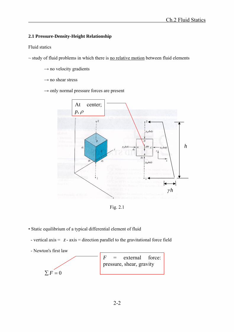
2.1 Pressure-Density-Height Relationship
Fluid statics
~ study of fluid problems in which there is no relative motion between fluid elements
→ no velocity gradients
→ no shear stress
→ only normal pressure forces are present
Fig. 2.1
• Static equilibrium of a typical differential element of fluid
- vertical axis = z - axis = direction parallel to the gravitational force field
- Newton's first law
0F
F = external force: pressure, shear, gravity
At center; p,
h
h
Ch.2 Fluid Statics
2-3
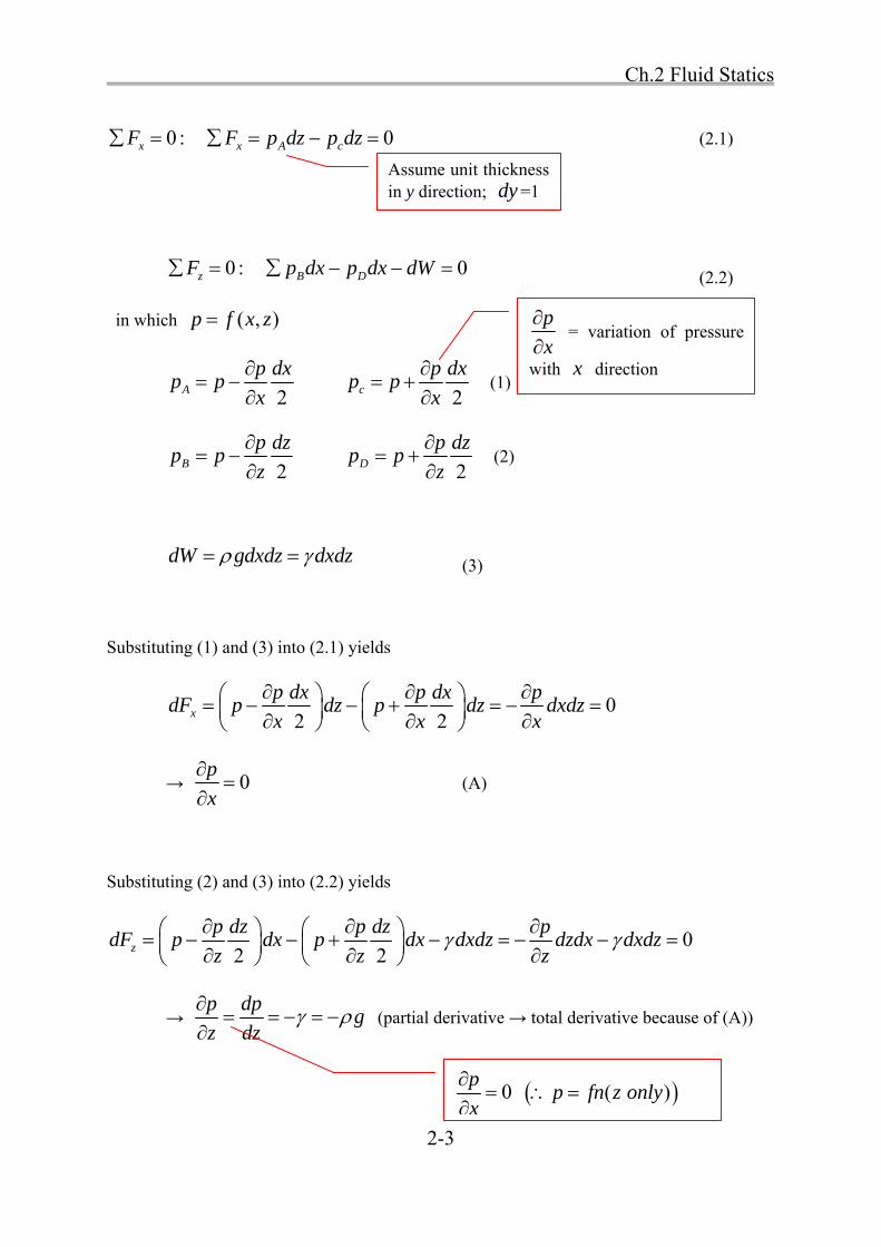
0 :xF 0x A cF p dz p dz (2.1)
0 :zF 0B Dp dx p dx dW (2.2)
in which ( , )p f x z
2A
p dxp p
x
2c
p dxp p
x
(1)
2B
p dzp p
z
2D
p dzp p
z
(2)
dW gdxdz dxdz (3)
Substituting (1) and (3) into (2.1) yields
02 2x
p dx p dx pdF p dz p dz dxdz
x x x
→ 0p
x
(A)
Substituting (2) and (3) into (2.2) yields
02 2z
p dz p dz pdF p dx p dx dxdz dzdx dxdz
z z z
→ p dp
gz dz
(partial derivative → total derivative because of (A))
Assume unit thickness in y direction; dy =1
p
x
= variation of pressure
with x direction
0p
x
( )p fn z only
Ch.2 Fluid Statics
2-4
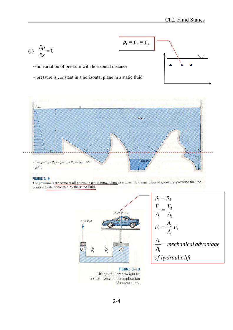
(1) 0p
x
~ no variation of pressure with horizontal distance
~ pressure is constant in a horizontal plane in a static fluid
1 2 3p p p
1 2
1 2
1 2
22 1
1
2
1
p p
F F
A A
AF F
A
Amechanical advantage
A
of hydraulic lift
Ch.2 Fluid Statics
2-5
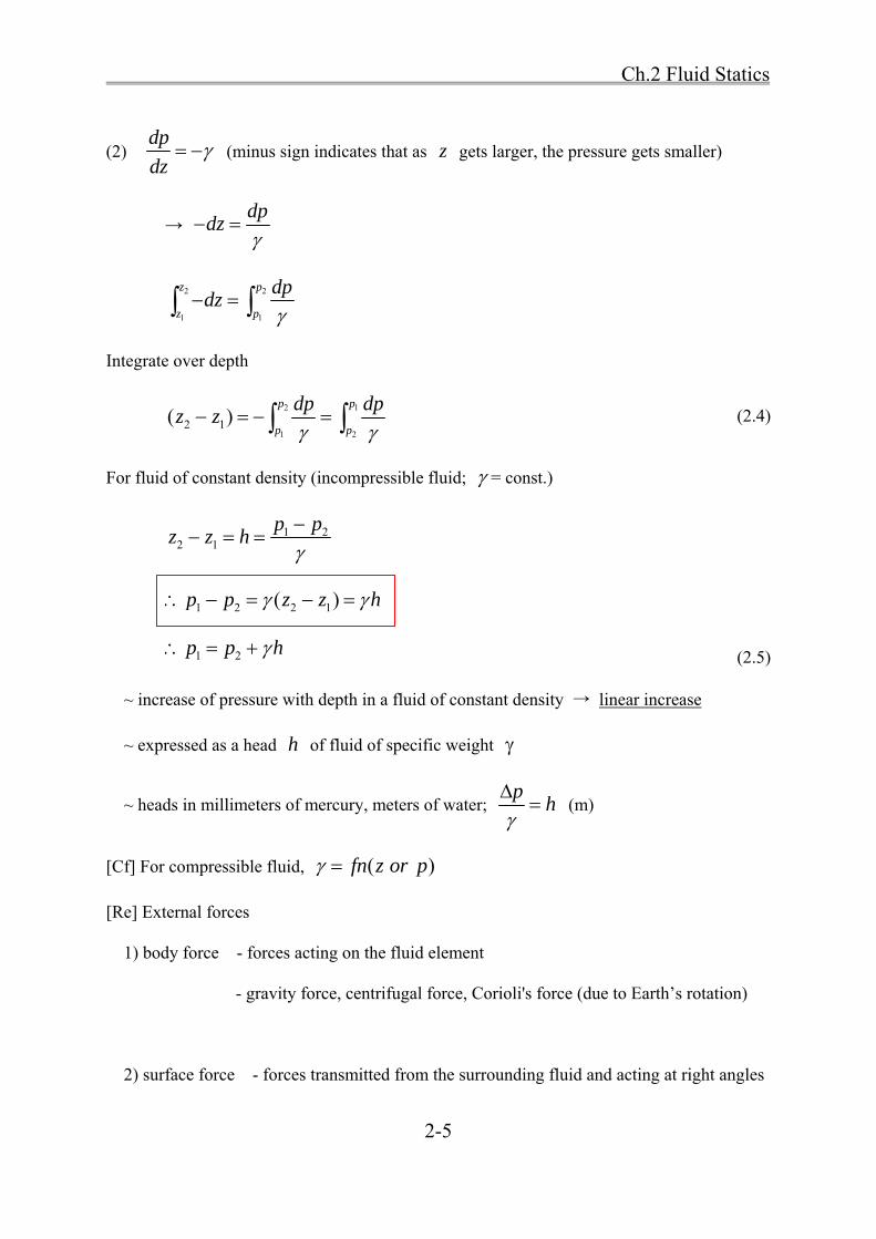
(2) dp
dz (minus sign indicates that as z gets larger, the pressure gets smaller)
→ dp
dz
2 2
1 1
z p
z p
dpdz
Integrate over depth
2 1
1 22 1( )
p p
p p
dp dpz z
(2.4)
For fluid of constant density (incompressible fluid; = const.)
1 22 1
p pz z h
1 2 2 1( )p p z z h
1 2p p h (2.5)
~ increase of pressure with depth in a fluid of constant density → linear increase
~ expressed as a head h of fluid of specific weight
~ heads in millimeters of mercury, meters of water; p
h
(m)
[Cf] For compressible fluid, ( )fn z or p
[Re] External forces
1) body force - forces acting on the fluid element
- gravity force, centrifugal force, Corioli's force (due to Earth’s rotation)
2) surface force - forces transmitted from the surrounding fluid and acting at right angles

Ch.2 Fluid Statics
2-6
against sides of the fluid element
- pressure, shear force
• Manometer or Piezometer
Fig. 2.2
h = height of a column of any fluid
h (m of H2O)2
23
(kN/m )0.102 (kN/m )
9.81 kN/m
pp
• For a static fluid
1 21 2
p pz z
const. (2.6)
w

Ch.2 Fluid Statics
2-7
• For a fluid of variable density (compressible fluid)
~ need to know a relationship between p and
~ oceanography, meteorology
[IP 2.1] The liquid oxygen (LOX) tank of space shuttle booster is filled to a depth of 10 m
with LOX at -196°C. The absolute pressure in the vapor above the liquid surface is 101.3 kPa.
Calculate absolute pressure at the inlet valve.
[Sol]
From App. 2 (Table A2.1)
of LOX at -196°C = 1,206 kg/m3
2 atm LOXp p h
2p = 101.3 kPa+ (1,206 kg/m3) (9.81 m/s2) (10 m)
= 101.3 kPa+ 118,308 kg·m/s2/m2
= 101.3 kPa+ 118,308 kPa
= 219.6 kPa absolute
1 1( )p H z
2 2( )p H z
Bp H
LOX
patm
Ch.2 Fluid Statics
2-8
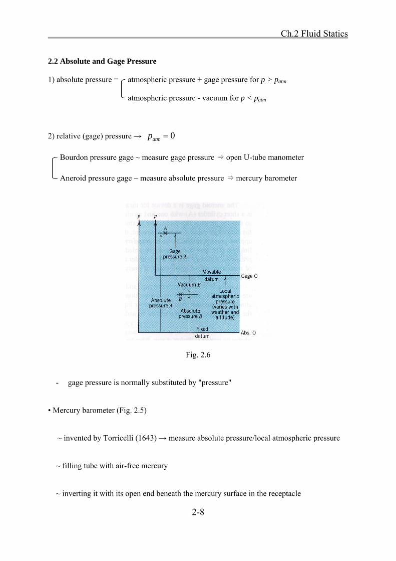
2.2 Absolute and Gage Pressure
1) absolute pressure = atmospheric pressure + gage pressure for p > patm
atmospheric pressure - vacuum for p < patm
2) relative (gage) pressure → 0atmp
Bourdon pressure gage ~ measure gage pressure ⇒ open U-tube manometer
Aneroid pressure gage ~ measure absolute pressure ⇒ mercury barometer
Fig. 2.6
- gage pressure is normally substituted by "pressure"
• Mercury barometer (Fig. 2.5)
~ invented by Torricelli (1643) → measure absolute pressure/local atmospheric pressure
~ filling tube with air-free mercury
~ inverting it with its open end beneath the mercury surface in the receptacle
Ch.2 Fluid Statics
2-9
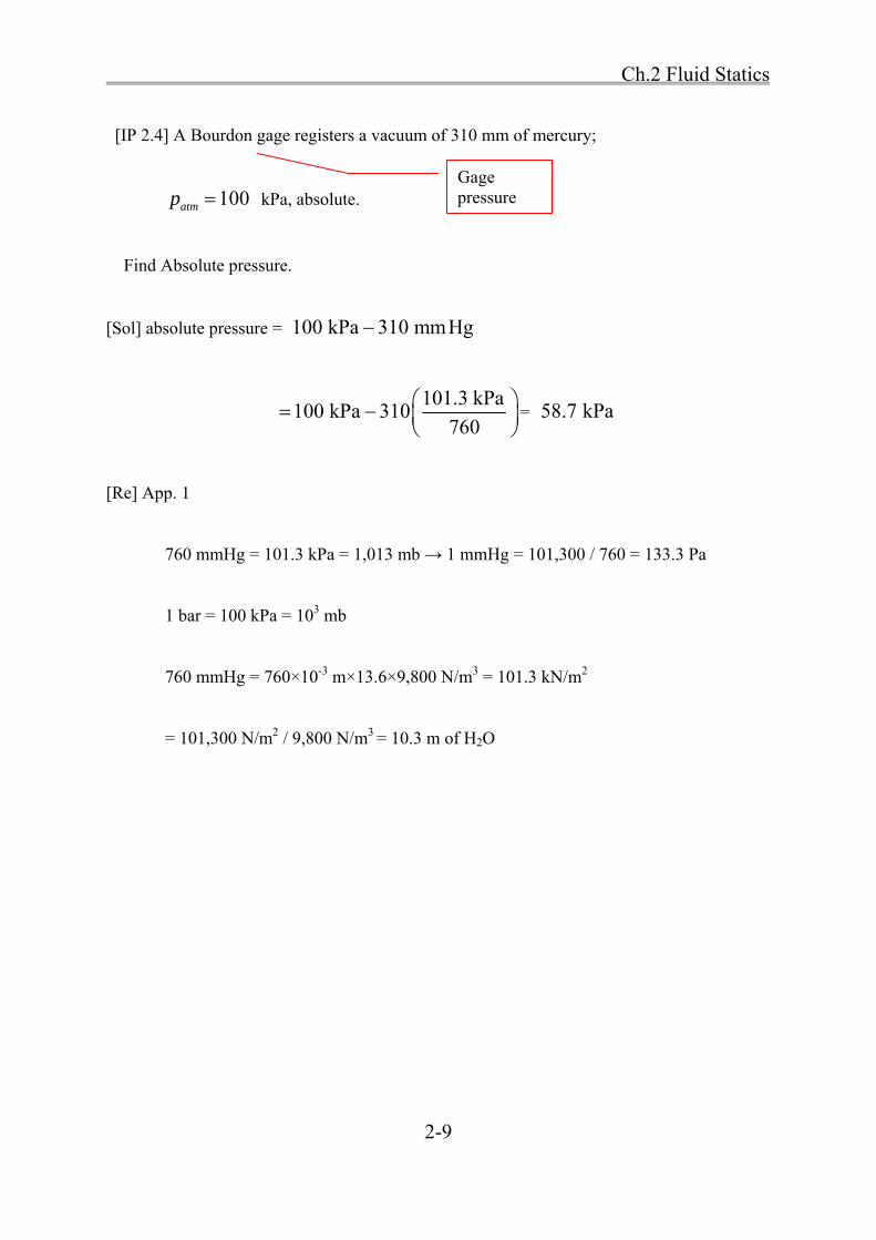
[IP 2.4] A Bourdon gage registers a vacuum of 310 mm of mercury;
100atmp kPa, absolute.
Find Absolute pressure.
[Sol] absolute pressure = 100 kPa 310 mmHg
101.3 kPa
100 kPa 310760
= 58.7 kPa
[Re] App. 1
760 mmHg = 101.3 kPa = 1,013 mb → 1 mmHg = 101,300 / 760 = 133.3 Pa
1 bar = 100 kPa = 103 mb
760 mmHg = 760×10-3 m×13.6×9,800 N/m3 = 101.3 kN/m2
= 101,300 N/m2 / 9,800 N/m3 = 10.3 m of H2O
Gage pressure
Ch.2 Fluid Statics
2-10
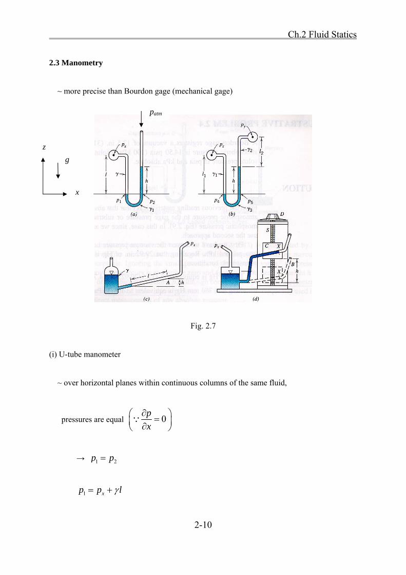
2.3 Manometry
~ more precise than Bourdon gage (mechanical gage)
Fig. 2.7
(i) U-tube manometer
~ over horizontal planes within continuous columns of the same fluid,
pressures are equal 0p
x
→ 1 2p p
1 xp p l
z
x
g
patm

Ch.2 Fluid Statics
2-11
2 10p h
1 2 1; 0xp p p l h
1xp h l
(ii) Differential manometer
~ measure difference between two unknown pressures
4 5p p
4 1 1xp p l 5 2 2 3yp p l h
1 1 2 2 3x yp l p l h
2 2 3 1 1x yp p l l h l
If 1 2 w and x and y are horizontal
3 2 1( )x y wp p h l l
3 3( ) ( )w wh h h
head: 3 1x y
w w
p ph
Patm → 0
-h
Ch.2 Fluid Statics
2-12
(iii) Inclined gages
~ measure the comparatively small pressure in low-velocity gas flows
sinxp h l
reading of l > reading of h → accurate
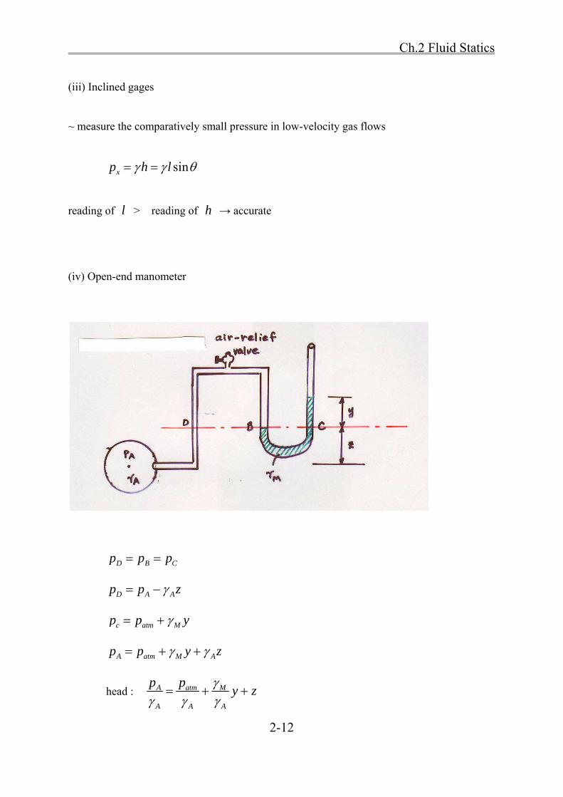
(iv) Open-end manometer
D B Cp p p
D A Ap p z
c atm Mp p y
A atm M Ap p y z
head : A atm M
A A A
p py z

Ch.2 Fluid Statics
2-13
(v) Measure vacuum
1 2p p
1 A A Mp p z y
2 atmp p
A A M atmp z y p
A atm A Mp p z y
(vi) Differential manometer
1 2p p
1 A Ap p z
2 B B Mp p z y
A A B B Mp z p z y
A atmp p vacuum

Ch.2 Fluid Statics
2-14
( )A B A B Mp p z z y
( )M My y y
1A B Mp py
If w → ( . . 1)A BM
w
p ps g y

Ch.2 Fluid Statics
2-15
Differential manometer
Ch.2 Fluid Statics
2-16
Ch.2 Fluid Statics
2-17
For measuring large pressure difference,
→ use heavy measuring liquid, such as mercury . . 13.55s g → makes y small
For a small pressure difference,
→ use a light fluid such as oil, or even air . . 1s g
• Practical considerations for manometry
Temperature effects on densities of manometer liquids should be appreciated.①
Errors due ② to capillarity may frequently be canceled by selecting manometer tubes of
uniform sizes.
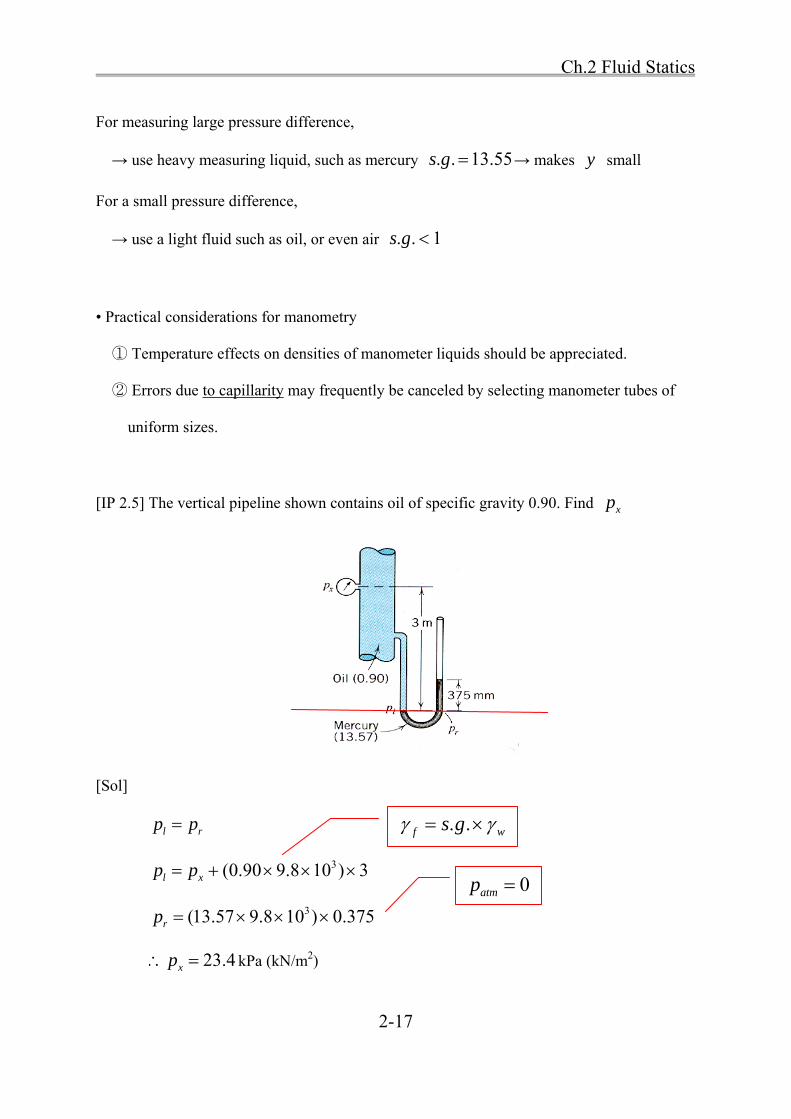
[IP 2.5] The vertical pipeline shown contains oil of specific gravity 0.90. Find xp
[Sol]
l rp p
3(0.90 9.8 10 ) 3l xp p
3(13.57 9.8 10 ) 0.375rp
23.4xp kPa (kN/m2)
. .f ws g
0atmp

Ch.2 Fluid Statics
2-18
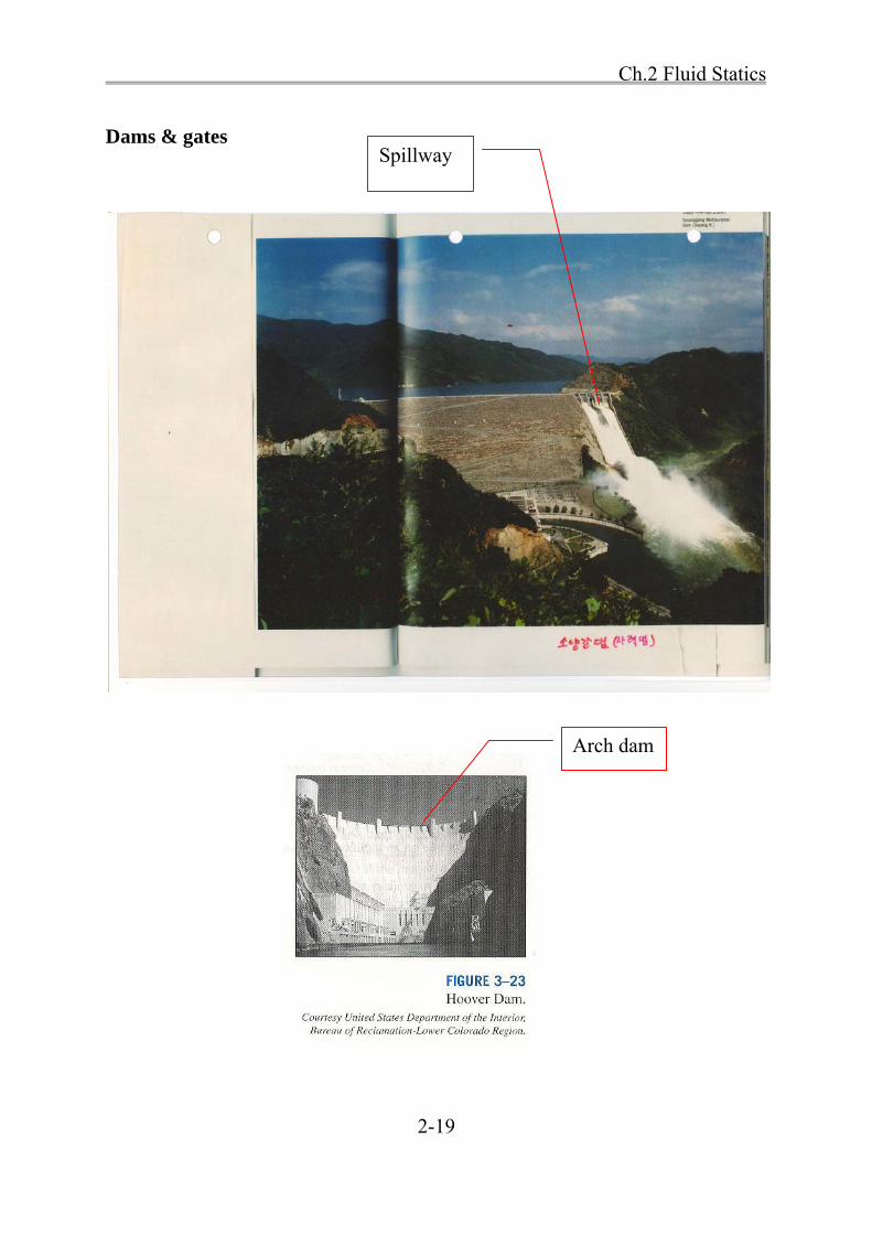
2.4 Forces on Submerged Plane Surfaces
• Calculation of magnitude, direction, and location of the total forces on surfaces submerged
in a liquid is essential.
→ design of dams, bulkheads, gates, tanks, ships
• Pressure variation for non-horizontal planes
p
z
p h
→ The pressure varies linearly with depth.
Fig. 2.8
Ch.2 Fluid Statics
2-19
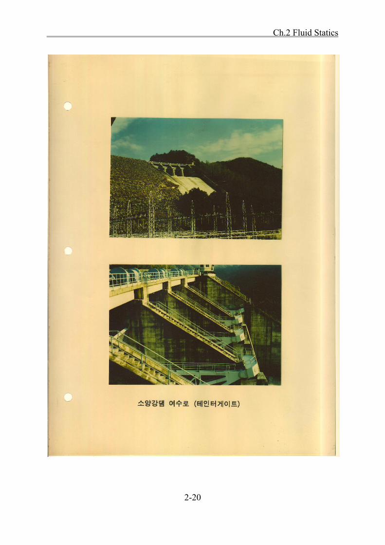
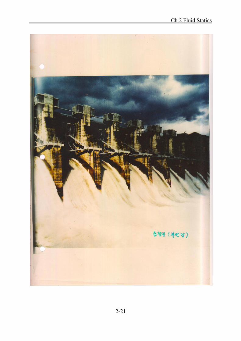
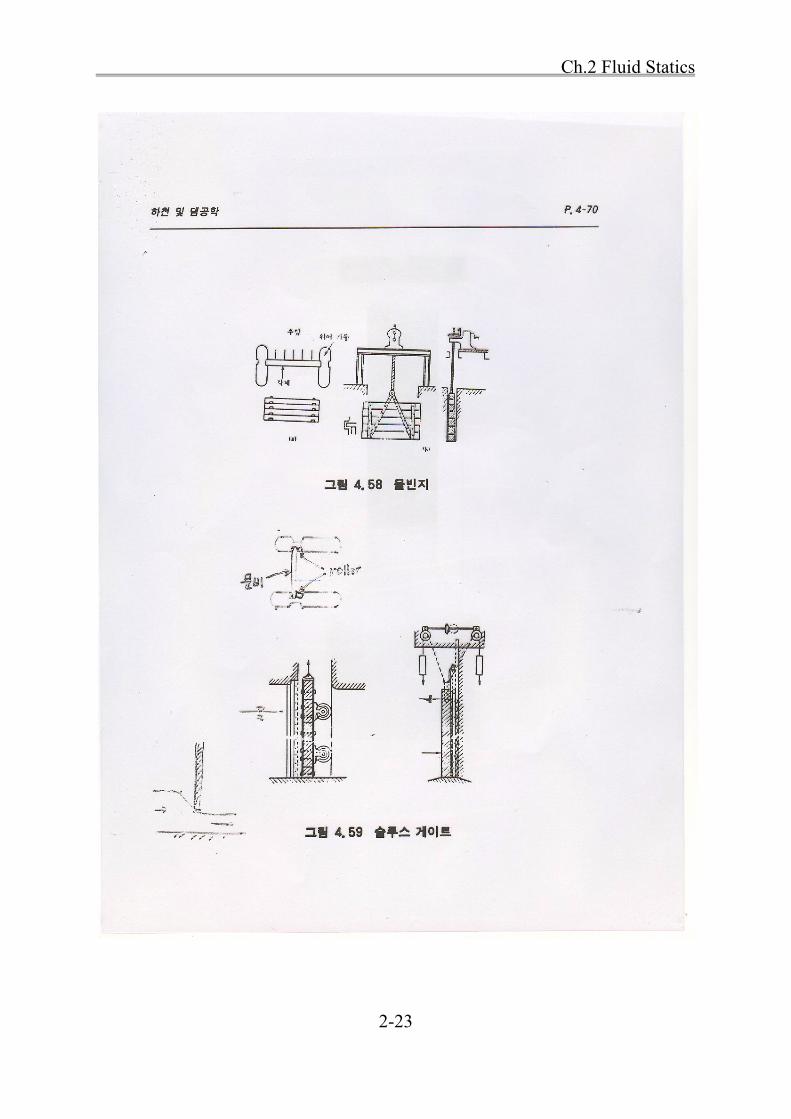
Dams & gates
Spillway
Arch dam
Ch.2 Fluid Statics
2-20
Ch.2 Fluid Statics
2-21
Ch.2 Fluid Statics
2-22
Ch.2 Fluid Statics
2-23
Ch.2 Fluid Statics
2-24
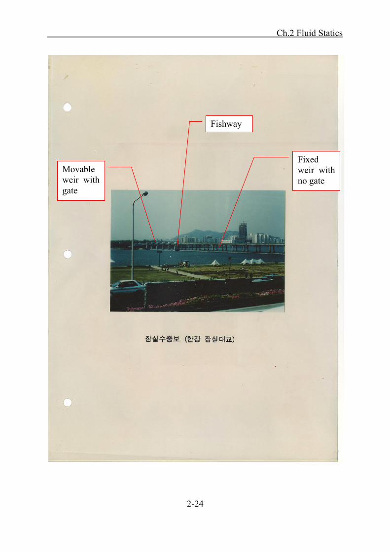
Movable weir with gate
Fixed weir with no gate
Fishway

Ch.2 Fluid Statics
2-25
• Pressure on the inclined plane
Fig. 2.9
• Centroid of area A ~ at a depth ch
~ at a distance cl from the line of intersection 0-0
(i)Magnitude of total force
First, consider differential force dF
dF pdA hdA
sinh l
→ sindF l dA (2.10)
Then, integrate dF over area A
sinA A
F dF ldA (2.11)
I0-0
Ic
Center of resultant force

Ch.2 Fluid Statics
2-26
in which AldA = 1st moment of the area A about the line 0-0
cA l
in which cl = perpendicular distance from 0-0 to the centroid of area
sincF Al
Substitute sinc ch l
cF h A (2.12)
(ii) Location of total force
Consider moment of force about the line 0-0
2 sindM dF l l d
2sinA A
M dM l dA
where 2Al dA = second moment of the area A, about the line 0-0 0 0I
0 0sinM I (a)
By the way,
pM F l (total force × moment arm) (b)
pl = unknown
(pressure at centroid) × (area of plane)
sindF l dA
Ch.2 Fluid Statics
2-27
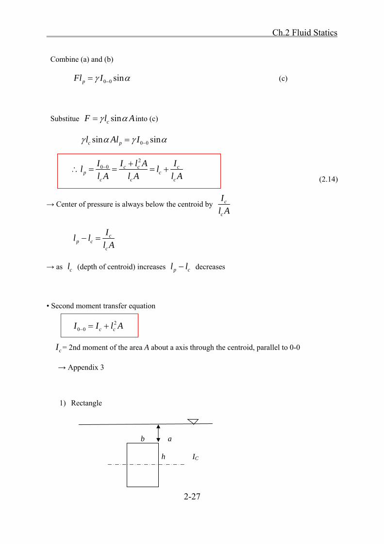
Combine (a) and (b)
0 0 sinpFl I (c)
Substitue sincF l A into (c)
0 0sin sinc pl Al I
2
0 0 c c cp c
c c c
I I l A Il l
l A l A l A
(2.14)
→ Center of pressure is always below the centroid by c
c
I
l A
cp c
c
Il l
l A
→ as cl (depth of centroid) increases p cl l decreases
• Second moment transfer equation
20 0 c cI I l A
cI = 2nd moment of the area A about a axis through the centroid, parallel to 0-0
→ Appendix 3
1) Rectangle
b a
h IC

Ch.2 Fluid Statics
2-28
,A bh ,2c
hy
3
12c
bhI
( )2c c
hh a h y a
( )2c
hF h A a bh
cp c
c
Ih h
h A
If 0a ; 2c
hh
3
2122 2 6 3
2
p
bhh h h
h hh
bh
2) Semicircle
I
Ic
4 4
,128 3c
d rI y
2c cI I y A
2c cI I y A
24 24
128 3 8
d r d
4 410.10976
128 18d r
yc
Ch.2 Fluid Statics
2-29
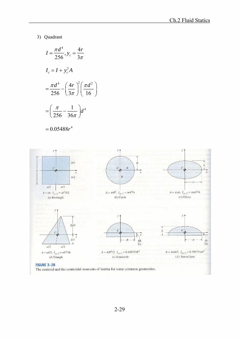
3) Quadrant
4 4
,256 3c
d rI y
2c cI I y A
24 24
256 3 16
d r d
41
256 36d
40.05488r

Ch.2 Fluid Statics
2-30
(iii) Lateral location of the center of pressure for asymmetric submerged area
Fig. 2.10
a. For regular plane
(i) divide whole area into a series of elemental horizontal strips of area dA
(ii) center of pressure for each strip would be at the midpoint of the strip (the strip is a
rectangle in the limit)
(iii) apply moment theorem about a vertical axis 0-0
sincdF h dA l dA (a)
sinc cdM x dF x l dA
Integrate (a)
sincAM dM x l dA (b)
By the way, pM x F (c)
Equate (b) and (c)
axis 0-0

Ch.2 Fluid Statics
2-31
sinp cx F x l dA
1sinp cx x ldA
F (2.15)
b. For irregular forms
~ divide into simple areas
~ use methods of statics
[Re] Moment theorem
→ The moment of the resultant force is equal to the sum of the moments of the individual
forces.
Ch.2 Fluid Statics
2-32
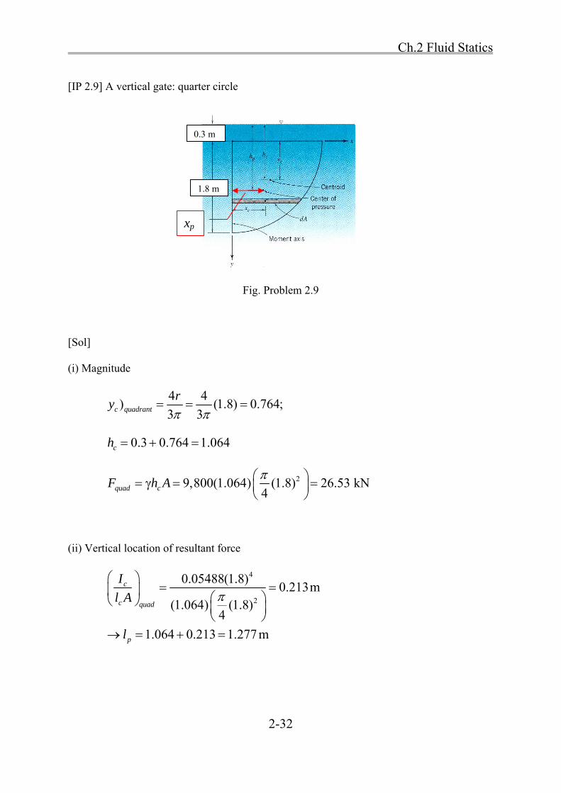
[IP 2.9] A vertical gate: quarter circle
Fig. Problem 2.9
[Sol]
(i) Magnitude
4 4
) (1.8) 0.764;3 3c quadrant
ry
0.3 0.764 1.064ch
29,800(1.064) (1.8) 26.53 kN4quad cF h A
(ii) Vertical location of resultant force
4
2
0.05488(1.8)0.213m
(1.064) (1.8)4
1.064 0.213 1.277 m
c
c quad
p
I
l A
l
1.8 m
0.3 m
xp
Ch.2 Fluid Statics
2-33
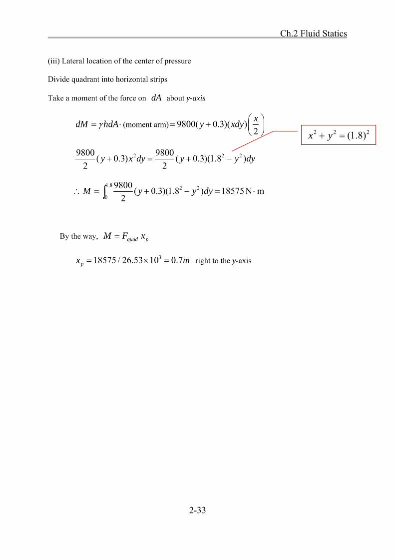
(iii) Lateral location of the center of pressure
Divide quadrant into horizontal strips
Take a moment of the force on dA about y-axis
dM hdA (moment arm) 9800( 0.3)( )2
xy xdy
2 2 29800 9800( 0.3) ( 0.3)(1.8 )
2 2y x dy y y dy
1.8 2 2
0
9800( 0.3)(1.8 ) 18575N m
2M y y dy
By the way, quad pM F x
318575 / 26.53 10 0.7px m right to the y-axis
2 2 2(1.8)x y

Ch.2 Fluid Statics
2-34
2.5 Forces on Submerged Curved Surfaces
• Resultant pressure forces on curved surfaces are more difficult to deal with because the
incremental pressure forces vary continually in direction.
→ Direct integration
Method of basic mechanics
H
D E

Ch.2 Fluid Statics
2-35
1) Direct integration
- Represent the curved shape functionally and integrate to find horizontal and vertical
components of the resulting force
i) Horizontal component
H HF dF hbdz
where b = the width of the surface; dz = the vertical projection of the surface element dL
location of FH: take moments of dF about convenient point, e.g., point C
p H Hz F z dF z hbdz
where zp = the vertical distance from the moment center to FH
ii) Vertical component
V VF dF hbdx
where dx = the horizontal projection of the surface element dL
location of FV: take moments of dF about convenient point, e.g., point C
p V Vx F x dF x hbdx
where xp = the horizontal distance from the moment center to FV
2) Method of basic mechanics
- Use the basic mechanics concept of a free body and the equilibrium of a fluid mass
- Choose a convenient volume of fluid in a way that one of the fluid element boundaries
coincide with the curved surface under consideration
Ch.2 Fluid Statics
2-36
- Isolate the fluid mass and show all the forces acting on the mass to keep it in
equilibrium
• Static equilibrium of free body ABC
' 0x BC HF F F 'H BC c BCF F h A
' 0z V ABC ACF F W F 'V AC ABCF F W
AC c AC AC ACDEF h A HA W
ABCW weight of free body ABC
'VF weight of ABDE
• Location
From the inability of the free body of fluid to support shear stress,
→ 'HF must be colinear with BCF
→ 'VF must be colinear with the resultant of ABCW and ACF .
Ch.2 Fluid Statics
2-37
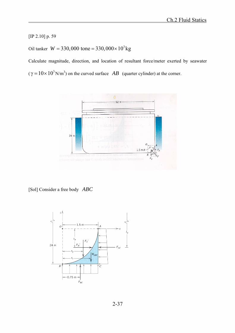
[IP 2.10] p. 59
Oil tanker 3330,000 tone 330,000 10 kgW
Calculate magnitude, direction, and location of resultant force/meter exerted by seawater
( 310 10 N/m3) on the curved surface AB (quarter cylinder) at the corner.
[Sol] Consider a free body ABC
Ch.2 Fluid Statics
2-38
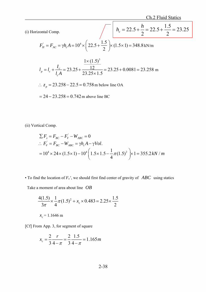
(i) Horizontal Comp.
' 4 1.510 22.5 (1.5 1) 348.8
2H AC cF F h A
kN/m
31 (1.5)
1223.25 23.25 0.0081 23.25823.25 1.5
cp c
c
Il l
l A
m
23.258 22.5 0.758pz m below line OA
24 23.258 0.742 m above line BC
(ii) Vertical Comp.
' 0z BC V ABCF F F W ' .V BC ABC cF F W h A Vol
4 4 2110 24 (1.5 1) 10 1.5 1.5 (1.5) 1 355.2 /
4kN m
• To find the location of Fv’, we should first find center of gravity of ABC using statics
Take a moment of area about line OB
24(1.5) 1 1.5(1.5) 0.483 2.25
3 4 2cx
cx = 1.1646 m
[Cf] From App. 3, for segment of square
2 2 1.51.165
3 4 3 4c
rx m
1.522.5 22.5 23.25
2 2c
hh

Ch.2 Fluid Statics
2-39
Now, find location of force 'VF
Take a moment of force about point O
' 0.75 1.1646V p BC ABCF x F W
355.2 360 0.75 4.83 1.1646px
0.744px m right of OB
[Summary]
i) Magnitude of Resultant force F
2 2(348.8) (355.2) 497.8F kN/m
ii) Direction
1 1 355.2tan tan 45.5
348.8V
H
F
F
iii) Location
Force acting through a point 0.742 m above line BC and 0.744 m right of B
11
0.744tan 44.47
0.758
12
348.8tan 44.47
355.2
1 2 → F act through point O.
1
2
HF
VF

Ch.2 Fluid Statics
2-40
• Pressure acting on the cylindrical or spherical surface
- The pressure forces are all normal to the surface.
- For a circular arc, all the lines of action would pass through the center of the arc.
→ Hence, the resultant would also pass through the center.
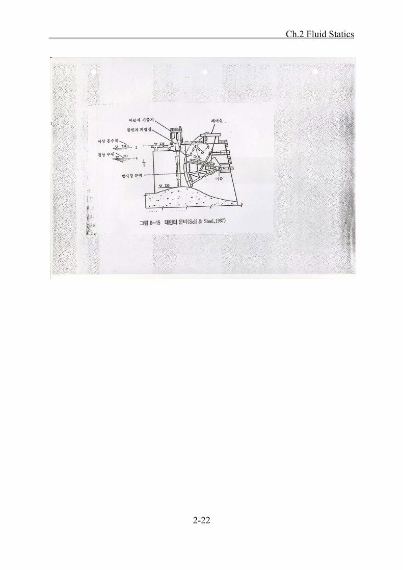
• Tainter gate (Radial gate) for dam spillway
All hydrostatic pressures are radial, passing through the trunnion bearing.
→ only pin friction should be overcome to open the gate
pin friction (radial gate) < roller friction (lift gate)
Trunnion pin

Ch.2 Fluid Statics
2-41
2.6 Buoyancy and Floatation
• Archimedes' principle
I. A body immersed in a fluid is buoyed up by a force equal to the weight of fluid displaced.
II. A floating body displaces its own weight of the liquid in which it floats.
→ Calculation of draft of surface vessels, lift of airships and balloons
(i) Immersed body
Fig. 2.12
Isolate a free body of fluid with vertical sides tangent to the body
→ 1F = vertical force exerted by the lower surface (ADC) on the surrounding fluid
2F = vertical force exerted by the upper surface (ABC) on the surrounding fluid
1 2 BF F F
BF = buoyancy of fluid; act vertically upward.
For upper portion of free body
'2 2 2 0zF F W P A (a)

Ch.2 Fluid Statics
2-42
For lower portion
'1 1 1 0zF F W P A (b)
Combine (a) and (b)
' '1 2 1 2 1 2( ) ( )BF F F P P A W W
1 2( )P P A hA weight of free body
1 2W W weight of dashed portion of fluid
1 2 1 2( ) ( )P P A W W weight of a volume of fluid equal to that of the body
ABCD
B fluidF (volume of submerged object) (2.16)
(ii) Floating body
For floating object
B fF (volume displaced, ABCD ) B fF ABCD
ABCDE s ABCDEW V sW ABCDE
where s = specific weight of body
h
E

Ch.2 Fluid Statics
2-43
From static equilibrium: B ABCDEF W
f ABCD s ABCDEV V
sA B C D A B C D E
f
V V
[Ex] Iceberg in the sea
Ice s.g.= 0.9
Sea water s.g.= 1.03
0.9(9800)
0.971.03(9800)sub total totalV V V
• Stability of submerged or floating bodies
1G M →stable, righting moment
2G M →unstable, overturning moment
1 2,G G =center of gravity
M = metacenter
Ch.2 Fluid Statics
2-44
2.7 Fluid Masses Subjected to Acceleration
• Fluid masses can be subjected to various types of acceleration without the occurrence of
relative motion between fluid particles or between fluid particles and boundaries.
→ laws of fluid statics modified to allow for the effects of acceleration
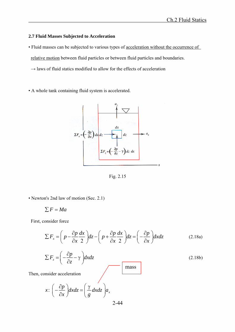
• A whole tank containing fluid system is accelerated.
Fig. 2.15
• Newton's 2nd law of motion (Sec. 2.1)
F Ma
First, consider force
2 2x
p dx p dx pF p dz p dz dxdz
x x x
(2.18a)
z
pF dxdz
z
(2.18b)
Then, consider acceleration
: x
px dxdz dxdz a
x g
mass

Ch.2 Fluid Statics
2-45
: z
pz dxdz dxdz a
z g
where mass = . 1vol dxdzg
x
pa
x g
(2.19)
( )z
pg a
z g
(2.20)
→ pressure variation through an accelerated mass of fluid
[Cf] For fluid at rest,
0p
x
p
z

Ch.2 Fluid Statics
2-46
• Chain rule for the total differential for dp (App. 5)
p pdp dx dz
x z
(a)
Combine (2.19) , (2.20), and (a)
( )x zdp a dx g a dzg g
(2.21)
• Line of constant pressure 0dp
( ) 0x za dx g a dzg g
x
x
dz a
dx g a
(2.22)
→ slope of a line of constant pressure

Ch.2 Fluid Statics
2-47
1) No horizontal acceleration: 0xa
0p
x
zdp g a
dz g
• For free falling fluid, za g
0dp
dz
2) Constant linear acceleration
Divide (2.21) by dh
x zdp a dx g a dz
dh g dh g dh
(a)
Use similar triangles
'
xdx a
dh g
(b.1)
'
zdz a g
dh g
(b.2)
1/2' 2 2( )x zg a a g
Substitute (b) into (a)

Ch.2 Fluid Statics
2-48
'dp g
dh g
→ pressure variation along h is linear.
[IP 2.13] p. 70
An open tank of water is accelerated vertically upward at 4.5 m/s2. Calculate the pressure at a
depth of 1.5 m.
[Sol]
3 39.81 4.5( 9,800 N/m ) 14,300 N/m
9.81zdp g a
dz g
14,300dp dz
integrate
1.5
0 014,300
pdp dz
1.5 2014,300[ ] 14,300( 1.5 0) 21,450 N/m 21.45 kPap z
[Cf] For 0za
9800(1.5) 14.7 kPap h

Ch.2 Fluid Statics
2-49
Homework Assignment # 2
Due: 1 week from today
Prob. 2.4
Prob. 2.6
Prob. 2.11
Prob. 2.26
Prob. 2.31
Prob. 2.39
Prob. 2.52
Prob. 2.59
Prob. 2.63
Prob. 2.76
Prob. 2.91
Prob. 2.98
Prob. 2.129