
Chapter 2 Design and Construction - Ministerul...
50
2-1 Design and Construction Chapter 2 Introduction It is important for the aspiring rigger to understand basic design parameters and construction techniques of modern parachute systems. The master rigger must have a thorough understanding of these areas to perform any desired or necessary alterations. An understanding of how the systems or components were originally designed, and why they were constructed as they were, is essential. Any proposed alteration may degrade the function and/or structural integrity of the assembly or component thereby causing it to fail.
Transcript of Chapter 2 Design and Construction - Ministerul...

2-1
Design and ConstructionChapter 2
IntroductionIt is important for the aspiring rigger to understand basic design parameters and construction techniques of modern parachute systems. The master rigger must have a thorough understanding of these areas to perform any desired or necessary alterations. An understanding of how the systems or components were originally designed, and why they were constructed as they were, is essential. Any proposed alteration may degrade the function and/or structural integrity of the assembly or component thereby causing it to fail.
2-2
Canopy
Suspension lines
Slider
Steering lines
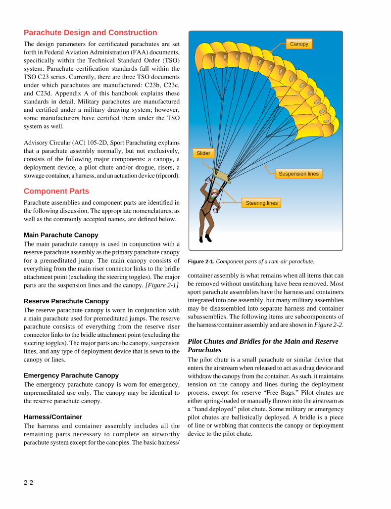
Figure 2-1. Component parts of a ram-air parachute.
Parachute Design and ConstructionThe design parameters for certificated parachutes are set forth in Federal Aviation Administration (FAA) documents, specifically within the Technical Standard Order (TSO) system. Parachute certification standards fall within the TSO C23 series. Currently, there are three TSO documents under which parachutes are manufactured: C23b, C23c, and C23d. Appendix A of this handbook explains these standards in detail. Military parachutes are manufactured and certified under a military drawing system; however, some manufacturers have certified them under the TSO system as well.
Advisory Circular (AC) 105-2D, Sport Parachuting explains that a parachute assembly normally, but not exclusively, consists of the following major components: a canopy, a deployment device, a pilot chute and/or drogue, risers, a stowage container, a harness, and an actuation device (ripcord).
Component Parts Parachute assemblies and component parts are identified in the following discussion. The appropriate nomenclatures, as well as the commonly accepted names, are defined below.
Main Parachute Canopy The main parachute canopy is used in conjunction with a reserve parachute assembly as the primary parachute canopy for a premeditated jump. The main canopy consists of everything from the main riser connector links to the bridle attachment point (excluding the steering toggles). The major parts are the suspension lines and the canopy. [Figure 2-1]
Reserve Parachute CanopyThe reserve parachute canopy is worn in conjunction with a main parachute used for premeditated jumps. The reserve parachute consists of everything from the reserve riser connector links to the bridle attachment point (excluding the steering toggles). The major parts are the canopy, suspension lines, and any type of deployment device that is sewn to the canopy or lines.
Emergency Parachute CanopyThe emergency parachute canopy is worn for emergency, unpremeditated use only. The canopy may be identical to the reserve parachute canopy.
Harness/ContainerThe harness and container assembly includes all the remaining parts necessary to complete an airworthy parachute system except for the canopies. The basic harness/
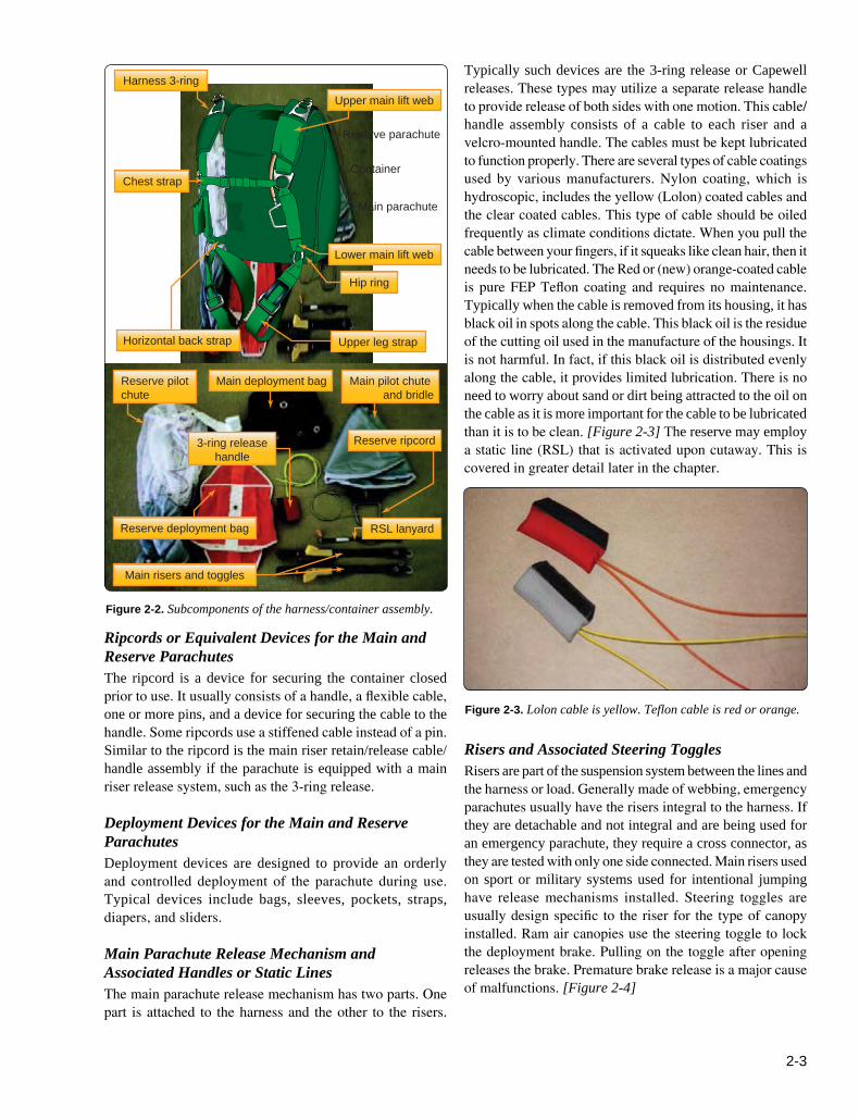
container assembly is what remains when all items that can be removed without unstitching have been removed. Most sport parachute assemblies have the harness and containers integrated into one assembly, but many military assemblies may be disassembled into separate harness and container subassemblies. The following items are subcomponents of the harness/container assembly and are shown in Figure 2-2.
Pilot Chutes and Bridles for the Main and Reserve Parachutes The pilot chute is a small parachute or similar device that enters the airstream when released to act as a drag device and withdraw the canopy from the container. As such, it maintains tension on the canopy and lines during the deployment process, except for reserve “Free Bags.” Pilot chutes are either spring-loaded or manually thrown into the airstream as a “hand deployed” pilot chute. Some military or emergency pilot chutes are ballistically deployed. A bridle is a piece of line or webbing that connects the canopy or deployment device to the pilot chute.
2-3
Chest strap
Horizontal back strap Upper leg strap
Hip ring
Lower main lift web
Upper main lift webHarness 3-ring
Reserve parachute
Container
Main parachute
Reserve deployment bag
Main risers and toggles
Reserve pilot chute
Main deployment bag Main pilot chute and bridle
RSL lanyard
3-ring releasehandle
Reserve ripcord
Figure 2-2. Subcomponents of the harness/container assembly.
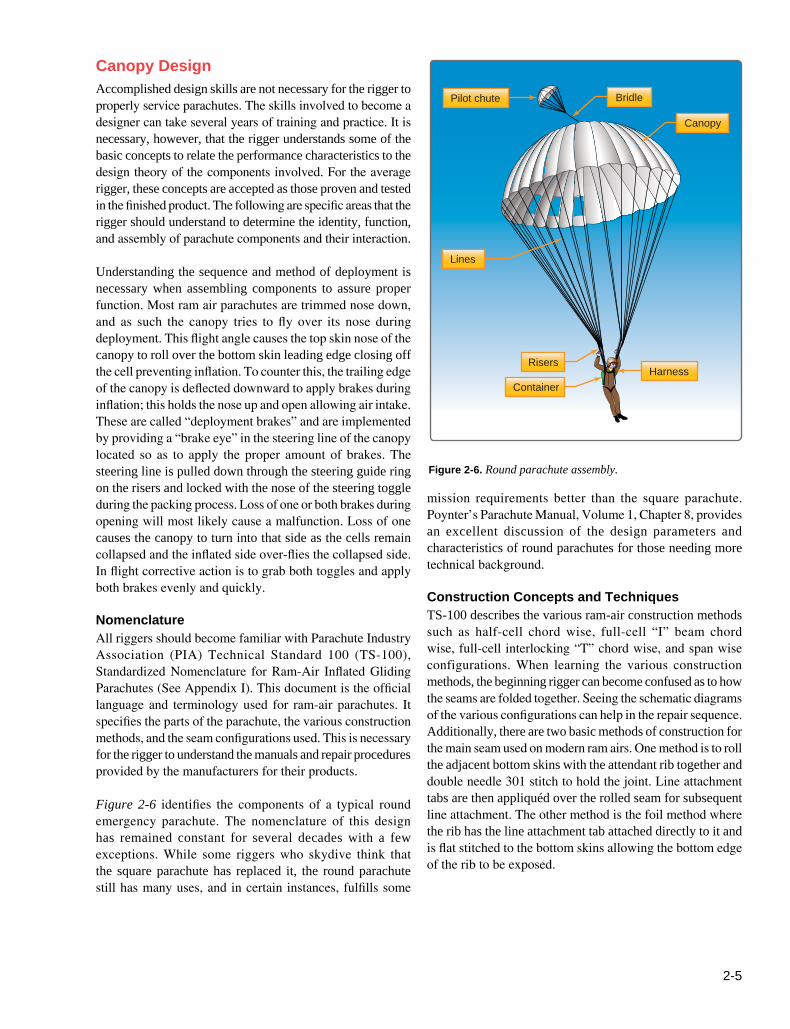
Figure 2-3. Lolon cable is yellow. Teflon cable is red or orange.
Ripcords or Equivalent Devices for the Main and Reserve Parachutes The ripcord is a device for securing the container closed prior to use. It usually consists of a handle, a flexible cable, one or more pins, and a device for securing the cable to the handle. Some ripcords use a stiffened cable instead of a pin. Similar to the ripcord is the main riser retain/release cable/handle assembly if the parachute is equipped with a main riser release system, such as the 3-ring release.
Deployment Devices for the Main and Reserve ParachutesDeployment devices are designed to provide an orderly and controlled deployment of the parachute during use. Typical devices include bags, sleeves, pockets, straps, diapers, and sliders.
Main Parachute Release Mechanism and Associated Handles or Static Lines The main parachute release mechanism has two parts. One part is attached to the harness and the other to the risers.
Typically such devices are the 3-ring release or Capewell releases. These types may utilize a separate release handle to provide release of both sides with one motion. This cable/handle assembly consists of a cable to each riser and a velcro-mounted handle. The cables must be kept lubricated to function properly. There are several types of cable coatings used by various manufacturers. Nylon coating, which is hydroscopic, includes the yellow (Lolon) coated cables and the clear coated cables. This type of cable should be oiled frequently as climate conditions dictate. When you pull the cable between your fingers, if it squeaks like clean hair, then it needs to be lubricated. The Red or (new) orange-coated cable is pure FEP Teflon coating and requires no maintenance. Typically when the cable is removed from its housing, it has black oil in spots along the cable. This black oil is the residue of the cutting oil used in the manufacture of the housings. It is not harmful. In fact, if this black oil is distributed evenly along the cable, it provides limited lubrication. There is no need to worry about sand or dirt being attracted to the oil on the cable as it is more important for the cable to be lubricated than it is to be clean. [Figure 2-3] The reserve may employ a static line (RSL) that is activated upon cutaway. This is covered in greater detail later in the chapter.
Risers and Associated Steering TogglesRisers are part of the suspension system between the lines and the harness or load. Generally made of webbing, emergency parachutes usually have the risers integral to the harness. If they are detachable and not integral and are being used for an emergency parachute, they require a cross connector, as they are tested with only one side connected. Main risers used on sport or military systems used for intentional jumping have release mechanisms installed. Steering toggles are usually design specific to the riser for the type of canopy installed. Ram air canopies use the steering toggle to lock the deployment brake. Pulling on the toggle after opening releases the brake. Premature brake release is a major cause of malfunctions. [Figure 2-4]

2-4
TSO DocumentsTSO number C23b C23c C23d
Performance standardEffective datesPerformance specifications
Placard limitations
Number of drop tests
NAS-8041949-1984Low speed 3000 lb
Standard category 5000 lb
Low speed 3000 lb
Standard category 5000 lb
AS-8015a1984-1994Category A Weight: 300 lb Speed: 150 knotsCategory B Weight: 300 lb Speed: 175 knotsCategory C Weight: 300 lb Speed: 230 knotsCategory A Weight: 198 lb Speed: 130 knotsCategory B Weight: 254 lb Speed: 150 knotsCategory C Weight: 254 lb Speed: 175 knots
AS-8015b1994-PresentVariable-Maximum operating weight x 1.2Maximum operating weight x 1.2
Placard with average peak forcemeasured during the strength drop.
28 68 68
Figure 2-4. Toggle through brake eye and stowed.
Figure 2-5. TSO comparisons.
Aerospace Standard AS-8015. When the TSO was revised again in 1994, the revised document became AS-8015b with the original as AS-8015a. Figure 2-5 is a table showing the pertinent points of each of the TSO certifications. For a more thorough study of the documents, refer to Appendix B.
The TSO system consists of two parts. The first is the performance standards listed above. This ensures that the parachute performs as specified. The second is the production approval, which ensures that the manufacturer is able to produce the parachute as designed and tested. While minor design changes are allowed, any major design change must be submitted to the FAA for approval before implementation. A major change is anything that affects the airworthiness of the system of the parachute.
For the aspiring rigger, the primary purpose of knowing the TSO system is determining the compatibility of components when assembling the parachute system. This is necessary in order to ensure that, besides fitting together properly, the performance standards are compatible. Under Advisory Circular (AC) 105-2, Sport Parachute Jumping, “the assembly or mating of separately approved components may be made by a certificated and appropriately rated parachute rigger or parachute loft in accordance with the manufacturer’s instructions and without further authorization by the manufacturer or the FAA.” Under these guidelines, there are certain parameters that must be met. One of them is to ensure that “the strength of the harness must always be equal to or greater than the maximum force generated by the canopy during the certification tests.” Full knowledge of the TSO documents ensures that the above requirements are met.
Other Harness/Container Assembly Components Other components designed to function as part of the harness/container assembly, such as closing loops, also may be used. Closing loops used with automatic activation devices (AADs) on reserve or emergency parachutes are usually design specific to ensure proper operation of the system.
TSO StandardsThe original TSO C23b for parachutes came into existence in 1949. The specifications were revised in 1984 to C23c and again in 1994 to C23d. The TSO is a simple two-page document that specifies the requirements for certification. This document also references a performance standard that the parachute must meet. C23b parachutes were tested to standards under National Aircraft Standards Specifications NAS-804. When the TSO was revised in 1984, the specification document was drafted under the auspices of the Society of Automotive Engineers (SAE) S-17 committee as
2-5
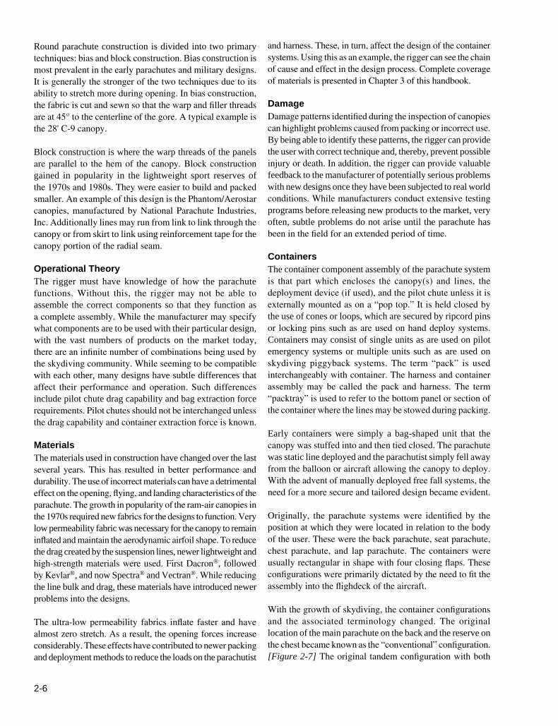
Bridle
Canopy
Pilot chute
HarnessRisers
Container
Lines
Figure 2-6. Round parachute assembly.
mission requirements better than the square parachute. Poynter’s Parachute Manual, Volume 1, Chapter 8, provides an excellent discussion of the design parameters and characteristics of round parachutes for those needing more technical background.
Construction Concepts and Techniques TS-100 describes the various ram-air construction methods such as half-cell chord wise, full-cell “I” beam chord wise, full-cell interlocking “T” chord wise, and span wise configurations. When learning the various construction methods, the beginning rigger can become confused as to how the seams are folded together. Seeing the schematic diagrams of the various configurations can help in the repair sequence. Additionally, there are two basic methods of construction for the main seam used on modern ram airs. One method is to roll the adjacent bottom skins with the attendant rib together and double needle 301 stitch to hold the joint. Line attachment tabs are then appliquéd over the rolled seam for subsequent line attachment. The other method is the foil method where the rib has the line attachment tab attached directly to it and is flat stitched to the bottom skins allowing the bottom edge of the rib to be exposed.
Canopy DesignAccomplished design skills are not necessary for the rigger to properly service parachutes. The skills involved to become a designer can take several years of training and practice. It is necessary, however, that the rigger understands some of the basic concepts to relate the performance characteristics to the design theory of the components involved. For the average rigger, these concepts are accepted as those proven and tested in the finished product. The following are specific areas that the rigger should understand to determine the identity, function, and assembly of parachute components and their interaction.
Understanding the sequence and method of deployment is necessary when assembling components to assure proper function. Most ram air parachutes are trimmed nose down, and as such the canopy tries to fly over its nose during deployment. This flight angle causes the top skin nose of the canopy to roll over the bottom skin leading edge closing off the cell preventing inflation. To counter this, the trailing edge of the canopy is deflected downward to apply brakes during inflation; this holds the nose up and open allowing air intake. These are called “deployment brakes” and are implemented by providing a “brake eye” in the steering line of the canopy located so as to apply the proper amount of brakes. The steering line is pulled down through the steering guide ring on the risers and locked with the nose of the steering toggle during the packing process. Loss of one or both brakes during opening will most likely cause a malfunction. Loss of one causes the canopy to turn into that side as the cells remain collapsed and the inflated side over-flies the collapsed side. In flight corrective action is to grab both toggles and apply both brakes evenly and quickly.
NomenclatureAll riggers should become familiar with Parachute Industry Association (PIA) Technical Standard 100 (TS-100), Standardized Nomenclature for Ram-Air Inflated Gliding Parachutes (See Appendix I). This document is the official language and terminology used for ram-air parachutes. It specifies the parts of the parachute, the various construction methods, and the seam configurations used. This is necessary for the rigger to understand the manuals and repair procedures provided by the manufacturers for their products.
Figure 2-6 identifies the components of a typical round emergency parachute. The nomenclature of this design has remained constant for several decades with a few exceptions. While some riggers who skydive think that the square parachute has replaced it, the round parachute still has many uses, and in certain instances, fulfills some
2-6
Round parachute construction is divided into two primary techniques: bias and block construction. Bias construction is most prevalent in the early parachutes and military designs. It is generally the stronger of the two techniques due to its ability to stretch more during opening. In bias construction, the fabric is cut and sewn so that the warp and filler threads are at 45° to the centerline of the gore. A typical example is the 28' C-9 canopy.
Block construction is where the warp threads of the panels are parallel to the hem of the canopy. Block construction gained in popularity in the lightweight sport reserves of the 1970s and 1980s. They were easier to build and packed smaller. An example of this design is the Phantom/Aerostar canopies, manufactured by National Parachute Industries, Inc. Additionally lines may run from link to link through the canopy or from skirt to link using reinforcement tape for the canopy portion of the radial seam.
Operational TheoryThe rigger must have knowledge of how the parachute functions. Without this, the rigger may not be able to assemble the correct components so that they function as a complete assembly. While the manufacturer may specify what components are to be used with their particular design, with the vast numbers of products on the market today, there are an infinite number of combinations being used by the skydiving community. While seeming to be compatible with each other, many designs have subtle differences that affect their performance and operation. Such differences include pilot chute drag capability and bag extraction force requirements. Pilot chutes should not be interchanged unless the drag capability and container extraction force is known.
MaterialsThe materials used in construction have changed over the last several years. This has resulted in better performance and durability. The use of incorrect materials can have a detrimental effect on the opening, flying, and landing characteristics of the parachute. The growth in popularity of the ram-air canopies in the 1970s required new fabrics for the designs to function. Very low permeability fabric was necessary for the canopy to remain inflated and maintain the aerodynamic airfoil shape. To reduce the drag created by the suspension lines, newer lightweight and high-strength materials were used. First Dacron®, followed by Kevlar®, and now Spectra® and Vectran®. While reducing the line bulk and drag, these materials have introduced newer problems into the designs.
The ultra-low permeability fabrics inflate faster and have almost zero stretch. As a result, the opening forces increase considerably. These effects have contributed to newer packing and deployment methods to reduce the loads on the parachutist
and harness. These, in turn, affect the design of the container systems. Using this as an example, the rigger can see the chain of cause and effect in the design process. Complete coverage of materials is presented in Chapter 3 of this handbook.
DamageDamage patterns identified during the inspection of canopies can highlight problems caused from packing or incorrect use. By being able to identify these patterns, the rigger can provide the user with correct technique and, thereby, prevent possible injury or death. In addition, the rigger can provide valuable feedback to the manufacturer of potentially serious problems with new designs once they have been subjected to real world conditions. While manufacturers conduct extensive testing programs before releasing new products to the market, very often, subtle problems do not arise until the parachute has been in the field for an extended period of time.
ContainersThe container component assembly of the parachute system is that part which encloses the canopy(s) and lines, the deployment device (if used), and the pilot chute unless it is externally mounted as on a “pop top.” It is held closed by the use of cones or loops, which are secured by ripcord pins or locking pins such as are used on hand deploy systems. Containers may consist of single units as are used on pilot emergency systems or multiple units such as are used on skydiving piggyback systems. The term “pack” is used interchangeably with container. The harness and container assembly may be called the pack and harness. The term “packtray” is used to refer to the bottom panel or section of the container where the lines may be stowed during packing.
Early containers were simply a bag-shaped unit that the canopy was stuffed into and then tied closed. The parachute was static line deployed and the parachutist simply fell away from the balloon or aircraft allowing the canopy to deploy. With the advent of manually deployed free fall systems, the need for a more secure and tailored design became evident.
Originally, the parachute systems were identified by the position at which they were located in relation to the body of the user. These were the back parachute, seat parachute, chest parachute, and lap parachute. The containers were usually rectangular in shape with four closing flaps. These configurations were primarily dictated by the need to fit the assembly into the flighdeck of the aircraft.
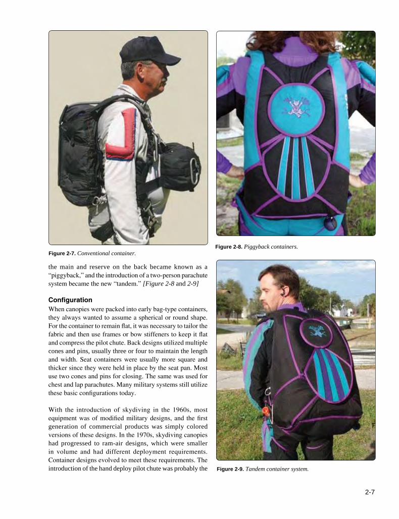
With the growth of skydiving, the container configurations and the associated terminology changed. The original location of the main parachute on the back and the reserve on the chest became known as the “conventional” configuration. [Figure 2-7] The original tandem configuration with both
2-7
Figure 2-8. Piggyback containers.Figure 2-7. Conventional container.
Figure 2-9. Tandem container system.
the main and reserve on the back became known as a “piggyback,” and the introduction of a two-person parachute system became the new “tandem.” [Figure 2-8 and 2-9]
ConfigurationWhen canopies were packed into early bag-type containers, they always wanted to assume a spherical or round shape. For the container to remain flat, it was necessary to tailor the fabric and then use frames or bow stiffeners to keep it flat and compress the pilot chute. Back designs utilized multiple cones and pins, usually three or four to maintain the length and width. Seat containers were usually more square and thicker since they were held in place by the seat pan. Most use two cones and pins for closing. The same was used for chest and lap parachutes. Many military systems still utilize these basic configurations today.
With the introduction of skydiving in the 1960s, most equipment was of modified military designs, and the first generation of commercial products was simply colored versions of these designs. In the 1970s, skydiving canopies had progressed to ram-air designs, which were smaller in volume and had different deployment requirements. Container designs evolved to meet these requirements. The introduction of the hand deploy pilot chute was probably the

2-8
Figure 2-10. Modern military container.
Figure 2-11. Square reserve hesitator loop configuration.
Figure 2-12. Non-restrictive container corners.
most influential concept in the evolving container design. Cones were replaced by fabric closing loops, and main ripcords and pins were replaced by hand deploy bridles and locking pins. It was no longer necessary to compress the spring-loaded pilot chute inside the container. Thru closing loops were used to compress the pack and make it thinner to conform to the body shape. The use of deployment bags and other devices helped provide shaping to the container. This was true for both square and round canopies.
Today, most modern container designs have completely done away with frames and bow stiffeners. This has resulted in smaller, more flexible, more comfortable, and more efficient container designs. Instead of metal stiffeners, nylon plastic is used to reinforce the container flaps for backing the grommets. The nylon is lighter, easier to work with, and cheaper. Many of the modern military designs now follow the design concepts pioneered by the sport industry as they have proven better and more cost effective. Figure 2-10 shows a modern military container.
Modern Design Concepts The containers of today do more than simply enclose the canopy and deployment device. Sport containers in particular need to be designed so that they contribute to the deployment needs of the specific parachute. Piggyback designs have separate requirements for the main and reserve containers.
The reserve container is generally small, tight, and mostly wedge-shaped. Virtually all popular sport systems are designed around the use of a ram-air canopy. The deployment method of choice is a Type 5 deployment bag. In the early days of the ram-air reserve, there were certain container design requirements specified by the manufacturers which are listed below:
1. A hesitator loop configuration secures the bridle and holds the bag in until the reserve pilot chute is deployed and under drag. [Figure 2-11]
2. Nonrestrictive corners to allow the bag to be lifted off by the bridle in the event of a horseshoe-type malfunction. [Figure 2-12]
Change 1 (December 2015)

2-9
Figure 2-13. Modern aerodynamic container design.
These requirements were adhered to for many years. Today, containers achieve the required holding and deployment needs through design tailoring. The bottom corners of the reserve container are designed so that the bag is held in place while the pilot chute and bridle deploy and then releases the bag, rotating it out of the container top to bottom into the airstream. At the same time, the bag can still deploy quickly in the event of a horseshoe-type malfunction.
The main container is less restrictive than the reserve in holding the main canopy in place during deployment. This is important so that there is no tendency for the bag to twist or be unstable on deployment. With many of the main canopies used today, if the bag is unstable, it results in the main canopy opening unevenly and causing spins and possible malfunctions. Along with the main bag, the main risers must be able to deploy evenly for the same reasons.
In the early days of skydiving, the primary body position was a stable, face-to-earth position. This resulted in the main container being behind the parachutist out of the airflow. One of the primary problems faced during those days was the high incidence of pilot chute hesitations. This was the result of poor training and lack of understanding of that air flow. Eventually skydivers learned to sit up during deployment causing the air to flow over their back sweeping the pilot chute into the main stream. Hand deployed pilot chutes were developed to make packing easier and eliminate the need for a metal ripcord.
In the face-to-earth position, the primary purpose of the container is to hold the canopy and pilot chute closed, and then allow it to open during deployment. Today, body positions experienced during free fall range from head-down to feet-to-earth and everything in between. Where speeds formerly experienced ranged from 110 miles per hour (mph) to maybe 140 mph, today speeds in a head-down position can exceed 200 mph. This has changed the container dynamics to ensure a more secure system and increased protection from the wind blast. These changes have resulted in more secure and streamlined configurations to accommodate these new requirements. Figure 2-13 shows a modern container design shaped to meet the high-speed airflows of today.
An additional area that needs to be addressed when designing piggyback systems is the main riser covers. In the early days of sport piggyback designs, the main risers were held in position by webbing keepers. As the sport progressed, the use of fully enclosed main riser covers became the norm. In their attempt to protect the main risers during high-speed free fall, some designs tend to restrict the deployment of the reserve container in the event of a “total” main pack malfunction. When this happens and the main container remains closed, the main riser covers do not open. Because of this, there is additional restriction over the upper corners of the reserve
container. This contributes to higher reserve bag release forces. In severe cases, this can result in a reserve pilot chute in tow with potential serious consequences. The balance between sufficient main riser protection and the requirement for unhindered reserve deployment is a critical design feature.
Most modern sport parachute containers have housings of some sort to accommodate ripcords and riser release cables. These flexible metal conduits come in 3 basic types in varying diameters: non-compressible, relaxed, and non-extendable. The housing type is critical to provide proper protection and function for the usage. Non-extendable is used for most ripcord housings, except on Navy seat packs. Relaxed refers to the ripcord housing that is not completely compressible. Non-compressible housing is the correct type to use for 3-ring cutaway systems so the compression does not cause the sides to release unevenly.
Harness DesignAccording to Poynter’s Parachute Manual, “the harness is an arrangement of cotton, linen, nylon, or Dacron® webbing, which is designed to conform to the shape of the load (usually the body), to be carried in order to secure it properly so that the opening forces and the weight of the load are evenly distributed during opening and descent.”

2-10
Figure 2-15. Super swooper harness.
Figure 2-14. Military harness.
The earliest harness was nothing more than a swing seat that the parachutist sat on and then held onto the risers or suspension straps. It soon became apparent that if the openings were in any way uneven, it could be very precarious for the parachutist. While the sling seat worked for the ride down, it was necessary to add additional straps to secure the parachutist. These straps included the leg, back, and chest straps. The standard harness configuration is equipped to secure a torso, head, arms, and legs with straps. Others have been added over time for additional purposes, such as survival kits or cushions. Figure 2-14 shows a basic military style harness. This harness configuration has seven points of adjustment to allow fitting of most military personnel.
Most of the early parachute systems had the harness detachable from the containers. This allowed interchangeability for various models. In the 1970s, skydiving systems began to integrate the harness into a true harness/container assembly. This was accomplished by sandwiching the harness between the container and backpad and sewing them together. Figure 2-15 shows one of the earliest custom systems called the “super swooper.” This harness was the precursor of today’s sport harnesses.
As skydiving and the sport parachute industry has grown, most of the equipment is now custom-built for each individual. The standard piggyback harness configuration of today is a fixed main lift web with adjustments only at the chest and leg straps. [Figure 2-16] Elimination of the extra hardware and webbing has resulted in a dramatic reduction in weight of modern systems. Along with this has been an increase in comfort and flexibility. One of the most innovative designs adopted in recent years is the “articulated” harness. This design incorporates metal rings at the hip junction and the chest-strap attachment. [Figure 2-17] These rings allow a full range of motion both in the air and on the ground and increase the fit and comfort of the harness. Note however that hardware incorporated into the main lift web or junction of a harness should be equal in strength to the webbing or at least the certification of the harness. Type 7 harness webbing is 6,000 pounds tensile. Type 13 harness webbing is 7,000 pounds tensile. The stainless steel “RW-8” is certified to 3,500 pounds. The stainless steel 5010 Harness Ring is certified to 5,000 pounds.
The “stepped” harness is not as strong as the continuous horizontal harness [Figure 2-18]. If point loading occurs on a stepped harness, stitching may break, and the junction can

2-11
Figure 2-17. Fully-articulated harness.
Figure 2-18. Stair-stepped harness (aka stepped harness) junction warping.
Figure 2-16. Standard piggyback harness.
fail with disastrous results. With a continuous horizontal, if all the stitching were to fail, the wearer would still be wrapped in webbing and restrained in the harness.
In recent years and with the increasing popularity of vertical skydiving or “free flying,” greater speeds are experienced with corresponding higher loads on the harnesses. For many years, harnesses were overbuilt as they were basically copies of military designs. As the sport has progressed, equipment has been made lighter and smaller.
Bridles and Deployment DevicesIn the early days of parachutes, the lines and canopy were stowed in the container. During the deployment process, the canopy was extracted first, followed by the lines. This was known as a “canopy first” deployment. If the canopy inflated before tension was applied to the lines, a malfunction was highly likely and a hard opening shock a certainty. Over the years, it was learned that the deployment process needed to be controlled to prevent malfunctions. Hence the introduction of deployment devices that changed the deployment sequence to “lines first” by preventing canopy skirt from spreading until the lines were fully extended.
At the start of the World War II, with the advent of airborne paratroops, the main canopy was deployed from a direct bag static line system. In this system, the main canopy was packed in a bag that was permanently attached to the static
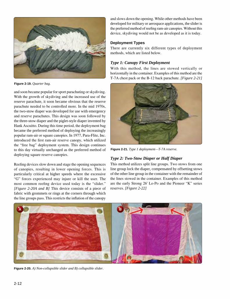
line. After deployment, the bag and static line remained with the aircraft. This system is still used today with some modifications. For emergency parachutes, the military adopted the “quarter bag” in the 1950s for use with high-speed emergency systems. [Figure 2-19] This was fairly complicated to pack but effective in controlling the parachute during opening. In the early 1960s, the sleeve was developed
2-12
Figure 2-19. Quarter bag.
Figure 2-21. Type 1 deployment—T-7A reserve.
Figure 2-20. A) Non-collapsible slider and B) collapsible slider.
and soon became popular for sport parachuting or skydiving. With the growth of skydiving and the increased use of the reserve parachute, it soon became obvious that the reserve parachute needed to be controlled more. In the mid 1970s, the two-stow diaper was developed for use with emergency and reserve parachutes. This design was soon followed by the three-stow diaper and the piglet-style diaper invented by Hank Ascuitto. During this time period, the deployment bag became the preferred method of deploying the increasingly popular ram-air or square canopies. In 1977, Para-Flite, Inc. introduced the first ram-air reserve canopy, which utilized the “free bag” deployment system. This design continues to this day virtually unchanged as the preferred method of deploying square reserve canopies.
Reefing devices slow down and stage the opening sequences of canopies, resulting in lower opening forces. This is particularly critical at higher speeds where the excessive “G” forces experienced may injure or kill the user. The most common reefing device used today is the “slider.” [Figure 2-20A and B] This device consists of a piece of fabric with grommets or rings at the corners through which the line groups pass. This restricts the inflation of the canopy
and slows down the opening. While other methods have been developed for military or aerospace applications, the slider is the preferred method of reefing ram-air canopies. Without this device, skydiving would not be as developed as it is today.
Deployment TypesThere are currently six different types of deployment methods, which are listed below.
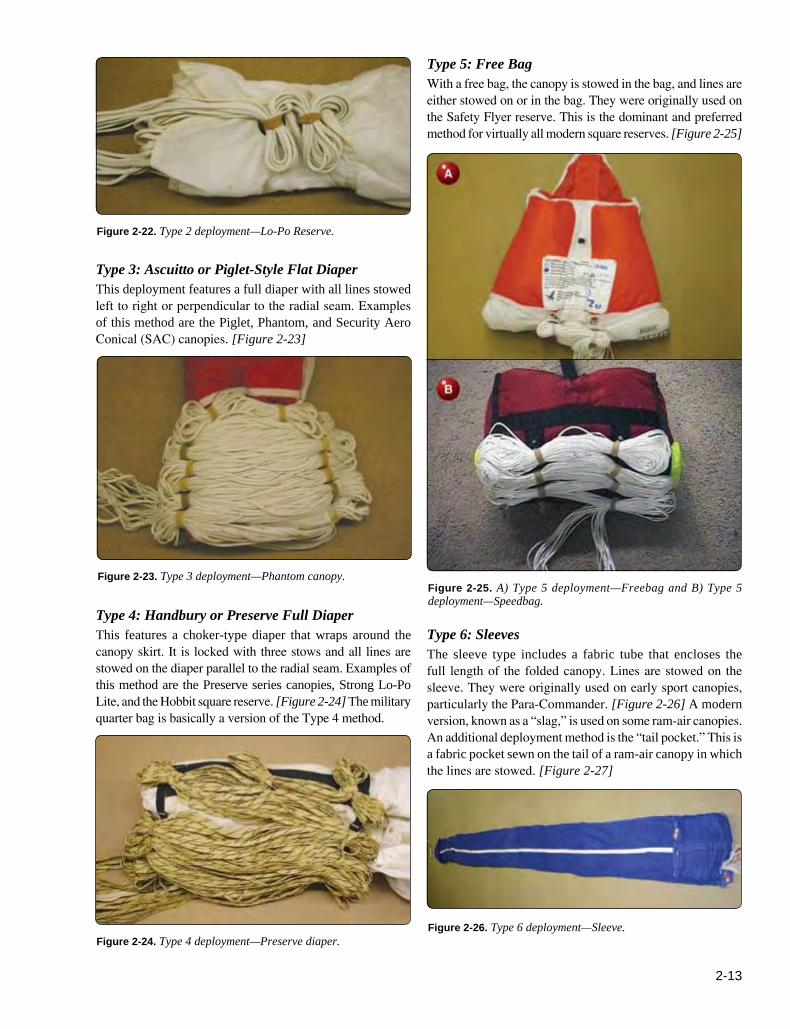
Type 1: Canopy First Deployment With this method, the lines are stowed vertically or horizontally in the container. Examples of this method are the T-7A chest pack or the B-12 back parachute. [Figure 2-21]
Type 2: Two-Stow Diaper or Half Diaper This method utilizes split line groups. Two stows from one line group lock the diaper, compensated by offsetting stows of the other line group in the container with the remainder of the lines stowed in the container. Examples of this method are the early Strong 26' Lo-Po and the Pioneer “K” series reserves. [Figure 2-22]
2-13
Figure 2-22. Type 2 deployment—Lo-Po Reserve.
Figure 2-23. Type 3 deployment—Phantom canopy.
Figure 2-24. Type 4 deployment—Preserve diaper.Figure 2-26. Type 6 deployment—Sleeve.
Figure 2-25. A) Type 5 deployment—Freebag and B) Type 5 deployment—Speedbag.
Type 3: Ascuitto or Piglet-Style Flat Diaper This deployment features a full diaper with all lines stowed left to right or perpendicular to the radial seam. Examples of this method are the Piglet, Phantom, and Security Aero Conical (SAC) canopies. [Figure 2-23]
Type 4: Handbury or Preserve Full Diaper This features a choker-type diaper that wraps around the canopy skirt. It is locked with three stows and all lines are stowed on the diaper parallel to the radial seam. Examples of this method are the Preserve series canopies, Strong Lo-Po Lite, and the Hobbit square reserve. [Figure 2-24] The military quarter bag is basically a version of the Type 4 method.
Type 5: Free Bag With a free bag, the canopy is stowed in the bag, and lines are either stowed on or in the bag. They were originally used on the Safety Flyer reserve. This is the dominant and preferred method for virtually all modern square reserves. [Figure 2-25]
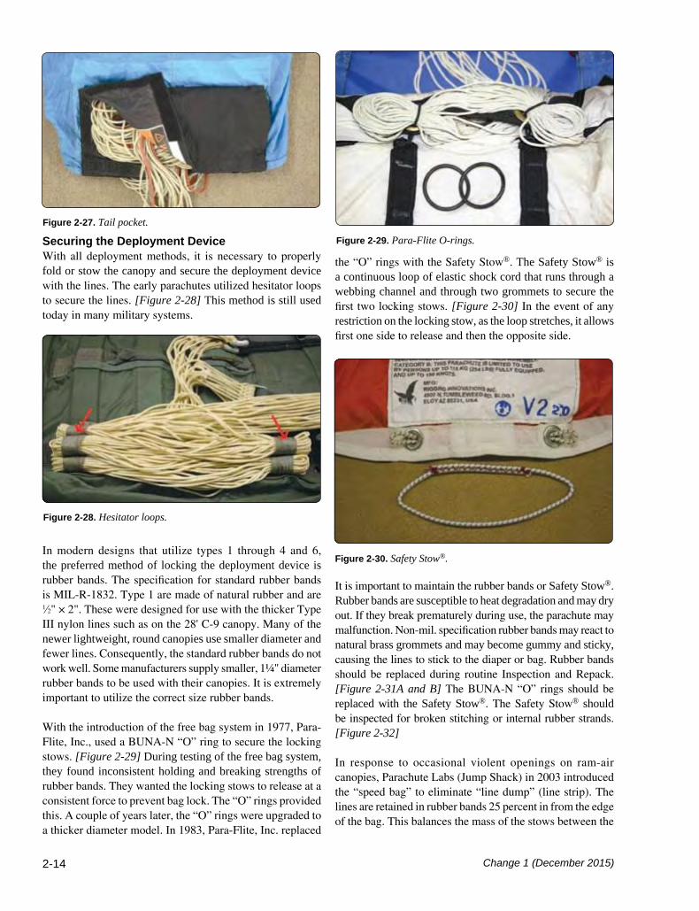
Type 6: SleevesThe sleeve type includes a fabric tube that encloses the full length of the folded canopy. Lines are stowed on the sleeve. They were originally used on early sport canopies, particularly the Para-Commander. [Figure 2-26] A modern version, known as a “slag,” is used on some ram-air canopies. An additional deployment method is the “tail pocket.” This is a fabric pocket sewn on the tail of a ram-air canopy in which the lines are stowed. [Figure 2-27]
2-14
Figure 2-30. Safety Stow®.
Figure 2-28. Hesitator loops.
Figure 2-29. Para-Flite O-rings.
Figure 2-27. Tail pocket.
Securing the Deployment Device With all deployment methods, it is necessary to properly fold or stow the canopy and secure the deployment device with the lines. The early parachutes utilized hesitator loops to secure the lines. [Figure 2-28] This method is still used today in many military systems.
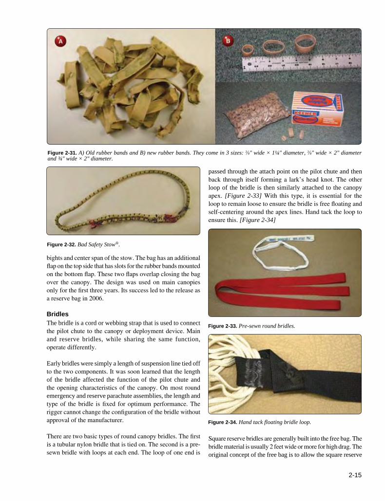
In modern designs that utilize types 1 through 4 and 6, the preferred method of locking the deployment device is rubber bands. The specification for standard rubber bands is MIL-R-1832. Type 1 are made of natural rubber and are 1⁄2" × 2". These were designed for use with the thicker Type III nylon lines such as on the 28' C-9 canopy. Many of the newer lightweight, round canopies use smaller diameter and fewer lines. Consequently, the standard rubber bands do not work well. Some manufacturers supply smaller, 1¼" diameter rubber bands to be used with their canopies. It is extremely important to utilize the correct size rubber bands.
With the introduction of the free bag system in 1977, Para-Flite, Inc., used a BUNA-N “O” ring to secure the locking stows. [Figure 2-29] During testing of the free bag system, they found inconsistent holding and breaking strengths of rubber bands. They wanted the locking stows to release at a consistent force to prevent bag lock. The “O” rings provided this. A couple of years later, the “O” rings were upgraded to a thicker diameter model. In 1983, Para-Flite, Inc. replaced
the “O” rings with the Safety Stow®. The Safety Stow® is a continuous loop of elastic shock cord that runs through a webbing channel and through two grommets to secure the first two locking stows. [Figure 2-30] In the event of any restriction on the locking stow, as the loop stretches, it allows first one side to release and then the opposite side.
It is important to maintain the rubber bands or Safety Stow®. Rubber bands are susceptible to heat degradation and may dry out. If they break prematurely during use, the parachute may malfunction. Non-mil. specification rubber bands may react to natural brass grommets and may become gummy and sticky, causing the lines to stick to the diaper or bag. Rubber bands should be replaced during routine Inspection and Repack. [Figure 2-31A and B] The BUNA-N “O” rings should be replaced with the Safety Stow®. The Safety Stow® should be inspected for broken stitching or internal rubber strands. [Figure 2-32]
In response to occasional violent openings on ram-air canopies, Parachute Labs (Jump Shack) in 2003 introduced the “speed bag” to eliminate “line dump” (line strip). The lines are retained in rubber bands 25 percent in from the edge of the bag. This balances the mass of the stows between the
Change 1 (December 2015)
2-15
Figure 2-32. Bad Safety Stow®.
Figure 2-31. A) Old rubber bands and B) new rubber bands. They come in 3 sizes: 3⁄8" wide × 1¼" diameter, 3⁄8" wide × 2" diameter and ¾" wide × 2" diameter.
Figure 2-34. Hand tack floating bridle loop.
Figure 2-33. Pre-sewn round bridles.
bights and center span of the stow. The bag has an additional flap on the top side that has slots for the rubber bands mounted on the bottom flap. These two flaps overlap closing the bag over the canopy. The design was used on main canopies only for the first three years. Its success led to the release as a reserve bag in 2006.
BridlesThe bridle is a cord or webbing strap that is used to connect the pilot chute to the canopy or deployment device. Main and reserve bridles, while sharing the same function, operate differently.
Early bridles were simply a length of suspension line tied off to the two components. It was soon learned that the length of the bridle affected the function of the pilot chute and the opening characteristics of the canopy. On most round emergency and reserve parachute assemblies, the length and type of the bridle is fixed for optimum performance. The rigger cannot change the configuration of the bridle without approval of the manufacturer.
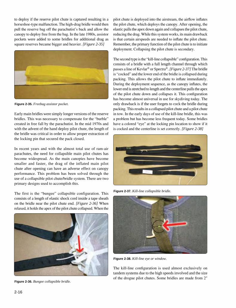
There are two basic types of round canopy bridles. The first is a tubular nylon bridle that is tied on. The second is a pre-sewn bridle with loops at each end. The loop of one end is
passed through the attach point on the pilot chute and then back through itself forming a lark’s head knot. The other loop of the bridle is then similarly attached to the canopy apex. [Figure 2-33] With this type, it is essential for the loop to remain loose to ensure the bridle is free floating and self-centering around the apex lines. Hand tack the loop to ensure this. [Figure 2-34]
Square reserve bridles are generally built into the free bag. The bridle material is usually 2 feet wide or more for high drag. The original concept of the free bag is to allow the square reserve
2-16
Figure 2-36. Bungee collapsible bridle.
Figure 2-37. Kill-line collapsible bridle.
Figure 2-38. Kill-line eye or window.
Figure 2-35. Freebag assistor pocket.
to deploy if the reserve pilot chute is captured resulting in a horseshoe-type malfunction. The high-drag bridle would then pull the reserve bag off the parachutist’s back and allow the canopy to deploy free from the bag. In the late 1980s, assistor pockets were added to some bridles for additional drag as square reserves became bigger and heavier. [Figure 2-35]
Early main bridles were simply longer versions of the reserve bridles. This was necessary to compensate for the “burble” created in free fall by the parachutist. In the mid 1970s and with the advent of the hand deploy pilot chute, the length of the bridle was critical in order to allow proper extraction of the locking pin that secured the pack closed.
In recent years and with the almost total use of ram-air parachutes, the need for collapsible main pilot chutes has become widespread. As the main canopies have become smaller and faster, the drag of the inflated main pilot chute after opening can have an adverse effect on canopy performance. This problem has been solved through the use of a collapsible pilot chute/bridle system. There are two primary designs used to accomplish this.
The first is the “bungee” collapsible configuration. This consists of a length of elastic shock cord inside a tape sheath on the bridle near the pilot chute end. [Figure 2-36] When relaxed, it holds the apex of the pilot chute collapsed. When the
pilot chute is deployed into the airstream, the airflow inflates the pilot chute, which deploys the canopy. After opening, the elastic pulls the apex down again and collapses the pilot chute, reducing the drag. While this system works, its main drawback is that certain airspeeds are needed to inflate the pilot chute. Remember, the primary function of the pilot chute is to initiate deployment. Collapsing the pilot chute is secondary.
The second type is the “kill-line collapsible” configuration. This consists of a bridle with a full length channel through which passes a line of Kevlar® or Spectra®. [Figure 2-37] The bridle is “cocked” and the lower end of the bridle is collapsed during packing. This allows the pilot chute to inflate immediately. During the deployment sequence, as the canopy inflates, the lower end is stretched to length and the centerline pulls the apex of the pilot chute down and collapses it. This configuration has become almost universal in use for skydiving today. The only drawback is if the user forgets to cock the bridle during packing. This results in a collapsed pilot chute and a pilot chute in tow. In the early days of use of the kill-line bridle, this was a problem but has become less frequent today. Some bridles have a colored “eye” at the locking pin location to show if it is cocked and the centerline is set correctly. [Figure 2-38]
The kill-line configuration is used almost exclusively on tandem systems due to the high speeds involved and the size of the drogue pilot chutes. Some bridles are made from 2"

2-17
Figure 2-39. Tandem main collapsible bridle.
Kevlar® tape and have tubular nylon centerlines. Others are made from Type 4 square weave with a Spectra centerline. The advantage of the latter is that it can be cut with a hook knife in the event of an on-person malfunction. [Figure 2-39]
Another method of collapsing the pilot chute is to install a No. 8 grommet in the deployment bag and allow the bag to float on the bridle. After the canopy deploys, the bag slides up the bridle, inverts, and covers the pilot chute. This is commonly called the “poor man’s collapsible pilot chute system.” The drawback to this design is the high wear on the bridle and pilot chute mesh.
Pilot Chutes A pilot chute is a small parachute that is used to deploy the main or reserve parachute. In the earliest uses of parachutes, the parachute was static line deployed. With the advent of manually operated or “free fall” parachutes, the need for a pilot chute was quickly recognized.
There are two basic types of pilot chutes. The first is the spring-loaded design. This uses a collapsible spring, which is compressed in the parachute container and held closed with the ripcord. When the ripcord is pulled, the pack opens and the pilot chute launches into the airstream. The pilot chute provides drag and pulls the canopy from the pack as the parachutist or load falls away. During this process, the pilot chute also provides tension on the lines of the deploying canopy and helps the opening sequence. Spring-loaded pilot chutes are used primarily for emergency and reserve parachutes. In addition, they are used in military free fall and training systems for the main parachute.
The second type of pilot chute is the “hand deploy” design. This type consists of the pilot chute canopy but does not have a spring to launch it. Instead, the parachutist extracts the folded pilot chute from a pouch or the container and launches
it into the airstream. The pack is held closed by a locking pin attached to the bridle of the pilot chute. As the pilot chute inflates, it extracts the pin from the locking loop and pulls the parachute from the pack. The rest of the opening process is similar to the spring-loaded pilot chute. This configuration came into popularity in the mid 1970s and is now the primary method of deployment in skydiving.
Spring-Loaded Pilot ChutesSpring-loaded pilot chutes date from the 1920s. However, it was not until 1940 that the spiral vane pilot chute was invented. This design used a spiral spring that is easy to collapse and pack. The most common type of spiral vane pilot chute used today is the MA-1 model. [Figure 2-40A and B] This is used in several military parachute assemblies. In the early days of skydiving, military pilot chutes, such as the MA-1 and others were popular. Soon commercial designs were introduced that improved on the MA-1 with better launch and drag characteristics. These included the Grabber® and Hot Dog® pilot chutes. Both of these were primarily for use with main parachutes.
With the advent of the hand deploy pilot chute for the main, most of the improvement in spring-loaded pilot chute design has focused on its use in the reserve or emergency parachutes. This has paralleled the improvements in container design and the increased use of AADs. Both of these require better pilot chutes than in the past.
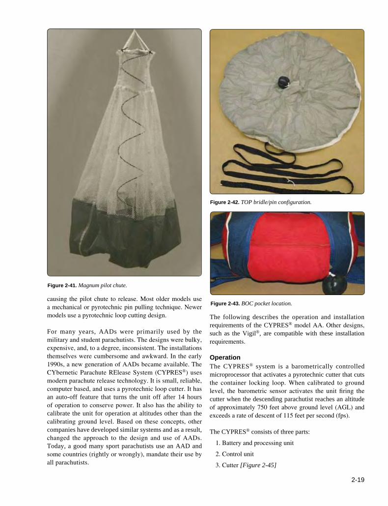
One example for reserve use is the Magnum® pilot chute designed by National Parachute Industries. [Figure 2-41] With its unique shape, it provides maximum drag at low speeds, such as are experienced during cutaways. Its design has been licensed by other manufacturers for use in their assemblies. Additional designs include the Vector II reserve pilot chute and the Stealth pilot chute. The Vector II design is a “ballute” configuration that eliminates the use of mesh. In the event of an unstable launch on its side, the mass of fabric is sufficient to lift the pilot chute and deploy the parachute. The Stealth pilot chute uses a conventional mesh design but has a unique spring/cap configuration that allows the pilot chute to virtually disappear when packed, hence the name. The MA-1 spring with mesh in place of the vanes, and a closed canopy instead of the scalloped canopy provides the best of both worlds: a spring that does not lock up on itself and high drag without the possibility of snag.
Hand Deploy Pilot Chutes The hand deploy pilot chute was introduced in 1976. There are two types of hand deploy designs. One is the throw-out pilot chute (TOP) configuration. This is the type where the pilot chute pulls the locking pin located on the bridle. [Figure 2-42] The original design had the pilot chute pouch

2-18
Figure 2-40. A) MA-1 pilot chute and B) high-drag pilot chute with large hole mesh.
mounted on the belly band. Today, the primary location is an elastic/Spandex® pocket mounted on the bottom of the main container (BOC). [Figure 2-43] Most of the difficulties of this design have to do with pilot chute in tow due to misrouting of the bridle or failure of the pin to extract.
The second type is the pull-out pilot chute (POP) configuration. This design has the pilot chute packed in the container, which is locked with a straight locking pin attached to a short lanyard and handle. [Figure 2-44A and B] This handle is usually mounted on the bottom corner of the main container. The parachutist grasps the handle and pulls the locking pin from the locking loop and puts the pilot chute into the airstream. The handle is usually attached to the bottom of the pilot chute and as the chute enters the airstream, the jumper loosens his grip on the handle allowing it to be pulled from his or her hand. This makes for a positive deployment. The main drawback to this system is losing the handle due to it being dislodged while
moving around in the aircraft or in the air. Fortunately, the handle does not go far and is easy to obtain because it is on a short lanyard that is tucked up under the side flap. .
Automatic Activation Devices (AADs) and Reserve Static Lines (RSLs) Safety considerations have led to the development of AADs and reserve static line (RSL) systems. These devices allow for automatic deployment of the main or reserve parachutes in the event of an emergency.
Automatic Activation Devices AADs are devices that activate the parachute automatically. Modern systems combine a barometric sensor with a rate of descent sensor so that the system is fully automatic once turned on and calibrated. The activation may be by either pulling the ripcord pin(s) or cutting the locking loop(s),
2-19
Figure 2-41. Magnum pilot chute.
Figure 2-42. TOP bridle/pin configuration.
Figure 2-43. BOC pocket location.causing the pilot chute to release. Most older models use a mechanical or pyrotechnic pin pulling technique. Newer models use a pyrotechnic loop cutting design.
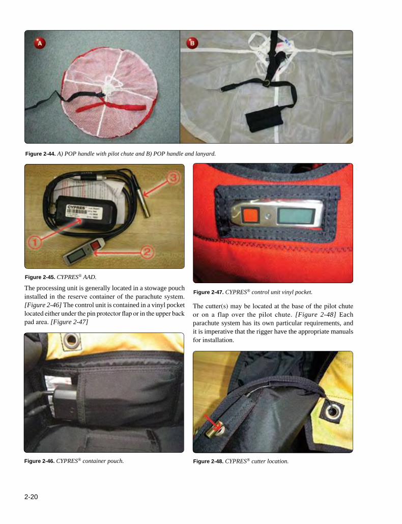
For many years, AADs were primarily used by the military and student parachutists. The designs were bulky, expensive, and, to a degree, inconsistent. The installations themselves were cumbersome and awkward. In the early 1990s, a new generation of AADs became available. The CYbernetic Parachute RElease System (CYPRES®) uses modern parachute release technology. It is small, reliable, computer based, and uses a pyrotechnic loop cutter. It has an auto-off feature that turns the unit off after 14 hours of operation to conserve power. It also has the ability to calibrate the unit for operation at altitudes other than the calibrating ground level. Based on these concepts, other companies have developed similar systems and as a result, changed the approach to the design and use of AADs. Today, a good many sport parachutists use an AAD and some countries (rightly or wrongly), mandate their use by all parachutists.
The following describes the operation and installation requirements of the CYPRES® model AA. Other designs, such as the Vigil®, are compatible with these installation requirements.
OperationThe CYPRES® system is a barometrically controlled microprocessor that activates a pyrotechnic cutter that cuts the container locking loop. When calibrated to ground level, the barometric sensor activates the unit firing the cutter when the descending parachutist reaches an altitude of approximately 750 feet above ground level (AGL) and exceeds a rate of descent of 115 feet per second (fps).
The CYPRES® consists of three parts:
1. Battery and processing unit
2. Control unit
3. Cutter [Figure 2-45]
2-20
Figure 2-45. CYPRES® AAD.
Figure 2-44. A) POP handle with pilot chute and B) POP handle and lanyard.
Figure 2-46. CYPRES® container pouch.
Figure 2-47. CYPRES® control unit vinyl pocket.
Figure 2-48. CYPRES® cutter location.
The processing unit is generally located in a stowage pouch installed in the reserve container of the parachute system. [Figure 2-46] The control unit is contained in a vinyl pocket located either under the pin protector flap or in the upper back pad area. [Figure 2-47]
The cutter(s) may be located at the base of the pilot chute or on a flap over the pilot chute. [Figure 2-48] Each parachute system has its own particular requirements, and it is imperative that the rigger have the appropriate manuals for installation.
2-21
Figure 2-49. Single-side RSL configuration.
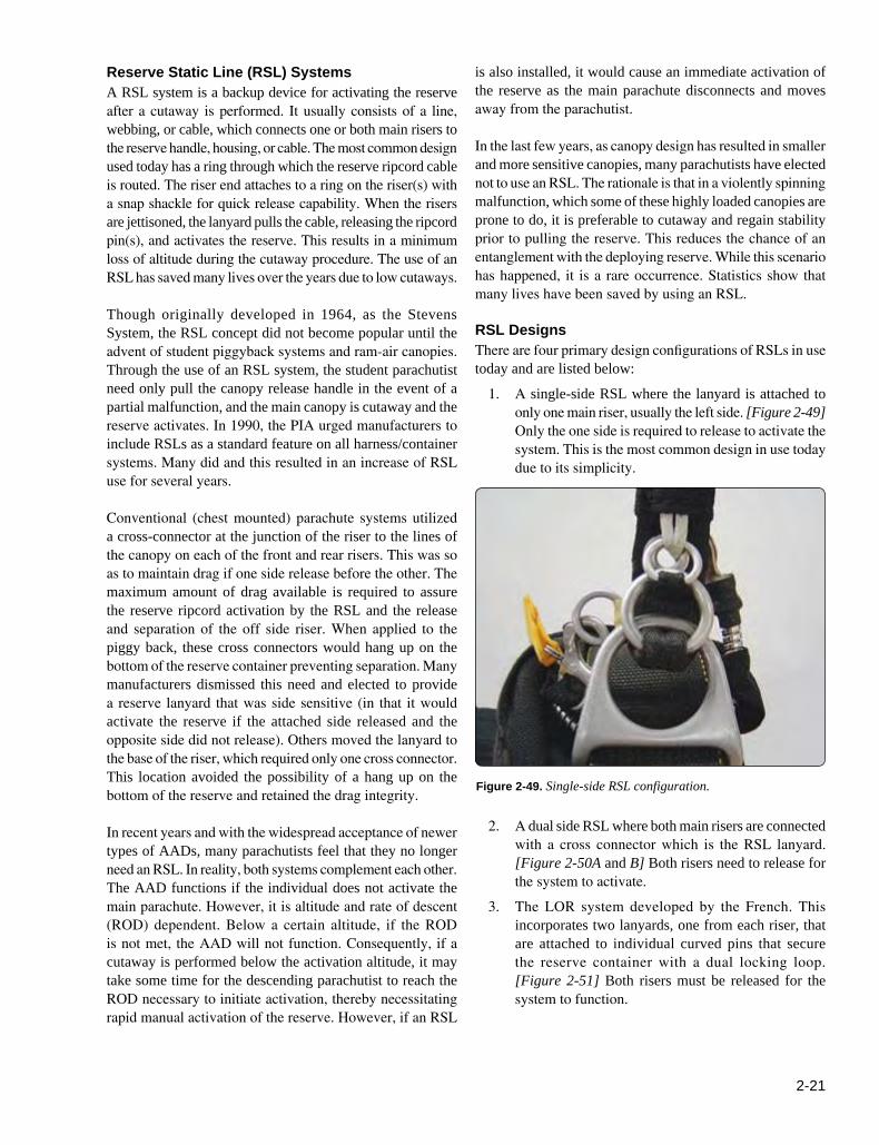
Reserve Static Line (RSL) Systems A RSL system is a backup device for activating the reserve after a cutaway is performed. It usually consists of a line, webbing, or cable, which connects one or both main risers to the reserve handle, housing, or cable. The most common design used today has a ring through which the reserve ripcord cable is routed. The riser end attaches to a ring on the riser(s) with a snap shackle for quick release capability. When the risers are jettisoned, the lanyard pulls the cable, releasing the ripcord pin(s), and activates the reserve. This results in a minimum loss of altitude during the cutaway procedure. The use of an RSL has saved many lives over the years due to low cutaways.
Though originally developed in 1964, as the Stevens System, the RSL concept did not become popular until the advent of student piggyback systems and ram-air canopies. Through the use of an RSL system, the student parachutist need only pull the canopy release handle in the event of a partial malfunction, and the main canopy is cutaway and the reserve activates. In 1990, the PIA urged manufacturers to include RSLs as a standard feature on all harness/container systems. Many did and this resulted in an increase of RSL use for several years.
Conventional (chest mounted) parachute systems utilized a cross-connector at the junction of the riser to the lines of the canopy on each of the front and rear risers. This was so as to maintain drag if one side release before the other. The maximum amount of drag available is required to assure the reserve ripcord activation by the RSL and the release and separation of the off side riser. When applied to the piggy back, these cross connectors would hang up on the bottom of the reserve container preventing separation. Many manufacturers dismissed this need and elected to provide a reserve lanyard that was side sensitive (in that it would activate the reserve if the attached side released and the opposite side did not release). Others moved the lanyard to the base of the riser, which required only one cross connector. This location avoided the possibility of a hang up on the bottom of the reserve and retained the drag integrity.
In recent years and with the widespread acceptance of newer types of AADs, many parachutists feel that they no longer need an RSL. In reality, both systems complement each other. The AAD functions if the individual does not activate the main parachute. However, it is altitude and rate of descent (ROD) dependent. Below a certain altitude, if the ROD is not met, the AAD will not function. Consequently, if a cutaway is performed below the activation altitude, it may take some time for the descending parachutist to reach the ROD necessary to initiate activation, thereby necessitating rapid manual activation of the reserve. However, if an RSL
is also installed, it would cause an immediate activation of the reserve as the main parachute disconnects and moves away from the parachutist.
In the last few years, as canopy design has resulted in smaller and more sensitive canopies, many parachutists have elected not to use an RSL. The rationale is that in a violently spinning malfunction, which some of these highly loaded canopies are prone to do, it is preferable to cutaway and regain stability prior to pulling the reserve. This reduces the chance of an entanglement with the deploying reserve. While this scenario has happened, it is a rare occurrence. Statistics show that many lives have been saved by using an RSL.
RSL DesignsThere are four primary design configurations of RSLs in use today and are listed below:
1. A single-side RSL where the lanyard is attached to only one main riser, usually the left side. [Figure 2-49] Only the one side is required to release to activate the system. This is the most common design in use today due to its simplicity.
2. A dual side RSL where both main risers are connected with a cross connector which is the RSL lanyard. [Figure 2-50A and B] Both risers need to release for the system to activate.
3. The LOR system developed by the French. This incorporates two lanyards, one from each riser, that are attached to individual curved pins that secure the reserve container with a dual locking loop. [Figure 2-51] Both risers must be released for the system to function.

2-22
Figure 2-50. A) Dual-side RSL configuration and B) dual-RSL routing diagram.
Figure 2-51. LOR system.
Figure 2-52. Skyhook® system.
Collin’s Landyard Loop
4. The Collins Lanyard/Skyhook™ system. This design utilizes a special lanyard that is attached to the bridle of the reserve free bag. [Figure 2-52] Cutting away results in the free bag being pulled directly out of the container by the main risers and results in very little altitude loss.
Since the early 1990s, most (if not all) manufacturers have provided an RSL installation on their equipment either as standard or optional. If the rigger has a system without an RSL
and the owner wishes to have one installed, the rigger should check with the manufacturer as to the availability of a retrofit kit or return it to the manufacturer for installation. Because the installation of an RSL is an alteration to the original design, the rigger needs approval either from the manufacturer or the FAA.
Because of the nature of the RSL system, it is imperative that the rigger thoroughly understands the individual concepts. Unless he or she understands this and has the required manufacturer’s instructions, the rigger should not attempt to assemble and pack a system with an RSL installation. The following describes the basic design and function of a single side RSL installation on a one-pin reserve container.
Main Riser AttachmentThe main risers must have an attachment location for the lanyard. In this example, a small ring is installed near the lower hardware end of the riser on the inboard side. [Figure 2-53] It is

2-23
Figure 2-54. Snap shackle on RSL lanyard.
Figure 2-53. Main riser RSL ring attachment.
Figure 2-55. Double-ring container installation.desirable to locate the ring as close to the lower end as possible so that the pivot arc of the rise does not load the lanyard. This allows the riser end of the lanyard end to be as short as possible. If there is excess lanyard, it is difficult to stow, and it is possible for the lanyard to become snagged and unseated. It is important that the correct risers with attachment ring be installed. While many risers have a ring installation, not all are installed at the correct location. Consequently, the lanyard length will not match the factory dimensions. This can result in premature reserve activation when the main is deployed.
Most RSL lanyard designs have a snap shackle or similar release device mounted at the riser end of the lanyard. [Figure 2-54] This allows the user to disconnect the lanyard under certain circumstances. The most common one involves landing in
high winds where the parachutist may wish to cutaway the main canopy to prevent being dragged. If the lanyard were not released, the reserve would be deployed as the main is cutaway.
Ripcord Cable Routing The routing of the ripcord cable from the handle to the pin determines where the lanyard connects to the cable. Most RSL attachments connect with the ripcord cable either at the yoke area or just above the ripcord pin. Generally, there is a double ring installation where the cable end of the lanyard is located. [Figure 2-55] On this particular installation, the connection is at the shoulder yoke area.
RSL Lanyard and Container Mount These two components are interactive. That is, the design of the container directly affects the design of the lanyard. Once the two above locations are determined, then the routing of the lanyard can be completed. It was originally thought that the lanyard should have a long length to allow acceleration during activation to pull the ripcord cable. This has not proven to be true and most manufacturers keep their lanyards as short as possible to prevent snagging and easier stowing. The Racer cross-connector/lanyard is so sized as to not pull the reserve ripcord until both risers have separated
In the past, a Velcro® pathway was used for routing the lanyard. This was either on the shoulder yoke or the reserve riser. Experience has shown that the use of Velcro® generally results in high wear and eventual damage to the webbing. [Figure 2-56] On this design, the lanyard is stiffened with a short piece of coated cable and stowed in two pockets located on the yoke area. [Figure 2-57] It is secure and has no wear points. The ripcord end of the lanyard is routed to the dual guide ring attachment location and the ripcord cable routed through the rings. [Figure 2-58] The ripcord cable is then routed to the reserve closing loop. Figure 2-59 shows the RSL lanyard and ripcord cable at the moment of riser extension and just as the cable is loaded. A point that the rigger should be

2-24
Figure 2-57. One style of RSL lanyard without Velcro.
Figure 2-58. Ripcord cable routing through rings.
Figure 2-61. Cutaway cable length differential.
Figure 2-59. RSL lanyard extension.
Figure 2-60. Ripcord cable pigtail with broken strand.
Figure 2-56. RSL Velcro riser damage.
aware of is the “pigtail” configuration of the reserve ripcord that results from the use of the RSL. [Figure 2-60] Because of the sliding of the ring along the ripcord cable, a curling effect is imparted to the cable. This is a clear indication that the RSL lanyard activated the reserve. The rigger should carefully inspect the ripcord cable for any broken strands. If any are found, the ripcord should be replaced. If not, the cable can be straightened and returned to service.
With the single side RSL, it is imperative that the main riser with the RSL attachment leave after the opposite riser. If the opposite riser stays connected while the RSL
deploys the reserve, there is the possibility of a main/reserve entanglement. To ensure the correct staging of the cutaway, the release cable of the RSL side must be longer than the cable on the opposite riser. A minimum of 1 inch is the standard differential. [Figure 2-61] If non-compressible housings are not used, the staged separation is not reliable.
Joint EfficiencyJoint efficiency is the percentage of the measurement of strength when applied to the junction or fabrication of two or more materials. An example is the cross seam in a canopy gore where two panels of fabric are joined. The strength of the seam needs to be greater than the strength of the fabric.

2-25
To achieve this, there are several factors that need to be considered in the design. These include the following:
• Fabric—the weight and weave of the fabric affects the type of junction used.
• Thread type—this is affected by the weight of the fabric. Generally, the lighter the fabric, the smaller the thread used. Accordingly, a smaller needle is used in order not to damage the weave of the fabric.
• Stitch type—this is determined by the type of seam needed for the design. For the French fell seam normally used in joining the panels of a canopy, the 301 straight stitch is used.
• Stitches per inch—this has a direct correlation to the size of the thread used and the stitch type. There is a fine balance between the security of the seam and overstitching. Too many stitches per inch dramatically affects the strength of the seam by perforating the material. The number of rows of stitching also affects this. While more rows generally increase the strength of the seam, too many perforate the material as well.
• Thread tension—as lighter fabric and thread are used, the thread tension balance becomes more important.
• Reinforcing—the addition of reinforcing through the use of tapes, cords, etc., adds to the strength of the seam. However, their use may also reduce the elasticity of the seam at the same time.
Some of the previous factors also can affect heavier materials, such as tapes and webbings. In working with webbings in harness design, most construction methods have tended to overbuild the junctions. This has been done primarily because the materials have readily accepted heavier threads and stitch patterns.
An area that needs to be addressed is that of re-stitching webbing. Until recently, there was not much study done to determine how much strength is lost in this process. G.S. Dunker, a parachute engineer, conducted a study that evaluated the variables introduced when re-stitching webbing junctions. Some of these variables included the following:
• The treatment or conditioning of the webbing. Condition R webbing has a resin treatment to make it stiffer as opposed to condition U or untreated webbing.
• The size and condition of the needle used in the sewing. Larger needles make larger holes. A blunt needle or one whose point is damaged, will do more damage to the webbing and weaken it.
• The size of the thread used.
• The stitch pattern used and length. A W–W pattern is stronger than a box X pattern.
• The number of times the webbing is re-sewn.
All of these affect the ultimate strength of the webbing junction or stitch pattern.
Chapter SummaryIt is important to know the history of parachute design in order to move forward technologically. The old saying, “Those who don’t know history are destined to repeat it.” Is especially applicable to parachute design and manufacture, where a relatively small, esoteric group of individuals who are loosely controlled and turn on a dime, churn out designs that some eager young test jumper is willing to try. This is not necessarily a bad thing. The civilian led sport parachute market is responsible for just about all the newest innovations in the industry over the past 45 years. But it should be kept in mind that a new design generally takes about ten years’ wringing out in the field to discover it’s failure modes and make it safe and reliable.

2-26
3-1
MaterialsChapter 3
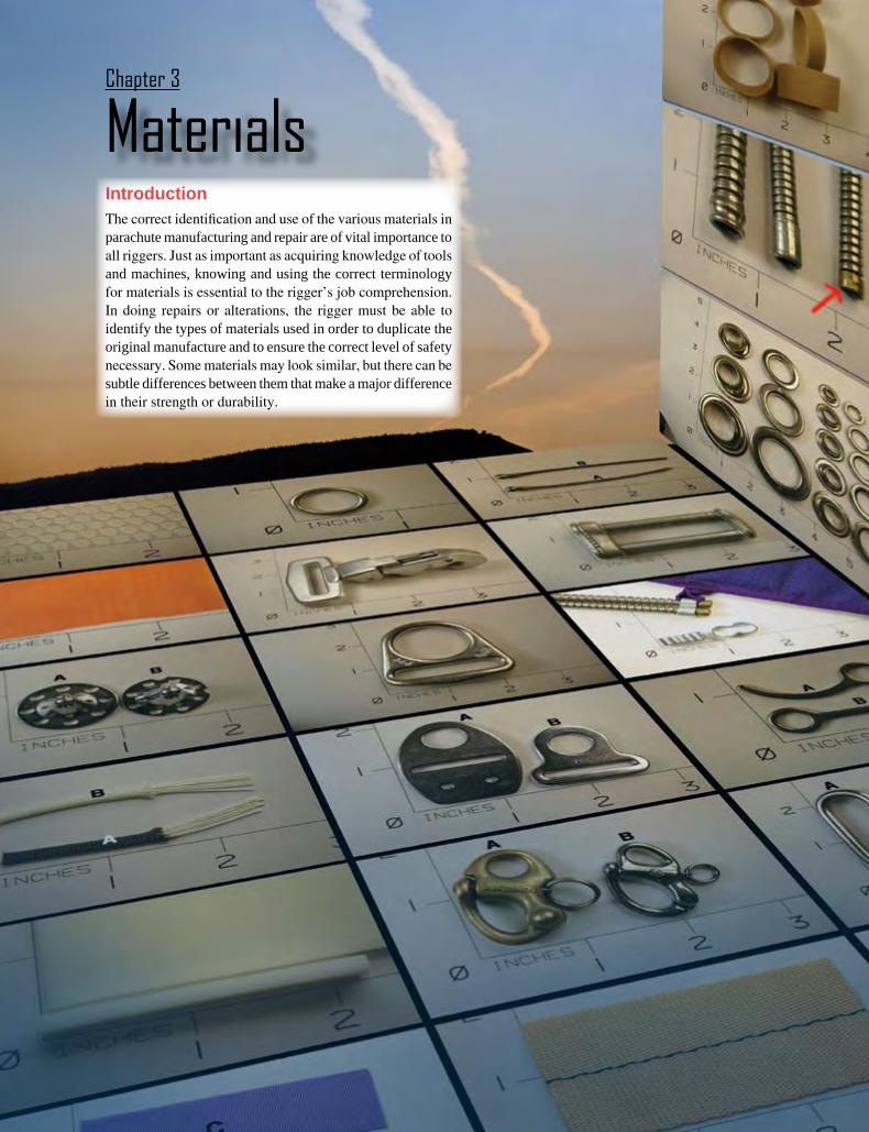
IntroductionThe correct identification and use of the various materials in parachute manufacturing and repair are of vital importance to all riggers. Just as important as acquiring knowledge of tools and machines, knowing and using the correct terminology for materials is essential to the rigger’s job comprehension. In doing repairs or alterations, the rigger must be able to identify the types of materials used in order to duplicate the original manufacture and to ensure the correct level of safety necessary. Some materials may look similar, but there can be subtle differences between them that make a major difference in their strength or durability.

3-2
It is not the intent of this chapter to present information on every type of material or hardware ever used in parachutes. For very detailed specifications on a broader range of materials used in current production parachutes, as well as obsolete and military surplus parachutes, there are additional reference sources, such as “The Parachute Manual” by Dan Poynter. The purpose of this chapter is to present as much information on the essentials of modern materials seen in today’s parachute systems.
Many riggers operate quite successfully with a basic level of material knowledge in their proverbial tool kit. There are certain materials that are commonly used on most parachute systems, and in dealing with these on a regular basis, the rigger becomes very familiar with their characteristics and proper application. It is fundamental that the rigger know their correct type, nomenclature, strength, and common use. In dealing with other riggers, manufacturers, and suppliers, the rigger is then able to identify the referenced material in order to obtain the appropriate repair part or describe the use of the material to others. All of this is part of the parachute rigger’s lexicon, required to communicate their needs and accomplish the required tasks.
SpecificationsAll certificated parachute systems built under government approval programs require most, if not all, materials used in their construction to have some form of specification approval. The most common of these systems is the military specification (MIL-SPEC) system. In addition, there are other government specifications, such as Federal Standards, and commercial specifications in use. The MIL-SPEC system is the one with which most riggers are familiar. Contrary to popular perception, not all materials for use in parachute manufacturing must be MIL-SPEC. Any specification may be used, provided that the manufacturer can prove compliance with this specification, and that the specification is acceptable to the Federal Aviation Administration (FAA) for use in the parachute system. As a rule, the MIL-SPEC system has proven the most readily available and accepted method.
In recent years, the government has been accepting more commercial specifications in lieu of MIL-SPEC items. In 2002, the Parachute Industry Association (PIA) adopted approximately 270 parachute-related specifications, drawings, standards, and test methods. The PIA takes responsibility for the continued maintenance and revision of these specifications. As the specifications are revised, they keep their original identification number, but the PIA prefix precedes them. For instance, MIL-W-4088 webbing becomes PIA-W-4088. Through the involvement of the PIA Specifications Committee, the revised specifications, including new digital drawings, are made available to the industry.
The MIL-SPEC or PIA-SPEC system of identification consists of the initial letters MIL or PIA with a middle letter such as W for webbing or wire, then the identification or serial number of the specification. In addition, there may be a revision letter, such as A, B, C, D, etc. In the case of PIA-W-4088D, this is the fourth revision.
The materials and hardware listed herein are only a small part of those available, but the most commonly used in the majority of today’s rigging profession. By learning the specifications and uses of these materials, the rigger establishes a sound basis for the repair and maintenance of modern parachutes.
To promote the latest specifications, the PIA nomenclature is called out unless otherwise noted. In the past, the common method to denote the various types of webbings, cords, etc., was to use the Roman numeral for the type (e.g., Type VIII for Ty-8, Type XVII for Ty-17). For this handbook, the standard is the Arabic numeral (e.g., Ty-7).
Many of the figures in this chapter use a neutral background with an XY grid for reference. The numbers are in one-inch increments for a proportional reference.
FabricsNylon is the predominate fabric used in the manufacture of parachutes. Chemically speaking, nylon is made of repeating units linked by amide bonds and is frequently referred to as a polyamide (PA). It was invented in the late 1930s by Wallace Carothers while conducting research at DuPont. There are many different kinds of nylon and some of the major differences include the weave, weight, and finish. The various types of materials include canopy fabric, pack cloth, tapes, webbings, mesh, elastic fabrics, stiffener materials, and foams.
Canopy fabrics are primarily ripstop nylon. Ripstop weave is a plain weave with heavier threads woven into the material at right angles resulting in a boxlike pattern. The heavier thread and the unique weave results in ability of the threads to slide over one another inhibiting the tearing process and results in stronger fabrics. [Figures 3-1 through 3-6]
The composition of most containers is from either nylon duck (Para-pack) or Cordura®. Para-pack has a smooth somewhat shiny finish; Cordura has a matte, more rugged appearance. Both are sturdy and long lasting. Most sport containers also utilize a thin foam lining on the inside of the flaps to smooth out the fabric and absorb wear and tear. Other fabrics, such as mesh, Spandex®, and ballistic fabric, serve specialized purposes. [Figures 3-7 through 3-16]
3-3
Specification:Tear/breaking Strength:Identification:Common Use:Comment:
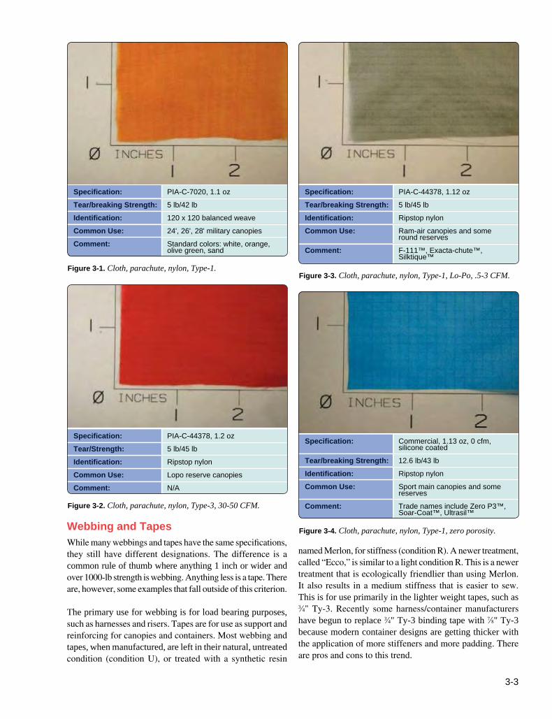
PIA-C-7020, 1.1 oz5 lb/42 lb120 x 120 balanced weave24', 26', 28' military canopiesStandard colors: white, orange, olive green, sand
Specification:Tear/breaking Strength:Identification:Common Use:
Comment:
PIA-C-44378, 1.12 oz5 lb/45 lbRipstop nylonRam-air canopies and some round reservesF-111™, Exacta-chute™, Silktique™
Specification:Tear/Strength:Identification:Common Use:Comment:
PIA-C-44378, 1.2 oz5 lb/45 lbRipstop nylonLopo reserve canopiesN/A
Specification:
Tear/breaking Strength:Identification:Common Use:
Comment:
Commercial, 1.13 oz, 0 cfm, silicone coated12.6 lb/43 lbRipstop nylonSport main canopies and some reservesTrade names include Zero P3™, Soar-Coat™, Ultrasil™
Figure 3-1. Cloth, parachute, nylon, Type-1. Figure 3-3. Cloth, parachute, nylon, Type-1, Lo-Po, .5-3 CFM.
Figure 3-2. Cloth, parachute, nylon, Type-3, 30-50 CFM.
Figure 3-4. Cloth, parachute, nylon, Type-1, zero porosity.Webbing and TapesWhile many webbings and tapes have the same specifications, they still have different designations. The difference is a common rule of thumb where anything 1 inch or wider and over 1000-lb strength is webbing. Anything less is a tape. There are, however, some examples that fall outside of this criterion.
The primary use for webbing is for load bearing purposes, such as harnesses and risers. Tapes are for use as support and reinforcing for canopies and containers. Most webbing and tapes, when manufactured, are left in their natural, untreated condition (condition U), or treated with a synthetic resin
named Merlon, for stiffness (condition R). A newer treatment, called “Ecco,” is similar to a light condition R. This is a newer treatment that is ecologically friendlier than using Merlon. It also results in a medium stiffness that is easier to sew. This is for use primarily in the lighter weight tapes, such as 3⁄4" Ty-3. Recently some harness/container manufacturers have begun to replace 3⁄4" Ty-3 binding tape with 7⁄8" Ty-3 because modern container designs are getting thicker with the application of more stiffeners and more padding. There are pros and cons to this trend.
3-4
Specification:Tear/breaking Strength:Identification:Common Use:Comment:
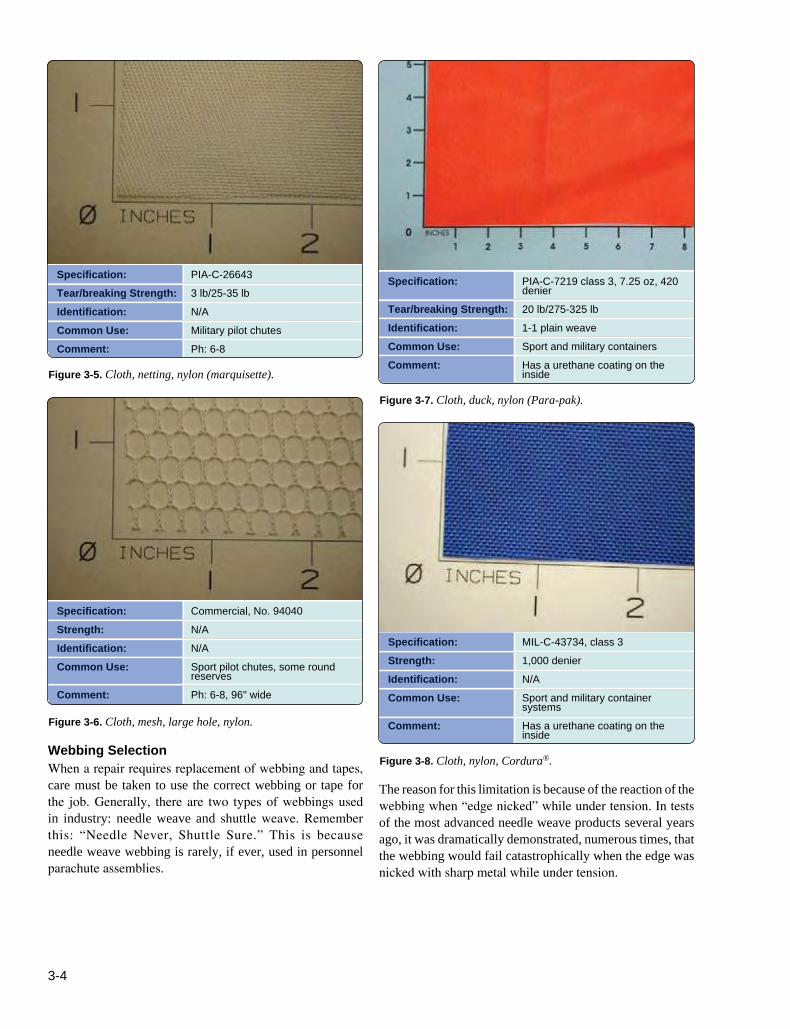
PIA-C-266433 lb/25-35 lbN/AMilitary pilot chutesPh: 6-8
Specification:
Tear/breaking Strength:Identification:Common Use:Comment:
PIA-C-7219 class 3, 7.25 oz, 420 denier20 lb/275-325 lb1-1 plain weaveSport and military containersHas a urethane coating on the inside
Specification:Strength:Identification:Common Use:
Comment:
Commercial, No. 94040N/AN/ASport pilot chutes, some round reservesPh: 6-8, 96" wide
Specification:Strength:Identification:Common Use:
Comment:
MIL-C-43734, class 31,000 denierN/ASport and military container systemsHas a urethane coating on the inside
Figure 3-5. Cloth, netting, nylon (marquisette).
Figure 3-7. Cloth, duck, nylon (Para-pak).
Figure 3-6. Cloth, mesh, large hole, nylon.
Figure 3-8. Cloth, nylon, Cordura®.
The reason for this limitation is because of the reaction of the webbing when “edge nicked” while under tension. In tests of the most advanced needle weave products several years ago, it was dramatically demonstrated, numerous times, that the webbing would fail catastrophically when the edge was nicked with sharp metal while under tension.
Webbing SelectionWhen a repair requires replacement of webbing and tapes, care must be taken to use the correct webbing or tape for the job. Generally, there are two types of webbings used in industry: needle weave and shuttle weave. Remember this: “Needle Never, Shuttle Sure.” This is because needle weave webbing is rarely, if ever, used in personnel parachute assemblies.
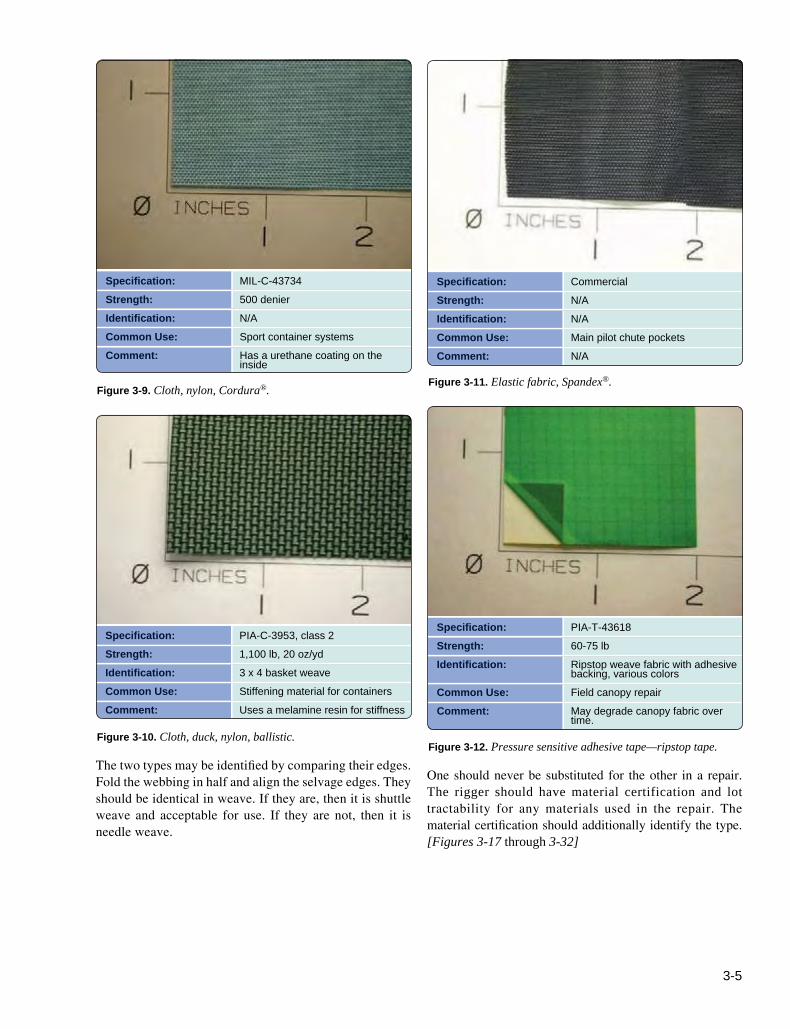
3-5
Specification:Strength:Identification:Common Use:Comment:
MIL-C-43734500 denierN/ASport container systemsHas a urethane coating on the inside
Specification:Strength:Identification:Common Use:Comment:
CommercialN/AN/AMain pilot chute pocketsN/A
Specification:Strength:Identification:Common Use:Comment:
PIA-C-3953, class 21,100 lb, 20 oz/yd3 x 4 basket weaveStiffening material for containersUses a melamine resin for stiffness
Specification:Strength:Identification:
Common Use:Comment:
PIA-T-4361860-75 lbRipstop weave fabric with adhesive backing, various colorsField canopy repairMay degrade canopy fabric over time.
Figure 3-9. Cloth, nylon, Cordura®. Figure 3-11. Elastic fabric, Spandex®.
Figure 3-10. Cloth, duck, nylon, ballistic. Figure 3-12. Pressure sensitive adhesive tape—ripstop tape.
One should never be substituted for the other in a repair. The rigger should have material certification and lot tractability for any materials used in the repair. The material certification should additionally identify the type. [Figures 3-17 through 3-32]
The two types may be identified by comparing their edges. Fold the webbing in half and align the selvage edges. They should be identical in weave. If they are, then it is shuttle weave and acceptable for use. If they are not, then it is needle weave.

3-6
Specification:Strength:Identification:Common Use:Comment:
CommercialN/AN/APadding for leg and back padsVarious thicknesses: 1/8" and 3/16" most common
Specification:Strength:Identification:Common Use:Comment:
CommercialN/A1/8" thicknessLining of container systems
Bonded to various fabrics such as Oxford cloth
Specification:Strength:Identification:Common Use:Comment:
CommercialN/AN/APadding for leg and back pads
Does not degrade like some foam does and will float the rig if the jumper lands in the water; however, it does not replace a PFD.
Specification:Strength:Identification:Common Use:Comment:
CommercialN/ATaffeta weaveReserve deployment bags
N/A
Figure 3-13. Foam, Volara®. Figure 3-15. Foam, ester liner.
Figure 3-14. Foam, ¼" closed cell athletic foam.
Figure 3-16. Oxford cloth, 200 denier.

3-7
Specification:Strength:Identification:
Common Use:
Comment:
PIA-W-4088500 lb2/2 HB twill, 9/16" width, no color codeStow band retainer loops on main deployment bagsN/A
Specification:Strength:Identification:
Common Use:
Comment:
PIA-W-40882,500 lb2/2 HB twill, 123/32" width, red centerlineBuffer strips, harness attachment straps on Navy containersN/A
Specification:Strength:Identification:
Common Use:
Comment:
PIA-W-40881,800 lb2/2 HB twill, 3" width, some slider edge tapesConfluence wraps, container reinforcingNot to be confused with 5038 Ty-4 square weave.
Specification:Strength:Identification:
Common Use:Comment:
PIA-W-40886,000 lb
Double plain weave, 123/32" width, 1/16" thick, with yellow tracer thread at each selvage edgeModern sport harness, risers
Originally intended for cargo netting use; also used in sport harnesses
Figure 3-17. 9⁄16" Type-1 Webbing. Figure 3-19. Type-6 Webbing.
Figure 3-18. 3" Type-4 Webbing.Figure 3-20. Type-7 Webbing.
Change 1 (December 2015)

3-8
Specification:Strength:Identification:
Common Use:Comment:
PIA-W-40884,000 lb
2/2 HB twill, 123/32" width, black centerlineMain risers, harness construction
One of the most common webbings in use today.
Specification:Strength:
Identification:
Common Use:
Comment:
PIA-W-40887,000 lb
Double plain weave, 123/32" width, 3/32 thick, with black tracer thread at each selvage edge
Modern sport harnesses, military harnesses
Designed to be specifically compatible with MS22040, MS70114, and MS22019
Specification:Strength:Identification:
Common Use:Comment:
PIA-W-40881,200 lb
2/2 HB twill, 123/32" width, red lines at each selvageHarness buffers, confluence wraps
N/A
Specification:Strength:Identification:
Common Use:
Comment:
PIA-W-40882,500 lb2/2 HB twill, 1" width, no color codeSport main risers, chest straps, carry handlesN/A
Figure 3-21. Type-8 Webbing.
Figure 3-23. Type-13 Webbing.
Figure 3-22. Type-12 Webbing.
Figure 3-24. Type-17 Webbing.Cords, Lines, and Threads The most common uses of cord and lines are the suspension lines of the canopy. There are many different types in use. Today, the most common are nylon, Dacron, and Spectra®. The rigger needs to know the different types and their uses. Each may have special techniques to work with them.
Almost all cords, lines, and threads are constructed of Nylon, again because of its inherent strength and relative elasticity. [Figures 3-33 through 3-43]
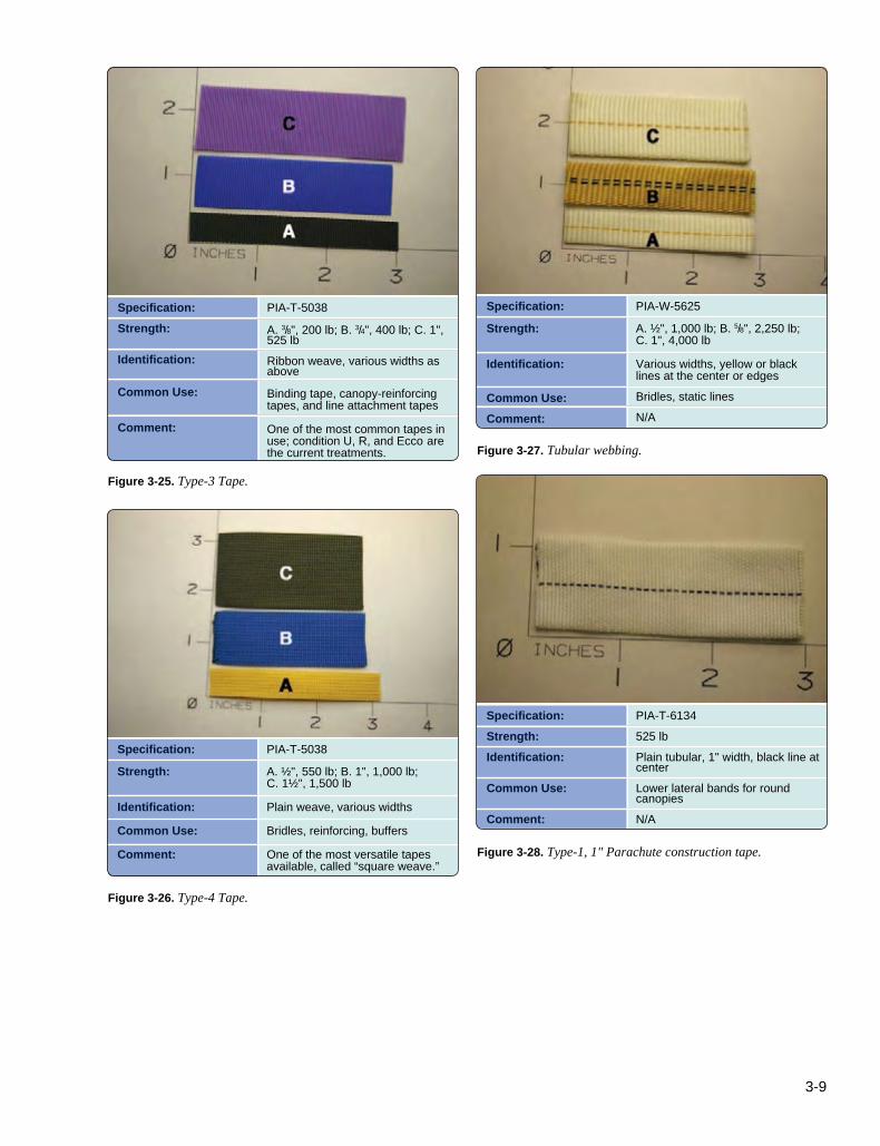
3-9
Specification:Strength:
Identification:
Common Use:
Comment:
PIA-T-5038
A. 3/8", 200 lb; B. 3/4", 400 lb; C. 1", 525 lbRibbon weave, various widths as above
Binding tape, canopy-reinforcing tapes, and line attachment tapes
One of the most common tapes in use; condition U, R, and Ecco are the current treatments.
Specification:
Strength:
Identification:
Common Use:Comment:
PIA-W-5625
A. ½", 1,000 lb; B. 5/8", 2,250 lb; C. 1", 4,000 lb
Various widths, yellow or black lines at the center or edgesBridles, static linesN/A
Specification:
Strength:
Identification:
Common Use:
Comment:
PIA-T-5038
A. ½", 550 lb; B. 1", 1,000 lb; C. 1½", 1,500 lb
Plain weave, various widths
Bridles, reinforcing, buffers
One of the most versatile tapes available, called “square weave.”
Specification:Strength:Identification:
Common Use:
Comment:
PIA-T-6134525 lbPlain tubular, 1" width, black line at centerLower lateral bands for round canopiesN/A
Figure 3-25. Type-3 Tape.
Figure 3-27. Tubular webbing.
Figure 3-26. Type-4 Tape.
Figure 3-28. Type-1, 1" Parachute construction tape.

3-10
Specification:Strength:Identification:Common Use:Comment:
Commercial, No. 16551,200 lbHerringbone weave, 2"Reserve free bag bridlesN/A
Specification:Strength:Identification:Common Use:
Comment:
PIA-T-87130A. 550 lb; B. 525 lb; C. 3,000 lbN/ATandem drogue bridles, canopy reinforcingA. Ty-1 Class 2; B. Ty-6 Class 2; C. Ty-9 Class 5.
Specification:Strength:Identification:
Common Use:Comment:
Commercial, No. 7282N/ABlack dotted line down center of tapeSlider reinforcingN/A
Specification:Strength:Identification:Common Use:
Comment:
PIA-W-5664N/AA. 1½"; B. 1"Harness keepers and ripcord pocketsN/A
Figure 3-29. Tape, polyester, 2".
Figure 3-31. Kevlar® tape.
Figure 3-30. Tape, nylon, 3".
Figure 3-32. Cotton elastic webbing.

3-11
Specification:Strength:Identification:Common Use:
Comment:
PIA-C-5040A. 400 lb; B. 550 lbSheath and core constructionTy-2 used on T-10 canopies; Ty-3 used on 24" and 28" canopies A. Ty-2; B. Ty-3
Specification:Strength:Identification:Common Use:
Comment:
PIA-C-5040225 lbBraided lineUsed for the locking loop on risers and main closing loopsGenerally white with a dashed green tracer thread, but can be other colors
Specification:Strength:Identification:Common Use:Comment:
PIA-C-7515400 lbBraided lineSeveral sport round reservesN/A
Specification:Strength:
Identification:Common Use:
Comment:
PIA-C-50401,100 lb with core and 500 lbs without coreBraided lineUsed for main closing loops with core removedWhite, plain
Figure 3-33. Cord, nylon, Type-2 and Ty-3.
Figure 3-35. Cord, nylon, Type-2a.
Figure 3-34. Cord, nylon, Type-1a.
Figure 3-36. Cord, Nylon, Type-5.

3-12
Specification:Strength:
Identification:Common Use:Comment:
CommercialA. 400 lb; B. 500 lb; C. 600 lb; D. 900 lbBraided hollow lineRam-air canopiesN/A
Specification:Strength:Identification:Common Use:Comment:
Commercial300 lbBraided, untreatedCYPRES® closing loopsN/A
Specification:Strength:Identification:Common Use:Comment:
PIA-C-87129700 lbBraided, untreatedEarly ram-air canopiesN/A
Specification:Strength:Identification:Common Use:Comment:
CommercialA. 725 lb; B. 940 lb; C. 1,800 lbBraided lineModern ram-air canopiesN/A
Figure 3-37. Cord, Dacron.Figure 3-39. Cord, Spectra®.
Figure 3-38. Cord, Kevlar®. Figure 3-40. Cord, Spectra®.
HardwareHardware, as defined in the context of parachutes, is “all metal parts associated with parachutes, their systems, and their suspended loads.” Most riggers identify hardware as the snaps, adapters, rings, links, and releases commonly used on harnesses. In addition to these components, other hardware includes items such as lightweight links and snaps, ripcords and handles, stiffeners, grommets, springs, and snap fasteners. [Figures 3-44 through 3-79]
Most load bearing hardware consists of drop-forged alloy steel, sheet alloy steel, or forged aluminum alloy. Lightweight hardware may be stamped from the sheet alloy steel, or in rare instances, cast. Ripcord pins are cold forged. The majority of the load bearing hardware is forged carbon steel with either cadmium or zinc plating.

3-13
Specification:Strength:Identification:Common Use:Comment:
CommercialA. 1,000 lb; B. 1,600 lbBraidedStrong tandem main canopiesN/A
Specification:Strength:Identification:Common Use:Comment:
MIL-C-5650N/A1/8" diameterSafety stows on free bag systems Commonly known as “shockcord.”
Specification:Strength:Identification:Common Use:Comment:
CommercialA.500 lb; B. 700 lb; C. 1,000 lbBraidedModern ram-air canopies Low bulk, dimensionally stable but wears more rapidly than Spectra or Dacron lines
Specification:Strength:Identification:Common Use:
Comment:
V-T-29540 lbAs marked5 cord for general harness constructionComes waxed for hand tacking
Figure 3-41. Cord, Vectran® LCP. Figure 3-43. Cord, elastic.
Figure 3-42. Cord, HMA.
Figure 3-44. Cord, nylon, 5 cord Belbob.
In recent years, there has been a movement to produce newer design hardware of stainless steel. This removes the problem of plating and the environmental problems associated with it. However, stainless is harder on the forging dies and the finishing processes take longer. Consequently, stainless hardware is generally more expensive than carbon steel.
All specification hardware has the appropriate number stamped or marked on it. The MS prefix is on those with the MIL-SPEC certification. All with the newer PIA certification have the mark with the PS (Parachute Standards) prefix. [Figure 3-64] Most of the current hardware has the mark with the MS prefix. As current stocks deplete, the mark on new production is with the PS prefix.

3-14
Specification:Strength:
Identification:
Common Use:
Comment:
V-T-295A. E/8.5 lb; B. FF/16 lb; C. 3 cord/24 lb; D. 5 cord/40 lbAs marked
E thread for canopy and general sewing FF for container reinforcing 3 cord for light harness construction; 5 cord for general harness construction
These are the most common threads used.
Specification:Strength:Identification:Common Use:Comment:
MIL-T-4343580-90 lbBlack or white colorsHand tackingN/A
Specification:Strength:Identification:Common Use:
Comment:
V-T-276A. 4.5 lb; B. 16 lbN/A24/4 sealing reserves, 3-cord-hand tacking, break tackingsN/A
Specification:Proof Load:Identification:
Common Use:
Comment:
MS220442500 lbAs marked
Leg snaps on sport harnesses, USAF B-12 assembly
Used with small frame adjustable “V” ring.
Figure 3-45. Thread, nylon.
Figure 3-47. Thread, nylon, flat braided (supertack).
Figure 3-46. A. Thread, cotton, 24/4; B. Thread, cotton, 3-cord.
Figure 3-48. Snap, B-12.
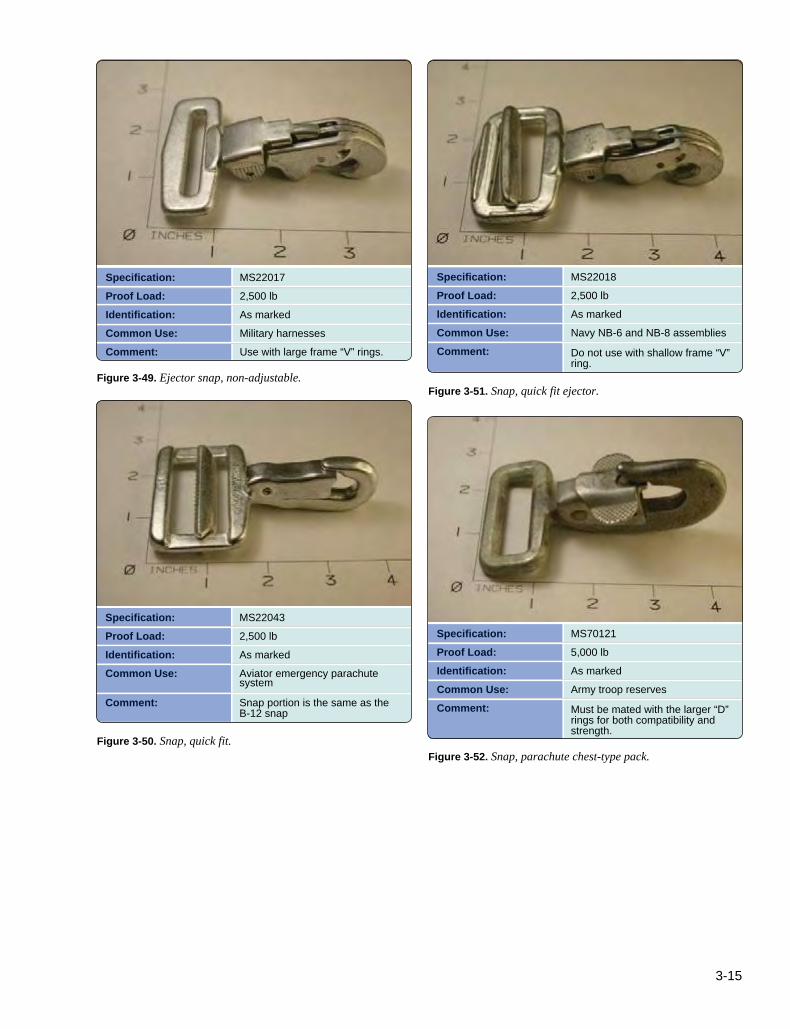
3-15
Specification:Proof Load:Identification:Common Use:Comment:
MS220172,500 lbAs markedMilitary harnessesUse with large frame “V” rings.
Specification:Proof Load:Identification:Common Use:Comment:
MS220182,500 lbAs markedNavy NB-6 and NB-8 assemblies
Do not use with shallow frame “V” ring.
Specification:Proof Load:Identification:Common Use:
Comment:
MS220432,500 lbAs markedAviator emergency parachute system
Snap portion is the same as the B-12 snap
Specification:Proof Load:Identification:Common Use:Comment:
MS701215,000 lbAs markedArmy troop reserves
Must be mated with the larger “D” rings for both compatibility and strength.
Figure 3-49. Ejector snap, non-adjustable.Figure 3-51. Snap, quick fit ejector.
Figure 3-50. Snap, quick fit.Figure 3-52. Snap, parachute chest-type pack.
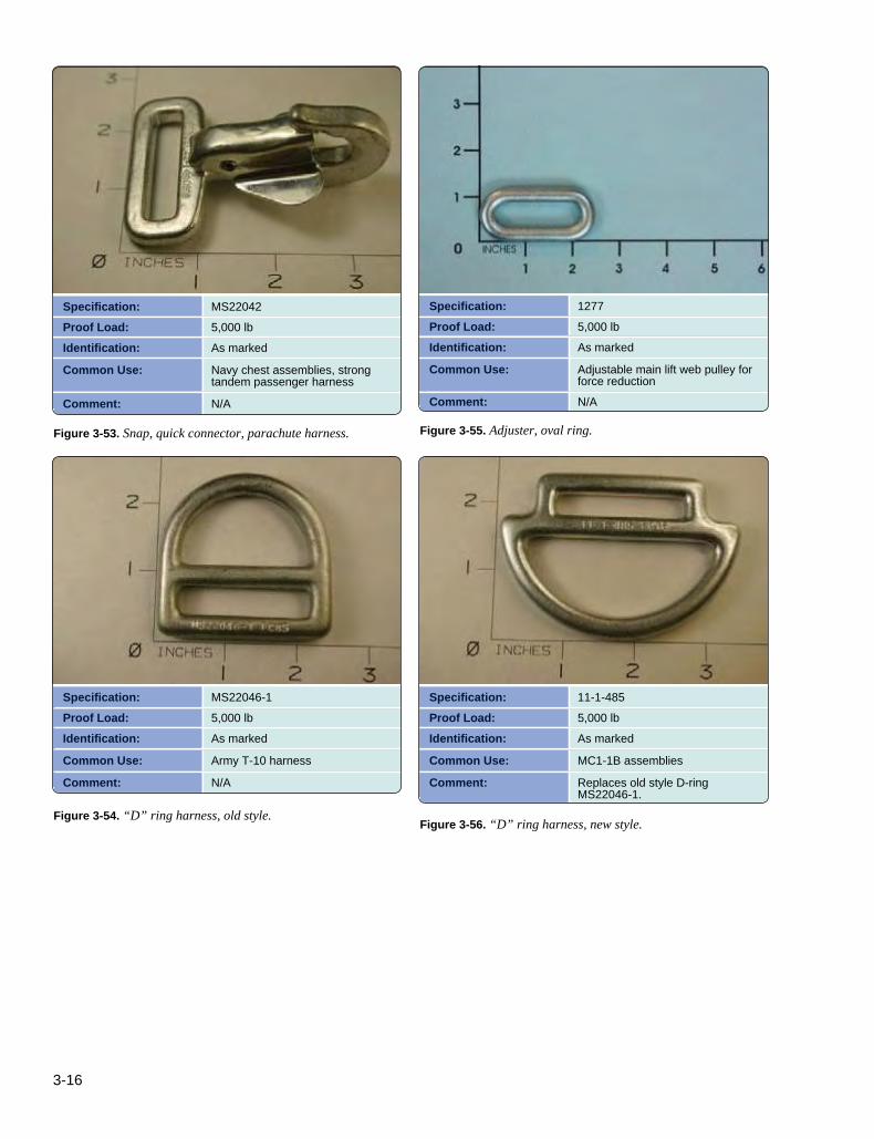
3-16
Specification:Proof Load:Identification:
Common Use:
Comment:
MS220425,000 lbAs marked
Navy chest assemblies, strong tandem passenger harness
N/A
Specification:Proof Load:Identification:
Common Use:
Comment:
12775,000 lbAs marked
Adjustable main lift web pulley for force reductionN/A
Specification:Proof Load:Identification:
Common Use:
Comment:
MS22046-15,000 lbAs marked
Army T-10 harness
N/A
Specification:Proof Load:Identification:
Common Use:
Comment:
11-1-4855,000 lbAs marked
MC1-1B assemblies
Replaces old style D-ring MS22046-1.
Figure 3-53. Snap, quick connector, parachute harness. Figure 3-55. Adjuster, oval ring.
Figure 3-54. “D” ring harness, old style.Figure 3-56. “D” ring harness, new style.

3-17
Specification:Proof Load:Identification:Common Use:Comment:
MS701132,500 lbAs markedB4 harnessesDo not use with quick ejector snaps
Specification:Proof Load:Identification:Common Use:
Comment:
MS701142,500 lbAs markedMilitary harnesses, sport harnessesN/A
Specification:Proof Load:Identification:Common Use:Comment:
MS277652,500 lbAs markedUsed with ejector snapsN/A
Specification:Proof Load:Identification:Common Use:
Comment:
MS220402,500 lbAs markedMilitary harnesses, sport harness thread-thru leg strap configurationN/A
Figure 3-57. “V” ring, quick fit, shallow frame. Figure 3-59. Adapter, quick fit, small frame.
Figure 3-58. “V” ring, quick fit, large frame.Figure 3-60. Adapter, quick fit, large frame.
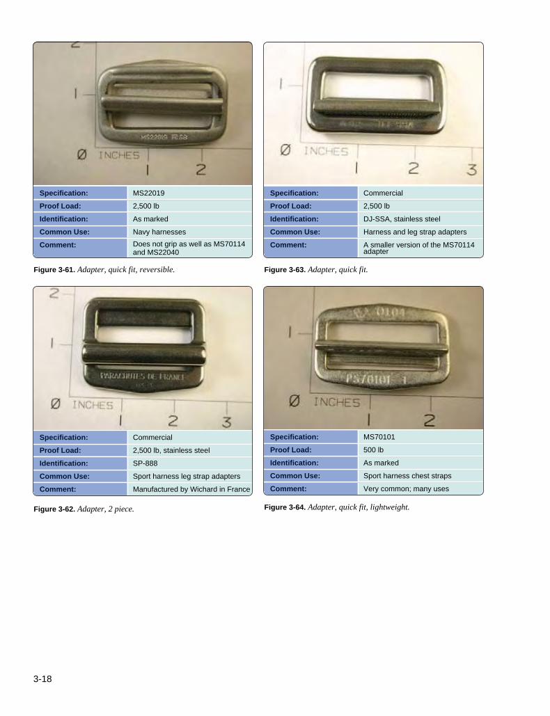
3-18
Specification:Proof Load:Identification:Common Use:Comment:
MS220192,500 lbAs markedNavy harnessesDoes not grip as well as MS70114 and MS22040
Specification:Proof Load:Identification:Common Use:Comment:
Commercial2,500 lbDJ-SSA, stainless steelHarness and leg strap adaptersA smaller version of the MS70114 adapter
Specification:Proof Load:Identification:Common Use:Comment:
Commercial2,500 lb, stainless steelSP-888Sport harness leg strap adaptersManufactured by Wichard in France
Specification:Proof Load:Identification:Common Use:Comment:
MS70101500 lbAs markedSport harness chest strapsVery common; many uses
Figure 3-61. Adapter, quick fit, reversible. Figure 3-63. Adapter, quick fit.
Figure 3-62. Adapter, 2 piece. Figure 3-64. Adapter, quick fit, lightweight.
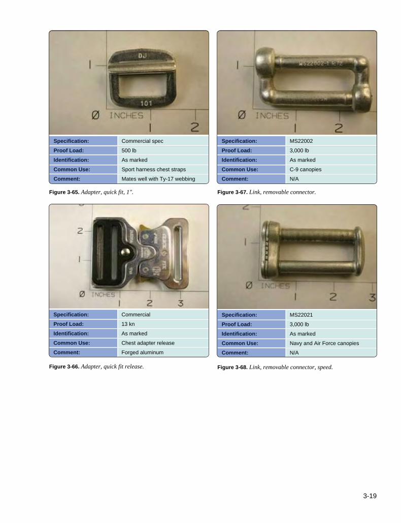
3-19
Specification:Proof Load:Identification:Common Use:Comment:
Commercial spec500 lbAs markedSport harness chest strapsMates well with Ty-17 webbing
Specification:Proof Load:Identification:Common Use:Comment:
MS220023,000 lbAs markedC-9 canopiesN/A
Specification:Proof Load:Identification:Common Use:Comment:
Commercial13 knAs markedChest adapter releaseForged aluminum
Specification:Proof Load:Identification:Common Use:Comment:
MS220213,000 lbAs markedNavy and Air Force canopiesN/A
Figure 3-65. Adapter, quick fit, 1". Figure 3-67. Link, removable connector.
Figure 3-66. Adapter, quick fit release. Figure 3-68. Link, removable connector, speed.

3-20
Specification:Proof Load/SWL:Identification:Common Use:
Comment:
CommercialAs marked on the link“Mallion Rapide®” markingsRam-air canopies, modern round reservesA. No. 6; B. No. 5; C. No. 4; D. No. 3.5
Specification:Proof Load:Identification:Common Use:Comment:
Commercial2,500 lbRW-1, 4453-ring release systemsNo. 445 shown
Specification:Proof Load:Identification:Common Use:Comment:
60B4312 (assembly)5,000 lbAs markedMilitary harnessesA. 60B4313/female B. 60J4328/male
Specification:Proof Load:Identification:Common Use:Comment:
Commercial500 lbRW-23-ring release systemsBottom riser ring
Figure 3-69. Link, Rapide®.
Figure 3-71. Ring, harness, 3-ring.
Figure 3-70. Release, parachute canopy quick disconnect, Capewell.
Figure 3-72. Ring, riser, middle, 3-ring.
Plastics and SyntheticsThe term “plastic” used here is a generic term for synthetic materials. The use of these materials is primarily for stiffeners in containers. They replace the metal stiffeners used in military systems. High-density polyethylene (HDPE) was the first material used followed by Lexan®. Time has
proven that moly disulfide (MDS) filled nylon is superior to the other materials and has become the most commonly used stiffener material. Today, the use of Lexan® is primarily in clear windows in pin protector flaps. Stiffeners should have rounded edges to prevent wear points and to minimize the ability of lines to half hitch around them. [Figures 3-80 through 3-84]

3-21
Specification:Proof Load:Identification:Common Use:Comment:
Commercial250 lbRW-33-ring release systemsUpper riser ring
Specification:Proof Load:Identification:Common Use:
Comment:
Commercial5,000 lbN/ATandem harness assemblies
Manufactured by Parachutes de France and Strong Enterprises
Specification:Proof Load:Identification:Common Use:
Comment:
Commercial250 lbRW-43-ring release systems
Small ring of mini 3-ring systems, riser guide rings
Specification:Proof Load:Identification:Common Use:
Comment:
Commercial2,500 lbRW-6Replaceable 3-ring harness ring
Replaces soft RW-1/82 and 83 harness rings.
Figure 3-73. Ring, riser, small, 3-ring.Figure 3-75. Ring, harness, tandem.
Figure 3-74. Ring, riser, mini, 3-ring.Figure 3-76. Ring, harness, replaceable, 3-ring.
FastenersFasteners are various types of devices designed to hold parts or components together or allow them to be held open or closed. The most common designs are hook and loop fasteners (Velcro®), snaps, grommets, and slide fasteners (zippers).
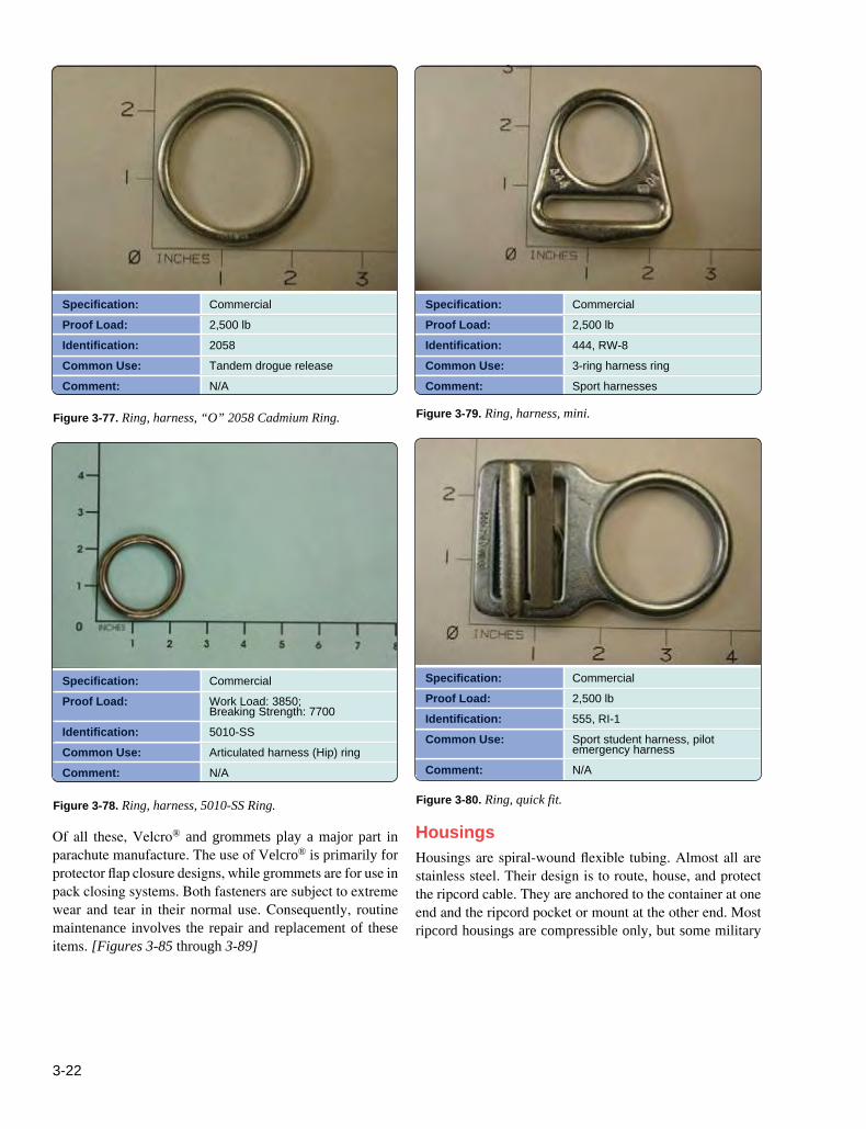
3-22
Specification:Proof Load:Identification:Common Use:Comment:
Commercial2,500 lb2058Tandem drogue releaseN/A
Specification:Proof Load:Identification:Common Use:Comment:
Commercial2,500 lb444, RW-83-ring harness ringSport harnesses
Specification:Proof Load:
Identification:Common Use:Comment:
CommercialWork Load: 3850; Breaking Strength: 77005010-SSArticulated harness (Hip) ringN/A
Specification:Proof Load:Identification:Common Use:
Comment:
Commercial2,500 lb555, RI-1Sport student harness, pilot emergency harnessN/A
Figure 3-77. Ring, harness, “O” 2058 Cadmium Ring. Figure 3-79. Ring, harness, mini.
Figure 3-78. Ring, harness, 5010-SS Ring. Figure 3-80. Ring, quick fit.
Of all these, Velcro® and grommets play a major part in parachute manufacture. The use of Velcro® is primarily for protector flap closure designs, while grommets are for use in pack closing systems. Both fasteners are subject to extreme wear and tear in their normal use. Consequently, routine maintenance involves the repair and replacement of these items. [Figures 3-85 through 3-89]
HousingsHousings are spiral-wound flexible tubing. Almost all are stainless steel. Their design is to route, house, and protect the ripcord cable. They are anchored to the container at one end and the ripcord pocket or mount at the other end. Most ripcord housings are compressible only, but some military

3-23
Specification:Proof Load:
Identification:Common Use:Comment:
CommercialA. Bronze, 800 lb; B. Stainless steel, 1,765 lbAs markedRSL lanyard releaseMade in bronze and stainless steel
Specification:Proof Load:Identification:Common Use:Comment:
11-1-6991-11,750 lbAs markedMilitary static linesN/A
Specification:Proof Load:Identification:Common Use:Comment:
MS-701201,750 lbAs markedMilitary and sport static linesN/A
Specification:Strength:Identification:Common Use:
Comment:
N/AN/AAs markedReplacement for Rapide® links on main and reserve canopiesN/A
Figure 3-81. Snap shackle.Figure 3-83. Snap, static line, new style.
Figure 3-82. Snap, static line, old style.Figure 3-84. Soft link.
housings used with seat parachutes are expandable as well. The reason that ripcord housings are compressible and non-expandable is to prevent premature loading of the cable and pin as the rig is donned and the user moves around. One-pin sport container systems generally use a .26" inside diameter housing. Two-pin and most military containers use a .375" inside diameter housing. Ripcord housings are measured under slight tension.
The 3-ring release system employs the smaller .20" or .18" housing for use with Lolon (yellow), or Teflon (orange or red), coated release cables. These “cutaway” housings must be expandable and non-compressible. The reason for this is, in the case where the loop load is excessive, the non-compressible housing will resist the loop or “push” against it allowing an effective “pull” of the cable from the loop.

3-24
Specification:Strength:Identification:Common Use:Comment:
CommercialN/A025", .040", .060"Stiffeners in container systemsThe preferred material in modern container systems.
Specification:Strength:Identification:Common Use:
Comment:
CommercialN/AOrange colorHand deploy handles, pinless student ripcordsN/A
Specification:Strength:Identification:Common Use:Comment:
CommercialN/A.040", .060"Stiffeners in container systemsUsed in older systems. Deforms easily.
Specification:Strength:Identification:Common Use:
Comment:
CommercialN/A.030", .060"Windows in container systems, stiffeners in older systemsBreaks easily
Figure 3-85. Molydisulfide Nylon—MDS (Nylatron®). Figure 3-87. HDPE tubing, 1 ½".
Figure 3-86. Poylethylene, high density (HDPE). Figure 3-88. Polycarbonate—Lexan®.
Thus the term “push-pull system.” A compressible housing compresses until it reaches its limit of compression, which could be as much as 20 percent of the total length. In a two-cable scenario, such as the 3-ring, the differential could be as much as to allow the short side to release without releasing the long side. Cutaway housings should be measured in a relaxed state and then compressed to ensure that it remains within the manufacturer’s allowable tolerance. [Figures 3-90A through 3-92C]
Ripcords, Cables, and SwagesThe standard ripcord used today on most parachute systems consists of a stainless steel handle, 3⁄32" 7 × 7 corrosion resistant steel cable, a stainless steel terminal ball, and one or more stainless steel pins swaged onto the cable. The handles come in various shapes and sizes in order to be compatible with main lift web lengths and pocket sizes and particulars, such as whether the ripcord grip is inboard or outboard. The terminal ball may be of several configurations, such as a