Dynamical Stability of the Intracluster Medium: Buoyancy Instabilities and Nanoastrophysics

CHAPTER 2
BUOYANCY, STABILITY AND SUBDIVISION
PART A - GENERAL Stockholm Agreement Ro-ro passenger craft operating to or from designated ports in North-West Europe and the Baltic Sea are subject to this regional agreement, details of which are given in:
The Stockholm Agreement (Agreement Concerning Specific Stability Requirements for RoRo Passenger Ships undertaking Regular Scheduled International Voyages Between or To or From Designated Ports in North West Europe and the Baltic Sea) 28 February 1996, the text of which is given as part of MSN 1790 (M) as amended, and which is invoked by:
SI 2004 No. 2884, the Merchant Shipping (Ro-Ro Passenger Ships) (Stability) Regulations 2004
The requirements include consideration of the effect on stability of water on deck after sustaining side damage. Guidance Notes on the application of The Stockholm Agreement to High-Speed Craft and of Annexes 1, 2 and 3 of the Agreement are given in Appendix C to these Instructions.
Reference should also be made to:
SI 2001 No. 152 The Merchant Shipping (Mandatory Surveys for Ro-Ro Ferry and High Speed Passenger Craft) Regulations 2001 as amended by SI 2004 No. 1266.
MGN 171 (M) Mandatory Surveys for Ro-Ro and High Speed Passenger Craft 2.1 General 2.1.1 A craft shall be provided with:
.1 stability characteristics and stabilization systems adequate for safety when the craft is operated in the non-displacement mode and during the transitional mode;
.2 buoyancy and stability characteristics adequate for safety where the craft is
operated in the displacement mode, both in the intact condition and the damaged condition; and
.3 stability characteristics in the non-displacement and transitional modes
adequate to transfer the craft safely to displacement mode in case of any system malfunction.
2.1.2 Account shall be taken of the effect of icing in the stability calculations. An example of established practice for ice accretion allowances is given in annex 5 for the guidance of the Administration. 2.1.3 For the purpose of this and other chapters, unless expressly defined otherwise, the following definitions apply:
MSIS034/ CHAPTER 2/ REV 1.01/ PAGE 1 OF 28

.1 "Downflooding point" means any opening, irrespective of size, that would permit passage of water through a water/weathertight structure (e.g., opening windows), but excludes any opening kept closed to an appropriate standard of water/weathertightness at all times other than when required for access or for operation of portable submersible bilge pumps in an emergency (e.g., non-opening windows of similar strength and weathertight integrity to the structure in which they are installed).
.2 “Elsewhere” when applied to sill and coaming heights in 2.2.7 and 2.2.8 is
taken as applying to all weathertight and watertight closures located on or below the datum.
.3 "Fully submerged foil" means a foil having no lift components piercing the
surface of the water in the foil-borne mode.
.4 "Monohull craft" means any craft which is not a multihull craft.
.5 "Multihull craft" means a craft which in any normally achievable operating trim or heel angle, has a rigid hull structure which penetrates the surface of the sea over more than one discrete area.
.6 "Permeability" of a space means the percentage of the volume of that space
which can be occupied by water.
.7 "Skirt" means a downwardly extending, flexible structure used to contain or divide an air cushion.
2.1.4 Other means of demonstrating compliance with the requirements of any part of this chapter may be accepted, provided that the method chosen can be shown to provide an equivalent level of safety. Such methods may include:
.1 mathematical simulation of dynamic behaviour; .2 scale model testing; and
.3 full-scale trials.
Before any reliance is placed upon mathematical simulations reference should be made to MCA Headquarters (Vessel Policy Unit) in every such case. 2.1.5 The adequacy of mathematical simulations must first be demonstrated by correlation with full-scale or model tests for the appropriate type of craft. It may be appropriate to use mathematical simulations to help to identify the more critical scenarios for subsequent physical testing.*
* Some mathematical simulation methods are not well suited to accurate modelling of extreme events. For safety level 3 or 4, it may be appropriate to use model testing as a precursor to, or instead of, full-scale testing. 2.1.6 Model or full-scale tests and/or calculations (as appropriate) shall also include consideration of the following known stability hazards to which high-speed craft are known to be liable, according to craft type:
.1 directional instability, which is often coupled with roll and pitch instabilities;
MSIS034/ CHAPTER 2/ REV 1.01/ PAGE 2

.2 broaching and bow diving in following seas at speeds near to wave speed, applicable to most types;
.3 bow diving of planing monohulls and catamarans due to dynamic loss of
longitudinal stability in relatively calm seas; .4 reduction in transverse stability with increasing speed of monohulls;
.5 porpoising of planing monohulls, being coupled pitch and heave oscillations,
which can become violent;
.6 chine tripping, being a phenomenon of planing monohulls occurring when the immersion of a chine generates a strong capsizing moment;
.7 plough-in of air-cushion vehicles, either longitudinal or transverse, as a result
of bow or side skirt tuck-under or sudden collapse of skirt geometry, which, in extreme cases, can result in capsize;
.8 pitch instability of SWATH (small waterplane area twin hull) craft due to the
hydrodynamic moment developed as a result of the water flow over the submerged lower hulls;
.9 reduction in effective metacentric height (roll stiffness) of surface effect ships
(SES) in high speed turns compared to that on a straight course, which can result in sudden increases in heel angle and/or coupled roll and pitch oscillations; and
.10 resonant rolling of SES in beam seas, which, in extreme cases, can result in
capsize. Further information about these known hazards may be found in the technical literature. Initially, the following may be found helpful, although the list is far from exhaustive:
.1 ‘A Case Study of Dynamic Instability in a Planing Hull’, Marine Technology, April 1987
.1-.3, .6 ‘Dynamic Stability of Planing Boats’, trans SNAME, Miami, February 1991
.2 & .3 ‘Test Techniques and Prediction Methods for Assessment of High-Speed Dynamic Stability’, FAST’95
.2 & .3 MGN 327(M) and MGN 328(M)
.4 ‘Transverse Stability of Round-Bottomed High Speed Craft Underway’, National Physical Laboratory Report 98, October 1968
.4 ‘Transverse Dynamic Stability of Planing Craft’, Marine Technology, Vol. 34, No. 2, April 1997
.5 ‘Theoretical Determination of Porpoising Instability of High-Speed Planing Boats’, Journal of Ship Research, Vol. 22, No. 1, March 1978
.7 ‘Report of the ARB Special Committee on Hovercraft Stability and Control’, CAA Paper 75017, Civil Aviation Authority, London, June 1975
.8 ‘The HSVA Systematic SWATH Model Series’, FAST '95.
.9 & .10 ‘Means of Compliance – Stability of Sidewall Craft in the On-Cushion Mode’, Technical Note 92001, CAA Hovercraft Dept, January 1992
MSIS034/ CHAPTER 2/ REV 1.01/ PAGE 3

2.1.7 Suitable calculations shall be carried out and/or tests conducted to demonstrate that, when operating within approved operational limitations, the craft will, after a disturbance causing roll, pitch, heave or heel due to turning or any combination thereof, return to the original attitude. Where calculations are employed, it shall first be shown that they correctly represent dynamic behaviour within the operational limitations of the craft. Model tests and full-scale trials are strongly preferred to satisfy this requirement. 2.2 Intact buoyancy and watertight and weathertight integrity The term “datum” is defined in 1.4.20, and the term “design waterline” in 1.4.21. The term “ro-ro craft” is defined in 1.4.51, the term “ro-ro space” in 1.4.52, and the term “special category space” in 1.4.55. The term “watertight” is defined in 1.4.58, and the term “weathertight” in 1.4.60. 2.2.1 Buoyant spaces* * These requirements encompass the need for all shell apertures and their closures to be provided with satisfactory integrity. 2.2.1.1 All craft shall have a sufficient reserve of buoyancy at the design waterline to meet the intact and damage stability requirements of this chapter. The Administration may require a larger reserve of buoyancy to permit the craft to operate in any of its intended modes. This reserve of buoyancy shall be calculated by including only those compartments that are: .1 watertight and situated below the datum, or
.2 watertight or weathertight and situated above the datum.
In considering the stability after damage, flooding shall be assumed to occur until limited by watertight boundaries in the equilibrium condition, and weathertight boundaries in intermediate stages of flooding and within the range of positive righting lever required to satisfy the residual stability requirements. Where a buoyant space may be subjected to increased fluid pressure in the equilibrium position after damage, the boundaries and associated openings and penetrations of that space shall be designed and constructed to prevent the passage of fluid under that pressure. Craft built in conformity with the requirements of organizations recognised by the Administration, in accordance with regulation XI/1 of the Convention, may be considered to possess adequate strength and integrity. 2.2.1.2 Arrangements shall be provided for checking the watertight or weathertight integrity of those compartments taken into account in 2.2.1.1, and the details incorporated in the craft operating manual required by 18.2.1. 2.2.2 Openings in watertight divisions 2.2.2.1 The number of openings in watertight bulkheads shall be reduced to the minimum compatible with the design and proper working of the craft, and all such doors shall be closed prior to departure of the craft from the berth.
MSIS034/ CHAPTER 2/ REV 1.01/ PAGE 4

2.2.2.2 Doors in watertight bulkheads may be hinged or sliding. They shall be shown by suitable testing to be capable of maintaining the watertight integrity of the bulkhead. Such testing shall be carried out for both sides of the door and shall apply a pressure head 10% greater than that determined from the minimum permissible height of a downflooding opening. Testing may be carried out either before or after the door is fitted into the craft but, where shore testing is adopted, satisfactory installation in the craft shall be verified by inspection and hose testing. 2.2.2.3 Type approval may be accepted in lieu of testing individual doors, provided the approval process includes pressure testing to a head equal to, or greater, than the required head (refer to 2.2.2.2). 2.2.2.4 All watertight doors shall be capable of being operated when the craft is inclined up to 15°, and shall be fitted with means of indication in the operating compartment showing whether they are open or closed. All such doors shall be capable of being opened and closed locally from each side of the bulkhead. 2.2.2.5 Watertight doors shall remain closed when the craft is at sea, except that they may be opened for access. A notice shall be attached to each door to the effect that it is not to be left open. 2.2.2.6 Watertight doors shall be capable of being closed by remote control from the operating compartment in not less than 20 s and not more than 40 s, and shall be provided with an audible alarm, distinct from other alarms in the area, which will sound for at least 5 s but no more than 10 s before the doors begin to move whenever the door is closed remotely by power, and continue sounding until the door is completely closed. The power, control and indicators shall be operable in the event of main power failure, as required by regulation II-1/15.7.3 of the Convention. In passenger areas and areas where the ambient noise exceeds 85 dB(A) the audible alarm shall be supplemented by an intermittent visual signal at the door. If the Administration is satisfied that such doors are essential for the safe work of the craft, hinged watertight doors having only local control may be permitted for areas to which crew only have access, provided they are fitted with remote indicators as required by 2.2.2.4. 2.2.2.7 Where pipes, scuppers, electric cables, etc. are carried through watertight divisions, the arrangements for creating a watertight penetration shall be of a type which has been prototype tested under hydrostatic pressure equal to or greater than that required to be withstood for the actual location in the craft in which they are to be installed. The test pressure shall be maintained for at least 30 min and there must be no leakage through the penetration arrangement during this period. The test pressure head shall be 10% greater than that determined from the minimum permissible height of a downflooding opening. Watertight bulkhead penetrations which are effected by continuous welding do not require prototype testing. Valves on scuppers from weathertight compartments, included in the stability calculations, shall have arrangements for remote closing from the operating station. 2.2.2.8 Where a ventilation trunk forms part of a watertight boundary, the trunk shall be capable of withstanding the water pressure that may be present taking into account the maximum inclination angle allowable during all stages of flooding. 2.2.3 Inner bow doors
MSIS034/ CHAPTER 2/ REV 1.01/ PAGE 5

2.2.3.1 Where ro-ro craft are fitted with bow loading openings, an inner bow door shall be fitted abaft such openings, to restrict the extent of flooding in the event of failure of the outer closure. This inner bow door, where fitted, shall be:
.1 weathertight to the deck above, which deck shall itself be weathertight forward to the bow loading opening;
.2 so arranged as to preclude the possibility of a bow loading door causing
damage to it in the case of damage to, or detachment of, the bow loading door;
.3 forward of all positions on the vehicle deck in which vehicles are intended to
be carried; and
.4 part of a boundary designed to prevent flooding into the remainder of the craft.
It should be noted that unlike conventional ships, there is no requirement as such for a collision bulkhead to be fitted to HSC Code craft. 2.2.3.2 A craft may be exempted from the requirement for such an inner bow door where one of the following applies:
.1 the vehicle loading deck at the inner bow door position is above the design waterline by a height more than the significant wave height corresponding to the worst intended conditions;
.2 it can be demonstrated using model tests* or mathematical simulations that
when the craft is proceeding at a range of speeds up to the maximum attainable speed in the loaded condition at all headings in long crested seas of the greatest significant wave height corresponding to the worst intended conditions, either:
* Reference should be made to MSC/Circ.1195 (Guidelines for the Conduct of High Speed Craft Model Tests) which provides guidelines for the conduct of high-speed craft model testing.
.1 the bow loading door is not reached by waves; or
.2 having been tested with the bow loading door open to determine the
maximum steady state volume of water which accumulates, it can be shown by static analysis that, with the same volume of water on the vehicle deck(s) the residual stability requirements of 2.6.11 and 2.13 or 2.15 are satisfied. If the model tests or mathematical simulations are unable to show that the volume of water accumulated reaches a steady state, the craft shall be considered not to have satisfied the conditions of this exemption.
Where mathematical simulations are employed they shall already have been verified against full-scale or model testing;
The term “worst intended conditions” is defined in 1.4.61.
.3 bow loading openings lead to open ro-ro spaces provided with guard-rails or
having freeing ports complying with 2.2.3.2.4; MSIS034/ CHAPTER 2/ REV 1.01/ PAGE 6

.4 the deck of the lowest ro-ro space above the design waterline is fitted on
each side of the deck with freeing ports evenly distributed along the sides of the compartment. These shall either be proven to be acceptable using tests according to 2.2.3.2.2 above or comply with the following:
.1 A > 0.3 l
where :
A = the total area of freeing ports on each side of the deck
in m2; and
l = the length of the compartment in m;
.2 the craft shall maintain a residual freeboard to the deck of the ro-ro space of at least 1 m in the worst condition;
.3 such freeing ports shall be located within the height of 0.6 m above
the deck of the ro-ro space, and the lower edge of the ports shall be within 0.02 m above the deck of the ro-ro space; and
.4 such freeing ports shall be fitted with closing devices or flaps to
prevent water entering the deck of the ro-ro space whilst allowing water which may accumulate on the deck of the ro-ro space to drain.
2.2.4 Other provisions for ro-ro craft The term “ro-ro craft” is defined in 1.4.51, “ro-ro space” in 1.4.52, and “special category space” in 1.4.55. 2.2.4.1 All accesses in the ro-ro space that lead to spaces below the deck shall have a lowest point which is not less than the height required from the tests conducted according to 2.2.3.2.2 or 3 m above the design waterline. 2.2.4.2 Where vehicle ramps are installed to give access to spaces below the deck of the ro-ro space, their openings shall be capable of being closed weathertight to prevent ingress of water below. 2.2.4.3 Accesses in the ro-ro space that lead to spaces below the ro-ro deck and having a lowest point which is less than the height required from the tests conducted according to 2.2.3.2.2 or 3 m above the design waterline may be permitted provided they are watertight and are closed before the craft leaves the berth on any voyage and remain closed until the craft is at its next berth. 2.2.4.4 The accesses referred to in 2.2.4.2 and 2.2.4.3 above shall be fitted with alarm indicators in the operating compartment. 2.2.4.5 Special category spaces and ro-ro spaces shall be patrolled or monitored by effective means, such as television surveillance, so that any movement of vehicles in adverse weather conditions and unauthorized access by passengers thereto can be detected whilst the craft is underway (refer to 7.8.3.1).
MSIS034/ CHAPTER 2/ REV 1.01/ PAGE 7
2.2.5 Indicators and surveillance 2.2.5.1 Indicators Indicators shall be provided in the operating compartment for all shell doors, loading doors and other closing appliances which, if left open or not properly secured, could lead to major flooding in the intact and damage conditions. The indicator system shall be designed on the fail-safe principle and shall show by visual alarms if the door is not fully closed or if any of the securing arrangements are not in place and fully locked, and by audible alarms if such door or closing appliance becomes open or the securing arrangements become unsecured. The indicator panel in the operating compartment shall be equipped with a mode selection function 'harbour/sea voyage' so arranged that an audible alarm is given in the operating compartment if the craft leaves harbour with the bow doors, inner doors, stern ramp or any other side shell doors not closed or any closing device not in the correct position. The power supply for the indicator systems shall be independent of the power supply for operating and securing the doors. 2.2.5.2 Television surveillance Television surveillance and a water leakage detection system shall be arranged to provide an indication to the operating compartment and to the engine control station of any leakage through inner and outer bow doors, stern doors or any other shell doors which could lead to major flooding. The term “operating compartment” is defined in 1.4.43. For guidance on power supply of the television surveillance system refer to the guidance under 7.8.3.1. 2.2.6 Integrity of superstructure 2.2.6.1 Where entry of water into structures above the datum would significantly influence the stability and buoyancy of the craft, such structures shall be:
.1 of adequate strength to maintain the weathertight integrity and fitted with weathertight closing appliances; or
.2 provided with adequate drainage arrangements; or
.3 an equivalent combination of both measures.
2.2.6.2 Weathertight superstructures and deckhouses located above the datum shall in the outside boundaries have means of closing openings with sufficient strength such as to maintain weathertight integrity in all damage conditions where the space in question is not damaged. Furthermore, the means of closing shall be such as to maintain weathertight integrity in all operational conditions. 2.2.7 Doors, windows, etc., in boundaries of weathertight spaces 2.2.7.1 Doors, windows, etc., and any associated frames and mullions in weathertight superstructures and deckhouses shall be weathertight and shall not leak or fail at a uniformly applied pressure less than that at which adjacent structure would experience permanent set or fail. Conformity with the requirements of organizations recognized by the Administration
MSIS034/ CHAPTER 2/ REV 1.01/ PAGE 8

in accordance with regulation XI/1 of the Convention may be considered to possess adequate strength. 2.2.7.2 For doors in weathertight superstructures, hose tests shall be carried out with a water pressure from the outside in accordance with specifications at least equivalent to those acceptable to the Organization.* * Refer to ISO 6042 – Ships and Marine Technology – Weathertight single-leaf doors, or a similar standard. 2.2.7.3 The height above the deck of sills to doorways leading to exposed decks shall be as high above the deck as is reasonable and practicable, particularly those located in exposed positions. Such sill heights shall in general not be less than 100 mm for doors to weathertight spaces on decks above the datum, and 250 mm elsewhere*. For craft of 30 m in length and under, sill heights may be reduced to the maximum which is consistent with the safe working of the craft. * Refer to paragraph 2.1.3.2. 2.2.7.4 Windows shall not be permitted in the boundaries of special category spaces or ro-ro spaces or below the datum. If required by restrictions in the Permit to Operate, forward facing windows, or windows which may be submerged at any stage of flooding shall be fitted with hinged or sliding storm shutters ready for immediate use. 2.2.7.5 Sidescuttles to spaces below the datum shall be fitted with efficient hinged deadlights arranged inside so that they can be effectively closed and secured watertight. 2.2.7.6 No sidescuttle shall be fitted in a position so that its sill is below a line drawn parallel to and one metre above the design waterline. See also the Guidance Notes regarding windows given under Chapter 3 – Structure. 2.2.8 Hatchways and other openings 2.2.8.1 Hatchways closed by weathertight covers The construction and the means for securing the weathertightness of cargo and other hatchways shall comply with the following:
.1 coaming heights shall in general not be less than 100 mm for hatches to weathertight spaces on decks above the datum, and 250 mm elsewhere*. For craft of 30 m in length and under, coaming heights may be reduced to the maximum which is consistent with the safe working of the craft;
* Refer to paragraph 2.1.3.2.
.2 the height of these coamings may be reduced, or the coamings omitted entirely, on condition that the Administration is satisfied that the safety of the ship is not thereby impaired in any sea conditions up to the worst intended conditions. Where coamings are provided, they shall be of substantial construction; and
.3 the arrangements for securing and maintaining weathertightness shall ensure
that the tightness can be maintained in any sea conditions up to the worst intended conditions.
MSIS034/ CHAPTER 2/ REV 1.01/ PAGE 9

2.2.8.2 Machinery space openings 2.2.8.2.1 Machinery space openings shall be properly framed and efficiently enclosed by casings of ample strength and, where the casings are not protected by other structures, their strength shall be specially considered. Access openings in such casings shall be fitted with weathertight doors#. # Conformity with the requirements of organizations recognized by the Administration in accordance with regulation XI-1/1 of the Convention may be considered to possess adequate strength. 2.2.8.2.2 Heights of sills and coaming shall, in general, not be less than 100 mm for openings to weathertight spaces on decks above the datum, and 380 mm elsewhere*. For craft of 30 m in length and under, these heights may be reduced to the maximum which is consistent with the safe working of the craft. * Refer to paragraph 2.1.3.2. 2.2.8.2.3 Machinery space ventilator openings shall comply with the requirements of 2.2.8.4.2. 2.2.8.3 Miscellaneous openings in exposed decks 2.2.8.3.1 Manholes and flush scuttles on the datum or within superstructures other than enclosed superstructures shall be closed by substantial covers capable of being made watertight. Unless secured by closely spaced bolts, the covers shall be permanently attached. 2.2.8.3.2 Service hatches to machinery, etc. may be arranged as flush hatches provided that the covers are secured by closely spaced bolts, are kept closed at sea, and are equipped with arrangements for portable guardrails. 2.2.8.3.3 Openings in exposed decks leading to spaces below the datum or enclosed superstructures other than hatchways, machinery space openings, manholes and flush scuttles shall be protected by an enclosed superstructure, or by a deckhouse or companionway of equivalent strength and weathertightness. 2.2.8.3.4 The height above the deck of sills to the doorways in companionways shall, in general, not be less than 100 mm for doors to weathertight spaces on decks above the datum, and 250 mm elsewhere*. For craft of 30 m in length and under sill heights may be reduced to the maximum which is consistent with the safe working of the craft. * Refer to paragraph 2.1.3.2. 2.2.8.4 Ventilators 2.2.8.4.1 Ventilators to spaces below the datum or decks of enclosed superstructures shall have substantially constructed coamings efficiently connected to the deck. Coaming heights shall in general not be less than 100 mm for ventilators to weathertight spaces on decks above the datum, and 380 mm elsewhere*. For craft of 30 m in length and under, coaming heights may be reduced to the maximum which is consistent with the safe working of the craft. * Refer to paragraph 2.1.3.2.
MSIS034/ CHAPTER 2/ REV 1.01/ PAGE 10

2.2.8.4.2 Ventilators the coamings of which extend to more than one metre above the deck or which are fitted to decks above the datum need not be fitted with closing arrangements unless they face forward or are specifically required by the Administration. 2.2.8.4.3 Except as provided in 2.2.8.4.2, ventilator openings shall be provided with efficient weathertight closing appliances. 2.2.8.4.4 Ventilator openings shall face aft or athwartships wherever practicable. 2.2.9 Scuppers, inlets and discharges 2.2.9.1 Discharges led through the shell either from spaces below the datum or from within superstructures and deckhouses fitted above the datum shall be fitted with efficient and accessible means for preventing water from passing inboard. Normally each separate discharge shall have one automatic non-return valve with a positive means of closing it from a position above the datum. Where, however, the vertical distance from the design waterline to the inboard end of the discharge pipe exceeds 0.01 L, the discharge may have two automatic non-return valves without positive means of closing, provided that the inboard valve is always accessible for examination under service conditions. Where that vertical distance exceeds 0.02 L, a single automatic non-return valve without positive means of closing may be accepted. The means for operating the positive action valve shall be readily accessible and provided with an indicator showing whether the valve is open or closed. 2.2.9.2 Valves on scuppers from weathertight compartments included in the stability calculations shall be operable from the operating compartment. 2.2.9.3 In manned machinery spaces, main and auxiliary sea inlets and discharges in connection with the operation of machinery may be controlled locally. Such controls shall be readily accessible and shall be provided with indicators showing whether the valves are open or closed. In unmanned machinery spaces, main and auxiliary sea inlet and discharge controls in connection with the operation of machinery shall either:
.1 be located at least 50% of the significant wave height corresponding to the worst intended conditions above the deepest flooded waterline following damage specified in 2.6.6 to 2.6.10; or
.2 be operable from the operating compartment.
2.2.9.4 Scuppers leading from superstructures or deckhouses not fitted with weathertight doors shall be led overboard. 2.2.9.5 All shell fittings and the valves required by this Code shall be of a suitable ductile material. Valves of ordinary cast iron or similar material shall not be acceptable. 2.2.10 Air pipes 2.2.10.1 Main storage tanks containing flammable liquids or tanks which can be pumped or filled from the sea shall have air pipes which do not terminate in enclosed spaces. 2.2.10.2 All air pipes extending to exposed decks shall have a height from the deck to the point where water may have access below of at least 300 mm where the deck is less than 0.05L above the design waterline, and 150 mm on all other decks.
MSIS034/ CHAPTER 2/ REV 1.01/ PAGE 11

2.2.10.3 Air pipes may discharge through the side of the superstructure provided that this is at a height of at least 0.02L above any waterline when the intact craft is heeled to an angle of 15°, or 0.02L above the highest waterline at all stages of flooding as determined by the damaged stability calculations, whichever is higher. 2.2.10.4 All air pipes shall be equipped with weathertight closing devices that close automatically. 2.2.11 Freeing ports 2.2.11.1 Where bulwarks on weather decks form wells, ample provision shall be made for rapidly freeing the decks of water and for draining them. The minimum freeing port area (A) on each side of the craft for each well on the weather deck of the main hull(s) shall be:
.1 where the length of bulwark (l) in the well is 20 m or less: A = 0.7 + 0.035 l (m2); and
.2 where l exceeds 20 m: A = 0.07 l (m2),
and, in no case, l need be taken as greater than 0.7 L. If the bulwark is more than 1.2 m in average height, the required area shall be increased by 0.004 square metres per metre of length of well for each 0.1 m difference in height. If the bulwark is less than 0.9 m in average height, the required area shall be decreased by 0.004 square metres per metre of length of well for each 0.1 m difference in height. 2.2.11.2 Such freeing ports shall be located within the height of 0.6 m above the deck and the lower edge shall be within 0.02 m above the deck. 2.2.11.3 All such openings in the bulwarks shall be protected by rails or bars spaced approximately 230 mm apart. If shutters are fitted to freeing ports, ample clearance shall be provided to prevent jamming. Hinges shall have pins or bearings of non-corrodible material. If shutters are fitted with securing appliances, these appliances shall be of approved construction. 2.2.11.4 Craft having superstructures which are open in front or both ends shall comply with the provisions of 2.2.11.1. 2.2.11.5 In craft having superstructures which are open at the aft end the minimum freeing port area shall be:
A = 0.3 b (m2) where:
b = the breadth of the craft at the exposed deck (m). 2.2.11.6 Ro-ro craft fitted with bow loading openings leading to open vehicle spaces shall comply with the provisions of 2.2.3. 2.3 Intact stability in the displacement mode
MSIS034/ CHAPTER 2/ REV 1.01/ PAGE 12

The term “displacement mode” is defined in 1.4.22. The term “hydrofoil craft” is defined in 1.4.31, and the term “fully-submerged foil” in 2.1.3.2. Hydrofoil craft may be of monohull or multihull form. The term “monohull craft” is defined in 2.1.3.3, and “multihull craft” in 2.1.3.4. 2.3.1 Hydrofoil craft fitted with surface-piercing foils and/or fully submerged foils shall have sufficient stability under all permitted cases of loading to comply with the relevant provisions of annex 6 and specifically maintain a heel angle of less than 10º when subjected to the greater of the heeling moments in 1.1.2 and 1.1.4 of that annex. 2.3.2 Subject to 2.3.4, multihull craft other than hydrofoil craft shall meet the relevant requirements of annex 7 in all permitted cases of loading. 2.3.3 Subject to 2.3.4, monohull craft other than hydrofoil craft shall meet the relevant requirements of annex 8 in all permitted conditions of loading. 2.3.4 Where the characteristics of multihull craft are inappropriate for application of annex 7 or the characteristics of monohull craft are inappropriate for application of annex 8, the Administration may accept alternative criteria equivalent to those stipulated, as appropriate to the type of craft and area of operation. The requirements of annexes 7 and 8 may be applied as indicated in the table below.
Table 2.3.4 Application of annexes 7 and 8 to monohull and multihull craft*
Angle of maximum GZ GMT
≤ 25º > 25º
< 3.0 annex 7 or annex 8 annex 8
> 3.0 annex 7 annex 7 or annex 8 where:
GMT = transverse metacentric height in the loading condition corresponding to the design waterline, corrected for free surface effects (m)
GZ = righting lever
* Table 2.3.4 is advisory, and accommodates cases where a monohull has stability characteristics like a multihull, and those of a multihull that are like a monohull. Examples: multihull criteria may not prove suitable for all styles of trimaran; monohull criteria may not prove suitable for air cushion vehicles in the
displacement mode. 2.4 Intact stability in the non-displacement mode The term “non-displacement mode” is defined in 1.4.39 2.4.1 The requirements of this section and section 2.12 shall be applied on the assumption that any stabilisation systems fitted are fully operational.
MSIS034/ CHAPTER 2/ REV 1.01/ PAGE 13

2.4.2 The roll and pitch stability on the first and/or any other craft of a series shall be qualitatively assessed during operational safety trials as required by chapters 17 and 18 and annex 9. The results of such trials may indicate the need to impose operational limitations. 2.4.3 Where craft are fitted with surface-piercing structure or appendages, precautions shall be taken against dangerous attitudes or inclinations and loss of stability subsequent to a collision with a submerged or floating object. 2.4.4 In designs where periodic use of cushion deformation is employed as a means of assisting craft control, or periodic use of cushion air exhausting to atmosphere for purposes of craft manoeuvring, the effects upon cushion-borne stability shall be determined, and the limitations on the use by virtue of craft speed or attitude shall be established. 2.4.5 In the case of an air cushion vehicle fitted with flexible skirts, it shall be demonstrated that the skirts remain stable under operational conditions. The term “air-cushion vehicle” includes both amphibious and sidewall types (see 1.4.56) and is defined in 1.4.2. The term “skirt” is defined in 2.1.3.6. 2.5 Intact stability in the transitional mode The term “transitional mode” is defined in 1.4.57. 2.5.1 Under weather conditions up to the worst intended conditions, the time to pass from the displacement mode to the non-displacement mode and vice versa shall be minimized unless it is demonstrated that no substantial reduction of stability occurs during this transition. 2.5.2 Hydrofoil craft shall comply with the relevant provisions of annex 6. 2.6 Buoyancy and stability in the displacement mode following damage 2.6.1 The requirements of this section apply to all permitted conditions of loading. 2.6.2 For the purpose of making damage stability calculations, the volume and surface permeabilities shall be, in general, as follows:
Spaces Permeability
Appropriated to cargo or stores
Occupied by accommodation
Occupied by machinery
Intended for liquids
Appropriated for cargo vehicles
Void spaces
60
95
85
0 or 95*
90
95
* whichever results in the more severe requirements
MSIS034/ CHAPTER 2/ REV 1.01/ PAGE 14

2.6.3 Notwithstanding 2.6.2, permeability determined by direct calculation shall be used where a more onerous condition results, and may be used where a less onerous condition results from that provided according to 2.6.2. Note that some designs have stiffening external to the compartment itself, and thus the use of permeability greater than 0.95 may be appropriate where such spaces are void. 2.6.4 The Administration may permit the use of low-density foam or other media to provide buoyancy in void spaces, provided that satisfactory evidence is provided that any such proposed medium is the most suitable alternative and is:
.1 of closed-cell form if foam, or otherwise impervious to water absorption*;
* Reference may be made to, Cellular plastics, rigid — Determination of water absorption for assessing water absorption properties (ISO 2896:1987). The water absorption of low density material should not exceed 8 % by volume after being fully submerged for 8 days according to ISO 2896 should be considered to be “impervious to water absorption”. Material complying with IMO Resolution MSC.81(70) as amended by MSC.226(82) should also be deemed to satisfy this standard. Refer to:– Small craft – Stability and buoyancy (ISO 12217). The use of low density foam shall be discouraged on UK HSC.
.2 structurally stable under service conditions; .3 chemically inert in relation to structural materials with which it is in contact or
other substances with which the medium is likely to be in contact (reference is made to 7.4.3.7); and
.4 properly secured in place and easily removable for inspection of the void
spaces.
2.6.5 The Administration may permit void bottom spaces to be fitted within the watertight envelope of the hull without the provision of a bilge system or air pipes provided that:
.1 the structure is capable of withstanding the pressure head after any of the damages required by this section;
.2 when carrying out a damage stability calculation in accordance with the
requirements of this section, any void space adjacent to the damaged zone shall be included in the calculation and the criteria in 2.6, 2.13 and 2.15 complied with;
When calculating damage stability: any of those compartments adjacent to the damaged compartment should be included in the calculation.
.3 the means by which water which has leaked into the void space is to be removed shall be included in the craft operating manual required by chapter 18; and
.4 adequate ventilation is provided for inspection of the space under
consideration as required by 2.2.1.2. .5 void spaces filled with foam or modular buoyancy elements or any space
without a venting system are considered to be void spaces for the purposes
MSIS034/ CHAPTER 2/ REV 1.01/ PAGE 15
of this paragraph, provided such foam or elements fully comply with 2.6.4.
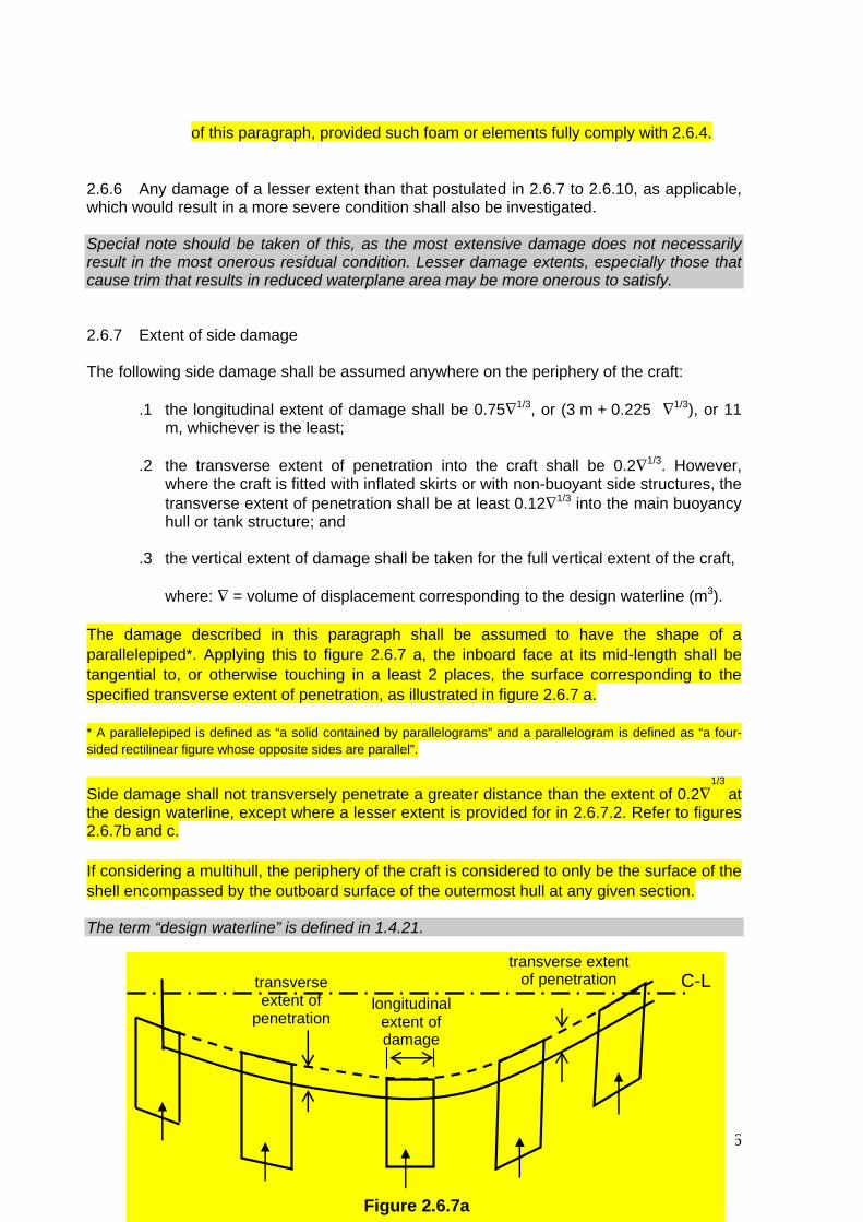
2.6.6 Any damage of a lesser extent than that postulated in 2.6.7 to 2.6.10, as applicable, which would result in a more severe condition shall also be investigated. Special note should be taken of this, as the most extensive damage does not necessarily result in the most onerous residual condition. Lesser damage extents, especially those that cause trim that results in reduced waterplane area may be more onerous to satisfy. 2.6.7 Extent of side damage The following side damage shall be assumed anywhere on the periphery of the craft:
.1 the longitudinal extent of damage shall be 0.75∇1/3, or (3 m + 0.225 ∇1/3), or 11 m, whichever is the least;
.2 the transverse extent of penetration into the craft shall be 0.2∇1/3. However,
where the craft is fitted with inflated skirts or with non-buoyant side structures, the transverse extent of penetration shall be at least 0.12∇1/3 into the main buoyancy hull or tank structure; and
.3 the vertical extent of damage shall be taken for the full vertical extent of the craft,
where: ∇ = volume of displacement corresponding to the design waterline (m3). The damage described in this paragraph shall be assumed to have the shape of a parallelepiped*. Applying this to figure 2.6.7 a, the inboard face at its mid-length shall be tangential to, or otherwise touching in a least 2 places, the surface corresponding to the specified transverse extent of penetration, as illustrated in figure 2.6.7 a.
* A parallelepiped is defined as “a solid contained by parallelograms” and a parallelogram is defined as “a four-sided rectilinear figure whose opposite sides are parallel”. Side damage shall not transversely penetrate a greater distance than the extent of 0.2∇
1/3 at
the design waterline, except where a lesser extent is provided for in 2.6.7.2. Refer to figures 2.6.7b and c. If considering a multihull, the periphery of the craft is considered to only be the surface of the shell encompassed by the outboard surface of the outermost hull at any given section. The term “design waterline” is defined in 1.4.21.
MSIS034/ CHAPTER 2/ REV 1.01/ PAGE 16
transverse extent of
penetration
transverse extent of penetration
longitudinal extent of damage
C-L
Figure 2.6.7a

MSIS034/ CHAPTER 2/ REV 1.01/ PAGE 17
Transverse extent of penetration
Damage of less than maximum vertical extent
Figure 2.6.7b
C-L
Design Waterline
Damage penetration limited below Design Waterline by a vertical line

Transverse extent of penetration
C-L
Figure 2.6.7 c
Damage penetration limited below Design Waterline by a vertical line
Design Waterline
Damage of less than maximum vertical extent
2.6.8 Extent of bow and stern damage
2.6.8.1 The following extents of damage are to be applied to bow and stern, as illustrated in figure 2.6.8:
.1 at the fore end, damage to the area defined as Abow in 4.4.1, the aft limit of which being a transverse vertical plane, provided that this area need not extend further aft from the forward extremity of the craft’s watertight envelope than the distance defined in 2.6.7.1; and
.2 at the aft end, damage to the area aft of a transverse vertical plane at a distance 0.2∇
1/3 forward of the aft extremity of the watertight envelope of the
hull.
2.6.8.2 The provisions of 2.6.6 in relation to damage of lesser extent remain applicable to such damage.
MSIS034/ CHAPTER 2/ REV 1.01/ PAGE 18
0.2∇1/3
deck area = Abow
Transverse vertical planes
Figure 2.6.8

2.6.9 Extent of bottom damage in areas vulnerable to raking damage
2.6.9.1 Application
.1 Any part of the surface of the hull(s) is considered to be vulnerable to raking damage if:
.1 it is in contact with the water at 90% of maximum speed in smooth
water, and
.2 it also lies below two planes which are perpendicular to the craft centreline plane and at heights as shown in figure 2.6.9.1.
For multihulls, individual hulls shall be considered separately.
.2 Raking damage shall be assumed to occur along any fore-and-aft line on the surface of the hull(s) between the keel and the upper limit defined in the figure below:
.3 Damage shall not be applied at the same time as that defined in 2.6.7 or
2.6.10.
This area is vulnerable to raking damage
design waterline
0.5 L
L
T0.3 T
This line is parallel to the design waterline
Figure 2.6.9.1
where: T = maximum draught of the hull (each hull considered individually in the case of multihulls) to the design waterline, excluding any non-buoyant structure, provided that structures such as single plate skegs or solid metal appendages shall be considered to be non-buoyant and thus excluded.
2.6.9.2 Extent 2.6.9.2.1 Two different longitudinal extents shall be considered separately: .1 55% of the length L, measured from the most forward point of the
underwater buoyant volume of each hull; and .2 a percentage of the length L, applied anywhere in the length of the craft,
equal to 35% for craft where L = 50m and over and equal to (L/2 + 10)% for craft where L is less than 50m.
The length L is defined in 1.4.33.
MSIS034/ CHAPTER 2/ REV 1.01/ PAGE 19

2.6.9.2.2 Except as provided below, the penetration normal to the shell shall be 0.04∇1/3 or 0.5 m, whichever is the lesser, in association with a girth along the shell equal to 0.1∇1/3, where ∇ is the volume of displacement corresponding to the design waterline (m3). However this penetration or girth shall under no circumstances extend above the vertical extent of the vulnerable area as specified in 2.6.8.1.1. 2.6.9.2.3 The shape of damage shall be assumed to be rectangular in the transverse plane as illustrated in figure 2.6.9.2 below. Damage is to be assumed at a series of sections within the defined longitudinal extent in accordance with figure 2.6.9.2, the mid-point of the damaged girth being maintained at a constant distance from the centreline throughout that longitudinal extent.
penetration normal
to the shell
girth along
the shell
Fig. 2.6.9.2
2.6.10 Extent of bottom damage in areas not vulnerable to raking damage 2.6.10.1 Application This applies to all parts of the hull(s) below the design waterline which are not defined as vulnerable to raking damage in 2.6.9.1. Damage shall not be applied at the same time as that defined in 2.6.7 or 2.6.9. 2.6.10.2 Extent The following extent of damage shall be assumed:
.1 the length of damage in the fore-and-aft direction shall be 0.75∇1/3, or (3 m + 0.225∇1/3), or 11 m whichever is the least;
.2 the athwartships girth of damage shall be 0.2∇1/3; and .3 the depth of penetration normal to the shell shall be 0.02∇1/3, where: ∇ = volume of displacement corresponding to the design waterline (m3). .4 the shape of damage shall be assumed to be rectangular in the plane of the
shell of the craft, and rectangular in the transverse plane as illustrated in figure 2.6.9.2.
MSIS034/ CHAPTER 2/ REV 1.01/ PAGE 20
The term “design waterline” is defined in 1.4.21. 2.6.11 In applying 2.6.9 and 2.6.10 to multihull craft, an obstruction at or below the design waterline of up to 7 m width shall be considered in determining the number of hulls damaged at any one time. The requirement of 2.6.6 shall also be applied. 2.6.12 Following any of the postulated damages detailed in 2.6.6 to 2.6.11, the craft in still water shall have sufficient buoyancy and positive stability to simultaneously ensure that:
.1 for all craft other than amphibious air-cushion vehicles, after flooding has ceased and a state of equilibrium has been reached, the final waterline is below the level of any opening through which further flooding could take place by at least 50% of the significant wave height corresponding to the worst intended conditions;
.2 for amphibious air-cushion vehicles, after flooding has ceased and a state of
equilibrium has been reached, the final waterline is below the level of any opening through which further flooding could take place by at least 25% of the significant wave height corresponding to the worst intended conditions;
Opening windows are included for downflooding. Non opening windows are not included for downflooding. (MSC/Circ.1102) Refer to 2.1.3.1 for a definition of downflooding point. Air-cushion vehicles are defined in 1.4.2.
.3 there is a positive freeboard from the damage waterline to survival craft embarkation positions;
.4 essential emergency equipment, emergency radios, power supplies and
public address systems needed for organizing the evacuation remain accessible and operational; and
.5 the residual stability of craft meets the appropriate criteria as laid out in
annexes 7 and 8 according to table 2.3.4. Within the range of positive stability governed by the criteria of annexes 7 or 8, no unprotected opening shall be submerged.
2.6.13 Downflooding openings referred to in 2.6.12.1 and 2.6.12.2 shall include doors and hatches which are used for damage control or evacuation procedures, but may exclude those which are closed by means of weathertight doors and hatch covers and not used for damage control or evacuation procedures. 2.7 Inclining and stability information 2.7.1 Every craft, on completion of build, shall be inclined and the elements of its stability determined. When an accurate inclining is not practical, the lightweight displacement and centre of gravity shall be determined by a lightweight survey and accurate calculation. 2.7.2 On all craft, where an accurate inclining experiment is impractical owing to the height of the centre of gravity (VCG or KG) being less than one third of the transverse metacentric
MSIS034/ CHAPTER 2/ REV 1.01/ PAGE 21

height (GMT), the Administration may accept estimation of KG by detailed calculation in place of an inclining experiment. In such cases, a displacement check shall be undertaken to confirm the calculated lightship characteristics, including LCG, which may be accepted if the measured lightship displacement and LCG are respectively within 2% and 1% L relative to the estimate. 2.7.3 The master shall be supplied by the owner with reliable information relating to the stability of the craft in accordance with the following provisions of this paragraph. The information relating to stability shall, before being issued to the master, be submitted to the Administration for approval, together with a copy thereof for their retention, and shall incorporate such additions and amendments as the Administration may in any particular case require. 2.7.4 Where any alterations are made to a craft so as significantly to affect the stability information supplied to the master, amended stability information shall be provided. If necessary, the craft shall be re-inclined. 2.7.5 A report of each inclining or lightweight survey carried out in accordance with this chapter and of the calculation therefrom of the lightweight condition particulars shall be submitted to the Administration for approval, together with a copy for their retention. The approved report shall be placed on board the craft by the owner in the custody of the master and shall incorporate such additions and amendments as the Administration may in any particular case require. The amended lightweight condition particulars so obtained from time to time shall be used by the master in substitution for such previously approved particulars when calculating the craft's stability. 2.7.6 Following any inclining or lightweight survey, the master shall be supplied with amended stability information if the Administration so requires. The information so supplied shall be submitted to the Administration for approval, together with a copy thereof for their retention, and shall incorporate such additions and amendments as the Administration may in any particular case require. 2.7.7 Stability information demonstrating compliance with this chapter shall be furnished in the form of a stability information book which shall be kept on board the craft at all times in the custody of the master. The information shall include particulars appropriate to the craft and shall reflect the craft loading conditions and mode of operation. Any enclosed superstructures or deck-houses included in the cross curves of stability and the critical downflooding points and angles shall be identified. At the operating station there shall be plans showing clearly for each deck and hold the boundaries of the watertight compartments, the openings therein with their means of closure and position of any controls thereof. 2.7.8 Every craft shall have scales of draughts marked clearly at the bow and stern. In the case where the draught marks are not located where they are easily readable, or operational constraints for a particular trade make it difficult to read the draught marks, then the craft shall also be fitted with a reliable draught-indicating system by which the bow and stern draughts can be determined. For amphibious air-cushion vehicles this may be achieved by the use of draught gauges in conjunction with deck datum plates.
However, due to the buoyancy of the submerged skirts and air entrapped in them and under the craft, this is not a reliable method of checking the weight of an ACV. 2.7.9 The owner or builder, as appropriate, shall ensure that the positions of the draught marks are accurately determined and that the marks are located on the hull in a permanent
MSIS034/ CHAPTER 2/ REV 1.01/ PAGE 22
manner. Accuracy of the draught marks shall be demonstrated to the Administration prior to the inclining experiment. 2.8 Loading and stability assessment On completion of loading of the craft and prior to its departure on a voyage, the master shall determine the trim and stability of the craft and also ascertain and record that the craft is in compliance with stability criteria of the relevant requirements. The Administration may accept the use of an electronic loading and stability computer or equivalent means for this purpose. In certain cases, it may be acceptable for vessels to be exempted from the requirement to calculate loading and stability prior to departure. Examples of where an exemption may be considered are as follows: 1. Where a vessel makes regular voyages to and from the same place in conditions of loading which correspond closely to conditions in the approved Stability Information Booklet. 2. Where the maximum deadweight which a ship is capable of carrying does not exceed x tonnes / y % lightship displacement. Values of x and y can be attained from MCA Vessel Policy Branch. 3. Where the actual draught / deadweight does not exceed z % of the subdivision draught / maximum. Values of z can be attained from MCA Vessel Policy Branch. In cases 1 - 3 the following procedures should be put in place: - Before the ship departs port, confirmation will be required that the actual condition of loading corresponds closely to one of the approved loading conditions contained in the Stability Information Book. - The approved loading condition corresponding to the actual loading condition is to be recorded in a book retained on board for this purpose. - The approved loading conditions should reflect the vessels normal operating pattern and should display sufficient reserve below the maximum allowable KG to account for minor variations in trim, cargo distribution and free surface moment etc. 4. Where the approved loading conditions assume a pessimistic (high) VCG for cargo and it is shown that the maximum allowable VCG cannot be exceeded in any practical loading condition. - In these cases, it will be sufficient for the Master to determine the draught and trim prior to departure and confirm that these lie within the limiting range. - The actual draught and trim should be recorded in a book retained onboard for this purpose. It should be noted that when the vessel carries cargo items which cannot readily be confirmed as having a VC below the cargo VC assumed in the approved loading conditions, a full calculation of the intended loading condition must be made prior to departure, using the procedure contained in the approved Stability Information Booklet. Owners wishing to exercise these options are advised to refer their proposals to MCA Vessel Policy Branch. Reference should also be made to section 5.5 MCA Instructions for
MSIS034/ CHAPTER 2/ REV 1.01/ PAGE 23

the Guidance of Surveyors, Passenger Ship Construction - Classes I, II & II(A) which contains extensive guidance on this subject. 2.9 Marking and recording of the design waterline 2.9.1 The design waterline shall be clearly and permanently marked on the craft’s outer sides by the load line mark described below. This and the reference line described in 2.9.2.2 below shall be recorded in the High-Speed Craft Safety Certificate. For craft where this is not practical, e.g. amphibious air-cushion vehicles fitted with peripheral skirts, defined deck reference points shall be provided, from which the freeboard can be measured, and hence the draughts obtained. 2.9.2 Load line mark 2.9.2.1 The load line mark shall consist of a ring with an outside diameter of 300 mm and width of 25 mm which is intersected by a horizontal line of length 450 mm and having a breadth of 25 mm, the upper edge of which passes through the centre of the ring. The centre of the ring shall be placed at the longitudinal centre of flotation in the displacement mode and at a height corresponding to the design waterline. 2.9.2.2 To assist in verifying the position of the load line mark, a reference line shall be marked on the hull at the longitudinal centre of flotation by a horizontal bar having a length of 300 mm and a breadth of 25 mm and having the upper edge corresponding to the reference line. 2.9.2.3 Where practicable, the reference line should be related to the uppermost deck at side. Where it is not possible, the position of the reference line should be defined from the underside of keel at the longitudinal centre of flotation. 2.9.2.4 The mark of the Authority by whom the load lines are assigned may be indicated alongside the load line ring above the horizontal line which passes through the centre of the ring, or above and below it. This mark shall consist of not more than four initials to identify the Authority’s name, each measuring approximately 115 mm in height, and 75 mm in width. 2.9.2.5 The ring, lines and letters shall be painted in white or yellow on a dark ground or in black on a light ground, and permanently marked. The marks shall be plainly visible. 2.9.3 Verification The High-Speed Craft Safety Certificate shall not be delivered until the Administration has verified that the marks are correctly and permanently indicated on the sides of the craft.
PART B - REQUIREMENTS FOR PASSENGER CRAFT 2.10 General Where compliance with this chapter requires consideration of the effects of passenger weight, the following information shall be used:
.1 The distribution of passengers is 4 persons per square metre.
MSIS034/ CHAPTER 2/ REV 1.01/ PAGE 24 .2 Each passenger has a mass of 75 kg.

.3 Vertical centre of gravity of seated passengers is 0.3 m above seat.
.4 Vertical centre of gravity of standing passengers is 1 m above deck.
.5 Passengers and luggage shall be considered to be in the space normally at
their disposal.
.6 Passengers shall be distributed on available deck areas towards one side of the craft on the decks where assembly stations are located and in such a way that they produce the most adverse heeling moment.
.7 Passengers assumed to be occupying seats shall be taken as having a
vertical centre of gravity corresponding to being seated, with all others standing.
.8 On the decks where assembly stations are located, the number of passengers on each deck shall be that which generates the maximum heeling moment. Any remaining passengers shall be assumed to occupy decks adjacent to those on which the assembly stations are located, and positioned such that the combination of number on each deck and total heeling moment generate the maximum static heel angle.
.9 Passengers shall not be assumed to gain access to the weather deck nor be assumed to crowd abnormally towards either end of the craft unless this is a necessary part of the planned evacuation procedure.
.10 Where there are seats in areas occupied by passengers, one passenger per seat shall be assumed, passengers being assigned to the remaining free areas of the deck (including stairways, if appropriate) at the rate of four per square metre.
2.11 Intact stability in the displacement mode The craft shall have sufficient intact stability that, when in still water conditions, the inclination of the craft from the horizontal would not exceed 10º (under all permitted cases of loading* and uncontrolled passenger movements as may occur). * Attention is drawn to the longitudinal centre-of-gravity limitations established in compliance with 17.3. Variations in permissible trim are most often derived from the safe handling characteristics at speed derived from the trials required by chapter 17. 2.12 Intact stability in the non-displacement mode 2.12.1 The total heel angle in still water due to the effect of passenger movements or due to beam wind pressure as per 1.1.4 of annex 6 shall not exceed 10º. Passenger movement need not be considered where passengers are required to be seated whenever the craft is operating in the non-displacement mode.
MSIS034/ CHAPTER 2/ REV 1.01/ PAGE 25

2.12.2 In all loading conditions, the outward heel due to turning shall not exceed 8º, and the total heel due to beam wind pressure as per 1.1.4 of annex 6 and due to turning shall not exceed 12º outward. 2.12.3 Demonstrating the effect of the passenger heeling moment calculated as given by 2.10 above, or a defined beam wind pressure when at speed, shall be established by conducting a trial or model test with an equivalent heeling moment applied by test weights. Passenger movement may only be neglected on craft where the safety announcement (refer to 8.4.1 and 18.7) expressly requires passengers to remain seated throughout the voyage. 2.13 Buoyancy and stability in the displacement mode following damage 2.13.1 Following any of the postulated damages detailed in 2.6.6 to 2.6.10, in addition to satisfying the requirements of 2.6.11 and 2.6.12, the craft in still water shall have sufficient buoyancy and positive stability to simultaneously ensure that:
.1 the angle of inclination of the craft from the horizontal does not normally exceed 10º in any direction. However, where this is clearly impractical, angles of inclination up to 15º immediately after damage but reducing to 10º within 15 min* shall be permitted provided that efficient non-slip deck surfaces and suitable holding points, e.g., holes, bars, etc., are provided; and
* Refer to the Recommendations on a standard method for establishing compliance with the requirements for cross-flooding arrangements in passenger ships adopted by the Organization by resolution A.266(VIII) as amended.
.2 any flooding of passenger compartments or escape routes which might occur will not significantly impede the evacuation of passengers.
Flooding of passenger compartments or escape routes which exceeds a depth of 0.2m at the equilibrium waterline in calm water is considered to significantly impede evacuation. No flooding of escape routes is acceptable on craft where these escape routes include a door. It is not intended to apply dry shod evacuation in the case of full raking damage situations. 2.13.2 In addition to the requirements in 2.13.1, category B craft shall also satisfy the following criteria after sustaining raking damage of 100% of length L, having the girth and penetration given in 2.6.8.2.2, to any part of the surface of the hull(s) defined in 2.6.8.1:
.1 the angle of inclination of the craft from the horizontal shall not exceed 20° in the equilibrium condition;
.2 the range of positive righting lever shall be at least 15° in the equilibrium
condition; .3 the positive area under the righting lever curve shall be at least 0.015 m-rad
in the equilibrium condition; .4 the requirements of 2.6.11.3 and 2.13.1.2 are satisfied; and
The requirements of 2.13.1.2 should be reviewed on a case by case basis for the 100% length damage situation. MCA headquarters will review the appropriateness and practicality of all evacuation routes satisfying 2.13.1.2.
MSIS034/ CHAPTER 2/ REV 1.01/ PAGE 26

.5 in intermediate stages of flooding, the maximum righting lever shall be at least 0.05 m and the range of positive righting lever shall be at least 7°.
In complying with the above, the righting lever curve shall be terminated at the angle of downflooding, and only one free surface need be assumed. 2.14 Inclining and stability information 2.14.1 At periodical intervals not exceeding 5 years, a lightweight survey shall be carried out on all passenger craft to verify any changes in lightweight displacement and longitudinal centre of gravity. The passenger craft shall be re-inclined whenever, in comparison with the approved stability information, a deviation from the lightweight displacement exceeding 2%, or a deviation of the longitudinal centre of gravity exceeding 1% of L is found or anticipated. 2.14.2 A report of each inclining or lightweight survey carried out in accordance with 2.7.1 and of the calculation therefrom of the lightweight condition particulars shall be submitted to the Administration for approval, together with a copy for their retention. The approved report shall be placed on board the craft by the owner in the custody of the master and shall incorporate such additions and amendments as the Administration may in any particular case require. The amended lightweight condition particulars so obtained from time to time shall be used by the master in substitution for such previously approved particulars when calculating the craft's stability. 2.14.3 Following any inclining or lightweight survey, the master shall be supplied with amended stability information if the Administration so requires. The information so supplied shall be submitted to the Administration for approval, together with a copy thereof for their retention, and shall incorporate such additions and amendments as the Administration may in any particular case require.
PART C - REQUIREMENTS FOR CARGO CRAFT 2.15 Buoyancy and stability in the displacement mode following damage Following any of the postulated damages detailed in 2.6.6 to 2.6.10, in addition to satisfying the requirements of 2.6.11 and 2.6.12, the craft in still water shall have sufficient buoyancy and positive stability to simultaneously ensure that the angle of inclination of the craft from the horizontal does not normally exceed 15º in any direction. However, where this is clearly impractical, angles of inclination up to 20º immediately after damage but reducing to 15º within 15 min* may be permitted provided that efficient non-slip deck surfaces and suitable holding points are provided. * Refer to the Recommendations on a standard method for establishing compliance with the requirements for cross-flooding arrangements in passenger ships adopted by the Organization by resolution A.266(VIII) as amended. 2.16 Inclining Where it is satisfied by lightweight survey, weighing or other demonstration that the lightweight of a craft is closely similar to that of another craft of the series to which 2.7.1 has been applied, the Administration may waive the requirement of 2.7.1 for craft to be inclined.
MSIS034/ CHAPTER 2/ REV 1.01/ PAGE 27

In this regard, a craft which lies within the parameters of 2.14.1, when compared with a craft of the series which has been inclined, shall be regarded as being closely similar to that craft.
MSIS034/ CHAPTER 2/ REV 1.01/ PAGE 28