CHAPTER 1open_jicareport.jica.go.jp/pdf/11633864_02.pdf · erection work. The temporary ... been...
186
CHAPTER 1
Transcript of CHAPTER 1open_jicareport.jica.go.jp/pdf/11633864_02.pdf · erection work. The temporary ... been...

CHAPTER 1

CHAPTER 3

3-1
Chapter 3 Implementation Plan
3-1 Implementation Plan
3-1-1 Implementation concept
The implementation plan of this project is proposed while taking survey results into
account and assuming that the plan is implemented with financing by issuance of national bonds. 1)Establishment of the implementation period
The project content includes, for both bridges, preparatory work, construction road work during the work period, bridge work (substructure, superstructure, bridge appurtenances), approach road work, revetment work, and miscellaneous works. The total work period, which will be about 24 months will commence in September 2001 and be completed and delivered in September 2003. Four months from the middle of April to the middle of June and from October to November of the work period are rainy seasons, during which, as a rule, bridge substructure work will not be done. Only fabrication of superstructure girders can be done even in rainy seasons. 2)Work construction method
The flow of typical work as a whole is shown in Fig.-3.1.1 (common to Gampola Bridge and Muwagama Bridge).
(1)Construction road work
Ordinary vehicles will use the existing bridge while bridge reconstruction is under way. However, a construction road must be provided to enable access to the work site.
(2)Temporary landing bridge construction work
A temporary landing bridge for access is necessary during pier and superstructure erection work. The temporary landing bridge will be made from H-steels, with repair expected about once every four to five months.

3-2
(3)Construction of foundation
Based on the result of boring survey, the foundation structures of the bridges concerned will be as follows.
Table-3.1.1 Construction of foundation Foundation No. Bridge name
Spread foundation Pile foundation
No.93 Gampola Bridge ・Abutment on the left bank ・Piers
・Abutment on the right bank
No.239 Muwagama Bridge ・Not applicable ・Abutments on left and right banks ・Piers
Based on the result of a boring survey, it was decided that the two bridges covered by this project would employ either piles or spread foundation. In the case of pile foundation, the cast-in-place pile method described below is used as a method appropriate to the strata of Sri Lanka.
①The reverse circulation method, in which excavation is done while applying water
pressure caused by head difference to stabilize the bore wall ②The all-round rotation type all-casing method, in which excavation is done while
protecting the bore wall with a casing
In both methods, pre-assembled rebars (cage) is immersed and underwater concreting is made in the specified position. In this basic design, the reverse circulation method is assumed as a result of a comparative review because of economic feasibility. The excavation machine and slurry treatment facilities will be procured (or imported) from Japan to be carried into the site.
In the case of both bridges, the existing bridges are secured for traffic until the new bridges are completed. Accordingly, the work is conducted in the proximity of the existing bridges. It is essential to conduct the work while securing necessary distances and paying due attention to the effects on the neighborhood of driving foundation piles.

3-3
(4)Substructure work
For the substructure, an inverted-T type abutment is most advantageous in terms of economy. Basically, the substructure work will be done in the river. The method described below is employed commonly for both bridges.
① Excavation carried out after closure with sheet-piles. ② Use a backhoe for excavation. When the excavation depth is expected to be 5m
or deeper, either a clamshell or small backhoe should be used. Provide waling and struts in the specified position, and carefully proceed with excavation with care while avoiding excavation prior to provision of waling and struts.
③ After reaching the specified depth, level the excavation base surface manually,
lay broken and crushed stones, and place concrete to the designated height. ④ After pile head treatment, proceed with re-bar assembling, form setup, and
concrete placement for footing, columns, and girders in this order, erecting the substructure.
⑤ Remove struts and waling while carrying out filling with specified filler
materials to the specified thickness. ⑥ When filling reaches the specified height of ground level, carry out thorough
filling of the surrounding ground and remove sheet-piles. Take due care to prevent subsidence when removing sheet-piles.
⑦ Carry out the revetment work (gabions, wire mats, etc.)
As the work in the river is susceptible to natural disasters (high water, etc.),
implementation should be avoided during the rainy season. No work should be done during periods of heavy rain. (5) Construction of the superstructure
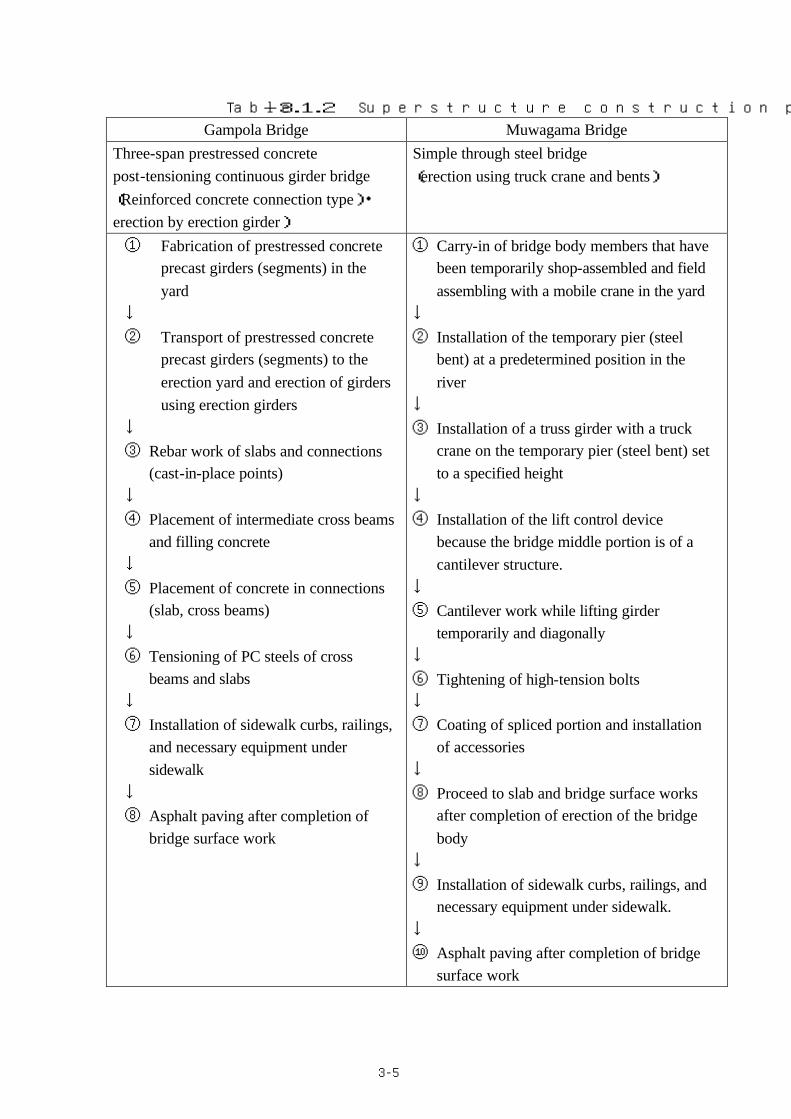
The construction procedure for the superstructure is outlined in table 3.1.2 for an expected prestressed concrete connected continuous girder bridge (reinforced concrete connection) and a steel bridge (Trussed Langer).

3-4
Start Preparatory work Diversion work Improved yard work Foundation pile driving (Bridge superstructure) Cofferdam Excavation Girder manufacture Substructure work (Road) (Revetment・stream bed protection)
Girder erection Clearing/grubbing Clearing/grubbing
Slab work Base course work Stream bed protection
Bridge surface work Pavement Revetment
Diversion removal Slope work Clearing End
Fig.-3.1.1 Work flow chart
3-5
Table-3.1.2 Superstructure construction procedure Gampola Bridge Muwagama Bridge
Three-span prestressed concrete post-tensioning continuous girder bridge (Reinforced concrete connection type)・erection by erection girder)
Simple through steel bridge (erection using truck crane and bents)
① Fabrication of prestressed concrete precast girders (segments) in the yard
↓ ② Transport of prestressed concrete
precast girders (segments) to the erection yard and erection of girders using erection girders
↓ ③ Rebar work of slabs and connections
(cast-in-place points) ↓ ④ Placement of intermediate cross beams
and filling concrete ↓ ⑤ Placement of concrete in connections
(slab, cross beams) ↓ ⑥ Tensioning of PC steels of cross
beams and slabs ↓ ⑦ Installation of sidewalk curbs, railings,
and necessary equipment under sidewalk
↓ ⑧ Asphalt paving after completion of
bridge surface work
① Carry-in of bridge body members that have been temporarily shop-assembled and field assembling with a mobile crane in the yard
↓ ② Installation of the temporary pier (steel
bent) at a predetermined position in the river
↓ ③ Installation of a truss girder with a truck
crane on the temporary pier (steel bent) set to a specified height
↓ ④ Installation of the lift control device
because the bridge middle portion is of a cantilever structure.
↓ ⑤ Cantilever work while lifting girder
temporarily and diagonally ↓ ⑥ Tightening of high-tension bolts ↓ ⑦ Coating of spliced portion and installation
of accessories ↓ ⑧ Proceed to slab and bridge surface works
after completion of erection of the bridge body
↓ ⑨ Installation of sidewalk curbs, railings, and
necessary equipment under sidewalk. ↓ ⑩ Asphalt paving after completion of bridge
surface work

3-6
(6)Approach road work
① Remove existing asphalt.
② Carry out embankment with borrow material to the specified position to make up the filled-up ground.
③ Carry out sufficient rolling compaction of the filled-up ground.
④ Construct drainage, such as drain gutters, crossing drain pipes, etc.
⑤ Place and spread the base course material (crushed stones) to the specified thickness and carry out sufficient rolling compaction with a tire roller.
⑥ Remove loose stones, dust, and other foreign material from the base course surface (spread surface) and apply asphalt manually with an engine sprayer.
⑦ Use an asphalt finisher for leveling to the specified thickness. Carry out initial rolling with a macadam roller and secondary rolling with a tire roller.
⑧ Provide lines such as a center line, marginal strips, etc. Traffic Safety control devices, including signs, etc. must also be provided.
3)Utilization of local engineers and materials/equipment
Excellent engineers are employed by RDA and private enterprises. Considering
that semi-government enterprises are capable of performing fabrication up to erection of prestressed concrete girders, the technology level cannot be assumed to be low. However, there is a disparity in terms of quality with advanced countries.
Construction machinery in Sri Lanka has almost no versatility. Heavy machines such as cranes are limited in quantity and leasing becomes difficult depending on convergence of works. Therefore, they are to be brought into Sri Lanka from a third country or Japan. The plan calls for checking and utilizing available equipment as much as possible.
4)Employment of local contractors
Local contractors are not yet sufficiently developed in terms of technical capacity.
For types of work that do not require special technology, these contractors will have an
3-7
opportunity to participate as subcontractors under the supervision and guidance of Japanese contractors, thereby contributing to the development of construction engineering in Sri Lanka. 5)Dispatch of engineers from Japan
Engineers will be dispatched from Japan for the following types of work for supervision and execution of work in the field:
① Prestressed concrete work : Fabrication of prestressed concrete girders,
prestressing work of prestressed concrete, girder erection ② Scaffolding work:Erection for steel bridge, special scaffolding ③ Painting:Guidance on painting of steel bridge ④ Operation(plant) ⑤ Operation(cast-in-place piles)

83-
3-1-2 Implementation conditions
The implementation concept assumes that the plan is feasible and takes into account the meteorological conditions (dry and wet seasons) unique to Sri Lanka and materials/equipment procurement situations. 1)Work schedule considers wet and dry seasons
Sri Lanka’s dry and wet seasons are clearly identifiable. The type of work whose operating rate significantly declines during the rainy seasons from April to October, such as foundation and bridge substructure works, must be implemented during the dry season as much as possible. It is also necessary to establish an equipment application plan based mainly on implementation during the dry season. It will be best to start preparatory work and to set up the work base immediately after conclusion of the contract between the Sri Lanka partner and contractor. Since transport of equipment from Japan uses irregular service via Singapore and requires 1.5 to 2.5 months, this project will plan for transport accordingly.
2)Bringing construction material to the site
Construction materials to be carried to the site are transported mainly by land.
Materials that are difficult to procure in Sri Lanka are imported from foreign countries and transported to the site via the port of Colombo in the case of import by sea or via Katunayake International Airport in case of import by air.
(1) By land
Nearly all materials procurable in Sri Lanka are found in the Colombo area, and imported materials are collected in the port of Colombo. It is therefore necessary to secure an access route from Colombo to the sites.
① Access to the Gampola Bridge
The main trunk line, Route A5, connects Kandy, the second largest city about 115 km northeast of Colombo with Nuwara Eliya in the central highland. The Gampola Bridge exists at a point where this route crosses the Mahaweli River with the largest drainage area in Sri Lanka at a point about 20 km southward from Kandy toward Nuwara Eliya.

93-
② Access to the Muwagama Bridge
The Muwagama Bridge exists at a point where the route crosses the Kalu River after passing through Ratnapura City about 100 km southeast of Colombo via Route A-4 to enter the B390 road. The bridge is 2 km to the southwest.
(2) By sea
All materials and equipment to be imported by sea from foreign countries are unloaded in Colombo Port to be transported by the inland route described above. In the case of procurement from Japan, it will take about 1.5 to 2 months from shipment in Japan to arrival at the site.
(3) By air
Materials and equipment to be imported by air from foreign countries are unloaded at Katunayake International Airport to be transported into Colombo via Route A-3 and finally to the site via the above route.
(4) Customs clearance
Materials and equipment not procurable in Sri Lanka will be imported from Japan. Though they are not taxable by customs duties, etc. thanks to ODA tax benefits, it is impossible to obtain direct tax exemption in Sri Lanka. Accordingly, RDA, the implementing agency, will budget the amount equivalent to the tax exemption and refund the paid tax to contractors. As the obligation of contractors to bear interest covers the refund period, the list of import materials and equipment and the tax incidence amount must be submitted to RDA to allow RDA to establish beforehand the budget, including the tax amount. * Preparation and submission of the master list of materials and equipment to be
imported * Approval of authorities concerned of Sri Lanka on the master list * When imported materials and equipment have entered Sri Lanka, they are
transported to the site after customs clearance by paying taxes such as import duties, etc. for taxable materials and equipment. During customs clearance, a National Security Levy (NSL) and Goods and Services Tax (SGT) are levied in addition to the import duties. The GST tax rate is currently 12.5%.

103-
3) Acquisition of land necessary for construction and transfer/removal of
obstructions
Securing of the land necessary for the work and transfer/removal of obstructions are included among the obligations of the recipient country. There is a division of the implementing RDA organization in charge of securing the land. This division proceeds with all procedures to secure land related to the RDA project. The same procedure is used to secure land necessary for construction of the bridges. As utilities, such as electricity, telephone, water, etc. require coordination with authorities concerned, it is planned to proceed with removal and transfer, if necessary, through RDA.
① Acquisition of the land and transfer/removal of obstruction facilities, etc.
On the basis of the field survey result, ministries concerned of the Sri Lanka Government will undertake transfer and recovery of public installations that are obstructions to securing the land and construction. Table-3.1.3 and 3.1.4 outlines the land to be secured and facilities to be transferred.
Table-3.1.3 Outline of land to be secured Item No.93 Gampola Bridge No.239 Muwagama Bridge During implementation /bridge construction
During implementation
Bridge construction
During implementation
Bridge construction
Left bank
- Shop:1 - Houses:11 Private
Right bank
- - - Houses:2
Left bank
- School:4 Local road(Class E)
- Public
Right bank
Community hall
- Local road(Class E)
-

113-
Table-3.1.4 Facilities to be transferred Item Authorities
concerned Gampola Bridge Muwagama Bridge
Electricity Ceylon Electric Board
High voltage:11kv(before and after implementation)
Low voltage:230v(after implementation)
High voltage:33kv(after implementation) Low voltage:230v(after implementation)
Water supply National Water Supply & Drainage Board
φ 225mm(after implementation) φ 150mm(after implementation)
φ 225mm(after implementation) φ 150mm(after implementation) φ 100mm(after implementation)
Telephone
Sri Lanka Telecom
φ 150mm buried cable(after implementation)
overhead line(after implementation)
φ 100mm buried cable(after implementation) φ 75mm buried cable(after implementation)
Others
Poles Telephone switchboard(unit board)
Poles
Transfer cost (Rs.million)
1.0 0.7
② Temporary sites for work
During the work period, temporary sites must be secured for temporary buildings and equipment and for storage of materials and equipment.
Possible candidate sites and uses are shown in Table-3.1.5.

123-
Table-3.1.5 Temporary sites for work
No.93 Gampola Bridge No.239 Muwagama Bridge
Candidate sites
Left bank (school yard, public domain) of upstream and
downstream sides of the existing bridge, work platform.
Left and right banks (private land) of downstream side of the existing
bridge
Use
Approach road, field office, construction material storage yard,
machine storage site, various plants.
Detour from the existing road, temporary road, field office,
construction materials and machine storage yard, various plants
Item Temporary yard, Landing bridge and
yard Temporary yard
③ Diversion road
On the Muwagama Bridge side, the existing road for daily activities runs through the site scheduled for construction. This road will be completely closed during the work, and a diversion road must be provided as shown in Table-3.1.6 because the original functions of the existing one must be restored after the work.
Table-3.1.6 Diversion road
No.93 Gampola Bridge No.239 Muwagama Bridge
Location and specifications of diversion
road
Not required as the result discussions with RDA
Length:about 30M on the left bank、
about 50M on the right bank,
Specifications NA
Road class: Class E(local road)
width (Class E)=Total width 4M(existing width)、with asphalt
pavement

133-
④ Blocking traffic
The basic plan is to leave the existing bridge after construction of the new one, so that there is no need to block the existing traffic. Traffic will be blocked however subject to approval of authorities concerned if required due to deadhead of large vehicles (during girder transport or erection), construction of a temporary approach road, etc.
Traffic will be blocked, if necessary, in the nighttime when the traffic volume is small, with necessary notice boards, protection equipment, and traffic guides provided to ensure thorough safety measures.
⑤ Customs clearance
Materials and equipment procured from Japan will be brought into Sri Lanka mainly via Singapore. It is necessary to obtain understanding of Sri Lanka Government beforehand to ensure smooth customs clearance.
⑥ Safety measures
Both bridges will have a field office and accommodation facilities. Guards will also be assigned to protect equipment and material and to guide the traffic during the work.

143-
Table-3.1.7 Safety measures for Construction Safety measures No. Name of
bridge Work control Material/equipment control
No.93 Gampola Bridge
Safety measures are indispensable because transport/erection of heavy materials and structures at elevated places are made near the existing bridge. Piers are constructed using a temporary landing bridge, with large number of work vehicles running on the landing bridge. Therefore, measures to prevent falling are necessary.
No.239 Muwagama Bridge
Market and housing areas exist near the bridge, and traffic is heavy. During transport of materials and equipment and deadhead of heavy machinery, guards will be provided to ensure the safety of pedestrians and the neighborhood. As the work is done in the proximity to the existing bridge, due care will be necessary to prevent contact with the existing bridge and accessories, bridge attachments, etc. during slinging, concrete placement from hopper, etc.
It is planned to provide the field office at a bridge location. As the urban area is nearby, communications with telephone sets within the city is possible. As indiscriminate terrorism is possible, the staff will always carry wireless transceivers to ensure the adequate communications.
Guards will also be provided for the site and material/equipment control in the nighttime to prevent theft, etc.
3-1-3 Scope of Works
The cost of construction of the bridge main body and approach road for the project will be totally borne by the Japanese side.

153-
3-1-4 Consultant supervision
Japanese staff in charge of general affairs, bridges (planning, superstructure,
substructure), roads, survey of natural conditions, and bid documents will handle detailed design, preparation of bid documents, and bidding after conclusion of the consultant agreement. During the work period, the consultant will dispatch the Japanese resident supervisor and the staff for supervision and guidance for major work to the site. Principal assignments of the staff are described below.
1) Chief executive
In charge of broad range of duties related to detailed design, bidding, and supervision
2) Bridge(Planning, superstructure、substructure)
In charge of design of superstructure, substructure, foundation, temporary works, and erection accessory works according to individual assignment, as well as drafting and quantity calculation, in the phase of detailed design. During the work, the bridge staff is in charge of supervision, witnessing and inspection of each type of work.
3) Road (road design)・road construction
In charge of design for the access road rehabilitation plan as well as plotting and quantitative calculations according to individual assignments in the phase of detailed design. During the work, the staff is in charge of supervision, witnessing, and inspection of embankments, base courses, and pavement, which exert considerable influence on the quality of completed facilities.
4) Bid documents
The staff prepares bid documents and contracts for bidding and contract duties in the phase of detailed design
5) Resident supervisor
Stationed at the site from commencement to completion of the project and in charge of technical matters such as quality control, process control, safety control, etc. and a series of clerical duties. During construction of the bridge, the supervisor is also in charge of supervision and joint inspections of bridge main body, base courses,

163-
pavement, and accessory works.
6)Bridge works(superstructure and substructure)
In charge of technical and clerical duties related to quality, process, and safety controls for each type of bridge work. During construction of the bridge, the consultant staff is also in charge of supervision and joint inspections of bridge main body, base courses, pavement, and appurtenant work.
3-1-5 Procurement plan
1)Labor condition
Though described as a Buddhist country, Sri Lanka contains other religions.
Understanding and coordination with local religions and practices in the course of labor control is considered the greatest factor for successful completion of the project.
Understanding of the saying that laborers stick together is essential.
(1) Construction engineers
Among construction technicians, engineer-class technicians are graduates from two universities; Peradenia University and Moratuwa University. Every year, about 1,500 are graduated from these universities, of which about 100 are civil engineers. Apart from these universities, one vocational college and industrial high school exist on average in each district, which send out technicians every year.
(2) Laborers from third countries
In Sri Lanka, third country nationals can rather easily obtain work visas. The Government is also making efforts to introduce excellent technology from overseas. It is said that the advance of enterprises from India, Korea, China, Singapore, USA, and Europe as well as from Japan is increasing yearly. However, ordinary laborers have difficulty entering to work.
(3) Sri Lanka Laws concerning employment
There is an employment law covering enterprises that employ local laborers. Conditions considered important for employment are summarized below.

173-
Table-3.1.8 Sri Lanka law concerning Employment ① Wage system: Two systems exist: ENGINEERING TRADE(hereinafter
called “ET”) and HOPE&OFFICE EMPLOYEE (hereinafter
called “SOE”). ET and SOE include following occupations; ET
… technical (electric engineer, mechanical engineer, civil
engineer, building engineer, service engineer, store keeper),
physical labor (earth worker, driver, carpenter, cleaner, guards
SOE…Clerical (clerk, typist, office worker). Note that the
above classification is interpreted differently among enterprises
and thus not absolute.
② Work hours: 48 hours per week
③ Days off and legal
holidays:
All workers are allowed to have one day off per week.
Workers receiving monthly pay are allowed to have days off
equivalent to nine legal holidays. If they work on such a day
off, the payment for the day is doubled. In addition, a
substitute holiday is allowed later. If they work on a holiday
or festival day, the payment is multiplied by 1.5 for initial eight
hours and doubled for hours exceeding eight hours.
④ Annual vacation Absence with leave for 14 days is allowed for workers
generally working 288 days a year. For SOE, special
absence with leave for seven days is additionally allowed.
⑤ Absence due to
sickness
When a medical certificate of a designated medical doctor is
submitted within one year of service, absence due to sickness
for seven to 14 days is allowed. Payment during this period is
guaranteed.
⑥ Absence due to
accident
In case of injury due to accident while on duty, absence due to
accident is allowed for seven days a year. Absence
exceeding the seven-day period is covered by labor
insurance.
⑦ Overtime
compensation
Overtime compensation is calculated as follows and paid:
(A) Hourly overtime rate is calculated as follows for those
receiving monthly pay:
・ET………Overtime payment per hour=Monthly payment
/200 hours
・SOE……Overtime payment per hour=Monthly payment/
240 hours
(B) Hourly rate for overtime compensation is calculated as
follows for those receiving daily pay

183-
・ET………Overtime pay per hour=Daily payment/8
hours
・SOE……Overtime pay per hour=Daily payment/8
hours
(C) Overtime compensation is equivalent to 1.5-fold
payment.
⑧ Retirement,
disemployment
Retirement and disemployment must always be justified by
proper reason. Reasons are classified as follows in terms of
law and practices:
(A) LAY-OFF :Downsizing because of
surplus manpower because
the peak time of work is over.
(B) RESIGNATION :Retirement due to the
worker’s own reason.
(C)VACATION OF POST :When the worker is absent
from the job without
approval for a long time
(D) TERMINATION :When the worker
performance is inadequate
or causes an accident
For (A), the disemployment list and statement of reason must
be submitted to the Labor Standards Office. When the Office
issues approval of disemployment, the company submits “One
Month Notice” to the staff concerned for disemployment. For
(D), the company disemploys the worker immediately and
reports it to the Labor Standards Office.
⑨ Pension program 15% of the total compensation is paid to the employee as a
pension.

3-
19
(4) Number of operating days per month
Table-3.1.9 No. of working days per month
No. of days with
precipitation of
10mm or more
Month Weekd
ay
Sunday Saturd
ay
Holiday
( )*1
Gampola Muwagama
Remarks
1 18 5 5 2(3) 2.0 3.8
2 19 4 4 1(2) 2.0 2.8
3 23 4 4 0(0) 3.6 6.6
* 2 No. of days with
average rainfall in dry
season:
Gampola:6.7 days/month
Muwagama :6.2 days /
month
4 16 4 4 1(6) 9.2 10.0
5 18 5 4 0(4) 7 12.2
6 21 4 4 1(1) 11 13.4
7 20 5 5 1(1) 12.8 9.8
8 22 4 4 1(1) 10.4 9.4
9 21 4 4 1(1) 9.2 12.4
10 20 5 5 1(1) 11 11.8
* 2 No. of days with
average rainfall in
rainy season:
Gampola :10.1 days /
month
Muwagama :11.3 days /
month
11 21 4 4 1(1) 6.8 9.6
12 21 4 5 1(1) 2.8 7.2
Tot
al
240
days
52 days 52
days
11(22)
days
87.8
days
110.0
days
240+52+11+22=365 days
*1:( )Sunday overlapping with holiday *2:No. of days with rainfall is the average for five years.
<Calculation of monthly working days> ① Dry season:Days other than Sunday or holidays are considered to be
working days. (365-52-11)/12≒25 days(Operation factor:25/30=83%)
② Rainy season:Decrease in the operation factor due to the number of days with rainfall (calculation made by assuming days with rainfall as holidays)
[25 days-{(10.1 days+11.3 days)/2-52 days/12 months}]/12≒19 days(operation factor:19/30=63%)
2)Construction materials/equipment procurement condition
(1) Construction materials
3-
20
① Cement
Due to reasons related to public security at present, cement production in Sri Lanka is limited to two plants only, one in the west and the other in the south.
The supply (production) cannot meet demand and the situation requires import from India, Malaysia, and South Africa. Domestic cement suppliers are Mahaweli Marine Co. Ltd., Ruhunu Cement Co. Ltd., St. Anthony Connoliadated Ltd., Jayan Jaya Traders, Expo Lanaka Commodition Ltd., Mascon Ltd., Lanka Cement Ltd., and L.N.T. Co..
② Ready-mixed concrete
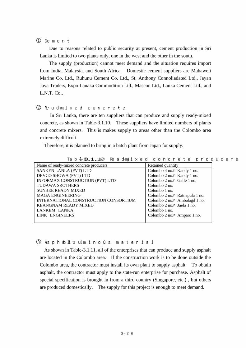
In Sri Lanka, there are ten suppliers that can produce and supply ready-mixed concrete, as shown in Table-3.1.10. These suppliers have limited numbers of plants and concrete mixers. This is makes supply to areas other than the Colombo area extremely difficult.
Therefore, it is planned to bring in a batch plant from Japan for supply.
Table-3.1.10 Ready-mixed concrete producers Name of ready-mixed concrete producers Retained quantity SANKEN LANLA (PVT) LTD DEVCO SHOWA (PVT) LTD INFORMAX CONSTRUCTION (PVT) LTD TUDAWA SROTHERS SUNBEE READY MIXED MAGA ENGINEERING INTERNATIONAL CONSTRUCTION CONSORTIUM KEANGNAM READY MIXED LANKEM LANKA LINK ENGINEERS
Colombo 4 no.、 Kandy 1 no. Colombo 2 no.、 Kandy 1 no. Colombo 2 no.、 Galle 1 no. Colombo 2 no. Colombo 1 no. Colombo 2 no.、 Ratnapula 1 no. Colombo 2 no.、 Ambalagd 1 no. Colombo 2 no.、 Jaela 1 no. Colombo 1 no. Colombo 2 no.、 Amparo 1 no.
③ Asphalt (bituminous material)
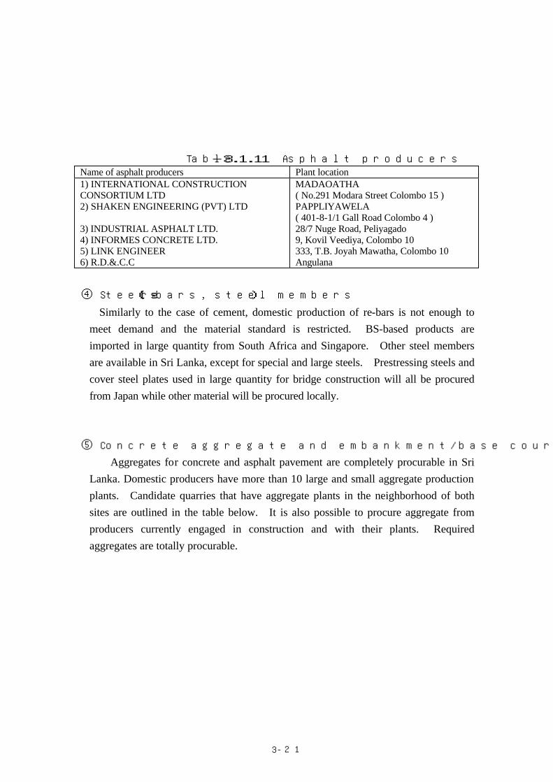
As shown in Table-3.1.11, all of the enterprises that can produce and supply asphalt are located in the Colombo area. If the construction work is to be done outside the Colombo area, the contractor must install its own plant to supply asphalt. To obtain asphalt, the contractor must apply to the state-run enterprise for purchase. Asphalt of special specification is brought in from a third country (Singapore, etc.) , but others are produced domestically. The supply for this project is enough to meet demand.
3-
21
Table-3.1.11 Asphalt producers Name of asphalt producers Plant location 1) INTERNATIONAL CONSTRUCTION CONSORTIUM LTD 2) SHAKEN ENGINEERING (PVT) LTD 3) INDUSTRIAL ASPHALT LTD. 4) INFORMES CONCRETE LTD. 5) LINK ENGINEER 6) R.D.&.C.C
MADAOATHA ( No.291 Modara Street Colombo 15 ) PAPPLIYAWELA ( 401-8-1/1 Gall Road Colombo 4 ) 28/7 Nuge Road, Peliyagado 9, Kovil Veediya, Colombo 10 333, T.B. Joyah Mawatha, Colombo 10 Angulana
④ Steels (re-bars, steel members)
Similarly to the case of cement, domestic production of re-bars is not enough to meet demand and the material standard is restricted. BS-based products are imported in large quantity from South Africa and Singapore. Other steel members are available in Sri Lanka, except for special and large steels. Prestressing steels and cover steel plates used in large quantity for bridge construction will all be procured from Japan while other material will be procured locally.
⑤ Concrete aggregate and embankment/base course materials for road
Aggregates for concrete and asphalt pavement are completely procurable in Sri Lanka. Domestic producers have more than 10 large and small aggregate production plants. Candidate quarries that have aggregate plants in the neighborhood of both sites are outlined in the table below. It is also possible to procure aggregate from producers currently engaged in construction and with their plants. Required aggregates are totally procurable.

3-
22
Table―3.1.12 Procurement of Aggregate and Embankment Materials
Mate
rial
Type
NO.93 Gampola Bridge No.239 Muwagama Bridge
Aggregate (concrete, asphalt paving)
Fine aggregate (sand)
① Mahaweli River sand
Judging from laboratory test results in
the ADB project, this is applicable as
fine aggregate for concrete.
① Kelani and Kalu Rivers sand
Since there is no place near Ratnapura
where fine aggregate can be quarried,
fine aggregate will be procured from
the suburb of Colombo.

3-
23
Coarse aggregates (crusher run)
①Near the Kotmalle dam ~
20km: The quarry where coarse aggregates were quarried at a time of Kotmalle dam construction. Two crushers are installed, with production enough for use during construction of this bridge. The rock quality is mainly metamorphic rock (gneiss) showing dark blue while including partially silicic and granitic rocks. Rock mass falls into Soft rock II to medium hard rock classes, but, as aggregate, may be considered to fall approximately in the medium hard rock class. Because of schistosity, the rock shows flat and planular shape when crushed. Judging from the rock type, rock quality, and application result for existing concrete structures and pavement, the material is applicable as aggregate for concrete and asphalt pavement in this project. ② A005 ~ 15km on the
NuwaraElya side: Because the rock quality here is approximately similar to that of the quarry of ①, the material can be applied to the project. However, due to lack of crushers, crushing is manual. As a result, the production is considered insufficient.
① A4~40km near Balangoda: Quarries are dotted around the location about 6 km south along the Class B road from Balangoda about 40 km east of Ratnapura. Quarried rocks are transported to the nearby (1 km) RC&DC asphalt plant (with one crusher) that produces crusher run. As rocks are brought in from several quarries, production is considered sufficient. The rock quality falls in Soft rock II to medium hard gneiss, with black dyke of biotite mass and white dyke of feldspar mass observed. The rock is mainly hard and stable, so that it is applicable as crusher run or aggregate. Note that a small amount of granite rock with high white feldspar content exists. This should be avoided during use because it is relatively fragile.

3-
24
Em
bankment m
aterials
① Route B154 ~ 3km near Peradenia: Cut slope on both sides at a distance of about 3 km from the existing Gampola Bridge. The soil here is sandy silt to silty soil and applicable as embankment material. In certain locations, however, extremely oxidized/weathered silty clay to clayey silty soil in reddish brown color is near the surface layer. This material is not considered appropriate for embankment material. ② Route B154 ~ 5km near Peradenia: RDA is currently quarrying the base course material from the cut slope on one side about 5 km from the existing Gampola Bridge. The soil is less weathered than the wall rock and contains a large amount of small quartz gravel, indicating silty sand with mixed sand gravel. Because mixing of gravel and its sandy characteristics, soil compaction is satisfactory, which is advantageous for application as embankment material.
① Near Ratnapura~5km The borrowing pit from which RDA is currently quarrying is not located near Ratnapura. Judging from the surrounding ground condition, quarrying of embankment material is possible. Candidate locations will be selected within a 5 km radius. The material is extremely oxidized/weathered silty clay to sandy soil in reddish brown color. Application to embankment material is considered possible. Before selection of the quarrying site, however, it is recommended to refer to the result of tests at the original location and in the laboratory.
⑥ Lumber
Lumber is completely available in Sri Lanka, except that the plywood for special forms and plywood 15 mm or more thick are completely not available. The quality is relatively satisfactory and thus fully applicable for bridge construction.
⑦ Other construction materials and equipment
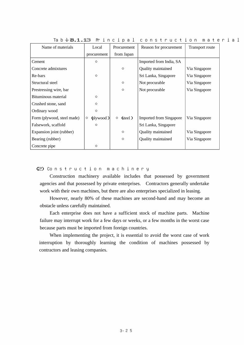
Bricks and roof tiles are supplied in sufficient quantity in Sri Lanka. All special materials, such as prestressing steel, etc. necessary for bridge construction must be imported. Supply sources of principal materials are shown in Table-3.1.13.
3-
25
Table-3.1.13 Principal construction material supply sources
Name of materials Local
procurement
Procurement
from Japan
Reason for procurement Transport route
Cement
Concrete admixtures
Re-bars
Structural steel
Prestressing wire, bar
Bituminous material
Crushed stone, sand
Ordinary wood
Form (plywood, steel made)
Falsework, scaffold
Expansion joint (rubber)
Bearing (rubber)
Concrete pipe
○
○
○
○
○
○(plywood)
○
○
○
○
○
○(steel)
○
○
Imported from India, SA
Quality maintained
Sri Lanka, Singapore
Not procurable
Not procurable
Imported from Singapore
Sri Lanka, Singapore
Quality maintained
Quality maintained
Via Singapore
Via Singapore
Via Singapore
Via Singapore
Via Singapore
Via Singapore
Via Singapore
(2) Construction machinery
Construction machinery available includes that possessed by government agencies and that possessed by private enterprises. Contractors generally undertake work with their own machines, but there are also enterprises specialized in leasing.
However, nearly 80% of these machines are second-hand and may become an obstacle unless carefully maintained.
Each enterprise does not have a sufficient stock of machine parts. Machine failure may interrupt work for a few days or weeks, or a few months in the worst case because parts must be imported from foreign countries.
When implementing the project, it is essential to avoid the worst case of work interruption by thoroughly learning the condition of machines possessed by contractors and leasing companies.
3-
26
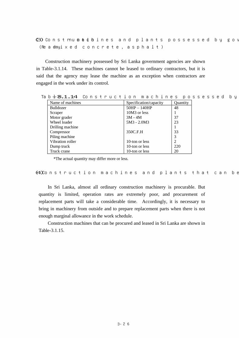
(3) Construction machines and plants possessed by government agencies
(Ready-mixed concrete, asphalt)
Construction machinery possessed by Sri Lanka government agencies are shown
in Table-3.1.14. These machines cannot be leased to ordinary contractors, but it is said that the agency may lease the machine as an exception when contractors are engaged in the work under its control.
Table-3.1.14 Construction machines possessed by government agency Name of machines Specification/capacity Quantity Bulldozer Scraper Motor grader Wheel loader Drilling machine Compressor Piling machine Vibration roller Dump truck Truck crane
50HP – 140HP 10M3 or less 3M - 4M 5M3 - 2.0M3 350C.F.H 10-ton or less 10-ton or less 10-ton or less
48 1 37 23 1 33 3 2 220 20
*The actual quantity may differ more or less.
(4)Construction machines and plants that can be procured or leased in Sri Lanka
In Sri Lanka, almost all ordinary construction machinery is procurable. But
quantity is limited, operation rates are extremely poor, and procurement of replacement parts will take a considerable time. Accordingly, it is necessary to bring in machinery from outside and to prepare replacement parts when there is not enough marginal allowance in the work schedule.
Construction machines that can be procured and leased in Sri Lanka are shown in Table-3.1.15.

3-
27
Table-3.1.15 List of construction machines procurable in Sri Lanka Name of construction machines Specification/capacity Quantity Backhoe 0.5m3 or less
0.5m3 - 1.0m3 1.1m3 - 1.5m3 1.5m3 or more
6 44
7 3
Bulldozer 50 H.P - 100 H.P 101 H.P - 139 H.P 140 H.P - 179 H.P 180 H.P - 250 H.P 251 H.P - 350 H.P 350 H.P or more
143 88 25 41 32 17
Motor grader 3.0m ( blade length ) 3.5m (blade length ) 4.5m (blade length )
13 67
6 Wheel loader 1.5m3 or less
1.5m3 - 2.0m3 2.0m3 - 2.5m3 2.5m3 or more
14 70 33 12
Backhoe with tires 1.0m3 or less 68 Compressor 175 C.F.M
175 – 350 C.F.M 350 C.F.M or more
40 42 13
Vibration roller 5ton or less 5ton - 10ton
8 10
Dump truck 5ton or less 5ton - 7ton 7ton - 10ton 10ton - 16ton 16ton or more
55 147 97
120 35
Asphalt plant 50ton/h or less 50ton/h or more
1 3
Distributor 1,000 liters 4,000 liters
19 4
Truck crane 10ton or less 10ton or more
2 24
Crawler crane 37ton 80ton
15 2
Stone crusher 20ton/h or less 20ton/h - 50ton/h 50ton/h - 100ton/h 100ton/h or more
1 30 11
4

3-
28
3)Construction machines whose procurement must be made outside of Sri Lanka
Special construction machines are extremely difficult to procure in Sri Lanka.
Machines necessary for smooth implementation that must be brought in from outside Sri Lank are listed in Table-3.1.16.
Table-3.1.16 Machines to be imported
Name of machines Specification/capacity
Crawler crane Vibro-hammer Generator Compressor Earth auger machine Reverse excavator Grouting machine Crawler drill
50 TON 90 KW, 60 KW 250 KVA 11 M3 1,000 M3 - 1,200 M3 S 320 φ1,000~φ3,000 38 MM, 50 MM 38 MM, 50 MM
4) Maintenance of construction machines
Machine maintenance is an extremely important factors governing the success of
a project. All raw materials (fuels and oils/greases) must be imported in Sri Lanka. Fuels
are supplied in sufficient quantity to meet demand. Since certain machines require special oils/greases, they may have to be imported beforehand after selection of the machine. Machine parts must be stocked at the site when using machinery of local contractors if it is to be controlled and used for a long period of time. Even for leased machines, it is necessary to stock parts beforehand after confirmation of machine model.
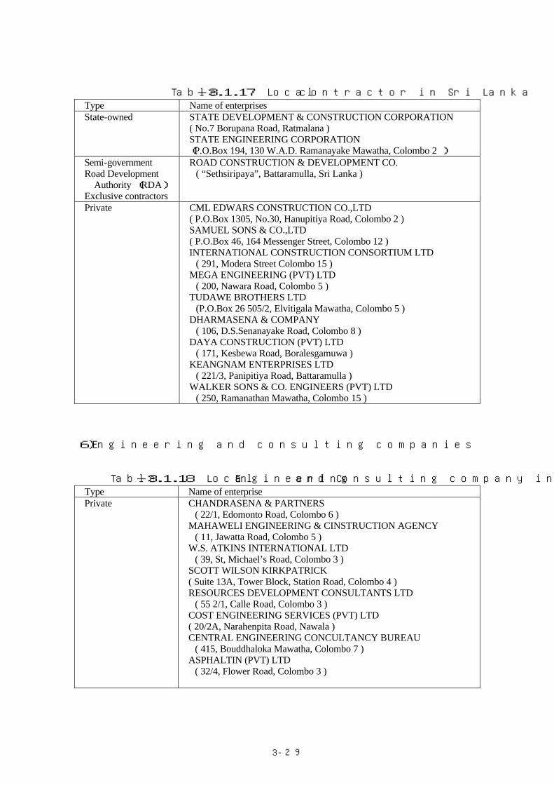
5) Local contractors
Enterprises to be engaged in bridge construction are either state-owned or private survey/research, design, and contractor companies. Enterprises listed in the table below are excellent ones registered in RDA.
3-
29
Table-3.1.17 Local contractor in Sri Lanka Type Name of enterprises State-owned STATE DEVELOPMENT & CONSTRUCTION CORPORATION
( No.7 Borupana Road, Ratmalana ) STATE ENGINEERING CORPORATION (P.O.Box 194, 130 W.A.D. Ramanayake Mawatha, Colombo 2 )
Semi-government Road Development
Authority (RDA) Exclusive contractors
ROAD CONSTRUCTION & DEVELOPMENT CO. ( “Sethsiripaya”, Battaramulla, Sri Lanka )
Private CML EDWARS CONSTRUCTION CO.,LTD ( P.O.Box 1305, No.30, Hanupitiya Road, Colombo 2 ) SAMUEL SONS & CO.,LTD ( P.O.Box 46, 164 Messenger Street, Colombo 12 ) INTERNATIONAL CONSTRUCTION CONSORTIUM LTD ( 291, Modera Street Colombo 15 ) MEGA ENGINEERING (PVT) LTD ( 200, Nawara Road, Colombo 5 ) TUDAWE BROTHERS LTD (P.O.Box 26 505/2, Elvitigala Mawatha, Colombo 5 ) DHARMASENA & COMPANY ( 106, D.S.Senanayake Road, Colombo 8 ) DAYA CONSTRUCTION (PVT) LTD ( 171, Kesbewa Road, Boralesgamuwa ) KEANGNAM ENTERPRISES LTD ( 221/3, Panipitiya Road, Battaramulla ) WALKER SONS & CO. ENGINEERS (PVT) LTD ( 250, Ramanathan Mawatha, Colombo 15 )
6)Engineering and consulting companies
Table-3.1.18 Local Engineering and Consulting company in Sri Lanka Type Name of enterprise Private CHANDRASENA & PARTNERS
( 22/1, Edomonto Road, Colombo 6 ) MAHAWELI ENGINEERING & CINSTRUCTION AGENCY ( 11, Jawatta Road, Colombo 5 ) W.S. ATKINS INTERNATIONAL LTD ( 39, St, Michael’s Road, Colombo 3 ) SCOTT WILSON KIRKPATRICK ( Suite 13A, Tower Block, Station Road, Colombo 4 ) RESOURCES DEVELOPMENT CONSULTANTS LTD ( 55 2/1, Calle Road, Colombo 3 ) COST ENGINEERING SERVICES (PVT) LTD ( 20/2A, Narahenpita Road, Nawala ) CENTRAL ENGINEERING CONCULTANCY BUREAU ( 415, Bouddhaloka Mawatha, Colombo 7 ) ASPHALTIN (PVT) LTD ( 32/4, Flower Road, Colombo 3 )

3-
30
7)Foreign contractors (India, Southeast Asian countries, Europe) making advance
into Sri Lanka
Table-3.1.19 shows foreign contractors currently active in Sri Lanka.
Table―3.1.19 Foreign contractors Name of contractors Address AF CONS(India) CHRISTIANI NIELSEN(UK) W.S.ATKINS (UK) LEMMIN KAINEN CONSTRUCTION LTD(Finland) KEANGNAM ENTERORISES LTD(Korea) SKANSKA INTERNATIONAL(UK) JILIN(China) SHANHAI ENGINEERING CONS.GROUP (India)
No.50/12 Sir James.Peiris Mawatha Col.2 No.190 Galle Road Col.3 No.39 St.Michale’s Road Col.3 No.64 Horton Place Col.7 No.221/3 Pannipitiya Road Battaramulla No.21A Balahenmulla Lane Col.6 No.7 Rorlshrue Place Off Col.10 No.127/3 Vije Kumaratnuge Mawatha Col.6
8)Japanese contractors in Sri Lanka
Table-3.1.20 shows Japanese contractors currently engaged in projects in Sri
Lanka.
Table -3.1.20 Japanese contractors Name of contractors Address Kajima Corporation Kumagai Gumi Co., Ltd. Taisei Corporation Hazama-Gumi Ltd. Mitsui Construction Co., Ltd. Penta-Ocean-Wakachiku joint venture
NO.481-C GALLERO. COLOMBO 3 2ND FLOOR NANDA INVESTMENTS BUILDING 25-2/1 C.W.W KANNANGARA MWT. COLOMBO 7 C/O COLOMBO HILTON HOTEL SQUARE LOYUS RD. COLOMBO 1 7TH FLOOR UNITY PLAZA BAMBALAPITIYA COLOMBO 4 295 MADAMPITIYA RD. COLOMBO 14 P.O.BOX 383 KOCHCHI-KADE GATE No.4 COLOMBO PORT COLOMBO 13
3-1-6 Implementation Schedule
This plan will be implemented as shown in the schedule below after conclusion
of the Exchange of Notes. 1)Implementation design
The detailed design will be conducted and design and bid documents prepared after
conclusion of the consulting agreement.

3-
31
2)Bidding and contractor agreement
The project agreement will be a direct one between the Sri Lanka Government
and the Japanese contractor. Selection of the Japanese contractor will be based on open tendering addressed to Japanese contractors.
Examination items will be discussed beforehand with JICA for approval, then prequalification of Japanese contractors will be made. A consulting company on behalf of the implementing agency of the Sri Lanka Government will handle prequalification.
Bid evaluation and selection of successful bidders will be conducted in the presence of Sri Lanka Governmental staff, consulting company, and bidders, and a witness representing JICA. The construction agreement will be concluded after bid evaluation and determination of successful bidders.
In parallel with conclusion of the construction agreement, the Sri Lanka Government will conclude the banking arrangement as soon as possible with a Japanese authorized foreign exchange bank in order to receive aid funds from the Japanese Government and to make payment to Japanese contractors. The banking arrangement is the basis on which the Sri Lanka Government will issue the Authorization to Pay (A/P) necessary for reception of aid funds from the Japanese Government and advance payment to contractors as well as for application to obtain an export license from MITI. This is also necessary to commence project implementation simultaneously with conclusion of the construction agreement.
Then, approval of the contract is necessary. Approval means that the Japanese Government verifies the appropriateness of the contract as an object of this grant aid. It is also a prerequisite for the contract to go into effect. Specifically, the Ministry of Foreign Affairs receives the contract from the Sri Lanka Government via overseas establishment, determining appropriateness for approval. The Japanese contractor will implement the contract after receiving the approved contract and authorization to pay (A/P).
3)Construction work
The construction work begins with preparation, followed by detouring work,
removal of existing bridges, bridge permanent works including substructure, superstructure (girders, bridge surface), approach road, and appurtenant works such as bank protection work, and ends with removal of materials and equipment related to the project. Around the site in Sri Lanka, periods from the middle of April to the

3-
32
middle of June and from October to November are major rainy seasons. During this period, substructure work is limited.
The implementation schedule of this project is shown in Table-3.1.21. .

3-33
Table-3.1.21 Implementation Schedule
1 2 3 4 5 6 7 8 9 10 11 12 13 14 15 16 17 18 19 20 21 22 23 24
Field Survey (Site)
Study in Japan (Japan)
MobilizationTemporary Bridge,Cofferdam
Foundation
SubstructureFabrication of PC Girder
Erection of PC Girder
Slab, Handrail
Approach Road
Pavement
Miscellaneous
Demobilization
No.93 Gampola Bridge
No.239 Muwagama Bridge
Detailed D
esignP
rocurement and C
onstruction
7.5 months
24.0 month

3-
34
3-1-7 Obligations of recipient country
During implementation of this plan, the Sri Lanka Government will be
responsible for implementing the following matters. 1)Acquisition of land
(1)Securing of the land and transfer/removal of buildings (school, houses, shops) in the land
Table-3.1.3 shows the facility occupation area for replacement of Gampola and Muwagama Bridges. The land within this occupation area is secured for occupation of project facilities, and existing buildings are to be secured and removed at the same time.
(2)Securing of the work yard. (Permanent and temporary facilities)
The proposed yard occupation area in the temporary facility plan for Gampola and Muwagama Bridges is shown in Table-3.1.5. The land within this occupation area is secured for occupation of facilities of this project, and existing buildings are to be secured and removed at the same time.
2)Removal of existing bridges
① Gampola Bridge
a) Time of removal:To secure traffic during implementation period, the existing bridge shall be removed according to the implementation plan after completion of the new bridge. Early removal of the bridge is necessary because of safety concerns due to decrease in the depth of embedment of central piers of the existing bridge.
b) Scope of removal:The superstructure and central piers will be removed. Abutment should not be removed because it will not affect the river flow and function rather as a revetment even after completion of the new bridge.
② Muwagama Bridge
a) Time of removal:To secure the traffic during implementation period, the existing bridge shall be removed according to the implementation plan after

3-
35
completion of the new bridge. Early removal of the bridge is necessary because this is located on the upstream side of the new bridge and because of concern regarding the stability due to decrease in the depth of embedment of central piers of existing bridge.
b) Scope of removal:The superstructure and central piers shall be removed. The abutment should not be removed because it will not affect the river flow and will function as a revetment even after completion of the new bridge.
3)Transfer of utilities
The power transmission line, telephone line, and water pipeline will be transferred at the cost of Sri Lanka counterpart. For transfer items and costs, refer to Table-3.1.4. In particular, the high-voltage 11 kV line provided on the upstream side of Gampola Bridge must be removed before commencement of the project.
4)Tax benefits
All project-related Sri Lanka taxes will be exempted. The legal procedure in Sri Lanka for tax exemption will be made by the Sri Lanka counterpart.

3- 36
3-2 Operation and Maintenance Method
Upon completion of the project, RAD will operate and maintain the rehabilitated bridge. 1) Maintenance method
For effective utilization of RDA’s limited available funds, the maintenance
method mainly comprising daily and periodic inspections will be employed to ensure early detection of damage and early countermeasures, thereby preventing major damage to the bridge main body and accessories, such as scouring of abutments by river water, collapse of river embankments, collapse of slopes, etc. ① Daily inspection
Two inspection vehicles will be used for inspections of the route concerned about once a month for visual appearance inspection of the road surface, shoulder, and slope. The condition will be recorded in the form of records to be delivered to the engineer. The inspection crew will consist of three persons per vehicle, including an inspector, recorder, and driver.
② Periodic inspections
When the river water level has lowered after the rainy season, periodic inspection will be made of the river embankment, river bed protection state, and river bed scouring condition. The inspector will survey the damage condition and establish a repair plan.
On the basis of these inspection results, the engineer will judge the necessity of
repairs and implement repairs early to prevent worsening.
2) Maintenance and operation method
In order to implement the maintenance method described in 1) above, it is
necessary to proceed with planning by the maintenance organization in the RDA. ① A daily inspection group will be established in the RDA. The group members are as follows:
・Engineers :2 (1 persons×2 shifts)
・Inspector, recorder, driver :6 (3 persons×2 shifts)
・Inspection vehicles :2 (1 person ×2 shifts)
・Record maintenance person :1

3- 37
② A repair group will also be established, to rapidly meet the needs for minor repairs indicated by the daily inspections.
③ A maintenance manual will be developed for planned training of inspectors and recorders by the dispatched specialist.
④ The daily inspection records will be entered into a data base to facilitate appropriate estimation of the required maintenance costs.
⑤ Drawings of the project will be stored for future rehabilitation work. 3) Maintenance and operation costs
The content and costs of maintenance estimated for the ten years after completion of the project are as shown in Table-3.2.1.
Table―3.2.1 Content and cost of maintenance .
Period Content Cost (1000Rs.)
① Slope repair ② Revetment repair ③ River bed repair ④ Pavement repair (patching)
1,212 ㎡ x 5 Rs = 6.1
342 ㎡ x 350 Rs x 5% = 6.0 630 ㎡ x 1,750 Rs x 5% = 55.1
2,740 ㎡ x 400 Rs x 5% = 54.8
Yearly
Sub total 122(1,000Rs./year)
①Bridge surface repair ②Medium repair of riverbed ③Medium repair of embankment
④Pavement overlay
2,128 ㎡ x 400 Rs = 851.2 342 ㎡ x 350 Rs x 10% = 12.0
630 ㎡ x 1,750 Rs x 10% = 110.2 2,740 ㎡ x 400 Rs = 1,096.0
Every five years
Sub total 2,069(1,000Rs./year)
①Steel bridge repainting 8,733m2 x 310 Rs = 2,707.2 Every ten years 2,707 (1,000Rs./year)
Costs for ten-year period 8,605 (1,000Rs./year)
Expenses necessary for maintenance costs are estimated as follows: 8065.0 (1,000 Rs/10 years) ≒ 807(0.8 million Rs/1 year)
The percentage of above maintenance costs(0.8 million Rs/year)in the existing
maintenance costs (1,416 million Rs/year) is about 0.06%. As a percentage of the existing RDA budget(9,720 millon Rs/year)it is about 0.008%.

1-1
Chapter 1 Background of the Project
In Sri Lanka, the development of an inland transportation network for the transport of
agricultural products accompanied the growth of plantation farming. In recent years, the
preferred means of inland transport means has shifted from railways to roads. By 1995,
roads were relied on for about 95% of freight and 85% of passenger transportation. Road
traffic is indispensable not only for economic activities, but also for civil life, and the traffic
volume is increasing year by year. Nevertheless, development of the roads is lagging behind
the increase in traffic volume. In this context, assurance of the safety of road traffic and
strengthening traffic capacity are considered to be issues that Sri Lanka must address.
The total length of road networks in Sri Lanka is about 100,000 km, in which the length
of trunk national highways (for Classes A and B) remains only about 11,000 km. Though
most national highways are paved, various facilities are substantially outdated. The Sri
Lanka Government places its priority on measures for rehabilitation and control of existing
facilities while relying on grant aid from foreign countries.
It is also proceeding with development of principal road networks through the improvement
and expansion of capacity of trunk lines and the construction of new lines.
Bridges in Sri Lanka are heavily deteriorated. Among the more than 4,000 bridges all
over the country, 200 to 300 are reported to require rehabilitation. However, due to
restrictions in terms of budget and technology, only 20% have been rehabilitated. The
remaining bridges continue to be used in spite of the growing danger of collapse caused by
substantial damages. In addition, many bridges can not cope with the growing traffic
demand because of their narrow width. Since these bridges are used in the daily life of local
residents and are thus highly needed as social infrastructure, their rehabilitation is necessary
In the light of the above circumstances, the Sri Lanka Government (competent ministry:
Ministry of Transport and Highways, project implementing agency: Road Development
Authority, RDA) requested in 1990 that the Japanese Government develop M/P related to the
National Bridge Rehabilitation Plan. In response, the Japanese Government conducted a
Project Formation Study on roads and bridges from February to March 1993 and carried out a

1-2
Development Study, the National Bridge Rehabilitation Plan, from March 1995 to July 1996.
Subsequently, in May 1997, on the basis of these study results, the Sri Lanka Government
requested the Japanese Government to provide assistance for rehabilitation, through grant-aid,
for 13 bridges among 35 top-priority bridges (requiring rehabilitation by the year 2000)
selected from 100 bridges covered by the above development study. The Japanese
Government dispatched a preliminary study team to Sri Lanka in November 1997, which
selected five bridges to be surveyed. In March 1998, a full-scale study was implemented.
Rehabilitation was completed on three of the five bridges concerned, and will be completed
for the two remaining bridges in March 2001.
The Sri Lanka Government, which intends to promote rehabilitation of other bridges,
sent a request to the Japanese Government in August 1998, concerning implementation of
rehabilitation of 19 bridges under the secondary grant aid project. In response to the request,
the Japanese Government, dispatched the Basic Design study team to the site (the first field
survey) in June 2000, conducting survey of requested bridges, discussions with the Sri Lanka
Government, and analysis of data and coordination with authorities concerned in Japan. In
consequence, two bridges of Gampola and Muwagama were selected to be covered by this
project in view of their urgent need of rehabilitation and socio-economic contributions. In
July 2000, a study (the second field survey) was started.
This Project consists of reconstruction of the Gampola Bridge to eliminate a bottleneck
on Route A5, a critical route in Sri Lanka, assuring a safe and smooth traffic flow while
contributing to the development of the economy of Sri Lanka as well as regional societies
around the bridge. The Project also includes reconstruction of the Muwagama Bridge,
which has been an obstacle to traffic in the rapidly developing Ratnapura City and suburban
Muwagama area. This work will assure safe and smooth traffic flow while contributing to
the development of economy of Sri Lanka as well as regional societies in the area around the
bridge.

CHAPTER 2

2- 1
Chapter2 Contents of the Project
2-1 Objectives of the Project
In Sri Lanka, the preferred means of inland transport has shifted from railways to roads in
recent years. Roads are relied on for about 95% of freight and 85% of passenger transportation. In the face of a rapid increase in traffic volume, road traffic has become indispensable for economic activities and for civil life. Assurance of the safety of road traffic and strengthening traffic capacity are considered to be issues that Sri Lanka must address.
Though most national highways are paved, various facilities are substantially outdated. The Sri Lanka Government places a priority on measures for rehabilitation and management of existing facilities while relying on grant aid from foreign countries. It is also proceeding with development of principal road networks through the improvement and expansion of capacity of trunk lines and the construction of new lines.
Bridges in Sri Lanka are badly deteriorated. Among the more than 4,000 bridges all over
the country, 200 to 300 are reported to require rehabilitation. However, due to restrictions in terms of budget and technology, only 20% have been rehabilitated. In addition, many bridges cannot cope with the growing traffic demand because of their narrow width. Since these bridges are used in the daily life of local residents and are thus highly needed as social infrastructure, their rehabilitation is necessary.
The Japanese Government conducted a Project Formation Study on roads and bridges in
1993 and carried out a Development Study, the National Bridge Rehabilitation Plan, from March 1995 to July 1996. In the course of the development study, a list of bridges that were deteriorated and required to be rehabilitated to ensure the safety while coping with increase in the traffic demand was established. Subsequently, on the basis of the study results, the Sri Lanka Government requested the Japanese Government to provide assistance for rehabilitation, through grant-aid, for 13 bridges among 35 top-priority bridges (requiring rehabilitation by the year 2000) selected from 100 bridges covered by the above development study. After selection of five bridges to be surveyed, in March 1998, a full-scale study was implemented. Rehabilitation of three of the five bridges concerned was completed in March 2000, and rehabilitation of the two remaining bridges will be completed in March 2001.
The Sri Lanka Government, which intends to promote rehabilitation of other bridges, sent a
request to the Japanese Government in August 1998 concerning implementation of rehabilitation of 19 bridges under a secondary grant aid project. In response to the request,

2- 2
the Japanese Government dispatched the Basic Design study team to the site (for the first field survey) in June 2000 to survey the requested bridges, to hold discussions with the Sri Lanka Government, analyze data, and coordinate matters with authorities concerned in Japan. In consequence, two bridges of Gampola and Muwagama were selected to be covered by this project in view of the urgent need of rehabilitation and socio-economic contributions. In July 2000, a study (for the second field survey) was started.
This Project consists of reconstruction of the Gampola Bridge to eliminate a bottleneck on
Route A5, a critical route in Sri Lanka, to assure a safe and smooth traffic flow while contributing to the development of the economy of Sri Lanka as well as regional communities around the bridge. The Project also includes reconstruction of the Muwagama Bridge, which has been an obstacle to traffic in the rapidly developing Ratnapura City and suburban Muwagama area. This work will assure a safe and smooth traffic flow while contributing to the development of economy of Sri Lanka as well as regional communities in the area around the bridge.

2- 3
2-2 Basic Concept of the Project 2-2-1 Selection of bridges to be surveyed 1) Basic policy for selection
In this plan, the 19 bridges shown in Table–2.2.1 were included in the request from the Sri Lanka Government.
Table-2.2.1 List of 19 bridges to be surveyed No. RDA Sr No. Route Bridge site Bridge type 1 No.7 B425 Gampaha, Western
Province L=139.2, W=6.85, PSC
2 No.22 B431 Kandy, Central Province
L=162.3, W=4.17, Bailey
3 No.42 B464 Hambantota, Southern Province
L= 59.2, W=4.29, RSJ/RCS
4 No.59 B157 Kalutara, Western Province
L= 51.0, W=3.82, RSJ/RCS
5 No.66 B111 Gampaha, Western Province
L= 36.8, W=6.40, ST.TR.H
6 No.67 B157 Kalutara, Western Province
L= 19.1, W=3.50, RSJ/RCS
7 No.93 AA005 Kandy, Central Province
L= 98.3, W=4.85, ST.TR
8 No.122 B045 Chilaw, North Western Province
L= 18.5, W=5.00, RSJ
9 No.130 B127 Kegalle, Sabaragamuwa Province
L= 24.7, W=4.54, ST.TR
10 No.154 B445 Kegalle, Sabaragamuwa Province
L= 10.4, W=4.60, RSJ/BUC
11 No.157 B461 Matale, Central Province
L= 24.8, W=3.20, RSJ/BUC
12 No.158 B473 Chilaw North Western Province
L= 19.7, W=5.20, ST.TR
13 No.181 B312 Matale, Central Province
L= 18.9, W=3.80, RSJ/RCS
14 No.197 B288 Gampaha, North Western Province
L= 52.8, W=5.48, ST.TR.
15 No.200 B478 Kurunegala, North Western Province
L= 78.6, W=4.25, ST.TR/H
16 No.239 B390 Ratnapura, Sabaragamuwa Province
L=107.0, W=4.30, ST.TR/H
17 No.267 B458 Kalutara, Western Province
L= 18.7, W=5.27, ST.TR/H
18 No.272 B216 Kalutara, Western Province
L= 19.4, W=5.20, RCC
19 No.273 B458 Kalutara, Western Province
L= 26.4, W=4.25, ST.TR/H

2- 4
Selection was made in the first field study according to the procedure shown in
Fig.2.2.1. Criteria for selection were as follows: ① Existence of any project
Bridges for which a project is already under way or for which a project plan is established were excluded.
② Ensuring safety during implementation of the project
Bridges for which there exist problems in terms of public order, survey, and project implementation were excluded.
③ Technical capacity of the counterpart to implement the project
Since it was confirmed that the Sri Lankan counterpart can implement independently work for bridges up to a length of about 20 m, bridges with a length of 20 m or less were excluded.
④ Traffic volume
Because of common recognition with the Sri Lankan counterpart that the traffic volume is the most appropriate method to quantitatively judge the socioeconomic situation, grouping was made on the basis of traffic volume. As the field survey indicated that congestion occurs most frequently when the traffic volume exceeds 5000 vehicles/day, bridges to be rehabilitated were selected on the basis of whether or not the traffic volume there was 5000 vehicles/day. (See Fig.-2.2.1)
Bridges that were excluded from the final consideration because their length was
20 m or less were also considered during selection if the traffic volume there is large.
⑤ Overall evaluation Agreement with the Sri Lankan counterpart was reached as follows. Namely,
concerning bridges selected as described above, effects related to (a) consistency with the development plan, (b) present condition of bridges including the damage situation, (c) socioeconomic positioning, (d) traffic volume, and (e) technology transfer are rearranged and analyzed according to the statistical method to objectively determine priority for final selection of bridges to be rehabilitated.

2-5
Figure:-2.2.1 Flowchart of the Selection of the Proposed Bridges
YES NO
Exclude from undertaking
Exclude from undertaking
YES
Undertaking for Second Stage
Sri Lanka has a plan to undertake rehabilitation by other fund or his own budget among proposed 19 bridges.
There are some places, where it has concern security among proposed bridges.
Sri Lanka has possibility to undertakerehabilitation by his own technical methodand fund among proposed bridges.
According to the record, RDA constructed 20m class span bridges by his own technicalmethod and fund.
Exclude from undertaking
YES
NO 11 Bridges
NO
Prioritize by AHP method (Analytic Hierarchy Process).
Select bridges for appropriate project scalesin accordance with priority.
8 Bridges No.7, No.22, No.59, No.130, No.197, No.272, No.273, No.267
0 Bridge
11 Bridges
There are some places, where it has few traffic volumes among proposed bridges.
5 Bridges No.67, No.122, No.154, No.158, No.181
YES
4 Bridges No.67, No.122, No.154, No.181 NO
1 Bridge No.158
6 Bridges No.42, No.66, No.93, No.157, No.200, No.239
Priority List First Category by the result of traffic volume survey No.66, No.93, No.158, No.239 Second Category by the result of traffic volume survey No.42, No.157, No.200
The Proposed 19 bridges for the Study
2-6
2) Determination of priority among bridges under survey
Bridge selection for the grant-aid project must be made not only on the basis of traffic volume, but also on the basis of the degree of damage of existing bridges, and effects on the development plan and socio-economic condition.
Since these evaluation criteria cannot directly ensure quantitative evaluation, prioritization of bridges is not objective and remains vague. Therefore, this chapter includes a study made according to the Analytic Hierarchy Process (AHP) of seven bridges selected to determine priority among them.
(1) Outline of the Analytic Hierarchy Process (AHP)
The Analytic Hierarchy Process (AHP) features hierarchical structurization of a multi-purpose decision-making problem in terms of overall objective – evaluation criteria (comparative item or element) – alternative relationship. Even when decision-making must rely on experience and instinct, image, etc., this method can select an alternative through conversion into the qualitatively meaningful numerical values by weighing based on a pair comparison between evaluation criteria. Namely, this method is effective as a method to convert various concepts based on different ways of thinking and criteria, into one mass weight. Basically, AHP consists of the following three stages.
① First stage:Hierarchical structurization of a problem
A problem under complicated circumstances is decomposed into hierarchical structures. The top layer of the hierarchy consists of one element that is an overall objective (goal). For lower levels, several elements are determined from the relationship with the level immediately above in compliance with the subjective judgment of the decision-maker. The alternative comes at the bottom of this hierarchy.
② Second stage:Pair comparison of elements
Weighing is made among elements of each level. Namely, pair comparison between elements on one level is made with reference to a relationship element of a level immediately above. When n is assumed to be a prime number for comparison, the decision-maker will perform pair comparison of n(n-1)/2 pieces. Besides, using a
scale of importance, values used in pair comparison are determined to be

2-7
1/9,1/8,・・・・・,1/2,1,2,・・・・・,8,9. The content of individual numerical figures is shown in
the table below.
Scale of importance
Definition
1 Equal importance
3 Weak importance
5 Strong importance
7 Very strong importance
9 Absolute importance
(2,4,6, and 8 are to be used for respective intermediate levels.
A fraction is used when the level of importance is low.)
③ Third stage: Calculation of the priority
From the pair comparison matrix (known) obtained above, the weight (unknown) between elements in each level is calculated. A geometric average is used for calculation of the weight between elements.
Using the result of the weighing calculation between elements of each level, weighing of the layer as a whole is calculated. In this way, the priority of each alternative relative to the target is determined.
(2) Bridges concerned and evaluation items
① Bridges covered by hierarchical analysis
Hierarchical analysis is made for seven bridges (shown below) of Categories 1 and 2 determined in Table-2.2.2, Selection of Bridges Under Survey.
Table- 2.2.2 Bridges covered by hierarchical analysis
Serial No. Name
of route
Name of area
Bridge type
Bridge length and width
Traffic volume determined in
this survey
( ): Pedestrians
42 B-464 Hambantota, Southern Province
Three-span steel truss girder structure
L=59.2 W=4.29 3,374
(288)

2-8
66 B-111 Gampaha, Western Province
Two-span steel truss girder structure
L=36.8 W=6.40 8,165
(987)
93 AA-00
5
Kandy, Central
Province
Two-span steel truss girder structure
L=98.3 W=4.85 6,555
(6,434)
157 B-461 Matale, Central
Province
Three-span steel I-girder section
structure L=24.8 W=3.20
471
(215)
158 B-473
Chilaw, North
Western Province
Simple girder steel truss girder structure
L=19.7 W=5.20 6,081
(105)
200 B-478
Kurunegala,
North
Western
Province
Three-span steel truss girder structure
L=78.6 W=4.25 972
(66)
239 B-390 Ratnapura,
Sabaragamuwa Province
Three-span steel truss girder structure
L=107.0 W=4.30 8,209
(4,645)
② Evaluation items in the hierarchical analysis(Evaluation criteria)
The evaluation criteria for hierarchical analysis of bridges concerned are described below:
(a) Consistency with the development plan(Development plan)
Bridge selection must be made after study of the relationship between the development plan of Sri Lanka and bridges concerned while considering the importance of the development plan and the effect on the development plan.
(b) Resent condition of bridges including the damage situation(Existing bridge condition)
Bridge selection must be made while considering results of the bridge damage survey, structural standard (width, etc.), and the year of construction.
(c) Socioeconomic effects on Sri Lanka(Socioeconomic effects)
Evaluation must be made while considering the importance of the route, geological conditions, effects on the development plan, and industries.
(d) Socioeconomic effects on the area surrounding the bridge(Regional socioeconomic
effects)
Evaluation must be made of the effects on activation or infrastructure development of the regional society, such as schools, markets, hospitals, and police offices.

2-9
(e) Traffic volume (Traffic volume)
Evaluation must be made on the traffic volume (up/down total) in this study.
(f) Technology transfer effects(Technology transfer)
Considering the present condition of construction technology of Sri Lanka, the effects when bridge rehabilitation is to be covered by grant aid must be evaluated.
(3) Study of the priority order among bridges covered by the hierarchical analysis
① First stage:Hierarchical structurization of a problem
Comparison items (elements) for selection of bridges to be covered by grant aid are the working expenses, workability, environmental impact, and investment effects.
Target
Elements
Alternative
Fig.-2.2.2 Comparative elements for hierarchical analysis
② Second stage:Pair comparison of elements
In this stage, a pair comparison is made for each comparison item (element). The comparison results are shown in the table below. For weighing of pair comparison between elements, implementation and averaging of comment hearing through questionnaire, etc. will enable reflection of various concepts differing ways of thinking, standards, and thought. In this stage, it was decided to collect comments through
Bridges covered by grant aid
Dev
elop
me
nt
plan
Exi
stin
g br
idge
Soc
ioec
ono
mic
eff
ects
Reg
ion
al
soci
oeco
n
Tra
ffic
vo
lum
e
Tec
hn
olog
y tr
ansf
er
No.42
No.66 No.93 No.157 No.158 No.200 No.239

2-10
questionnaires from Sri Lanka side and member of study team and to use the result of the questionnaire. Table –3.2.3 shows the weight of pair comparison.
Table-2.2.3 Weight of pair comparison
Development plan
Existing bridge
condition
Socioeconomic effects
Regional socioeconomic
effects
Traffic volume
Technology transfer
Development plan 1 1/7 1/3 1/2 1/5 3
Existing bridge condition 7 1 6 4 4 7
Socioeconomic effects 3 1/6 1 1/2 1/3 4
Regional socioeconomic
effects 2 1/4 2 1 1/3 4
Traffic volume 5 1/4 3 3 1 7
Technology transfer 1/3 1/7 1/4 1/4 1/7 1
③ Third stage:Calculation of the priority
The priority is calculated by taking the geometric average of pair comparison results between elements. The calculation result is shown in Table-2.2.4.
Table-2.2.4 Priority of elements (1)
Calculation of geometric average Priority of elements
Development plan (1×1/7×1/3×1/2×1/5×3)^(1/6) 0.493 0.493/8.812=0.056
Existing bridge condition (7×1×6×4×4×7)^(1/6) 4.093 4.093/8.812=0.465
Socioeconomic effects (3×1/6×1×1/2×1/5×4)^(1/6) 0.833 0.833/8.812=0.094
Regional socioeconomic
results (2×1/4×2×1×1/3×4)^(1/6) 1.049 1.049/8.812=0.119
Traffic volume (5×1/4×3×3×1×7)^(1/6) 2.070 2.070/8.812=0.235
Technology transfer (1/3×1/7×1/4×1/4×1/7×1)^(1/6) 0.274 0.274/8.812=0.031
Total 8.812 1.000

2-11
Then, the score (any score classification will be acceptable) is determined for each element of each alternative. The score is multiplied by the weight of each element for overall evaluation of each route. The score of each element is shown in Table-2.2.5 for each alternative. Score allocation is as shown in the table below.
Table-2.2.5 Priority of elements (2)
Element Classification Score
Development plan
Related development plan exists and is either completed or in progress
Related development scheduled for the near future
Development plan in progress near the bridge site
Development plan scheduled for completed in the near future near the site
The plan exists near the bridge site, but not clear.
5
4
3
2
1
Existing bridge condition
Repair or replacement needed immediately
Old bridge, which must be replaced in the near future and whose width is small.
Though narrow in width, the bridge shows no remarkable damage but must be watched with care.
Wide bridge that requires simple touch-up of paint, etc.
No problem in terms of the width, state, etc.
5
4
3
2
1
Socioeconomic effects
With definite grounds for selection, bridge rehabilitation will bring about the effect within a short period.
Though definite grounds exist for selection, bridge rehabilitation will require a certain time period to demonstrate its effectiveness.
Possibly effective in the future
5
3
1
Regional socioeconomic
effects
With definite ground for selection, the bridge rehabilitation will bring about the effect within a short period.
Though definite ground exists for selection, the bridge rehabilitation requires a certain time period to demonstrate its effectiveness.
Possibly effective in the future
5
3
1
Traffic volume
7000 vehicles/day or more
5000 vehicles/day or more to 7000 vehicles/day
3000 vehicles/day or more to 5000 vehicles/day
1000 vehicles/day ~3000 vehicles/day less than 1000 vehicles/day
5
4
3
2
1
Technology transfer
This type of work is rather rare in Sri Lanka and will prove highly effective.
A few examples of this type of work exist in Sri Lanka and will prove effective.
Sri Lanka has its own experience in this type of work will prove less effective.
5
3
1

2-12
Table-2.2.6 Ranking of alternatives
Development plan
Existing bridge
condition
Socioeconomic effects
Regional socioeconomic
effects
Traffic volume
Technology transfer
No.42 3 4 1 1 3 3
No.66 2 4 3 5 5 1
No.93 5 4 5 5 4 5
No.157 1 3 1 2 1 1
No.158 1 4 1 4 4 1
No.200 1 3 1 3 1 3
No.239 3 4 4 5 5 3

2-13
The score is multiplied by the weight of each element for overall evaluation of each route. It may be judged that the alternative route with the largest total sum has the highest priority. The result is shown in Table-2.2.7.
Table-2.2.7 Calculation of the priority order
No. Calculation of the priority order Priority order
No.42 3×0.056+4×0.465+1×0.094+1×0.119+3×0.235+3×0.031=3.04 5
No.66 2×0.056+4×0.465+3×0.094+5×0.119+5×0.235+1×0.031=4.05 3
No.93 5×0.056+4×0.465+5×0.094+5×0.119+4×0.235+5×0.031=4.30 1
No.157 1×0.056+3×0.465+1×0.094+2×0.119+1×0.235+1×0.031=2.05 7
No.158 1×0.056+4×0.465+1×0.094+4×0.119+4×0.235+1×0.031=3.46 4
No.200 1×0.056+3×0.465+1×0.094+3×0.119+1×0.235+3×0.031=2.23 6
No.239 3×0.056+4×0.465+4×0.094+5×0.119+5×0.235+3×0.031=4.27 2
As a result the priority order of the bridge is as follows’ First:No. 93, Second:No. 239, Third:No. 66, Fourth:No. 158, Fifth:No. 42
3)Selection of bridges to be rehabilitated
This project is expected to be of a scale nearly equivalent to the First Medium and Small Bridge Rehabilitation Project (Phase 1) (Sri Lanka Five-bridge Reconstruction Project). The expected bridge area of the first(No.93)and the second (No.239) bridges are beyond the
scale of Phase 1, so that implementation of the project for two bridges of No.93 and No.239 on the basis of grant-aid is considered appropriate.

2-14
Table-2.2.8 Comparison of the First Medium to Small Bridge
Rehabilitation Project (Phase 1) and this project in terms of bridge size
Serial NO. Bridge
length (m)
Width (m)
(Roadway)
Total
(m2)
Serial NO. Existing
bridge
length (m)
Estimated
width
(m2)
(Roadway)
Total
(m2)
NO.31 14.0 7.4 103.6 NO.93 98.3 7.4 727.4
NO.32 14.0 7.4 103.6 NO.239 107.0 7.4 791.8
NO.33 75.0 7.4 555.0 ― ― ― ―
NO.38 25.0 3.7 92.5 ― ― ― ―
NO.70 42.0 7.4 310.8 ― ― ― ―
Total 170.0 ― 1165.5 計 205.3 ― 1519.2
As the total of expected bridge area of the first(No.93)and the second (No.239) bridges is
beyond the scale of Phase 1, implementation of No.93 and No.239 was recommended as appropriate for implementation of the project.
The result of analysis conducted in Japan as described above was explained to the Sri Lankan counterpart before start of the second field survey. Agreement with the Sri Lankan counterpart was reached to the effect that the project will be implemented on two bridges only, namely, the first No. 93 (Gampola Bridge) and second No. 239 (Muwagama Bridge). Agreement was also reached among persons concerned that bridges ranked third and lower will not be brought forward.

2-
15
2-2-2 Rehabilitation plan policy
1)Outline of the bridge to be surveyed
(1) Site condition of bridges to be surveyed
① Gampola Bridge
This is located along the critical route A5 connecting Kandy, the second largest city in Sri Lanka, and Nuwara Eliya, a famous tourist resort, crossing Mahaweli River, the longest river of Sri Lanka, at Gampola. On the Kandy side of the bridge, the route passes through Gampola City, and B132 branches from this route toward Nawalapitiya. For the Kandy-Gampola section where the traffic volume is the largest in Route A5, improvement is under way under ADB aid. The improvement project is also scheduled for the mountainous road between Gampola and Nuwara Eliya under JBIC aid.
This bridge is the only one that connects Gampola City and the area on the opposite bank where there are public facilities such as a teacher training center, offices of the provincial government, and theaters. This is not only a bridge on a Class A national highway, but also plays an important role in the economy and social life of areas in the neighborhood of Gampola City.
The existing bridge was completed in 1926 and is 74 years old. Rehabilitation is required urgently because of functional degradation and problems related to traffic safety due to damage caused by wear and tear and increased traffic.
② Muwagama Bridge
This is a bridge located at an intersection of Route B369 branching from the national highway Route A4 in the middle of Ratnapura with the Kalu River, connecting Ratnapura City with the Muwagama area on the opposite side of the Kalu River. Ratnapura City is a famous jewel production site in Sri Lanka, has achieved rapid development in these years. In line with Ratnapura City, the Muwagama area is increasingly urbanized with a large number of houses and governmental buildings and schools located along Route B369. In the area about 10 km along Route B369, there are expanding tea and coconut plantations. In this situation, the bridge serves not only as a spine of traffic within the city, but also as a transport road for agricultural products.
For the national highway Route A4, the improvement project under Korean aid has been
completed for the 100 km section from Colombo to Ratnapura. Improvement is about to be started also for the section from Ratnapura toBalangoda.

2-16
The existing bridge was completed in 1920 and is 80 years old. Rehabilitation is urgently required because of functional degradation and problems related to traffic safety due to damage caused by wear and tear and increased traffic.
(2) Outline and damage condition of bridges to be surveyed
Table-2.2.9 shows an outline and damage condition of bridges to be surveyed. For both bridges, the soundness confirmation based on numerical analysis was not done because of lack of design calculation. As overall drawings and a general view of the substructure were stored, the soundness was evaluated visually using these drawings.

2-17
Table-2-2-9 Outline and damage condition of bridges to be surveyed
Bridge name Gampola Bridge(No.93) Muwagama Bridge(No.239) Bridge type Double simple-steel truss bridge Triple simple-steel truss bridge Bridge length 49.10m+48.90m=98.3m 20.00m+55.70m+20.00m=95.7m
Roadway 4.85m 4.25m Width Sidewalk [email protected] 2@1.20m
Skew angle 90° 90° Body Stone masonry block structure(H=10m) Stone masonry block structure
(H=10m) Abutment
Foundation Caisson foundation(H=10m) Caisson foundation(H=10m) Body Stone masonry block structure(H=14m) Stone masonry block structure
(H=10m) Piers
Foundation Caisson foundation(H=10m) Caisson foundation(H=10m) 1990:2,279 vehicles/day 5,709 vehicles/day(1997) Traffic volume
(pedestrians) 2000 : 6 , 555 vehicles /day(6,434persons/day)
8,209 vehicles/day(4,645 persons/day)(2000)
Year of construction 1926 1920 Superstructure ・Corrosion in progress
・Lower chord with loss of section due to corrosion
・Corrosion in progress ・Lower chord with loss of section due
to corrosion Substructure ・Cracks in abutment concrete on the
Ratnapura side(t=7mm) ・Weathered stone surface, with filler
lost partially
・Weathered stone surface, with filler lost partially
Foundation ・Caisson’s embedded depth is as small as 2 m due to lowering of river bed caused by scouring (Caisson projecting from the water surface)
・River bed in front of pier caisson is lowered by more than 3m due to scouring
Damage condition
Others ・Partial damage to pavement (stone pitching)
・Newel post inclined due to settlement on the backside of abutment
・Heavy damage to the sidewalk on the downstream side, and closed.
Functionality ・Narrow width, making passing of large vehicles difficult, resulting in congestion at the approach road.
・Sidewalk too narrow for number of pedestrians
・Narrow width, making passing of large vehicles difficult, resulting in congestion at the approach road.
・Sidewalk too narrow for the number of pedestrians. Besides, the sidewalk on one side is damaged and closed.

2-18
2)Rehabilitation plan policy
(1) Review of the rehabilitation method
For rehabilitation of bridges, the following methods may be considered depending on the structural type, degree of damage, and availability of data for design:
Plan 1: Reinforcement and widening of existing bridges Plan 2: Erection of a new bridge with a roadway while using the existing one only as a
sidewalk Plan 3: Reinforcement of existing bridges to use as road bridges with one lane
(sidewalk on one side) while constructing a new structure for one lane with a sidewalk on one side
Plan 4: Erection of a new bridge with two lanes and a sidewalk on each side Concerning the above four plans, problems and feasibility were reviewed for the Gampola and Muwagama Bridges. The result is shown in Table–2.2.10.

2-19
Table-2-2-10 Problems and issues of rehabilitation plans
Gampola Bridge Muwagama Bridge
Plan 1
●Steel truss through bridge with the
main steel distance of ?? .
Widening of existing bridge is
impossible.
●The bridge is old and there is no
design chart and calculations.
Selection of an appropriate
reinforcement method is
impossible.
●The substructure is stone masonry
and rehabilitation is difficult.
●Pier foundation is heavily eroded,
making rehabilitation difficult
●Steel truss through bridge with the
main steel distance of 5.1m.
Widening of existing bridge is
impossible.
●The bridge is old and there are no
design calculations. Selection of an
appropriate reinforcement method is
impossible.
●The substructure is stone masonry
and rehabilitation is difficult.
●Pier foundation is heavily eroded;
protection is necessary.
Plan 2
●Sidewalk is provided on one side;
pedestrians have to cross the road on
both sides of the bridge, causing
problem related to the safety.
●Congestion due to crossing pedestrians
occur on both sides of bridge, which is
less convenient.
●Gampola has grown rapidly in
recent years and pedestrians using
the bridge are expected to increase.
Accordingly, securing of
pedestrian safety is an important
issue.
●Sidewalk is provided on one side;
pedestrians have to cross road on both
sides of the bridge, causing safety
problems.
●Congestion due to crossing pedestrians
on both sides of bridge; less convenient.
●Ratnapura is a city growing rapidly
in these years and pedestrians using
the bridge is expected to increase.
Accordingly, securing pedestrian
safety is an important issue.
Plan 3
●The bridge is old and there are no
design chart or calculations,
making selection of an appropriate
reinforcement method difficult.
●The substructure is stone masonry,
and reinforcement is difficult.
●Pier foundation is heavily eroded,
making reinforcement difficult
●There is no design calculation;
detailed survey is necessary to select
appropriate reinforcement method.
●The substructure is stone
masonry, and reinforcement is
difficult.
●Piers are heavily eroded, making
protection necessary.

2-20
Plan 4
●Poor alignment of approach road
●Delay in removal of an existing
bridge may make it more
susceptible to erosion.
●A temporary bridge necessary in
case of replacement at existing
location.
●Delay in removal of existing bridge
may make it more susceptible to
erosion.
●Securing of land necessary
●Embankment for the approach road
necessary
2-21
(2) Rehabilitation policy
For the following reasons, both Gampola and Muwagama Bridges are to be
reconstructed by bridges with two lanes (sidewalk on both sides). ①Gampola Bridge(No.93)
a) Excessive lowering of the river bed due to scouring, resulting in a dangerous conditions
with the embedded depth of pier caisson foundation reduced to only about 2m. b) Considerable progress of corrosion, with sectional loss due to corrosion of lower chord
that is a principal member of truss. c) Old bridge without design chart and calculations, making selection of appropriate
reinforcement method difficult. d) When the existing bridge is used as a pedestrian bridge, pedestrians have to cross the
road on both sides of the bridge, causing disadvantages in terms of safety and convenience.
e) The bridge is already 74 years old. Even if the existing bridge can be used, it will be necessary to build a new one in ten or twenty years, when the life of bridge is in consideration.
f) Issues if any for construction of a new bridge can be solved by the bridge plan. ②Muwagama Bridge(No.239)
a) Progress in corrosion of truss lower chord. The sidewalk is closed for traffic because of
damage. b) Excessive lowering of the river bed due to scouring; the pier foundation is not exposed. c) Old bridge without design calculations, making selection of an appropriate reinforcement
method difficult. d) If the existing bridge is used as a pedestrian bridge, pedestrians will have to cross the
road on both sides of the bridge, causing disadvantages in terms of safety and convenience.
e) The bridge is already 80 years old. If it is used as a single-lane bridge, a new bridge would have to be constructed in ten or twenty years.
f) Issues if any for construction of a new bridge can be solved by the bridge plan.

2-
22
2-3 Basic design
2-3-1 Design concept
1)Basic design considerations
This survey for the basic design is made with the content considered most appropriate according to our grant-aid scheme while paying due consideration to socio-economics, natural conditions, environment, laws, and other construction circumstances. Basic considerations are as follows.
① Dry and wet seasons
The wet season differs among areas concerned, but the period from April to November is the rainy season and the period from December to March is the dry season for both the Mahaweli River (Gampola Bridge) and the Kalu River (Muwagama Bridge). During the wet season, rainfall ranges from 300 to 600 mm and the number of days with rain exceeds 20 days. The peak of rainfall throughout the year is in June and October. Rainfall varies heavily from year to year, with the difference between monthly maximum and minimum values being 700 mm or more for June in the Mahaweli River. It is essential that implementation plans and schedules are established with due consideration for dry and wet seasons. In addition, due care must be taken during the work. During the wet season, deterioration of the operation factor or delay of the work may be expected, so that due consideration must be made for the delay of the work. During the wet season, any work in the river must be done while always paying close attention to the rain factor.
② Establishment of road and bridge standards with due consideration for existing and
future road utilization
Gampola Bridge is located along the Class A national highway while Muwagama Bridge is located along the Class B national highway. Both bridges are within the Gampola metropolitan and Ratnapura metropolitan areas, which face remarkable increases in traffic volume. Existing bridges were constructed in the 1920s and are suffering increased damage due to increased traffic volume, vehicle weight and scouring of rivers. Considering future road development in Sri Lanka, the vehicle weight will tend to increase. For Route A5 where the Gampola Bridge is located, in

2-
23
particular, the ADB and the JBIC have already decided to support rehabilitation of the road. Therefore, road and bridge standards must be set for planning of the bridges concerned while paying due consideration for future developments.
③ Effective utilization of local materials and equipment
Very few construction materials and machines in Sri Lanka are versatile, and the quantity of cranes and other heavy machines is limited. Depending on project back-logs, they may become difficult to lease and may have to be brought in from a third country or Japan. The study will be conducted so that available materials and equipment will be utilized to a maximum extent.
④ Consideration of the technical level of local engineers
There is a state-owned prestressed girder manufacturing company in Sri Lanka, whose platen girders are erected in the country. Excellent local engineers are available in large numbers, mainly from RDA, who are experienced and high in technical level. They are also mastering steel bridge construction technology in the course of grant-aid for the Narthupana Bridge project currently under way. It appears however that there exists a gap in terms of not only quality control, but also design and construction when compared with advanced countries. Accordingly, training of engineers will be conducted while undertaking sufficient technology transfer not only in design and construction, but also in quality control, in the course of the project. For these projects, qualified Japanese staff will be dispatched to Sri Lanka.
⑤ Easy to maintain structure and type
RDA earmarks sums in the budget for maintenance of roads and bridges in Sri Lanka. But the budget for roads and bridges, including maintenance costs, account for about 2% of the national budget. Accordingly, this project will involve a study of methods, structures, materials, and types, which will enable reduction of maintenance costs in the future, so that national highways ranked at A and B can be maintained without fail.
⑥ Reduction of work costs and work periods
A study will be made of work content to determine how costs and work periods can be reduced as much as possible to comply with the intent of Japanese grant aid.

2-
24
2)Applicable standards
(1) Applicable standards
Sri Lanka prepared the Bridge Design Manual based on BS5400 in November 1997, and planning and design of bridges have been made in compliance with this Manual and BS5400. In this Manual, the HB live load is assumed to be 30 units. When this HB30 live load is compared with the B live load currently applied in Japan, the degree of effects varies depending on the bridge type and span length. There is a tendency for the HB30 live load to become more severe for concrete bridges with a span length of up to 40 m, while the Japanese B live load becomes more severe for steel bridges and concrete bridge with a span length of 50 m or more (Figs.-2.3.1 to 2.3.4). Since there is not much difference, however, it was agreed upon with RDA, after discussions, that the Japanese B live load will be applied in this project. Basically, the Japanese specification is applied. Considering the situation in Sri Lanka, it was agreed to employ the standards shown in Table-2.3.1.
Table-2.3.1 Applicable standards
Geometric
design
・Road design standard (GDSR) 1998(RDA)
・Final report of ADB Ⅲ road improvement project(RDA)
Pavement
・Expressway road design manual (RDA)
・Final report of ADB Ⅲ road improvement project (RDA)
・Asphalt Pavement Requirements (Japan Road Association)
Approach
road
Small structures Same as above
Bridges
Superstructure
Substructure
Foundation
・Specification for Highway Bridges and Explanation, December
1996 (Japan Road Association)
・Standard Specification for Concrete (Japan Society of Civil
Engineers)
・Bridge Design Manual(BDM) 1997(RDA)
Rivers
・Revised Explanation and Cabinet Order Concerning Structural
Standards for River Management Facilities(Japan Institute of
Construction Engineering)
Note)Though the Bridge Design Manual (BDM) 1997(RDA)is in accordance with BS5400,
partial modification is made in consideration of the natural conditions and special circumstances of Sri Lanka.


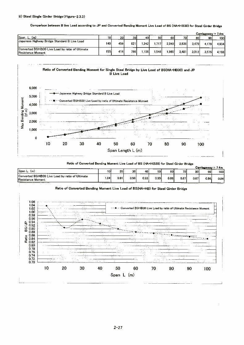
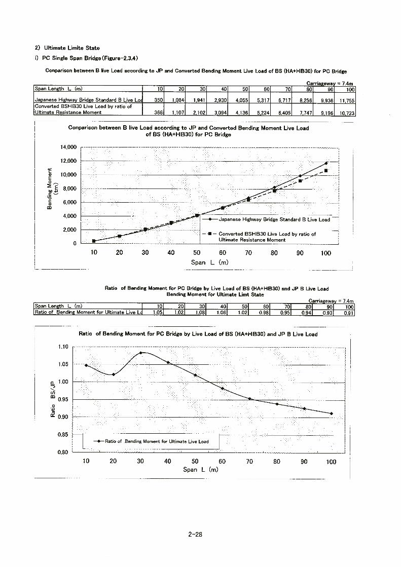

2-
29
3) Design Standard
(1) Geometric design of road
For roads to be rehabilitated according to this basic design, the geometric design values in Table-2.3.3 will be employed according to the Road Design Standard of Sri Lanka shown in Table-2.3.2.
Table-2.3.2 Road design standard
Bridge Road class
Traffic volume
(units/day) Road standard Topographic
conditions
Design speed
classification
Design speed(km/h) Remarks
Gampola Bridge (No.93)
A 300 ~
18,000
R3(improved) Mountainous Urban 50
Compliance with ADBⅢ
Muwagama Bridge
(No.239) B
300 ~
18,000
R3(improved)
Mountainous Urban 50 ―
Table-2.3.3 Values employed in the road geometric design
Design value
Item Unit Gampola Bridge
R3(shape changed) Muwagama Bridge
R3(shape changed) Design speed km/h 50 Roadway width(including shoulder) m 7.4(2 lanes;3.7+3.7)
Roadway Earth work section: 2.5
Bridge section: 1.5 Crossfall (asphalt concrete pavement)
Shoulder %
3.0
Minimum curve radius m 85 (72) Horizontal alignment Maximum crossfall % 6
Minimum grade % 0.3 Vertical alignment Maximum grade % 4 5
(2)Road width composition
The width composition of the bridge and approach road is shown in Table-2.3.4.

2-
30
Table-2.3.4 Width composition of bridge and approach road
(3)Pavement design
For the pavement design, the Sri Lanka Bridge Design manual (BDM) 1997 (RDA) will be applied. For pavement of bridge, the Asphalt Pavement Requirement of the Japan Road Association will be applied. The pavement composition shown in the final report of ADB III road improvement project will be employed only for the existing run-off section to the
Bridges Road class and standard
Component elements Components of cross section
11.4m
2.0m 3.7m 3.7m 2.0m
Bridge
Gampola Bridge (No. 93)
Road class:A Road standard:R3 (improved)
Roadway width:3.7m x 2 = 7.4 m Shoulder :1.8 m (Provided on both sides of earth work only) Sidewalk width:2.0 m (Provided on both sides on
bridge only) Curb and railings:Included
in width of sidewalk Gutters: 0.9 m (Provided on both sides of earth work only) Crossfall: Earth work; 2.5% (Asphalt pavement) Bridge; 1/60 (1.5%) Railings and mount-up of sidewalk: Handrail :h= 1.1m Mount-up:h≧225mm
11.0m
1.8m 3.7m 3.7m 1.8m
Approach road
11.4m
2.0m 3.7m 3.7m 2.0m
Bridge
Muwagama
Bridge (No. 239)
Road class:B Road standard:R3 (improved)
Roadway width:3.7m x 2= 7.4 m Shoulder :1.8m (Provided on both sides of earth work only) Sidewalk width:2.0m (Provided on both sides of bridge only) Curb and railings:Included
in width of sidewalk Gutters:0.9m (Provided on both sides of earth work only) Crossfall: Earth work; 2.5% (asphalt pavement) Bridge; 1/60 (1.5%) Handrail and sidewalk mount-up: Handrail :h= 1.1m Mount-up:h≧225mm
11.0m
1.8m 3.7m 3.7m 1.8m
Approach road

2-
31
approach road. The general pavement composition is as shown in Table-2.3.5.
Table-2.3.5 Road pavement composition Surface course
Binder course
Base course
Subbase course
Total thickness
Location of road
Classification of design
traffic volume
CBR Dense grade
Coarse grade
Crushed stone for
mechanical stabilization
Crusher run
Bridge - - 5cm - - - 5cm
①Approach road to
Gampola Bridge (No.93)
B 8 5cm 5cm 15cm 15cm 40cm
②Approach road to
Muwagama Bridge
(No.239)
B 8 (embankment)
5cm 5cm 15cm 15cm 40cm
③Diverging of daily road
to Muwagama Bridge
(No.239)
L 8 5cm
(coarse grade)
10cm 10cm 25cm
(4)Bridge design
① Design method
Design of the bridge concerned is made according to the Specification for Highway Bridges and its Explanation, December, 1996 (Japan Road Association) by means of the allowable stress method.
② Loads
a) Principal load
Ⅰ) Dead load
The dead load is the total weight of the bridge itself and the attachments. It is calculated on the basis of the unit volume weights shown in Table-2.3.6.

2-
32
Table-2.3.6 Unit volume weight of materials Material Unit volume
weight (kN/mm2)
Material Unit volume weight (kN/mm2)
Iron、steel 77 Plain concrete 22.5-23.0
Cast iron 71 Cement mortar 21.0 Aluminum 27.5 Wood 8
Reinforced concrete
24.0-24.5 Bituminous material
11
Prestressed concrete
24.5 Asphalt concrete 22.5
Ⅱ)Attachments and attached weight
Table-2.3.7 shows the type and weight of attachments.
Ⅲ)Live load
B live load to be applied
Table-2.3.7 Type and weight of attachments
Bridges Attachments Type
Quantity
(pieces) Weight (kN/m)
Steel pipe (galvanized)
φ225 1 0.93
Water supply Steel pipe (galvanized)
φ150 2 0.4
Gampola
Bridge
(No.93)
Telephone Steel pipe (galvanized)
φ150 5 1.23
Steel pipe (galvanized)
φ300 1 1.34
Water supply Steel pipe (galvanized)
φ225 1 0.93
Steel pipe (galvanized)
φ100 1 0.6
Muwagama
Bridge
(No.239) Telephone
Steel pipe (galvanized)
φ75 1 0.4

2-
33
Ⅳ) Impact of live load
Impact of live load is taken into account. The impact is calculated using the impact coefficient – i calculated from live load shown in Table-2.3.8.
Table-2.3.8 Calculation of impact coefficient i
Bridge type Impact coefficient I Remarks
Steel bridge T=
Regardless of whether T load or L load is used
T=
When T load is used
Reinforced concrete bridge T=
When L load is used
T=
When T load is used
Prestressed concrete bridge T=
When L load is used
Ⅴ)Prestressing force
Ⅵ)Effect of concrete creep
Ⅶ)Effect of concrete drying shrinkage
Ⅷ)Ground pressure
Ⅸ)Water pressure (static, running water)
Ⅹ)Buoyancy or uplift
b) Secondary load
Loads to be considered for combination of loads are shown below:
Ⅰ) Wind load
The wind load specified in the Specification for Highway Bridge will be applied.
Ⅱ) Effect of temperature change
Considering temperature fluctuations in Sri Lanka, the following will be applied:
Concrete: ± 15℃ (average 35℃、maximum 50℃、minimum 20℃)
10 25 + span length
20 50 + span length
20 50 + span length
7 20 + span length
20 50 + span length

2-
34
Note that 0.1 of the dead load or equivalent will be considered as a shoe horizontal component due to temperature change.
Ⅲ) Effect of earthquakes
The bridge design manual sets forth that the effect of earthquakes need not be taken into account because there is almost no record of earthquakes in Sri Lanka. Accordingly, the effect of earthquakes is not taken into account in this design.
c) Particular load
Particular loads are those to be taken into account depending on the bridge structural type, construction method, and bridge point condition. The following loads are considered:
Ⅰ) Load during construction
Ⅱ) Effect of movement of the fulcrum
Ⅲ) Braking force
Ⅳ) Collision load
d) Increased allowable stress due to combinations of loads
Increase in the allowable stress due to combination of loads is shown in Table-2.3.9.
Table-2.3.9 Increased allowable stress due to combinations of loads Load combination Incremental coefficient
Principal load 1.0
Principal load+ Temperature change
1.15
Principal load+ Braking load 1.25 Principal load+ collision load 1.5 Load during construction 1.5
③ Strength of materials to be used
a) Concrete
The design standard strength and Young’s modulus for concrete are shown below:

2-
35
Ⅰ) Design standard strength (28-day strength)
Prestressed concrete girder :σck=35N/mm2, 40N/mm2
Reinforced concrete slab, reinforced concrete girder :σck=24N/mm2
Reinforced concrete sidewalk, railing :σck=24N/mm2
Substructure(abutment・pier) :σck=21N/mm2, 24N/mm2
Foundation (cast-in-place pile) :σck=24N/mm2
Ⅱ) Young modulus
The Young coefficient calculated as shown in Table-2.3.10 is used.
Table-2.3.10 Young modulus value Design standard
strength (N/mm2) 21 24 35 40
Young modulus (kN/ mm2) 23 24 29 31
b) Re-bar
Re-bars are based on SD345 in accordance with the Specification for Highway Bridge.
c) Prestressing steel
Prestressing steel twisted wire and prestressing rod are in accordance with the Specification for Highway Bridge.
d) Steels
SS and SM steels in accordance with the Specification for Highway Bridge.
④ River conditions
Ⅰ)Design rainfall
Gampola Bridge: Q=2,650m3/sec
Muwagama Bridge:Q=4,550m3/sec
Ⅱ)Design high-water level
Gampola Bridge: Q=MSL 474.60m
Muwagama Bridge:Q=MSL 103.73m

2-
36
Ⅲ)Clearance under girder
In accordance with the Cabinet Order of Japan to ensure the value shown in Table-2.3.11.
Table-2.3.11 Clearance under girder Design rainfall
(m3/sec) 200<
200≦ <500
500≦ <2000
2000≦ <5000
5000≦ <10000
≦10000
Standard value(m)
0.6 0.8 1.0 1.2 1.5 2.0
Ⅳ)Pier’s flow detrimental ratio
6% or less according to the Cabinet Order of Japan
⑤ Soil constant
As a result of field survey, the soil constant was set as shown in Appendix, Soil Constant.

2-37
2-3-2 Basic Design
1) Selection of bridge points
(1) Bridge locations
Reconstruction was determined to be necessary after a damage survey of the condition of the bridges concerned. On the basis of the results of a field survey, selection of new bridge points was reviewed for three cases: the current position, the upstream side and the downstream side of the existing bridges in terms of the possibility of acquiring needed land, the geology, environmental conditions, and traffic through temporary roads. Agreement was reached on the following points:
① Gampola Bridge
The new bridge will be constructed on the upstream side of the existing one for the following reasons: ・There would be no substitute road in the suburb if a new bridge were to be
constructed at the current location. ・Provision of a temporary bridge and temporary road during the work period would
be geologically difficult if the plan designates the existing bridge position. ・A temple and lime trees are on the left of downstream side, which make transfer of
the bridge difficult. ・If the new bridge were constructed on the downstream side, adverse effects such as
scouring, etc. might occur until the existing bridge is removed. ・It was confirmed that part of an elementary school on the right bank of the
upstream side can be used. ・A temporary bridge becomes necessary when the plan designates the existing
bridge position. This is disadvantageous in terms of both work period and cost.
② Muwagama Bridge
The new bridge was planned for the downstream side of the existing one for the reasons given below. Before planning the bridge for the downstream side where it is susceptible to effects of scouring caused by the existing one, thorough discussions were held with authorities concerned. ・There would be no substitute road in the suburb if a new bridge were to be
constructed in the current location. ・Provision of a temporary bridge and temporary road during the work period would
be geologically difficult if the plan designates the existing bridge position. ・A Ratnapura vegetable market on the right bank of the upstream side makes land

2-38
acquisition difficult. ・A temporary bridge would have to be erected if the existing bridge position were
used. Because the approach road on the right bank runs on the 8 m embankment, the scale of the temporary road would be large.
・When the new bridge is constructed on the downstream side, adverse effects such as scouring may occur. If necessary, scouring and other adverse effects can be avoided by proposing a structure without piers, such as a single span bridge.
(2) Distances from existing bridges
The distances between existing and new bridges were determined in view of the
points outlined below. As a result, a distance of 16.5 m between road centers will be secured between the existing and new bridges.
① The location should be where construction work in the proximity does not
affect existing bridge piers
The existing bridges are 70 years or more old and heavily damaged. When new piers are to be provided for the new bridge, the distance (where no measure is taken) must be secured to prevent adverse effect of the construction work in the neighborhood of the existing piers.
② Alignment of approach roads
The alignment of existing approach roads will not be changed substantially.
③ Avoidance of effects on the wing of existing bridge abutments
The location of new bridge abutments must be such that foundation piles do not interfere with the caisson foundation built for the existing bridge abutment wing.
④ Sufficient distance must be secured for superstructure, substructure, and
foundation work.
A distance of 1.0 m or more must be secured between the temporary bent, landing bridge, cofferdam, and scaffold and the existing bridge.

2-39
2) Topological and geological conditions
(1) Gampola Bridge
① Outline of the geology
The location planned for the Gampola Bridge is about 500 m above sea level in a central highland surrounded by precipitous mountains. The bridge is planned in a narrow plain portion of this terrain. The right bank is relatively flat and the left bank is a low hill having outcrops of soft to hard rock mass.
Around the bridge point, the topography shows a V-shaped valley due to erosion and locations where bedrock (schist, gneiss) is exposed in the form of hard rocks in the river bottom. It is therefore thought that the Mahaweli River is an eroding river. The existing bridge is heavily eroded at the foundation of existing piers and the river bed is considered to have lowered considerably. In the past, moreover, the river channel moved toward the relatively flat right-bank side, which is presumed to have caused significant gouging of bedrock toward the right bank side.
② Geological and ground composition
Boring was conducted at six points upstream and downstream of the existing bridge. The result is shown below. (See Fig.-2.3.5)
The granitic gneiss (hard rock class) that is bedrock dips from the left bank to the right bank side and is at a depth of 5 m on the left bank and about 20 m on the right bank. Heavily weathered granitic gneiss (clayey soil: N value of about 7) has built up a depth of 2 m on top of the bedrock. Loose sandy layers and soft clayey soil layers have accumulated from the top of the weathered rock to the ground surface. On the left bank, distribution of rolling stones and cobbles is observed in a relatively shallow position. However, the middle portion of the river is heavily eroded, with only river deposit of about 1 m present on top of the heavily weathered soil.
On the right bank, a loose sandy soil layer that may have originated from backfilling during construction of the existing bridge is distributed at a thickness of about 11 m below the ground surface. Moreover, a cobble layer of about 20 cm exists on the bedrock.
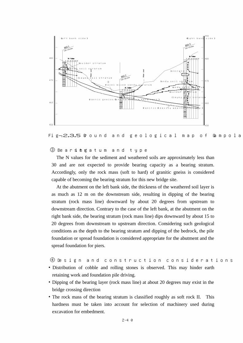
2-40
Fig. -2.3.5 Ground and geological map of Gampola Bridge planned point
③ Bearing stratum and type
The N values for the sediment and weathered soils are approximately less than 30 and are not expected to provide bearing capacity as a bearing stratum. Accordingly, only the rock mass (soft to hard) of granitic gneiss is considered capable of becoming the bearing stratum for this new bridge site.
At the abutment on the left bank side, the thickness of the weathered soil layer is as much as 12 m on the downstream side, resulting in dipping of the bearing stratum (rock mass line) downward by about 20 degrees from upstream to downstream direction. Contrary to the case of the left bank, at the abutment on the right bank side, the bearing stratum (rock mass line) dips downward by about 15 to 20 degrees from downstream to upstream direction. Considering such geological conditions as the depth to the bearing stratum and dipping of the bedrock, the pile foundation or spread foundation is considered appropriate for the abutment and the spread foundation for piers.
④ Design and construction considerations
・Distribution of cobble and rolling stones is observed. This may hinder earth retaining work and foundation pile driving.
・Dipping of the bearing layer (rock mass line) at about 20 degrees may exist in the bridge crossing direction
・The rock mass of the bearing stratum is classified roughly as soft rock II. This hardness must be taken into account for selection of machinery used during excavation for embedment.
50
GH= 478.44m BH-1
Grantic gneiss(Soft to medium hard rock)
Boulder stratum
Clayey soil stratum
30 40 500 10 20
Sandy soil stratum
N - ValueN - ValueN - ValueN - Value
BH-2
Gravel mixed sandy stratum
N - ValueN - ValueN - ValueN - Value0 302010 40
GH= 465.42m
(Left bank side)
GH= 479.46m
Granitic(heavily weathererd rock)
Sandy soil stratum
Boulder stratum
Clayey soil stratum
Sandy soil stratum
Concrete
N - ValueN - ValueN - ValueN - Value403020100 50
(Right bank side)
BH-3

2-41
(2) Muwagama Bridge
① Outline of geology The Muwagama Bridge site is about 100 m above sea level and near the boundary
between the central highland and southwestern areas. The surrounding mountains are relatively gentle, with a ridge line running from northwest to southeast, which indicates the direction of tectonic activity. Mountains in the neighborhood are relatively weathered. Non-weathered rocks or blocks several meters in diameter are frequently left in weathered soil of the ground or talus material in the form of rolling stones.
The planned bridge site is located in a narrow plain portion where rivers running through this terrain join. There is a small hill with exposed soft to hard rocks on the left bank and a lowland is spreading on the right bank. This appears to be the reason why the bedrock on the right bank is gouged to a great extent and there are many points with thick soil sedimentation transported during flood. Though the river bed shows signs of scouring, it is not as heavy as the case of the Gampola Bridge
② Geological and ground composition
In order to grasp the ground and geological conditions at the Muwagama Bridge site, four boring surveys were conducted on the downstream side of the existing bridge. The results were evaluated through comparison with the existing data. This is described below. (See Fig.-2.3.6)
・ Left Bank: For the bedrock, the charnockite gneiss rock with a hardness
equivalent to the medium hard rock is distributed at a depth of 15 – 20 m. Clayey soil layers are deposited on top of this, with intervening loose sandy or clayey soil layers, a total of 8 m thickness, including one with a maximum thickness of 4 m, which contain rolling stones and cobble layers.
・ Right bank:The bedrock is granitic gneiss (medium hard to soft II class) present
at the depth of 20 – 25 m below the surface. On top of this bedrock, heavily weathered soil (N value of about 20) of granitic gneiss is deposited with the thickness of 1 – 7 m. There are alternate layers of clayey and sandy soil on top of heavily weathered soil. In the deeper position, there are sandy layers (gravel mixed sand to sand) and sand mixed clay layers with N values of 40 or more.

2-42
Fig.-2.3.6 Ground and geological map of planned site for Muwagama Bridge
③ Bearing stratum and type
・Left bank As N values exceeding 30 are not observed consecutively for 5 m or more
in the sediments and the weathered soil layer, it is considered appropriate to use the bedrock, that is the charnockite gneiss, and granitic gneiss, as a bearing stratum. It is highly possible that the rock mass line at the left bank abutment dips steeply from the downstream side by 70 – 80 degrees to the upstream side. It is considered appropriate to use a pile foundation.
・Right bank It was confirmed that the layer with an N value of 30 or more continues for
7 – 8 m from a point 11 m below the ground surface. Considering that its continuity could not be confirmed horizontally and that a heavily weathered soil layer with an N value of 20 or less is distributed with a thickness of about 5 m, it may be appropriate to use the bedrock of granitic gneiss (soft I to soft II) as a bearing stratum.
It is possible that the rock mass line at the abutment dips steeply at about 60 degrees from the upstream to downstream side. Considering the depth to the bearing stratum and the dip of bedrock, a pile foundation is appropriate for an abutment and pier.
④ Design and implementation conditions
・Distribution of cobble and rolling stones is expected to be remarkable on the left bank, which may hinder earth retaining and foundation pile driving.
40 50200 10 30N - ValueN - ValueN - ValueN - Value
Clayey stratum
Clayey stratum
GH= 96.61mExt BH-3
N - ValueN - ValueN - ValueN - Value
BH-4GH=100.03m
Sandy soil stratum
(Right bank side)
Clayey stratum
Charnockite gneiss(Soft to medium hard rock)
Lime stone
Clayey stratum
Granitic gneiss(Soft to medium hard rock)
(Heavily weathered rock)Granitic gneiss
Boulder stratum
3020 400 10 50
Sandy soil stratum
Boulder stratum
Boulder stratum
50N - ValueN - ValueN - ValueN - Value
20 300 10 40
(Left bank side)
N - ValueN - ValueN - ValueN - Value
GH=100.61mExt BH-7
GH= 98.11mExt BH-6
4030200 10 50
Ext BH-5
Sandy soil stratumSandy soil stratum
N - ValueN - ValueN - ValueN - Value
GH= 93.21m
0 10 4020 30 50

2-43
・It is highly possible that the bearing stratum (rock mass line) dips steeply at about 60 – 80 degrees. A detailed review is necessary before designing the foundation work. ・It is possible that intermediate layers with an N value of 30 – 50 may exist and that cobble and rolling stones are distributed in large quantity. These facts must be taken into account when selecting the foundation pile driving method.
3) Hydraulic and hydrologic conditions
(1) Outline of the river basin at bridge locations
① Outline of rivers
This section describes the result of river and hydrologic surveys of Gampola and Ratnapura. Gampola Bridge No. 93 is planned upstream of the Mahaweli River. This river has the largest basin area in Sri Lanka and also the largest runoff. The Muwagama Bridge No. 239 crosses the Kalu River, which has the fifth largest runoff. The basins of these rivers are outlined below.
(a) Mahaweli River
Kotmale dam is about 16.5 km upstream of the planned bridge location. The basin
area upstream of the planned bridge is about 888km2. The highest altitude of the
headwater is 2,100 m, and the riverbed around Gampola Bridge site is 460m above sea
level. The area is mostly steep forest land, with villages and tea fields located
in various parts of the land. The basin of Kotmale dam has a governing area
substantially affecting the Gampola Bridge location. Data on this dam is shown in
the table below.
Table-2.3.12 Data of Kotmale dam
Name Kotmale dam
Completion 1985
Type Rock fill dam
Crest length (m) 600
Dam height (m) 87 (EL 706.5 m )
Flood operating level 704.3 m
Flood storage capacity 181,100,000 m3
Design high water level 703 m

2-44
Reservoir capacity 174,000,000 m3
Lowest operating level 665 m
Objectives Power generation 200 MW, irrigation, municipal water, flood control
Administrator Mahaweli Authority
Kotmale Dam effectively controls floods for this basin. Since operation of this dam started, the maximum inflow has not been directly related to the maximum outflow in many cases. Namely, the maximum outflow was not observed on days when maximum inflow occurred, indicating that the storage effect of the dam is high.
An inflow of 27.1 x 10⁶ m³(hereinafter, x 106 m³ should be read as million m³) on October 7, 1995 caused a maximum outflow of 12.3 million m³ on October 9. This can be considered outflow related to a flood. The storage volume in this case is as follows.
Table-2.3.13 Kotmale dam level - Storage capacity
Reservoir level
Year/month/day of occurrence
Storage capacity (Million m³)
698.2 1995-10-7 144.3
702.4 1995-10-8 168.8
703.0 1995-10-9 172.0
In this case, the dam that received an inflow of 27.1 million m³ on October 7 stored a flood of 27.7 million m³ to reach the design high water level until October 9, that is, two days later. The average rainfall was 123 mm and more at the Ramboda precipitation station and 128 mm at the Hatton precipitation station, indicating approximate similar readings. Data on the rivers and river courses are shown in Table-2.3.14.
(b) Kalu River
The basin area of this river upstream from the Muwagama Bridge location is about 614 km2. The maximum altitude of the headwater is 1523m, and the river reaches the planned bridge location after running for about 58 km. The river bed is 90.7 m above sea level. The mean annual rainfall within the basin is 157 mm, which is larger than that of the Mahaweli River. Other data is shown in Table 2.3.14. At

2-45
the bridge location, on the left bank, a tributary, the Ei Oya River with a basin area of about 3 km2, merges, but its contribution to flood discharge as a whole is not much.
② River data
River data is shown in the table below.
Table-2.3.14 River and river channel data
Name of river Mahaweli River Kalu River
Total basin area of main river(km2) 10,448 2,719 Basin area concerned(km2) 888 614 Dam basin area(km2) 544 --- Tributary basin area(km2) 344 --- Max river bed altitude(m) 2,100 1,523 Max river bed altitude of tributary(m) 1,150 --- Min river bed altitude(m) 460 90.7 Total length of main river(km) 335 129 Length of channel concerned(km) 75.4 58 Length of channel downstream of Dam
(km) 16.5 ---
Length of tributaries(km) 43.0 ---
Coefficient of river regime* 1,000 or more
1,000 or more
Typical grain size of river bed (dr) 0.1cm 0.04cm Average water depth in low channel(H1) 3.5m 5.5m
River width/depth ratio(B/H1) 64.3 5.9 Depth/grain size ratio (H1 /dr) 5690 22700
*Coefficient of river regime= Largest record flood / Recorded lowest water level
③ Determination of the roughness coefficient of river
The roughness coefficient of the low channel in each river was determined as indicated below, while referring to Strickler’s equation, the Guidebook for Planning River Channels of the River Bureau of the Ministry of Construction, hydraulic formulas of the JSCE, past water levels known from interviews, and results of analysis of grain size of river bed materials.
(a) Mahaweli River
Local flood levels known from interviews vary greatly. At a point 600 m downstream of the Gampola bridge with the water level of 8 m, the roughness
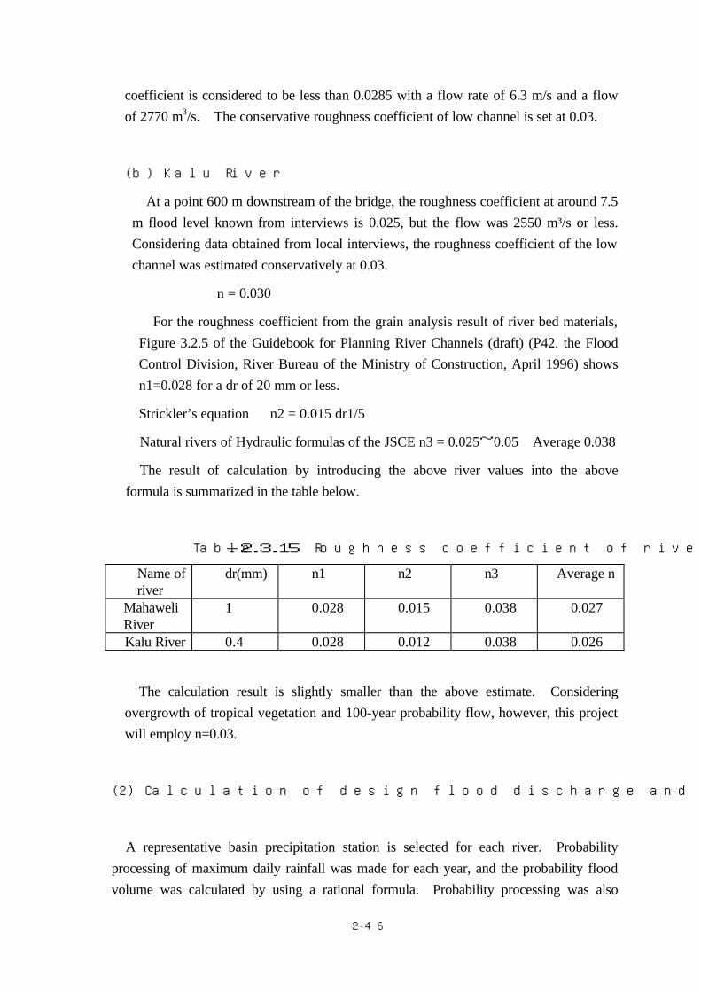
2-46
coefficient is considered to be less than 0.0285 with a flow rate of 6.3 m/s and a flow of 2770 m3/s. The conservative roughness coefficient of low channel is set at 0.03.
(b) Kalu River
At a point 600 m downstream of the bridge, the roughness coefficient at around 7.5 m flood level known from interviews is 0.025, but the flow was 2550 m³/s or less. Considering data obtained from local interviews, the roughness coefficient of the low channel was estimated conservatively at 0.03.
n = 0.030
For the roughness coefficient from the grain analysis result of river bed materials, Figure 3.2.5 of the Guidebook for Planning River Channels (draft) (P42. the Flood Control Division, River Bureau of the Ministry of Construction, April 1996) shows n1=0.028 for a dr of 20 mm or less.
Strickler’s equation n2 = 0.015 dr1/5
Natural rivers of Hydraulic formulas of the JSCE n3 = 0.025~0.05 Average 0.038
The result of calculation by introducing the above river values into the above formula is summarized in the table below.
Table-2.3.15 Roughness coefficient of rivers concerned
Name of river
dr(mm) n1 n2 n3 Average n
Mahaweli River
1 0.028 0.015 0.038 0.027
Kalu River 0.4 0.028 0.012 0.038 0.026
The calculation result is slightly smaller than the above estimate. Considering overgrowth of tropical vegetation and 100-year probability flow, however, this project will employ n=0.03.
(2) Calculation of design flood discharge and design flood levels at bridge locations
A representative basin precipitation station is selected for each river. Probability processing of maximum daily rainfall was made for each year, and the probability flood volume was calculated by using a rational formula. Probability processing was also

2-47
made on observation records of water levels and flows. The flood level was calculated by applying the above roughness coefficient to each probable flood volume. The analysis flow is shown below.
Fig -2.3.7 Analysis flow
Selection of precipitation station
Annual max daily rainfall
Probability processing of daily
rainfall
Calculation of design flood discharge
Calculation of level and flow at a bridge location of each river
Kotomale dam discharge rate
River bed grain size
Level and flow calculation
Comparison with flow of related basin
Non-uniform flow calculation
Rational formula
Dam in the river cross direction
Calculation of probability annual flow
Study on existing flood level
Comparison with flow in related basin

2-48
① Basin mean daily rainfall in each probable year
On the basis of maximum daily rainfall data at each station, the probable daily rainfall was calculated as follows according to the Thomas Plot Method.
Table-2.3.16 Probable daily rainfall at each station (mm)
Probability year
Ramboda Hatton Yellaben Ratnapura
(1) (2) (3) (4)
1/100 252 226 252 394
1/50 217 204 216 345
1/10 138 148 134 239
1/2 55 95 50 147
The basin average daily rainfall for each river was calculated as follows:
Mahaweli River(in dam basin) R24=〔(1)+(2)〕/2
Mahaweli River (remaining basins) R24=(3)
Kalu River Ratnapula R24=(4)
The calculation result of probable basin mean daily rainfall of each river is shown in Table-2.3.17.
Table-2.3.17 Basin mean rainfall
Probability year
Mahaweli River Dam basin
Mahaweli River
Other basins
Kalu River
1/100 239 252 394 1/50 211 216 345 1/10 143 134 239 1/2 75 50 147
② Calculation of flood runoff
The basin area of the Mahaweli River includes 544km2 for the Kotmale Dam basin and 344 km2 for other basins. In the case of the Kalu River, the basin area is 614 km2 . The Flow of each basin is calculated using a rational formula.

2-49
There are no level and flow stations near the planned site of the Muwagama Bridge. For the Kalu River, the top ranked level record of EL103.73 was on August 15, 1947, and a second highest level record of EL103.58 has been recorded. RDA has independently calculated the design flood level for the bridge concerned by using the top ranked flood level record. Using this as a reference, comparison is made with the flow calculated from the rational formula (Rational formula).
③ Calculation of flood concentration time
As calculation equations, Kraven’s equation, equation of Public Works Research Institute, etc. are available. In this project, Rziha’s equation that produces intermediate values is employed:
Rziha’s equation T=L/V、V=20(h/L)0.6
where T:Flood concentration time(h);V:Concentration speed(m/ s);and h:
Head(m)L:Channel length(m)are used.
Table-2.3.18 Flood concentration time for each river
River condition Dam discharge to Mahaweli River
Other basins of Mahaweli River Kalu River
h(m) 703-460=243 710 1,432
L(m) 16,500 43,000 58,000
V(m/s) 1.6 1.7 2.2
T(h) 2.9 7 7.3
④ Calculation of rainfall within the flood concentration time
The rainfall within the flood concentration time is calculated from the basin mean daily rainfall as follows:
Rt = R24(t/24)k
where, R24:Daily rainfall t:Flood concentration time; and K:Constant (0.3) are used.

2-50
Table―2.3.19 Daily max rainfall and rainfall within the flood concentration time
(Rt) for each river (Unit mm)
Probability year Dam discharge to Mahaweli River
Other basins of Mahaweli River Kalu River
R24 1/100 239 252 394 1/50 211 216 345 1/10 143 134 239 1/2 75 50 147 t (h) 2.9 7 7.3 Rt(mm/t) 1/100 127 174 276 1/50 112 149 241 1/10 76 93 167 1/2 40 35 103 (Rational formula) Calculation of Q=1/3.6 fr A
where Q:Peak runoff rate(m3/ s) f :Runoff coefficient = 0.7(Mountain and tea field)
r :Rainfall within flood concentration time(mm/h); and A:Basin concerned (km2) are used.
Table-2.3.20 Probable rainfall and flow for each basin
Probability year Dam discharge to Mahaweli River
Other basins of Mahaweli River Kalu River
A(Km2) 544 344 614 R(mm/h)
1/100 43 25 38 1/50 39 21 33 1/10 26 13 23 1/2 13 5 14
Q(m3/s) 1/100 4548 1672 4537 1/50 4125 1405 3940 1/10 2750 870 2746 1/2 1375 334 1671

2-51
Table-2.3.21 Flow at Gampola on Mahaweli River when flood discharge of
Kotmale Dam is taken into account Probability
year Rainfall
(mm)
Basin area
(Km2)
Runoff Dam inflow
(M m³)
Flood storage capacity
(M m³)
Discharge
(M m³)
Discharge rate
(m³/s)
Merge rate
(m³/s)
1/100 239 544 0.7 91.01 7.1 83.91 971 2643
1/50 211 544 0.7 80.35 7.1 73.25 848 2253
1/10 14.68 170 1040
1/2 7.78 90 424
Note that the runoff for 1/10 and 1/2 was so small that the actual discharge was processed on the basis of probability and added.
⑤ Assumed flood effects on the downstream area
It is assumed that the rainfall with a 100-year flood level flows into the Kotmale dam while it maintains the maximum past storage record level of 703 m. Such an inflow is calculated as follows.
239mm×544km2×0.7=91.01million m³.
The dam flood storage capacity is 181.1-174=7.1million m³,
so that it is necessary to discharge 91.01-7.1=83.91million m³.
This results in a discharge of 971 m³/sec.
This discharge volume is the maximum flow that may affect the bridge location concerned, which is the flow with a 100-year flood level to be calculated as 1672+971=2643 m³/s.
Similarly, the flow with a 50-year flood level is 1405+848=2253 m³/s.
⑥ Results of calculation to determine design flood discharge
The design flood discharge is calculated as shown in Table-2.3.22.
Table-2.3.22 Results of calculation to determine design flood discharge(m3/s)
Probability year Mahaweli River Kalu River
1/100 2650 4550
1/50 2300 3950
1/10 1050 2759
1/2 450 1700
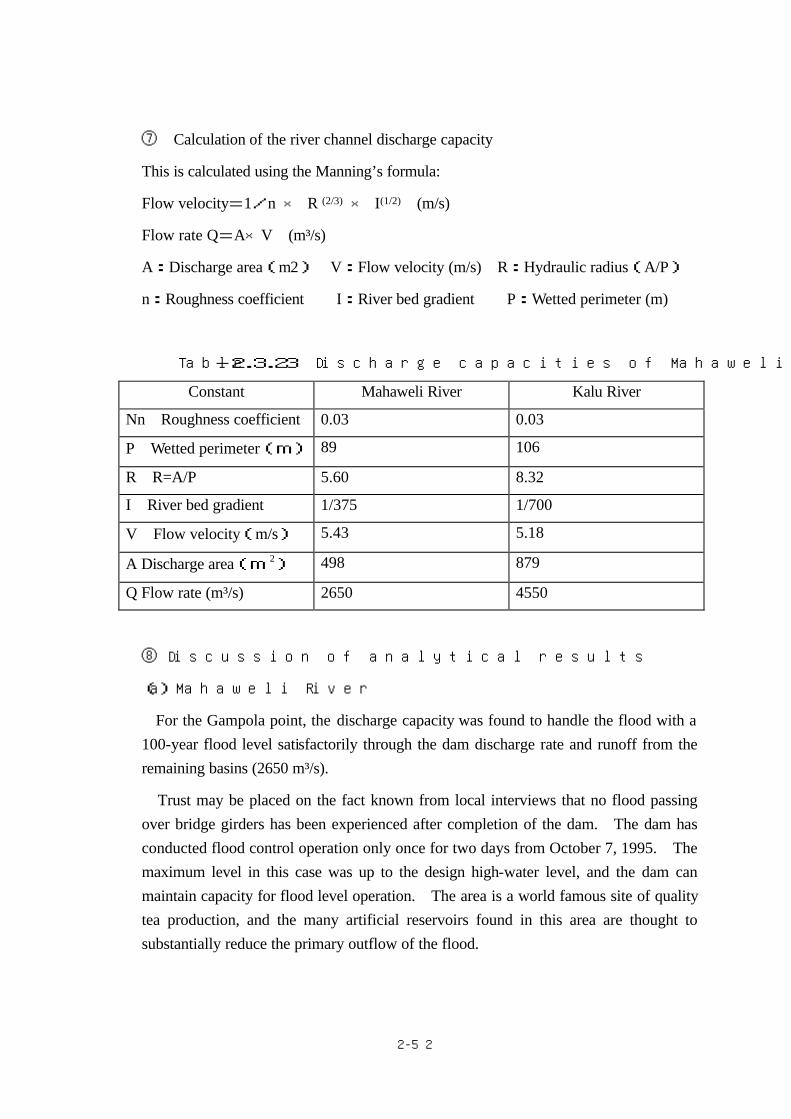
2-52
⑦ Calculation of the river channel discharge capacity
This is calculated using the Manning’s formula:
Flow velocity=1/n × R (2/3) × I(1/2) (m/s)
Flow rate Q=A×V (m³/s)
A:Discharge area(m2) V:Flow velocity (m/s) R:Hydraulic radius(A/P)
n:Roughness coefficient I:River bed gradient P:Wetted perimeter (m)
Table-2.3.23 Discharge capacities of Mahaweli and Kalu Rivers
Constant Mahaweli River Kalu River
Nn Roughness coefficient 0.03 0.03
P Wetted perimeter(m) 89 106
R R=A/P 5.60 8.32
I River bed gradient 1/375 1/700
V Flow velocity(m/s) 5.43 5.18
A Discharge area(m 2) 498 879
Q Flow rate (m³/s) 2650 4550
⑧ Discussion of analytical results
(a) Mahaweli River
For the Gampola point, the discharge capacity was found to handle the flood with a 100-year flood level satisfactorily through the dam discharge rate and runoff from the remaining basins (2650 m³/s).
Trust may be placed on the fact known from local interviews that no flood passing over bridge girders has been experienced after completion of the dam. The dam has conducted flood control operation only once for two days from October 7, 1995. The maximum level in this case was up to the design high-water level, and the dam can maintain capacity for flood level operation. The area is a world famous site of quality tea production, and the many artificial reservoirs found in this area are thought to substantially reduce the primary outflow of the flood.
2-53
(b) Kalu River
For the Muwagama, Ratnapura point, the calculation of flood with a 50-year flood level produced a value lower than the recorded highest water level (103.73 m), indicating that there is no particular problem. The calculation result with a 100-year flood level is higher than this level. In upstream landside areas protected by the bank, there is a wide area of lowland whose altitude is lower than 100 m. The flood will deluge this lowland, geologically making it impossible for the water level to rise above this level.
(3) Channel and river bed fluctuation of each river
On the basis of the results of a field survey this time and by referring to the map, changes of channels and river bed fluctuation are described for each river.
① Mahaweli River
In the case of this channel, mountain rivers reach the planned bridge location concerned. Since the geological map shows almost no change, the river channel is expected to be free from change in the future.
Not many houses, but many tea fields are on the basin upstream of the bridge location. The population shows a slight downward trend. Concerning the river bed fluctuation, transport of sediments has decreased since construction of the Kotmale Dam on the upstream side. The river bed lowering is promoted further by quarrying of river bed materials upstream and downstream of the bridge. Since construction of the dam, the river bed has lowered by about 4m.
Quarrying of river bed material upstream and downstream of the planned bridge location must be considered together with local scouring and future measures to prevent lowering of the river bed.
The friction velocity U*2 (cm2/s2) and typical grain size dr (cm), which are shown in
Fig.-3.15 on page 22 of the Guidebook (draft), were plotted to verify the river channel characteristics. The result showed that the channel of the Mahaweli River tends to increase in width. As the rock mass exists about 2 m and below the existing river bed, scouring will be to this rock mass at most. Accordingly, embedment of piers and surrounding countermeasure works are considered sufficient to cope with scouring.

2-54
② Kalu River
In upstream landside areas of this river channel, the ground height is low on both the right and left banks. At the bridge point, the existing clearance under girder is enough for the design flood level.
The wide floodplain with 100 m or less ground altitude in upstream landside areas will allow the flood to deluge the plain, preventing the flood from threatening the existing clearance under girder. Similarly to the case of the Mahaweli River, quarrying of river bed material is done here, promoting lowering of the river bed.
Table-2.3.24 Survey on flood mark of rivers concerned
Year/month/day of occurrence
Mahaweli River (EL m)
Kalu River (EL m)
1947-8-5 484.96
1941-5-13 481.95
1978-11-23 481.34
1974-7-27 481.08
1933-5-24 480.84
1913-12-6 480.69
1940-5-18 480.38
1957-12-23 479.96
1913-10-5 479.96
1906-10-27 479.67
1956-6-23 479.45
1968-5-5 479.42
1942-7-15 103.73
1996-6-8 103.58
The bridge surface altitude of Gampola Bridge over the Mahaweli River is EL483.5 m. The past flood record shows overflowing over the bridge surface, but since completion of the Kotmale Dam in 1985, no such flood has been recorded.

2-55
The flood mark of the Mahaweli River was found at the Gampola Station building located 0.7 km upstream of the left bank.
(4) Result of calculation of water level
As a rule, the existing cross section view was used for the river cross section during calculation of various hydraulic data at each bridge point. As a result of calculation, design flood discharge and flood level for the design probability year (100-year) are shown below.
Table-2.3.25 Design flood discharge and design high water level at bridge points
Name of river Mahaweli River Kalu River
Design flood discharge(m3/s) 2650 4550
Design high water level(m) 474.60 104.40
Flow velocity(m/s) 5.43 5.18
Recorded highest water level (value employed by RDA)
No level rise record since construction of Kotmale dam
103.73
High-water level employed for this project(m)
474.60 103.73
※ The design high-water level of the Kalu River was calculated to be 104.40 m, but is assumed to be 103.73 m in consideration of geological conditions and existing maximum observed levels. The wide floodplain with 100 m or less ground altitude in upstream landside areas spreads, which will allow floods to deluge the plain, preventing floods from threatening the existing clearance under girder.
(5)Bridge size
In consequence, the bridge length required in terms of river hydrology and hydraulics is considered to be as follows.
a) Gampola Bridge
The Mahaweli River channel is considered to be stable, and there will be no problem if the existing river channel is secured. As the new bridge will be

2-56
designed at a height nearly the same as the existing bridge, a sufficient allowance will exist from the design flood level to clearance under girder.
② Muwagama Bridge
The Kalu River channel is also stable. Considering the river sectional shape on both the upstream and downstream sides, there is no need to increase the bridge length further. It is considered rational to set the new bridge length at the existing length.

2-57
4)Road design
(1) Road horizontal alignment
①Alighment design
The Gampola Bridge will be built approximately parallel to the existing road, with the bridge section shifted toward the upstream side. At the Nuwara Eliya side of approach road, the alignment is designed not to interfere with the main building of Teachers College. An alignment ensuring continuation of the existing intersection function for the Gampola side has been selected. The Muwaguma Bridge will be built approximately parallel to the existing road, with the bridge shifted to the downstream side. The approach road is planned as run-off to the existing alignment.
②Scope of implementation
The scope of implementation is shown in Table-2.3.26.
Table-2.3.26 Scope of construction of approach road
Site Start point End point
No.93
Gampola Bridge
・Gampola side
ADB road improvement project
Route A5 Measurement point BC
No.133
(about 40 m up to box culvert end)
・Nuwara Eliya side
JBIC road improvement project
Route A5 Measurement point EC
No.134
・Nawarapitiya side Route A013
No.239
Muwagama
Bridge
・Ratnapura side
Route B390
・Ratnapura side
Route B390
③Width composition
The width composition is shown in Table-2.3.4. For the road composition, a total width of 2.0 m and an effective width of 1.5 m have been secured for the bridge section. The reasons are as follows: a) A width of 2.0 m is planned for sidewalks in the urban area on the RDA side. b) In the bridge plan, based on aid from other donors, a total width of 2.0 m and an
effective width of 1.5 m have been secured. c) The route covered by this project corresponds to Type 4, Class 2 of the Japanese
Road Structure Ordinance, so that the effective width of 1.5 m must be secured. The width for the sidewalk has been secured within a range sufficient to ensure the
safety of pedestrians.

2-58
(2) Road vertical alignment
The vertical alignment was determined in view of the following conditions: ① Gampola Bridge
The elevation is aligned to the existing bridge elevation at the abutment. The approach road will have the alignment already planned in the road improvement supported by the JBIC and the ADB.
② Muwagama Bridge
The elevation determined by adding the free board and girder height to the design high-water level becomes higher than the existing bridge height. Accordingly, a grade of about 3% is provided to the bridge so that the bridge connects to the existing road through the approach road.
(3) Road drainage
Road drainage is provided by restoring the existing drainage device. Basically, U-gutters are arranged along the road, with cross culvert and catch basin provided as required. (4) Road structures
Where the toe of the embankment slope of road earthwork interferes with the boundary
with private land to a great extent, retaining walls, etc. are to be provided as required to
reduce the scope of land acquisition. The basic wall structure will be wet masonry,
which is employed most frequently in Sri Lanka.
(5) Revetment and bed protection works
The channel varies greatly depending on revetment and bed protection works. In this
project, these protection works are provided to ensure a stable channel and bridge safety, etc.
The approach embankment on both sides of the bridge may suffer erosion because the river is meandering greatly before and after the bridge and increase in water volume during the wet season may cause the flow directly against the river slope.

2-59
Accordingly, the slope in the river that may affect structures is protected with wet masonry. The bed protection work is provided around abutments and piers. Table-2.3.27 shows a comparison of the revetment types.


2-61
5) Bridge design
(1)Abutment location
The Mahaweli and Kau Rivers where the bridges are located are among the largest
rivers in Sri Lanka. The basin width is 50 m or more even during the normal season. There is no levee near the planned site for bridge and the river is flowing in a natural condition. It is necessary to select an abutment location that does not hinder flood control and to conside the river and topographical conditions and the existing bridge location. The abutment location of each bridge is shown below.
① Gampola Bridge
This bridge is already over 70 years old and has suffered flooding several times. It was submerged only once during a great flood in 1947. The bridge has allowed flood waters to flow through the section between the existing abutments during floods occurring almost every year, and the field survey showed no mark of substantial erosion. Therefore, the new bridge is planned with abutment locations aligned to the existing bridge while maintaining the same flow through section as the existing bridge.
② Muwagama Bridge
The topograpy at the bridge point is a relatively flat lowland on the Ratnapura side, with an embankment approach road (H=8). There is a steep slope on the opposite bank. An abutment is erected on the slope. According to the hearing, inundation occurs several times a year around the planned site, and houses in the neighborhood of the bridge are flooded. Being located in a relatively elevated position, this bridge has never been flooded in the 80 years since it was built. The field survey found no signs of large-scale erosion either. Accordingly, the new bridge abutment position is aligned to the existing one while maintaining the same flow-down section as the existing bridge.
(2)Bridge length
To maintain the existing flow-down section, the bridge length was determined as
shown in Table-2.3.28. It is designed to prevent the front wall of the abutment from protruding toward the river side beyond the existing abutment.

2-62
(3)Pier location(span arrangement)
The pier location must be determined while considering the effects of blockage of
flow by bridge piers and blockage with drift wood. Therefore, the pier location is to be determined according to the Cabinet Order Concerning Structural Standards for River Management Facilities while referring to the following standards:
Standard span length:More than the value calculated in Fig-2.3.7. For the
existing piers, the standard span length was set to 15 m because it will be removed after completion of the new bridge.
Pier`s flow detrimental ratio:6% or less
The existing and standard span lengths of both bridges are shown in Table-2.3.29. As the existing span length is approximately equivalent to the standard span length, piers will be provided basically in alignment with the existing pier locations. Therefore, the expected span arrangements are as indicated below. These arrangements for the two bridges are also compared.
① Gampola Bridge:Single span(Bridge length=100m span length 98.2 m)
Two spans(Bridge length =99m span length 48.7 m×2) Three spans(Bridge length=99m span length 32.6 m×3)
② Muwagama Bridge:Single span(Bridge length =99m span length 97.2 m) Two spans(Bridge length=98 m span length 48.2 m×2) Three spans(Bridge length=22+55+22=99)

2-63
Table-2.3.28 Determination of bridge length Gampola Bridge Muwagama Bridge
Feet inch
311’6” 308’00” Pier distance of existing bridge ( Distance between abutment front)
m 94.95 93.88
Span arrangement Single span
Two spans
Three spans
Single span
Two spans
Three spans
Bearing support end distance(a)
mm 700 450 400 700 450 300
Bearing support width(b)
mm 1000 800 600 1000 800 500
Bearing support end - girder end distance (c)
mm 300 300 200 300 300 200
Girder expansion gap(d)
mm 100 100 100 100 100 100
Shoe width (e=a +b+c+d)
mm 2100 1650 1300 2100 1650 1100
Bridge length m 100.0 99.0 99.0 99.0 98.0 99.0
Span length m 98.2 48.7 32.6 97.2 48.2 55.0
New bridge abutment distance m 95.7 95.8 96.4 94.8 94.7 96.8
1 feet=0.3048 m=12inchs 1 inch=2.54cm
b c
e
d
Bridge length
Parapet wall
Span length
a

2-64
Table-2.3.29 Existing and standard span lengths
Bridge Span arrangement of existing bridge
Design rainfall
Standard span length(m) Remarks
Gampola Bridge
47.95+47.95 =95.9(m)
2,650 (m 3/sec)
20
There is a dam on the upstream side; no large flood has occurred in recent years. No substantial problem is expected in terms of river control.
Muwagama Bridge
19.51+54.86+19.51 =93.88(m)
4,550 (m 3/sec)
20
Existing minimum span length is 19.51m, and no deformation (scouring) has occurred. The existing bridge scale will not present any substantial hindrance.
Fig.-2.3.8 Calculation of span length
6) Selection of bridge type
(1)Basic requirements for bridge type
The following basic requirements are taken into account to select the bridge type:
① Economically superior type with low construction cost
Generally, the steel bridge tends to be higher in unit price than the concrete bridge. The bridge covered by this basic design has a length of 100 m, for which the steel bridge will be advantageous in certain cases depending on construction and
L:Standarized Length Start
Q:Discharging Volume
NoExpresswayor Moterway
Effect toRiverContror? Yes
No Yes
Q≧500m3No Yes
River width ≧30m L≧20+0.005.Q
No Yes
L≧12.5m L≧15m L≧20m

2-65
local conditions. Accordingly, review will be made for concrete and steel bridges to ensure selection of an economically feasible type.
② Ease of maintenance
Concrete bridges are advantageous in terms of maintenance, and a review will be made of selection of a concrete bridge type. Certain steel bridges may use uncoated steels, but this basic design basically uses the coating specification.
③ Type allowing the use of materials and construction machinery procurable in Sri
Lanka.
Materials and construction machinery procurable in Sri Lanka are easier to obtain. The type selected should allow easy procurement of materials and machinery in Sri Lanka.
④ Type with less special equipment to ensure effective technology transfer
The type should not involve a great deal of special technology because employment of a large number of local workers is desired to contribute to reduction of unemployment and bring other economic effects. The type to be selected will also take into account transfer of Japanese technology to local engineers to train engineers to be able to work independently.
(2)Superstructure type
Considerations include: (1) Fundamentals for Selection of Bridge Types The
four plans shown below are selected for the superstructure of this project on the basis of standard applicable spans of Table-2.3.30 and compared.
Table-2.3.30 Proposed Design for Superstructure
Bridges Gampola Bridge Muwagama Bridge
Plans for
comparison
①Single-span Langer bridge
②Two-span continuous steel plate girder
bridge
③Two-span continuous prestressed concrete
box girder bridge
④ Three-span post-tensioned connection
girder
①Single-span Trussed Langer bridge
②Two-span continuous steel plate girder
bridge
③Three-span simple prstressed concrete
girder bridge +simple truss
④ Three-span continuous prestressed
concrete rigid frame bridge
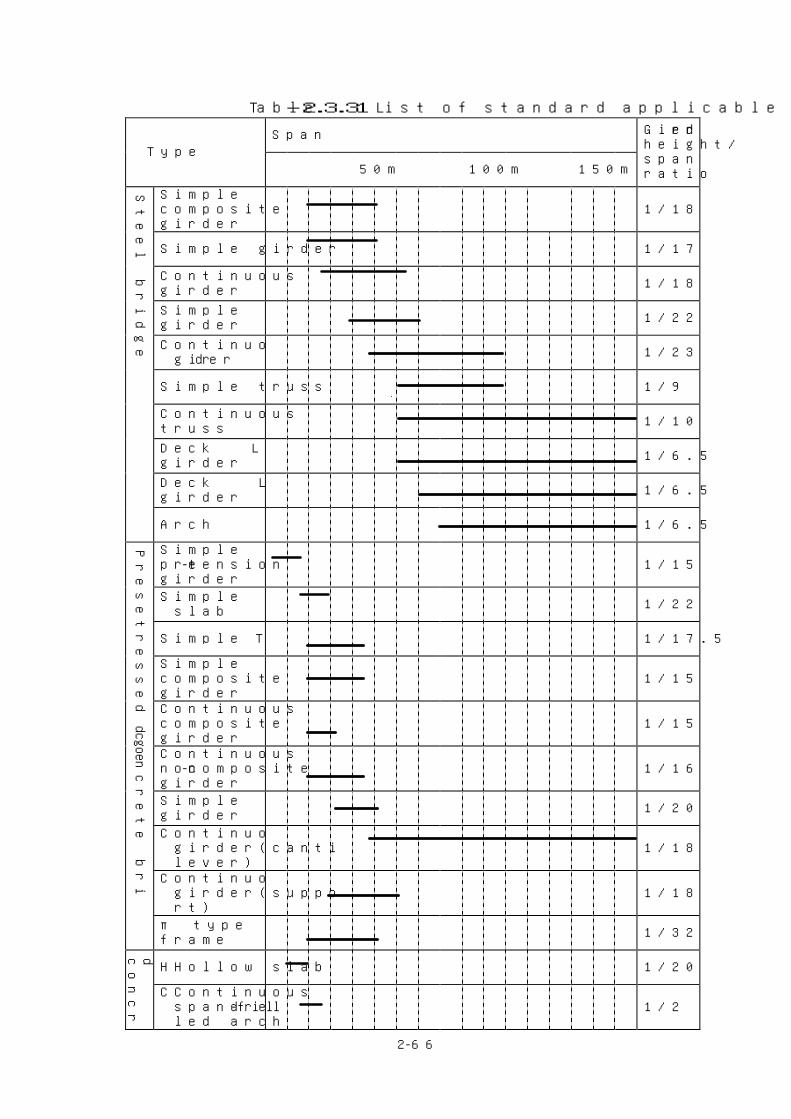
2-66
Table-2.3.31 List of standard applicable span
Span Type
50m 100m 150m
Girder height/span ratio
Simple composite girder
1/18
Simple girder 1/17
Continuous girder 1/18
Simple box girder
1/22
Continuous box girder
1/23
Simple truss
1/9
Continuous truss
1/10
Deck Langer girder
1/6.5
Deck Lohse girder
1/6.5
Steel bridge
Arch
1/6.5
Simple pre-tension girder
1/15
Simple hollow slab 1/22
Simple T girder
1/17.5
Simple composite girder
1/15
Continuous composite girder
1/15
Continuous non-composite girder
1/16
Simple box girder
1/20
Continuous box girder(cantilever)
1/18
Continuous box girder(support)
1/18
Presetressed concrete bridge
π type rigid frame
1/32
HHollow slab 1/20
d concrete
CContinuous spandrel-filled arch
1/2

2-67
(3)Substructure types
The following points are to be taken into account for selection of the substructure
type, particularly, the abutment. ―An abutment front wall is provided so that the bridge axis becomes normal to
the river channel, and the structural plan must ensure that the front wall does not protrude over the river beyond the existing abutment. Due attention must also be paid to provide protection against scouring around the abutment.
―The abutment and pier must of a structure safe against water flow at the high-water level. The appropriate embedded depth must be secured according to the flow velocity and bed soil, with the footing top end embedded to a minimum 2.0 m depth from the river bed.
―Basic abutment type is to be an inverted T type that is most economical. ―Piers must be of the economical type sufficiently safe against scouring.
a) Foundation type
In this study, a boring survey was made at six points for Gampola Bridge and at 12 points for Muwagama Bridge (of which eight are for the existing survey data). In consequence, the following foundation types were selected.
Table-2.3.32 Foundation Type
Gampola Bridge Muwagama Bridge
A1 abutment Spread foundation Pile foundation
P1 abutment Spread foundation Pile foundation
P2 abutment Spread foundation Pile foundation
A2 abutment Pile foundation Pile foundation
For pile types, reinforced concrete piles, prestressed concrete piles, H-steel piles, steel pipe piles, and cast-in-place piles as shown in Table-2.3.33 are considered. The cast-in-place was selected for the following reasons:
・Piles made in Sri Lanka are difficult to use because of the large bridge size ・Relatively long piles are advantageous in terms of workability and economy. ・Easy to work with in the field ・Reliable construction

2-68
A comparison of cast-in-place pilesφ800,φ1000, and φ1200 available for this project was made. Pilesφ1000 in size, as shown in shown in Fig.-2.3.9 were found to be most economical.
Fig.-2.3.9 Work cost ratio by pile size
Table-2.3.33 Features of available pile types
Pile type Pile length application range
Supplier Features
Reinforced concrete piles
5m to about 10m Manufacture possible in Sri Lanka
・As a driving method is to be employed, these piles are generally used in cases with a soft upper stratum and a bearing layer to a depth of about 10 m.
・Used for foundation of small bridges where vertical and horizontal loads are small.
・Attention necessary for damage such as cracks, etc. during driving
・Difficulty in joint treatment ・ Economically advantageous
Prestressed concrete piles About 30m
Import (Thailand, Singapore, Japan)
・As a driving method is considered to be employed, these piles are generally used in cases with a soft upper stratum and a bearing layer to a depth of about 30 m.
・Used for foundation of small bridges where vertical and horizontal loads are small.
・Fewer cracks and less damage during driving because concrete strength is higher than that of reinforced concrete piles.
・Slightly economically advantageous
H steel piles About 30m Import (Thailand, Singapore, Japan)
・Applicable when piles are long because there is no problem in terms of welding joints.
・Normally applied to foundation of temporary structures. ・Prevention of corrosion necessary ・Slightly economically advantageous
Work cost ratio by pile size
0.80
0.90
1.00
1.10
1.20
1.30
φ800 φ1000 φ1200 Pile size
Wor
k co
st r
atio

2-69
Steel pipe piles 15~60m Import (Thailand, Singapore, Japan)
・Applicable when the piles are long because there is no problem in terms of welding joints.
・Used for bridge foundation where vertical and horizontal loads are large.
・Slightly economically disadvantageous
Cast-in-place piles 15~60m
Procurable in Sri Lanka (Possible if the excavation machine is available)
・Applicable when the piles are long because there is no problem in terms of welding joints. Applicable when vertical and horizontal loads are large.
・Used for bridge foundation where vertical and horizontal loads are large.
・Slightly economically inferior
Table-2.3.34 Foundation type selection table
RC
Pile
PH
C P
ile
Ste
el P
ipe
Pile
Fin
al Im
pact
Met
hod
Jet
Stri
ng M
etho
d
Conc
rete
Pla
cing
Met
hod
Fin
al Im
pact
Met
hod
Jet
Stri
ng M
etho
d
Conc
rete
Pla
cing
Met
hod
All
Casi
ng
Reve
rse
Circ
ulat
ion
Dril
l
Eart
h Dr
ill
Cais
son
Type
Pneu
mati
c Ca
isso
n
Open
Cai
sson
△ ○ ○ ○ ○ ○ ○ ○ ○ ○ ○ ○ × × ○ ○ ○ ○○ × △ ○ ○ ○ ○ ○ ○ ○ △ ○ △ ○ ○ △ △ ○
Gravel Size 5cm or less ○ △ △ ○ ○ ○ ○ ○ ○ ○ ○ ○ ○ ○ ○ ○ ○ ○Gravel Size 5cm~10cm ○ × △ △ △ △ △ △ △ △ ○ ○ △ ○ ○ ○ △ ○Gravel Size 10cm~50cm ○ × × △ × × × × × × △ × × ○ ○ △ × △
△ △ ○ ○ ○ ○ ○ ○ ○ ○ ○ ○ ○ ○ ○ ○ ○ ○Less than 5m ○ × × × × × × × × × × × × ○ × × × ×5~15m △ ○ ○ ○ ○ ○ ○ ○ ○ ○ ○ △ ○ ○ ○ ○ △ △15~25m × △ ○ ○ ○ ○ ○ ○ ○ ○ ○ ○ ○ ○ ○ ○ ○ ○25~40m × × ○ ○ ○ ○ ○ ○ ○ ○ ○ ○ △ △ ○ ○ ○ ○40~60m × × △ ○ △ △ △ ○ ○ ○ △ ○ × × △ ○ ○ ○More than 60m × × × △ × × × × × × × △ × × × △ △ △Clayey Soil (20≦N) ○ ○ ○ ○ ○ × △ ○ × △ ○ ○ ○ ○ ○ ○ ○ ○Sand, Gravel(30≦N) ○ ○ ○ ○ ○ ○ × ○ ○ × ○ ○ ○ ○ ○ ○ ○ ○
○ × △ ○ △ △ △ ○ ○ ○ ○ △ △ ○ ○ △ △ △○ △ △ ○ △ △ △ ○ △ △ ○ ○ ○ ○ ○ △ △ ○△ ○ ○ ○ ○ ○ ○ ○ ○ ○ ○ ○ △ △ ○ ○ ○ ○△ ○ ○ ○ ○ ○ ○ ○ ○ ○ ○ ○ △ × ○ ○ ○ △× ○ ○ ○ × × × × × × × × × × △ △ ○ ×× ○ ○ ○ ○ × × ○ × × × × × × ○ △ ○ ×○ ○ ○ ○ ○ ○ ○ ○ ○ ○ ○ ○ ○ ○ × △ × ×○ △ ○ ○ ○ ○ ○ ○ ○ ○ ○ ○ ○ ○ ○ ○ ○ ○○ × △ ○ △ △ △ ○ ○ ○ ○ ○ △ ○ ○ ○ ○ ○○ ○ ○ ○ ○ ○ ○ ○ ○ ○ ○ ○ ○ ○ △ △ △ △○ × △ ○ △ △ △ ○ ○ ○ ○ ○ ○ ○ ○ ○ ○ ○
○ ○ ○ ○ ○ ○ ○ ○ ○ ○ ○ ○ ○○ ○ ○ ○ ○ ○
○ ○ ○ ○ △ △ △ △ △ △ × ○ △ × △ △ ○ ×× △ △ ○ △ △ △ △ △ △ × △ × × △ △ ○ ×○ △ △ △ △ △ △ △ △ △ △ △ △ ○ △ △ × △
△ ○ ○ × × × △ △ △ △ × × ×△ ○ ○ ○ ○ ○ ○ ○ ○ ○ ○ ○ ○ × × ○ ○ ○○ × × × △ ○ ○ △ ○ ○ △ ○ ○ ○ ○ ○ △ ○○ × × △ △ ○ ○ △ ○ ○ ○ ○ ○ △ △ △ △ ○
○:Highly Applicable △:Applicable ×:Less Applicable
Structural
Characteristics
Work Conditions
PHC Pile
Conditions of the Bearing
Layer
Conditions above
Bearing Layer
Ground Conditions
Depth of Bearing
Layer
Nature ofBearing
Layer Soil
Type ofSupport
Work AboveWater
Load Size
Groundwater
Condition
Effects on Neighboring Structures
Narrow Working Space
Batter Pile
Effects of Harmful Gas
Environment
Friction Pile
Water Depth less than 5m
Water Depth 5m or more
Anti-vibration / Anti-noise Measures
Large Vertical Load (Span 50m or more)
Horizontal Load Comparatively Smaller than Vertical
Horizontal Load Comparatively Larger than Vertical
Bearing Pile
Confined Groundwater at 2 m or more from surface
Groundwater flow of 3m/min or more
Small Vertical Load (Span 20m or Less)
Normal Vertical Load (Span 20m~50m)
Large Dip (More than 30 degree)
Excessive Irregularities of Bearing Layer Surface
Groundwater Levels near surface
Extremely Large Amount of Inflow Water
Extremely Soft Layer in Intermediate Stratum
Extremely Hard Layer in Intermediate Stratum
Ground that would Liquefy Exists
Gravel in theIntermediateStratum
Type of Foudaton
Conditions
Ste
elP
ipe
She
etP
ileF
ound
atio
n
Diaphragm
FoundationDriving Pile
Foundation
Spr
ead
Fou
ndat
ion Steel Pipe Pile
Pile Foundation by Inner Excavation Cast-in-place PileFoundation
CaissonFoundation

2-70
(4) Selection of the bridge type
The comparison table of bridge tables is shown in subsequent pages. In consequence, the following bridge types were selected: ①Gampola Bridge:Three-span post-tensioned connection girder bridge Reason:Economically superior. Easy to maintain ②Muwagama Bridge:Single-span Trussed Langer bridge Reason:No economical difference, but the shortest in work
period.
Not susceptible to effects of wet season Not susceptible to scouring of river bed
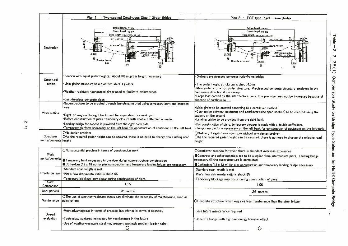


CHAPTER 4

4-1
Chapter 4 Project Evaluation and Recommendation
4-1 Project Effects
This project aims at economic development and improvement of people’s livelihoods
in regional society along the road including bridges. The project also involves reconstruction of heavily damaged bridges to prevent physical damage and injury to personnel due to the bridge falling and to avoid stagnation of regional social activities and administrative functions incurred by associated traffic shutdowns.
The area covered by this project has facilities necessary for daily life. Considering the current bridge conditions, such as deterioration and blockage of traffic by oncoming traffic, etc., however, urgent rehabilitation is necessary. There is a great expectation of grant-aid for development of social infrastructures. Concerning both bridges, it is either impossible or extremely difficult to use another route.
Effects of this project are listed in the table below.

4-2
Table-4.1.1 Effects of this project
Present state and problems Countermeasures Effects and degree of improvement
① Danger of bridge falling due to scouring of piers and deterioration of the bridge
① Replacement with a new bridge with a structure highly resistant to floods by raising the road and embedment of abutment/piers for protection of approach slope.
①Assurance of traffic throughout the year around and improvement of traveling quality, which is expected to contribute to stabilization of people’s livelihoods, such as securing medical service and public order in case of emergency
② Bridges covered by project are not durable under heavy traffic and not wide enough to allow smooth running of large industrial trucks.
② Rehabilitation to assure traffic of heavy vehicles including large trucks.
②The road will fully function as a national road to contribute to economic development of the region and the country.
③ The bridge width and number of lanes not complying with the Sri Lank standard make travel in opposite directions impossible on the bridge, causing traffic bottlenecks.
④ The sidewalk is narrow and
heavily damaged, causing mixed traffic of pedestrians, bicycles, and vehicles, resulting in safety problems.
③ Rehabilitation to create bridge width and number of lanes complying with the Sri Lanka standard to cope with current conditions.
④ Separation of the sidewalk and
roadway according to traffic volume to secure traffic safety.
③Appropriate bridge width and number of lanes for current conditions will enable smooth traffic flow.
④ Enhanced safety through
separation of sidewalk and roadway.
⑤ The river water level rises in the rainy season. Some bridges cannot ensure clearance for maximum water level.
⑤ Create appropriate clearance to eliminate possibility of flooding.
⑤Securing of sufficient flow capacity of the river to prevent traffic failure caused by road flooded with river water, thereby contributing to stabilization of the society and economy.
The population to benefit from the project is about 4 million, including the Central Province (about 2.3 million) where the Gampola Bridge is located and the Sabaragamuwa Province (about 1.7 million) where the Muwagama Bridge is located Projects of other donors do not interfere with this project, and project implementation based on grant-aid is judged to be appropriate. After consideration of the Sri Lanka’s capacity for maintenance and operation of this project, implementation based on grant-aid is considered appropriate.
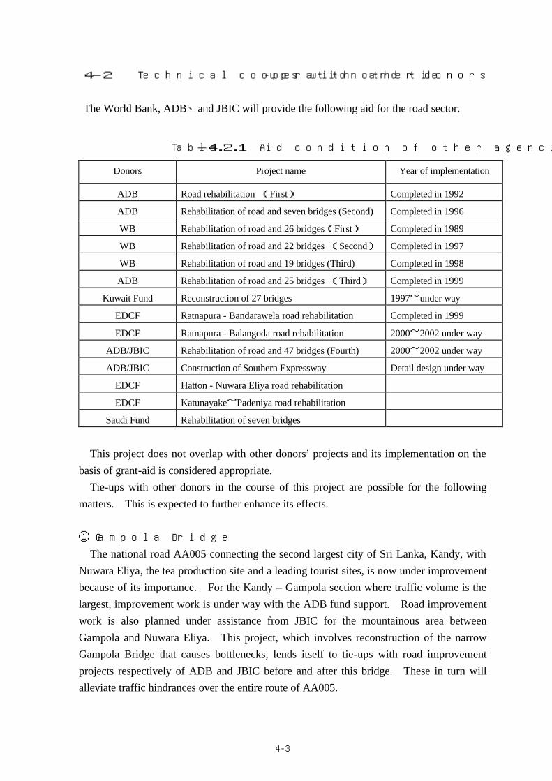
4-3
4-2 Technical cooperation and tie-ups with other donors
The World Bank, ADB、and JBIC will provide the following aid for the road sector.
Table-4.2.1 Aid condition of other agencies
Donors Project name Year of implementation
ADB Road rehabilitation (First) Completed in 1992
ADB Rehabilitation of road and seven bridges (Second) Completed in 1996
WB Rehabilitation of road and 26 bridges(First) Completed in 1989
WB Rehabilitation of road and 22 bridges (Second) Completed in 1997
WB Rehabilitation of road and 19 bridges (Third) Completed in 1998
ADB Rehabilitation of road and 25 bridges (Third) Completed in 1999
Kuwait Fund Reconstruction of 27 bridges 1997~under way
EDCF Ratnapura - Bandarawela road rehabilitation Completed in 1999
EDCF Ratnapura - Balangoda road rehabilitation 2000~2002 under way
ADB/JBIC Rehabilitation of road and 47 bridges (Fourth) 2000~2002 under way
ADB/JBIC Construction of Southern Expressway Detail design under way
EDCF Hatton - Nuwara Eliya road rehabilitation
EDCF Katunayake~Padeniya road rehabilitation
Saudi Fund Rehabilitation of seven bridges
This project does not overlap with other donors’ projects and its implementation on the
basis of grant-aid is considered appropriate. Tie-ups with other donors in the course of this project are possible for the following
matters. This is expected to further enhance its effects.
① Gampola Bridge
The national road AA005 connecting the second largest city of Sri Lanka, Kandy, with Nuwara Eliya, the tea production site and a leading tourist sites, is now under improvement because of its importance. For the Kandy – Gampola section where traffic volume is the largest, improvement work is under way with the ADB fund support. Road improvement work is also planned under assistance from JBIC for the mountainous area between Gampola and Nuwara Eliya. This project, which involves reconstruction of the narrow Gampola Bridge that causes bottlenecks, lends itself to tie-ups with road improvement projects respectively of ADB and JBIC before and after this bridge. These in turn will alleviate traffic hindrances over the entire route of AA005.

4-4
② Muwagama Bridge
The B390 road branches from A4 in the approximate center of Ratnapura, passes through the Muwagama area divided by the Kalu River, and connects to Palawela, Karawita.
Because of the short distance to the center of Ratnapura, Muwagama and areas on opposite banks of the Kalu River are now commutable areas and serve more and more as commuter towns along with the development of the central area of Ratnapura. In line with this situation, the traffic through the Muwagawa Bridge has increased substantially due to the increase in commuters in addition to the conventional traffic for tea transport.
This project involves reconstruction of the Muwagama Bridge that now is a hindrance to traffic to and from the Muwagama area and the central area of Ratnapura because of its narrowness. The project will eliminate congestion along B390 while supporting the Ratnapura City Development project through tie-ups. Moreover, tie-up with the ADB’s road network improvement project for development and improvement of the A4 section between Colombo and Ratnapura and with an EDCF project (supported by Korean loan) for development and improvement of the section from Ratnapura toward Balangoda, Central Province will facilitate communication between cities. This will effectively contribute to networking for smooth exchanges of personnel and goods.
4-3 Recommendation
As described above, implementation of this project will offer considerable effects and contribute greatly to social and economic development in the surrounding areas. Therefore, the appropriateness of implementing this project on the basis of grant-aid can be confirmed. In addition, the Sri Lanka capacity in terms of personnel and funds is considered sufficient and without any problem for operation and administration of this project. Note however that re-coating every 10 years must be made without fail for the Muwagama Bridge.
Review of the budgetary measures of RDA, an implementing agency of the Sri Lanka Government, and the technical and operational capability of divisions in charge showed that implementation on the basis of grant-aid is appropriate.

DRAWINGS


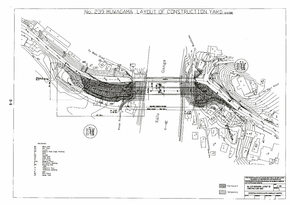

Appendices

Appendices
1.Member List of the Survey Team 2.Survey Schedule 3.List of Party Concerned in the Recipient Country

A-1-1
Appendices : 1. Member List of the Survey Team 1-1. For the First study Mr. Masafumi NAGAISHI
Leader Sri Lanka Office, JICA Assistant Resident Representative
Mr. Kazuo YANAGIDA Chief Consultant / Road Traffic Planner
Oriental Consultants Co., Ltd.
Mr. Mamoru OKUBO Bridge DesignerⅠ
Oriental Consultants Co., Ltd.
Mr. Jiro KOJIMA Bridge DesignerⅡ
Oriental Consultants Co., Ltd.
1-2. For the Second study Mr. Kenji KIYOMIZU
Leader Institute for International Cooperation, JICA Senior Advisor
Mr. Kazuo YANAGIDA Chief Consultant / Road Traffic Planner
Oriental Consultants Co., Ltd.
Mr. Mamoru OKUBO Bridge DesignerⅠ
Oriental Consultants Co., Ltd.
Mr. Jiro KOJIMA Bridge DesignerⅡ
Oriental Consultants Co., Ltd.
Mr. Yoshimitsu YAMADA Natural Conditions SurveyorⅠ
Oriental Consultants Co., Ltd.
Mr. Hitoshi SHIMADA Natural Conditions SurveyorⅡ Oriental Consultants Co., Ltd.
Mr. Masataka FUJIKUMA Construction Planner / Cost Estimator
Oriental Consultants Co., Ltd.
1-3. For Explanation Draft Final Report Mr. Seiji KAIHO
Leader Sri Lanka Office, JICA Resident Representative
Mr. Kazuo YANAGIDA Chief Consultant / Road Traffic Planner
Oriental Consultants Co., Ltd.
Mr. Mamoru OKUBO Bridge DesignerⅠ
Oriental Consultants Co., Ltd.
Mr. Jiro KOJIMA Bridge DesignerⅡ
Oriental Consultants Co., Ltd.

A-2-1
Appendices : 2. Survey Schedule 2-1. Schedule for the First Site Survey No Date Day Stay 1 2 Remark
1 6/22 Thr. Colombo
1200 Narita—1750 Singapore (SNG) (SQ997)
2240 SNG—0005 Colombo (SQ402)
2 23 Fri. Colombo
Courtesy Call to JICA Office, Embassy of Japan, Min. of Transport &Highways, Dept. of External Resources,
Dept. of National Planning and Road Development Authority
3 24 Sat. Colombo Site survey (Bridges No.66 & 154)
4 25 Sun Colombo Site Survey (Bridges No.122 & 158)
5 26 Mon. Colombo Discussion of I/C Report with RDA Officials 6 27 Tue. Colombo Discussion of I/C Report with RDA Officials
7 28 Wed. Nuwara Eliya
Site survey (Bridges No.239)
8 29 Thr. Kandy Site survey (Bridges No.93)
9 30 Fri. Colombo Site survey (Bridges No.157 & 181& 200)
10 7/1 Sat. Hambantota Site survey (Bridges No.67) 11 2 Sun Colombo Site survey (Bridges No.42)
12 3 Mon. Colombo Report of site survey to RDA Officials
13 4 Tue, Colombo Review of Site survey
14 5 Wed. Colombo Review of Site survey
Discussion of answering of Questionnaire with RDA Officials
15 6 Thr. Colombo Review of Site survey 16 7 Fri. Colombo Review of Site survey 17 8 Sat. Colombo Team meeting 18 9 Sun Colombo Team meeting 19 10 Mon. Colombo Discussion of the Minutes with RDA Officials
20 11 Tue, Colombo Signing of the Minutes, Report to JICA Office and Embassy of Japan
21 12 Wed. 0120 Colombo—0710 SNG
(SQ401) 0950 SNG—1735Narita (SQ12)
1. Mr. Masafumi NAGAISHI
Leader Sri Lanka Office, JICA Assistant Resident Representative
2. Mr. Kazuo YANAGIDA
Chief Consultant / Road Traffic Planner
Oriental Consultants Co., Ltd.
Mr. Mamoru OKUBO Bridge DesignerⅠ
Oriental Consultants Co., Ltd.
Mr. Jiro KOJIMA Bridge DesignerⅡ
Oriental Consultants Co., Ltd.
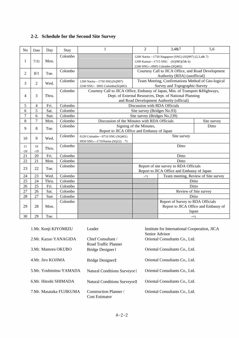
A-2-2
2-2. Schedule for the Second Site Survey
No Date Day Stay 1 2 3,4&7 5,6
1 7/31 Mon. Colombo
1200 Narita—1750 Singapore (SNG) (SQ997) (2,3,4& 7) 1200 Kansai—1715 SNG (SQ985)(5& 6) 2240 SNG—0005 Colombo (SQ402)
2 8/1 Tue. Colombo Courtesy Call to JICA Office, and Road Development Authority (RDA) (unofficial)
3 2 Wed. Colombo 1200 Narita—1750 SNG(SQ997) 2240 SNG―0005 Colombo(SQ402)
Team Meeting, Confirmations Method of Geo-logical Survey and Topographic-Survey
4 3 Thru. Colombo Courtesy Call to JICA Office, Embassy of Japan, Min. of Transport &Highways,
Dept. of External Resources, Dept. of National Planning and Road Development Authority (official)
5 4 Fri. Colombo Discussion with RDA Officials
6 5 Sat. Colombo Site survey (Bridges No.93)
7 6 Sun Colombo Site survey (Bridges No.239)
8 7 Mon. Colombo Discussion of the Minutes with RDA Officials Site survey
9 8 Tue. Colombo Signing of the Minutes, Report to JICA Office and Embassy of Japan
Ditto
10 9 Wed. Colombo 0120 Colombo—0710 SNG (SQ401) 0950 SNG—1735Narita (SQ12) *1
Site survey
11 -20
10 -19
Thru. Colombo Ditto
21 20 Fri. Colombo Ditto 22 21 Mon. Colombo Ditto
23 22 Tue. Colombo Report of site survey to RDA Officials Report to JICA Office and Embassy of Japan
24 23 Wed. Colombo =*1 Team meeting, Review of Site survey 25 24 Thru. Colombo Ditto 26 25 Fri. Colombo Ditto 27 26 Sat. Colombo Review of Site survey
28 27 Sun Colombo Ditto
29 28 Mon. Colombo Report of Survey to RDA Officials
Report to JICA Office and Embassy of Japan
30 29 Tue. =*1
1.Mr. Kenji KIYOMIZU
Leader Institute for International Cooperation, JICA Senior Advisor
2.Mr. Kazuo YANAGIDA Chief Consultant / Road Traffic Planner
Oriental Consultants Co., Ltd.
3.Mr. Mamoru OKUBO Bridge DesignerⅠ
Oriental Consultants Co., Ltd.
4.Mr. Jiro KOJIMA Bridge DesignerⅡ
Oriental Consultants Co., Ltd.
5.Mr. Yoshimitsu YAMADA Natural Conditions SurveyorⅠ
Oriental Consultants Co., Ltd.
6.Mr. Hitoshi SHIMADA Natural Conditions SurveyorⅡ Oriental Consultants Co., Ltd.
7.Mr. Masataka FUJIKUMA Construction Planner / Cost Estimator
Oriental Consultants Co., Ltd.

A-2-3
2-3. Schedule for Explanation Draft Basic Design Report
No Date Day Stay 1 2
1 10/23 Mon. Colombo 1200Narita—1750 SNG (SQ997)
2240 SNG—0005 Colombo (SQ402)
2 24 Tue, Colombo Courtesy Call to JICA Office, Embassy of Japan,
Dept. of External Resources, Dept. of National Planning, Min. of Highways, and Road Development Authority
3 25 Wed. Colombo Explanation of Draft Report at RDA
4 26 Thru. Colombo Explanation of Draft Report at RDA Minutes of Discussion
5 27 Fri. Colombo Site survey (Bridges No.239)
6 28 Sat. Kandy Site survey (Bridges No.93)
7 29 Sun. Colombo Site survey (Bridges No.93)
8 30 Mon. Colombo Discussion of the Minutes with RDA Officials
Signing of Minutes of Discussion Courtesy Call to Embassy of Japan
9 31 Tue,
0120 Colombo—0710 SNG (SQ401) 0950 SNG—1735Narita (SQ12)
1. Mr. Seiji KAIHO
Leader Sri Lanka Office, JICA Resident Representative
2. Mr. Kazuo YANAGIDA Chief Consultant / Road Traffic Planner
Oriental Consultants Co., Ltd.
Mr. Mamoru OKUBO Bridge DesignerⅠ
Oriental Consultants Co., Ltd.
Mr. Jiro KOJIMA Bridge DesignerⅡ
Oriental Consultants Co., Ltd.

A-3-1
Appendices : 3. List of Party Concerned in the Recipient Country
◆ Ministry of Finance & Planning
1. Mr. J. H. J. Jayamaha Director, Japan Division, Department of External Resources
◆ Ministry of Transport & Highways
2. Mr. G. Hewagama Secretary
◆ Ministry of Highways
3. Mr. S. L. Senevirante Secretary
4. Mr. W.A. Karunasena Additional Secretary
◆ Road Development Authority
5. Mr. W. A. Jayasinghe Chairman
6. Dr. G. L. Asoka J. de Silva Director, Engineering Services Division (ESD)
7. Mr. H. M. K. G. C. Bandara Chief Engineer (Planning), Traffic & Planning Office, ESD
8. Mr. D. K. Rphitha Swarna Senior Engineer, BDO, ESD
9. Mr. Gunasena Imaduwa Colombo Additional District S secretary ,
Acquiring Officer & Director LAND
10. Mr. A.M. Jawzi Provincial Director, RDA Central Province
11. Mr. I. K. Baddegawa Executive Engineer, RDA Kandy, Gampola office
12. Mrs. N. Samerasinghe Executive Engineer, RDA Matale office
13. Mr. A. N. Abegsuviya Executive Engineer, RDA Ratunpura office
◆ Peradenia University
14. Dr. J.B.Weerakoon Professor, Pasadena University

Appendices
4.Minutes of Discussion For the First Survey 11th July 2000 For the Second study 8th August 2000 For Explanation Draft Final Report 10th October 2000


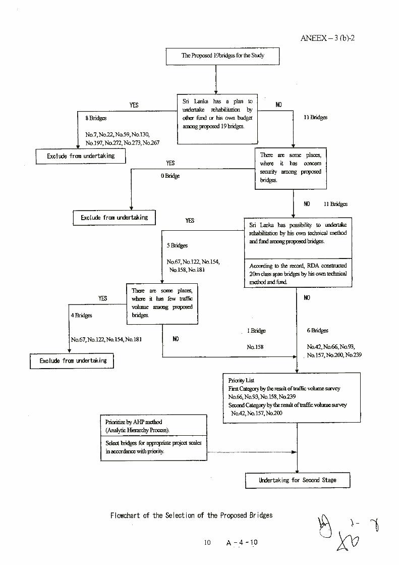


Appendices
5. Other Relevant Data
Technical Memorandum (Second Site Survey 22nd August 2000)
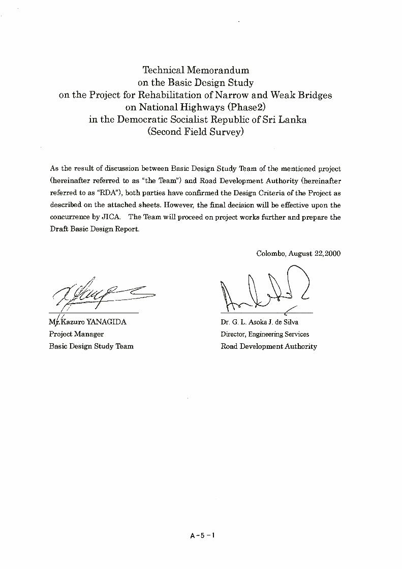

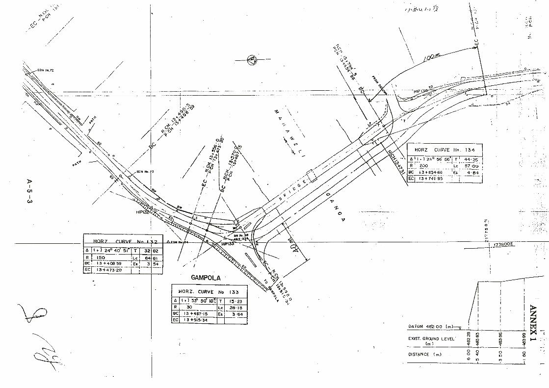


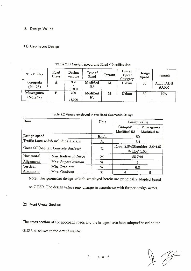


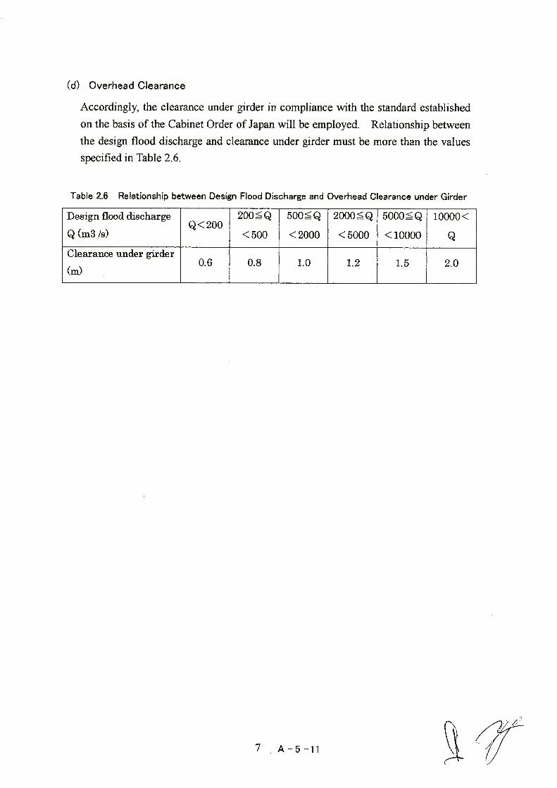


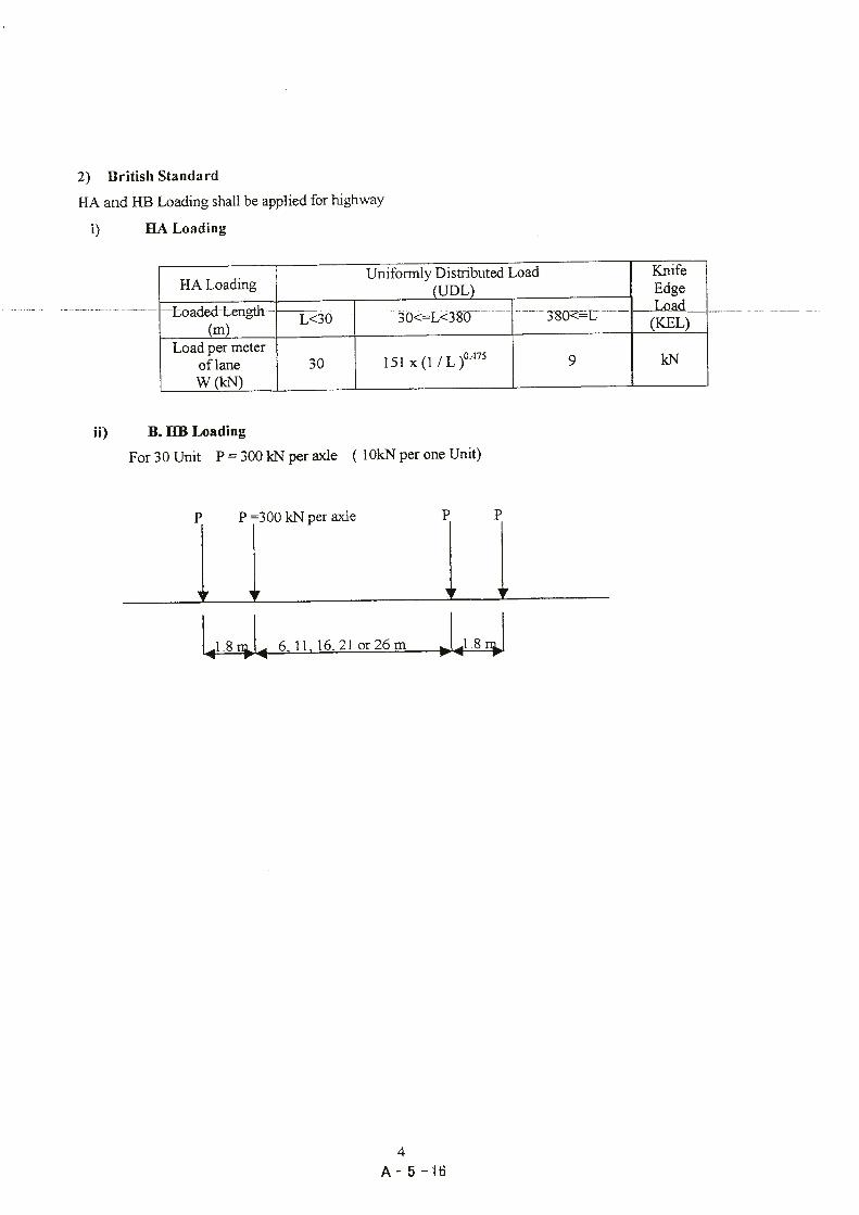


Appendices
6. Other Relevant Data
(Present Condition of the 11Bridges under the First Survey)