
CHAPTER 19 CONCRETE - iccsafe.org · CHAPTER 19 CONCRETE SECTION 1901 GENERAL 1901.1 Scope ......
48
CHAPTER 19 CONCRETE SECTION 1901 GENERAL 1901.1 Scope 1901.1.1 Provisions of this chapter shall govern the mate- rials, design and construction of concrete used in build- ings. Exception: Buildings and structures located within the High Velocity Hurricane Zone shall comply with the provisions of Sections 1917 and 1919 through 1929. 1901.1.2 Structural members of plain and reinforced con- crete, including prestressed concrete, shall be designed and constructed in accordance with the provisions of this chapter and ACI 318. Structural concrete slabs cast on stay-in-place, noncomposite steel form deck shall comply with this chapter and ACI 318. The design of composite concrete on stay-in-place form deck shall comply with ANSYASCE 3. SECTION 1902 DEFINITIONS For definitions, see Chapter 2. SECTION 1903 MATERIALS 1903.1 General. Materials used to produce concrete and admixtures for concrete shall comply with the requirements of this section and ACI 3 18. 1903.2 Cements. Cement shall conform to ASTM C 150, ASTM C 595 or ASTM C 845. Exception: Type S or SA cement manufactured under ASTM C 595 shall not be used as the principal cementi- tious material in structural concrete. 1903.3 Aggregates 1903.3.1 Concrete aggregates shall conform to ASTM C 33 or to ASTM C 330. 1903.3.2 Aggregates failing to meet the standards listed in 1903.3.1, but which have been shown by special test or actual service to produce concrete of adequate strength and durability may be used where authorized by the build- ing official. 1903.3.3 Nominal maximum size of coarse aggregate shall be not larger than: 1. 115 the narrowest dimension between sides of forms, nor 2. 113 the depth of slabs, nor 3. 314 the minimum clear spacing between individual reinforcing bars or wires, bundles of bars, or pre- stressing tendons or ducts. These limitations shall not apply if, in the judgment of the engineer, workability and methods of consolidation are such that concrete can be placed without honeycomb or voids. 1903.4 Water 1903.4.1 Water used in mixing concrete shall be clean and free from injurious amounts of oils, acids, alkalis, salts, organic materials or other substances that may be delete- rious to concrete or reinforcement. 1903.4.2 Mixing water for prestressed concrete or for con- crete that will contain aluminum embedments, including that portion of mixing water contributed in the form of free moisture on aggregates, shall not contain deleterious amounts of chloride ion. See 1904.4. 1903.4.3 Nonpotable water shall not be used in concrete unless specific requirements of ACI 3 18 allowing the use of nonpotable water are satisfied. 1903.5 Steel reinforcement 1903.5.1 Reinforcement shall be deformed reinforcement, except that plain reinforcement shall be permitted for spi- rals or tendons. Reinforcement consisting of structural steel, steel pipe, or steel tubing shall be permitted as spec- ified in ACI 3 18. 1903.5.2 Welding of reinforcing bars shall conform to ANSYAWS Dl .4. The type and location of welded splices and other required welding of reinforcing bars shall be indicated on the design drawings or in the project specifi- cations. ASTM reinforcing bar specifications, except for ASTM A 706, shall be supplemented to require a report of material properties necessary to conform to welding pro- cedures specified in ANSYAWS D 1.4. 1903.5.3 Reinforcement shall conform to the applicable ASTM standards listed in ACI 3 18. 1903.6 Admixtures 1903.6.1 Admixtures to be used in concrete shall comply with ACI 3 18 and be subject to prior approval by the engi- neer. 1903.6.2 An admixture shall be shown capable of main- taining essentially the same composition and performance throughout the work as the product used in establishing concrete proportions in accordance with 1905.2. 1903.6.3 Calcium chloride or admixtures containing chlo- ride from other than impurities from admixture ingredi- ents shall not be used in prestressed concrete, in concrete containing embedded aluminum or in concrete cast against stay-in-place galvanized steel forms. See 1904.3 and 1904.4. FLORIDA BUILDING CODE - BUILDING
Transcript of CHAPTER 19 CONCRETE - iccsafe.org · CHAPTER 19 CONCRETE SECTION 1901 GENERAL 1901.1 Scope ......
CHAPTER 19 CONCRETE
SECTION 1901 GENERAL
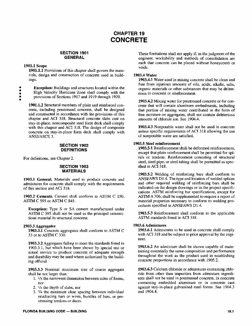
1901.1 Scope 1901.1.1 Provisions of this chapter shall govern the mate- rials, design and construction of concrete used in build- ings.
Exception: Buildings and structures located within the High Velocity Hurricane Zone shall comply with the provisions of Sections 1917 and 1919 through 1929.
1901.1.2 Structural members of plain and reinforced con- crete, including prestressed concrete, shall be designed and constructed in accordance with the provisions of this chapter and ACI 318. Structural concrete slabs cast on stay-in-place, noncomposite steel form deck shall comply with this chapter and ACI 318. The design of composite concrete on stay-in-place form deck shall comply with ANSYASCE 3.
SECTION 1902 DEFINITIONS
For definitions, see Chapter 2.
SECTION 1903 MATERIALS
1903.1 General. Materials used to produce concrete and admixtures for concrete shall comply with the requirements of this section and ACI 3 18.
1903.2 Cements. Cement shall conform to ASTM C 150, ASTM C 595 or ASTM C 845.
Exception: Type S or SA cement manufactured under ASTM C 595 shall not be used as the principal cementi- tious material in structural concrete.
1903.3 Aggregates 1903.3.1 Concrete aggregates shall conform to ASTM C 33 or to ASTM C 330.
1903.3.2 Aggregates failing to meet the standards listed in 1903.3.1, but which have been shown by special test or actual service to produce concrete of adequate strength and durability may be used where authorized by the build- ing official.
1903.3.3 Nominal maximum size of coarse aggregate shall be not larger than:
1. 115 the narrowest dimension between sides of forms, nor
2. 113 the depth of slabs, nor 3. 314 the minimum clear spacing between individual
reinforcing bars or wires, bundles of bars, or pre- stressing tendons or ducts.
These limitations shall not apply if, in the judgment of the engineer, workability and methods of consolidation are such that concrete can be placed without honeycomb or voids.
1903.4 Water 1903.4.1 Water used in mixing concrete shall be clean and free from injurious amounts of oils, acids, alkalis, salts, organic materials or other substances that may be delete- rious to concrete or reinforcement.
1903.4.2 Mixing water for prestressed concrete or for con- crete that will contain aluminum embedments, including that portion of mixing water contributed in the form of free moisture on aggregates, shall not contain deleterious amounts of chloride ion. See 1904.4.
1903.4.3 Nonpotable water shall not be used in concrete unless specific requirements of ACI 3 18 allowing the use of nonpotable water are satisfied.
1903.5 Steel reinforcement 1903.5.1 Reinforcement shall be deformed reinforcement, except that plain reinforcement shall be permitted for spi- rals or tendons. Reinforcement consisting of structural steel, steel pipe, or steel tubing shall be permitted as spec- ified in ACI 3 18.
1903.5.2 Welding of reinforcing bars shall conform to ANSYAWS Dl .4. The type and location of welded splices and other required welding of reinforcing bars shall be indicated on the design drawings or in the project specifi- cations. ASTM reinforcing bar specifications, except for ASTM A 706, shall be supplemented to require a report of material properties necessary to conform to welding pro- cedures specified in ANSYAWS D 1.4.
1903.5.3 Reinforcement shall conform to the applicable ASTM standards listed in ACI 3 18.
1903.6 Admixtures 1903.6.1 Admixtures to be used in concrete shall comply with ACI 3 18 and be subject to prior approval by the engi- neer.
1903.6.2 An admixture shall be shown capable of main- taining essentially the same composition and performance throughout the work as the product used in establishing concrete proportions in accordance with 1905.2.
1903.6.3 Calcium chloride or admixtures containing chlo- ride from other than impurities from admixture ingredi- ents shall not be used in prestressed concrete, in concrete containing embedded aluminum or in concrete cast against stay-in-place galvanized steel forms. See 1904.3 and 1904.4.
FLORIDA BUILDING CODE - BUILDING

1903.6.4 Air-entraining admixtures, water-reducing admixtures, retarding admixtures, accelerating admix- tures, water-reducing and retarding admixtures and water- reducing and accelerating admixtures shall conform to the applicable ASTM standards listed in ACI 3 18.
1903.6.5 Fly ash or other pozzolans used as admixtures shall conform to ASTM C 618. The building official shall require certification of all fly ash materials used in con- crete as conforming to the ASTM C 618 specification.
1903.6.6 Ground granulated blast furnace slag used as an admixture shall conform to ASTM C 989.
1903.7 Storage of materials 1903.7.1 Cementitious materials and aggregate shall be stored in manner that prevents deterioration or intrusion of foreign matter.
1903.7.2 Any material that has deteriorated or has been contaminated shall not be used for concrete.
1903.8 Tests of materials 1903.8.1 The building official shall have the right to order testing of any materials used in concrete construction to determine whether they are of the quality specified.
1903.8.2 Materials and concrete shall be tested in accor- dance with ASTM standards listed in ACI 318. Laboratories conducting tests on concrete and concrete aggregates for use in construction shall comply with ASTM C 1077 except Section 7.4.
1903.8.3 A complete record of tests of materials and of concrete shall be available for inspection during progress of work and for 2 years after completion of the project and shall be preserved by the inspecting engineer or architect for that purpose.
SECTION 1904 DURABILITY REQUIREMENTS
1904.1 Water-Cementitious materials ratio 1904.1.1 Cementitious materials. For purposes of this section, a cementitious material is one specified in 1903 which has cementing value when used in concrete either by itself, such as portland cement, blended hydraulic cements or expansive cement, or when used in combina- tion with fly ash, other raw or calcined natural pozzolans, silica fume and/or ground granulated blast furnace slag.
1904.1.2 Calculation of water-cementitious materials ratio. The water-cementitious materials ratio requirement of Tables 1904B and 1904D shall be calculated using the weight of cement meeting ASTM C 150, ASTM C 595, or ASTM C 845 plus the weight of fly ash and other poz- zolans meeting ASTM C 61 8, ground granulated blast fur- nace slag meeting ASTM C 989 and silica fume meeting ASTM C 1240, if any, except that if concrete is exposed to deicing chemicals, the limits of 1904.2.3 for the amount
of fly ash, pozzolans, silica fume, ground granulated blast furnace slag or the combination of these materials shall be met.
1904.2 Freezing and thawing exposures 1904.2.1 Air-entraining. Normal weight and lightweight concrete exposed to freezing and thawing or deicer chem- icals shall be air-entrained with air content indicated in Table 1904A. Tolerance on air content as delivered shall be + 1.5%. For specified compressive strength, f ', greater than 5,000 psi (34.5 MPa), air content indicated in Table 1904A may be reduced 1 %.
When finely divided materials of fly ash or natural poz- zolans are used as mineral admixtures (see 1903.6.5) in air-entrained portland cement concrete, the building offi- cial shall require air content tests to be made in accor- dance with ASTM C 231 to assure compliance with air content requirements of Table 1904A.
1904.2.2 Low water-permeability. Concrete that is intended to have low permeability to water or concrete that will be subject to freezing and thawing in a moist con- dition, or will be exposed to deicing salts, brackish water, sea water or spray from these sources shall conform to requirements of Table 1904B.
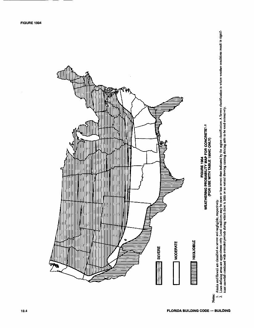
Exception: Normal weight aggregate concrete used in buildings or their appurtenances of Group R occupan- cies three stories or less in height, and subject to weath- ering (i.e., freezing and thawing) as determined from Figure 1904 or deicer chemicals, shall comply with the requirements of Table 1904C.
In addition, concrete that will be exposed to deicing chem- icals shall conform to the limitations of 1904.2.3.
1904.2.3 Limitations on use of certain cementitious materials. For concrete exposed to deicing chemicals, the maximum weight of fly ash, other pozzolans, silica fume or ground granulated blast furnace slag that is included in the concrete shall not exceed the percentages of the total weight of cementitious materials specified in Table 1904F.
1904.3 Exposure to sulfate-containing solutions. Concrete to be exposed to sulfate-containing solutions shall conform to the requirements of Table 1904D or be made with a cement that provides sulfate resistance and used in concrete with a maximum water-cementitious materials ratio or minimum specified compressive strength from Table 1904D. Calcium chloride as an admixture shall not be used in concrete to be exposed to severe or very severe sulfate containing solutions, as defined in Table 1904D.
1904.4 Water soluble chloride ion content. For corrosion protection of reinforcement in concrete, maximum water sol- uble chloride ion concentrations in hardened concrete at ages from 28 to 42 days contributed from the ingredients includ- ing water, aggregates, cementitious materials and admixtures shall not exceed the limits of Table 1904E. ~ests-performed
FLORIDA BUILDING CODE - BUILDING
1904.5 - TABLE 1904C
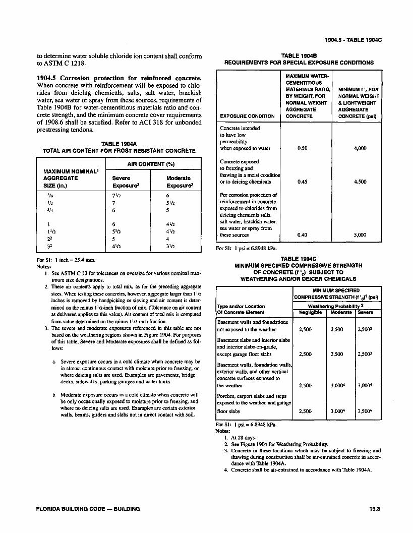
to determine water soluble chloride ion content shall conform TABLE 19048 to ASTM C 1218. REQUIREMENTS FOR SPECIAL EXPOSURE CONDITIONS
1904.5 Corrosion protection for reinforced concrete. When concrete with reinforcement will be exposed to chlo- rides from deicing chemicals, salts, salt water, braclush water, sea water or spray from these sources, requirements of Table 1904B for water-cementitious materials ratio and con- crete strength, and the minimum concrete cover requirements of 1908.6 shall be satisfied. Refer to ACI 3 18 for unbonded prestressing tendons.
TABLE 1904A TOTAL AIR CONTENT FOR FROST RESISTANT CONCRETE
For SI: 1 inch = 25.4 mm. Notes:
1. See ASTM C 33 for tolerances on oversize for various nominal max- imum size designations.
2. These air contents apply to total mix, as for the preceding aggregate sizes. When testing these concretes, however, aggregate larger than 1 '12 inches is removed by handpicking or sieving and air content is deter- mined on the minus 1112-inch fraction of mix. (Tolerance on air content as delivered applies to this value). Air content of total mix is computed from value determined on the minus 1 112-inch fraction.
MAXIMUM NOMINAL1 AGGREGATE SIZE (In.)
318 '12 314
1 1 '12 22 9
3. The severe and moderate exposures referenced in this table are not based on the weathering regions shown in Figure 1904. For purposes of this table, Severe and Moderate exposures shall be defined as fol- lows:
AIR CONTENT (%)
a. Severe exposure occurs in a cold climate when concrete may be in almost continuous contact with moisture prior to freezing, or where deicing salts are used. Examples are pavements, bridge decks, sidewalks, parking garages and water tanks.
Severe Exposures
7112 7 6
6 5 'I2 5 4%
b. Moderate exposure occurs in a cold climate when concrete will be only occasionally exposed to moisture prior to freezing, and where no deicing salts are used. Examples are certain exterior walls, beams, girders and slabs not in direct contact with soil.
Moderate Exposures
6 5'12 5
4112 4112 4 3Il2 For SI: 1 psi = 6.8948 kPa.
TABLE 1904C MINIMUM SPECIFIED COMPRESSIVE STRENGTH
OF CONCRETE (f '3 SUBJECT TO WEATHERING AND/OR DEICER CHEMICALS
EXPOSURE CONDITION
Concrete intended to have low permeability when exposed to water
Concrete exposed to freezing and thawing in a moist conditior or to deicing chemicals
For corrosion protection of reinforcement in concrete exposed to chlorides from deicing chemicals salts, salt water, brackish water, sea water or spray from
. these sources
For SI: 1 psi = 6.8948 P a . Notes:
1. At 28 days. 2. See Figure 1904 for Weathering Probability. 3. Concrete in these locations which may be subject to freezing and
thawing during construction shall be air-entrained concrete in accor- dance with Table 1904A.
4. Concrete shall be air-entrained in accordance with Table 1904A.
MAXIMUM WATER- CEMENTmOUS MATERIALS RATIO. BY WEIGHT, FOR NORMAL WEIGHT AGGREGATE CONCRETE
0.50
0.45
0.40 I
Type and/or Locatlon M Concrete Element
Basement walls and foundations not exposed to the weather
Basement slabs and interior slabs and interior slabs-on-grade, except garage floor slabs
Basement walls, foundation walls, exterior walls, and other vertical concrete surfaces exposed to the weather
Porches, carport slabs and steps exposed to the weather, and garage
floor slabs
FLORIDA BUILDING CODE - BUILDING
MINIMUM 1 ',FOR NORMAL WEIGHT & LIGHTWEIGHT AGGREGATE CONCRETE (psi)
4,000
4,500
5,000
MINIMUM SPECIFIED COMPRESSIVE STRENGTH (1 ',.)I (psi)
Weathering Probability 2 Negllglble
2,500
2,500
2,500
2,500
Moderate
2,500
2,500
3,0004
3,0004
Severe
2,5003
2,5003
3,0004
3,5004
Not
es:
1. 2.A
lask
a an
d H
awai
i ar
e cl
assi
fied
as
seve
re a
nd n
eglig
ible
, re
spec
tivel
y.L
ines
def
inin
g ar
eas
are
appr
oxim
ate
only
. L
ocal
con
ditio
ns m
ay b
e m
ore
or le
ss s
ever
e th
an in
dica
ted
by t
he re
gio
n cl
assi
fica
tion.
A S
ever
e cl
assi
fica
tion
is w
here
wea
ther
con
ditio
ns re
sult
in s
igni
f-ic
ant s
now
fall
com
bine
d w
ith e
xten
ded
peri
ods
duri
ng w
hich
the
re is
litt
le o
r no
nat
ural
thaw
ing
caus
ing
deic
ing
salts
to
be u
sed
exte
nsiv
ely.
SE
VE
RE
MO
DE
RA
TE
NE
GLI
GIB
LE

TABLE 1904D - TABLE 1904F
TABLE 1904D REQUIREMENTS FOR CONCRETE EXPOSED TO SULFATECONTAINING SOILS OR WATER
For SI: 1 psi = 6.8948 kPa. Notes:
1. A lower water-cementitious material ratio or higher strength may be required for low permeability or for protection against corrosion of embedded items or freezing and thawing (Table 1904B).
2. Sea water. 3. Pozzolan that has been determined by test or service record to improve sulfate resistance when used in concrete containing 'I).pe V cement.
SULFATE EXPOSURE
Negligible
ModerateZ
Severe
very severe
TABLE 1904E MAXIMUM CHLORIDE ION CONTENT
FOR CORROSION PROTECTION OF REINFORCEMENT
WATER SOLUBLE SULFATE (SO,) IN SOIL (% by welght)
0.00-0.10
0.10-0.20
0.20-2.00
Over 2.00
TABLE 1904F REQUIREMENTS FOR CONCRETE EXPOSED
TO DEICING CHEMICALS
TYPE OF MEMBER
Prestressed wnaete Reinforced concrete exposed
to chloride in service Reinforced concrete that
will be dry or protected from moisture in service
Other reinforced concrete construction
SULFATE (SO,) IN WATER ( P P ~ )
0- 150
150-1,500
1,500-10,000
Over 10,000
MAXIMUM WATER SOLUBLE CHLORIDE ION ( ~ 1 3 IN CONCRETE (% by welght of wmont)
0.06
0.15
1.00
0.30
Notes: 1. The total cementitious material also includes ASTM C 150, ASTM C
595 and ASTM C 845 cement. The maximum percentages above shall include:
a. Fly ash or other pozzolans present in Type IP or I(PM) blend- ed cement.
b. Ground granulated blast furnace slag used in the manufacture of a 'Qp IS or I(SM) blended cement
c. Silica fume present in a blended cement 2. Fly ash or other pozzolans and silica fume shall constitute no more
than 25 and 10 percent, respectively, of the t o y weight of the cemen- titious materials.
CEMENTmOUS MATERIALS
Fly ash or other pozzolans conforming toASTh4 C618
Ground granulated blast furnace slag conforming to ASTM C 989
Silica Fume conforming to ASTh4 C 1240 Total of fly ash or other pouolans, ground
granulated blast funrace slag and silica fume Total of fly ash or other pozzolans and
silica fume
FLORIDA BUILDING CODE - BUILDING
MAXIMUM PERCENTAGE OF TOTAL CEMENTITIOUS MATERIALS BY WEIGHT
25
50 10
502
352
CEMENT TYPE
MAXIMUM WATER- CEMENTrt'lOUS MATERIALS RATIO, BY WEIGHT, FOR NORMAL WEIGHT AGGREGATE CONCRETE1
-
0.50
0.45
0.45
ASTM C 150
-
I1
V
V plus pozzolan3
MIN. t ', FOR NORMAL WEIGHT AND LIGHTWEIGHT AGGREGATE CONCRETE (PI)' -
4,000
4.500
4,500
ASTM C 595
-
IP (MS), IS (MS), P (MS), I (PM) (MS), I (SM) (MS)
-
-
1905 - TABLE 1905.3A
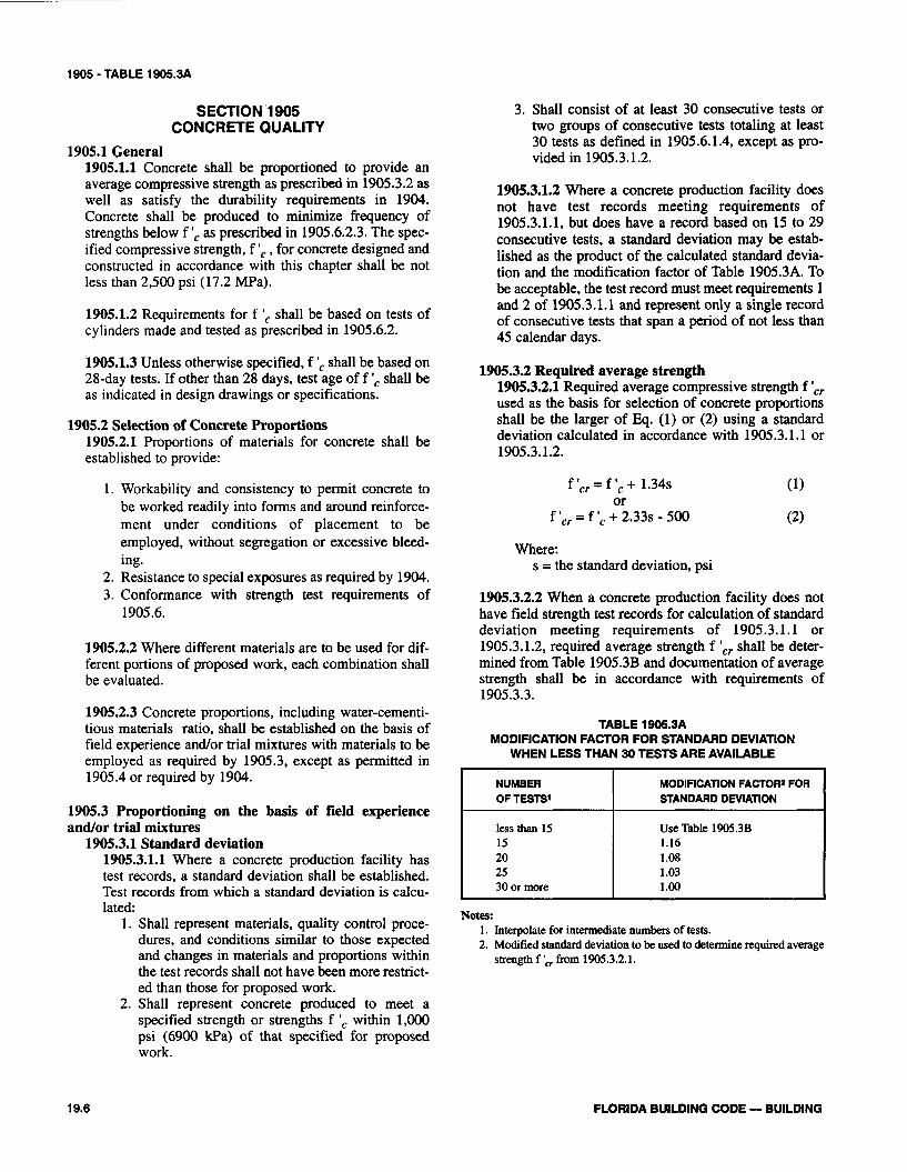
SECTION 1905 CONCRETE QUALITY
1905.1 General 1905.1.1 Concrete shall be proportioned to provide an average compressive strength as prescribed in 1905.3.2 as well as satisfy the durability requirements in 1904. Concrete shall be produced to minimize frequency of strengths below f ', as prescribed in 1905.6.2.3. The spec- ified compressive strength, f ', , for concrete designed and constructed in accordance with this chapter shall be not less than 2,500 psi (17.2 MPa).
1905.1.2 Requirements for f ', shall be based on tests of cylinders made and tested as prescribed in 1905.6.2.
1905.1.3 Unless otherwise specified, f ', shall be based on 28-day tests. If other than 28 days, test age of f ', shall be as indicated in design drawings or specifications.
1905.2 Selection of Concrete Proportions 1905.2.1 Proportions of materials for concrete shall be established to provide:
1 . Workability and consistency to permit concrete to be worked readily into forms and around reinforce- ment under conditions of placement to be employed, without segregation or excessive bleed- ing.
2. Resistance to special exposures as required by 1904. 3. Conformance with strength test requirements of
1905.6.
1905.2.2 Where different materials are to be used for dif- ferent portions of proposed work, each combination shall be evaluated.
1905.2.3 Concrete proportions, including water-cementi- tious materials ratio, shall be established on the basis of field experience andlor trial mixtures with materials to be employed as required by 1905.3, except as permitted in 1905.4 or required by 1904.
1905.3 Proportioning on the basis of field experience andfor trial mixtures
1905.3.1 Standard deviation 1905.3.1.1 Where a concrete production facility has test records, a standard deviation shall be established. Test records from which a standard deviation is calcu- lated:
1. Shall represent materials, quality control proce- dures, and conditions similar to those expected and changes in materials and proportions within the test records shall not have been more restrict- ed than those for proposed work.
2. Shall represent concrete produced to meet a specified strength or strengths f ', within 1,000 psi (6900 kPa) of that specified for proposed work.
3. Shall consist of at least 30 consecutive tests or two groups of consecutive tests totaling at least 30 tests as defined in 1905.6.1.4, except as pro- vided in 1905.3.1.2.
1905.3.1.2 Where a concrete production facility does not have test records meeting requirements of 1905.3.1.1, but does have a record based on 15 to 29 consecutive tests, a standard deviation may be estab- lished as the product of the calculated standard devia- tion and the modification factor of Table 1905.3A. To be acceptable, the test record must meet requirements 1 and 2 of 1905.3.1.1 and represent only a single record of consecutive tests that span a period of not less than 45 calendar days.
1905.3.2 Required average strength 1905.3.2.1 Required average compressive strength f ',, used as the basis for selection of concrete proportions shall be the larger of Eq. (1) or (2) using a standard deviation calculated in accordance with 1905.3.1.1 or 1905.3.1.2.
Where: s = the standard deviation, psi
1905.3.2.2 When a concrete production facility does not have field strength test records for calculation of standard deviation meeting requirements of 1905.3.1.1 or 1905.3.1.2, required average strength f ',, shall be deter- mined from Table 1905.3B and documentation of average strength shall be in accordance with requirements of 1905.3.3.
TABLE 1905.3A MODIFICATION FACTOR FOR STANDARD DEVIATION
WHEN LESS THAN 30 TESTS ARE AVAILABLE
Now. 1. Interpolate for intermediate numbers of tests. 2. Modified standard deviation to be used to determine required average
strength f b from 1905.3.2.1.
NUMBER OF TESTS1
less than 15 15 20 25 30 or more
FLORIDA BUILDING CODE - BUILDING
MODIFICATION FACTOR2 FOR STANDARD DEVIATION
Use Table 1905.3B 1.16 1.08 1.03 1.00
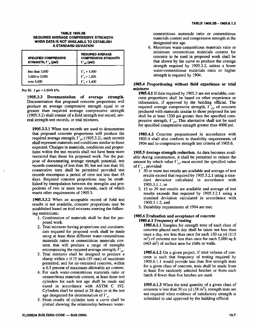
TABLE 1905.38 - 1905.6.1.3
TABLE 1905.38 REQUIRED AVERAGE COMPRESSIVE STRENGTH WHEN DATA IS NOT AVAILABLE TO ESTABLISH
A STANDARD DEVIATION
For SI: 1 psi = 6.8948 kPa.
SPECIFIED COMPRESSIVE STRENGTH, f ', (PI)
less than 3,000 3,000 to 5,000 over 5,000
1905.3.3 Documentation of average strength. Documentation that proposed concrete proportions will produce an average compressive strength equal to or greater than required average compressive strength (1905.3.2) shall consist of a field strength test record, sev- eral strength test records, or trial mixtures.
REQUIRED AVERAGE COMPRESSIVE STRENGTH
f 'c, (psi)
f ' ,+ 1,000 f ', + 1,200 f ', + 1,400
1905.3.3.1 When test records are used to demonstrate that proposed concrete proportions will produce the required average strength, f ',, (1905.3.2), such records shall represent materials and conditions similar to those expected. Changes in materials, conditions and propor- tions within the test records shall not have been more restricted than those for proposed work. For the pur- pose of documenting average strength potential, test records consisting of less than 30, but not less than 10, consecutive tests shall be permitted provided test records encompass a period of time not less than 45 days. Required concrete proportions may be estab- lished by interpolation between the strengths and pro- portions of two or more test records, each of which meets other requirements of 1905.3.
1905.3.3.2 When an acceptable record of field test results is not available, concrete proportions may be established based on trial mixtures meeting the follow- ing restrictions:
1. Combination of materials shall be that for pro- posed work.
2. Trial mixtures having proportions and consisten- cies required for proposed work shall be made using at least three different water-cementitious materials ratios or cementitious materials con- tents that will produce a range of strengths encompassing the required average strength, f I,,.
3. Trial mixtures shall be designed to produce a slump within +. 0.75 inch (19 mm) of maximum permitted, and for air-entrained concrete, within ? 0.5 percent of maximum allowable air content.
4. For each water-cementitious materials ratio or cementitious materials content, at least three test cylinders for each test age shall be made and cured in accordance with ASTM C 192. Cylinders shall be tested at 28 days or at the test age designated for determination of f ',.
5. From results of cylinder tests a curve shall be plotted showing the relationship between water-
cementitious materials ratio or cementitious materials content and compressive strength at the designated test age.
6. Maximum water-cementitious materials ratio or minimum cementitious materials content for concrete to be used in proposed work shall be that shown by the curve to produce the average strength required by 1905.3.2, unless a lower water-cementitious materials ratio or higher strength is required by 1904.
1905.4 Proportioning without field experience or trial mixtures
1905.4.1 If data required by 1905.3 are not available, con- crete proportions shall be based on other experience or information, if approved by the building official. The required average compressive strength, f ',, of concrete produced with materials similar to those proposed for use shall be at least 1200 psi greater than the specified com- pressive strength, f I,,. This alternative shall not be used for specified compressive strength greater than 4000 psi.
1905.4.2 Concrete proportioned in accordance with 1905.4 shall also conform to durability requirements of 1904 and to compressive strength test criteria of 1905.6.
1905.5 Average strength reduction. As data becomes avail- able during construction, it shall be permitted to reduce the amount by which value f ',, must exceed the specified value of f ', , provided:
1. 30 or more test results are available and average of test results exceed that required by 1905.3.2.1 using a stan- dard deviation calculated in accordance with 1905.3.1.1, or
2. 15 to 29 test results are available and average of test results exceeds that required by 1905.3.2.1 using a standard deviation calculated in accordance with 1905.3.1.2, and
3. Durability requirements of 1904 are met.
1905.6 Evaluation and acceptance of concrete 1905.6.1 Frequency of testing
1905.6.1.1 Samples for strength tests of each class of concrete placed each day shall be taken not less than once a day, nor less than once for each 150 cu yd (1 15 m3) of concrete nor less than once for each 5,000 sq ft (465 m2) of surface area for slabs or walls.
1905.6.1.2 On a given project, if total volume of con- crete is such that frequency of testing required by 1905.6.1.1 would provide less than five strength tests for a given class of concrete, tests shall be made from at least five randomly selected batches or from each batch if fewer than five batches are used.
1905.6.1.3 When the total quantity of a given class of concrete is less than 50 cu yd (38 m3), strength tests are not required when evidence of satisfactory strength is submitted to and approved by the building official.
FLORIDA BUILDING CODE - BUILDING

1905.6.1.4 A strength test shall be the average of the strengths of two cylinders made from the same sample of concrete and tested at 28 days or at a test age desig- nated for determination of f ',.
1905.6.2 Laboratory-cured specimens 1905.6.2.1 Samples for strength tests shall be taken in accordance with ASTM C 172.
1905.6.2.2 Cylinders for strength tests shall be molded and laboratory-cured in accordance with ASTM C 31 and tested in accordance with ASTM C 39.
1905.6.2.3 The strength level of an individual class of concrete shall be considered satisfactory if both of the following requirements are met:
1. Every arithmetic average of any three consecu- tive strength tests equals or exceeds f ',.
2. No individual strength test (average of two cylin- ders) falls below f ', by more than 500 psi (3450 Wa).
1905.6.2.4 If either of the requirements of 1905.6.2.3 is not met, steps shall be taken to increase the average of subsequent strength test results. Requirements of 1905.6.4 shall be observed if the requirement of 1905.6.2.3(2) is not met.
1905.6.3 Field-cured specimens 1905.6.3.1 The building official may require strength tests of cylinders cured under field conditions to check adequacy of curing and protection of concrete in the structure.
1905.6.3.2 Field-cured cylinders shall be cured under field conditions in accordance with ASTM C 3 1.
1905.6.3.3 Field-cured test cylinders shall be molded at the same time and from the same samples as laborato- ry-cured test cylinders.
1905.6.3.4 Procedures for protecting and curing con- crete shall be improved when the strength of field- cured cylinders at the test age designated for determi- nation of f ', is less than 85 percent of that of compan- ion laboratory-cured cylinders. The 85 percent may be waived if field-cured strength exceeds f ', by more than 500 psi (3450 kPa).
1905.6.4 Investigation of low-strength test results 1905.6.4.1 If any strength test (1905.6.1.4) of laborato- ry-cured cylinders falls below specified value off ', by more than 500 psi (3450 kPa) (1905.6.2.3(2)) or if tests of field-cured cylinders indicate deficiencies in protec- tion and curing (1905.6.3.4) steps shall be taken to assure that the load-carrying capacity of the structure is not jeopardized.
ing capacity may have been significantly reduced, tests of cores drilled from the area in question may be required in accordance with ASTM C 42. In such case, three cores shall be taken for each strength test more than 500 psi (3450 kPa) below specified value of f ',.
1905.6.4.3 If concrete in the structure will be dry under service conditions, cores shall be air dried (temperature 60 to 80°F (15.6 to 26.7OC), relative humidity less than 60%) for 7 days before test and shall be tested dry. If concrete in the structure will be more than superficial- ly wet under service conditions, cores shall be immersed in water for at least 40 hours and be tested wet.
1905.6.4.4 Concrete in an area represented by core tests shall be considered structurally adequate if the average of three cores is equal to at least 85% off ', and if no single core is less than 75% off ',. Additional test- ing of cores extracted from locations represented by erratic core strength results shall be permitted.
1905.6.4.5 If the criteria of 1905.6.4.4 are not met, and if structural adequacy remains in doubt, the engineer or the building official may order load tests as outlined in Chapter 20 of ACI 3 18 for the questionable portion of the structure, or take other appropriate action.
SECTION 1906 MIXING AND PLACING CONCRETE
1906.1 Preparation of equipment and place of deposit. Preparation before concrete placement shall include the fol- lowing:
1. All equipment for mixing and transporting concrete shall be clean.
2. All debris and ice shall be removed from spaces to be occupied by concrete.
3. Forms shall be properly coated. 4. Masonry filler units that will be in contact with con-
crete shall be well-drenched. 5. Reinforcement shall be thoroughly clean of ice or other
deleterious coating. 6. Water shall be removed from place of deposit before
concrete is placed unless a tremie is used or unless oth- erwise permitted by the building official.
7. All laitance and other unsound material shall be removed before additional concrete is placed against hardened concrete.
1906.2 Mixing 1906.2.1 All concrete shall be mixed until there is a uni- form distribution of materials and shall be discharged completely before the mixer is recharged.
1906.2.2 Ready-mixed concrete shall be mixed and deliv- ered in accordance with requirements of ASTM C 94 or ASTM C 685.
1905.6.4.2 If the likelihood of low-strength concrete is confirmed and computations indicate that load-carry-
FLORIDA BUILDING CODE - BUILDING

1906.2.3 Job-mixed concrete shall be mixed in accor- dance with ACI 318.
1906.3 Conveying 1906.3.1 Concrete shall be conveyed from mixer to place of final deposit by methods that will prevent separation or loss of materials.
1906.3.2 Conveying equipment shall be capable of pro- viding a supply of concrete at the site of placement with- out separation of ingredients and without interruptions sufficient to permit loss of plasticity between successive increments.
1906.4 Depositing 1906.4.1 Concrete shall be deposited as nearly as practi- cable in its final position to avoid segregation caused by rehandling or flowing.
1906.4.2 Concreting shall be carried on at such a rate that concrete is at all times plastic and flows readily into spaces between reinforcement.
1906.4.3 Concrete that has partially hardened or been con- taminated by foreign materials shall not be deposited in the structure.
1906.4.4 Retempered concrete or concrete that has been remixed after initial set shall not be used unless approved by the engineer.
1906.4.5 After concreting is started, it shall be carried on as a continuous operation until placing of a panel or sec- tion, as defined by its boundaries or predetermined joints, is completed, except as permitted or prohibited by 1907.4.
1906.4.6 Top surfaces of vertically formed lifts shall be generally level.
1906.4.7 When construction joints are required, joints shall be made in accordance with 1907.4.
1906.4.8 All concrete shall be thoroughly consolidated by suitable means during placement and shall be thoroughly worked around reinforcement and embedded fixtures and into comers of forms.
1906.5 Curing 1906.5.1 Concrete (other than high-early-strength) shall be maintained above 50°F (10°C) and in a moist condition for at least the first 7 days after placement, except when cured in accordance with 1906.5.3.
1906.5.2 High-early-strength concrete shall be maintained above 50°F (10°C) and in a moist condition for at least the first 3 days, except when cured in accordance with 1906.5.3.
1906.5.3 Accelerated curing shall conform to the follow- ing:
1. Curing by high pressure steam, steam at atmospher- ic pressure, heat and moisture, or other accepted processes, shall be permitted to accelerate strength gain and reduce time of curing.
2. Accelerated curing shall provide a compressive strength of the concrete at the load stage considered at least equal to required design strength at that load stage.
3. Curing process shall produce concrete with a dura- bility at least equivalent to the curing method of 1906.5.1 or 1906.5.2.
4. Supplementary strength tests in accordance with 1905.6.3 may be required to assure that curing is satisfactory.
1906.6 Cold weather requirements 1906.6.1 Adequate equipment shall be provided for heat- ing concrete materials and protecting concrete during freezing or near-freezing weather.
1906.6.2 All concrete materials and all reinforcement, forms, fillers and ground with which concrete is to come in contact shall be free from frost.
1906.6.3 Frozen materials or materials containing ice shall not be used.
1906.7 Hot weather requirements. During hot weather, proper attention shall be given to ingredients, production methods, handling, placing, protection and curing to prevent excessive concrete temperatures or water evaporation that may impair required strength or serviceability of the member or structure.
SECTION 1907 FORMWORK, EMBEDDED PIPES AND CONSTRUCTION JOINTS
1907.1 Design of formwork 1907.1.1 Forms shall result in a final structure that con- forms to shapes, lines and dimensions of the members as required by the design drawings and specifications.
1907.1.2 Forms shall be substantial and sufftciently tight to prevent leakage of mortar.
1907.1.3 Forms shall be properly braced or tied together to maintain position and shape.
1907.1.4 Fo,rms and their supports shall be designed so as not to damage the previously placed structure.
1907.1.5 Design of formwork shall include consideration of the following factors:
1. Rate and method of placing concrete, 2. Construction loads, including vertical, horizontal
and impact loads, and 3. Special form requirements for construction of
shells, folded plates, domes, architectural concrete or similar types of elements.
FLORIDA BUILDING CODE - BUILDING
1907.1.6 Forms for prestressed concrete members shall be designed and constructed to permit movement of the member without damage during application of prestress- ing force.
1907.2 Removal of forms, shores and reshoring 1907.2.1 Forms shall be removed in such manner as not to impair safety and serviceability of the structure. All con- crete to be exposed by form removal shall have sufficient strength not to be damaged by removal operation.
1907.2.2 Removal of shores and reshoring. The provi- sions of 1907.2.2.1 through 1907.2.2.3 shall apply to slabs and beams, except where they are cast on the ground.
1907.2.2.1 Before starting construction, the contractor shall develop a procedure and schedule for removal of shores and installation of reshores and for calculating the loads transferred to the structure during the process.
1907.2.2.1.1 The structural analysis and concrete strength data used in planning and implementing form removal and shoring shall be furnished by the contractor to the building official when required.
1907.2.2.1.2 No construction loads shall be support- ed on, nor any shoring removed from, any part of the structure under construction except when that portion of the structure in combination with the remaining forming and shoring system has suffi- cient strength to safely support its weight and loads placed thereon.
1907.2.2.1.3 Sufficient strength shall be demon- strated by structural analysis considering proposed loads, the strength of the forming and shoring sys- tem, and concrete strength data. Concrete strength data shall be based on tests of field-cured cylinders or, when approved by the building official, on other procedures to evaluate concrete strength.
1907.2.2.2 No construction loads exceeding the combi- nation of superimposed dead load plus specified live load shall be supported on any unshored portion of the structure under construction, unless analysis indicates adequate strength to support such additional loads.
1907.2.2.3 Form supports for prestressed concrete members shall not be removed until sufficient pre- stressing has been applied to enable prestressed mem- bers to carry their dead load and anticipated construc- tion loads.
1907.3 Conduits and pipes embedded in concrete 1907.3.1 Conduits, pipes and sleeves of any material not harmful to concrete and within the limitations of 1907.3 may be embedded in concrete with approval of the engi- neer, provided they are not considered to replace struc- turally the displaced concrete, except as provided in 1907.3.6.
1907.3.2 Conduits and pipes of aluminum shall not be embedded in structural concrete unless effectively coated or covered to prevent aluminum/concrete reaction or elec- trolytic action between aluminum and steel.
1907.3.3 Conduits, pipes and sleeves passing through a slab, wall or beam shall not impair significantly the strength of the construction.
1907.3.4 Conduits and pipes, with their fittings, embed- ded within a column shall not displace more than 4% of the area of cross section on which strength is calculated or which is required for fne protection.
1907.3.5 Except when plans for conduits and pipes are approved by the engineer, conduits and pipes embedded within a slab, wall or beam (other than those merely pass- ing through) shall satisfy the following:
1. They shall not be larger in outside dimension than one-third the overall thickness of slab, wall or beam in which they are embedded.
2. They shall not be spaced closer than three diameters or widths on center.
3. They shall not impair significantly the strength of the construction.
1907.3.6 Conduits, pipes and sleeves may be considered as replacing structurally in compression the displaced concrete provided:
1. They are not exposed to rusting or other deteriora- tion.
2. They are of uncoated or galvanized iron or steel not thinner than standard Schedule 40 steel pipe.
3. They have a nominal inside diameter not over 2 inches (51 mm) and are spaced not less than three diameters on centers.
1907.3.7 In addition to other requirements of 1907.3, pipes that will contain liquid, gas, or vapor may be embed- ded in structural concrete under the following conditions:
1. Pipes and fittings shall be designed to resist effects of the material, pressure and temperature to which they will be subjected.
2. No liquid, gas or vapor, except water not exceeding 90°F (32°C) nor 50 psi (345 kPa) pressure, shall be placed in the pipes until the concrete has attained its design strength.
3. In solid slabs, piping, unless it is for radiant heating or snow melting, shall be placed between top and bottom reinforcement.
4. Concrete cover for pipes, conduit and fittings shall be not less than 1112 inches (38 mm) for concrete exposed to earth or weather, nor 314 inch (19 mm) for concrete not exposed to weather or in contact with ground.
5. Reinforcement with an area of not less than 0.002 times the area of concrete section shall be provided normal to piping.
6. Piping and conduit shall be so fabricated and installed that cutting, bending or displacement of reinforcement from its proper location will not be required.
FLORIDA BUILDING CODE - BUILDING

1907.4 Construction joints 1907.4.1 Surface of concrete construction joints shall be cleaned and laitance removed.
1907.4.2 Immediately before new concrete is placed, all construction joints shall be wetted and standing water removed.
1907.4.3 Construction joints shall be so made and located as not to impair the strength of the structure. Provision shall be made for transfer of shear and other forces through construction joints.
1907.4.4 Construction joints in floors shall be located within the middle third of spans of slabs, beams and gird- ers. Joints in girders shall be offset a minimum distance of two times the width of intersecting beams.
1907.4.5 Beams, girders or slabs supported by columns or walls shall not be cast or erected until concrete in the ver- tical support members is no longer plastic.
1907.4.6 Beams, girders, haunches, drop panels and capi- tals shall be placed monolithically as part of a slab system, unless otherwise shown in design drawings or specifica- tions.
SECTION 1908 DETAILS OF REINFORCEMENT
1908.1 General. Details of reinforcement shall comply with the requirements of this section and ACI 318.
1908.2 Bending reinforcement 1908.2.1 All reinforcement shall be bent cold, unless oth- erwise approved by the engineer.
1908.2.2 Reinforcement partially embedded in concrete shall not be field bent except as shown on the design drawings or approved by the engineer.
1908.3 Surface conditions of reinforcement 1908.3.1 At the time concrete is placed, reinforcement shall be free from mud, oil or other nonmetallic coatings that decrease the bond. Epoxy coating of bars in accor- dance with the standards listed in ACI 318 is permitted.
1908.3.2 Reinforcement, except prestressing tendons, with rust, mill scale or a combination of both shall be con- sidered satisfactory, provided the minimum dimensions (including height of deformations) and weight of a hand- wire-brushed test specimen are not less than applicable specification requirements in the ASTM standards refer- enced in ACI 3 18.
1908.3.3 Prestressing tendons shall be clean and free of oil, dirt, scale, pitting and excessive rust. A light oxide is permissible.
1908.4 Placing reinforcement 1908.4.1 Reinforcement, prestressing tendons and ducts shall be accurately placed and adequately supported before concrete is placed, and shall be secured against dis- placement within tolerances permitted in 1908.4.2.
Exception: When approved by the engineer, embedded items (such as dowels or inserts) of precast concrete members that either protrude from concrete or remain exposed for inspection may be embedded while the concrete is in a plastic state provided:
1. Embedded items shall not be required to be hooked or tied to reinforcement within plastic concrete.
2. Embedded items shall be maintained in correct position while concrete remains plastic.
3. Embedded items shall be properly anchored to develop required factored loads.
1908.4.2 Unless otherwise specified by the engineer, rein- forcement, prestressing tendons and prestressing ducts shall be placed within the following tolerances:
1. Tolerance for depth, d, and minimum concrete cover in flexural members, walls and compression mem- bers shall be as follows:
MEMBER TOLERANCEON MINIMUM CONCRETE COVER
d S 8 in. * 318 in. -31s in. d > 8 in. * lh in. -112 in.
For SI: 1 in = 25.4 mm.
Except that tolerance for the clear distance to formed soffits shall be minus 114 inch (6 mm) and tolerance for cover shall not exceed minus one-third the minimum concrete cover required in the design drawings or specifications. Tolerance for longitudinal location of bends and ends of reinforcement shall be A 2 inches (* 5 1 mm) except at discontinuous ends of members, where tol- erance shall be i 112 inch (A 12.7 mm).
1908.4.3 Welded wire fabric (with wire size not greater than W5 or D5) used in slabs not exceeding 10 ft (3048 mm) in span may be curved from a point near the top of the slab over the support to a point near the bottom of the slab at midspan, provided such reinforcement is either continuous over, or securely anchored at support.
1908.4.4 Crossing bars shall not be welded for assembly of reinforcement unless approved by the engineer.
1908.5 Spacing limits for reinforcement. The clear distance between reinforcing bars, bundled bars, prestressing tendons and ducts shall be in accordance with the limitations of ACI 318.
FLORIDA BUILDING CODE - BUILDING

1908.6 - 1911
1908.6 Concrete protection for reinforcement1908.6.1 Concrete cover shall be provided for reinforce-ment in cast-in-place concrete (non-prestressed) in accor-dance with Table 1908.6.
1908.6.2 The minimum cover for reinforcement in precastconcrete manufactured under plant control conditions, andfor prestressed concrete, shall be in accordance with ACI318.
1908.6.3 In corrosive environments or other severe expo-sure conditions, the amount of concrete protection shall besuitably increased, and denseness and nonporosity of pro-tecting concrete shall be considered, or other protectionshall be provided.
1908.6.4 Exposed reinforcement, inserts and platesintended for bonding with future extensions shall be pro-tected from corrosion.
1908.6.5 When this code requires a thickness of cover forfire protection greater than the minimum concrete coverspecified in 1908.6 or ACI 318, such greater thicknessesshall be used.
TABLE 1908.6CAST-IN-PLACE CONCRETE REINFORCEMENT PROTECTION
EXPOSURE
Concrete cast against and permanentlyexposed to earth
Concrete exposed to earth or weather:#6 through #18 bars#5 bar, W31 or D31 wire, and smaller
Concrete not exposed to weather or incontact with ground:
Slabs, walls, joists:#14 and #18 bars#11 bar and smaller
Beams, columns:Primary reinforcement, ties,stirrups, spirals
Shells, folded plate members:#6 bar and larger#5 bar, W31 or D31 wire, andsmaller
MINIMUMCONCRETE COVER(In.)
3 (76 mm)
2 (51 mm)l1/2 (38 mm)
11/2 (38 mm)3/4 (19 mm)
l1/2 (38 mm)
3/4 (19 mm)
1/2 (12.7 mm)
SECTION 1909SLAB ON GROUND
1909.1 Minimum thickness. The minimum thickness ofconcrete floor slabs supported directly on the ground shall benot less than 31/2 inches (89 mm) unless designed by anarchitect or engineer.
1909.2 Vapor retarder. A vapor retarder consisting of 6 mil(0.152 mm) minimum polyethylene with joints lapped 6 inches(152 mm) and sealed, or other approved materials having a max-imum perm rating of 0.5 [2.873 x 10⁻⁵ mg/(Pa • s • m2)] shall beinstalled underneath the slab.
Exceptions: The vapor retarder may be omitted:1. from detached structures accessory to one- and two-
family dwellings such as garages, utility buildingsor other unheated facilities.
2. from buildings of other uses when migration ofmoisture through the slab from below will not bedetrimental to the intended use of the building.
3. from driveways, walks, patios and other flat worknot likely to be enclosed and heated at a later date,
4. where approved by the building official, based onlocal site conditions.
1909.3 Joints. Concrete slabs on ground shall be providedwith joints in accordance with ACI 224.3R or other approvedmethods. Joints shall be designed by an architect or engineer.
Exception: Joints are not required in unreinforced plainconcrete slabs on ground or in slabs for one- and two-fam-ily dwellings complying with one of the following:
1. Concrete slabs on ground containing synthetic fiberreinforcement. Fiber lengths shall be 1/2 inch to 2 inch-es (13 to 51 mm) in length. Dosage amounts shall befrom 0.75 to 1.5 pounds per cubic yard (0.45 to 0.89kg/m3) in accordance with the manufacturer's recom-mendations. Synthetic fibers shall comply with ASTMC 1116. The manufacturer or supplier shall providecertification of compliance with ASTM C 1116 whenrequested by the building official; or,
2. Concrete slabs on ground containing 6x6 W1.4 xW1.4 welded wire reinforcement fabric located inthe middle to the upper 1/3 of the slab. Welded wirereinforcement fabric shall be supported withapproved materials or supports at spacings not toexceed 3 ft (914 mm) or in accordance with themanufacturer's specifications. Welded plain wirereinforcement fabric for concrete shall conform toASTM A 185, Standard Specification for SteelWelded Wire Reinforcement Fabric, Plain, forConcrete Reinforcement.
SECTION 1910GFRC EXTERIOR WALL PANELS
The minimum thickness of glass fiber reinforced concrete(GFRC) exterior wall panels shall be 3/8 inch (9.5 mm).
Exceptions:1. Sandwich wall panels2. Glass fiber reinforced concrete wall forms which are
left in place.
SECTION 1911PARAPET WALLS
Provisions for parapet walls are contained in 1511.6.
19.12 FLORIDA BUILDING CODE — BUILDING
1912-1914.1.3
SECTION 1912(Reserved)
SECTION 1913REINFORCED GYPSUM CONCRETE
1913.1 Standard specifications. Reinforced poured gypsumconcrete shall conform to the requirements of ASTM C 317.The design and application of reinforced gypsum concreteshall be in accordance with the requirements of ASTM C956.
1913.2 Inspection. A competent inspector, satisfactory to thebuilding official, shall be present on the work at all timeswhen cast-in-place gypsum concrete is being mixed ordeposited.
SECTION 1914HEADED BOLTS AND HEADED STUD
ANCHORS IN CONCRETE
1914.1 Headed bolts and headed stud anchors shall be solid-ly cast in concrete. The factored loads on embedded headedbolts and headed stud anchors shall not exceed the designstrengths determined by 1914.1.2.
1914.1.1 Load factor multipliers. In addition to the loadfactors in 1609, a multiplier of 2 shall be used if specialinspection is not provided or of 1.3 if it is provided. Whereanchors are embedded in the tension zone of a member,the load factors in 1609 shall have a multiplier of 3 if spe-cial inspection is not provided or of 2 if it is provided.
1914.1.2 Strength of anchors. The strength of headedbolts and headed stud anchors solidly cast in concreteshall be taken as the average of 10 tests for each concretestrength and anchor size or calculated in accordance with1914.1.4 through 1914.1.5. The bearing area of headedanchors shall be at least one and one-half times the shankarea for anchors of not over 60,000 psi (414 MPa) yieldstrength.
1914.13 Strength in tension. The design strength of anchorsin tension shall be the minimum of Ps or Pc where:
and for an anchor group where the distance betweenanchors is less than twice their embedment length
or for a single anchor or anchor group where the distancebetween anchors is equal to or greater than twice theirembedment length
where:Ab = Area (sq in.) of bolt or stud. Must be used
with the corresponding steel properties todetermine the weakest part of the assemblyin tension. In shear, the insert leg need notbe checked.
AS = The sloping area (sq in.) of an assumed fail-ure surface. For a single anchor or anchorgroup where the distance between anchorsis equal to or greater than twice theirembedment length, the surface is assumedto be that of a truncated cone radiating at a45 degree (0.785 rad) slope from the bearingedge of the anchor to the surface.
For an anchor group where the distance betweenanchors is less than twice their embedmentlength, the failure surface is assumed to be that ofa truncated pyramid radiating at a 45 degree(0.785 rad) slope from the bearing edge of theanchor group to the surface.
In addition, for thin sections with anchor groups,the failure surface shall be assumed to follow theextension of this slope through to the far siderather than truncate as in At (i.e., At = 0) and thefailure mode resulting in the lower value of Pc
shall control.
At = The area (sq in.) of the flat bottom of thetruncated pyramid of an assumed concretefailure surface. Where anchors in a groupare closer than twice their embedmentlength, the failure surface pyramid isassumed to truncate at the anchor bearingedge rather than form separate cones.
f 'c = Specified compressive strength of concrete(psi), which shall not be taken greater than6,000 psi (41 MPa) for design.
f 's = Ultimate tensile strength (psi) of the bolt,stud or insert leg wires, which shall not betaken greater than 60,000 psi (414 MPa).For A307 bolts or A108 studs, f 's may beassumed to be 60,000 psi (414 MPa).
Pu = Tensile strength required because of fac-tored loads (lb).
Vu = Shear strength required because of factoredloads (lb).
= 1 for normal weight concrete, 0.75 for "alllightweight" concrete, and 0.85 for "sand-lightweight" concrete.
= Strength reduction factor shall be taken as0.65, except is permitted to be taken as 0.85where the anchor is attached to or hookedaround reinforcing steel or otherwise termi-nated so as to effectively transfer forces toreinforcing steel that is designed to distributeforces and avert sudden local failure.
FLORIDA BUILDING CODE — BUILDING 19.13
Ps = 0.9Abf 's

1914.1.4-1915.8.3
Where edge distance is less than embedment length,reduce Pc proportionately. For multiple edge dis-tances less than the embedment length, use multiplereductions.
1914.1.4 Strength in shear. The design strength of anchorsin shear shall be the minimum of Vs or Vc where:
Vs = 0.75Abf 's
and where loaded toward an edge equal to or greater than10 diameters away
or where loaded toward an edge less than 10 diameters away
where de = distance from the anchor axis to the free edge.
For groups of anchors, the concrete design shear strengthshall be taken as the smallest of:
1. The design strength of the weakest stud times thenumber of studs,
2. The design strength of the row of studs nearest thefree edge in the direction of shear times the numberof rows, or
3. The design strength of the row farthest from the freeedge in the direction of shear.
For shear loading toward an edge less than 10 diametersaway, or tension or shear not toward an edge less than 4diameters away, reinforcing sufficient to carry the loadshall be provided to prevent failure of the concrete in ten-sion. In no case shall the edge distance be less than one-third the above.
1914.1.5 Combined tension and shear. Where tension andshear act simultaneously, both of the following shall be met:
1914.1.6 Special provisions for anchor bolts in tops ofcolumns. Anchor bolts at the tops of columns shall beenclosed with not less than two #4 ties located within 4inches (102 mm) from the top of the column. Anchor boltsin the tops of columns shall be embedded not less than 9-bolt diameters.
SECTION 1915SHOTCRETE
1915.1 General. Except as specified in this section, shotcreteshall conform to the requirements for plain concrete or rein-forced concrete.
1915.2 Proportioning. Shotcrete proportions shall be select-ed that allow suitable placement procedures using the deliv-ery equipment selected, and that results in in-place hardenedshotcrete conforming to the strength requirements of thiscode.
1915.3 Aggregate. Coarse aggregate, if used, shall notexceed 3/4 inch (19 mm) in size.
1915.4 Reinforcement1915.4.1 General. Reinforcement shall comply with1915.4.1 through 1915.4.3.
1915.4.2 Size. The maximum size of reinforcement shallbe No. 5 bars. The building official shall approve the useof larger bars where it is demonstrated that adequateencasement of the larger bars will be achieved.
1915.4.3 Spacing. The minimum clearance between par-allel reinforcing bars shall be 21/2 inches (64 mm). Weldedwire fabric shall have a minimum wire spacing of 2 inch-es (51 mm) by 2 inches (51 mm).
1915.4.4 Splices. Lap splices of reinforcing bars shall beby the noncontact lap-splice method with at least 2 inches(51 mm) of clearance between bars. The building officialshall permit the use of contact splices where necessary forthe support of the reinforcing and provided that it isdemonstrated adequate encasement of the bars at thesplice will be achieved.
1915.5 Rebound. Any rebound or accumulated loose aggre-gate shall be removed from the surfaces to be covered priorto placing the initial or any succeeding layers of shotcrete.Rebound shall not be reused as aggregate.
1915.6 Joints. Except where permitted herein, unfinishedwork shall not be allowed to stand for more than 30 minutesunless all edges are sloped to a thin edge. For structural ele-ments which will be under compression and for constructionjoints shown on the approved construction documents,square joints are permitted. Before placing additional mater-ial adjacent to previously applied work, sloping and squareedges shall be cleaned and wetted.
1915.7 Damage. Shotcrete that exhibits sags, sloughs, segre-gation, honeycombing, sand pockets or other obvious defectsshall be removed and replaced.
1915.8 Curing1915.8.1 General. During the cure periods specified here-in, shotcrete shall be maintained above 40°F (4°C) and ina moist condition.
1915.8.2 Initial curing. Shotcrete shall be kept continu-ously moist for 24 hours after shotcreting is completed orshall be sealed with an approved curing compound.
1915.8.3 Final curing. Final curing shall continue for 7days after shotcreting, or for 3 days if high-early-strengthcement is used, or until the specified strength is obtained.
19.14 FLORIDA BUILDING CODE — BUILDING
1915.8.4-TABLE 1916.3
Final curing shall consist of the initial curing process orthe shotcrete shall be covered with an approved moisture-retaining cover.
1915.8.4 Natural curing. Natural curing shall not be usedin lieu of that specified in 1915.8 unless the relativehumidity remains at or above 85 percent, and is authorizedby the registered design professional and approved by thebuilding official.
1915.9 Strength test A strength test of shotcrete shall bemade in accordance with the quality assurance provisions ofACI 506.2.
SECTION 1916INSULATED CONCRETE FORM WALL
CONSTRUCTION
1916.1 General. Insulated concrete form (ICF) walls aboveground shall be designed and constructed in accordance withthis section or in accordance with the provisions of ACI 318,or other approved structural standards.
1916.2 Applicability limits. Buildings constructed withinsulated concrete form walls in accordance with this sectionare subject to the following limitations:
1. Building plan dimensions do not exceed 60 ft (18.3 m).2. Floors spans do not exceed 32 ft (9.7 m) and roof spans
do not exceed 40 ft (12 m) clear.3. Buildings are two stories or less in height above-grade
with no story greater than 10 ft (3.0 m) high.4. Buildings are located in areas where the basic wind
speeds in Figure 1606 are 100 mph or less.5. Building floor live loads do not exceed 40 psf (1.92
kN/m2).
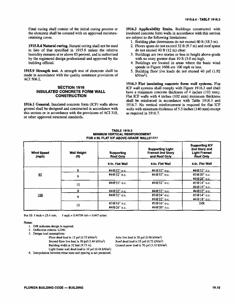
1916.3 Flat insulating concrete form wall systems. FlatICF wall systems shall comply with Figure 1916.3 and shallhave a minimum concrete thickness of 4 inches (102 mm).Flat ICF walls with 4 inches (102 mm) minimum thicknessshall be reinforced in accordance with Table 1916.3 and1916.7. No vertical reinforcement is required for flat ICFwalls with minimum thickness of 5.5 inches (140 mm) exceptas required in 1916.7.
TABLE 1916.3MINIMUM VERTICAL REINFORCEMENT
FOR 4 IN. FLAT ICF ABOVE-GRADE WALLS1,2,3,4
Wind Speed(mph)
100
Wall Height(ft)
8
9
10
8
9
10
SupportingRoof Only
4-in. Flat Wall
#4@32" o.c.#4@32" o.c.
#4@32" o.c.
#4@32" o.c.#4@32" o.c.
#3@16" o.c.#4@26" o.c.
Supporting LightFramed 2nd Story
and Roof Only
4-in. Flat Wall
#4@32" o.c.#4@32" o.c.
#4@32" o.c.
#4@32" o.c.#3@24" o.c.#4@32" o.c.#3 @ 16" o.c.#4@ 20" o.c.
Supporting ICF2nd Story andLight Framed
Roof Only
4-in. Flat Wall
#4@ 32" o.c.#3@20" o.c.#4@24" o.c.#3 @ 14" o.c.#4@ 16"o.c.#4@32" o.c.#3 @ 14" o.c.#4@ 18"o.c.
D/R
For SI: 1 inch = 25.4 mm, 1 mph = 0.44704 m/s = 0.447 m/sec
Notes:1. D/R indicates design is required.2. Deflection criteria: L/240.3. Design load assumptions:
Floor dead load is 15 psf (0.72 kN/m2)Second floor live load is 30 psf (1.44 kN/m2)Building width is 32 feet (9.75 m)Light frame wall dead load is 10 psf (0.48 kN/m2)
4. Interpolation between rebar sizes and spacing is not permitted.
Attic live load is 20 psf (0.96 kN/m2)Roof dead load is 15 psf (0.72 kN/m2)Ground snow load is 70 psf (3.35 kN/m2)
FLORIDA BUILDING CODE — BUILDING 19.15

1916.4-1916.7.3.4
1916.4 Waffle-grid insulating concrete form wall systems.Waffle-grid ICF wall systems shall comply with Figure1916.4 and shall be reinforced in accordance with 1916.7.The minimum core dimensions shall comply with Table1916.4.
1916.5 Screen-grid insulating concrete form wall systems.Screen-grid ICF wall systems shall comply with Figure1916.5 and shall be reinforced in accordance with 1916.7.The minimum core dimensions shall comply with Table1916.4.
1916.6 Material Requirements. Materials used for insulat-ed concrete form walls shall comply with this section.
1916.6.1 Concrete material. Concrete shall meet therequirements of this chapter and shall have a maximumslump not greater than 6 inches (152 mm) as determinedin accordance with ASTM C 143. The maximum aggre-gate size shall not be larger than 3/4inch (19 mm).
Exception: Concrete mixes conforming to the ICFmanufacturer's recommendations.
1916.6.2 Reinforcing steel. Reinforcing steel shall meetthe requirements of this chapter and shall have a minimumyield strength (fy) of 40,000 psi (Grade 40) (276 Mpa).Vertical and horizontal wall reinforcements shall not beplaced within the outside third of the wall. Steel rein-forcement shall have concrete cover in accordance with1908.6.
Exception: Where insulated concrete forms are usedand the form remains in place as cover for the concrete,the minimum concrete cover for the reinforcing steelmay be reduced to 3/4 inch.
1916.6.3 Insulation Materials. Insulating concrete formmaterial shall meet the surface-burning characteristics of2603.4. A thermal barrier shall be provided in accordancewith 2603.5. Adhesives are permitted to be used in con-junction with mechanical fasteners. Adhesives used forinterior and exterior finishes shall be compatible with theinsulating form materials.
1916.7 Wall construction. Insulating concrete form wallsshall be constructed in accordance with the provisions of thissection and Figure 1916.7.
1916.7.1 Horizontal reinforcement. ICF walls shall havehorizontal reinforcement in accordance with this section.ICF walls with a minimum thickness of 4 inches (102mm) shall have a minimum of one continuous #4 horizon-tal reinforcing bar placed at 32 inches (812 mm) on centerwith one bar within 12 inches (305 mm) of the top of thewall story. Concrete walls 5.5 inches (140 mm) thick orgreater shall have a minimum of one continuous #4 hori-zontal reinforcing bar placed at 48 inches (1.2 m) on cen-ter with one bar located within 12 inches (305 mm) of thetop of the wall story.
Horizontal reinforcement shall be continuous aroundbuilding corners using corner bars or by bending the bar.In either case, the minimum lap splice shall be 24 inches(610 mm).
1916.7.2 Wall Openings. Wall openings shall have a min-imum of 8 inches (203 mm) of depth of concrete over thelength of the opening for flat and waffle-grid walls and 12inches (308 mm) for screen-grid walls. Reinforcementaround openings shall be provided in accordance withTable 1916.7.2 and Figure 1916.7.2. All reinforcementplaced horizontally above or below an opening shallextend a minimum of 24 inches (610 mm) beyond the lim-its of the opening. Wall opening reinforcement shall beprovided in addition to the reinforcement required in1916.3, 1916.4, 1916.5 and 1916.7.1. The perimeter of allwall openings shall be framed with a minimum 2x4preservative-treated plate, anchored to the wall with 1/2-inch (12.7 mm) diameter anchor bolts spaced a maximumof 24 inches (610 mm) on center. The bolts shall beembedded into the concrete a minimum of 4 inches (102mm) and shall have a minimum of 1 1/2 inches (38 mm) ofconcrete cover to the face of the wall.
1916.7.3 Lintels.1916.7.3.1 General requirements. Lintels shall beprovided over all openings greater than or equal to 4feet (1.2 m) in width. Lintels for flat ICF walls andscreen-grid walls shall be constructed in accordancewith Figures 1916.7.2 and 1916.7.3a. Lintels for waf-fle-grid ICF walls shall be constructed in accordancewith Figures 1916.7.2 and 1916.7.3b or 1916.7.3c.Lintel depths may be increased by the height of the ICFwall located directly above the lintels, provided that thelintel depth spans the entire length of the opening.
1916.7.3.2 Stirrups. A minimum of #3 stirrups shall beinstalled for all lintels at a maximum spacing of d/2where d equals the depth of the lintel (D) minus thebottom cover of concrete as shown in Figure 1916.7.3a,1916.7.3b or 1916.7.3c. Where the spacing of stirrupsin waffle-grid walls places the strirrup between verticalcores, the stirrup shall be relocated to the closest verti-cal core. In no case shall the total number of requiredstirrups be reduced.
1916.7.3.3 Horizontal reinforcement One #4 hori-zontal bar shall be provided in the top of the lintel.Horizontal reinforcement placed within 12 inches (305mm) of the top of the wall in accordance with 1916.7.1shall be permitted to serve as the top or bottom rein-forcement in the lintel, provided the reinforcementmeets the location requirements in Figure 1916.7.2,1916.7.3a, 1916.7.3b or 1916.7.3c and the size require-ments in Table 1916.7.3a, 1916.7.3b, 1916.7.3c,1916.7.3d, 1916.7.3e or 1916.7.3f.
1916.7.3.4 Loadbearing walls. Lintels for flat andscreen-grid ICF walls supporting roof or floor loadsshall comply with Table 1916.7.3a or 1916.7.3b.
19.16 FLORIDA BUILDING CODE — BUILDING

1916.7.3.5-1917.2.1
Lintels for waffle-grid ICF walls supporting roof orfloor loads shall comply with Table 1916.7.3c or1916.7.3d.
Exception: Where spans larger than those permittedin Table 1916.7.3a, 1916.7.3b, 1916.7.3c or1916.7.3d are required, the lintels shall comply withTable 1916.7.3e.
1916.7.3.5 Gabled endwalls. Lintels for gabled end-walls for flat, waffle-grid and screen-grid ICF wallsshall comply with Table 1916.7.3f.
1916.7.4 Minimum length of wall without openings.Exterior ICF walls shall have a minimum of solid walllength to total wall length in accordance with Table1916.7.4 but not less than 15 percent for ICF walls sup-porting a light framed roof or 20 percent for ICF wallssupporting an ICF or light framed second story and lightframed roof. The minimum percentage of solid walllength in Table 1916.7.4 shall include only those solidwall segments which are a minimum of 24 inches (610mm) in length. The maximum distance between wall seg-ments shall not exceed 18 feet (5.5 m) on center. A mini-mum length of 24 inches (610 mm) of solid wall segment,extending the full height of each wall story, shall occur atall corners of exterior walls.
1916.7.5 Protection against termites1916.7.5.1 Clearance between earth and insulated concreteforms (ICF) shall be not less than 6 inches (152 mm).
1916.7.5.2 Foam plastic insulation shall be permittedbelow grade on walls in accordance with one of the fol-lowing conditions:
1. When in addition to the requirements of2304.1.2, an approved method of protecting thefoam plastic and structure from subterranean ter-mite damage is provided.
2. Within Types I, II, and IV construction.3. On the interior side of basement walls.
1916.8 ICF wall to floor/roof connections.1916.8.1 Framed floors/roofs bearing on the top of ICFwalls in accordance with Figures 1916.8.1a or 1916.8.1bshall be attached to wood sill plates anchored to the wallin accordance with 2307.1. Anchor bolts shall be locatedin the cores of waffle-grid and screen-grid ICF walls.
1916.8.2 Wood ledger boards supporting bearing ends ofjoists or trusses shall be anchored to flat ICF walls withminimum thickness of 5.5 inches (140 mm) and to waffle-or screen-grid ICF walls with minimum nominal thicknessof 6 inches (152 mm) in accordance with Figures1916.8.2a, 1916.8.2b, 1916.8.2c or 1916.8.2d. The ledgershall be a minimum 2x8 No. 2 Southern Pine or No. 2
Douglas Fir. Ledgers shall be attached to non-loadbearingwalls with V2-inch (12.7 mm) diameter anchor boltsspaced a maximum of 6 feet (1829 mm) on center. Anchorbolts shall be embedded a minimum of 4 inches (102mm).
SECTION 1917LIGHTWEIGHT INSULATING CONCRETE FILL
1917.1 Lightweight Insulating concrete fill. Material pro-duced with or without aggregate additions to portlandcement, water and air to form a hardened material possessinginsulating qualities, which, when oven dried shall have a unitweight no greater than 50 pcf (801 kg/m3).
1917.1.1 Aggregate lightweight insulating concrete.Insulating concrete fill formulated predominantly withperlite, vermiculite or expanded polystyrene beads. It shallhave a minimum compressive strength of 125 psi (861.8kPa) when tested in compliance with ASTM C 495 and C796.
1917.1.2 Cellular lightweight insulating concrete.Insulating concrete fill formulated by mixing a hydratedcementitious matrix around noninterconnecting air cellscreated by the addition of foam concentrates formed fromhydrolyzed proteins or synthetic surfactants. The curedcellular lightweight insulating concrete shall have mini-mum compressive strength of 160 psi (1103 kPa) whentested in compliance with ASTM C495 and C796.
1917.1.3 Cellular/aggregate (Hybrid) lightweight insu-lating concrete. Insulated concrete fill formulated bycombining foam concentrates with low density aggregatesto import properties of both aggregate and cellular light-weight insulating fill. It shall have a minimum compres-sive strength of 200 psi (1379 kPa) when tested in com-pliance with ASTM C495 and C796.
1917.1.4 Walkability. A term defining the ability of light-weight insulating fill to withstand anticipated constructiontraffic during the roof membrane application without sig-nificant indentations in the lightweight insulating concretefill surface.
1917.2 Inspection.1917.2.1 Application of all lightweight insulating con-crete fill roof decks shall be by applicators approved bythe lightweight insulating concrete deck manufacturer.Product Control Approval shall be required for all light-weight insulation concrete fill systems.
FLORIDA BUILDING CODE — BUILDING 19.17

TABLE 1916.4 - TABLE 1916.7.2
TABLE 1916.4DIMENSIONAL REQUIREMENTS FOR CORES AND WEBS IN
WAFFLE-GRID AND SCREEN-GRID ICF WALLS1-2
WallType
Waffle-GridWaffle-GridScreen-Grid
NominalSize(in.)
686
Minimum Widthof Core, W
(in.)
6.257
5.5
MinimumThickness of
Vertical Core, T(in.)
57
5.5
MaximumSpacing of
Vertical Cores(in.)
121212
MaximumSpacing of
Horizontal Cores(in.)
161612
Minimum WebThickness
(In.)
22
N/A
For SI: 1 inch = 25.4 mm
Notes:1. For width "W", thickness "T"; spacing, and web thickness, refer to Figures 1916.4 and 1916.5.2. N/A indicates not applicable.
TABLE 1916.7.2WALL OPENING MINIMUM REINFORCEMENT REQUIREMENTS
OpeningWidth
(ft)
Flat, Waffleand Screen-Grid:
L<2
Screen-Grid2< L<4
Flat andWaffle-Grid2< L<4
Flat, Waffleand Screen-Grid
L> 4
Horizontal Reinforcing
None Required
One No. 4 bar a minimum of 1.5 inches (38 mm)and a maximum of 2.5 inches (64 mm)from the top of the opening. One No. 4 barwithin 12 inches (305 mm) of the bottom ofthe opening. Each No. 4 bar shall extend aminimum of 24 inches (610 mm) beyond thelimits of the opening.
One #4 bar within 12 inches (305 mm) of bottom ofopening and at top of opening with minimumof 24 inches (610 mm) embedment beyond each sideof opening for flat and waffle-grid walls.
Provide lintels in accordance with Section1916.7.3. Top and bottom reinforcement shallextend a minimum of 24 inches (610 mm) beyondthe opening.
Vertical Reinforcing
None Required
None Required
None Required
One #4 bar within 12 inches (305 mm)of each side of opening. Rebar shallextend the full height of the wallstory.
For SI: 1 inch = 25.4 mm, 1 ft = 0.3 m
19.18 FLORIDA BUILDING CODE — BUILDING

TABLE 191 6.7.3a
TABLE 191 6.7.3a MAXIMUM ALLOWABLE CLEAR SPANS FOR
FLAT ICF WALL LINTELSl*ZJ*' #4 Bottom Bar Size
For SI: 1 inch = 25.4 mm, 1 psf = 0.0479 kNIm2 1 ft = 0.3 rn
Minimum Lintel Width, W
(in.)
4
5.5
7.5
9.5
Notes: 1. Deflection criteria: U240. 2. Design load assumptions:
Floor dead load is 10 psf (0.48 kNIm2) Attic live load is 20 psf (0.96 kN/m2) Floor live load is 30 psf (1.44 kNlm2) Roof dead Load is 15 psf (0.72 kNlm2) Building width is 32 feet (9.75 m) ICF wall dead load is 69 psf (3.31 kNIm2) Light framed wall dead load is 10 psf (0.48 kN/m2)
3. #3 stirrups are required at dl2 spacing. 4. Interpolation is permitted between lintel depths.
FLORIDA BUILDING CODE - BUILDING
Lintel Depth, D
(in.)
8 12 16 20 24 8 12 16 20 24 8 12 16 20 24 8 12 16
Maximum Clear Span, (ft-in.)
Supporting Light- Framed Roof
4-9 6-8 7-1 1 8-1 1 9-10 5-2 6-8 7-10 8-10 9-8 5-2 6-7 7-9 8-8 9-6 5-2 6-7 7-8
Supporting Light- Framed 2nd Story and
Root
3-10 5-0 6-0 6-9 7-6 3-10 5 -0 6-0 6-9 7-5 3-1 1 5-0 5-1 1 6-8 7-4 3-1 1 5-0 5-1 1
Supporting ICF Second Story and Light-Framed Roof
3-5 4-6 5-4 6-1 6-9 3-5 4-6 5-4 6-1 6-8 3-6 4-6 5-4 6-0 6-7 3-6 4-6 5-4
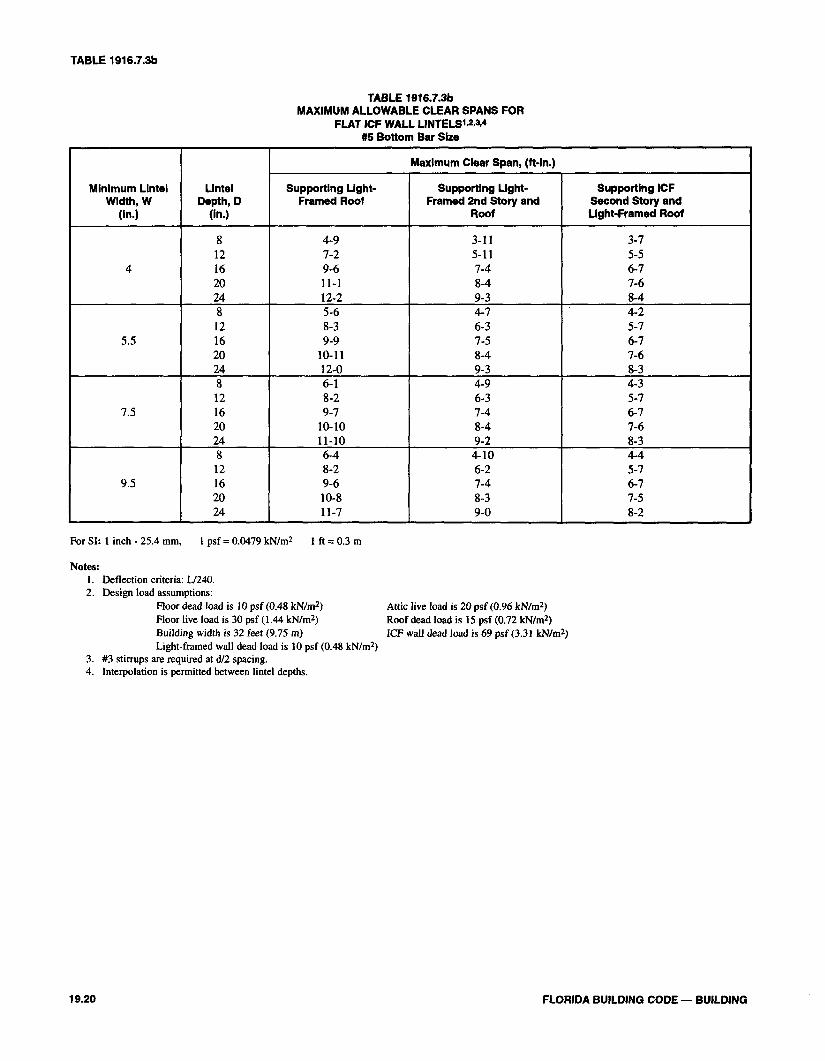
TABLE 1916.7.3b
TABLE 1916.7.3bMAXIMUM ALLOWABLE CLEAR SPANS FOR
FLAT ICF WALL LINTELSW-4#5 Bottom Bar Size
Minimum LintelWidth, W
(In.)
4
5.5
7.5
9.5
LintelDepth, D
(in.)
812162024812162024812162024812162024
Maximum Clear Span, (ft-in.)
Supporting Light-Framed Roof
4-97-29-611-112-25-68-39-9
10-1112-06-18-29-7
10-1011-106-48-29-610-811-7
Supporting Light-Framed 2nd Story and
Roof
3-115-117-48-49-34-76-37-58-49-34-96-37-48-49-24-106-27-48-39-0
Supporting ICFSecond Story andLight-Framed Roof
3-75-56-77-68-44-25-76-77-68-34-35-76-77-68-34-45-76-77-58-2
For SI: 1 inch - 25.4 mm, 1 psf = 0.0479 kN/m2 1 ft = 0.3 m
Notes:1. Deflection criteria: L/240.2. Design load assumptions:
Floor dead load is 10 psf (0.48 kN/m2)Floor live load is 30 psf (1.44 kN/m2)Building width is 32 feet (9.75 m)Light-framed wall dead load is 10 psf (0.48 kN/m2)
3. #3 stirrups are required at d/2 spacing.4. Interpolation is permitted between lintel depths.
Attic live load is 20 psf (0.96 kN/m2)Roof dead load is 15 psf (0.72 kN/m2)ICF wall dead load is 69 psf (3.31 kN/m2)
19.20 FLORIDA BUILDING CODE — BUILDING
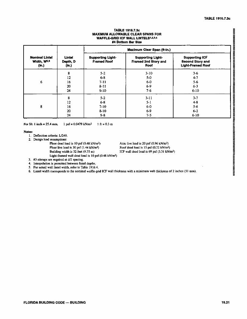
TABLE 1916.7.3~
TABLE 191 6.7.3~ MAXIMUM ALLOWABLE CLEAR SPANS FOR
WAFFLEGRID ICF WALL LiNTELS't2A4 #4 Bottom Bar Size
For SI: 1 inch = 25.4 mm, 1 psf = 0.0479 kNIm2 1 ft = 0.3 m
Notes: 1. Deflection criteria: U240. 2. Design load assumptions:
Floor dead load is 10 psf (0.48 kNlmZ) Attic live load is 20 psf (0.96 kNImZ) Floor live load is 30 psf (1.44 kNlm2) Roof dead load is 15 psf (0.72 kNIm2) Building width is 32 feet (9.75 m) ICF wall dead load is 69 psf (3.31 kNlm2) Light-framed wall dead load is 10 psf (0.48 kNlmZ)
3. #3 stirrups are required at dl2 spacing. 4. Interpolation is permitted between lintel depths. 5. For actual wall lintel width, refer to Table 1916.4. 6. Lintel width corresponds to the nominal waffle-grid ICF wall thickness with a minimum web thickness of 2 inches (51 mm).
Nominal Lintel Width, W5C
(in.)
6
8
.
FLORIDA BUILDING CODE - BUILDING
Lintel Depth, D
(in.)
8 12 16 20 24
8 12 16 20 24
Maximum Clear Span (ft-in.)
Supporting Light- Framed Roof
5-2 6-8 7-1 1 8-1 1 9-10
5-2 6-8 7-10 8-10 9-8
Supporting Light- Framed 2nd Story and
Roof
3-10 5-0 6-0 6-9 7-6
3-1 1 5-1 6-0 6-9 7-5
Supporting ICF Second Story and Light-Framed Roof
3-6 4-7 5-6 6-3 6-10
3-7 4-8 5-6 6-2 6-10
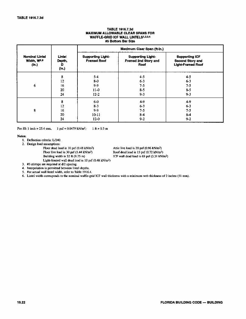
TABLE 1916.7.3d
TABLE 1916.7.3dMAXIMUM ALLOWABLE CLEAR SPANS FOR
WAFFLE-GRID ICF WALL LINTELS1,2,3,4
#5 Bottom Bar Size
Nominal LintelWidth, W5,6
(In.)
6
8
LintelDepth,
D(In.)
812162024
812162024
Maximum Clear Span (ft-in.)
Supporting Light-Framed Roof
5-48-09-911-012-2
6-08-39-9
10-1112-0
Supporting Light-Framed 2nd Story and
Roof
4-56-37-58-59-3
4-96-37-58-49-2
Supporting ICFSecond Story andLight-Framed Roof
4-56-37-58-59-3
4-96-37-58-49-2
For SI: 1 inch = 25.4 mm, 1 psf = 0.0479 kN/m2, 1 ft = 0.3 m
Notes:1. Deflection criteria: L/240.2. Design load assumptions:
Floor dead load is 10 psf (0.48 kN/m2)Floor live load is 30 psf (1.44 kN/m2)Building width is 32 ft (9.75 m)Light-framed wall dead load is 10 psf (0.48 kN/m2)
3. #3 stirrups are required at d/2 spacing.4. Interpolation is permitted between lintel depths.5. For actual wall lintel width, refer to Table 1916.4.6. Lintel width corresponds to the nominal waffle-grid ICF wall thickness with a minimum web thickness of 2 inches (51 mm).
Attic live load is 20 psf (0.96 kN/m2)Roof dead load is 15 psf (0.72 kN/m2)ICF wall dead load is 69 psf (3.31 kN/m2)
19.22 FLORIDA BUILDING CODE — BUILDING
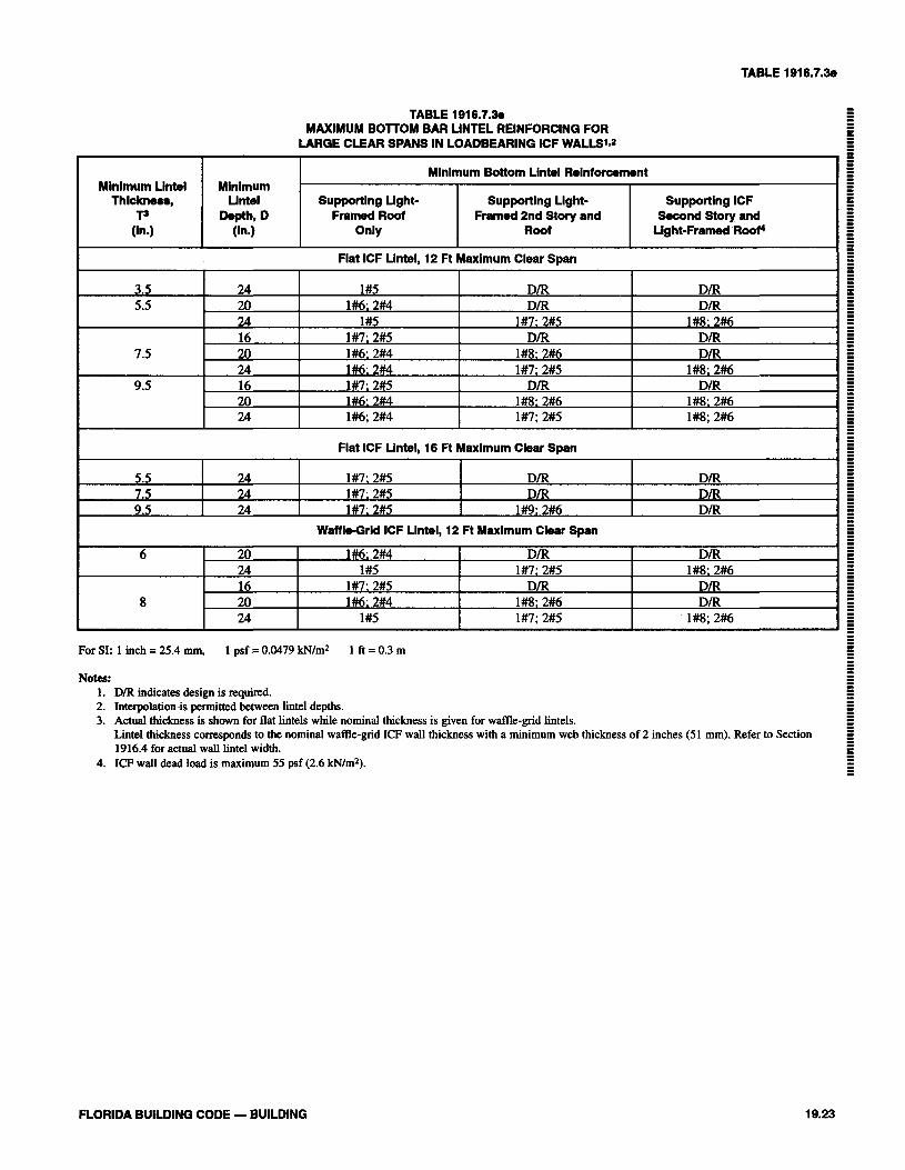
TABLE 191 6.7.38
TABLE 191 6.7.38 MAXIMUM BOlTOM BAR LINTEL REINFORCING FOR
LARGE CLEAR SPANS IN LOADBEARING ICF WALLS'J
For SI: 1 inch = 25.4 mm, 1 psf = 0.0479 kN/m2 1 !I = 0.3 m
Minlmum Lintel Thiclm(~e,
T3 (in.)
Notes: 1. D/R indicates design is required. 2. 1nterpolation.is permitted between lintel depths. 3. Actual thickness is shown for flat lintels while nominal thickness is given for waffle-grid lintels.
Lintel thickness corresponds to the nominal waffle-grid ICF wall thickness with a minimum web thickness of 2 inches (51 mm). Refer to Section 1916.4 for actual wall lintel width.
4. ICF wall dead load is maximum 55 psf (2.6 kN/m2).
FLORIDA BUILDING CODE - BUILDING
Mlnlmum Llntel
Dmh, D (In.)
Flat ICF Lintel, 12 Ft Maximum Clear Span
Mlnlmum Bottom Lintel Reinforcement
Supporting Light- Framed Roof
Only
3.5 5.5
7.5
9.5
24 20 24 16 20 24 16 20 24
1#5 1#6; 2#4
1#5 1#7: 2#5 1#6: 2#4 1#6; 2#4 1#7: 2#5 1%: 2#4 1#6; 2#4
Supporting Light- Framed 2nd Story and
Roof
Fiat ICF Llntel, 16 Ft Maxlmum Clear Span
Supporting ICF Second Story and
Light-Framed Roof4
D/R D/R
1#7; 2#5 D/R
1#8; 2#6 1#7: 2#5
D/R 1#8: 2#6 1#7; 2#5
D/R D m
1#8; 2#6 D/R D m
1#8; 2% D/R
1#8: 2#6 1#8; 2#6
5.5 7.5 9.5
24 24 24
1#7; 2#5 1#7: 2#5 1#7: 2#5
Waffle-Grid ICF Lintel, 12 Ft Maximum Clear Span
D/R D/R
1#9; 2%
D/R D/R D/R
6
8
1#6: 2#4 1#5
1#7: 2#5 1%: 2#4
1#5
20 24 16 20 24
D/R 1#7; 2#5
D/R 1#8: 2#6 1#7; 2#5
D/R 1#8; 2#6
D/R Dm
1#8; 2#6
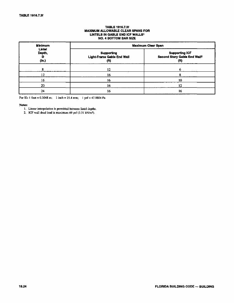
TABLE 1916.7.3f
TABLE 1916.7.3fMAXIMUM ALLOWABLE CLEAR SPANS FOR
LINTELS IN GABLE END ICF WALLS1
NO. 4 BOTTOM BAR SIZE
MinimumLintelDepth,
D(In.)
8
12
16
20
24
Maximum Clear Span
SupportingLight-Frame Gable End Wall
(ft)
12
16
16
16
16
Supporting ICFSecond Story Gable End Wall2
(ft)
6
8
10
12
16
For SI: 1 foot = 0.3048 m; 1 inch = 25.4 mm; 1 psf = 47.8804 Pa
Notes:1. Linear interpolation is permitted between lintel depths.2. ICF wall dead load is maximum 69 psf (3.31 kN/m2).
19.24 FLORIDA BUILDING CODE — BUILDING
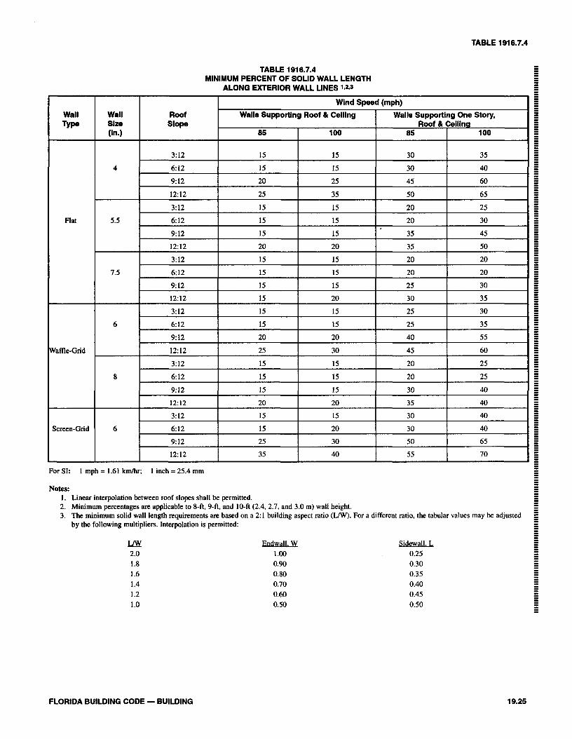
TABLE 191 6.7.4
TABLE 191 6.7.4 MINIMUM PERCENT OF SOLID WALL LENGTH
ALONG EXTERIOR WALL LINES 1,293
For SI: 1 mph = 1.61 kmthr; 1 inch = 25.4 mm
Wall TYP
Flat
Waffle-Grid
Screen-Grid
Notes: 1. Linear interpolation between roof slopes shall be permitted. 2. Minimum percentages are applicable to 8-ft.9-fi, and 10-ft (2.4.2.7, and 3.0 m) wall height. 3. The minimum solid wall length requirements are based on a 2:1 building aspect ratio (LIW). For a different ratio, the tabular values may be adjusted
by the following multipliers. Interpolation is permitted:
FLORIDA BUILDING CODE - BUILDING
Wall Slze (In.)
4
5.5
7.5
6
8
6
Roof Slope
3:12
6: 12
9:12
12:12
3:12
612
9:12
12:12
3:12
6:12
9: 12
12:12
3:12
6:12
9:12
12:12
3:12
6: 12
9:12
12:12
3:12
6:12
9:12
12:12
Wind Speed
Walls Supporting Roof 81 Ceiling (mph)
85
15
15
20
25
15
15
15
20
15
15
15
15
15
15
20
25
15
15
15
20
15
15
25
35
Walls Supporting Roof 81
85
30
30
45
50
20
20
35
35
20
20
25
30
25
25
40
45
20
20
30
35
30
30
50
55
100
15
15
25
35
15
15
15
20
15
15
15
20
15
15
20
30
15
15
15
20
15
20
30
40
One Story, Ceiling
100
35
40
60
65
25
30
45
50
20
20
30
35
30
35
55
60
25
25
40
40
40
40
65
70
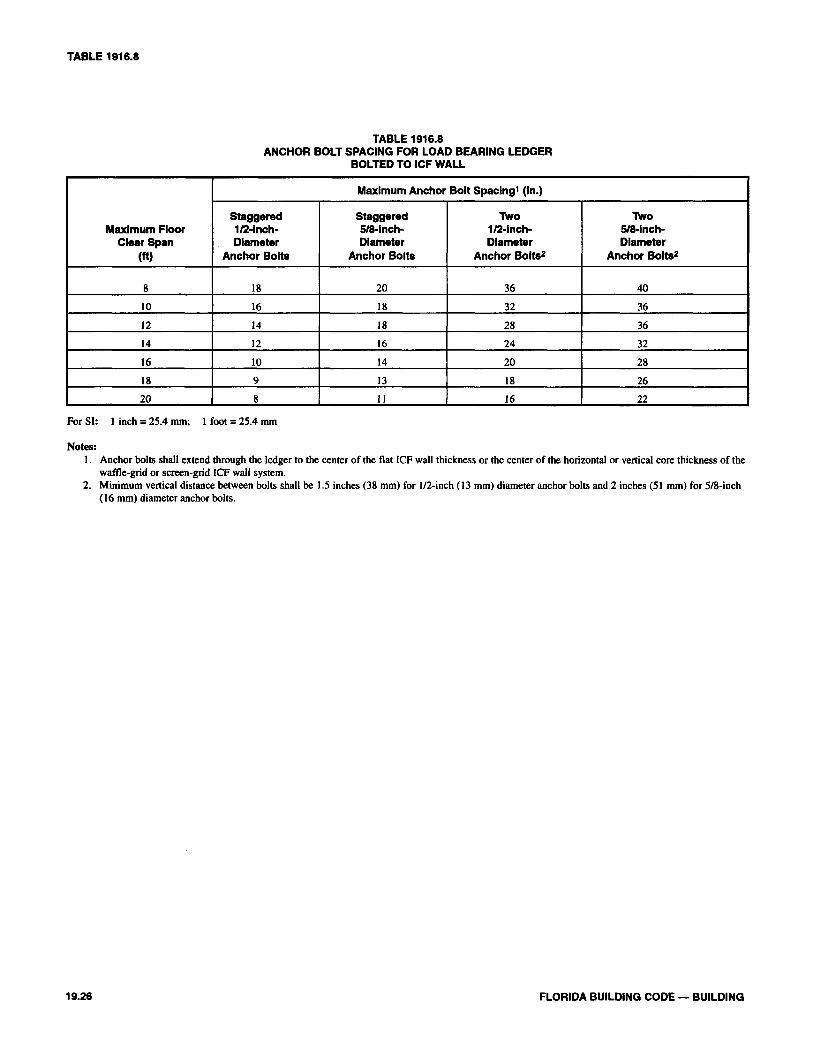
TABLE 1916.8
TABLE 1916.8ANCHOR BOLT SPACING FOR LOAD BEARING LEDGER
BOLTED TO ICF WALL
Maximum FloorClear Span
(ft)
8
10
12
14
16
18
20
Maximum Anchor Bolt Spacing1 (in.)
Staggered1/2-inch-Diameter
Anchor Bolts
18
16
14
12
10
9
8
Staggered5/8-inch-Diameter
Anchor Bolts
20
18
18
16
14
13
11
Two1/2-Inch-Diameter
Anchor Bolts2
36
32
28
24
20
18
16
Two5/8-lnch-Diameter
Anchor Bolts2
40
36
36
32
28
26
22
For SI: 1 inch = 25.4 mm; 1 foot = 25.4 mm
Notes:1. Anchor bolts shall extend through the ledger to the center of the flat ICF wall thickness or the center of the horizontal or vertical core thickness of the
waffle-grid or screen-grid ICF wall system.2. Minimum vertical distance between bolts shall be 1.5 inches (38 mm) for 1/2-inch (13 mm) diameter anchor bolts and 2 inches (51 mm) for 5/8-inch
(16 mm) diameter anchor bolts.
19.26 FLORIDA BUILDING CODE — BUILDING
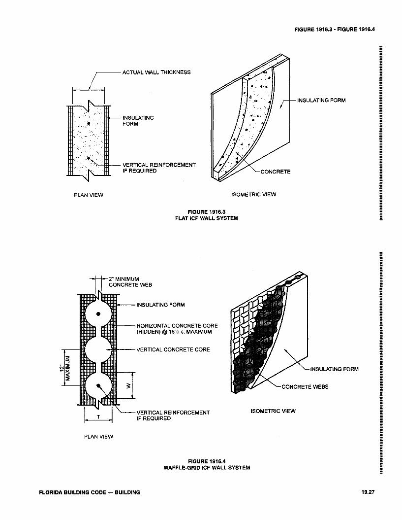
FIGURE 1916.3 - FIGURE 1916.4
ACTUAL W L L THICKNESS
PLAN VlEW
INSULATING FORM
VERTICAL REINFORCEMENT IF REQUIRED
ISOMETRIC VlEW
FIGURE 1916.3 FLAT ICF WALL SYSTEM
2 MINIMUM CONCRETE WEB
INSULATING FORM
HORIZONTAL CONCRETE CORE (HIDDEN) @ 1 6 0 . C . MAXIMUM
VERTICAL CONCRETE CORE
VERTICAL REINFORCEMENT
FORM
I-L--l IF REQUIRED
PLAN VlEW
FIGURE 1916.4 WAFFLE-GRID ICF WALL SYSTEM
FORM
ISOMETRIC VlEW
FLORIDA BUILDING CODE - BUILDING
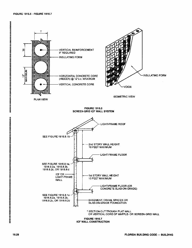
FIGURE 1916.5 - FIGURE 1916.7
VERTICAL REINFORCEMENT IF REQUIRED
INSULATING FORM
HORIZONTAL CONCRETE CORE (HIDDEN) @ 12o.c. MAXIMUM
VERTICAL CONCRETE CORE
ISOMETRIC VlEW PLAN VlEW
FIGURE 191 6.5 SCREEN-GRID ICF WALL SYSTEM
SEE FIGURE 1916.8.1a, 1916.8.2a, 1916.8.2b,
1916.8.2c, OR 1916.8.d
2nd STORY W L L HEIGHT 10 FEET MAXIMUM
1 s . I I 7 LIGHT-FRAME FLOOR
.INSULATING FORM
1st STORY WALL HEIGHT
WALL 10 FEET MAXIMUM
LIGHT-FRAME FLOOR (OR CONCRETE SLAB-ON-GRADE)
SEE FIGURE 1916.8.1a 1916.8.2a. 1916.8.2b,
1916.8.2~ OR 1916.8.24 BASEMENT, C R A M SPACES OR SLAB-ON-GRADE FOUNDATION
* SECTION CUTTROUGH FLAT WALL OR VERTICAL CORE OF WFFLE- OR SCREEN-GRID WALL
FIGURE 1916.7 ICF WALL CONSTRUCTION
FLORIDA BUILDING CODE - BUILDING

FIGURE 1916.7.2 - FIGURE 1916.7.3a
TOP OF WALL STORY
#4 CONTINUOUS BARAS REQUIRED IN1916.7.1
OPENING (TYP.)
#4 BAR AS REQUIREDIN 1916.7.2
#4 BAR, TYPICALIN ADDITION TO VERTICALREINFORCEMENT PER TABLE 1916.3
FIGURE 1916.7.2REINFORCEMENT OF OPENINGS
No. 4 BAR LINTEL REINFORCEMENTREQUIRED
— MINIMUM No. 3 STIRRUP AS REQUIRED
INSULATING FORM
HORIZONTAL LINTEL REINFORCEMENTAS REQUIRED
*SECTION CUT THROUGH FLAT WALL
FIGURE 1916.7.3aFLAT ICF LINTEL
FLORIDA BUILDING CODE — BUILDING 19.29
1-1/2" (38 mm) MINIMUM2-1/2" (64 mm) MAXIMUM
1-1/2" (38 mm) MINIMUM2-1/2" (64 mm) MAXIMUM
LINTEL REINFORCEMENT ASREQUIRED IN 1916.7.3
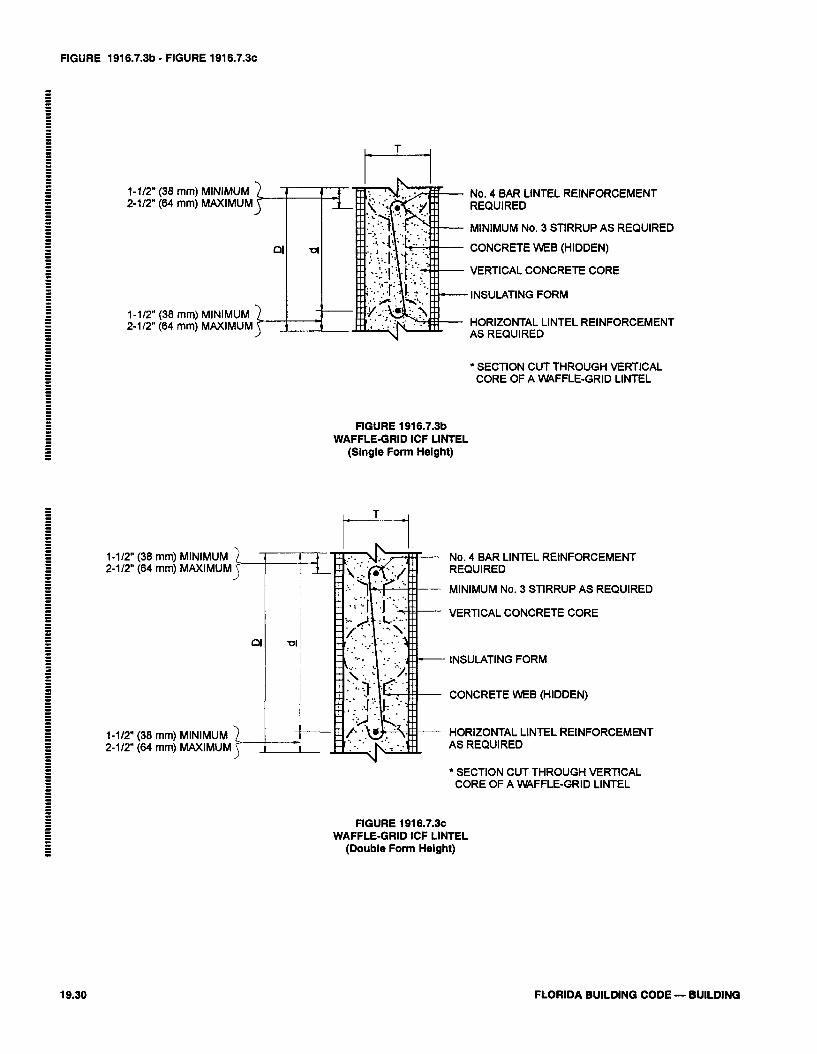
FIGURE 1916.7.3b - FIGURE 1916.7.3C
1-112" (38 mm) MINIMUM 2-112" (64 mm) MAXIMUM
1-112" (38 mm) MINIMUM 2-112" (64 mm) MAXIMUM
1-112" (38 mm) 2-112" (64 mm)
No. 4 BAR LINTEL REINFORCEMENT REQUIRED
MINIMUM No. 3 STIRRUP AS REQUIRED
CONCRETE WEB (HIDDEN)
VERTICAL CONCRETE CORE
INSULATING FORM
HORIZONTAL LINTEL REINFORCEMENT AS REQUIRED
* SECTION CUT THROUGH VERTICAL CORE OF A VWFFLE-GRID LINTEL
FIGURE 1916.7.3b WAFFLE-GRID ICF LINTEL
(Single Form Height)
No. 4 BAR LINTEL REINFORCEMENT REQUIRED
MINIMUM No. 3 STIRRUP AS REQUIRED
VERTICAL CONCRETE CORE
INSULATING FORM
CONCRETE WEB (HIDDEN)
HORIZONTAL LINTEL REINFORCEMENT AS REQUIRED
1-112" (38 mm) 2-112" (64 mm)
SECTION CUT THROUGH VERTICAL CORE OF A VWFFLE-GRID LINTEL
FIGURE 1916.7.3~ WAFFLE-GRID ICF LINTEL
(Double Form Helght)
FLORIDA BUILDING CODE - BUILDING

FIGURE 1916.8.1a - FIGURE 1916.8.1 b
- /- LIGHT-FRAME CONSTRUCTION
ANCHOR BOLT
MINIMUM #4 BAR (6ONTINUOUS)
* SECTION CUT THROUGH FLAT WALL OR VERTICAL CORE OF WAFFLE- OR SCREEN-GRID WALL
FIGURE 1916.8.1a SlLL PLATE CONNECTION
* SECTION CUT THROUGH FLAT WALL OR VERTICAL CORE OF WFFLE- OR SCREEN-GRID WALL
FIGURE 1916.8.1 b SlLL PLATE CONNECTION
FLORIDA BUILDJNG CODE - BUILDING
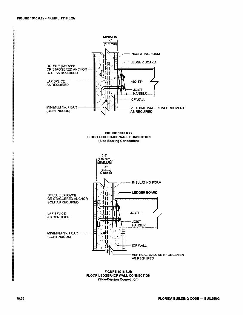
FIGURE 1916.8.2a - FIGURE 1916.8.2b
MINIMUM
k 1 i
DOUBLE (SHOWN) OR STAGGERED AN BOLT AS REQUIRED
LAP SPLICE AS REQUIRED
MINIMUM No. 4 BAR VERTICAL WALL REINFORCEMENT (CONTINUOUS) AS REQUIRED
FIGURE 1916.8.2a FLOOR LEDGER-ICF WALL CONNECTION
(Side-Bearing Connection)
- INSULATING FORM
DOUBLE (SHOWN) OR STAGGERED ANCHOR --
BOLT AS REQUIRED
LAP SPLICE ~ - -
AS REQUIRED
MINIMUM No. 4 BAR--- (CONTINUOUS)
VERTICAL WALL REINFORCEMENT AS REQUIRED
FIGURE 1916.8.2b FLOOR LEDGER-ICF WALL CONNECTION
(Side-Bearing Connection)
FLORIDA BUILDING CODE - BUILDING
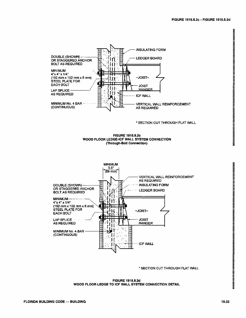
FIGURE 191 6.8.2C - FIGURE 191 6.8.2d
INSULATING FORM
DOUBLE (SHOWN) OR STAGGERED A BOLT AS REQUIRE
MINIMUM 4"x 4" x 114" (102mmx102mmx6mm) STEEL PLATE FOR EACH BOLT
LAP SPLICE AS REQUIRED
MINIMUM No. 4 BAR -- - - - VERTICAL WALL REINFORCEMENT (CONTINUOUS) AS REQUIRED
INSULATING FORM
OR STAGGERED ANCHOR BOLT AS REQUIRED
E$-- ICF WALL I
f f l VERTICAL WALL REINFORCEMENT
Y AS REQUIRED
' SECTION CUT THROUGH FLAT WALL
FIGURE 1916.8.2~ WOOD FLOOR LEDGE-ICF WALL SYSTEM CONNECTION
(Through-Bolt Connection)
' SECTION CUT THROUGH FLAT WALL
FIGURE 1916.8.2d WOOD FLOOR LEDGE TO ICF WALL SYSTEM CONNECTION DETAIL
FLORIDA BUILDING CODE - BUILDING
1917.2.2-1917.4.11
1917.2.2 The permit holder shall notify the BuildingOfficial 48 hours prior to the pouring of lightweight insu-lating concrete fill.
1917.2.3 The permit holder shall make available to theBuilding Official a job log with the following minimumitems.
1. Cast density recordings/hour2. Product evaluation for application3. Date and job locations identified4. Results of any field test conducted.
1917.2.4 The building official shall have clear access andclear path at his option for a walkability inspection of light-weight insulating concrete fill 24 hours after placement.
1917.3 Testing. The building official may require tests ofthe lightweight insulating concrete fill to confirm the fasten-er withdrawal resistance, compressive strength or drainageability.
1917.3.1 Existing roof assemblies to receive lightweightinsulating concrete fill other than galvanized G-90 steeldeck or structural concrete deck shall be tested for upliftfor adhesion to the substrate to confirm compliance withdesign pressure.
1917.4 Materials and limitations of use. Lightweight insu-lating concrete fill, in conjunction with galvanized formedsteel sheets, shall not be used as a roof deck in areas wherehighly corrosive chemicals are used or stored.
1917.4.1 Lightweight insulating concrete fill shall bepoured over bottom slotted galvanized (G-90) steel deck-ing as follows; cellular, 0.5 percent open; hybrid, 0.75 per-cent open, aggregate 1.5 percent open. No lightweightinsulating concrete shall be poured over a painted or non-galvanized steel deck.
1. Lightweight insulating concrete fill over structuralconcrete slabs, twin tees, precast units or other nonventing substrates shall be vented, to allow theescape of excess moisture
1917.4.2 Minimum thickness of lightweight insulatingconcrete fill shall be 2 inches over the top plane of thesubstrate unless otherwise specified in the ProductControl Approval. In all cases, lightweight insulating con-crete shall be of sufficient thickness to receive the specif-ic base ply fastener throughout the roof deck.
1917.4.3 Minimum compressive strength at 28 days shallbe as follows:
(1) Aggregate concrete 125 psi (5985 Pa)(2)Cellular type: nailed base sheet 160 psi (7661 Pa)(3)Cellular type: adhered
membrane systems 250 psi (11 970 Pa)
1917.4.4 Galvanized coatings of formed steel sheets shallbe in accordance with ASTM A 525 with a minimum coat-ing designation of G-90. Base steel shall conform toASTM A 446, grade A, B, C, D or greater and ASTM A611 C,D or E.
1917.4.5 Chemical admixtures shall be in compliancewith ASTM C 494. Calcium chloride or any admixturecontaining chloride salts shall not be used in insulatingconcrete. Fiber reinforcement may be used to controlcracking. Mineral admixtures shall conform to ASTM C618.
1917.4.6 Vermiculite or perlite shall be in compliancewith ASTM C 332, Group I. Foam concentrates shall be incompliance with ASTM C 796 and ASTM C 869.
1917.4.7 Mixing, placing and finishing shall be in com-pliance with the deck system Product Control Approval.Slurry coating, two-density casting and double castingshall be acceptable per the specific manufacturer's recom-mendations.
1917.4.8 If the lightweight insulating concrete deck is toreceive Product Control Approval for a direct-adheredroofing system, the deck surface shall be prepared to therequirements set forth in the roof system Product ControlApproval.
1917.4.9 All base ply fasteners for use in lightweight insu-lating concrete roof decks shall have a Product ControlApproval for use with the specific lightweight insulatingconcrete roof system in compliance with manufacturer'srecommendations and the design pressure of 1606.
1917.4.10 The lightweight insulating concrete fill fasten-er withdrawal shall have a minimum resistance for newpours of:
1. 60 pounds (267 N) in 28 days when the fastener isinstalled and allowed to age in the concrete.
2. 40 pounds (178 N) at time of roofing
1917.4.11 Lightweight insulating concrete fill systemexpansion joint shall be provided at the following loca-tions:
1. Where expansion or contraction joints are providedin the structural assembly
2. Where steel framing, structural steel, or deckingchange direction
3. Where separate wings of "L", "U", "T" or similarconfigurations exist
4. Where the type of decking changes (for example,where a precast concrete deck and a steel deck abut)
5. Whenever additions are connected to existing build-ings
19.34 FLORIDA BUILDING CODE — BUILDING
1917.4.12-1920.3
6. At junctions where interior heating conditionschange
7. Wherever differential movement between verticalwalls and the roof deck may occur.
1917.4.12 Insulation board with lightweight insulatingconcrete fill shall conform to Type I expanded polystyreneinsulation as defined in ASTM C 578.
1. Installation of insulating board in conjunction withlightweight insulating concrete shall comply withuplift requirements set forth in 1606. Insulationpanels shall be placed in a minimum 1/8 inch (3.2mm) slurry bed of insulating concrete while thematerial is still in a plastic state and shall be coveredwith insulating concrete within the same work dayof placement of the insulating panel. The minimum2 inch (51 mm) continuous pour is required so asnot to compromise the diagram design. Insulationpanels shall be provided with holes and/or slots forkeying and/or slots for venting.
1917.4.13 Reinforcing mesh shall be provided when nec-essary to meet fire-rating and/or special structural designrequirements. Refer to a specific Product ControlApproval for the specific requirements applicable to theproduct being installed.
1. Fibers may be added where control of plasticshrinkage and cracking is required. Refer to theProduct Control Approval for the specific require-ments applicable to the product being installed.
SECTION 1918SPECIAL WIND PROVISIONS FOR CONCRETE
1918.1 Reinforced concrete components. The design andconstruction of reinforced concrete components for buildingssited in areas with a basic wind speed greater than 100 mph(45 m/s) in accordance with Figure 1606 shall conform to therequirements of ACI 318 or with 1606.1.1, Exception 3 asapplicable, except as modified in this section.
1918.2 Insulated concrete form wall. Insulated concreteform (ICF) wall construction for buildings sited in areas witha basic wind speed of 100 mph (45 m/s) or less in accordancewith Figure 1606 shall be in accordance with 1916. Insulatedconcrete form (ICF) wall construction for buildings sited inareas with a basic wind speed greater than 100 mph (45 m/s)in accordance with Figure 1606 shall be in accordance withACI 318 or with 1606.1.1, Exception 3 as applicable.
1918.3 Gable endwalls.1918.3.1 General. Gable endwalls shall be structurallycontinuous between points of lateral support.
1918.3.2 Cathedral endwalls. Gable endwalls adjacent tocathedral ceilings shall be continuous from the uppermostfloor to ceiling diaphragm or to the roof diaphragm.
SECTION 1919HIGH VELOCITY HURRICANE ZONES
GENERAL
1919.1 Scope. This section prescribes requirements for rein-forced concrete in construction regulated by this code.
1919.2 Application. Reinforced concrete shall be of thematerials, proportions strength and consistency as set forth inthis section and shall be designed by methods admitting ofrational analysis according to established principles ofmechanics.
1919.3 Requirements. All structures of reinforced concrete,including prestressed concrete, shall be designed and con-structed in accordance with the provisions of ACI 318 asadopted herein.
1919.4 Workmanship. Concrete construction shall be inconformance with the tolerance, quality and methods of con-struction set forth in 1920.
SECTION 1920HIGH VELOCITY HURRICANE ZONES
STANDARDS
1920.1 The following Standards are hereby adopted as part ofthis code as set forth in Chapter 35 of this code.
1920.2 American Concrete Institute (ACI).1. Standard Tolerances for Concrete Construction and
Materials, ACI 117.2. Specifications for Structural Concrete for Buildings,
ACI 301.3. Manual of Standard Practice for Detailing Reinforced
Concrete Structures, ACI 315.4. Building Code Requirements for Reinforced Concrete,
ACI 318.5. Recommended Practice for Concrete Formwork, ACI
347.6. Recommended Practice for Shotcreting, ACI 506.7. Specification for Materials, Proportioning, and
Application of Shotcrete, ACI 506.2.8. Deformed and Plain Billet Steel Bars for Concrete
Reinforcement, ASTM A615, including SI.
1920.3 American National Standards Institute(ANSI)/American Society of Civil Engineers (ASCE).
1. Specifications for the Design and Construction ofComposite Slabs and Commentary on Specificationsfor the Design and Construction of Composite Slabs,ANSI/ASCE 3.
FLORIDA BUILDING CODE — BUILDING 19.35

1920.4-1922.4.1
2. Guideline for Structural Assessment of ExistingBuildings, ANSI/ASCE 11.
1920.4 American Society for Testing Materials (ASTM).1. Deformed and Plain Billet Steel Bars for Concrete
Reinforcement, ASTM A 615, including.S1.2. Testing Concrete Aggregates for Use in Construction
and Criteria for Laboratory Evaluation, ASTM C 1077.
SECTION 1921HIGH VELOCITY HURRICANE ZONES
DEFINITIONS
1921.1 The following definitions apply to the provisions ofSection 1919 through 1929.
Plain Concrete. Concrete that is either unreinforced orcontains less reinforcement than the minimum amountspecified for reinforced concrete.
Reinforced Concrete. Concrete reinforced with no lessthan the minimum amount required by ACI 318, pre-stressed or non-prestressed, and designed on the assump-tion that the two materials act together in resisting forces.
Prestressed Concrete. Reinforced concrete in whichinternal stresses have been introduced to reduce potentialtensile stresses in concrete resulting from loads, The termprestressed concrete refers to pretensioned concrete inwhich the reinforcing is tensioned before hardening of theconcrete, to postensioned concrete in which the reinforc-ing is tensioned after hardening of the concrete, or combi-nations of both pretensioning and posttensioning.
Precast Concrete. Plain or reinforced concrete elementscast elsewhere than their final position in a structure.
Shotcrete. Mortar or concrete pneumatically projected athigh velocity onto a surface.
SECTION 1922HIGH VELOCITY HURRICANE ZONES
MATERIALS
1922.1 Cements. Cements shall conform to one of the fol-lowing specifications for portland cement as set forth inChapter 35.
1. Portland Cement, ASTM C 1502. Blended Hydraulic Cements, ASTM C 595, excluding
Types S and SA, which are not intended as principalcementing constituents of structural concrete.
1922.2 Aggregates for concrete shall conform to one of thefollowing specifications as set forth in Chapter 35 of thiscode or Paragraph 1922.2.1.
1. Concrete Aggregates, ASTM C 33.2. Lightweight Aggregates for Structural Concrete,
ASTM C330.
1922.2.1 Gradation of locally produced sand and crushedrock aggregate shall be as follows:
COARSE AGGREGATEPercent Passing
10095 - 100
25-600 - 10
0 - 5
1-1/2"1"1/2"#4#8
sievesievesievesievesieve
FINE AGGREGATEPercent
3/8"#4#8#16#30#50#100
Passing
sievesievesievesievesievesievesieve
10090 - 10070-9550-8530-7010-450- 10
1922.2.2 Aggregates failing to meet ASTM C 33, ASTMC 330 or the above special gradation but which havebeen shown by special test or actual service to produceconcrete of adequate strength and durability may be usedwhen certified by the engineer.
1922.2.3 Aggregates shall be quarried or washed in freshwater and shall contain not more than 1/20 of 1 percentsalt by weight.
1922.3 Water used in mixing concrete shall be clean and freefrom injurious amounts of oils, acids, alkalis, salts, organicmaterials or other substances that may be deleterious to con-crete or reinforcement.
1922.3.1 Mixing water for concrete, including that portionof mixing water contributed in the form of free moistureon aggregates, shall not contain deleterious amounts ofchloride ion.
1922.4 Reinforcement:1922.4.1 Deformed reinforcement shall conform to one ofthe specifications as set forth in Chapter 35, except as pro-vided in Section 3.5 of ACI 318.
19.36 FLORIDA BUILDING CODE — BUILDING
1922.4.2-1923.2.1.2
1922.4.2 Prestressing tendons shall conform to one of thespecifications as set forth in Chapter 35.
Exception: Wire strands and bars not specifically list-ed in ASTM A 421, A 416, or A 722 may be used pro-vided they conform to minimum requirements of thesespecifications and do not have properties that makethem less satisfactory than those listed in ASTM A 416,A 421 or A 722.
1922.4.3 Reinforcement consisting of structural steel,steel pipe or steel tubing may be used as specified in ACI318.
1922.4.4 All welding of reinforcement shall conform tothe Structural Welding Code—Reinforcing Steel, AWSD1.4, as set forth in Chapter 35.
1922.4.5 Reinforcement to be welded shall be indicatedon the drawings, and welding procedures to be used shallbe specified. ASTM steel specifications, except ASTM A706, shall be supplemented to require a report of materialproperties necessary to conform to welding proceduresspecified in AWS D1.4.
1922.4.6 Deformed reinforcement may be galvanized orepoxy-coated in accordance with the Specifications forZinc-Coated (galvanized) Bars for Concrete reinforce-ment, ASTM A 767 or the Specification for Epoxy-CoatedBars, ASTM A 775. Zinc or epoxy-coated reinforcementshall conform to ASTM A 615, A 616 (S1), A 617 or A706.
1922.5 Admixtures:1922.5.1 Admixtures to be used in concrete shall conformto one of the specifications set forth in Chapter 35.
1922.5.2 An admixture shall be shown capable of main-taining essentially the same composition and performancethroughout the work as the product used in establishingconcrete proportions.
1922.5.3 Admixtures containing chloride ions shall not beused in concrete if their use will produce a deleteriousconcentration of chloride ion in the mixing water.
1922.6 Test of materials.1922.6.1 The building official, or his authorized represen-tative, shall have the right to order the test of any materi-al entering into concrete or reinforced concrete to deter-mine its suitability for the purpose; to order reasonabletests of the concrete from time to time to determinewhether the materials and methods in use are such as toproduce concrete of the necessary quality; and to order thetest under load of any portion of a completed structure
when conditions have been such as to leave doubt as to theadequacy of the structure to serve the purpose for which itis intended.
1922.6.2 Materials and of concrete shall be tested inaccordance with applicable standards of the AmericanSociety for Testing Materials (ASTM) as listed in Chapter35. Tests shall be made by an approved testing laboratoryand results of such tests shall be submitted to the buildingofficial. Approved testing laboratories shall comply withASTM C 1077.
1922.6.3 A complete record of tests of materials and ofconcrete shall be available to the building official forinspection during progress of work and for 5 years aftercompletion of the project, and shall be preserved by theinspecting engineer or architect for that purpose.
1922.6.4 If doubt develops concerning the safety of astructure or member, the building official may order astructural strength investigation by analysis or by meansof load tests, or by a combination of analyses and load testas set forth in Chapter 20 of ACI 318.
SECTION 1923HIGH VELOCITY HURRICANE ZONES
CONCRETE QUALITY
1923.1 General1923.1.1 Concrete shall be proportioned and produced toprovide an average compressive strength sufficiently highto minimize the frequency of strength test below the spec-ified compressive strength of concrete, f 'c.
1923.1.2 Requirements for f 'c shall be based on tests ofcylinders made and tested as prescribed in 1923.2.2.3.
1923.1.3 Unless otherwise specified, f 'c shall be based on28-day tests. If other than 28-day tests are called for, f 'cshall be indicated in design drawings or specifications.
1923.1.4 Design drawings shall show the specified com-pressive strength of concrete, f 'c for which each part ofthe structure is designed.
1923.2 Evaluation and acceptance concrete.1923.2.1 Frequency of testing.
1923.2.1.1 The building official may require a reason-able number of tests to be made during the progress ofthe work, or may promulgate and set forth in writingsuch reasonable rules for requiring tests to be made byan approved laboratory as he may consider necessaryto insure compliance with this code.
1923.2.1.2 Not less than 3 specimens shall be made foreach standard test.
FLORIDA BUILDING CODE — BUILDING 19.37
1923.2.1.3-1923.2.4.4
1923.2.1.3 Samples for strength of each class of con-crete placed each day shall be taken not less than oncea day, nor less than once for each 150 cubic yard (4.3m3) of concrete, nor less than once for each 5000 sq ft(465 m2) of surface area for slabs or walls.
1923.2.1.4 On a given project, if total volume of con-crete is such that frequency of testing required by1923.2.1.1 would provide less than 5 strength tests fora given class of concrete, tests shall be made from atleast 5 randomly selected batches or from each batch iffewer than 5 batches are used.
1923.2.1.5 Test cylinders taken on truck-mixed con-crete shall be taken at the approximate one-quarterpoint of the load.
1923.2.1.6 The age for strength tests shall be 28 days,or where specified, at the earlier age at which the con-crete is to receive its full working load.
1923.2.2 Laboratory cured specimens:1923.2.2.1 A strength test shall be the average of thestrengths of two cylinders made from the same sampleof concrete and tested at 28 days or at a test age desig-nated for determination of f 'c.
1923.2.2.2 Samples of strength tests shall be taken inaccordance with the Method of Sampling FreshConcrete, ASTM C 172, as set forth in Chapter 35.
1923.2.2.3 Cylinders for strength tests shall be moldedand laboratory-cured in accordance with the Method ofmaking and Curing Concrete Test Specimens in theField, ASTM C 31, as set forth in Chapter 35 of thiscode, and tested in accordance with the Method of Testfor Compressive Strength of Cylindrical ConcreteSpecimens, ASTM C 39, as set forth in Chapter 35.
1923.2.2.4 The strength level of an individual class ofconcrete shall be considered satisfactory if both of thefollowing requirements are met:
1. Average of all sets of 3 consecutivestrength tests equal or exceed f 'c
2. No individual strength test (average of 2cylinders) falls below f 'c by more than 500psi (3448 kPa).
1923.2.2.5 If any of the requirements of 1923.2 are notmet, steps shall be taken to increase the average of sub-sequent strength test results. Requirements of 1923.2.4shall be observed if any individual strength test fallsbelow f 'c by more than 500 psi (3448 kPa).
1923.2.3 Field cured specimens.1923.2.3.1 The building official may require strengthtests of cylinders cured under field conditions to checkadequacy of curing and protection of concrete in thestructure.
1923.2.3.2 Field-cured cylinders shall be cured underfield conditions in accordance with Section 7.4 of theMethod of Making and Curing Concrete Test speci-mens in the Field, ASTM C 31.
1923.2.3.3 Field-cured test cylinders shall be molded atthe same time and from the same samples as laborato-ry-cured test cylinders.
1923.2.3.4 Procedures for protecting and curing con-crete shall be improved when the strength of field- curedcylinders at test age designated for determination of f 'cis less than 85 percent of that of companion laboratorycured cylinders. The 85 percent may be waived if fieldcured strength exceeds f 'c by more than 500 psi (3448Pa).
1923.2.4 Investigation of low strength test results.1923..2.4.1 When there is a question as to the qualityof the concrete in the structure, the building officialmay require core tests in accordance with the StandardMethod of Obtaining and Testing Drilled Cores andSawed Beams of Concrete, ASTM C 42, as set forth inChapter 35 of this code, or order load tests on that por-tion of the structure where the questionable concretehas been placed.
1923.2.4.2 When concrete in structures has failed tomeet the minimum standard, the building official shallorder analysis and reports by a Registered Engineer todetermine the adequacy of the structure.
1923.2.4.3 If the likelihood of low-strength concrete isconfirmed and computations indicate that load-carry-ing capacity may have been significantly reduced, testsof cores drilled from the area in question may berequired in accordance with the Method of Obtainingand Testing Drilled Cores and Sawed Beams ofConcrete, ASTM C 42, as set forth in Chapter 35 of thiscode. In such case, 3 cores shall be taken for eachstrength test more than 500 psi (3448 kPa) below spec-ified value of f 'c.
1923.2.4.4 If concrete in the structure will be dry underservice conditions, cores shall be air dried at a temperaturebetween 60°F and 80°F and a relative humidity less than60 percent for 7 days before testing and shall be tested dry.If concrete in the structure will be more than superficiallywet under service conditions, cores shall be immersed inwater for at least 40 hours and be tested wet.
19.38 FLORIDA BUILDING CODE — BUILDING
1923.2.4.5 - 1924.4.7
1923.2.4.5 Concrete in an area represented by coretests shall be considered structurally adequate if theaverage of three cores is equals to at least 85% of f 'cand if no single core is less than 75 percent of f 'c. Tocheck testing accuracy, locations represented by erraticcore strengths may be retested.
1923.2.4.6 Slump considerations. The maximumallowable slump of concrete shall be 6 inches (152mm). On the jobs controlled and supervised by aProfessional Engineer, this maximum may be exceed-ed, but no concrete shall exceed the slump as indicatedon the approved plans for proposed work.
SECTION 1924HIGH VELOCITY HURRICANE ZONES
MIXING AND PLACING CONCRETE
1924.1 Preparation of equipment and place of deposit.1924.1.1 Preparation before concrete placement shallinclude the following:
1. All equipment for mixing and transporting concreteshall be clean.
2. All debris shall be removed from the spaces to beoccupied by the concrete.
3. Forms shall be properly coated.4. Masonry filler units that will be in contact with con-
crete shall be well drenched.5. Reinforcement shall be thoroughly cleaned of dele-
terious coatings.6. Water shall be removed from place of deposit before
concrete is placed unless a tremie is to be used orunless otherwise permitted by the ProfessionalEngineer.
7. All laitance and other unsound material shall beremoved before additional concrete is placedagainst hardened concrete.
1924.2 Mixing.1924.2.1 All concrete shall be mixed until there is uniformdistribution of materials and shall be discharged com-pletely before the mixer is recharged.
1924.2.2 Ready-mixed concrete shall be mixed and deliv-ered in accordance with requirements of theSpecifications for Ready-Mixed Concrete, ASTM C 94, orthe Specifications for Concrete made by VolumetricBatching and Continuous Mixing, ASTM C 685, as setforth in Chapter 35 of this code.
1924.2.3 Job-mixed concrete shall be mixed in accor-dance with the following:
1. Mixing shall be done in a batch mixer of approvedtype.
2. Mixer shall be rotated at a speed recommended bythe manufacturer.
3. Mixing shall be continued for at least 1-1/2 minutesafter all materials are in the drum, unless a shortertime is shown to be satisfactory by the mixing uni-formity test of Specification for Ready-MixedConcrete, ASTM C 94.
4. Materials handling, batching, and mixing shall con-form to applicable provisions of the Specificationsfor Ready-Mixed Concrete, ASTM C 94.
5. A detailed record shall be kept to identify:5.1 Number of batches produced.5.2 Proportions of materials used.5.3 Approximate location of final deposit in
structure.5.4 Time and date of mixing and placing.
1924.3 Conveying.1924.3.1 Concrete shall be conveyed from mixer to theplace of final deposit by methods that will prevent separa-tion or loss of the materials.
1924.3.2 Conveying equipment shall be capable of pro-viding a supply of concrete at the site of placement with-out separation of ingredients and without interruptionssufficient to permit loss of plasticity between successiveincrements.
1924.4 Depositing.1924.4.1 Concrete shall be deposited as nearly as practi-cable in its final position to avoid segregation caused byrehandling or flowing.
1924.4.2 Concreting shall be carried on at such a rate thatconcrete is at all times plastic and flows readily into thespaces between reinforcement.
1924.4.3 Concrete that has partially hardened or been con-taminated by foreign materials shall not be deposited inthe structure.
1924.4.4 Retempered concrete or concrete that has beenremixed after initial set shall not be used unless approvedby the building official.
1924.4.5 After concreting is started, it shall be carried onas a continuous operation until placing of the panel or sec-tion, as defined by its boundaries or predetermined jointsis completed except as permitted or prohibited by 1925.4.
1924.4.6 Top surfaces of vertically formed lifts shall begenerally level.
1924.4.7 When construction joints are required, jointsshall be made in accordance with 1925.4.
FLORIDA BUILDING CODE — BUILDING 19.39
1924.4.8-1925.2.3
1924.4.8 All concrete shall be thoroughly consolidated bysuitable means during placement and shall be thoroughlyworked around the reinforcement and embedded fixturesand into corners of forms.
1924.5 Curing.1924.5.1 Concrete, other than high-early-strength, shall bemaintained in a moist condition for as least the first 7 daysafter placement, except when cured in accordance with1924.5.3.
1924.5.2 High-early-strength concrete shall be maintainedin a moist condition for at least the first 3 days, exceptwhen cured in accordance with 1924.5.3.
1924.5.3 Accelerated curing:1. Curing by high pressure steam, steam at atmospher-
ic pressure, heat and moisture, or other acceptedprocesses, may be employed to accelerate strengthgain and reduce time of curing.
2. Accelerated curing shall provide a compressivestrength of the concrete at the load stage consideredat least equal to required design strength at that loadstage.
3. The curing process shall produce concrete with adurability at least equivalent to the curing method of1924.5.3, item 1 or 2.
4. Supplementary strength tests in accordance with1923.2.3 may be required to assure that curing issatisfactory.
1924.6 Bonding.1924.6.1 Before fresh concrete is deposited or placed onor against concrete which has hardened for 8 hours orlonger, the forms shall be re-tightened, the surface of thehardened concrete shall be cleaned of all foreign matterand laitance, and dampened, but not saturated. Fresh con-crete shall not be deposited or placed on or against hard-ened concrete so dampened before the surface is com-pletely free of shiny spots indicating free moisture. Whenthe concrete against which fresh concrete will be placed isless than 8 hours old, all laitance, loose particles and dirtshall be removed.
1924.6.2 Where bonding of fresh to hardened concrete isnecessary, construction joints and joints between footingsand walls or columns, between walls or columns andbeams or floors they support, and joints in unexposedwalls shall be accomplished by reinforcement, dowels,adhesives, mechanical connectors or other approvedmethods. Hardened concrete at joints shall be dampened,but not saturated, immediately prior to the placement offresh concrete.
SECTION 1925HIGH VELOCITY HURRICANE ZONESFORMWORK, EMBEDDED PIPES AND
CONSTRUCTION JOINTS
1925.1Design of formwork.1925.1.1 Forms shall be designed in accordance with ACI347, Recommended Practice for Concrete Formwork.
1925.1.2 Forms shall result in a final structure that con-forms to shapes, lines and dimensions of the members asrequired by the design drawings and specifications.
1925.1.3 Forms shall be substantial and sufficiently tightto prevent leakage of mortar.
1925.1.4 Forms shall be properly braced or tied togetherto maintain position and shape.
1925.1.5 Forms and their supports shall be designed so asnot to damage previously placed structures.
1925.1.6 Design of formwork shall include considerationof the rate and method of placing concrete; constructionloads, including vertical, horizontal and impact loads; andspecial form requirements for construction of shells, fold-ed plates, domes, architectural concrete or similar types ofelements.
1925.1.7 Forms for prestressed concrete members shall bedesigned and constructed to permit movement of themember without damage during application of prestress-ing force.
1925.2 Removal of forms and shores.1925.2.1 No construction loads shall be supported on, norany shoring removed from, any part of the structure underconstruction except when that portion of the structure incombination with the remaining forming and shoring sys-tem has sufficient strength to safely support its weight andloads placed thereon.
1925.2.2 Sufficient strength shall be demonstrated bystructural analysis considering proposed loads, strength ofthe forming and shoring system and concrete strengthdata. Concrete strength data may be based on tests offield-cured cylinders or, when approved by the buildingofficial, on other procedures to evaluate concrete strength.Structural analysis and concrete strength test data shall befurnished to the building official when so required.
1925.2.3 No construction loads exceeding the combina-tion of superimposed dead load plus specified live loadshall be supported on any unshored portion of the struc-ture under construction, unless analysis indicated ade-quate strength to support such additional loads.
19.40 FLORIDA BUILDING CODE — BUILDING
1925.2.4 -1925.4.1
1925.2.4 Forms shall be removed in a manner that doesnot impair the safety and serviceability of the structure.All concrete to be exposed by form removal shall havesufficient strength not to be damaged thereby.
1925.2.5 Form supports for prestressed concrete membersmay be removed when sufficient prestressing has beenapplied to enable prestressed members to carry their deadload and anticipated construction loads.
1925.3 Conduits and pipes embedded in concrete.1925.3.1 Conduits, pipes and sleeves of any material notharmful to concrete, and with limitations of this section,may be embedded in concrete with approval of theProfessional Engineer provided they are not considered tostructurally replace the displaced concrete.
1925.3.2 Conduits or pipes of aluminum shall not beembedded in structural concrete unless effectively coatedor covered to prevent aluminum-concrete reaction or elec-trolytic action between aluminum and steel.
1925.3.3 Conduits, pipes and sleeves passing through aslab, wall or beam shall not impair the strength of the con-struction.
1925.3.4 Conduits and pipes, with their fittings, embed-ded within a column shall not displace more than 4% ofthe area of cross section on which strength is calculated orwhich is required for fire protection.
1925.3.5 Except when plans for conduits and pipes areapproved by the Professional Engineer and other thanthose merely passing through, conduits and pipes embed-ded within a slab, wall or beam shall satisfy the following:
1. They shall not be larger in outside dimension than3/8 of the overall thickness of slab, wall or beam inwhich they are embedded.
2. They shall not be spaced closer than 3 diameters orwidths on center.
3. They shall not impair the strength of the construc-tion.
1925.3.6 Conduits, pipes and sleeves may be consideredas replacing structurally in compression the displacedconcrete, provided:
1. They are not exposed to rusting or other deteriora-tion.
2. They are of uncoated or galvanized iron or steel notthinner than standard Schedule 40 steel pipe, and
3. They have a nominal inside diameter not over 2inches (51 mm) and are spaced not less than 3 diam-eters on centers.
1925.3.7 In addition to other requirements of 1925.3 pipesthat will contain liquid, gas or vapor may be embedded instructural concrete under the following conditions:
1. Pipes and fittings shall be designed to resist effectsof the material, pressure and temperature to whichthey will be subjected.
2. Temperature of liquid, gas or vapor shall not exceed150°F (66°C).
3. Maximum pressure to which any piping or fittingsshall be subjected shall not exceed 200 psi (1379kPa) above atmospheric pressure.
4. All piping and fittings except as provided in1925.3.5 shall be tested as a unit for leaks beforeconcrete placement. Testing pressure above atmos-pheric pressure shall be 50 percent in excess of pres-sure to which piping and fittings may be subjected,but minimum testing pressure shall not be less than150 psi (1034 kPa) above atmospheric pressure.Pressure test shall be held for 4 hours with no dropin pressure except that which may be caused by airtemperature.
5. Drain pipes and other piping designed for pressuresof not more than 1 psi (7 kPa) above atmosphericpressure need not be tested as required in1925.3.7(4).
6. Pipes carrying liquid, gas or vapor that is explosiveor injurious to health shall be tested again as speci-fied in 1925.3.7(4) after concrete has hardened.
7. No liquid, gas or vapor, except water not exceeding90°F (32°C) nor 50 psi (350 kPa) pressure, shall beplaced in the pipes until the concrete has attained itsdesign strength.
8. In solid slabs the piping, unless it is for radiant heat-ing, shall be placed between top and bottom rein-forcement.
9. Concrete cover for pipes and fittings shall not beless than 11/2 inches (38 mm) for concrete exposedto earth or weather, nor 3/4 inch (19 mm) for con-crete not exposed to weather or in contact withground.
10. Reinforcement with an area not less than 0.002times the area of concrete section shall be providednormal to the piping.
11. Piping and fittings shall be assembled by welding,brazing, solder sweating or other equally satisfacto-ry methods. Screw connections shall not be permit-ted. Piping shall be so fabricated and installed thatcutting, bending or displacement of reinforcementfrom its proper location will not be required.
1925.4 Construction joints.1925.4.1 Surfaces of the concrete construction joints shallbe cleaned and laitance removed.
FLORIDA BUILDING CODE — BUILDING 19.41
1925.4.2-1926.4.1
1925.4.2 Immediately before new concrete is placed, allconstruction joints shall be wetted and standing waterremoved.
1925.4.3 Construction joints shall be so made and locatedas not to impair the strength of the structure. Provisionshall be made for transfer of shear and other forcesthrough construction joints.
1925.4.4 Construction joints in floors shall be located nearthe middle of the spans of slabs, beams or girders, unlessa beam intersects a girder at the middle location, in whichcase, joints in the girders shall be offset a distance approx-imately twice the width of the beam.
1925.4.5 Beams, girders or slabs supported by columns orwalls shall not be cast or erected until concrete in the ver-tical support members is no longer plastic.
1925.4.6 Beams, girders, haunches, drop panels and capi-tals shall be placed monolithically as part of a slab system,unless otherwise shown on design drawing.
SECTION 1926HIGH VELOCITY HURRICANE ZONES
DETAILS OF REINFORCEMENT
1926.1 Bending reinforcement.1926.1.1 All reinforcement shall be bent cold, unless oth-erwise permitted by the Professional Engineer.
1926.1.2 Reinforcement partially embedded in concreteshall not be field bent, except as shown on the designdrawings or permitted by the Professional Engineer.
1926.2 Surface conditions of reinforcement1926.2.1 At the time concrete is placed, reinforcementshall be free from mud, oil or other nonmetallic coatingsthat adversely affect bonding capacity.
1926.2.2 Steel reinforcement, except prestressing tendons,with rust, mill scale or a combination of both shall be con-sidered satisfactory, provided the minimum dimensions,including the height of deformations and weight of ahand-wire-brushed test specimen, are not less than applic-able ASTM specification requirements.
1926.2.3 Prestressing tendons shall be clean and free ofoil, dirt, scale, pitting and excessive ruts. A light oxide ispermissible.
1926.3 Placing reinforcement.1926.3.1 Steel reinforcement shall be accurately placedand adequately secured in position by concrete or metalchairs or spacers or other acceptable methods. The mini-
mum clear distance between parallel bars, except incolumns, shall be equal to the nominal diameter of thebars. In no case shall the clear distance between bars beless than 1 inch (25 mm), or less than 1 1/3 times the max-imum size of the coarse aggregate. When reinforcement inbeams or girders is placed in 2 or more layers, the cleardistance between layers shall not be less than 1 inch (25mm) nor less than the diameter of the bars, and the bars inthe upper layers shall be placed directly above those in thebottom layer.
1926.3.2 Unless otherwise permitted by the building offi-cial and Professional Engineer, reinforcement, prestress-ing tendons and prestressing ducts shall be placed withinthe following tolerances:
1. Tolerance for depth, d, and minimum concrete coverin flexural members, walls and compression mem-bers shall be as follows, where d represents the dis-tance from the extreme compression fiber to thecentroid of the tension reinforcement:
d < 8 in.d > 8 in.
Toleranceon "d"
± 3/8 in.± 1/2 in.
Toleranceon minimum
concrete cover- 3/8 in.- 1/2 in.
Exceptions:a. Tolerance for the clear distance to formed sof-
fits shall be minus 1/4 inch (-6.3 mm).b. Tolerance for cover shall not exceed minus 1/3
the minimum concrete cover required in thecontract drawings nor less than 1 inch (25mm) when exposed to weather.
2. Tolerance for longitudinal location of bends andends of reinforcement shall be + 2 inches (+ 102mm) except at discontinuous ends of memberswhere tolerance shall be + l/2 inch (+ 12.7 mm).
1926.3.3 Welded wire fabric with a wire size not greaterthan W5 or D5 used in slabs not exceeding 10 feet (3 m)in span may be curved from a point near the top of the slabover the support to a point near the bottom of the slab atmidspan, provided such reinforcement is either continu-ous over, or securely anchored at, the support.
1926.3.4 Welding of crossing bars shall not be permittedfor assembly of reinforcement unless approved by theProfessional Engineer of Record.
1926.3.5 Spacing limits and concrete cover for reinforce-ment shall be shown on the design drawings.
1926.4 Splices in reinforcement.1926.4.1 In slabs, beams and girders, splices in reinforce-ment at points of maximum stress shall be avoided wher-
19.42 FLORIDA BUILDING CODE — BUILDING

1926.4.2-1926.5.6
ever possible. Such splices, where used, shall be welded,lapped or otherwise fully developed, but, in any case, shalltransfer the entire stress from bar to bar without exceedingthe allowable bond and shear stresses. The minimumoverlap for a lapped splice shall be 24 bar diameters, butnot less than 12 inches (25 mm) for bars and in accordancewith Section 12.15 and 12.16 of ACI 318. The clear dis-tance between bars shall also apply to the clear distancefrom a contact splice and adjacent splices or bars.
1926.4.2 Reinforcement shall be spliced only as requiredor permitted on design drawings, or in specifications or asauthorized by the Professional Engineer of Record.
1926.4.3 Lap splices shall not be used for bars larger than#11 except as provided in ACI 318.
1926.4.4 Lap splices of bundled bars shall be based on thelap splice length required for individual bars within a bun-dle, increased 20% for a 3-bar bundle and 33% for a 4-barbundle. Individual bar splices within a bundle shall notoverlap.
1926.4.5 Bars spliced by noncontact lap splices in flexuralmembers shall not be spaced transversely farther apart than1/5 the required lap splice length, nor 6 inches (152 mm).
1926.4.6 Welded splices may be used, provided the met-allurgical properties of the bars are suitable as determinedby the Professional Engineer of Record in accordancewith AWSD 1.4.
1926.4.7 End bearing splices.1926.4.7.1 In bars required for compression only, com-pressive stress may be transmitted by bearing of squarecut ends held in concentric contact by a suitable device.
1926.4.7.2 Bar ends shall terminate in flat surfaceswithin l1/2 degrees of a right angle to the axis of thebars and shall be fitted within 3 degrees of full bearingafter assembly.
1926.4.7.3 End bearing splices shall be used only inmembers containing closed ties, closed stirrups, or spi-rals.
1926.4.8 Welded splices in reinforcing bars shall be madeby certified welders and shall comply with the StandardStructural Welding Code-Reinforcing Steel, AWS D1.4, asset forth in Chapter 35 of this code.
1926.5 Concrete protection for reinforcement (Non-pre-stressed).
1926.5.1 The reinforcement of footings and other princi-pal structural members in which the concrete is deposited
against the ground shall have not less than 3 inches (76mm) of concrete between it and the ground contact sur-face. If the concrete surfaces after removal of the formsare to be exposed to the weather or be in contact with theground, the reinforcement shall be protected with not lessthan 2 inches (51 mm) of concrete for bars larger than No.5 and l1/2 inches (38 mm) for No. 5 bars or smaller exceptas set forth in 1926.5.5.
1926.5.2 The concrete protective covering for reinforce-ment at surfaces not exposed directly to the ground orweather shall be not less than 3/4 inch (19 mm) for slabsand wall; and not less than 11/2 inches (38 mm) for beams,girders and columns. In concrete ribbed floors in whichthe clear distance between ribs is not more than 30 inches(762 mm), the protection of reinforcement shall be at least3/4 inch (19 mm).
1926.5.3 Concrete protection for reinforcement shall in allcases be as least equal to the diameter of bars except forconcrete slabs and joists as set forth herein.
1926.5.4 Exposed reinforcement bars intended for bond-ing with future extensions shall be protected from corro-sion by concrete or other adequate covering.
1926.5.5 For exterior balcony slabs, minimum concretecover for negative moment reinforcement may be 1 inch(25 mm) for No. 5 bars and smaller, provided the follow-ing are satisfied:
1. Slab surface shall be sloped 1 unit in 12 or greaterto safeguard against ponding of water.
2. Placement of slab reinforcement shall be under thesupervision of a Florida Registered Architect orProfessional Engineer.
3. For concrete made with normal weight aggregate,the water-cement ratio shall not exceed 0.40 byweight. For concrete made with lightweight aggre-gate, specified compressive strength of concrete f 'cshall not be less than 4750 psi (32.75 MPa).
4. A surface penetrant of the alkyl-alkyoxy silane clas-sification or approved equal is applied after propersurface preparation.
5. For structures located in corrosive atmospheres suchas along the coastal shore line, slab reinforcementshall be galvanized in accordance withSpecifications for Zinc-Coated (galvanized) Barsfor Concrete reinforcement, ASTM A 767.
1926.5.6 Concrete cover for cast-in-place, precast andprestressed concrete shall be in accordance with ACI 318if not otherwise specified in this section. When this coderequires a thickness of cover for fire protection greaterthan the minimum concrete specified in ACI 318, thegreater thickness shall be used.
FLORIDA BUILDING CODE — BUILDING 19.43

1926.5.7-1927.5.2
1926.5.7 Exposed reinforcement, inserts and platesintended for bonding with future extensions shall be pro-tected from corrosion.
SECTION 1927HIGH VELOCITY HURRICANE ZONES
PRECAST CONCRETE UNITS
1927.1 General.1927.1.1 Precast concrete units shall comply with theminimum requirements set forth in this section, and thestandard set forth in 1920.3.
1927.1.2 All precast concrete elements and their attach-ments (including imbedments) to the main structuralframe shall be designed by, and bear the seal of a Floridaregistered Architect or a Florida-registered Engineer,which architect or engineer shall be proficient in structur-al design. The design shall be based on rational analysisfor loads set forth in Chapter 16 (High Velocity HurricaneZones). The Architect/Engineer of Record may delegatethis responsibility to a Florida-registered delegatedEngineer. In that case, shop drawings and design calcula-tions prepared by such delegated Engineer shall bereviewed and approved by the Architect and the Engineerof Record.
1927.1.3 Only the material cast monolithically with theunits at the time of manufacture shall be used in comput-ing stresses unless adequate and approved shear transfer isprovided.
1927.1.4 The building official may promulgate and setforth in writing such reasonable rules for requiring tests tobe made by an approved laboratory as he may considernecessary to insure compliance with this code or unifor-mity of the products produced. The quantity of tests shallbe based on consideration of safety or volume of output.
1927.1.5 The building official or his representative shallhave free access to the plant of any producer at all hoursof normal operation, and failure to permit such accessshall be cause for revocation of approval.
1927.1.6 Failure of any product to satisfy in every respectthe quality prescribed, or failure to conform with plansand specifications, shall be cause for rejection of the prod-ucts.
1927.2 Statements of responsibilities of Architects andProfessional Engineers on design of structures using pre-cast concrete components.
1927.2.1 The structural construction documents shall indi-cate the configuration of precast components and shallinclude details of supports, anchors and connections for
those components. Permit documents shall include suffi-cient details describing the attachment of precast units(including imbedments) to the main structure.
1927.2.2 The precast permit documents shall bear the sig-nature and seal of the professional Architect or Engineercharged with the responsibility of the design of the precastunits. The Architect or Engineer of Record may delegatethis responsibility to a Florida-registered delegatedEngineer. In that case, shop drawings and design calcula-tions prepared by such delegated Engineer shall bereviewed and approved by the Architect and/or theEngineer of Record as an indication that his intent hasbeen understood and that the specified criteria have beenused.
1927.2.3 The structural submittals shall include compo-nent details, calculations and fabrication and erectiondrawings. All such submittals shall identify the specificproject.
1927.3 Aggregate. The maximum size of the aggregate forprecast units shall be not larger than one-third of the narrow-est dimension between sides of the forms of the member inwhich the unit is cast nor larger than three-fourths of the min-imum clear spacing between reinforcing bars and sides of theforms, except that where concrete is placed by means of highfrequency vibration, the maximum size of the aggregate shallnot be larger than one-half of the narrowest dimensionbetween sides of the form.
1927.4 Strength of concrete.1927.4.1 Concrete for precast structural units made ofcrushed stone or other heavy aggregate shall have a com-pressive strength of not less than 2500 psi (17 238 kPa) at28 days.
1927.4.2 Concrete for precast units made of light weightaggregate concrete shall follow the general provisions of1923.1.2 with consideration of the nature and limitationsof the aggregate and the strength of the product.
1927.5 Workmanship.1927.5.1 The mix, the gradation of the aggregate and theworkability shall be such as to insure complete filling ofthe form and continuous intimate bond between the con-crete and all steel.
1927.5.2 Handling and conveying before curing shall bereduced to a minimum. Machinery for this purpose shouldbe so designed that the unit will not be subject to bendingor shock which would produce incipient cracks or brokenedges or corners. Precast units shall not be freely trans-ported or placed until the concrete is at least 14 days old,if made with regular cement, or at least 7 days old, if made
19.44 FLORIDA BUILDING CODE — BUILDING

1927.5.3 -1928.2.1
with Type III cement, or until its strength, as establishedby definite tests, is at least 60 percent of the required 28-day strength.
1927.5.3 The use of precast structural units not complyingwith ACI requirements or having visible cracks, honey-comb, exposed reinforcing except at ends or, with a com-pressive section dimension more than 1/8 inch (3.1 mm)less than specified dimension shall not be permitted.
1927.6 Curing.1927.6.1 No precast structural unit shall be removedfrom the form until the concrete has attained a compres-sive strength of 50 percent of the 28-day design strengthbut not less than 1250 psi (8619 kPa) as verified by rep-resentative tests.
1927.6.2 Curing by high pressure steam, steam vapor orother accepted processes may be employed to acceleratethe hardening of the concrete and to reduce the time ofcuring.
1927.6.3 To insure the eventual placement of the units inthe structure without damage, the handling shall be donein such a manner that bending shall be reduced to a min-imum or prevented.
1927.7 Identification and marking. All joists, beams, gird-ers and other units shall show some mark plainly indicatingthe top of the unit. This mark or symbol shall indicate themanufacturer, the date of manufacture and the length, sizeand type of reinforcing.
1927.8 Cutting of holes. No openings or channels not pro-vided for in the structural design shall be made on the jobwithout the specific approval of the Professional Engineer inaccordance with his written, detailed instructions coveringsuch work.
1927.9 Anchorage. Anchorage of all precast concrete unitsshall be designed, based on rational analysis, to transmitloads and other forces to the structural frame.
1927.10 Bridging. Joists shall be secured against lateral dis-placement by cast-in-place bridging, and such bridging shallbe spaced not to exceed 32 times the width of the compres-sion flange of the joist except that for roof systems, cast-in-place portland-concrete slabs embedding the top flanges notless than 1/2 inch (13 mm), or steel inserts cast in the joistheads to which bulb-tees supporting gypsum decks are weld-ed, shall be accepted in lieu of bridging.
1927.11 Connections. All joints and connections will per-form their function at all stages of loading without overstressand with proper safety factors against failure caused by over-
load. Loading conditions to be considered in the design ofjoints and connections are service loads, including windforces, volume changes resulting from shrinkage, creep, andtemperature change, reaction loads, and loading encounteredin stripping forms, shoring and removal of shores, storageand transportation of members.
1927.12 Inspections.1927.12.1 All structural precast units shall be inspectedfor quality control by an Architect or ProfessionalEngineer qualified to perform these inspections prior tothe concrete placement at the casting yard.
1927.12.2 All structural precast units and their attach-ments to the main structure shall be inspected after erec-tion, but before concealment. Such inspections shall beperformed by a Florida Registered Architect orProfessional Engineer.
SECTION 1928HIGH VELOCITY HURRICANE ZONES
PRESTRESSED CONCRETE
1928.1 Prestressed concrete, as defined in 1921, shall complywith this section.
1928.1.1 All prestressed structural items shall be designedby a Registered Professional Engineer. Openings or chan-nels not provided for in the structural design shall not bemade on the job without the specific approval of thedesign Professional Engineer.
1928.1.2 The building official may promulgate and setforth in writing such reasonable rules for requiring tests tobe made by an approved laboratory as he may considernecessary to insure compliance with this code or unifor-mity of the products produced.
1928.1.3 The building official or his representative shallhave free access to the plant of any producer at all hoursof normal operation. Failure to permit such access shall because for revocation of approval.
1928.1.4 Failure of any product to satisfy the quality pre-scribed or failure to conform to plans and specificationsshall be cause for rejection of the product.
1928.2 Statements of responsibilities of Architects andProfessional Engineers on design of cast-in-place post-tensioned concrete structural systems.
1928.2.1 The structural construction documents shallshow the magnitude and location of all prestressing forcesand all design assumptions.
FLORIDA BUILDING CODE — BUILDING 19.45
1928.2.2-1928.9.1
1928.2.2 The Structural Engineer of Record and/or theArchitect of Record shall require the submission of calcu-lations and installation drawings from a specialty engineerfor post-tensioning systems for review by the StructuralEngineer of Record and/or the Architect of Record.Review is an indication that his or her intent has beenunderstood and that the specified criteria have been used.The installation drawings shall provide full details of mate-rials to be used including necessary accessories andinstructions for construction and shall identify the specificproject and shall bear the impressed seal, signature anddate of the specialty engineer who prepared them.
1928.2.3 It is the responsibility of the Structural Engineerof Record and/or the Architect of Record to review thepost-tensioning system installation drawings so that thedrawings are coordinated with the reinforcing steel shopdrawings.
1928.2.4 Determining the effect of post-tensioning onother parts of the building is the responsibility of theStructural Engineer of Record and/or the Architect ofRecord.
1928.3 Design and construction.1928.3.1 Design and construction shall be in accordancewith Chapter 18 of ACI 318.
1928.3.2 Calcium chloride shall not be used in concretefor prestressed members.
1928.4 Tendon and anchorage zones.1928.4.1 Reinforcement shall be provided where requiredin tendon anchorage zones to resist bursting, splitting, andspalling forces induced by tendon anchorage. Regions ofabrupt change in section shall be adequately reinforced.
1928.4.2 End blocks shall be provided where required forsupport bearing or for distribution of concentrated pre-stressing forces.
1928.4.3 Post-tensioning anchorage and supporting con-crete shall be designed to resist maximum jacking forcefor strength of concrete at time of prestressing.
1928.4.4 Post-tensioning anchorage zones shall bedesigned to develop the guaranteed ultimate tensilestrength of prestressing tendons using a strength reductionfactor of 0.90 for concrete.
1928.5 Corrosion protection for unbonded prestressingtendons.
1928.5.1 Unbonded tendons shall be completely coatedwith suitable material to ensure corrosion protection.
1928.5.2 Tendon wrapping shall be continuous over theentire length to be unbonded, and shall prevent intrusionof cement paste or loss of coating materials during con-crete placement.
1928.6 Post-tensioning ducts.1928.6.1 Ducts for grouted or unbonded tendons shall bemortar-tight and nonreactive with concrete, tendons orfiller material.
1928.6.2 Ducts for grouted single wire, strand or bar ten-dons shall have an inside diameter at least 1/4 inch (6.3mm) larger than tendon diameter.
1928.6.3 Ducts for grouted multiple wire, strand or bartendons shall have an inside cross-sectional area at least 2times the net area of the tendons.
1928.7 Grout for prestressing tendons.1928.7.1 Grout shall consist of portland cement andwater; or portland cement, sand and water.
1928.7.2 Materials for grout shall conform as specified inACI 318 and be as follows:
1. Portland cement.2. Water content shall be minimum necessary for prop-
er pumping of grout; however, water-cement ratioshall not exceed 0.45 by weight.
3. Sand, if used, shall conform to StandardSpecifications for Aggregate for Masonry Mortar,ASTM C 144, except that gradation may be modi-fied as necessary to obtain satisfactory workability.
4. Admixtures conforming to ACI 318 and known tohave no injurious effects on grout, steel or concretemay be used. Calcium chloride shall not be used.
5. Water shall not be added to increase grout flowabil-ity that has been decreased by delayed use of grout.
6. Grout temperatures shall not be above 90°F (32°C)during mixing and pumping.
1928.8 Protection for prestressing tendons. Burning orwelding operations in the vicinity of prestressing tendonsshall be carefully performed, so that tendons are not subjectto excessive temperatures, welding sparks or ground cur-rents.
1928.9 Application and measurement of prestressingforce.
1928.9.1 Prestressing force shall be determined by both ofthe following methods and the cause of any difference inforce determination that exceeds 5 percent shall be ascer-tained and corrected.
1. Measurement of tendon elongation. Required elon-gation shall be determined from average load-elon-gation curves for prestressing tendons used.
19.46 FLORIDA BUILDING CODE — BUILDING

1928.9.2 -1929.6.4
2. Observation of jacking force on a calibrated gaugeor load cell or by use of a calibrated dynamometer.
1928.9.2 Where transfer of force from bulkheads or pre-tensioning bed to concrete is accomplished by flame cut-ting prestressing tendons, cutting points and cuttingsequence shall be predetermined to avoid undesired tem-porary stresses.
1928.9.3 Long lengths of exposed pretensioned strandshall be cut near the member to minimize shock to con-crete.
1928.9.4 Total loss of prestress as a result of unreplacedbroken tendons shall not exceed 2 percent of total pre-stress.
1928.10 Post-tensioning anchorages and couplers.1928.10.1 Couplers shall be placed in areas approved bythe Professional Engineer and enclosed in housing longenough to permit necessary movements.
1928.10.2 In unbonded construction subject to repetitiveloads, special attention shall be given to the possibility offatigue in anchorages and couplers.
1928.10.3 Anchorage and end fittings shall be permanent-ly protected against corrosion.
SECTION 1929HIGH VELOCITY HURRICANE ZONES
PNEUMATICALLY PLACED CONCRETE(SHOTCRETE)
1929.1 General1929.1.1 Pneumatically placed concrete is a proportionedcombination of fine aggregate portland cement and waterwhich, after mixing, is pneumatically projected by airdirectly onto the surface to which it is to be applied.
1929.1.2 Pneumatically placed concrete shall conform toall requirements of Specifications for Materials,Proportioning and Application of Shotcrete, ACI 506.2published by the American Concrete Institute, except asmodified herein.
1929.1.3 Pneumatically placed concrete shall be com-posed of Portland cement, aggregate and water propor-tioned to produce a concrete suitable for pneumatic appli-cation.
1929.1.4 Concrete ingredients shall be selected and pro-portioned in a manner that will produce concrete whichwill be extremely strong, dense and resistant to weather-ing and abrasion.
1929.2 Sampling and testing cement and aggregate. TheContractor shall determine the source, kind and quality of thecement and aggregates to be used in the work well in advanceof the time scheduled for starting the work and when sodirected by the building official shall submit such informa-tion for approval before starting shotcrete operation.
1929.3 Surface preparation. To insure adequate bond, thenewly chipped and sandblasted surface shall be thoroughlymoistened with water prior to application of shotcrete. In noinstance shall shotcrete be applied in an area where free run-ning water exists.
1929.4 Proportioning. Prior to the start of shotcreting, theContractor shall submit to the Professional Engineer the rec-ommended mix as a ratio of cement to aggregate. The rec-ommended mix shall be on the basis of test data from priorexperience.
1929.5 Mixing.1929.5.1 Shotcrete shall be thoroughly mixed by machineand then passed through a sieve to remove all large parti-cles before placing in the hopper of the cement gun. Themixture shall not be permitted to become damp. Eachbatch should be entirely discharged before recharging isbegun. The mixer should be cleaned thoroughly enough toremove all adherent materials from the mixing vanes andfrom the drum at regular intervals.
1929.5.2 Water in any amount shall not be added to themix before it enters the cement gun. Quantities of watershall be controlled by a valve at the nozzle of the gun.Water content shall be adjusted as required for properplacement, but shall in no case exceed 4 gallons (15 L) ofwater per sack of cement, including the water contained inthe aggregate.
1929.5.3 Remixing or tempering shall not be permitted.Mixed material that has stood 45 minutes without beingused shall be discarded. Rebound materials shall not bereused.
1929.6 Application1929.6.1 In shooting walls and columns, application shallbegin at the bottom and the first coat shall completelyembed the reinforcement to the form.
1929.6.2 In shooting beams, application shall begin at thebottom and a surface at right angles to the nozzle shall bemaintained.
1929.6.3 In shooting slabs, the nozzle shall be held at aslight angle to the work so that rebound is blown on to thefinished portion where it shall be removed.
FLORIDA BUILDING CODE — BUILDING 19.47
1929.6.4-1929.8.4
1929.6.4 Corners shall be filled first. "Shooting" shall befrom an angle as near perpendicular to the surface as prac-ticable, with the nozzle held approximately 3 feet (915mm) from the work, except in confined control. If the flowof material at the nozzle is not uniform and slugs, sandspots or wet sloughs result, the nozzleman shall direct thenozzle away from the work until the faulty conditions arecorrected. Such defects shall be replaced as the work pro-gresses.
1929.6.5 Shotcreting shall be suspended if:1. Air velocity separates the cement from the sand at
the nozzle.2. Temperature approaches freezing and the newly
placed shotcrete cannot be protected.
1929.6.6 The time interval between successive layers insloping, vertical or overhanging work must be sufficientto allow initial but not final set to develop. At the time theinitial set is developing, the surface shall be cleaned toremove the thin film of laitance in order to provide a goodbond with succeeding applications.
1929.7 Construction joints. Construction joints or day'swork joints shall be sloped off to a thin, clean, regular edge,preferably at a 45 degree (0.78 rad) slope. Before placing theadjoining work, the slope portion and adjacent shotcrete shallbe thoroughly cleaned as necessary, then moistened andscoured with an air jet.
1929.8 Curing and protection1929.8.1 Curing shall be in accordance with ACI 506.2depending upon atmospheric condition.
1929.8.2 Immediately after placement, shotcrete shall bemaintained in a moist condition for at least the first 24hours.
1929.8.3 Final curing shall continue for 7 days after place-ment if Type I portland cement is used, or for 3 days ifhigh-early-strength Type III portland cement is used, oruntil the specified strength is attained. Final curing mayconsist of the initial curing process or an approved mois-ture-retaining covering.
1929.8.4 Natural curing may be used when relativehumidity remains above 85% when approved by theProfessional Engineer of Record.
19.48 FLORIDA BUILDING CODE — BUILDING