CHAPTER 18: LEVEL CONTROL - McMaster University · CHAPTER 18: LEVEL CONTROL ... Manipulated...
37
CHAPTER 18: LEVEL CONTROL When I complete this chapter, I want to be able to do the following. • Determine the proper location and volume of liquid inventories in a process • Determine the dynamics of typical level processes • Tune level controllers for two typical control objectives
Transcript of CHAPTER 18: LEVEL CONTROL - McMaster University · CHAPTER 18: LEVEL CONTROL ... Manipulated...

CHAPTER 18: LEVEL CONTROL
When I complete this chapter, I want to be able to do the following.
• Determine the proper location and volume of liquid inventories in a process
• Determine the dynamics of typical level processes
• Tune level controllers for two typical control objectives

Outline of the lesson.
• Levels, where are they?
• Levels - good and bad aspects
• Level dynamics
• Level tuning
• Determining inventory size
CHAPTER 18: LEVEL CONTROL

1
2
3
15
16
17LC-1
LC-3
LC-2 dP-1
dP-2
T5
T6
TC-7
AC-1
PC-1
P3
F3F4
F7
F8
F9
T10
L4
CHAPTER 18: LEVEL CONTROL
• Where are liquid inventories?• Why do we design equipment with inventories?

CHAPTER 18: LEVEL CONTROL
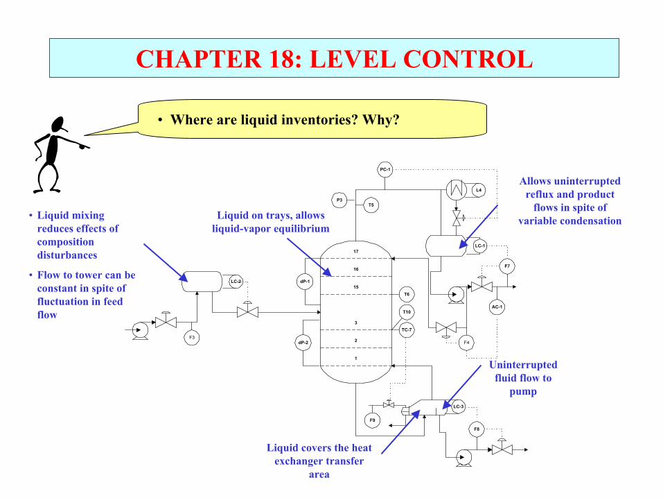
• Where are liquid inventories?
1
2
3
15
16
17LC-1
LC-3
LC-2 dP-1
dP-2
T5
T6
TC-7
AC-1
PC-1
P3
F3F4
F7
F8
F9
T10
L4
CHAPTER 18: LEVEL CONTROL
• Where are liquid inventories? Why?
1
2
3
15
16
17LC-1
LC-3
LC-2 dP-1
dP-2
T5
T6
TC-7
AC-1
PC-1
P3
F3F4
F7
F8
F9
T10
L4
Liquid on trays, allows liquid-vapor equilibrium
• Liquid mixing reduces effects of composition disturbances
• Flow to tower can be constant in spite of fluctuation in feed flow
Allows uninterrupted reflux and product
flows in spite of variable condensation
Uninterrupted fluid flow to
pump
Liquid covers the heat exchanger transfer
area

CHAPTER 18: LEVEL CONTROL
• How do inventories affect performance of theprocess containing the liquid?
Strongly Weakly Insignificant
• Volume of chemical reactors, volume has strong effect on conversion
• Fast material degradation (reduce residence time)
• Equilibrium stages, both phases must be present, but amount beyond minimum does not affect process
• Heat exchangers, must have contact with area
• Drums and tanks, no change to material properties
But these inventories have strong effects
on the other processes influenced by the flows from these inventories

CHAPTER 18: LEVEL CONTROL
• What are ++ and -- for having liquid inventories?
NEGATIVE ASPECTSPOSITIVE ASPECTS
Conclusion: ??

CHAPTER 18: LEVEL CONTROL• What are ++ and -- for having liquid inventories?
NEGATIVE ASPECTS
• Hazards - large inventory
• Product quality - degradation
• Space in plant
• Cost- Equipment costs- Material costs (inventory)
POSITIVE ASPECTS
• Provide liquid to pumps
• Mixing to reduce effects of stream property disturbances
• Inventory enables flow out constant as flow in varies
• Required - process principles, e.g.,- chemical reactors- heat exchangers
Conclusion: We use only the minimum liquid inventory needed to achieve the desired process performance.

CHAPTER 18: LEVEL CONTROL
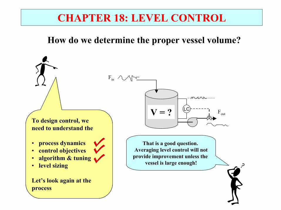
To design control, we need to understand the
• process dynamics• control objectives• algorithm & tuning • level sizing
Let’s determine thedynamics for each of thedesigns
CHAPTER 18: LEVEL CONTROL
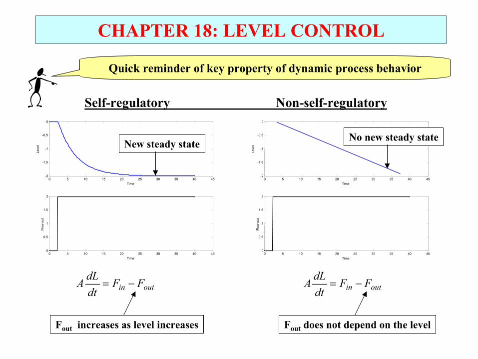
Self-regulatory Non-self-regulatory
0 5 10 15 20 25 30 35 40 45-2
-1.5
-1
-0.5
0
Time
Leve
l
0 5 10 15 20 25 30 35 40 450
0.5
1
1.5
2
Time
Flow
out
0 5 10 15 20 25 30 35 40 45-2
-1.5
-1
-0.5
0
Time
Leve
l0 5 10 15 20 25 30 35 40 45
0
0.5
1
1.5
2
TimeFl
ow o
ut
outin FFdtdLA −=
Fout does not depend on the level
outin FFdtdLA −=
Fout increases as level increases
Quick reminder of key property of dynamic process behavior
New steady state No new steady state

CHAPTER 18: LEVEL CONTROL
0≈dtdL
)( LKF
FFdtdLA
in
outin
−=
−=
21 PPKF
FFdtdLA
in
outin
−−=
−=
P1 = pump head + ρgL
21 PPKF
FFdtdLA
in
outin
−−=
−=
P1 = P3 + ρgL
≈ 0
0 5 10 15 20 25 30 35 40 45-2
-1.5
-1
-0.5
0
Time
Leve
l
0 5 10 15 20 25 30 35 40 450
0.5
1
1.5
2
Time
Flow
out
Non-Self-regulatory
0 5 10 15 20 25 30 35 40 45-2
-1.5
-1
-0.5
0
Time
Leve
l
0 5 10 15 20 25 30 35 40 450
0.5
1
1.5
2
Time
Flow
out
Self-regulatoryConstant
0 5 10 15 20 25 30 35 40 45-2
-1.5
-1
-0.5
0
Time
Leve
l
0 5 10 15 20 25 30 35 40 450
0.5
1
1.5
2
Time
Flow
out
Non-Self-regulatory≈ 0
Determine if each level is self-regulatory or not

To design control, we need to understand the
• process dynamics• control objectives• algorithm & tuning• level sizing
Let’s determine thecontrol objectivesfor level control
CHAPTER 18: LEVEL CONTROL
LC
Fin
Fout
What is important?
• The level
• The manipulated flow

CHAPTER 18: LEVEL CONTROL
LC
Fin
Fout
Control objectives
1. Since the level in unstable, we must control it!
2. We have two different categories of objectives
A. Tight level control for levels that strongly influence process performance (or are very small).
- Level near set point, aggressive flow adjustments
B. Averaging level control for drums and tanks, where smooth manipulation of flows will be beneficial to other units in the plant.
- Level far from set point (but doesn’t overflow), slower flow adjustments

To design control, we need to understand the
• process dynamics• control objectives• algorithm & tuning
Let’s determine thecontrol objectivesfor level control
To design control, we need to understand the
• process dynamics• control objectives• algorithm & tuning• level sizing
Let’s determine thealgorithm & tuningfor level control
CHAPTER 18: LEVEL CONTROL
LC
Fin
Fout
1. Is the control in the figure
a. feedback b. feedforward c. neitherd. both
2. What makes control difficult?

CHAPTER 18: LEVEL CONTROL
LC
Fin
Fout
1. Is the control in the figure
a. feedback b. feedforward c. neitherd. both
2. What makes control difficult?
Dead time makes feedback difficult, but we see that this process has negligible dead time!
Feedback: The flow out has a causal effect on the level.
Since this is feedback, let’s use the old standard, PI control(“D” isn’t needed).

LC
D = Fin
MV = Fout
CV = L
CHAPTER 18: LEVEL CONTROL
Controller Tuning
Can we use the standard PI tuning approach shown in
the schematic?
S-LOOP plots deviation variables (IAE = 608.1005)
0 5 10 15 20 25 30 35 40 45 5000.20.40.60.81
Time
Man
ipul
ated
Var
iabl
e 0 5 10 15 20 25 30 35 40 45 500
0.2
0.4
0.6
0.8
1DYNAMIC SIMULATION
Time
Con
trolle
d Va
riabl
e
Determine a model using the process reaction curve experiment.
Kc TI
Determine the initial tuning constants from a correlation.
0 20 40 60 80 100 1200
0.5
1
1.5S-LOOP plots deviation variables (IAE = 9.7189)
Time
Con
trolle
d Va
riabl
e
0 20 40 60 80 100 1200
0.5
1
1.5
Time
Man
ipul
ated
Var
iabl
e
Apply and fine tune as needed.
IdttLLT
tLLKtFtSP
ISPCout +
−+−= ∫0 '))'((1))(()(

LC
D = Fin
MV = Fout
CV = L
CHAPTER 18: LEVEL CONTROLS-LOOP plots deviation variables (IAE = 608.1005)
0 5 10 15 20 25 30 35 40 45 5000.20.40.60.81
Time
Man
ipul
ated
Var
iabl
e 0 5 10 15 20 25 30 35 40 45 500
0.2
0.4
0.6
0.8
1DYNAMIC SIMULATION
Time
Con
trolle
d Va
riabl
e Cannot determine a model using the process reaction curve experiment.
Kc TI
Cannot determine the initial tuning constants from Ciancone (or Ziegler-Nichols step) correlation.
0 5 10 15 20 25 30 35 40 45Time
Leve
l
0 5 10 15 20 25 30 35 40 45Time
Flow
out
Standard tuning charts are not applicable to a non-self-regulating level.
The level process is unstable. Without control, it never reaches a new steadystate

Gd(s)
GP(s)Gv(s)GC(s)
GS(s)
D(s)
CV(s)
CVm(s)
SP(s) E(s) MV(s)+
+
+
-LC
D = Fin
MV = Fout
CV = L
CHAPTER 18: LEVEL CONTROL
Let’s build a model of the process with the controller, i.e, the closed-loop system. We will ignore the fast sensor and valve dynamics.
Using block diagram algebra, we obtain
A = cross sectional area
)()(1)(
)()(
sGsGsG
sFsL
PC
D
in +=
With Gc(s) being either P-only of PI
For a non-self regulating level
AssGsG DP
1)()( ==

LC
D = Fin
MV = Fout
CV = L
CHAPTER 18: LEVEL CONTROL
We substitute the appropriate models for each process and controller to obtain the following transfer function models, which we can solve analytically for a step disturbance!
A = cross sectional area
AKT
andKAT
ss
KT
sFsL
CI
C
I
C
I
in
)(21
12)()(
22
−=
−=
++
−
=
ξτ
τξτ
Proportional-only control
Proportional-integral control
1
1
)()(
+
−
−=
sKA
KsFsL
C
C
in
+−=
+
−+−= ∫
sTKsG
IdttLLT
tLLKtF
ICC
tSP
ISPCout
11)(
'))'((1))(()(0
[ ]CC
SPCout
KsGItLLKtF
−=+−=
)()()(

CHAPTER 18: LEVEL CONTROL
• Stable, first order
• Never underdamped
• Non-zero s-s offset
• Stable, second order
• Underdamped when ξ < 1(We want overdamped!)
• Zero s-s offset
P-only PI
−
−∆=
−−cK
At
Cin eKFtL
/11)('
∆=
−−cK
Atin etAF
tL2/
)('
• Disturbance step response • Disturbance step response
[ ] ItLLKtF SPCout +−= )()( IdttLLT
tLLKtFtSP
ISPCout +
−+−= ∫0 '))'((1))(()(

CHAPTER 18: LEVEL CONTROL
P-only Tuning
Determine the expected maximum step disturbance size (∆Fmax) and calculate the Kc to give the maximum allowed change in the level (∆Lmax) .
LC Fout
∆Fmax
∆Lmax
Note, level doesnot return to itsset point.
When is this O.K?
Kc = - (∆Fmax)/ (∆Lmax)
∆Fout = ??
[ ] ItLLKtF SPCout +−= )()(

CHAPTER 18: LEVEL CONTROL
PI Tuning• Determine the expected maximum step disturbance size (∆Fmax) and
calculate the Kc and TI to give the maximum allowed change in the level (∆Lmax).
• Set tuning so that damping coefficient, ξ = 1.
LC Fout
∆Fmax
∆Lmax
Note, level returnsto its set point.
∆Fout = ??
Kc = - 0. 736 (∆Fmax)/ (∆Lmax) TI = 4 (ξ2) A/(-Kc)
∆Fout
IdttLLT
tLLKtFtSP
ISPCout +
−+−= ∫0 '))'((1))(()(

CHAPTER 18: LEVEL CONTROL
Let’s use these results for averaging and tight level control.
LC
Fin
Fout
P-only control: Kc = - (∆Fmax)/ (∆Lmax)
PI Control: Kc = - 0. 736 (∆Fmax)/ (∆Lmax) TI = 4 (ξ2) A/(-Kc)
Averaging level control, ∆Lmax ≈ 40% of maximum range
Tight level control, ∆Lmax ≈ 5% of maximum range
To design control, we need to understand the
• process dynamics• control objectives• algorithm & tuning
Let’s determine thecontrol objectivesfor level control
To design control, we need to understand the
• process dynamics• control objectives• algorithm & tuning • level sizing
Let’s look again at the process
CHAPTER 18: LEVEL CONTROL
How do we determine the proper vessel volume?
LC
Fin
FoutV = ?
That is a good question. Averaging level control will not
provide improvement unless the vessel is large enough!
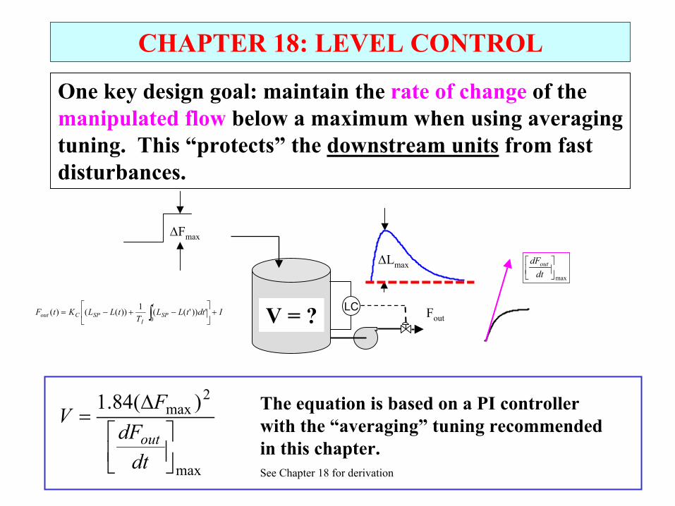
CHAPTER 18: LEVEL CONTROL
One key design goal: maintain the rate of change of the manipulated flow below a maximum when using averaging tuning. This “protects” the downstream units from fast disturbances.
LC Fout
∆Fmax
max
dtdFout
V = ?
max
2max )(84.1
∆=
dtdF
FV
out
The equation is based on a PI controller with the “averaging” tuning recommended in this chapter. See Chapter 18 for derivation
IdttLLT
tLLKtFtSP
ISPCout +
−+−= ∫0 '))'((1))(()(
∆Lmax

To design control, we need to understand the
• process dynamics• control objectives• algorithm & tuning • level sizing
CHAPTER 18: LEVEL CONTROL
LC
Fin
Fout
Now, we understand control of a single level!
How small can we make the levels?Do we have a guideline?

CHAPTER 18: LEVEL CONTROLProcess plants have many units in series. Inventory control behaves similar to a series of tanks. How should they be controlled?
F0
LC LC LC
F1 F2 F3
“Feed push” with levels adjusting flows out
F0
LC LC LC
F1 F2 F3
“Product pull” with levels adjusting flows in

CHAPTER 18: LEVEL CONTROL
For a series of levels, what is the importance of damping?
F0
LC LC LC
F1 F2 F3
Step change
We see that flow variation increases with number of levels in series
• P-only control is not oscillatory
• PI (ξ=1) experiences overshoot
• PI (ξ=0.5) experiences large oscillations
P-only
PI (ξ=1)
PI (ξ=0.5)
Best
Not acceptable

CHAPTER 18: LEVEL CONTROL WORKSHOP 1
We can have a liquid inventory that is not controlled, if the vessel is large enough. Let’s look at an example.
What is the minimum volume for the storage tank?
Plot the level vs. time.
L
Fin
FoutTime (days)
Flow
rate
The flow in involves batches of 24,000 m3
delivered over 12 hours, with a batch delivered every five days.
The flow out is the feed to the plant. It must be continuous and have a constant value.
1/2
5
CHAPTER 18: LEVEL CONTROL WORKSHOP 2
The principles we have learned for liquid level control apply to solid and gas inventories as well.
1. Think of an example in a process plant in which we need to have an inventory of a. (granular) solidsb. gas
2. Describe the storage equipment for each.
3. Select a sensor to measure the inventory for each
4. Determine whether the inventory is self-regulating or non-self-regulating.
5. Sketch the process with control.

CHAPTER 18: LEVEL CONTROL WORKSHOP 3
Discuss how you determine the proper liquid inventories for the following unit operations.
1. Liquid on the shell side of a shell and tube heat exchanger.
2. Liquid on a distillation tray
coolingmedium
TC10
FC1
Bypass andadjustable 3-way
mixing valve
1
2
3
15
16
17LC-1
LC-3
AC-1
PC-1
F4
F7
F8
AC-1

CHAPTER 18: LEVEL CONTROL WORKSHOP 3
3. Liquid in a flash drum
4. Liquid in a CSTR
Feed
Vaporproduct
LiquidproductProcess
fluidSteam
F1
F2 F3
T1 T2
T3
T5
T4
T6 P1
LC
A1
L. Key
Discuss how you determine the proper liquid inventories for the following unit operations.
L
F
T
A

CHAPTER 18: LEVEL CONTROL WORKSHOP 4
Calculate the level tuning for the situation described below. Determine the tuning for tight and for averaging control.
LC
Fin
Fout
V = 50 m3
A = 25 m2
F = 1.5 m3/min
∆Fmax = 1.0 m3/min
For each tuning, what would be the maximum rate of change of themanipulated flow for a step disturbance of ∆Fmax = 1.0 m3/min?

Lot’s of improvement, but we need some more study!• Read the textbook• Review the notes, especially learning goals and workshop• Try out the self-study suggestions• Naturally, we’ll have an assignment!
CHAPTER 18: LEVEL CONTROL
When I complete this chapter, I want to be able to do the following.
• Determine the location and volume of liquid inventories in a process
• Determine the dynamics of various level processes
• Tune level controllers for both typical control objectives

CHAPTER 18: LEARNING RESOURCES
• SITE PC-EDUCATION WEB - Instrumentation Notes - Level sensors!- Interactive Learning Module (Chapter 18)- Tutorials (Chapter 18)
• The Textbook, naturally, for many more examples.
• An entire book on inventory control? Sure, it is an important issue in corporate-wide production management.
Nahmias, S., Production and Operations Analysis, McGraw-Hill Irwin, New York, 2001.
CHAPTER 18: SUGGESTIONS FOR SELF-STUDY
1. Storing hazardous materials increases the risk in case of an accident. Search the WEB for information on the incident at Bhopal, India. Discuss the effect of the storage volume of methyl isocyanate on the number of deaths. A good place to start is
http://www.unu.edu/unupress/unupbooks/uu21le/uu21le00.htm#Contents
2. You are designing a reflux drum for a distillation tower that operates at 10 atm. How does the cost of a carbon steel, horizontal drum depend on the volume?
3. Discuss how you would monitor the performance of averaging level control. Based on plant data, define rules for fine tuning the controller.

CHAPTER 18: SUGGESTIONS FOR SELF-STUDY
4. Inventories are provided for all essential materials. Discuss how you would determine the proper storage inventory for some key materials, such as
a. Blood for transfusionsb. Food, e.g., grains and ricec. Water for a city
5. Describe the physical principles for sensors to measure the inventory of liquids, gases, and solids.