
CHAPTER 18-29 PLUMBING* - inspectapedia.com
181
Municipal Code of Chicago CHAPTER 18-29 PLUMBING* * Editor's note - Chapter 18-29, Water Service Charges and Plumbing Requirements, was added by Coun. J. 3-28-01, p. 55444, § 1. Coun. J. 11-21-17, p. 61913, § 8 amended the title of Chapter 18-29. Article 1. Administration 18-29-101 General. 18-29-101.1 Deliberately omitted. 18-29-101.2 Scope. 18-29-101.2.1 Department of Water Management requirements. 18-29-101.2.2 Department of Water requirements. 18-29-101.3 Intent 18-29-101.4 Deliberately omitted. 18-29-102 Applicability. 18-29-102.1 General. 18-29-102.2 Existing installations. 18-29-102.3 Maintenance. 18-29-102.4 Additions, alterations or repairs. 18-29-102.5 Change in occupancy. 18-29-102.6 Deliberately omitted. 18-29-102.7 Moved buildings. 18-29-102.8 Referenced codes and standards. 18-29-102.9 Requirements not covered by chapter. 18-29-103 Deliberately omitted. 18-29-104 Deliberately omitted. 18-29-105 Approval. 18-29-105.1 Modifications. 18-29-105.2 Alternative materials, methods and equipment. 18-29-105.3 Required testing. 18-29-105.3.1 Test methods. 18-29-105.3.2 Testing agency. 18-29-105.3.3 Test reports. 18-29-105.4 Alternative engineered design. 18-29-105.4.1 Design criteria. 18-29-105.4.2 Submittal.
Transcript of CHAPTER 18-29 PLUMBING* - inspectapedia.com

Municipal Code of Chicago
CHAPTER 18-29 PLUMBING*
* Editor's note - Chapter 18-29, Water Service Charges and Plumbing Requirements, was added by Coun. J. 3-28-01, p. 55444, § 1.Coun. J. 11-21-17, p. 61913, § 8 amended the title of Chapter 18-29.
Article 1. Administration
18-29-101 General.
18-29-101.1 Deliberately omitted.
18-29-101.2 Scope.
18-29-101.2.1 Department of Water Management requirements.
18-29-101.2.2 Department of Water requirements.
18-29-101.3 Intent
18-29-101.4 Deliberately omitted.
18-29-102 Applicability.
18-29-102.1 General.
18-29-102.2 Existing installations.
18-29-102.3 Maintenance.
18-29-102.4 Additions, alterations or repairs.
18-29-102.5 Change in occupancy.
18-29-102.6 Deliberately omitted.
18-29-102.7 Moved buildings.
18-29-102.8 Referenced codes and standards.
18-29-102.9 Requirements not covered by chapter.
18-29-103 Deliberately omitted.
18-29-104 Deliberately omitted.
18-29-105 Approval.
18-29-105.1 Modifications.
18-29-105.2 Alternative materials, methods and equipment.
18-29-105.3 Required testing.
18-29-105.3.1 Test methods.
18-29-105.3.2 Testing agency.
18-29-105.3.3 Test reports.
18-29-105.4 Alternative engineered design.
18-29-105.4.1 Design criteria.
18-29-105.4.2 Submittal.

18-29-105.4.3 Technical data.
18-29-105.4.4 Construction documents.
18-29-105.4.5 Design approval.
18-29-105.4.6 Inspection and testing.
18-29-105.5 Material and equipment reuse.
18-29-106 Permits.
18-29-106.1 Permits.
18-29-106.2 License required.
18-29-107 Fines.
Article 2. Definitions
18-29-201 General.
18-29-201.1 Scope.
18-29-201.2 Interchangeability.
18-29-201.3 Terms defined in other articles.
18-29-201.4 Terms not defined.
18-29-202 General definitions.
Article 3. General Regulations
18-29-301 General.
18-29-301.1 Scope.
18-29-301.1.1 New occupancy.
18-29-301.1.2 Age of building.
18-29-301.2 System installation.
18-29-301.3 Connections to drainage system.
18-29-301.4 Connections to water supply.
18-29-301.5 Pipe, tube and fitting sizes.
18-29-301.6 Prohibited locations.
18-29-302 Exclusion of Materials Detrimental to the Sewer System.
18-29-302.1 Detrimental or dangerous materials.
18-29-302.2 Industrial wastes.
18-29-303 Materials.
18-29-303.1 Identification.
18-29-303.2 Installation of materials.
18-29-303.3 Plastic pipe, fittings and components.
18-29-303.4 Labeling.
18-29-303.4.1 Testing.

18-29-303.4.2 Inspection and identification.
18-29-303.4.2.1 Independent.
18-29-303.4.2.2 Equipment.
18-29-303.4.2.3 Personnel.
18-29-304 Rodent-Proofing.
18-29-304.1 General.
18-29-304.2 Strainer plates.
18-29-304.3 Meter boxes.
18-29-304.4 Openings for pipes.
18-29-305 Protection of Pipes and Plumbing System Components.
18-29-305.1 Corrosion.
18-29-305.2 Breakage.
18-29-305.3 Stress and strain.
18-29-305.4 Sleeves.
18-29-305.5 Pipes through or under footings or foundation walls.
18-29-305.6 Freezing.
18-29-305.6.1 Sewer depth.
18-29-305.6.2 Water main depth.
18-29-305.7 Waterproofing of openings.
18-29-305.8 Protection against physical damage.
18-29-305.9 Protection of components of plumbing system.
18-29-306 Trenching, Excavation and Backfill.
18-29-306.1 Support of piping.
18-29-306.2 Trenching and bedding.
18-29-306.2.1 Overexcavation.
18-29-306.2.2 Rock removal.
18-29-306.2.3 Soft loadbearing materials.
18-29-306.3 Backfilling.
18-29-306.4 Tunneling.
18-29-306.5 Violations - Penalties.
18-29-307 Structural Safety.
18-29-307.1 General.
18-29-307.2 Cutting, notching or boring of holes.
18-29-307.3 Penetrations of floor-ceiling assemblies and fire-resistance-rated assemblies.
18-29-307.4 Trench location.
18-29-308 Piping Support.
18-29-308.1 General.
18-29-308.2 Deliberately omitted.
18-29-308.3 Materials.
18-29-308.4 Structural attachment.
18-29-308.5 Interval of support.
18-29-308.6 Sway bracing.
18-29-308.7 Anchorage.
18-29-308.7.1 Location.
18-29-308.8 Expansion joint fittings.
18-29-308.8.1 Vertical expansion.
18-29-308.9 Stacks.
18-29-308.10 Parallel water distribution systems.
18-29-309 Floodproofing.
18-29-309.1 General.
18-29-309.1.1 Base flood elevation.
18-29-309.2 Deliberately omitted.
18-29-310 Washroom and Toilet Room Requirements.
18-29-310.1 Ventilation.
18-29-310.2 Location of fixtures and piping.
18-29-310.3 Deliberately omitted.
18-29-310.4 Water closet compartment.
18-29-311 Toilet Facilities for Workers.
18-29-311.1 General; Workmen's temporary closets.
18-29-312 Tests and Inspections.
18-29-312.1 Required tests.
18-29-312.2 Drainage and vent water test.
18-29-312.3 Deliberately omitted.
18-29-312.4 Deliberately omitted.
18-29-312.5 Water supply system test.
18-29-312.6 Gravity sewer test.
18-29-312.7 Forced sewer test.
18-29-312.8 Storm drainage system test.
18-29-312.9 Cross connection control device inspections.
Article 4. Fixtures, Faucets and Fixture Fittings

18-29-401 General.
18-29-401.1 Scope.
18-29-401.2 Prohibited fixtures and connections.
18-29-401.3 Water conservation.
18-29-401.4 Separate toilet room.
18-29-401.5 WaterSense labeled fixtures and irrigation controllers.
18-29-402 Fixture Materials.
18-29-402.1 Quality of fixtures.
18-29-402.1.1 Used fixtures.
18-29-402.2 Materials for specialty fixtures.
18-29-402.3 Sheet copper.
18-29-402.4 Sheet lead.
18-29-402.5 Fixture strainer.
18-29-402.6 Fixture overflow.
18-29-403 Minimum Plumbing Facilities.
18-29-403.1 Minimum number of fixtures.
18-29-403.2 Separate facilities.
18-29-403.3 Number of occupants for both genders.
18-29-403.4 Location of employee toilet facilities in occupancies other than assembly ormercantile.
18-29-403.5 Toilet facilities in mercantile and assembly occupancies.
18-29-403.6 Customer facilities.
18-29-403.6.1 Pay facilities.
18-29-403.6.1.1 Included buildings.
18-29-403.7 Drinking fountains.
18-29-403.8 Multiple dwellings.
18-29-403.9 Kitchens.
18-29-404 Accessible Plumbing Facilities.
18-29-404.1 Where required.
18-29-405 Installation of Fixtures.
18-29-405.1 Water supply protection.
18-29-405.2 Access for cleaning.
18-29-405.2.1 Toilet room construction.
18-29-405.2.2 Day care centers.
18-29-405.3 Setting.

18-29-405.3.1 Water closets, lavatories and bidets.
18-29-405.3.2 Urinals.
18-29-405.4 Floor and wall drainage connections.
18-29-405.4.1 Floor flanges.
18-29-405.4.1.1 Hard lead floor flanges.
18-29-405.4.2 Securing floor outlet fixtures.
18-29-405.4.3 Securing wall-hung water closet bowls.
18-29-405.5 Water-tight joints.
18-29-405.6 Plumbing in mental health centers.
18-29-405.7 Design of overflows.
18-29-405.7.1 Connection of overflows.
18-29-405.8 Access to concealed connections.
18-29-406 Automatic Clothes Washers.
18-29-406.1 Approval.
18-29-406.2 Water connection.
18-29-406.3 Waste connection.
18-29-407 Bathtubs.
18-29-407.1 Approval.
18-29-407.2 Bathtub waste outlets.
18-29-407.3 Glazing.
18-29-408 Bidets.
18-29-408.1 Approval.
18-29-408.2 Water connection.
18-29-409 Dishwashing Machines.
18-29-409.1 Approval.
18-29-409.2 Water connection.
18-29-409.2.1 Water supply connection.
18-29-409.2.2 Hot water.
18-29-409.3 Waste connection.
18-29-409.3.1 Commercial dishwashers.
18-29-410 Drinking Fountains.
18-29-410.1 Approval.
18-29-410.2 Prohibited location.
18-29-411 Emergency Showers and Eyewash Stations.
18-29-411.1 Water connection.

18-29-411.2 Waste connection.
18-29-412 Floor Drains.
18-29-412.1 Approval.
18-29-412.2 Floor drain trap and strainer.
18-29-412.3 Size of floor drains.
18-29-412.4 Required location and construction.
18-29-412.4.1 Underground floor drains.
18-29-412.4.2 Sanitary waste drain.
18-29-412.4.3 Masonry or concrete floor.
18-29-412.4.4 Hospitals and nursing homes.
18-29-412.4.5 Public laundries and multiple- family dwellings.
18-29-412.4.6 Size.
18-29-412.4.7 Accessibility.
18-29-412.4.8 Provision for evaporation.
18-29-412.4.9 Floor drains in food establishments.
18-29-413 Food Waste Grinder Units.
18-29-413.1 Approval.
18-29-413.2 Domestic food waste grinder waste outlets.
18-29-413.3 Commercial food waste grinder waste outlets.
18-29-413.4 Water supply required.
18-29-414 Garbage Can Washers.
18-29-414.1 Water connection.
18-29-414.2 Waste connection.
18-29-415 Laundry Trays.
18-29-415.1 Approval.
18-29-415.2 Waste outlet.
18-29-416 Lavatories.
18-29-416.1 Approval.
18-29-416.2 Cultured marble lavatories.
18-29-416.3 Lavatory waste outlets.
18-29-417 Showers.
18-29-417.1 Approval.
18-29-417.2 Water supply riser.
18-29-417.3 Shower waste outlet.
18-29-417.4 Shower compartments.

18-29-417.4.1 Deliberately omitted.
18-29-417.4.2 Wall area.
18-29-417.4.3 Shower installation.
18-29-417.4.4 Water temperature safety.
18-29-417.4.5 Dimensions.
18-29-417.4.6 Materials.
18-29-417.4.7 Public or institution showers.
18-29-417.5 Shower floor or receptors.
18-29-417.5.1 Support.
18-29-417.5.2 Deliberately omitted.
18-29-417.6 Glazing.
18-29-418 Sinks.
18-29-418.1 Approval.
18-29-418.2 Sink waste outlets.
18-29-418.2.1 Facilities with no range oven.
18-29-419 Urinals.
18-29-419.1 Approval.
18-29-419.2 Substitution for water closets.
18-29-419.3 Urinals for public or employee toilet facilities.
18-29-419.4 Surrounding material.
18-29-420 Water Closets.
18-29-420.1 Approval.
18-29-420.2 Water closets for public or employee toilet facilities.
18-29-420.3 Water closet seats.
18-29-420.4 Water closet connections.
18-29-420.5 Deliberately omitted.
18-29-420.6 Chemical closets.
18-29-420.7 Temporary toilet facilities.
18-29-421 Whirlpool Bathtubs.
18-29-421.1 Approval.
18-29-421.2 Installation.
18-29-421.3 Drain.
18-29-421.4 Suction fittings.
18-29-422 Health Care Fixtures and Equipment.
18-29-422.1 Scope.

18-29-422.2 Deliberately omitted.
18-29-422.3 Deliberately omitted.
18-29-422.4 Deliberately omitted.
18-29-422.5 Deliberately omitted.
18-29-422.6 Deliberately omitted.
18-29-422.7 Deliberately omitted.
18-29-422.8 Deliberately omitted.
18-29-422.9 Sterilizer equipment requirements.
18-29-422.9.1 Sterilizer piping.
18-29-422.9.2 Steam supply.
18-29-422.9.3 Steam condensate return.
18-29-422.9.4 Condensers.
18-29-422.10 Special elevations.
18-29-423 Specialty Plumbing Fixtures.
18-29-423.1 Water connections.
18-29-423.2 Approval.
18-29-424 Faucets and Other Fixture Fittings.
18-29-424.1 Approval.
18-29-424.2 Hose spray.
18-29-424.3 Hand showers.
18-29-424.4 Shower valves.
18-29-425 Flushing Devices for Water Closets and Urinals.
18-29-425.1 Flushing devices required.
18-29-425.1.1 Separate for each fixture.
18-29-425.2 Flushometer valves and tanks.
18-29-425.3 Flush tanks.
18-29-425.3.1 Ball cocks.
18-29-425.3.2 Overflows in flush tanks.
18-29-425.3.3 Sheet copper.
18-29-425.3.4 Access required.
18-29-425.4 Flush pipes and fittings.
Article 5. Water Heaters
18-29-501 General.
18-29-501.1 Scope.
18-29-501.2 Deliberately omitted.

18-29-501.3 Drain valves.
18-29-501.4 Location for access.
18-29-501.5 Water heater labeling.
18-29-501.6 Tankless water heaters.
18-29-501.6.1 Coils.
18-29-501.7 Pressure marking of storage tanks.
18-29-501.8 Temperature controls.
18-29-501.8.1 Instantaneous water heaters.
18-29-501.9 Heat exchangers.
18-29-502 Installation.
18-29-502.1 General.
18-29-502.2 Water heaters installed in non- private garages.
18-29-502.3 Rooms used as a plenum.
18-29-502.4 Prohibited location.
18-29-502.5 Water heaters installed in closets accessed through sleeping rooms or bathrooms.
18-29-502.6 Water heaters installed in attics, basements or other areas.
18-29-503 Connections.
18-29-503.1 Cold water line valve.
18-29-503.1.1 Shutoff valves.
18-29-503.2 Deliberately omitted.
18-29-504 Safety Devices.
18-29-504.1 Antisiphon devices.
18-29-504.2 Vacuum relief valve.
18-29-504.3 Energy cutoff device.
18-29-504.4 Shutdown.
18-29-504.5 Relief valve.
18-29-504.5.1 Installation.
18-29-504.6 Relief valve approval.
18-29-504.7 Relief outlet waste.
18-29-504.7.1 Discharge.
18-29-504.7.2 Location.
18-29-504.7.3 Materials.
18-29-504.8 Required pan.
18-29-504.8.1 Pan size and drain.
18-29-504.8.2 Pan drain termination.

18-29-505 Insulation.
18-29-505.1 Unfired vessel insulation.
Article 6. Water Supply and Distribution
18-29-601 General.
18-29-601.1 Scope.
18-29-601.2 Inspections and notices.
18-29-601.3 Access for inspections.
18-29-601.4 Solar energy utilization.
18-29-602 Water Required.
18-29-602.1 General.
18-29-602.1.1 Obligations of water consumers.
18-29-602.2 Potable water required.
18-29-602.3 Deliberately omitted.
18-29-602.4 Reserve water supply.
18-29-602.4.1 Installation of line valves or taps.
18-29-602.4.2 Dual meter settings.
18-29-603 Water Service.
18-29-603.1 Size of water service pipe.
18-29-603.1.1 Size and meter spreader connection.
18-29-603.1.2 Sizing of connections.
18-29-603.1.3 Permits to install water supply in buildings.
18-29-603.2 Separation of water service and building sewer/drain.
18-29-603.2.1 Water supply systems installed near a sewer structure.
18-29-603.2.2 Reserved.
18-29-603.2.3 Backfill.
18-29-603.3 Metered service.
18-29-603.3.1 Authority.
18-29-603.3.2 Connection of nonmetered to metered service.
18-29-603.3.3 Licensed and bonded contractor.
18-29-603.3.4 Location.
18-29-603.3.5 Construction of meter vaults.
18-29-603.3.6 Installation of taps.
18-29-603.3.7 Plans accompany permit application.
18-29-603.3.8 Notification of wrecking buildings for terminating water service.
18-29-604 Design of Building Water Distribution System.

18-29-604.1 General.
18-29-604.2 System interconnection.
18-29-604.3 Water distribution system design criteria.
18-29-604.4 Maximum flow and water consumption.
18-29-604.4.1 Deliberately omitted.
18-29-604.4.2 Water closets.
18-29-604.5 Size of fixture supply.
18-29-604.5.1 Minimum size.
18-29-604.6 Variable street pressures.
18-29-604.7 Inadequate water pressure.
18-29-604.8 Water pressure reducing valve or regulator.
18-29-604.8.1 Valve design.
18-29-604.8.2 Repair and removal.
18-29-604.9 Deliberately omitted.
18-29-604.10 Size of water supply pipes.
18-29-604.10.1 Minimum sizes of branch distributing pipes for fixtures and appliances.
18-29-604.10.1.1 Demand load.
18-29-604.10.1.2 Size of piping.
18-29-604.10.1.3 Available pressure.
18-29-604.10.2 Procedures for calculating sizing.
18-29-604.11 Air chambers required.
18-29-604.11.1 Size of air chamber.
18-29-605 Materials, Joints and Connections.
18-29-605.1 Water compatibility.
18-29-605.2 Soil and ground water.
18-29-605.3 Lead content of water supply pipe and fittings.
18-29-605.4 Water service pipe.
18-29-605.4.1 Materials for supply pipes and fittings.
18-29-605.5 Water distribution pipe.
18-29-605.6 Fittings.
18-29-605.7 Valves.
18-29-605.8 Manufactured pipe nipples.
18-29-605.9 Prohibited joints and connections.
18-29-605.10 Deliberately omitted.
18-29-605.11 Deliberately omitted.

18-29-605.12 Brass.
18-29-605.12.1 Brazed joints.
18-29-605.12.2 Mechanical joints.
18-29-605.12.3 Threaded joints.
18-29-605.12.4 Welded joints.
18-29-605.13 Gray iron and ductile iron joints.
18-29-605.14 Copper pipe.
18-29-605.14.1 Deliberately omitted.
18-29-605.14.2 Deliberately omitted.
18-29-605.14.3 Soldered joints.
18-29-605.15 Copper tubing.
18-29-605.15.1 Brazed joints.
18-29-605.15.2 Flared joints.
18-29-605.15.3 Mechanical joints.
18-29-605.15.4 Soldered joints.
18-29-605.16 CPVC plastic.
18-29-605.16.1 Mechanical joints.
18-29-605.16.2 Solvent cementing.
18-29-605.16.3 Threaded joints.
18-29-605.17 Steel.
18-29-605.17.1 Threaded joints.
18-29-605.17.2 Mechanical joints.
18-29-605.18 Deliberately omitted.
18-29-605.19 Deliberately omitted.
18-29-605.20 Deliberately omitted.
18-29-605.21 Joints between different materials.
18-29-605.21.1 Copper or copper-alloy tubing to galvanized steel pipe.
18-29-605.22 Protection for pipes and fixtures.
18-29-605.23 Hydrants and non-freeze hydrants protection.
18-29-605.24 Water supply pipe protection.
18-29-605.25 Refrigerant condensers.
18-29-605.26 Dead-ends prohibited.
18-29-605.27 Air conditioning and refrigeration systems.
18-29-605.28 Permissible exceptions.
18-29-606 Installation of the Building Water Distribution System.

18-29-606.1 Location of full-open valves.
18-29-606.2 Location of shutoff valves.
18-29-606.3 Access to valves.
18-29-606.4 Valve identification.
18-29-606.5 Water pressure booster systems.
18-29-606.5.1 Hydropneumatic system, booster pump system, gravity tank.
18-29-606.5.1.1 Requirements.
18-29-606.5.1.1.1 Pressure relief valve.
18-29-606.5.1.1.2 Compression tank.
18-29-606.5.1.1.3 Sludge drain pipe.
18-29-606.5.1.2 Booster pump system.
18-29-606.5.1.2.1 Gravity tanks.
18-29-606.5.1.2.2 Total pressure.
18-29-606.5.1.2.3 Low pressure cutoff.
18-29-606.5.2 Surge tank for pumps.
18-29-606.5.3 Check valves required.
18-29-606.5.3.1 Approval required.
18-29-606.5.4 Equipment required for tanks receiving city water.
18-29-606.5.4.1 Sludge drain pipe.
18-29-606.5.4.2 Size.
18-29-606.5.4.3 Covers and support.
18-29-606.5.5 Recycling system for vehicle wash installations.
18-29-606.5.6 Potable water inlet control and location.
18-29-606.5.7 Tank drain pipes.
18-29-606.5.8 Prohibited location of potable supply tanks.
18-29-606.5.9 Pressure relief valve requirements.
18-29-606.5.10 Pressure relief valves for hydropneumatic tanks.
18-29-606.6 Test of distribution pipes.
18-29-607 Hot Water Supply System.
18-29-607.1 Where required.
18-29-607.1.1 Water temperature.
18-29-607.1.2 Shower compartments and shower- bath combinations.
18-29-607.1.2.1 Mixed water temperature.
18-29-607.2 Heated plumbing circulating system.
18-29-607.2.1 Return piping.

18-29-607.2.1A Piping insulation.
18-29-607.2.2 Pump operation.
18-29-607.3 Thermal expansion control.
18-29-607.3.1 Pressure reducing valve.
18-29-607.3.2 Backflow prevention device or check valve.
18-29-607.4 Hot water supply to fixtures.
18-29-607.5 Expansion joints.
18-29-607.6 Prohibited connections.
18-29-608 Protection of Potable Water Supply.
18-29-608.1 General.
18-29-608.2 Plumbing fixtures.
18-29-608.3 Water supply pipes.
18-29-608.3.1 Special equipment, water supply protection.
18-29-608.4 Deliberately omitted.
18-29-608.5 Secondary water.
18-29-608.6 Prohibited use of secondary water.
18-29-608.6.1 Private water supplies.
18-29-608.7 Stop-and-waste valves prohibited.
18-29-608.8 Identification of potable and nonpotable water.
18-29-608.9 Re-utilization prohibited.
18-29-608.10 Reuse of piping.
18-29-608.11 Painting of water tanks.
18-29-608.12 Pumps and other appliances.
18-29-608.13 Backflow protection.
18-29-608.13.1 Air gap.
18-29-608.13.2 Reduced pressure principle backflow preventers.
18-29-608.13.3 Backflow preventer with intermediate atmospheric vent.
18-29-608.13.4 Barometric loop.
18-29-608.13.5 Atmospheric-type vacuum breakers.
18-29-608.13.6 Double check-valve assemblies.
18-29-608.14 Location of backflow preventers.
18-29-608.15 Protection of potable water outlets.
18-29-608.16 Connections to the potable water system.
18-29-608.16.1 Beverage carbonator.
18-29-608.16.1.1 Backflow preventer.

18-29-608.16.2 High-pressure steam boilers.
18-29-608.16.3 Connections to automatic fire sprinkler systems and standpipe systems.
18-29-608.16.4 Fire protection equipment, risers, standpipes, tanks to be drained and flushed.
18-29-608.16.5 Fire-extinguishing equipment cross- connection.
18-29-608.16.5.1 Prohibitions.
18-29-608.16.6 Chemical or petroleum pressure vessels.
18-29-608.16.6.1 Chemical or petroleum pressure vessels.
18-29-608.16.6.2 Water flushing or cooling.
18-29-608.16.6.3 Chemical, contaminated water, or sewage lines or vessels.
18-29-608.16.7 Deliberately omitted.
18-29-608.16.8 Portable cleaning equipment.
18-29-608.16.9 Dental pump equipment.
18-29-608.17 Private water supplies.
18-29-608.17.1 Well locations.
18-29-608.17.1.1 Distances.
18-29-608.17.1.2 Direct connections.
18-29-609 Health Care Plumbing.
18-29-609.1 General.
18-29-609.1.1 Where required.
18-29-609.2 Water service.
18-29-609.3 Hot water.
18-29-609.4 Vacuum breaker installation.
18-29-609.5 Prohibited water closet and clinical sink supply.
18-29-609.6 Clinical, hydrotherapeutic and radiological equipment.
18-29-609.7 Condensate drain trap seal.
18-29-609.8 Valve leakage diverter.
18-29-610 Disinfection of Potable Water System.
18-29-610.1 Scope.
18-29-611 Water Treatment Units.
18-29-611.1 Design.
18-29-611.2 Reverse osmosis systems.
Article 7. Sanitary Drainage
18-29-701 General.
18-29-701.1 Scope.
18-29-701.2 Sewer required.

18-29-701.3 Separate building sewer connection.
18-29-701.4 Sewage treatment.
18-29-701.5 Damage to drainage system or public sewer.
18-29-701.6 Tests.
18-29-701.7 Connections.
18-29-701.8 Notification of wrecking buildings and sealing or abandoning sewer facilities.
18-29-702 Materials.
18-29-702.1 Above-ground sanitary drainage and vent pipe.
18-29-702.2 Underground building drainage and vent pipe.
18-29-702.3 Building sewer pipe.
18-29-702.4 Fittings.
18-29-702.5 Chemical waste system.
18-29-702.5.1 Glass pipe.
18-29-702.5.1.1 Padding.
18-29-702.5.1.2 Thickness.
18-29-702.5.1.3 Buried pipe.
18-29-702.6 Safe pan material and construction.
18-29-702.6.1 Material.
18-29-702.6.2 Construction.
18-29-703 Building Sewer.
18-29-703.1 Building sewers, building drains or drainage systems installed near the water pipesand water supply system.
18-29-703.2 Drainage pipe in filled ground.
18-29-703.3 Sanitary and storm sewers.
18-29-703.3.1 Combined sewers.
18-29-703.4 Existing building sewers and drains.
18-29-703.4.1 Inspection of existing underground building sewers for drain and reuse.
18-29-704 Drainage Piping and Installation.
18-29-704.1 Slope of horizontal drainage piping.
18-29-704.2 Change in size.
18-29-704.3 Connections to offsets and bases of stacks.
18-29-704.4 Future fixtures.
18-29-704.5 Dead ends.
18-29-704.5.1 Freezing.
18-29-704.5.2 Deliberately omitted.

18-29-705 Joints.
18-29-705.1 General.
18-29-705.2 Deliberately omitted.
18-29-705.3 Deliberately omitted.
18-29-705.4 Brass.
18-29-705.4.1 Brazed joints.
18-29-705.4.2 Mechanical joints.
18-29-705.4.3 Threaded joints.
18-29-705.4.4 Welded joints.
18-29-705.5 Cast iron.
18-29-705.5.1 Caulked joints.
18-29-705.5.2 Compression gasket joints.
18-29-705.5.3 Mechanical joint coupling.
18-29-705.6 Concrete joints.
18-29-705.7 Copper pipe.
18-29-705.7.1 Brazed joints.
18-29-705.7.2 Mechanical joints.
18-29-705.7.3 Soldered joints.
18-29-705.7.4 Threaded joints.
18-29-705.7.5 Welded joints.
18-29-705.8 Copper tubing.
18-29-705.8.1 Brazed joints.
18-29-705.8.2 Mechanical joints.
18-29-705.8.3 Soldered joints.
18-29-705.9 Borosilicate glass joints.
18-29-705.9.1 Caulked joints.
18-29-705.10 Steel.
18-29-705.10.1 Threaded joints.
18-29-705.10.2 Mechanical joints.
18-29-705.11 Deliberately omitted.
18-29-705.12 PVC plastic.
18-29-705.12.1 Mechanical joints.
18-29-705.12.2 Solvent cementing.
18-29-705.12.3 Threaded joints.
18-29-705.13 Vitrified clay.

18-29-705.14 Joints between different materials.
18-29-705.14.1 Copper or copper-alloy tubing to cast-iron hub pipe.
18-29-705.14.2 Copper or copper-alloy tubing to galvanized steel pipe.
18-29-705.14.3 Cast-iron pipe to galvanized steel or brass pipe.
18-29-705.14.4 Plastic pipe or tubing to other piping material.
18-29-705.14.5 Deliberately omitted.
18-29-705.14.6 Borosilicate glass to other materials.
18-29-705.15 Drainage slip joints.
18-29-705.16 Caulking ferrules.
18-29-705.17 Deliberately omitted.
18-29-706 Connections Between Drainage Piping And Fixtures.
18-29-706.1 Connections and changes in direction.
18-29-706.2 Obstructions.
18-29-706.3 Installation of fittings.
18-29-707 Prohibited Joints and Connections.
18-29-707.1 Prohibited joints.
18-29-708 Cleanouts.
18-29-708.1 Scope.
18-29-708.2 Cleanout plugs.
18-29-708.3 Where required.
18-29-708.3.1 Horizontal drains within buildings.
18-29-708.3.2 Building sewers.
18-29-708.3.3 Changes of direction.
18-29-708.3.4 Base of stack.
18-29-708.3.5 Building drain and building sewer junction.
18-29-708.3.6 Manholes.
18-29-708.4 Concealed piping.
18-29-708.5 Opening direction.
18-29-708.6 Prohibited installation.
18-29-708.7 Minimum size.
18-29-708.8 Pipes 8 inches and larger.
18-29-708.9 Clearances.
18-29-708.10 Access.
18-29-709 Fixture Units.
18-29-709.1 Values for fixtures.

18-29-709.2 Fixtures not listed in Table 18-29-709.1.
18-29-709.3 Values for continuous flow.
18-29-709.4 Deliberately omitted.
18-29-709.5 Values for indirect waste receptor.
18-29-710 Drainage System Sizing.
18-29-710.1 Maximum fixture unit load.
18-29-710.1.1 Maximum fixture units.
18-29-710.1.2 Minimum size.
18-29-710.1.3 Horizontal stack offsets.
18-29-710.1.4 Vertical stack offsets.
18-29-710.2 Future fixtures.
18-29-710.3 Underground drainage piping.
18-29-711 Offsets in Drainage Piping in Buildings of Five Stories or More.
18-29-711.1 Horizontal branch connections above or below vertical stack offsets.
18-29-711.1.1 Omission of vents for vertical stack offsets.
18-29-711.2 Horizontal branch connections to horizontal stack offsets.
18-29-711.3 Horizontal stack offsets.
18-29-711.3.1 Omission of vents for horizontal stack offsets.
18-29-711.3.2 Suds pressure zones.
18-29-711.3.2.1 Height.
18-29-711.3.2.2 Upstream.
18-29-711.3.2.3 Downstream.
18-29-711.4 Offsets below lowest branch.
18-29-712 Sumps and Ejectors.
18-29-712.1 Building drains below sewer.
18-29-712.2 Check and gate valve required.
18-29-712.3 Sump design.
18-29-712.3.1 Sump pump.
18-29-712.3.2 Sump pit.
18-29-712.3.3 Discharge piping.
18-29-712.3.4 Maximum effluent level.
18-29-712.3.5 Ejector connection to the drainage system.
18-29-712.4 Sewage pumps and sewage ejectors.
18-29-712.4.1 Capacity.
18-29-712.4.2 Duplex equipment required.

18-29-713 Health Care Plumbing.
18-29-713.1 Scope.
18-29-713.2 Bedpan washers and clinical sinks.
18-29-713.3 Indirect waste.
18-29-713.4 Vacuum system station.
18-29-713.5 Bottle system.
18-29-713.6 Central disposal system equipment.
18-29-713.7 Central vacuum or disposal systems.
18-29-713.7.1 Piping.
18-29-713.7.2 Velocity.
18-29-713.8 Vent connections prohibited.
18-29-713.9 Local vents and stacks for bedpan washers.
18-29-713.9.1 Multiple installations.
18-29-713.9.2 Trap required.
18-29-713.9.3 Trap seal maintenance.
18-29-713.10 Sterilizer vents and stacks.
18-29-713.10.1 Drainage.
18-29-713.11 Sterilizer vent stack sizes.
18-29-713.11.1 Bedpan steamers.
18-29-713.11.2 Boiling-type sterilizers.
18-29-713.11.3 Pressure sterilizers.
18-29-713.11.4 Pressure instrument washer sterilizer sizes.
18-29-714 Deliberately omitted.
18-29-715 Backwater Valves.
18-29-715.1 Sewage backflow.
18-29-715.2 Fixture branches.
18-29-715.3 Material.
18-29-715.4 Seal.
18-29-715.5 Diameter.
18-29-715.6 Location.
18-29-716 Flood Control.
18-29-716.1 Flood control devices.
18-29-716.2 Flood control systems.
Article 8. Indirect/Special Waste
18-29-801 General.

18-29-801.1 Scope.
18-29-801.2 Protection.
18-29-802 Indirect Wastes.
18-29-802.1 Where required.
18-29-802.1.1 Deliberately omitted.
18-29-802.1.2 Deliberately omitted.
18-29-802.1.3 Potable clear-water waste.
18-29-802.1.4 Nonpotable clear-water waste.
18-29-802.1.5 Waste piping.
18-29-802.1.6 Dishwashing machine.
18-29-802.1.7 Sinks.
18-29-802.2 Deliberately omitted.
18-29-802.3 Waste receptors.
18-29-802.3.1 Open hub waste receptors.
18-29-802.4 Standpipes.
18-29-803 Special Wastes.
18-29-803.1 Deliberately omitted.
18-29-803.2 Neutralizing device required for corrosive wastes.
18-29-803.3 System design.
18-29-803.4 Volatile wastes.
18-29-804 Materials, Joints and Connections.
18-29-804.1 General.
18-29-804.2 Acid waste piping material.
18-29-805 Waste Water Control.
18-29-805.1 Preliminary treatment.
18-29-805.1.1 Approval.
18-29-805.2 Prohibited wastes.
18-29-805.2.1 Maximum concentration.
18-29-805.2.2 Types of discharge.
18-29-805.3 Discharges of clean waters.
18-29-805.4 Manholes.
18-29-805.4.1 Use and permit.
18-29-805.5 Gauging and sampling.
18-29-805.5.1 Legal or financial obligation.
18-29-805.6 Sampling methods.

18-29-805.7 Analyses.
18-29-805.7.1 Preliminary treatment.
18-29-805.7.2 Written approval.
Article 9. Vents
18-29-901 General.
18-29-901.1 Scope.
18-29-901.2 Trap seal protection.
18-29-901.2.1 Venting required.
18-29-901.3 Chemical waste vent system.
18-29-901.4 Use limitations.
18-29-901.5 Tests.
18-29-901.6 Protection from freezing.
18-29-902 Materials.
18-29-902.1 Vents.
18-29-902.2 Sheet copper.
18-29-902.3 Sheet lead.
18-29-903 Vent Stacks and Stack Vents.
18-29-903.1 Main vent required.
18-29-903.2 Vent stack required.
18-29-903.3 Vent termination.
18-29-903.4 Vent connection at base.
18-29-903.5 Vent headers.
18-29-904 Vent Terminals.
18-29-904.1 Roof extension.
18-29-904.2 Frost closure.
18-29-904.3 Flashings.
18-29-904.4 Prohibited use.
18-29-904.5 Location of vent terminal.
18-29-904.6 Extension through the wall.
18-29-905 Vent Connections and Grades.
18-29-905.1 Connection.
18-29-905.2 Grade.
18-29-905.3 Vent connection to drainage system.
18-29-905.4 Vertical rise of vent.
18-29-905.5 Height above fixtures.

18-29-905.6 Side inlet.
18-29-905.7 Vent for future fixtures.
18-29-906 Fixture Vents.
18-29-906.1 Distance of trap from vent.
18-29-906.2 Venting of fixture drains.
18-29-906.3 Crown vent.
18-29-907 Individual Vent.
18-29-907.1 Individual vent permitted.
18-29-908 Common Vent.
18-29-908.1 Individual vent as common vent.
18-29-908.2 Connection at the same level.
18-29-908.3 Connection of different levels.
18-29-909 Deliberately omitted.
18-29-910 Deliberately omitted.
18-29-911 Deliberately omitted.
18-29-912 Combination Drain and Vent System.
18-29-912.1 Type of fixtures.
18-29-912.2 Waste piping and trap.
18-29-912.2.1 Branches.
18-29-912.2.2 Sinks, lavatories, and other fixtures.
18-29-912.2.3 Long mains.
18-29-912.2.4 Floor drains.
18-29-912.3 Size.
18-29-913 Island Fixture Venting.
18-29-913.1 Limitation.
18-29-913.2 Vent connection.
18-29-913.3 Vent installation below the fixture flood level rim.
18-29-914 Relief Vents - Stacks of More Than 10 Branch Intervals.
18-29-914.1 Where required.
18-29-914.2 Size and connection.
18-29-915 Vents for Stack Offsets.
18-29-915.1 Vent for horizontal offset of drainage stack.
18-29-915.2 Upper section.
18-29-915.3 Lower section.
18-29-916 Vent Pipe Sizing.

18-29-916.1 Size of stack vents and vent stacks.
18-29-916.2 Other vents.
18-29-916.3 Required sizes of vents.
18-29-916.4 Multiple branch vents.
18-29-916.4.1 Multiple branch vents exceeding 40 feet.
18-29-916.5 Sump vents.
18-29-916.5.1 Sewage pumps and sewage ejectors other than pneumatic.
18-29-916.5.2 Pneumatic sewage ejectors.
18-29-917 Vents Not Required.
18-29-917.1 Not required.
18-29-918 Deliberately omitted.
Article 10. Traps, Separators and Interceptors
18-29-1001 General.
18-29-1001.1 Scope.
18-29-1002 Trap Requirements.
18-29-1002.1 Fixture traps.
18-29-1002.1.1 Open plumbing.
18-29-1002.1.2 Traps underground.
18-29-1002.1.3 Animal facilities and barn drainage.
18-29-1002.1.4 Basement floor drains.
18-29-1002.1.5 Backwater valves.
18-29-1002.2 Design of traps.
18-29-1002.3 Prohibited traps.
18-29-1002.4 Trap seals.
18-29-1002.5 Size of fixture traps.
18-29-1002.6 Deliberately omitted.
18-29-1002.7 Trap setting and protection.
18-29-1002.8 Recess for trap connection.
18-29-1002.9 Acid-resisting traps.
18-29-1002.10 Plumbing in mental health centers.
18-29-1003 Interceptors and Separators.
18-29-1003.1 Interceptors required.
18-29-1003.1.1 Interceptors not required.
18-29-1003.2 Size, type and location to be approved.
18-29-1003.3 Grease interceptor or catch basin.

18-29-1003.3.1 Where required.
18-29-1003.3.2 Grease, fats and oils.
18-29-1003.3.3 Grease interceptors and discharge.
18-29-1003.3.4 Construction materials.
18-29-1003.3.5 Types.
18-29-1003.3.6 Grease trap capacity.
18-29-1003.3.7 Rate of flow controls.
18-29-1003.3.8 Efficiency of interceptors.
18-29-1003.4 Grease catch basins outside.
18-29-1003.4.1 Basin cover.
18-29-1003.5 Deliberately omitted.
18-29-1003.6 Volatile waste separator.
18-29-1003.6.1 Garages.
18-29-1003.7 Separation of liquids.
18-29-1003.7.1 General design requirements.
18-29-1003.7.2 Garage and service stations.
18-29-1003.8 Sand interceptors in commercial establishments.
18-29-1003.9 Laundries.
18-29-1003.10 Bottling establishments.
18-29-1003.11 Slaughterhouses.
18-29-1003.12 Venting of interceptors and separators.
18-29-1003.13 Access and maintenance of interceptors and separators.
18-29-1004 Materials, Joints and Connections.
18-29-1004.1 General.
Article 11. Storm Drainage
18-29-1101 General.
18-29-1101.1 Scope.
18-29-1101.2 Where required.
18-29-1101.2.1 Roof drainage and downspouts.
18-29-1101.2.2 Drainage of areas and yards.
18-29-1101.2.3 Storm runoff.
18-29-1101.3 Prohibited drainage.
18-29-1101.4 Tests.
18-29-1101.5 Continuous flow.
18-29-1101.6 Fittings and connections.

18-29-1101.7 Roof design.
18-29-1101.8 Cleanouts required.
18-29-1101.9 Backwater valves.
18-29-1102 Materials.
18-29-1102.1 General.
18-29-1102.2 Inside storm drainage conductors.
18-29-1102.3 Underground building storm drain pipe.
18-29-1102.4 Building storm sewer standards.
18-29-1102.5 Subsoil drain pipe.
18-29-1102.6 Roof drains.
18-29-1102.7 Fittings.
18-29-1103 Traps.
18-29-1103.1 Main trap.
18-29-1103.2 Material.
18-29-1103.3 Size.
18-29-1103.4 Cleanout.
18-29-1104 Conductors and Connections.
18-29-1104.1 Prohibited use.
18-29-1104.1.1 District sewer lines.
18-29-1104.2 Combining storm with sanitary drainage.
18-29-1104.2.1 Separate sewer systems.
18-29-1104.3 Floor drains.
18-29-1105 Roof Drains.
18-29-1105.1 Strainers.
18-29-1105.2 Flat decks.
18-29-1105.3 Roof drain flashing.
18-29-1105.4 Maximum area.
18-29-1106 Size of Conductors, Leaders and Storm Drains.
18-29-1106.1 General.
18-29-1106.2 Vertical conductors and leaders.
18-29-1106.3 Building storm drains and sewers.
18-29-1106.4 Vertical walls.
18-29-1106.5 Parapet wall scupper location.
18-29-1106.6 Size of roof gutters.
18-29-1107 Fines.

18-29-1108 Combined Sanitary and Storm System.
18-29-1108.1 Size of combined drains and sewers.
18-29-1109 Values for Continuous Flow.
18-29-1109.1 Equivalent roof area.
18-29-1110 Controlled Flow Roof Drain Systems.
18-29-1110.1 General.
18-29-1110.1.1 Design.
18-29-1110.2 Control devices.
18-29-1110.3 Installation.
18-29-1110.4 Minimum number of roof drains.
18-29-1111 Sumps.
18-29-1111.1 Subsoil drains.
18-29-1111.2 Building subdrains.
18-29-1111.3 Pumping system.
18-29-1111.3.1 Pump capacity and head.
18-29-1111.3.2 Construction.
18-29-1111.3.3 Electrical.
18-29-1111.3.4 Piping.
Article 12. Swimming Pools
18-29-1200 General.
18-29-1200.1 Scope.
18-29-1200.2 Definition - nonprivate swimming pool.
18-29-1200.3 Definition - private swimming pool.
Part I
18-29-1201 Nonprivate Swimming Pools Generally.
18-29-1201.1 Scope.
18-29-1201.2 Prohibited locations.
18-29-1201.3 Permit requirements.
18-29-1202 Construction.
18-29-1202.1 Nonprivate swimming pools.
18-29-1202.2 Recirculation inlets.
18-29-1202.3 Outlets.
18-29-1202.4 Hose connections.
18-29-1202.5 Overflow gutters.
18-29-1202.6 Equipment for removal of sediment.

18-29-1202.7 Recirculation system.
18-29-1202.7.1 Turnover of pool contents.
18-29-1202.8 Equipment required.
18-29-1202.9 Strainer required.
18-29-1202.10 Disinfection equipment.
18-29-1202.11 Chemical equipment.
18-29-1202.11.1 Coagulant solutions.
18-29-1202.12 Filtration equipment.
18-29-1202.12.1 Filter area.
18-29-1202.12.2 Underdrain system size.
18-29-1202.12.3 Filter sand depth.
18-29-1202.12.4 Loss-of-head gauges.
18-29-1202.12.5 Proper design.
18-29-1202.12.6 Pressure sand filter system provisions.
18-29-1202.12.7 Filter media other than sand.
18-29-1202.12.8 Sight glass.
18-29-1202.12.9 Filter piping arrangement.
18-29-1202.13 Make-up water.
18-29-1202.14 Sewage or waste water.
18-29-1202.15 Cleanouts.
18-29-1202.16 Accessibility.
18-29-1202.17 Hydrogen-ion concentration.
18-29-1202.18 Disinfectant residuals.
18-29-1203 Additional Facilities Required.
18-29-1203.1 Equipment room location and drainage.
18-29-1203.2 Dressing room drainage.
18-29-1203.3 Shower facilities.
18-29-1203.4 Toilet facilities.
18-29-1203.4.1 Inside dry.
18-29-1203.4.2 Inside wet.
18-29-1203.4.3 Fixtures.
18-29-1203.4.3.1 Smaller pools.
18-29-1203.4.3.2 Larger pools.
18-29-1203.4.4 Deliberately omitted.
18-29-1203.4.5 Backsiphonage.

18-29-1203.4.6 Cleaning.
18-29-1203.4.7 Splashing.
18-29-1203.4.8 Floors.
18-29-1203.4.9 Hose bibs.
18-29-1203.4.10 Discharge.
18-29-1203.5 Subsurface drainage.
18-29-1203.6 Drinking fountains.
18-29-1203.7 Bathhouse facilities at apartment pools.
18-29-1203.7.1 Where required.
18-29-1203.7.2 Outdoor pools.
18-29-1203.7.3 Indoor pools.
Part II
18-29-1204 Private Swimming Pools.
18-29-1204.1 Location.
18-29-1204.1.1 District limitations.
18-29-1204.1.2 Distance from property line.
18-29-1204.2 Permit required.
18-29-1204.3 Drawings, plans and permits.
18-29-1204.3.1 Presentation, examination and approval.
18-29-1204.3.2 Scale and dimensions of plan.
18-29-1204.3.3 Restrictions prior to issuance of permit.
18-29-1204.3.4 Deviation from plans.
18-29-1204.4 Recirculation pools.
18-29-1204.5 Materials.
18-29-1204.6 Structural design.
18-29-1204.7 Walk areas.
18-29-1204.8 Fences.
18-29-1204.9 Steps or ladders.
18-29-1204.10 Overflow gutters.
18-29-1204.11 Water supply.
18-29-1204.12 Inlets.
18-29-1204.12.1 Water recirculation system inlets.
18-29-1204.12.2 Makeup water.
18-29-1204.12.3 Water systems construction conformance.
18-29-1204.13 Outlets.

18-29-1204.13.1 Water recirculation system outlets.
18-29-1204.13.2 Drainage system.
18-29-1204.13.3 Drain water discharge.
18-29-1204.14 Recirculation system and appurtenances.
18-29-1204.14.1 Required apparatuses.
18-29-1204.14.2 Water volume turnover.
18-29-1204.14.3 Pump capacity.
18-29-1204.14.4 Backwash filter rate.
18-29-1204.14.5 Hair and lint strainer.
18-29-1204.14.6 Pressure filters.
18-29-1204.14.7 Disinfection equipment.
18-29-1204.14.8 Gaseous chlorination systems.
18-29-1204.15 Electrical installations.
18-29-1204.16 Maintenance.
18-29-1204.17 Inspection.
Article 13. Referenced Standards
Appendix AProcedures for Calculating the Minimum Sizing of the Water Supply System
Article 1. Administration (18-29-101 et seq.)
18-29-101 General.
18-29-101.1 Deliberately omitted.
18-29-101.2 Scope.
The provisions of this article shall apply to the erection, installation, alteration, repairs, relocation, replacement, addition to, use ormaintenance of plumbing systems within this jurisdiction.
18-29-101.2.1 Department of Water Management requirements.
Additional requirements that apply to the installation of plumbing systems, as enforced by the department of water management, areincluded in, but not limited to, Chapters 2-106, 3-12, 4-332, 4-336, 10-20, 10-28, 11-4 and 11-16 of the Municipal Code of Chicago.
(Amend Coun. J. 11-8-12, p. 38872, § 328)
18-29-101.2.2 Department of Water Management requirements.
Additional requirements that apply to the installation of plumbing systems, as enforced by the department of water management, areincluded in, but not limited to, Chapters 2-106, 2-152, 4-332 and 11-12 of the Municipal Code of Chicago.
(Amend Coun. J. 11-8-12, p. 38872, § 329)
18-29-101.3 Intent
The purpose of this chapter is to provide minimum standards to safeguard life or limb, health, property and public welfare byregulating and controlling the design, construction, installation, quality of materials, location, operation, and maintenance or use ofplumbing equipment and systems.
18-29-101.4 Deliberately omitted.

18-29-102 Applicability.
18-29-102.1 General.
The provisions of this chapter shall apply to all matters affecting or relating to structures, as set forth in Section 18-29-101.
Where, in any specific case, different sections of this chapter specify different materials, methods of construction or otherrequirements, the most restrictive shall govern.
18-29-102.2 Existing installations.
Plumbing systems lawfully in existence at the time of the adoption of this chapter shall be permitted to have their use andmaintenance continued if the use, maintenance or repair is in accordance with the original design and no hazard to life, health orproperty is created by such plumbing system.
18-29-102.3 Maintenance.
All plumbing systems, materials and appurtenances, both existing and new, and all parts thereof shall be maintained in properoperating condition in accordance with the original design in a safe and sanitary condition. All devices or safeguards required by thischapter shall be maintained in compliance with the chapter edition under which they were installed. The owner or the owner'sdesignated agent shall be responsible for maintenance of plumbing systems. To determine compliance with this provision, the BuildingCommissioner shall have the authority to require any plumbing system to be reinspected.
18-29-102.4 Additions, alterations or repairs.
Additions, alterations, renovations or repairs to any plumbing system shall conform to that required for a new plumbing systemwithout requiring the entire existing plumbing system to comply with all the requirements of this chapter. Additions, alterations orrepairs shall not cause an existing system to become unsafe, insanitary or overloaded.
18-29-102.5 Change in occupancy.
It shall be unlawful to make any change in the occupancy of any structure that will subject the structure to any special provision ofthis chapter without first obtaining a building permit.
18-29-102.6 Deliberately omitted.
18-29-102.7 Moved buildings.
Except as determined by Section 18-29-102.2, plumbing systems that are a part of buildings or structures moved into or within thejurisdiction shall comply with the provisions of this chapter for new installations.
18-29-102.8 Referenced codes and standards.
The codes and standards referenced in this chapter shall be those that are listed in the index and considered part of the requirementsof this chapter to the prescribed extent of each such reference. Where the requirements of reference standards or manufacturer'sinstallation instructions do not conform to minimum provisions of this chapter, the provisions of this chapter shall apply.
18-29-102.9 Requirements not covered by chapter.
Any requirements necessary for the strength, stability or proper operation of an existing or proposed plumbing system, or for thepublic safety, health and general welfare, not specifically covered by this chapter shall be determined by the building commissioner.
(Amend Coun. J. 3-5-03, p. 104990, § 48; Amend Coun. J. 11-13-07, p. 14999, Art. II, § 1)
18-29-103 Deliberately omitted.
18-29-104 Deliberately omitted.
18-29-105 Approval.
18-29-105.1 Modifications.
Whenever there are practical difficulties involved in carrying out the provisions of this chapter, the building commissioner shall havethe authority to grant modifications for individual cases, provided the building commissioner shall first find that unique reasons makeapplication of the strict letter of this chapter impractical and the modification is in conformity with the intent and purpose of this chapterand that such modification does not lessen health, life and fire safety and sanitation requirements. The details of action granting

modifications shall be recorded and entered in the files of the plumbing inspection department.
(Amend Coun. J. 3-5-03, p. 104990, § 48; Amend Coun. J. 11-13-07, p. 14999, Art. II, § 1)
18-29-105.2 Alternative materials, methods and equipment.
The provisions of this chapter are not intended to prevent the installation of any material or to prohibit any method of construction notspecifically prescribed by this chapter, provided that any such alternative has been approved. An alternative material or method ofconstruction shall be approved where the building commissioner finds that the proposed design is satisfactory and complies with theintent of the provisions of this chapter, and that the material, method or work offered is, for the purpose intended, at least theequivalent of that prescribed in this chapter in quality, strength, effectiveness, durability and safety.
(Amend Coun. J. 3-5-03, p. 104990, § 48; Amend Coun. J. 11-13-07, p. 14999, Art. II, § 1)
18-29-105.3 Required testing.
Whenever there is insufficient evidence of compliance with the provisions of this chapter, or evidence that a material or method doesnot conform to the requirements of this chapter, or in order to substantiate claims for alternate materials or methods, the buildingcommissioner shall have the authority to require tests as evidence of compliance to be made at no expense to the jurisdiction.
(Amend Coun. J. 3-5-03, p. 104990, § 48; Amend Coun. J. 11-13-07, p. 14999, Art. II, § 1)
18-29-105.3.1 Test methods.
Test methods shall be as specified in this chapter, including section 18-29-303.4.1 or by other recognized test standards. In theabsence of recognized and accepted test methods, the building commissioner shall approve the testing procedures.
(Amend Coun. J. 3-5-03, p. 104990, § 48; Amend Coun. J. 11-13-07, p. 14999, Art. II, § 1)
18-29-105.3.2 Testing agency.
All tests shall be performed by an approved agency.
18-29-105.3.3 Test reports.
Reports of tests shall be retained by the building commissioner for the period required for retention of public records.
(Amend Coun. J. 3-5-03, p. 104990, § 48; Amend Coun. J. 11-13-07, p. 14999, Art. II, § 1)
18-29-105.4 Alternative engineered design.
The design, documentation, inspection, testing and approval of an alternative engineered design plumbing system shall comply withSections 18-29-105.4.1 through 18-29-105.4.6.
18-29-105.4.1 Design criteria.
An alternative engineered design shall conform to the intent of the provisions of this chapter and shall provide an equivalent level ofquality, strength, effectiveness, durability and safety. Material, equipment or components shall be designed and installed in accordancewith the manufacturer's installation instructions.
18-29-105.4.2 Submittal.
The registered design professional shall indicate on the permit application that the plumbing system is an alternative engineereddesign. The permit and permanent permit records shall indicate that an alternative engineered design was part of the approvedinstallation.
18-29-105.4.3 Technical data.
The registered design professional shall submit sufficient technical data to substantiate the proposed alternative engineered designand to prove that the performance meets the intent of this chapter.
18-29-105.4.4 Construction documents.
The registered design professional shall submit to the building commissioner two complete sets of signed and sealed constructiondocuments for the alternative engineered design. The construction documents shall include floor plans and a riser diagram of thework. Where appropriate, the construction documents shall indicate the direction of flow, all pipe sizes, grade of horizontal piping,

loading, and location of fixtures and appliances.
(Amend Coun. J. 3-5-03, p. 104990, § 48; Amend Coun. J. 11-13-07, p. 14999, Art. II, § 1)
18-29-105.4.5 Design approval.
Where the building commissioner determines that the alternative engineered design conforms to the intent of this chapter, theplumbing system shall be approved. If the alternative engineered design is not approved, the building commissioner shall notify theregistered design professional in writing, stating the reasons therefor.
(Amend Coun. J. 3-5-03, p. 104990, § 48; Amend Coun. J. 11-13-07, p. 14999, Art. II, § 1)
18-29-105.4.6 Inspection and testing.
The alternative engineered design shall be tested and inspected in accordance with the requirements of Section 18-29-312 and theprovisions of this Chapter 18-29.
(Amend Coun. J. 11-9-16, p. 36266, § 37)
18-29-105.5 Material and equipment reuse.
Materials, equipment and devices shall not be reused unless such elements have been reconditioned, tested, placed in good andproper working condition, and approved.
18-29-106 Permits.
18-29-106.1 Permits.
No permit shall be issued for the installation of plumbing except to a licensed registered plumbing contractor duly bonded with theCity of Chicago. Nothing in this section prohibits a licensed structural engineer or a licensed architect from planning and designingplumbing systems. Nothing in this section prohibits the owner or lessee occupant of a single-family residence from himself planning,installing, altering or repairing the plumbing system of such residence; provided, however, that such plumbing shall comply with allplumbing laws, rules and regulations applicable thereto and shall be subject to inspection as may be therein provided; and providedfurther that any such owner or lessee may not employ any person other than a licensed registered plumbing contractor to assist him insuch work. Nothing in this section prohibits a licensed drainlayer from installing or repairing subsoil drain pipe or a building sewerwithout being a licensed registered plumbing contractor, except for work involving iron pipe or iron fittings.
The approval and permit of the department of buildings shall be withheld until all permits have been issued by the departments* ofwater management or other authorized departments.
(Added Coun. J. 3-27-02, p. 82090, § 2; Amend Coun. J. 11-8-12, p. 38872, § 330)
* Editor's note - As set forth in Coun. J. 11-8-12, p. 38872, § 330. Intended text is "department." Future legislation will correct theprovision if needed.
18-29-106.2 License required.
No plumbing installed in violation of this code shall be approved by any department. Except for minor repairs, the Commissioners ofBuildings and Water Management shall not approve any plumbing work unless the plumbing contractor installing such work has aplumbing license and is bonded with the City of Chicago, or unless such journeyman plumber has in effect a license, or unless eachplumber's apprentice employed in such installation is registered as a plumber's apprentice, as required by Chapter 1(4-332) of thiscode. Nothing in this section prohibits a licensed drainlayer from installing or repairing subsoil drain pipe or a building without being alicensed registered plumbing contractor, except for work involving iron pipe or iron fittings.
(Added Coun. J. 3-27-02, p. 82090, § 2; Amend Coun. J. 3-5-03, p. 104990, § 48)
18-29-107 Fines.
Any person who violates any of the provisions of this chapter, except as otherwise specifically provided, shall be subject to a fine ofnot less than $100.00 nor more than $1,000.00 for each offense. In addition to any penalties imposed for any violation of the provisionsof this chapter, any person who violates any plan requirement or condition imposed pursuant to this chapter shall be subject to a finenot less than $100.00 nor more than $1,000.00 for each such violation. Each day a violation continues shall be considered to be aseparate violation.
(Amend Coun. J. 7-29-15, p. 3537, § 5)

Article 2. Definitions (18-29-201 et seq.)
18-29-201 General.
18-29-201.1 Scope.
Unless otherwise expressly stated, the following words and terms shall, for the purposes of this chapter, have the meanings shown inthis article.
18-29-201.2 Interchangeability.
Words stated in the present tense include the future; words stated in masculine gender include the feminine and neuter; the singularnumber includes the plural and the plural the singular.
18-29-201.3 Terms defined in other articles.
Where terms are not defined in this article and are defined in other chapters of Titles 13 and 18, such terms shall have the meaningsascribed to them in those chapters.
18-29-201.4 Terms not defined.
Where terms are not defined in this article, such terms shall have ordinarily accepted meanings such as the context implies.
18-29-202 General definitions.
ACCEPTED ENGINEERING PRACTICE. Practice which conforms to accepted principles, tests or standards of nationallyrecognized technical or scientific authorities.
ACCESS (TO). That which enables a fixture, appliance or equipment to be reached by ready access or by a means that firstrequires the removal or movement of a panel, door or similar obstruction. See "Ready Access".
ACCESS COVER. A removable plate, usually secured by bolts or screws, to permit access to a pipe or pipefitting for the purposesof inspection, repair or cleaning.
ADAPTER FITTING. An approved connecting device that suitably and properly joins or adjusts pipes and fittings which do nototherwise fit together.
AIR BREAK (DRAINAGE SYSTEM). A piping arrangement in which a drain from a fixture, appliance or device dischargesindirectly into another fixture, receptacle or interceptor at a point above the flood level rim.
AIR GAP (DRAINAGE SYSTEM). The unobstructed vertical distance through the free atmosphere between the outlet of thewaste pipe and the flood level rim of the receptacle into which the waste pipe is discharging.
AIR GAP (WATER DISTRIBUTION SYSTEM). The unobstructed vertical distance through the free atmosphere between thelowest opening from any pipe or faucet supplying water to a tank, plumbing fixture or other device and the flood level rim of thereceptacle.
ALTERNATIVE ENGINEERED DESIGN. A plumbing system that performs in accordance with the intent of Articles 3 through13 and provides an equivalent level of performance for the protection of public health, safety and welfare. The system design is notspecifically regulated by Articles 3 through 13.
ANCHORS. An approved support for securing pipe, fixtures, and equipment to walls, ceilings, floors, or any other structuralmembers. See "Supports".
ANTIMICROBIAL. An additive or surface coating that inhibits the growth of bacteria or staphylococci.
ANTISIPHON. A term applied to valves or mechanical devices that eliminate siphonage.
APPROVED. See definition in Chapter 13-4 of the Municipal Code of Chicago.
AREA DRAIN. A receptacle designed to collect surface or storm water from an open area.
ASPIRATOR. A device supplied with fluid under positive pressure which passes through an integral orifice or constriction causing apartial vacuum. Any apparatus for producing a movement of fluid by the suction of that partial vacuum.

ATMOSPHERIC VACUUM BREAKER. A device consisting of a soft disc, reaction cup, stem guide with machined brass or othermetal seat and large hooded atmospheric vent port used to prevent back siphonage.
BACKFLOW CONNECTION. Any arrangement whereby backflow is possible.
BACKFLOW PREVENTER. See "Reduced Pressure Principle Backflow Preventer".
BACKPRESSURE. Pressure created by any means in the water distribution system, which by being in excess of the pressure in thewater supply mains causes a potential backflow condition.
BACKPRESSURE, LOW HEAD. A pressure less than or equal to 4.33 psi (29.88 kPa) or the pressure exerted by a 10-foot (3048mm) column of water.
BACKSIPHONAGE. The backflow of potentially contaminated water into potable water system as a result of the pressure in thepotable water system falling below atmospheric pressure of the plumbing fixtures, pools, tanks or vats connected to the potable waterdistribution piping.
BACKWATER VALVE. A device or valve installed in a building drain or building sewer where a sewer is subject to backflow, andwhich prevents drainage or waste from (i) backing into a low level or fixtures, causing a flooding or (ii) combining with flows intendedfor stormwater only.
BALLCOCK. A water supply valve, opened or closed by means of a float or similar device, utilized to supply water to a tank. Anantisiphon ballcock contains an antisiphon device in the form of an approved air gap or vacuum breaker that is an integral part of theballcock unit and that the position on the discharge side of the water supply control valve.
BATHROOM GROUP. A group of fixtures, including or excluding a bidet, and consisting of a water closet, lavatory, a bathtub orshower. Such fixtures are located together on the same floor level.
BATTERY OF FIXTURES. Any group of two or more similar adjacent fixtures which discharge into a common horizontal waste orsoil branch.
BEDPAN STEAMER OR BOILER. A fixture utilized for scalding bedpans or urinals by direct application of steam or boilingwater.
BEDPAN WASHER AND STERILIZER. A fixture designed to wash bedpans and to flush the contents into the sanitary drainagesystem. Included are fixtures of this type that provide for disinfecting utensils by scalding with steam or hot water.
BEDPAN WASHER HOSE. A device supplied with hot and cold water and located adjacent to a water closet or clinical sink to beutilized for cleansing bedpans.
BRANCH. Any part of the piping system except a riser, main or stack.
BRANCH INTERVAL. A distance along a soil or waste stack corresponding in general to a story height, but not less than 8 feet(2438 mm), within which the horizontal branches from one floor or story of a structure are connected to the stack.
BRANCH VENT. A vent connecting one or more individual vents with a vent stack or stack vent.
BUILDING. Any structure occupied or intended for supporting or sheltering any occupancy.
BUILDING DRAIN (or HOUSE DRAIN). That part of the lowest piping of a drainage system that receives the discharge fromsoil, waste or other drainage pipes inside a building and that extends 60 inches (1524 mm) beyond the walls of the building and conveysthe drainage to the building sewer.
Combined. A building drain that conveys both sewage and storm water or other drainage.
Sanitary. A building drain that conveys sewage only.
Storm. A building drain that conveys storm water or other drainage, but not sewage.
BUILDING SEWER (or HOUSE SEWER). That part of the drainage system that extends from the end of the building drain andconveys the discharge to a public sewer, private sewer, individual sewage disposal system or other point of disposal.
Combined. A building sewer that conveys both sewage and storm water or other drainage.
Sanitary. A building sewer that conveys sewage only.

Storm. A building sewer that conveys storm water or other drainage, but not sewage.
BUILDING SUBDRAIN. That portion of a drainage system that does not drain by gravity into the building sewer.
BUILDING TRAP. A device, fitting or assembly of fittings installed in the building drain to prevent circulation of air between thestorm drainage system of the building and the building sewer.
CESSPOOL. A receptacle in the ground which receives crude sewage and is so constructed that the organic portion of suchsewage is retained while the liquid portion seeps through its walls or bottom.
CHEMICAL WASTE SYSTEM. Piping which conveys corrosive or toxic chemical waste to the drainage system.
CHICAGO WATERWORKS (also WATER WORKS) SYSTEM. Includes the Chicago cribs, water purification plants, pumpingstations and infrastructure necessary to deliver potable water to City of Chicago water customers.
CIRCUIT VENT. A vent that connects to a horizontal drainage branch and vents two traps to a maximum of eight traps or trappedfixtures connected into a battery.
CLEANOUT. An access opening in the drainage system utilized for the removal of obstructions. Types of cleanouts include aremovable plug or cap, or a removable fixture or fixture trap.
CLEAR WATER OR CLEAR WATER WASTE. Cooling water and condensate waste from refrigeration or air conditionequipment, cooled condensate from steam heating systems, and seepage water.
CLINICAL SERVICE SINK. A fixture used in healthcare occupancies used for the disposal of wastes from a bedpan or otherportable waste container.
CLOSED WATER SYSTEM. If a backflow preventer device is installed in a water distribution system, that portion of the systemon the outlet side of the device is considered a closed water system. A check valve or backflow preventer (e.g., a reduced pressureprinciple backflow preventer assembly) may be used to create a closed water system.
COMBINATION FIXTURE. A fixture combining two or more compartments or receptors.
COMBINATION WASTE AND VENT SYSTEM. A system of waste piping with the horizontal wet venting of one or more floordrains by means of a common waste and vent pipe adequately sized to provide free movement of air above the flow line of the drain.
COMBINED BUILDING DRAIN. See "Building Drain, Combined".
COMBINED BUILDING SEWER. See "Building Sewer, Combined".
COMMON VENT. A vent connecting at the junction of two fixture drains or to a fixture branch and serving as a vent for bothfixtures.
COMMON TRAP. A trap having a water seal of not less than 2 inches (50 mm) or not more than 4 inches (100 mm).
CONCEALED FOULING SURFACE. Any surface of a plumbing fixture which is not readily visible and is not scoured or cleansedwith each fixture operation.
CONDUCTOR. A pipe inside the building that conveys storm water from the roof of a storm or combined building drain.
CONNECTION. The joining of two pieces of pipe, or pipes and fittings, valves or other appurtenances.
CONTAMINATION. An impairment of the quality of the potable water that creates an actual hazard to the public health throughpoisoning or through the spread of disease by sewage, industrial fluids or waste.
CONTINUOUS VENT. A vertical vent that is a continuation of the drain to which it connects. The drain may be either vertical orhorizontal. A continuous vent is also known as a back vent or an individual vent.
CONTINUOUS WASTE. A drain or waste line from two or more fixtures or sink compartments (of a single fixture), such as acombined three-compartment sink, connected to a single common trap.
CRITICAL LEVEL (C-L). An elevation (height) reference point that determines the minimum height at which a backflow preventeror vacuum breaker is installed above the flood level rim of the fixture or receptor served by the device. The critical level is theelevation level below which there is a potential for backflow to occur. If the critical level marking is not indicated on the device, thebottom of the device shall constitute the critical level.
CROSS CONNECTION. Any physical connection or arrangement between two otherwise separate piping systems, one of whichcontains potable water and the other either water of unknown or questionable safety or steam, gas or chemical, whereby there existsthe possibility for flow from one system to the other, with the direction of flow depending on the pressure differential between the twosystems (see "Backflow").
Cross connection control by containment. The installation of a backflow preventer at the service connection to a premises toprotect the water main.
Cross connection control by isolation. The installation of a backflow preventer at each cross connection in a premises toprotect both the premises and water main.
Cross connection control (CCC). An activity designed to prevent, discover, and eliminate all cross connections.
Cross connection control device. A safety device installed in a potable water line to prevent potable water and fluids of any kindfrom being mixed. Cross connection control devices include, but are not limited to: atmospheric vacuum breaker, double check valvebackflow preventer, double detector check valve backflow preventer, dual check valve backflow preventer, and reduced pressureprinciple backflow preventer.
Cross connection control device inspector. A plumber who holds an Illinois or Chicago Plumbing License and who has beencertified by the Illinois Environmental Protection Agency to inspect, test, maintain and repair cross connection control devices. Suchcertification attests to an inspector's understanding of the principles of backflow and back siphonage and the public health hazardpresented by the improper installation of cross connection control devices.
DEAD END. A pipe which is terminated at a developed distance of 2 (metric equivalent) feet or more by means of a plug or otherclosed fitting, except piping serving as a cleanout extension to an accessible area.
DEEP SEAL. A term applied to a trap having a water seal of more than four inches.
DEPTH OF WATER SEAL. The depth of water that would have to be removed from a full trap before air could pass through thetrap.
DEVELOPED LENGTH. The length of a pipeline measured along the centerline of the pipe and fittings.
DISCHARGE PIPE. A pipe that conveys the discharges from plumbing fixtures or appliances.
DOWNSPOUT. A leader or conductor pipe which carries water from the roof or gutter to the ground or to any part of the drainagesystem.
DRAIN. Any pipe that carries waste water or waterborne wastes in a building drainage system.
DRAINAGE. A reversal of flow in the drainage system.
DRAINAGE FITTINGS. Special fittings utilized in the drainage system. Drainage fittings are similar to cast-iron fittings, except thatinstead of having a bell and spigot, drainage fittings are recessed and tapped to eliminate ridges on the inside of the installed pipe.
DRAINAGE FIXTURE UNIT. A measure of the probable discharge into the drainage system by various types of plumbingfixtures. The drainage fixture-unit valve for a particular fixture depends on its volume rate of drainage discharge, on the time durationof a single drainage operation and on the average time between successive operations.
DRAINAGE SYSTEM. All of the piping within public or private premises that conveys sewage, rainwater or other liquid wastes toa point of disposal. A drainage system does not include the mains of public sewer systems or a private or public sewage treatment ordisposal plant.
Building gravity. A drainage system that drains by gravity into the building sewer.
Sanitary. A drainage system that carries sewage that excludes storm, surface and ground water.
Storm. A drainage system that carries rainwater, surface water, condensate, cooling water or similar liquid wastes.
DRAIN LAYING. Encompasses the laying and connection of piping from 60 inches (1575 mm) outside the foundation wall of abuilding to the public sewer system in the City right-of-way or easement.
EFFECTIVE OPENING. The minimum cross- sectional area at the point of water supply discharge, measured or expressed interms of the diameter of a circle or, if the opening is not circular, the diameter of a circle of equivalent cross-sectional area. Forfaucets and similar fittings, the effective opening shall be measured at the smallest orifice in the fitting body or in the supply piping to

the fitting.
EXISTING INSTALLATIONS. Any plumbing system regulated by this chapter that was legally installed prior to the effective dateof this chapter, or for which a permit to install has been issued.
EXTRACTED MECHANICAL JOINT. A joint which is developed with a special drilling tool used to penetrate a copper pipe wall,after which two steel pins are extended from the drill. While rotating, the drill head is withdrawn from the pipe under power, raising anexternal collar from the hole in the pipe. The branch pipe is then brazed into the collared outlet.
FAUCET. A valve end of a water pipe by means of which water is drawn from or held within the pipe.
FIRE PROTECTION SYSTEMS AND EQUIPMENT. Includes but is not limited to risers, standpipes, tanks and compressiontanks.
FIXTURE. See "Plumbing Fixture".
FIXTURE BRANCH. A water supply soil or waste pipe serving one or more fixtures.
FIXTURE CARRIER. A device designed to support an off-the-floor plumbing fixture.
FIXTURE DRAIN. The drain from the trap of a fixture to a junction with any other drain pipe.
FIXTURE FITTING. A fitting that is attached to or accessible from a fixture and controls the volume and/or directional flow ofwater to, or conveys water from, that fixture.
FIXTURE SUPPLY. The water supply pipe connecting a fixture to a branch water supply pipe or directly to a main water supplypipe.
FIXTURE UNIT, WATER SUPPLY or WATER SUPPLY FIXTURE UNIT (W.S.F.U.). Fixture unit, water supply is themathematical factor used by the plumbing industry to estimate the probable demand on the water supply system (considering thevolume, duration of flow, and intervals between operations) caused by various plumbing fixtures.
FLOAT VALVE. An automatic opening valve, operated by a float, used to control the water level in a vessel, tank or othercontainer.
FLOOD CONTROL DEVICE. A mechanical device consisting of back water valve or valves, a motorized unit of sufficientcapacity to overcome back water pressures and housing, the bottom of which is the invert of the sewer it serves, permitting gravityflow under normal conditions. The motorized unit lifts and ejects the contents of the house drain without overheating or failure bymeans of a by-pass to the outlet side of the back water valve.
FLOOD LEVEL RIM. The edge of the receptacle from which water overflows.
FLOOR DRAIN. A receptacle fitted with a strainer or grate and a trap or seal and connected to the plumbing or drainage system.
FLOW PRESSURE. The pressure in the water supply pipe near the faucet or water outlet while faucet or water outlet is wide openand flowing.
FLUSH TANK. A tank designed with a ballcock and flush valve to flush the contents of the bowl or usable portion of the fixture.
FLUSHOMETER TANK. A device integrated within an air accumulator vessel that is designed to discharge a predeterminedquantity of water to fixtures for flushing purposes.
FLUSHOMETER VALVE (FLUSH VALVE). A valve attached to a pressurized water supply pipe and so designed that whenactivated it opens the line for direct flow into the fixture at a rate and quantity to operate the fixture properly, and then gradually closesto reseal fixture traps and avoid water hammer.
GRADE. The fall, pitch, or slope of a line of pipe in reference to a horizontal plane. In drainage, it is usually expressed as thefraction of an inch fall per foot length of pipe. This may also be expressed as a percentage.
GRAVEL BASIN. A receptacle through which roof water flows and which is designed to retain sediment.
GRAY WATER. Waste water, such as dishwater, or other waste water not containing fecal matter or urine.
GREASE INTERCEPTOR. A receptacle designed to cause separation and retention of oil or grease from liquid wastes.
GREASE TRAP. An interceptor located inside the building.

GROUP OF FIXTURES. Two or more fixtures adjacent to or near each other.
HANGERS. For supporting and securing pipe, fixtures, and equipment to walls, ceilings, floors, or any other structural member.
HORIZONTAL BRANCH DRAIN. A drainage branch pipe extending laterally from a soil or waste stack or building drain, with orwithout vertical sections or branches, that receives the discharge from two or more fixture drains or branches and conducts thedischarge to the soil or waste stack or to the building drain.
HORIZONTAL PIPE. Any pipe or fitting that makes an angle of less than 45 degrees (0.79 rad) with the horizontal.
HOSE BIBB. A faucet to which a hose may be attached.
HOT BOX. A manufactured, heated enclosure installed above ground.
HOT WATER. Water at a temperature greater than or equal to 120°F (49°C).
HOUSE TRAP. See "Building Trap".
HYDRANT. A valve or faucet for drawing water from a buried pipe which generally includes a stand pipe with a valve or faucet atthe upper end. It usually has a threaded valve outlet to which a hose may be attached.
INDIRECT WASTE PIPE. A waste pipe that does not connect directly with the drainage system, but that discharges into thedrainage system through an air break or air gap into a trap, fixture, receptor or inceptor to permit visibility of such discharge and toprevent a backflow into the pipe above the connection.
INDIVIDUAL SEWAGE DISPOSAL SYSTEM. A system for disposal of domestic sewage by means of a septic tank, cesspool ormechanical treatment, designed for utilization apart from a public sewer to serve a single establishment or building.
INDIVIDUAL VENT. A pipe installed to vent a fixture trap and connected with the vent system above the fixture served.
INDUSTRIAL WASTES. Industrial wastes are liquid wastes resulting from the processes employed in industrial and commercialestablishments.
INTERCEPTOR. A device designed and installed to separate and retain for removal, by automatic or manual means, deleterious,hazardous or undesirable matter from normal wastes, while permitting normal sewage or wastes to discharge into the drainage systemby gravity. Interceptors may be designed to remove gas, oil, sand, grit and grease.
JOINT. A joint is the juncture of two pipes, a pipe and a fitting, or two fittings.
Expansion. A loop, return bend or return offset that provides for the expansion and contraction in a piping system and is utilized intall buildings or where there is a rapid change of temperature, as in power plants, steam rooms and similar occupancies.
Flexible. Any joint between two pipes that permits one pipe to be deflected or moved without movement or deflection of the otherpipe.
Mechanical. See "Mechanical Joint".
Slip. A type of joint made by means of a washer or a special type of packing compound in which one pipe is slipped into the endof an adjacent pipe.
LABELED. Equipment, devices, fixtures or materials bearing the label of an approved agency.
LEAD-FREE PIPE AND FITTINGS. Containing not more than 8.0 percent lead.
LEAD-FREE SOLDER AND FLUX. Containing not more than 0.2 percent lead.
LEADER. See "Downspout."
LICENSED DESIGN PROFESSIONAL. See Section 13-40-020 of the Municipal Code of Chicago.
LOAD FACTOR. The percentage of the total connected fixture unit flow rate which is likely to occur at any point in the drainagesystem. The load factor varies with the type of occupancy, the total flow above the point being considered, and the probability ofsimultaneous use. Load factor represents the ratio of the probable load to the potential load.
LOOP VENT. A circuit vent which loops back to connect with a stack vent instead of a vent stack. Its use is limited to floor drainsand floor outlet fixtures which depend on self.

MAIN. The principal pipe artery to which branches are connected.
MAIN VENT. The principal artery of the venting system, to which the vent branches may be connected.
MANHOLE. An opening constructed to permit a person to gain access to an enclosed space. In a sewer or any portion of theplumbing system, it is used to eliminate restriction of flow at changes of direction or junctions and to facilitate cleaning.
MANIFOLD. See "Plumbing Appurtenance".
MAXIMUM DEMAND. The greatest requirement of flow of either water supply or waste discharge from the fixtures of a building,or any specific segment thereof.
MECHANICAL JOINT. A connection between pipes, fittings, or pipes and fittings which is not screwed, caulked, threaded,soldered, solvent cemented, brazed or welded. A joint in which compression is applied along the centerline of the pieces being joined.In some applications, the joint is part of a coupling, fitting or adapter.
MEDICAL GAS SYSTEM. The complete system to convey medical gases for direct patient application from central supplysystems (bulk tanks, manifolds and medical air compressors) through piping networks with pressure and operating controls, alarmwarning systems, and related components, and extending to station outlet valves at patient use points.
MEDICAL VACUUM SYSTEMS. A system consisting of central-vacuum-producing equipment with pressure and operatingcontrols, shutoff valves, alarm- warning systems, gauges and a network of piping extending to and terminating with suitable stationinlets at locations where patient suction may be required.
MINOR REPAIRS. The repair and maintenance of faucets and valves and the forcing out of obstructions in soil, waste, vent, andsewer pipes. It does not include the removal, replacement, installation or reinstallation of any pipe or plumbing fixture.
NEW PLUMBING or NEW WORK. Any new plumbing system or part thereof, or any addition to or alteration of an existingsystem.
NONPOTABLE WATER. Water that does not meet public health standards for drinking water and is not suitable for humanconsumption or culinary use. Any water of unknown quality is considered nonpotable (See "Potable Water").
NUISANCE. Public nuisance as known in common law or in equity jurisprudence; whatever is dangerous to human life ordetrimental to health; whatever structure or premises is not sufficiently ventilated, sewered, drained, cleaned or lighted, with respect toits intended occupancy; and whatever renders the air or human food or drink or water supply unwholesome.
OCCUPANCY. The purpose for which a building or portion thereof is utilized or occupied. See Chapter 13-56 for additionalinformation.
OFFSET. A combination of approved bends that makes two changes in direction bringing one section of the pipe out of line but intoa line parallel with the other section.
OPEN AIR. Outside the structure.
OPEN PLUMBING. Installation of plumbing so that traps and drainage pipes and their surroundings beneath fixtures are ventilated,accessible, and open to inspection. Open plumbing is also referred to as an exposed plumbing installation.
OPEN WATER SYSTEM. A water system with no check valve or backflow preventer installed in the service pipe.
PET COCK. A small faucet or valve used to drain water, steam, or air.
PIPE DIAMETER. Generally the interior pipe distance measured from the inside wall of a pipe (passing through the center of thepipe) to the opposite inside wall. Any referenced pipe diameter or pipe size shall mean the nominal size or diameter as designated bythe commercial manufacturer.
PIPE INCREMENT. One pipe size change of a commercially available size.
PITCH. See "Grade".
PLUMBING. Shall include all piping fixtures, appurtenances, and appliances for a supply of water for all purposes in and aboutbuildings, structures and public places where persons live, work, or assemble and shall also include all piping, fixtures, appurtenances,and appliances for a sanitary drainage and related ventilating system within a building, and all piping, fixtures, appurtenances, andappliances outside a building connecting the building with the source of water supply on the premises or the main in the public way,also all piping, fixtures, appurtenances, appliances, drains, waste pipes carrying sewage from the foundation walls of a building to the

public sewer or other disposal terminal, holding private or domestic sewage. Plumbing shall also include the installation, repair andmaintenance work upon and in connection with such piping, fixtures, appurtenances, appliances, lawn sprinkler systems, drain or wastepipes, except minor repairs by a person upon his own premises.
PLUMBING APPLIANCE. Any one of a special class of plumbing fixtures intended to perform a special function. Included arefixtures having operation or control dependent on one or more energized components, such as motors, controls, heating elements, orpressure- or temperature-sensing elements. Such fixtures are manually adjusted or controlled by the owner or operator, or areoperated automatically through one or more of the following actions; a time cycle, a temperature range, a pressure range, a measuredvolume or weight.
PLUMBING APPURTENANCE. A manufactured device, prefabricated assembly or an on-the-job assembly of component partsthat is an adjunct to the basic piping system and plumbing fixtures. An appurtenance demands no additional water supply and does notadd any discharge load to a fixture or to the drainage system.
PLUMBING FIXTURE. A receptacle or device that is either permanently or temporarily connected to the water distribution systemof the premises and demands a supply of water therefrom; discharges waste water, liquid-borne waste materials or sewage eitherdirectly or indirectly to the drainage system of the premises; or requires both a water supply connection and a discharge to thedrainage system of the premises.
PLUMBING SYSTEM. Includes the water supply and distribution pipes; plumbing fixtures and traps; water-treating or water-usingequipment; soil, waste and vent pipes; and sanitary and storm sewers and building drains, in addition to their respective connections,devices and appurtenances within a structure or premises.
POP-UP WASTE. A pop-up waste consists of a waste outlet into which a sliding metal or plastic stopper is fitted, and the stoppercan be raised to drain the waste. A common pop-up waste used for lavatories has a lever which passes out the side of the drain fittingand connects to a lift rod that extends on top of the lavatory or sink. The rod is lifted to lower the stopper, or depressed to raise thestopper and drain the lavatory.
POTABLE WATER. Water used for human consumption - including but not limited to water used for drinking, bathing, washingdishes, preparing foods and for watering gardens in which produce intended for human consumption is grown - which meets SafeDrinking Water Act.
PREMISES. The word "premises" wherever used in this chapter, shall be held to include a lot, or part of a lot, a building, or part of abuilding or any parcel or tract of land whatever.
PRESSURE GRADIENT MONITOR. A device used to protect the quality of water, failsafe by design, securing the potable watersystem by isolating a heat exchanger when the pressure between the potable water and the heat exchange medium drops below apreset level.
PRIVATE. In the classification of plumbing fixtures, "private" applies to fixtures in residences, condominiums and apartments, and tofixtures in nonpublic toilet rooms of hotels and motels and similar installations in buildings where the plumbing fixtures are intended forutilization by a family or an individual.
PRIVATE FIRE HYDRANT. A hydrant connected to a private water main and located on private property.
PRIVATE SEWER. A sewer not dedicated for public use, built in a street, alley, or granted easement.
PUBLIC or PUBLIC UTILIZATION. In the classification of plumbing fixtures, "public" applies to fixtures in general toilet rooms ofschools, gymnasiums, hotels, airports, bus and railroad stations, public buildings, bars, public comfort stations, office buildings, stadiums,stores, restaurants, and other installations where a number of fixtures are installed so that their utilization is similarly unrestricted.Where access to fixtures in an office or other occupancy is restricted to employees or otherwise controlled these fixtures shall not beconsidered public.
PUBLIC SEWER. A sewer dedicated for public use and built by or constructed under the authority of the city in a public place suchas a street or alley or in and through land for which an easement has been granted for the common use of the property abutting onsuch public place or easement.
PUBLIC WATER MAIN. Water mains are the pipes through which Lake Michigan water from the Chicago Waterworks Systemsstations is distributed to any and all service pipes, fire hydrants, sprinkling systems.
QUARTER BEND. A quarter bend is a fitting changing direction of 90 degrees.
QUICK-CLOSING VALVE. A valve or faucet that closes automatically when released manually or that is controlled by a
mechanical means for fast-action closing.
READY ACCESS. That which enables a fixture, appliance or equipment to be directly reached without requiring the removal ormovement of any panel, door or similar obstruction and without the use of a portable ladder, step stool or similar device.
RECEPTOR. A receptacle which receives the discharge from an indirect waste and is directly connected to the inlet of a properlyvented trap. It shall be of cast-iron, brass, lead or aluminum and shall be of such shape and capacity as to prevent splashing orflooding. The receptor outlet and trap shall not be less than 1 1/2 inches.
REDUCED PRESSURE PRINCIPLE BACKFLOW PREVENTER. A backflow prevention device consisting of twoindependently acting check valves, internally force-loaded to a normally closed position and separated by an intermediate chamber (orzone) in which there is an automatic relief means of venting to atmosphere, internally loaded to a normally open position between twotightly closing shutoff valves and with means for testing for tightness of the checks and opening of relief means.
RELIEF VALVE.
Pressure relief valve. A pressure-actuated valve held closed by a spring or other means and designed to relieve pressureautomatically at the pressure at which such valve is set.
Temperature and pressure (T&P) relief valve. A combination valve designed to provide both temperature relief and pressurerelief.
Temperature relief valve. A temperature- actuated valve designed to discharge automatically at the temperature at which suchvalve is set.
Vacuum relief valve. A valve which admits air to the system when the system is attempting to reduce its pressure to less thanatmospheric.
RELIEF VENT. A vent whose primary function is to provide circulation of air between drainage and vent systems.
REVENT PIPE. A pipe which connects directly at or near the junction of an individual trap outlet with a waste or soil pipeunderneath or back of a fixture and extends to a connection with the main or branch vent above the top of the fixture.
RIM. An unobstructed open edge of a fixture.
RISER. See "Water Pipe, Riser".
ROOF DRAIN. A drain installed to receive water collection on the surface of a roof and to discharge such water into a leader or aconductor.
ROOF GUTTER. A receptacle either suspended from the edge of a roof or constructed as part of the roof to convey roof water tothe down spout rain leader or conductor pipe.
ROUGH-IN. Parts of the plumbing system that are installed prior to the installation of fixtures. This includes drainage, water supply,vent piping and the necessary fixture supports and any fixtures that are built into the structure.
SAFE PAN. Device installed beneath piping and/or a fixture to collect and drain any leakage. Safe pans are especially important infood preparation/storage areas and sterile areas of health care facilities that have overhead, exposed drainage piping.
SANITARY SEWER. A house drain or house sewer designed and used to convey only sewage.
SECONDARY WATER. Water used for process purposes, which is fed through the potable water system and separated from it bymeans of a backflow preventer or break tank.
SELF-CLOSING FAUCET. A faucet containing a valve that automatically closes upon deactivation of the opening means.
SEPARATOR. See "Interceptor".
SEPTIC TANK. A watertight reservoir or tank which receives sewage and by sedimentation and bacterial action effects a processof clarification and partial purification.
SEWAGE. Any liquid waste containing animal or vegetable matter in suspension or solution, including liquids containing chemicals insolution.
SEWAGE EJECTOR. A device for lifting sewage by entraining the sewage in a high-velocity jet of steam, air or water.

SIDE VENT. A vent connecting to the drain pipe through a fitting at an angle not greater than 45 degrees to the vertical.
SILL COCK. A type of lawn faucet. A faucet used on the outside of a building to which a garden hose may be attached.
SIZE OF PIPE OR TUBING. Pipe is generally sized according to the approximate dimension of its bore or inside diameter, whereastubing is usually sized by measuring its outside diameter. Both are expressed in inches and fractions thereof. For purposes of thischapter, any referenced pipe or tubing size shall mean the nominal size or diameter as designated by the commercial manufacturer.
SLOPE. The fall (pitch) of a line of pipe in reference to a horizontal plane. In drainage, the slope is expressed as the fall in unitsvertical per units horizontal (percent) for a length of pipe.
SOIL PIPE. A pipe that conveys sewage containing fecal matter to the building drain or building sewer.
SOIL OR WASTE VENT. That part of the main, soil or waste pipe which extends above the highest installed branch or fixtureconnection.
SPILL-PROOF VACUUM BREAKER. An assembly consisting of one check valve force-loaded closed and an air-inlet vent valveforced-loaded open to atmosphere, positioned downstream of the check valve, and located between and including two tightly closingshutoff valves and a test cock.
SPECIAL WASTE. Wastes which require special handling and treatment before they may be discharged into the plumbing system.
SPECIAL WASTE PIPE. Piping which conveys special waste. Piping that has been designed and manufactured of special materialto handle special waste such as acids.
STACK. A general term for any vertical line of soil, waste, vent or inside conductor piping that extends through at least one storywith or without offsets.
STACK VENT. The extension of a soil or waste stack above the highest horizontal drain connected to the stack.
STERILIZER.
Boiling type. A boiling-type sterilizer is a fixture of a nonpressure type utilized for boiling instruments, utensils or other equipmentfor disinfection. These devices are portable or are connected to the plumbing system.
Instrument. A device for the sterilization of various instruments.
Pressure (autoclave). A pressure vessel fixture designed to utilize steam under pressure for sterilizing.
Pressure Instrument Washer Sterilizer. A pressure instrument washer sterilizer is a pressure vessel fixture designed to bothwash and sterilize instruments during the operating cycle of the fixture.
Utensil. A device for the sterilization of utensils as utilized in health care services.
Water. A water sterilizer is a device for sterilizing water and storing sterile water.
STERILIZER VENT. A separate pipe or stack, indirectly connected to the building drainage system at the lower terminal, thatreceives the vapors from nonpressure sterilizers, or the exhaust vapors from pressure sterilizers, and conducts the vapors directly tothe open air. Also called vapor, steam, atmospheric or exhaust vent.
STORM DRAIN. See "Drainage System, Storm".
SUBSOIL DRAIN. A drain that collects subsurface water or seepage water and conveys such water to a place of disposal.
SUMP. A tank or pit that receives sewage or liquid waste, located below the normal grade of the gravity system and that must beemptied by mechanical means.
SUMP PUMP. An automatic water pump powered by an electric motor for the removal of drainage, except raw sewage, from asump, pit or low point.
SUMP VENT. A vent from pneumatic sewage ejectors, or similar equipment that terminates separately to the open air.
SUPPORTS. Devices for supporting and securing pipe, fixtures and equipment.
SWIMMING POOL. Any structure, basin chamber or tank containing an artificial body of water for swimming, diving orrecreational bathing having a depth of 2 feet (610 mm) or more at any point. See Article 12.

TEMPERED WATER. Water ranging in temperature from 85°F (29°C) to 120°F (49°C).
TERMINAL. The upper portion of a soil, waste or vent pipe which projects above or through the roof of the building.
TEST COCK. A small cock, faucet, or valve set in a water pipe, pump, backflow device or water jacket used to drain water or testpressure.
TRAP. A fitting or device that provides a liquid seal to prevent the emission of sewer gases without materially affecting the flow ofsewage or waste water through the trap.
TRAP ARM. That portion of a fixture drain between a trap and its vent.
TRAP PRIMER. A device or system of piping to maintain a water seal in a trap.
TRAP SEAL. The maximum vertical depth of liquid that a trap will retain, measured between the crown weir and the top of the dipof the trap. (CBC 13-168-020)
UNION. A coupling device used to join two pipes end-to-end, but allow them to be disconnected and reconnected. This joint can beassembled and disassembled without removing any adjacent pipes.
UNSTABLE GROUND. Earth that does not provide a uniform and sufficient bearing for the barrel of a building sewer between thejoints at the bottom of the building sewer trench.
VACUUM. Any pressure less than that exerted by the atmosphere.
VACUUM BREAKER. A type of backflow preventer installed on openings subject to normal atmospheric pressure that preventsbackflow by admitting atmospheric pressure through ports to the discharge side of the device.
VACUUM RELIEF VALVE. A device to prevent excessive vacuum in a pressure vessel.
VENT PIPE. "Vent pipe or vent" means any pipe provided to ventilate a plumbing system, to prevent trap siphonage and backpressure, and to equalize the air pressure within and without the piping system at the dip of the trap. See "Vent System".
VENT STACK. A vertical vent pipe installed primarily for the purpose of providing circulation of air to and from any part of thedrainage system and terminating to the atmosphere or in the stack vent.
VENTURI. A short section in a pipe with a reduced diameter or cross sectional area (forming a throat) compared to the larger ends,thereby increasing the velocity of the fluid passing through the throat and decreasing the pressure at the throat. This decrease inpressure allows another fluid to be drawn into the venturi.
VERTICAL PIPE. Any pipe or fitting that makes an angle of 45 degrees (0.79 rad) or more with the horizontal.
WALL-HUNG WATER CLOSET. A wall- mounted water closet installed in such a way that the fixture does not touch the floor.
WASTE. The discharge from any fixture, appliance, area or appurtenance that does not contain fecal matter.
WASTE PIPE. A pipe that conveys only waste.
WATER HAMMER. The sound of concussion of moving water against the sides of a containing pipe or vessel due to a sudden flowstoppage. A pressure that results from a sudden deceleration of flow of water in a closed conduit. Also called hydraulic shock.
WATER-HAMMER ARRESTOR. A device utilized to absorb the pressure surge (water hammer) that occurs when water flow issuddenly stopped in a water supply system.
WATER HEATER. An appliance for supplying hot water for domestic commercial purposes.
WATER MAIN. A pipe or group of pipes through which Lake Michigan water from the Chicago Waterworks System pumpingstations is distributed to any and all service pipes, fire hydrants and sprinkling systems.
WATER OUTLET. A discharge opening through which water is supplied to a fixture, into the atmosphere (except into an open tankthat is part of the water supply system), to a boiler or heating system, or to any device or equipment requiring water to operate butwhich is not part of the plumbing system.
WATER PIPE.
Riser. A water supply pipe that extends one full story or more to convey water branches or to a group of fixtures.

Water distribution pipe. A pipe within the structure or on the premises that conveys water from the water service pipe, or fromthe meter when the meter is at the structure, to the points of utilization.
Water service pipe. The pipe from the water main or other source of potable water supply, or from the meter when the meter isat the public right of way, to the water distribution system of the building served.
WATER SUPPLY SYSTEM. The water service pipe, water distribution pipes, and the necessary connecting pipes, fittings, controlvalves and all appurtenances in or adjacent to the structure or premises.
WATER SUPPLY SYSTEM. The flow of water or other liquids, mixtures or substances into the distribution pipes of a potablewater supply from any source except the intended source.
WATER WORKS SYSTEM. See "Chicago Waterworks".
WELL.
Bored. A well constructed by boring a hole in the ground with an auger and installing a casing.
Drilled. A well constructed by making a hole in the ground with a drilling machine of any type and installing casing and screen.
Dug. A well constructed by excavating a large diameter shaft and installing a casing.
WHIRLPOOL BATHTUB. A plumbing appliance consisting of a bathtub fixture that is equipped and fitted with a circulating pipingsystem designed to accept, circulate and discharge bathtub water upon each use.
YOKE VENT. A pipe connecting upward from a soil or waste stack to a vent stack for the purpose of preventing pressure changesin the stacks.
(Amend Coun. J. 11-8-12, p. 38872, § 331; Amend Coun. J. 7-29-15, p. 3537, § 4)
Article 3. General Regulations (18-29-301 et seq.)
18-29-301 General.
18-29-301.1 Scope.
The provisions of this article shall govern the general regulations regarding the installation of plumbing not specific to other articles.These provisions govern the design and installation of new plumbing or existing plumbing systems and the alteration of plumbingsystems. They apply to all new construction and any remodeling or renovation that alters existing plumbing systems. These provisionsdo not apply to existing buildings unless the plumbing system is being altered, the building occupancy is being changed or the existingplumbing creates a health or safety hazard.
18-29-301.1.1 New occupancy.
If an existing building is changed from one occupancy to another it shall be treated as a new building and shall comply with therequirements of this chapter for its new occupancy.
18-29-301.1.2 Age of building.
Regardless of the age of the building, where a health or safety hazard exists as determined by the Building Commissioner, the owneror his agent shall install additional plumbing or make corrections as may be necessary to abate the hazard or violation of this chapter.
18-29-301.2 System installation.
Plumbing shall be installed with due regard to preservation of the strength of structural members, fire resistance of assemblies andprevention of damage to walls and other surfaces through fixture usage.
18-29-301.3 Connections to drainage system.
All plumbing fixtures, drains, appurtenances and appliances used to receive or discharge liquid wastes or sewage shall be connectedproperly to the drainage system of the building or premises, in accordance with the requirements of this chapter. This section shall notbe construed to prevent indirect waste systems provided for in Article 8. Existing underground building sewers and drains may bereused if the pipe has been inspected by closed circuit television in the presence of a city plumbing inspector and approved for reuse bythe city plumbing inspector.

18-29-301.4 Connections to water supply.
Every plumbing fixture, device or appliance requiring or using water for its proper operation shall be directly or indirectly connectedto the water supply system in accordance with the provisions of this chapter and any rules and regulations of the department of watermanagement.
(Amend Coun. J. 11-8-12, p. 38872, § 332)
18-29-301.5 Pipe, tube and fitting sizes.
Unless otherwise specified, the pipe, tube and fitting sizes specified in this chapter are expressed in nominal or standard sizes asdesignated in the referenced material standards.
18-29-301.6 Prohibited locations.
Plumbing systems shall not be located in an exit stair shaft, an elevator shaft or in an elevator equipment room and other locationsindicated in Titles 13 through 15.
Exception: Floor drains, sumps and sump pumps shall be permitted at the base of the shaft provided they are indirectly connectedto the plumbing system. Refer to Title 14E for additional prohibited electrical locations.
(Amend Coun. J. 9-6-17, p. 55278, Art. II, § 63)
18-29-302 Exclusion of Materials Detrimental to the Sewer System.
18-29-302.1 Detrimental or dangerous materials.
Ashes, cinders or rags; flammable, poisonous or explosive liquids or gases; oil, grease or any other insoluble material capable ofobstructing, damaging or overloading the building drainage or sewer system, or capable of interfering with the normal operation of thesewage treatment processes, shall not be deposited, by any means, into such systems.
18-29-302.2 Industrial wastes.
Waste products from manufacturing or industrial operations shall not be introduced into the public sewer until it has been determinedby the building commissioner or commissioner of water management that the introduction thereof will not damage the public sewersystem or interfere with the functioning of the sewage treatment plant.
(Amend Coun. J. 3-5-03, p. 104990, § 48; Amend Coun. J. 11-13-07, p. 14999, Art. II, § 1)
18-29-303 Materials.
18-29-303.1 Identification.
The manufacturer's mark or name and the quality of the product or identification shall be cast, embossed, stamped or indeliblymarked on each length of pipe and each pipe fitting, trap, fixture, material and device utilized in a plumbing system in accordance withthe applicable approved standard.
18-29-303.2 Installation of materials.
All materials used shall be installed in strict accordance with the standards under which the materials are accepted and approved. Inthe absence of such installation procedures, the manufacturer's installation instructions shall be followed. Where the referencedstandards or manufacturer's installation instructions do not conform to minimum provisions of this chapter, the provisions of this chaptershall apply.
18-29-303.3 Plastic pipe, fittings and components.
All plastic pipe, fittings and components shall be identified with the mark of an approved agency as conforming to NSF 14.
18-29-303.4 Labeling.
All plumbing appliances, plastic pipe, plastic fittings, plastic components, potable water pipe, potable water fittings, potable watercomponents, faucets, fixture fittings and backflow preventers shall be labeled by an approved agency. Labeling shall be in accordancewith the procedures set forth in Sections 18-29-303.4.1 through 18-29-303.4.2.3.
18-29-303.4.1 Testing.

An approved agency shall test a representative sample of the material or piping being labeled to the relevant standard. Theapproved agency shall maintain a record of all of the tests performed. The record shall provide sufficient detail to verify compliancewith the test standard. The City of Chicago Department of Water Management Testing Lab shall be included as an approved testinglab.
(Amend Coun. J. 11-8-12, p. 38872, § 333)
18-29-303.4.2 Inspection and identification.
The approved agency shall periodically perform an inspection, which shall be in-plant if necessary, of the material or piping that is tobe labeled. The inspection shall verify that the labeled material or piping is representative of the material or piping tested.
18-29-303.4.2.1 Independent.
The agency to be approved shall be objective and competent. The agency shall also disclose all possible conflicts of interest soobjectivity can be confirmed.
18-29-303.4.2.2 Equipment.
An approved agency shall have adequate equipment to perform all required tests. The equipment shall be periodically calibrated.
18-29-303.4.2.3 Personnel.
An approved agency shall employ experienced personnel educated in conducting, supervising and evaluating tests.
18-29-304 Rodent-Proofing.
18-29-304.1 General.
To prevent rodents from entering structures, plumbing systems shall be designed and installed in accordance with all specificationsset forth in this section.
18-29-304.2 Strainer plates.
All strainer plates on drain inlets shall be designed and installed so that all openings are not greater than 1/2 inch (12 mm) in leastdimension.
18-29-304.3 Meter boxes.
Meter boxes shall be constructed in such a manner that rodents are prevented from entering a structure by way of the water servicepipes connecting the meter box and structure.
18-29-304.4 Openings for pipes.
In or on structures where openings have been made in walls, floors or ceilings for the passage of pipes, such openings shall be closedand protected by the installation of approved metal collars that are securely fastened to adjoining structure. Openings shall have acover consisting of concrete not less than 2 inches (50 mm) thick, heavy galvanized wire netting of 1/2 inch (12 mm) mesh, or othermeans for preventing passage of rodents. These requirements shall be in addition to any protection for penetrations of fire-ratedassemblies required in Chapter 15-8.
18-29-305 Protection of Pipes and Plumbing System Components.
18-29-305.1 Corrosion.
Pipes passing through walls and floors made of cinder, concrete, or other corrosive material shall be protected against externalcorrosion by a protective sheathing or wrapping or other means that will withstand any reaction from lime and acid of concrete, cinderor other corrosive material. Sheathing or wrapping shall allow for expansion and contraction of piping to prevent any rubbing action andshall be comparable with fire stops where these are required by provisions of Titles 13 and 15. Minimum wall thickness of materialshall be 0.025 inches (0.64 mm).
18-29-305.2 Breakage.
All pipes passing under or through walls shall be protected from breakage. All metal pipes passing through or in contact with wallsand floors made of concrete or other corrosive material shall be protected against external corrosion.
18-29-305.3 Stress and strain.

Piping in a plumbing system shall be installed so as to prevent strains and stresses that exceed the structural strength of the pipe.Where necessary, provisions shall be made to protect piping from damage resulting from expansion, contraction and structuralsettlement.
18-29-305.4 Sleeves.
Annular spaces between sleeves and pipes shall be filled or tightly caulked in an approved manner. Annular spaces between sleevesand pipes in fire-resistance-rated assemblies shall be treated in accordance with Section 15-8-570.
18-29-305.5 Pipes through or under footings or foundation walls.
Any pipe that passes under a footing or through a foundation wall shall be provided with a relieving arch. Alternatively, a pipe sleevemay be built into the foundation wall. Such sleeve shall be two pipe sizes greater than the pipe passing through the wall.
18-29-305.6 Freezing.
A water, soil vent or waste pipe shall not be installed outside of a building, in attics or crawl spaces, nor concealed in outside walls orin any other place subjected to freezing temperature, unless adequate provision is made to protect it from freezing by insulation or heator both. Water service pipe shall be installed not less than 60 inches (1525 mm) below grade.
18-29-305.6.1 Sewer depth.
The building sewers shall be installed with a minimum of 36 inches (915 mm) of cover.
(Amend Coun. J. 3-27-02, p. 82090, § 3)
18-29-305.6.2 Water main depth.
Building water mains shall have a minimum ground cover of 60 inches (1525 mm).
18-29-305.7 Waterproofing of openings.
Joints at the roof around vent pipes shall be made water tight by the use of lead, copper, galvanized steel, or other approved flashingmaterial compatible with the pipe material and roof system. Exterior wall openings shall be made water tight.
18-29-305.8 Protection against physical damage.
In concealed locations where piping other than cast-iron or galvanized steel is installed through holes or notches in studs, joists,rafters or similar members less than 1 1/2 inches (40 mm) from the nearest edge of the member, the pipe shall be protected by shieldplates. Protective shield plates shall be a minimum of 1/16 inches (1.6 mm) thick steel, shall cover the area of the pipe where themember is notched or bored, and shall extend a minimum of 2 inches (50 mm) above sole plates and below top plates.
18-29-305.9 Protection of components of plumbing system.
Components of a plumbing system installed along alleyways, driveways, parking garages or other locations exposed to damage shallbe recessed into the wall or otherwise protected in an approved manner.
18-29-306 Trenching, Excavation and Backfill.
18-29-306.1 Support of piping.
Buried piping shall be supported throughout its entire length.
18-29-306.2 Trenching and bedding.
Where trenches are excavated such that the bottom of the trench forms the bed for the pipe, solid and continuous loadbearingsupport shall be provided between joints. Bell holes, hub holes and coupling holes shall be provided at points where the pipe is joined.Such pipe shall not be supported on blocks to grade. In instances where the material manufacturer's installation instructions are morerestrictive than those prescribed by the code, the material shall be installed in accordance with the more restrictive requirement. Allsuch trenches and tunnels shall be kept open until the piping has been inspected, tested, and approved.
18-29-306.2.1 Overexcavation.
Where trenches are excavated below the installation level of the pipe such that the bottom of the trench does not form the bed forthe pipe, the trench shall be backfilled to the installation level of the bottom of the pipe with sand or fine gravel placed in layers of 6inches (150 mm) maximum depth and such backfill shall be compacted after each placement.

18-29-306.2.2 Rock removal.
Where rock is encountered in trenching, it shall be removed to a minimum of 3 inches (75 mm) below the installation level of thebottom of the pipe, and the trench shall be backfilled to the installation level of the bottom of the pipe with sand tamped in place so asto provide uniform loadbearing support for the pipe between joints. The pipe, including the joints, shall not rest on rock at any point.
18-29-306.2.3 Soft loadbearing materials.
If soft materials of poor loadbearing qualities are found at the bottom of the trench, stabilizing shall be achieved by overexcavating aminimum of two pipe diameters and backfilling to the installation level of the bottom of the pipe with fine gravel, crushed stone or aconcrete foundation. The concrete foundation shall be bedded with sand tamped in place so as to provide uniform loadbearing supportfor the pipe between joints.
18-29-306.3 Backfilling.
Loose earth, free from rocks, broken concrete, frozen chunks and other rubble, shall be placed in the trench in 6-inch (150 mm)layers and tamped in place. The backfill under and beside the pipe shall be compacted for pipe support. Backfill shall be brought upevenly on both sides of the pipe so that the pipe remains aligned. Where the manufacturer's installation instructions are more restrictivethan those prescribed by the code, the material shall be installed in accordance with the more restrictive requirement.
18-29-306.4 Tunneling.
Where pipe is to be installed by tunneling, jacking or a combination of both, the pipe shall be protected from damage duringinstallation and from subsequent uneven loading. Where earth tunnels are used, adequate supporting structures shall be provided toprevent future settling or caving.
18-29-306.5 Violations - Penalties.
Any violation of Sections 18-29-306 through 18-29-306.4 shall be punished by a fine of $5,000.00 for the first offense, $5,000.00 anda 30-day suspension of a plumbing contractor's certificate of registration for the second offense, and $5,000.00 and a one-yearsuspension of a plumbing contractor's certificate of registration for a third and subsequent offense. Each day that a violationcontinues shall constitute a separate and distinct offense.
(Added Coun. J. 9-27-07, p. 9188, § 2)
18-29-307 Structural Safety.
18-29-307.1 General.
In the process of installing or repairing any part of a plumbing and drainage installation, the finished floors, walls, ceilings, tile work orany other part of the building or premises that must be changed or replaced shall be left in a safe structural condition and shall maintainrequired fire resistance in accordance with the requirements of the building code.
18-29-307.2 Cutting, notching or boring of holes.
A framing member shall not be cut, notched or bored in excess of limitations specified in the building code.
18-29-307.3 Penetrations of floor-ceiling assemblies and fire-resistance-rated assemblies.
Penetrations of floor-ceiling assemblies and assemblies required to have a fire-resistance rating shall be protected in accordancewith Chapter 15-8.
18-29-307.4 Trench location.
Trenches installed parallel to footings shall not extend below the 45-degree (0.79 rad) bearing plane of the footing or wall.
18-29-308 Piping Support.
18-29-308.1 General.
All plumbing piping shall be supported in accordance with this section.
18-29-308.2 Deliberately omitted.
18-29-308.3 Materials.

Hangers, anchors and supports shall support the piping and the contents of the piping. Hangers and strapping material shall be ofapproved material that will not promote galvanic action.
18-29-308.4 Structural attachment.
Hangers and anchors shall be attached to the building construction in an approved manner.
18-29-308.5 Interval of support.
Pipe shall be supported in accordance with Table 18-29-308.5.
Table 18-29-308.5Hanger Spacing
Piping MaterialMaximumHorizontal Spacing(feet)
Maximum VerticalSpacing (feet)
Brass pipe 10 15Cast-iron pipe a 5 15Copper or copper-alloy pipe 12 10Copper or copper-alloy tubing, 11/4-inch diameter and smaller 6 10
Copper or copper- alloy tubing, 11/2-inch diameter and larger 10 10
PVC pipe 4 4
For SI: 1 inch = 25.4 mm, 1 foot = 304.8 mm
a The maximum horizontal spacing of cast-iron pipe hangers shall be increased to 10 feet where 10-foot lengths of pipe are installed.
(Amend Coun. J. 3-27-02, p. 82090, § 3)
18-29-308.6 Sway bracing.
Rigid support sway bracing shall be provided at changes in direction greater than 45 degrees (0.79 rad) for pipe sizes 6 inches (150mm) and larger.
18-29-308.7 Anchorage.
Anchorage shall be provided to restrain drainage piping from axial movement.
18-29-308.7.1 Location.
For pipe sizes greater than 4 inches (100 mm), restraints shall be provided for drain pipes at all changes in direction and at allchanges in diameter greater than two pipe sizes. Braces, blocks, rodding and other suitable methods as specified by couplingmanufacturer shall be utilized.
18-29-308.8 Expansion joint fittings.
Expansion joint fittings shall be used only where necessary to provide for expansion and contraction of the pipes. Expansion jointfittings shall be of the typical material suitable for use with the type of piping in which such fittings are installed.
18-29-308.8.1 Vertical expansion.
In buildings more than 150 ft (45.75 m) in height, all vertical lines of piping shall be provided with swing sections or traverse joints orother device which shall absorb the strains or stresses due to the expansion and contraction or vibration of the vertical pipe lines.

18-29-308.9 Stacks.
Bases of stacks shall be supported by concrete, brick laid in cement mortar, or metal brackets attached to the building or by otherapproved methods.
18-29-308.10 Parallel water distribution systems.
Piping bundles for manifold systems shall be supported in accordance with Table 18-29-308.5. Support at changes in direction shallbe in accordance with the manufacturer's installation instructions. Hot and cold water piping shall not be grouped in the same bundle.
18-29-309 Floodproofing.
18-29-309.1 General.
Plumbing systems and equipment in structures erected in areas prone to flooding shall be constructed in accordance with therequirements of this section.
18-29-309.1.1 Base flood elevation.
The base flood elevation shall be used to define areas prone to flooding and shall be established in accordance with zoning/planningcode.
18-29-309.2 Deliberately omitted.
18-29-310 Washroom and Toilet Room Requirements.
18-29-310.1 Ventilation.
Washrooms and toilet rooms shall be ventilated as provided in Chapters 13-172 and 13-176.
18-29-310.2 Location of fixtures and piping.
Piping, fixtures or equipment shall not be located in such a manner as to interfere with the normal operation of windows, doors orother means of egress openings.
18-29-310.3 Deliberately omitted.
18-29-310.4 Water closet compartment.
Each water closet utilized by the public or employees shall occupy a separate compartment with a door and walls or partitionsbetween structures to ensure privacy.
Exception: Water closet compartments shall not be required in a single-occupant toilet room with a lockable door.
18-29-311 Toilet Facilities for Workers.
18-29-311.1 General; Workmen's temporary closets.
It shall be unlawful for the owner of any building, or any person employing or in charge of any persons, to begin the construction,alteration, or repair of any building, or the construction of any public or private works, without having provided proper and sufficienttoilet facilities. Such toilet facilities include water closets, chemical closets, privies, or incinerators of a type to be approved by theBuilding Department for the use of all employees engaged in the construction, alteration, or repairs of buildings or the construction ofany public or private works. There shall be at least one such water closet, chemical closet, privy or incinerator for every 30 employeesor fraction thereof. Toilet facilities in multiple story buildings shall be so located that no floor is more than four stories from a storycontaining toilet facilities. Grade level toilets shall be located not closer than 5 feet from a side lot line.
18-29-312 Tests and Inspections.
18-29-312.1 Required tests.
Permit holders shall make applicable tests prescribed in Sections 18-29-312.2 through 18-29-312.9 to determine compliance withprovisions of this chapter. A permit holder shall give reasonable advance notice to the building commissioner and the commissioner ofwater management when plumbing work is ready for tests. The equipment, material, power and labor necessary for the inspection andtest shall be furnished by the permit holder and the permit holder shall be responsible for determining that the work will withstand thetest pressure prescribed in the following tests. All plumbing system piping shall be tested with either water, smoke or air.

(Amend Coun. J. 3-5-03, p. 104990, § 48; Amend Coun. J. 11-13-07, p. 14999, Art. II, § 1)
18-29-312.2 Drainage and vent water test.
The water pressure test for plumbing shall be applied by closing the lower end of the vertical pipes and filling the pipes to the highestopening above the roof with water. The air pressure test for plumbing shall be applied with a force pump and mercury column equal to10 inches (250 mm) of mercury. The use of spring gauges is prohibited. Special provision shall be made to include all joints andconnections to the finished line or face of floors or side walls, so that all vents or revents, including lead work, may be tested with themain stacks. All pipes shall remain uncovered in every part until they have successfully passed the test.
18-29-312.3 Deliberately omitted.
18-29-312.4 Deliberately omitted.
18-29-312.5 Water supply system test.
Upon completion of a section of or the entire water supply system, the system, or portion completed, shall be tested and proved tightunder a water pressure not less than the working pressure of the system; or by an air test of not less than 50 psi (344 kpa). The waterutilized for tests shall be obtained from a potable source of supply. The required tests shall be performed in accordance with thissection and Section 18-29-606.6.
18-29-312.6 Gravity sewer test.
Gravity sewer tests shall consist of plugging the end of the building sewer at the last downstream structure before the public main,filling the building sewer with water, testing with not less than a 10 ft (3.05 m) head of water, and maintaining such pressure or levelfor 15 minutes.
18-29-312.7 Forced sewer test.
Forced sewer tests shall consist of plugging the end of the building sewer at the last downstream structure before the public mainand applying a pressure of 5 psi (34.5 kPa) greater than the pump rating, and maintaining such pressure for 15 minutes.
18-29-312.8 Storm drainage system test.
Storm drain systems within a building shall be tested by water or air in accordance with Section 18-29-312.2.
18-29-312.9 Cross connection control device inspections.
The department of water management shall inspect backflow prevention assemblies to determine proper installation including testingby a licensed Cross Connection Control Device Inspector. Reduced pressure principle backflow preventer assemblies, double check-valve assemblies, double-detector check-valve assemblies and pressure vacuum breaker assemblies shall be tested at minimum,annually, the results of annual tests shall be reported within 30 days of tests to the department of water management. In the event oftest failure, immediate notification must be made to the department of water management and remedial action taken to prevent thecontamination of the potable water supply. The testing procedure shall be performed in accordance with one of the followingstandards:
ASSE 5010-1013-1, Sections 1 and 2
ASSE 5010-1015-1, Sections 1 and 2
ASSE 5010-1015-2
ASSE 5010-1015-3, Sections 1 and 2
ASSE 5010-1015-4, Sections 1 and 2
ASSE 5010-1020-1, Sections 1 and 2
ASSE 5010-1047-1, Sections 1, 2, 3 and 4
ASSE 5010-1048-1, Sections 1, 2, 3 and 4
ASSE 5010-1048-2
ASSE 5010-1048-3, Sections 1, 2, 3 and 4

ASSE 5010-1048-4, Sections 1, 2, 3 and 4
CSA B64.1.
(Amend Coun. J. 3-27-02, p. 82090, § 3; Amend Coun. J. 11-8-12, p. 38872, § 334)
Article 4. Fixtures, Faucets and Fixture Fittings (18-29-401 et seq.)
18-29-401 General.
18-29-401.1 Scope.
This article shall govern the materials, design and installation of plumbing fixtures, faucets and fixture fittings in accordance with thetype of occupancy, and shall provide for the minimum number of fixtures for various occupancies and uses.
18-29-401.2 Prohibited fixtures and connections.
Pan, valve, plunger, offset, washout, latrine, frost proof and other water closets having a concealed trap seal or an unventilated spaceor having walls that are not thoroughly washed at each discharge shall be prohibited. Any water closet that permits siphonage of thecontents of the bowl back into the tank shall be prohibited. Trough urinals shall be prohibited. A fixed wooden wash tray or woodensink shall not be installed or maintained in any building designed or used for human habitation. No metal lined wooden bathtub shall beinstalled or reconnected.
18-29-401.3 Water conservation.
The maximum water flow rates and flush volume for plumbing fixtures and fixture fittings shall comply with Section 18-29-604.4 ofthis article.
18-29-401.4 Separate toilet room.
A room or space containing a urinal, bath or water closet shall be entirely separated from any other room, work space or hall by asolid partition extending from floor to ceiling broken only by the entrance doorway. No window, transom or other opening shall bemade from any such room or space into an adjoining room, work space, hallway or compartment of any kind for the purpose ofventilation. Nothing in this section shall preclude the installation of supervised children's toilet areas in day care centers.
18-29-401.5 WaterSense labeled fixtures and irrigation controllers.
No new or replacement plumbing fixtures or irrigation controllers on sprinkler systems shall be installed in any building unless suchfixtures or controllers are WaterSense labeled, as specified by the United States Environmental Protection Agency.
(Added Coun. J. 11-16-16, p. 37901, Art. IV, § 6)
18-29-402 Fixture Materials.
18-29-402.1 Quality of fixtures.
Plumbing fixtures shall be constructed of approved materials, with smooth, impervious surfaces, free from defects and concealedfouling surfaces. Such fixtures shall conform to standards cited in this article. All porcelain enameled surfaces on plumbing fixturesshall be acid resistant.
18-29-402.1.1 Used fixtures.
Where used fixtures are to be installed in any new or existing building, such fixtures shall be subject to the inspection and approval ofthe plumbing inspector. No used plumbing fixture shall be installed in any building unless such fixture is structurally sound and freefrom cracks or other defects. No sink, toilet, urinal, bathtub, laundry tray, slop sink, or wash bowl which has been used in any buildingor elsewhere shall be installed in any building, unless such fixture has before installation been thoroughly washed and disinfected in asolution approved by the board of health. The plumbing inspector shall ensure that this provision is strictly enforced and that no usedfixture which may cause the spread of infection or disease is installed in any building in this city. No used fixture, even if structurallysound and in sanitary condition, shall be installed in any building in this city, unless such fixture is of the design required by theprovisions of this article for a similar new fixture.
18-29-402.2 Materials for specialty fixtures.
Materials for specialty fixtures not otherwise covered in this article shall be of stainless steel, soapstone, chemical stoneware or

plastic, or shall be lined with lead, copper-base alloy, nickel-copper alloy, corrosion-resistant steel or other material especially suited tothe application for which the fixture is intended.
18-29-402.3 Sheet copper.
Sheet copper for general applications, shower pans or flashing of fixtures shall conform to ASTM B 152 and shall weigh not lessthan 12 ounces per square foot (3.7 kg/m2).
18-29-402.4 Sheet lead.
Sheet lead for shower pans shall weigh not less than 4 pounds per square foot (19.5 kg/m2) and the sheet lead shall be coated withan asphalt paint or other approved coating.
18-29-402.5 Fixture strainer.
Every fixture other than a water closet, pedestal urinal, clinic service sink or hospital fixture and every floor drain, shall be providedwith a metallic strainer.
18-29-402.6 Fixture overflow.
A new or existing overflow pipe if provided for a fixture, shall be connected on the inlet side of the trap and shall be accessible forcleaning.
18-29-403 Minimum Plumbing Facilities.
18-29-403.1 Minimum number of fixtures.
Plumbing fixtures shall be provided for each occupancy and use in the minimum number shown in Table 18-29-403.1. Occupanciesand uses not shown in Table 18-29-403.1 shall be considered individually by the building commissioner. Occupancies and the numberof persons (for various occupancies and uses) shall be as determined by Chapter 13-56.
Table 18-29-403.1Minimum Number of Plumbing Facilities a for New Buildings or Buildings With a Change of Occupancy
For a printer-friendly PDF version of Table 18-29-403.1, please click here.
OCCUPANCY/USE
WATERCLOSETS
(Urinals, seeSection 419.2)
LAVA-
TORIES
BATHTUB/
SHOWERS
DRINKING
FOUNTAINS(See
Section410.1)
OTHERS
Male Female
Restaurants andNightclubs (morethan 100)
1 pereach 30
to 90
1 pereach 25
up to 100- 1 per 500 1 service
sink1 pereach 50
above 90
1 pereach 30above100
1 pereach 30up to 60
1 pereach 15up to 60
1 per 1 per

ASSEMBLY
Theaters, halls,museums,coliseums, arenas,etc.
each 70between61 and
340
each 30between61 and
340
1 per50 - 1 per
1,0001 service
sink
1 pereach 100
above340
1 pereach 50above340
Churches b
1 pereach 30up to 90
1 pereach 20
up to 100- 1 per
1,0001 service
sink1 pereach 50
above 90
1 pereach 25above100
Stadiums, etc. (openair)
1 pereach 60
up to 240
1 pereach 30
up to 240
1 per50 - 1 per
1,0001 service
sink
1 pereach 100between241 and
1040
1 pereach 50between241 and
10401 per
each 150above1040
1 pereach 75above1040
Health Club
1 pereach 30up to 90
1 pereach 25
up to 1001 per
50 1 per 500 1 servicesink1 per
each 50above 90
1 pereach 30above100
Business(see Sections 403.2, 403.4and 403.5)
1 for first 102 for 11-25
1 additional for each25 in excess of 25
1 per40 - 1 per 100 1 service
sink
Educational - 1 per 100 1 servicesink
Factory and industrial(See
Section411)
1 per 400 1 servicesink

High hazard(see Sections 403.2 and403.4)
(SeeSection
411)1 per1,000
1 servicesink
INSTITUTIONAL
Residential care 1 per 10 1 per10 1 per 8 1 per 100 1 service
sinkHospitals,ambulatory nursinghome patients c
1 per room d 1 perroom d 1 per 15 1 per 100
1 servicesink per
floorDay nurseries,sanitariums, non-ambulatory nursinghome patients, etc. c
1 per 15 1 per15
1 per 15e 1 per 100 1 service
sink
Employees, otherthan residential carec
1 per 25 1 per35 - 1 per 100 -
Visitors, other thanresidential care 1 per 75 1 per
100 - 1 per 500 -
Prisons c 1 per cell 1 percell 1 per 15 1 per 100 1 service
sinkAsylums,reformatories, etc. c 1 per 15 1 per
15 1 per 15 1 per 100 1 servicesink
MERCANTILE
Mercantile - Stores,malls, etc. (seeSections 403.2,403.4 and 403.5)
1 pereach 25
up to 100
1 pereach 15up to 90
1 per40 - 1 per
1,0001 service
sink1 pereach 40above100
1 pereach 25
above 90
Mercantile -Restaurants &nightclubs of 100 orless(see Sections 403.2,403.4 and 403.5)
1 pereach 30
to 90
1 pereach 25
up to 1001 per
50 - 1 per 500 1 servicesink1 per
each 50above 90
1 pereach 30above100
Hotels, motels 1 per guestroom1 perguest-room
1 perguestroo
m- 1 service
sink
Lodges 1 per 10 1 per10 1 per 8 1 per 100 1 service
sink1 kitchen

RESIDENTIAL
Multiple family 1 per dwelling unit1 per
dwelling unit
1 perdwelling
unit-
sink perdw. unit., 1
auto.clotheswasher
connect per20 dw.units
Dormitories 1 per 10 1 per10 1 per 8 1 per 100 1 service
sink
One- and two-family dwellings 1 per dwelling unit
1 perdwelling unit
1 perdwelling
unit-
1 kitchensink per
dw. unit.; 1auto.
clotheswasher
connectionper
dwellingunit f
Storage(see Sections 403.2 and403.4)
1 per 100 1 per100
(seeSection
411)
1 per1,000
1 servicesink
a The fixtures shown are based on one fixture being the minimum required for the number of persons indicated or any fraction of thenumber of persons indicated. The number of occupants shall be determined by the building code.
b Fixtures located in adjacent buildings under the ownership or control of the church shall be made available during periods the churchis occupied.
c Toilet facilities for employees shall be separate from facilities for inmates or patients.
d A single-occupant toilet room with one water closet and one lavatory serving not more than two adjacent patient rooms shall bepermitted where such room is provided with direct access from each patient room and with provisions for privacy.
e For day nurseries, a maximum of one bathtub shall be required.
f For attached one- and two-family dwellings, one automatic clothes washer connection shall be required per 20 dwelling units.
(Amend Coun. J. 3-27-02, p. 82090, § 3; Amend Coun. J. 11-13-07, p. 14999, Art. II, § 1)
18-29-403.2 Separate facilities.
Where plumbing fixtures are required, separate facilities shall be provided for both genders.
Exceptions:
1. Separate facilities shall not be required in residential occupancies.
2. Separate employee facilities shall not be required in occupancies in which five or less people are employed.
3. Separate facilities shall not be required in structures or tenant spaces in which food or beverage is served for consumptionwithin the structure or tenant space when the total occupant load is five or less, including both employees and customers.

18-29-403.3 Number of occupants for both genders.
The required water closets, lavatories, and showers or bathtubs shall be distributed equally between genders based on thepercentage of both genders anticipated in the occupant load. The occupant load shall be composed of 50 percent for both genders,unless statistical data approved by the building commissioner indicate a different distribution of both genders.
(Amend Coun. J. 3-5-03, p. 104990, § 48; Amend Coun. J. 11-13-07, p. 14999, Art. II, § 1)
18-29-403.4 Location of employee toilet facilities in occupancies other than assembly or mercantile.
Access to toilet facilities in occupancies other than mercantile and assembly occupancies shall be located within the employees'regular working area. The required toilet facilities shall be located not more than one story above or below the employees' regularworking area and the path of travel to such facilities shall not exceed a distance of 200 feet (61 m). Employee facilities shall be eitherseparate facilities or public customer facilities.
Exception: Facilities that are required for employees in storage structures or kiosks, situated in adjacent structures under the sameownership, lease or control, shall be located at a maximum travel distance of 500 feet (152 m) from the employees' regular workingarea.
18-29-403.5 Toilet facilities in mercantile and assembly occupancies.
Employees shall be provided with toilet facilities in buildings and tenant spaces utilized as restaurants, nightclubs, places of publicassembly and mercantile occupancies. The employee facilities shall be either separate facilities or public customer facilities.
Exception: Employee toilet facilities shall not be required in tenant spaces of 900 square feet (84 m2) or less where the traveldistance from the main entrance of the tenant space to a central toilet area does not exceed 200 feet (61 m) and such central toiletfacilities are located not more than one story above or below the tenant space.
18-29-403.6 Customer facilities.
Customers, patrons and visitors shall be provided with public toilet facilities in structures and tenant spaces intended for public useand utilized as restaurants, nightclubs, places of assembly, business and mercantile occupancies. Customer toilet facilities shall belocated not more than one story above or below the space required to be provided with customer toilet facilities and the path of travelto such facilities shall not exceed a distance of 200 feet (61 m). In covered mall buildings, required facilities shall be based on totalsquare footage, and facilities shall be installed in each individual store or in a central toilet area located in accordance with this section.The maximum travel distance to the central toilet facilities in covered mall buildings shall be measured from the main entrance of anystore or tenant space.
Exception: Toilet facilities for the public shall not be required in mercantile units of less than seven thousand five hundred (7500)square feet in gross area. In mercantile units of seven thousand five hundred (7500) square feet or more in gross area the occupancycontent shall be determined by dividing the net floor area used by the public, as shown in an actual floor plan layout, by one hundred(100), or a minimum of twenty- five percent (25%) of the gross area whichever is smaller.
(Amend Coun. J. 3-27-02, p. 82090, § 3)
18-29-403.6.1 Pay facilities.
Required facilities shall be free of charge and designated by legible signs for both genders. It is prohibited to charge any sum ofmoney for the use of any toilet facility in any municipally owned building or any building that is open to accommodate or serve thepublic.
18-29-403.6.1.1 Included buildings.
As used herein, "building that is open to accommodate or serve the public" shall include the following: hotel, motel, inn, departmentstore, restaurant, cafeteria, lunchroom, lunch counter, soda fountain, tavern, motion picture house, theater, concert hall, sports arena,stadium or other place of exhibition or entertainment, airport, railroad station or terminal, bus station or terminal, clothing store, foodstore, gas station, garage, bank or office building.
18-29-403.7 Drinking fountains.
Drinking fountains shall be of an approved type and shall be located on the same floor or one floor above or below and within 200feet (61 m) of all locations at which workers are regularly employed. No bubbler shall be installed on or above any plumbing fixtureother than a drinking fountain. No drinking fountain or bubbler shall be installed in any toilet room, except in penal institutions.

18-29-403.8 Multiple dwellings.
In multiple dwellings and institutional units, toilet rooms shall be provided on every floor having sleeping accommodations.
18-29-403.9 Kitchens.
Except in family units, no bathroom or toilet room shall open directly into a room where food is prepared, stored or served without anintervening vestibule.
18-29-404 Accessible Plumbing Facilities.
18-29-404.1 Where required.
Accessible plumbing facilities and fixtures shall be in compliance with the Illinois Accessibility Code.
18-29-405 Installation of Fixtures.
18-29-405.1 Water supply protection.
The supply lines and fittings for every plumbing fixture shall be installed so as to prevent backflow.
18-29-405.2 Access for cleaning.
Plumbing fixtures shall be installed so as to afford easy access for cleaning both the fixture and the area around the fixture. All trapsnot integral with the fixtures shall be accessible for cleaning. When a "P" trap is used on a bath waste it shall be directly below the tuboverflow. The overflow shall be fastened to the tub by means other than the face plate. Face plates shall be clearly marked "cleanout."
18-29-405.2.1 Toilet room construction.
Rooms or spaces containing water closets, urinals, bathtubs, or showers shall have floors of nonabsorbent materials and shall beentirely separated from other rooms by solid partitions extending from floor to ceiling without openings, except as required for accessor mechanical ventilation.
18-29-405.2.2 Day care centers.
The requirement for floor-to-ceiling partitions shall not apply to day care centers where supervised boys' and girls' toilets areprovided exclusively for children under six years of age. Such supervised children's toilet areas adjacent to and serving one or moreclassrooms shall be grouped into boys toilets and girls' toilets. Boys' and girls' toilets shall be separated from the other and from theclassrooms by modesty panels at least 4 feet (1220 mm) high and shall utilize special children's water closets. Lavatories shall belocated in a common vestibule serving separate boys' and girls' toilets.
18-29-405.3 Setting.
Fixtures shall be set level and in proper alignment with reference to adjacent walls.
18-29-405.3.1 Water closets, lavatories and bidets.
A water closet, lavatory or bidet shall not be set closer than 15 inches (380 mm) from its center to any side wall, partition, vanity orother obstruction, or closer than 30 inches (760 mm) center-to-center between toilets or adjacent fixtures. There shall be at least 18inches (457 mm) clearance in front of the water closet or bidet to any wall, fixture or door. Water closet compartments shall not beless than 30 inches (760 mm) wide and 60 inches (1525 mm) deep. There shall be at least 8 inches (457 mm) clearance in front of alavatory to any wall, fixture or door (see Figure 18-29-405.3.1).
18-29-405.3.2 Urinals.
A urinal shall not be set closer than 15 inches (381 mm) from the center of the urinal to any side wall, partition, vanity or otherobstruction, or closer than 30 inches (760 mm) center-to-center between urinals (see Figure 18-29-405.3.1).
Figure 18-29-405.3.1Fixture Clearances

For SI: 1 inch = 25.4 mm
18-29-405.4 Floor and wall drainage connections.
Connections between the drain and floor outlet plumbing fixtures shall be made with a floor flange. The flange shall be attached tothe drain and anchored to the structure. Connections between the drain and wall-hung water closets shall be made with an approvedextension nipple or horn adapter. The water closet shall be bolted to the hanger with corrosion-resistant bolts or screws. Joints shall besealed with an approved elastomeric gasket or setting compound conforming to FS TT- P-1536a.
18-29-405.4.1 Floor flanges.
Floor flanges for water closets or similar fixtures shall be not less than 1/8 inch (3 mm) thick for brass, 1/4 inch (6 mm) thick forplastic, and 1/4 inch (6 mm) thick and not less than a 2-inch (50 mm) caulking depth for cast-iron or galvanized malleable iron.
18-29-405.4.1.1 Hard lead floor flanges.
Floor flanges of hard lead shall weigh not less than 1 pound 9 ounces (0.7 kg) and shall be composed of lead alloy with not less than7.75 percent antimony by weight. Closet screws and bolts shall be of brass. Flanges shall be secured to the building structure withcorrosion-resistant screws or bolts.
18-29-405.4.2 Securing floor outlet fixtures.
Floor outlet fixtures shall be secured to the floor or floor flanges by screws or bolts of corrosion-resistant material.
18-29-405.4.3 Securing wall-hung water closet bowls.
Wall-hung water closet bowls shall be supported by a concealed metal carrier that is attached to the building structural members sothat strain is not transmitted to the closet connector or any other part of the plumbing system. The carrier shall conform to ASMEA112.6.1.
18-29-405.5 Water-tight joints.
Joints formed where fixtures come in contact with walls or floors shall be sealed with permanent caulk or other approved material.
18-29-405.6 Plumbing in mental health centers.
In mental health centers, pipes or traps shall not be exposed, and fixtures shall be bolted through walls.
18-29-405.7 Design of overflows.
Where any fixture is provided with an overflow, the waste shall be designed and installed so that standing water in the fixture will notrise in the overflow when the stopper is closed, and no water will remain in the overflow when the fixture is empty.
18-29-405.7.1 Connection of overflows.

The overflow from any fixture shall discharge into the drainage system on the inlet or fixture side of the trap.
Exception: The overflow from a flush tank serving a water closet or urinal shall discharge into the fixture served.
18-29-405.8 Access to concealed connections.
Fixtures with concealed slip joint connections shall be provided with an access panel or utility space at least 12 inches (300 mm) in itssmallest dimension or other approved arrangement so as to provide access to the slip connections for inspection and repair. Wheresuch access cannot be provided, access doors shall not be required provided that all joints are soldered, solvent cemented or screwedso as to form a solid connection.
18-29-406 Automatic Clothes Washers.
18-29-406.1 Approval.
Domestic automatic clothes washers shall conform to ASSE 1007.
18-29-406.2 Water connection.
The water supply to an automatic clothes washer shall be protected against backflow by an air gap installed integrally within themachine conforming to ASSE 1007 or with the installation of a backflow preventer in accordance with Article 18-296.
18-29-406.3 Waste connection.
The discharge from an automatic clothes washer shall be through an air break and connected to a standpipe in accordance withArticle 8.
18-29-407 Bathtubs.
18-29-407.1 Approval.
Bathtubs shall conform to ANSI Z124.1, ASME A112.19.1, ASME A112.19.4, ASME A112.19.9, CSA B45.2, CSA B45.3 or CSAB45.5.
18-29-407.2 Bathtub waste outlets.
Bathtubs shall have waste outlets a minimum of 1 1/2 inches (40 mm) in diameter. The waste outlet shall be equipped with anapproved stopper.
18-29-407.3 Glazing.
Windows and doors within a bathtub enclosure shall conform to the safety glazing requirements of Section 13-124-350.
18-29-408 Bidets.
18-29-408.1 Approval.
Bidets shall conform to ASME A112.19.2, ASME A112.19.9 or CSA B45.1.
18-29-408.2 Water connection.
The water supply to a bidet shall be protected against backflow by an air gap or backflow preventer in accordance with Article 18-29-6.
18-29-409 Dishwashing Machines.
18-29-409.1 Approval.
Domestic dishwashing machines shall conform to ASSE 1006. Commercial dishwashing machines shall conform to ASSE 1004.
18-29-409.2 Water connection.
The water supply to a dishwashing machine shall be protected against backflow by an air gap or backflow preventer in accordancewith Article 18-29-6.
18-29-409.2.1 Water supply connection.

The water supply to commercial dishwashing machines shall be connected through an air gap or by means of proper backflowprotection, e.g., a nonpressure type (atmospheric) vacuum breaker or a dual check valve backflow preventer assembly (DuC),depending upon the circumstances.
18-29-409.2.2 Hot water.
A commercial dishwashing machine or similar dishwashing equipment that relies upon hot water for sanitizing dishes and utensils,rather than chemicals for sanitizing, shall provide rinse water at 180°F (82.2°C).
Exception: A single-tank, stationary-rack, single temperature dishwashing machine shall provide a rinse water temperature of165°F (73.8°C).
18-29-409.3 Waste connection.
When a domestic (private residence) dishwashing machine drain line is connected to the house side of a trap from a sink, the drainfrom the dishwasher shall be carried up to the underside of the spill rim of the sink. Dishwashing machines shall discharge separatelyinto a trap or tail piece of the kitchen sink and shall not connect to the food waste disposal unit.
18-29-409.3.1 Commercial dishwashers.
Commercial dishwashing machines shall indirectly discharge to a proper receptor connected to the drainage system, or may be hardconnected provided the dishwashing machine is on a separate branch and an in- line floor drain is installed immediately downstream ofthe dishwasher connection.
18-29-410 Drinking Fountains.
18-29-410.1 Approval.
Drinking fountains shall conform to ASME A112.19.1, A112.19.2 or A112.19.9, and water coolers shall conform to ARI 1010.Where water is served in restaurants drinking fountains shall not be required.
18-29-410.2 Prohibited location.
Drinking fountains shall not be installed in public restrooms.
18-29-411 Emergency Showers and Eyewash Stations.
18-29-411.1 Water connection.
Emergency eyewash stations shall be provided with a supply of cold water as required by the manufacturer. Emergency showersshall be provided with a supply of tempered water in accordance with ANSI Z358.1.
18-29-411.2 Waste connection.
Emergency showers and eye wash stations within a building shall be provided with a trapped and vented receptor.
18-29-412 Floor Drains.
18-29-412.1 Approval.
Floor drains shall conform to ASME A112.21.1 or CSA B79.
18-29-412.2 Floor drain trap and strainer.
Floor drain traps shall have removable strainers. The strainer shall have a waterway area of not less than the area of the tailpiece.The floor drain shall be constructed so that the drain is capable of being cleaned. Access shall be provided to the drain inlet.
18-29-412.3 Size of floor drains.
Floor drains shall have a minimum 2-inch diameter (50 mm) drain outlet.
18-29-412.4 Required location and construction.
Any building or structure in which plumbing is installed under a concrete floor or concrete over a crawl space shall have at least onetrapped floor drain. Additional floor drains shall be required if the installation of fixtures and appurtenances requires the use of floordrains. In a multifamily dwelling, each unit shall have a floor drain if fixtures and appurtenances installed therein require the use of a

floor drain.
18-29-412.4.1 Underground floor drains.
Underground floor drains connected to a building drain or a building sub-drain within 4 feet (1220 mm) of a stack shall be individuallyvented. All other floor drains shall be vented as required by Article 18-29-9.
18-29-412.4.2 Sanitary waste drain.
Each floor drain shall be connected to a sanitary waste drain. Area drains should not connect to any subsoil drainage system, butmay be connected to the storm drainage system where they receive storm drainage exclusively.
18-29-412.4.3 Masonry or concrete floor.
At least one floor drain shall be located in every restroom having a masonry or concrete floor except those for private use.
18-29-412.4.4 Hospitals and nursing homes.
In hospitals and nursing homes, floor drains will not be required in toilet/bath facilities serving four or fewer individual residentswhere access to the facilities is direct from no more than two resident rooms. Toilet/bath facilities in hospitals and nursing homesserving rooms with greater than four residents or consisting of multiple toilets, lavatories. etc., are required to have floor drains.
18-29-412.4.5 Public laundries and multiple-family dwellings.
In public coin-operated laundries and in the central washing facilities of multifamily dwellings, rooms containing the automatic clotheswashers shall be provided with floor drains located to readily drain the entire floor area. Such drains shall have a minimum outlet crosssection of not less than 3 inches (76 mm) in diameter.
18-29-412.4.6 Size.
Each floor drain shall be sized for its intended use and the surface area that it drains. Any floor drain or drain trap installed below abasement floor or underground shall be no less than 3 inches (76 mm) in diameter.
18-29-412.4.7 Accessibility.
Floor drains shall connect into traps, shall be accessible and readily cleaned, and shall be located so that they are easily visible.
18-29-412.4.8 Provision for evaporation.
Floor drain seals subject to evaporation shall be of the deep seal type, shall be fed by means of a priming device designed for thatpurpose, or shall be filled with vegetable oil.
18-29-412.4.9 Floor drains in food establishments.
If floor drains are installed in coolers, freezers, refrigerated holding areas, dressing rooms or processing rooms in any food (meat,milk, vegetable, fruit) establishment, they shall meet the following requirements:
1. Floor drains shall have a minimum inside diameter of 4 inches (102 mm) and be of metallic construction.
2. Drainage lines from water closets and urinals shall not be connected with any other sanitary drainage lines having floor drainslocated in the above places within the building.
3. Floor drains must be indirectly discharged to the drainage system, or a backwater valve that conforms with the requirements ofArticle 18-29-8.
18-29-413 Food Waste Grinder Units.
18-29-413.1 Approval.
Domestic food waste grinders shall conform to ASSE 1008. Commercial food waste grinders shall conform to ASSE 1009. Foodwaste grinders shall not increase the drainage fixture unit load on the sanitary drainage system.
18-29-413.2 Domestic food waste grinder waste outlets.
Domestic food waste grinders shall be connected to a drain of not less than 1 1/2 inches (40 mm) in diameter.
18-29-413.3 Commercial food waste grinder waste outlets.

Commercial food waste grinders shall be connected to a drain a minimum of 2 inches (50 mm) in diameter. Commercial food wastegrinders shall be connected and trapped separately from any other fixtures or sink compartments.
18-29-413.4 Water supply required.
All food waste grinders shall be provided with a supply of cold water.
18-29-414 Garbage Can Washers.
18-29-414.1 Water connection.
The water supply to a garbage can washer shall be protected against backflow by an air gap or a backflow preventer in accordancewith Section 18-29-608.13.1, Section 18-29-608.13.2, Section 18-29-608.13.3, Section 18-29-608.13.5, Section 18-29-608.14 or Section18-29-608.15.
18-29-414.2 Waste connection.
Garbage can washers shall be trapped separately. The receptacle receiving the waste from the washer shall have a removablebasket or strainer to prevent the discharge of large particles into the drainage system.
18-29-415 Laundry Trays.
18-29-415.1 Approval.
Laundry trays shall conform to ANSI Z124.6, ASME A112.19.1, ASME A112.19.3, ASME A112.19.9, CSA B45.2 or CSA B45.4.
18-29-415.2 Waste outlet.
Each compartment of a laundry tray shall be provided with a waste outlet a minimum of 1 1/2 inches (38 mm) in diameter and astrainer or crossbar to restrict the clear opening of the waste outlet.
18-29-416 Lavatories.
18-29-416.1 Approval.
Lavatories shall conform to ANSI Z124.3, ASME A112.19.1, ASME A112.19.2, ASME A112.19.3, ASME A112.19.4, ASMEA112.19.9, CSA B45.1, CSA B45.2, CSA B45.3 or CSA B45.4. Group wash-up equipment shall conform to the requirements ofSection 18-29-402. Every 20 inches (500 mm) of rim space shall be considered as one lavatory.
18-29-416.2 Cultured marble lavatories.
Cultured marble vanity tops with an integral lavatory shall conform to ANSI Z124.3 or CSA B45.5.
18-29-416.3 Lavatory waste outlets.
Lavatories shall have waste outlets not less than 1 1/4 inches (32 mm) in diameter. A strainer, pop-up stopper, crossbar or otherdevice shall be provided to restrict the clear opening of the waste outlet.
18-29-417 Showers.
18-29-417.1 Approval.
Prefabricated showers and shower compartments shall conform to ANSI Z124.2, ASME A112.19.9 or CSA B45.5. Shower valvesfor individual showers shall conform to the requirements of Section 18-29-424.4.
18-29-417.2 Water supply riser.
Every water supply riser from the shower valve to the shower head outlet, whether exposed or not, shall be attached to the structurein an approved manner.
18-29-417.3 Shower waste outlet.
Waste outlets serving showers shall be at least 2 inches (50 mm) in diameter and, for other than waste outlets in bathtubs, shall haveremovable strainers not less than 3 inches (75 mm) in diameter with strainer openings not less than 1/4 inch (6 mm) in minimumdimension. Where each shower space is not provided with an individual waste outlet, the waste outlet shall be located and the floorpitched so that waste from one shower does not flow over the floor area serving another shower. Waste outlets shall be fastened to

the waste pipe in an approved manner.
18-29-417.4 Shower compartments.
Shower installation, water temperature, dimensions, materials, public or institutional showers, and wall areas shall comply withSections 18-29-417.4.1 through 18-29-417.4.7.
18-29-417.4.1 Deliberately omitted.
18-29-417.4.2 Wall area.
The wall area above built-in tubs with installed shower heads and in shower compartments shall be constructed of smooth,noncorrosive and nonabsorbent waterproof materials to a height not less than 72 inches (1829 mm) above the room floor level, and notless than 70 inches (1778 mm) where measured from the compartment floor at the drain. Such walls shall form a water-tight joint witheach other and with either the tub, receptor or shower floor.
18-29-417.4.3 Shower installation.
Traps shall be constructed so that the pan is fastened to the trap at the seepage entrance, making a water-tight joint between the panand the trap. Shower receptacle waste outlets shall be at least 2 inches (50mm) in diameter and have a removable strainer.
18-29-417.4.4 Water temperature safety.
All shower compartments and shower-bath combinations shall be provided with an automatic safety water mixing device to preventsudden unanticipated changes in water temperature or excessive water temperatures. The automatic safety water mixing device shallbe either thermostatic, pressure balance, or combination controlled, in accordance with ANSI/ASSE 1016-1990, and designed with amaximum handle rotation limit/stop, adjusted to a maximum setting of 115°F (46.1°C) at the time of installation. The temperature ofmixed water provided to multi-shower units or gang showers shall be controlled by a master automatic safety water mixing device orthe mixed water temperature for such showers shall be individually regulated by automatic safety mixing valves for each shower unit.A hot water heater thermostat shall not be an acceptable alternative water temperature control device.
18-29-417.4.5 Dimensions.
Single-family shower compartments or stalls shall have at least 1,024 square inches (6606 cm2) outside dimension (O.D.) floor areaand shall be at least 32 inches (813 mm) in shortest outside dimension. All other shower compartments or stalls shall have no less than1,296 square inches (3292 cm2) outside dimension floor area and shall be at least 32 inches (813 mm) in shortest outside dimension.
18-29-417.4.6 Materials.
Shower walls shall be constructed of durable, smooth, nonabsorbent, noncorrosive, and waterproof materials, such as fiberglass,enameled metal, or plastic sheeting. All shower compartments or stalls shall have a slip resistant floor (bottom) surface.
18-29-417.4.7 Public or institution showers.
Floors of public shower rooms shall be drained so that no waste water from any bather will pass over areas occupied by otherbathers. This shall not prohibit the use of column showers.
18-29-417.5 Shower floor or receptors.
Floor surfaces or receptors shall comply with the following requirements:
18-29-417.5.1 Support.
Floors or receptors under shower compartments shall be laid on, and supported by, a smooth and structurally sound base. Support forshower compartments shall comply with the following requirements:
1. Plasticized polyvinyl chloride (PVC) sheet shall be a minimum of 0.040 inch (1 mm) thick, and shall meet the requirements ofASTM D 4551. Sheets shall be joined by solvent welding in accordance with the manufacturer's instructions.
2. Non-plasticized chlorinated polyethylene (PE) sheet shall be a minimum 0.040 inch (1.02 mm) thick.
3. Other materials of similar durability and water resistance may be used provided they are approved by the buildingscommissioner.
18-29-417.5.2 Deliberately omitted.

18-29-417.6 Glazing.
Windows and doors within a shower enclosure shall conform to the safety glazing requirements of the building code.
18-29-418 Sinks.
18-29-418.1 Approval.
Sinks shall conform to ANSI Z124.6, ASME A112.19.1, ASME A112.19.2, ASME A112.19.3, ASME A112.19.4, ASMEA112.19.9, CSA B45.1, CSA B45.2, CSA B45.3 or CSA B45.4.
18-29-418.2 Sink waste outlets.
Sinks shall be provided with waste outlets a minimum of 1 1/2 inches (38 mm) in diameter. A strainer or crossbar shall be providedto restrict the clear opening of the waste outlet. Sinks on which a food waste grinder is installed shall have a waste opening a minimumof 3 1/2 inches (89 mm) in diameter.
18-29-418.2.1 Facilities with no range oven.
Sinks installed in lunchrooms, pantries, break rooms and other similar facilities where no range or oven is installed shall not berequired to have a grease interceptor. Installation of a microwave oven in such facilities shall require the installation of a greaseinterceptor.
(Amend Coun. J. 3-27-02, p. 82090, § 3)
18-29-419 Urinals.
18-29-419.1 Approval.
Urinals shall conform to ASME A112.19.2, CSA B45.1 or CSA B45.5. Urinals shall conform to the water consumptionrequirements of Section 18-29-604.4. Urinals shall conform to the hydraulic performance requirements of ASME A 112.19.6, CSAB45.1 or CSA B45.5.
18-29-419.2 Substitution for water closets.
In each bathroom or toilet room, urinals shall not be substituted for more than 50 percent of the required water closets.
18-29-419.3 Urinals for public or employee toilet facilities.
Urinals for public or employee toilet facilities shall have a visible trap seal.
18-29-419.4 Surrounding material.
Wall and floor space to a point 2 feet (610 mm) in front of a urinal lip and 4 feet (1219 mm) above the floor and at least 2 feet (610mm) to each side of the urinal shall be waterproofed with a smooth, readily cleanable, nonabsorbent material.
18-29-420 Water Closets.
18-29-420.1 Approval.
Water closets shall conform to the water consumption requirements of Section 18-29-604.4 and shall conform to ANSI Z124.4,ASME A112.19.2, CSA B45.1, CSA B45.4 or CSA B45.5. Water closets shall conform to the hydraulic performance requirements ofASME A112.19.6. Water closet tanks shall conform to ANSI Z124.4, ASME A112.19.2, ASME A112.19.9, CSA B45.1, CSA B45.4or CSA B45.5.
18-29-420.2 Water closets for public or employee toilet facilities.
Water closet bowls for public or employee toilet facilities shall be of the elongated type.
18-29-420.3 Water closet seats.
Water closets shall be equipped with seats of smooth non-absorbent material. All seats of water closets provided for public use shallbe an antimicrobial plastic material and an open-front style, except closed- front seats may be provided if the seat is encased with acontinuous plastic sleeve ensuring a clean surface for every user. No water closet seat shall be more than 1 1/2 (40 mm) inches thick.
Exception: Facilities for the physically disabled shall comply with the Illinois Accessibility Code.

18-29-420.4 Water closet connections.
A 4-inch by 3-inch (100 mm by 75 mm) closet bend shall be acceptable. Where a 3-inch (75 mm) bend is utilized on water closets, a4-inch by 3-inch (100 mm by 75 mm) flange shall be installed to receive the fixture horn.
18-29-420.5 Deliberately omitted.
18-29-420.6 Chemical closets.
No chemical closet or toilet shall be installed within any building for human habitation, nor on any premises abutting upon a publicway or thoroughfare in which a public sewer is available.
18-29-420.7 Temporary toilet facilities.
Every tent or structure provided for the temporary accommodations of the public, shall be provided, if access can be made to sewerand water, with not less than one water closet for males, and one water closet for females for each 300 persons or fraction thereof ofthe total capacity of the tent or structure. If access cannot be had to sewer and water, chemical toilets and incinerators shall beprovided in the ratio above required.
18-29-421 Whirlpool Bathtubs.
18-29-421.1 Approval.
Whirlpool bathtubs shall comply with ASME A112.19.7 or with CSA B45.5 and CSA CAN/CSA-B45 (Supplement 1).
18-29-421.2 Installation.
Whirlpool bathtubs shall be installed and tested in accordance with the manufacturer's installation instructions. The pump shall belocated above the wire of the fixture trap. Access shall be provided to the pump.
18-29-421.3 Drain.
The pump drain and circulation piping shall be sloped to drain the water in the volute and the circulation piping when the whirlpoolbathtub is empty.
18-29-421.4 Suction fittings.
Suction fittings for whirlpool bathtubs shall comply with ASME A112.19.8.
18-29-422 Health Care Fixtures and Equipment.
18-29-422.1 Scope.
Sections 18-29-422.9 and 18-29-422.10 shall govern those aspects of health care plumbing systems that differ from plumbingsystems in other structures. Health care plumbing systems shall conform to the requirements of this section in addition to the otherrequirements of this article. The provisions of this section shall apply to the special devices and equipment installed and maintained inthe following occupancies: nursing homes, homes for the aged, orphanages, infirmaries, first aid stations, psychiatric facilities, clinics,professional offices of dentists and doctors, mortuaries, educational facilities, surgery, dentistry, research and testing laboratories,establishments manufacturing pharmaceutical drugs and medicines, and other structures with similar apparatus. Refer to the IllinoisDepartment of Public Health requirements for licensing of facilities.
18-29-422.2 Deliberately omitted.
18-29-422.3 Deliberately omitted.
18-29-422.4 Deliberately omitted.
18-29-422.5 Deliberately omitted.
18-29-422.6 Deliberately omitted.
18-29-422.7 Deliberately omitted.
18-29-422.8 Deliberately omitted.
18-29-422.9 Sterilizer equipment requirements.

All sterilizers shall conform to the requirements of the mechanical article.
18-29-422.9.1 Sterilizer piping.
Access for the purposes of inspection and maintenance shall be provided to all sterilizer piping and devices necessary for theoperation of sterilizers.
18-29-422.9.2 Steam supply.
Steam supplies to sterilizers, including those connected by pipes from overhead mains or branches, shall be drained to prevent anymoisture from reaching the sterilizer. The condensate drainage from the steam supply shall be discharged by gravity.
18-29-422.9.3 Steam condensate return.
Steam condensate returns from sterilizers shall be a gravity return system.
18-29-422.9.4 Condensers.
Pressure sterilizers shall be equipped with a means of condensing and cooling the exhaust steam vapors. Nonpressure sterilizers shallbe equipped with a device that will automatically control the vapor, confining the vapors within the vessel.
18-29-422.10 Special elevations.
Control valves, vacuum outlets and devices protruding from a wall of an operating, emergency, recovery, examining or deliveryroom, or in a corridor or other location where patients are transported on a wheeled stretcher, shall be located at an elevation thatprevents bumping the patient or stretcher against the device.
18-29-423 Specialty Plumbing Fixtures.
18-29-423.1 Water connections.
Baptisteries, ornamental and lily pools, aquariums, ornamental fountain basins, swimming pools, and similar constructions, whereprovided with water supplies, shall be protected against backflow in accordance with Section 18-29-608.
18-29-423.2 Approval.
Specialties requiring water and waste connections shall be submitted for approval.
18-29-424 Faucets and Other Fixture Fittings.
18-29-424.1 Approval.
Faucets and fixture fittings shall conform to ASME A112.18.1 or CSA CAN/CSA-B125 and shall conform to the waterconsumption requirements of Section 18-29-604.4. Faucets and fixture fittings that supply drinking water for human ingestion shallconform to the requirements of ANSI/NSF 61, Article 18-29-9.
18-29-424.2 Hose spray.
Sink faucets with a flexible hose and spray assembly shall conform to ASSE 1025 or CSA CAN/CSA-B 125.
18-29-424.3 Hand showers.
Hand-held showers shall conform to ASSE 1014 or CSA CAN/CSA-B125.
18-29-424.4 Shower valves.
Shower and tub-shower combination valves shall be either balanced pressure, thermostatic or combination mixing valves thatconform to the requirements of ASSE 1017 or CSA CAN/CSA-B 125. Such valves shall be equipped with handle position stops thatare field adjusted in accordance with the manufacturer's instructions to a maximum hot water setting of 120°F (495°C).
Exception: Balanced pressure, thermostatic or combination mixing valves shall not be required for showers and tub-showercombinations in multiple showers supplied with a single tempered water supply, provided the hot water supply for such showers iscontrolled by an approved master thermostatic mixing valve adjusted in accordance with the manufacturer's instructions to a maximumhot water setting of 120°F (495°C). Such master thermostatic mixing valves shall be sized according to the peak demand of fixtureslocated downstream of the valve and shall comply with ASSE 1017. The water heater thermostat shall not be used as the temperature-control device for compliance with this section.

18-29-425 Flushing Devices for Water Closets and Urinals.
18-29-425.1 Flushing devices required.
Each water closet, urinal, clinical sink and any, plumbing fixture that depends on trap siphonage to discharge the fixture contents tothe drainage system shall be provided with a flushometer valve, flushometer tank or a flush tank designed and installed to supply waterin quantity and rate of flow to flush the contents of the fixture, cleanse the fixture and refill the fixture trap.
18-29-425.1.1 Separate for each fixture.
A flushing device shall not serve more than one fixture.
18-29-425.2 Flushometer valves and tanks.
Flushometer valves and tanks shall comply with ASSE 1037. Vacuum breakers on flushometer valves shall conform to theperformance requirements of ASSE 1001 or CSA CAN/CSA-B64.1.1. Access shall be provided to vacuum breakers. Flushometervalves shall be of the water-conservation type and shall not be utilized where the water pressure is lower than the minimum requiredfor normal operation. When operated, the valve shall automatically complete the cycle of operation, opening fully and closing positivelyunder the water supply pressure. Each flushometer valve shall be provided with a means for regulating the flow through the valve. Thetrap seal to the fixture shall be automatically refilled after each valve flushing cycle.
18-29-425.3 Flush tanks.
Flush tanks equipped for manual flushing shall be controlled by a device designed to refill the tank after each discharge and to shutoff completely the water flow to the tank when the tank is filled to operational capacity. The trap seal to the fixture shall beautomatically refilled after each flushing. The water supply to flush tanks equipped for automatic flushing shall be controlled with atiming device or sensor control devices.
18-29-425.3.1 Ball cocks.
All flush tanks shall be equipped with an antisiphon ball cock conforming to ASSE 1002 or CSA CAN/CSA- B125. The ball cockbackflow preventer shall be located at least 1 inch (25 mm) above the full opening of the overflow pipe. A sheathed ball cock shall beinstalled in all gravity flush tanks in which the flush valve seat is located less than 1 inch (25 mm) above the flood level rim of the bowl.
18-29-425.3.2 Overflows in flush tanks.
Flush tanks shall be provided with overflows discharging to the water closet or urinal connected thereto and shall be sized to preventflooding the tank at the maximum rate at which the tanks are supplied with water. The opening of the overflow pipe shall be locatedabove the flood level rim of the water closet or urinal or above a secondary overflow in the flush tank.
18-29-425.3.3 Sheet copper.
Sheet copper utilized for flush tank linings shall conform to ASTM B152 and shall not weigh less than 10 ounces per square foot(0.03 kg/m2).
18-29-425.3.4 Access required.
All parts in a flush tank shall be accessible for repair and replacement.
18-29-425.4 Flush pipes and fittings.
Flush pipes and fittings shall be of nonferrous material and shall conform to ASME A112.19.5 or CSA CAN/CSA-B125.
Article 5. Water Heaters (18-29-501 et seq.)
18-29-501 General.
18-29-501.1 Scope.
The provisions of this article shall govern the materials, design and installation of water heaters and the related safety devices andappurtenances.
18-29-501.2 Deliberately omitted.
18-29-501.3 Drain valves.

Each heated water storage tank shall be provided with a sludge drain pipe which shall be connected at the lowest level of the bottomsection of the tank. This drain shall be provided with a control valve with a clear waterway equal to the area of the sludge drain pipe,and shall discharge through an indirect connection into the drainage system of the building. Drain valves shall conform to ASSE 1005.
18-29-501.4 Location for access.
Water heaters and storage tanks shall be located and connected so as to provide access for observation, maintenance, servicing andreplacement.
18-29-501.5 Water heater labeling.
All water heaters shall bear the label of an approved agency. Listing by Underwriters Laboratories, American Gas Association(AGA), National Board of Boiler and Pressure Vessel Inspectors, or the ASME Standard to which it was constructed, shall constituteevidence of conformance with these standards.
18-29-501.6 Tankless water heaters.
The temperature of water from tankless water heaters shall be a maximum of 140°F (60°C) when intended for domestic uses. Thisprovision shall not supersede the requirement for protective shower valves in accordance with Section 18-29-424.4.
18-29-501.6.1 Coils.
Indirect, external, tankless or submerged coils used in heating water shall be equipped with a thermostatic mixing valve or valveswhen not connected to a storage tank. A pressure relief valve or expansion tank shall be installed on the cold water inlet to the heater.A temperature and pressure relief valve shall be installed on the tempered line with the temperature sensing element immersed in thetempered water pipe as close as possible to the mixing valve.
18-29-501.7 Pressure marking of storage tanks.
Storage tanks and water heaters installed for domestic hot water shall have the maximum allowable working pressure clearly andindelibly stamped in the metal or marked on a plate welded thereto or otherwise permanently attached. Such markings shall be in anaccessible position outside of the tank so as to make inspection or reinspection readily possible.
18-29-501.7.1
Water heaters of 200,000 BTU input per hour or more and storage tanks of 120 gallons (454 L) capacity or more shall beconstructed in accordance with ASME Boiler and Pressure Vessel Code, Section IV.
18-29-501.8 Temperature controls.
All hot water supply systems shall be equipped with automatic temperature controls capable of adjustments from the lowest to thehighest acceptable temperature settings for the intended temperature operating range. Multiple temperature hot water supply systemsshall be provided with thermostatic mixing valves to control the desired temperatures.
18-29-501.8.1 Instantaneous water heaters.
Direct fired instantaneous water heaters shall be equipped with a thermostatic mixing valve or valves. A pressure relief valve shallbe installed on or adjacent to the heater. A temperature and pressure relief valve shall be installed on the tempered line with thetemperature sensing element immersed in the tempered water pipe as close as possible to the mixing valve.
18-29-501.9 Heat exchangers.
Heat exchangers using a toxic transfer fluid or having conditioning chemicals in the system shall be separated from the potable waterby double wall construction. There shall be an air gap open to the atmosphere between the two walls. No heat exchanger will bepermitted on any boiler system operating in excess of 65 psi (448.2 kPa), or high temperature hot water system operating in excess of250°F (121°C), or any steam boiler operating with a pressure in excess of 50 psi (344.75 kPa), unless:
1. The heat exchanger is double-walled;
2. The heat exchanger has an air gap open to the atmosphere between the two walls; and
3. The heat exchanger has a pressure gradient monitor system with a "fail-safe to off" switch installed to isolate the heat exchangerfrom the potable cold or hot water system. If pressure on the potable water side reaches less than 20 psi (137.9 kPa) above thepressure of the transfer fluid or steam, and a pressure reducing valve is installed on the inlet to the heat exchanger with a setting of 20psi (137.9 kPa) lower than the potable water pressure at the heat exchanger, an audible alarm shall be activated and the heat

exchanger shall be automatically shut off until the alarm and the heat exchanger can be reset manually. Any boiler using toxicchemicals shall have a label with a minimum size of 5 inches by 5 inches (125 mm by 125 mm) attached to the boiler in a conspicuousplace. The label shall read as follows:
WARNINGChemicals and additives used to treat the boiler feed water in this boiler are notapproved for potable water. The steam or hot water produced by this boiler is notpotable. If the steam or hot water produced by this boiler is used to heat water, thewater will not be considered potable if the steam and potable water are mixed.
18-29-502 Installation.
18-29-502.1 General.
Water heaters shall be installed in accordance with the manufacturer's installation instructions. Gas and oil-fired water heaters shallconform to the requirements of this chapter and the mechanical chapter. See mechanical chapters for venting requirements of gas oroil burning appliances. Electric water heaters shall conform to the requirements of this chapter and the provisions of NFPA 70 listed inArticle 18-29-14.
18-29-502.2 Water heaters installed in non-private garages.
No direct fired water heater shall be installed in any non-private garage (occupancy class H-3, in accordance with Chapter 13-56).
18-29-502.3 Rooms used as a plenum.
Water heaters using solid, liquid or gas fuel shall not be installed in a room containing air-handling machinery when such room is usedas a plenum.
18-29-502.4 Prohibited location.
Fuel-fired water heaters shall not be installed in any of the following locations: a sleeping room; a bathroom; an attic space; a garageor above any ceiling.
(Amend Coun. J. 3-27-02, p. 82090, § 3)
18-29-502.5 Water heaters installed in closets accessed through sleeping rooms or bathrooms.
Water heaters may be installed in closets located in sleeping rooms or bedrooms provided that the closet is equipped with a weather-stripped, self-closing, solid door and all air for combustion and dilution is obtained from the outdoors.
18-29-502.6 Water heaters installed in attics, basements or other areas.
Areas containing a water heater shall be provided with an opening and unobstructed passageway large enough to allow removal ofthe water heater. The passageway shall not be less than 30 inches (762 mm) high and 22 inches (559 mm) wide and not more than 20feet (6.1 m) in length when measured along the centerline of the passageway from the opening to the water heater. The passagewayshall have continuous solid flooring not less than 24 inches (610 mm) wide. A level service space at least 30 inches (762 mm) deep and30 inches (762 mm) wide shall be present at the front or service side of the water heater. The clear access opening dimensions shallbe a minimum of 20 inches by 30 inches (508 mm by 762 mm) where such dimensions are large enough to allow removal of the waterheater.
18-29-503 Connections.
18-29-503.1 Cold water line valve.
The cold water branch line from the main water supply line to each hot water storage tank or water heater shall be provided with avalve accessible on the same floor, located near the equipment and only serving the hot water storage tank or water heater. Thevalving shall not interfere or cause a disruption of the cold water supply to the remainder of the cold water system.
18-29-503.1.1 Shutoff valves.

Shutoff valves for water heaters or heated water storage tanks may be installed on the inlet side only. This discharge side may beprovided with a check valve or a three-way valve installed to open the heater to the atmosphere when it is not in the operating position.The atmospheric opening of a three-way valve shall be indirectly connected to the drainage system.
18-29-503.2 Deliberately omitted.
18-29-504 Safety Devices.
18-29-504.1 Antisiphon devices.
An approved means shall be provided to prevent siphoning of any storage water heater or tank. A cold water "dip" tube with a holeat the top or a vacuum relief valve installed in the cold water supply line above the top of the heater or tank shall be approved for thispurpose. Such a device shall be installed on any water heater or heated water storage tank that supplies a water outlet below the levelof the heater.
18-29-504.2 Vacuum relief valve.
Water heaters elevated above the fixtures they serve and tanks connected to such water heaters shall have a vacuum relief valveinstalled. The vacuum relief valve shall comply with ANSI Z21.22.
(Amend Coun. J. 3-27-02, p. 82090, § 3)
18-29-504.3 Energy cutoff device.
All automatically controlled water heaters shall be equipped with an energy cutoff device that will cut off the supply of heat energyto the water tank before the temperature of the water in the tank exceeds 200°F (93.3°C). This cutoff device shall be required inaddition to the temperature and pressure relief valves.
18-29-504.4 Shutdown.
A separate switch shall be provided to terminate the energy supplied to electric hot water supply systems. A separate valve shall beprovided to turn off the energy supplied to the main burner of all other types of hot water supply systems.
18-29-504.5 Relief valve.
All storage water heaters operating above atmospheric pressure shall be provided with an approved, self-closing (levered) pressurerelief valve and temperature relief valve or combination thereof. The relief valve shall conform to ANSI Z21.22. The relief valve shallnot be used as a means of controlling thermal expansion.
18-29-504.5.1 Installation.
Relief valves shall be installed in the shell of the water heater tank. Temperature relief valves shall be so located in the tank as to beactivated by the water in the top 6 inches (150 mm) of the tank served. For installations with separate storage tanks, the valves shallbe installed on the tank and there shall not be any type of valve installed between the water heater and the storage tank. There shallnot be a check valve or shutoff valve between a relief valve and the heater or tank served.
18-29-504.6 Relief valve approval.
Temperature and pressure relief valves (or combinations thereof) and energy cutoff devices shall bear the label of an approvedagency and shall have a temperature setting of not more than 200°F (93.3°C) and a pressure setting not exceeding the tank or waterheater manufacturer's rated working pressure. Where a pressure rating of more than 150 psi (1034.25 kPa) is not necessary for theproper function of the domestic hot water system, the pressure rating of the relief valve shall be limited to 150 psi (1034.25 kPa). Therelieving capacity of each pressure relief valve and each temperature relief valve shall equal or exceed the heat input to the waterheater or storage tank, and shall have the AGA steam temperature rating clearly indicated.
18-29-504.7 Relief outlet waste.
The outlet of a pressure, temperature or other relief valve shall not be directly connected to the drainage system.
(Amend Coun. J. 11-9-16, p. 36266, § 37)
18-29-504.7.1 Discharge.
The discharge from the relief valve shall be piped separately to an indirect waste receptor located inside the building. The dischargeshall be piped full size and installed in a manner that does not cause personal injury or property damage and that is readily observable

by the building occupants. The discharge from a relief valve shall not be trapped. The diameter of the discharge piping shall not be lessthan the diameter of the relief valve outlet. The discharge pipe shall be installed so as to drain by gravity flow and shall terminateatmospherically not more than 6 inches (150 mm) above the floor. The end of the discharge pipe shall not be threaded.
18-29-504.7.2 Location.
The relief outlet discharge piping shall be installed so that it does not leave the room or enclosure in which the water heater and reliefvalve are located.
18-29-504.7.3 Materials.
Relief valve discharge piping shall be of those materials listed in Section 18-29-605.5 for water distribution piping or shall be tested,rated and approved for such use in accordance with ASME A112.4.1. Piping from safety pan drains shall be of those materials listedin Table 18-29-605.5.
18-29-504.8 Required pan.
Water heaters or hot water storage tanks installed in locations where leakage of the tanks or connections will cause damage shall beinstalled in a galvanized steel or other metal pan of equal corrosion resistance having a minimum thickness of 24 gauge, 0.0276 inch(0.70 mm) Any water heater installed in a cabinet below a counter shall be provided with a drain pan.
(Amend Coun. J. 3-27-02, p. 82090, § 3)
18-29-504.8.1 Pan size and drain.
The pan shall not be less than 1 1/2 inches (40 mm) deep and shall be of sufficient size and shape to receive all dripping orcondensate from the tank or water heater. The pan shall be drained by an indirect waste pipe having a minimum diameter of 1 inch (25mm) or the outlet diameter of the required relief valve, whichever is larger.
18-29-504.8.2 Pan drain termination.
The pan drain shall extend full-size and terminate over a suitably located indirect waste receptor or floor drain.
18-29-505 Insulation.
18-29-505.1 Unfired vessel insulation.
Unfired hot water storage tanks shall be insulated so that heat loss is limited to a maximum of 15 British thermal units per hour(Btu/h) per square foot (47 W/m2) of external tank surface area. For purposes of determining this heat loss, the design ambienttemperature shall not be higher than 65°F (18.3°C). Any ASME stamp or other required indication markings shall remain exposed.
Article 6. Water Supply and Distribution (18-29-601 et seq.)
18-29-601 General.
18-29-601.1 Scope.
This article shall govern the materials, design and installation of water supply systems, both hot and cold, for utilization in connectionwith human occupancy and habitation and shall govern the installation of individual water supply systems. In any building or structurein the city of Chicago, any water pipe or pipes or systems of water piping which receives or is intended to receive, its service from theChicago Waterworks System shall be administered and enforced by the commissioner of the department of water management. In allpremises supplied with water from the Chicago Water Works System, the owner, agent, lessee, or occupant shall maintain in goodcondition all plumbing fixtures and appurtenances, service pipes including meter connections, and water supply piping from the curbvalve to the further-most water outlet.
(Amend Coun. J. 11-8-12, p. 38872, § 335)
18-29-601.2 Inspections and notices.
It shall be the duty of the commissioner of water management to inspect the installation of, extension to, or any alterations in allwater service, water supply or water distribution piping system in all buildings, structures, and premises having service from theChicago Water Works System.
The officers and employees of the department of water management or anyone authorized to act for it, shall have free entry and
access to any building, structure or premise or part thereof, whether completed or in the process of erection, for the purpose ofdetermining whether the building provisions of this code are complied with, and wherever it is found that such installation, extension, oralteration does not conform, it shall be the duty of the commissioner of water management to serve written notice on owner, occupantor person in possession of such building, structure or premise of non-compliance to make such alterations or repairs as are necessaryto eliminate the cause or causes of nonconformity, and in case of failure to do so within 10 days from the date of such notice, thecommissioner of water management may cause the water supply from the Chicago Water Works System to be shut off until therequirements in the building provisions of this code are complied with. Nothing herein contained shall be deemed to apply to anybuilding, structure or premise existing on August 3, 1938, unless the plumbing or water distribution system in said existing buildings arechanged in a degree exceeding "minor repairs" as defined in Section 18-29-202 of this Code or where conditions hazardous to healthexist due to connections to the city water supply in violation of this code.
(Amend Coun. J. 11-8-12, p. 38872, § 336)
18-29-601.3 Access for inspections.
The department of water management and any person delegated or authorized by the commissioner of water management shallhave free entry and access to every part of any building, structure or premises whenever such entry or access is deemed necessary oradvisable. Wherever any person, in possession, charge or control of any such building structure, or premises, into which any officer orauthorized person shall desire entry or access, shall refuse to permit such entry or access, the commissioner of water managementmay turn off the water service from said building, structure or premises, until the person in possession, charge or control of theapplicable building, structure or premises gives notice to the commissioner in writing that entry or access will be permitted or providedand until such entry or access shall have been accomplished.
(Amend Coun. J. 11-8-12, p. 38872, § 337)
18-29-601.4 Solar energy utilization.
Solar energy systems used for heating potable water or using an independent medium for heating potable water shall comply with theapplicable requirements of this Article. The use of solar energy shall not compromise the requirements for cross connection orprotection of the potable water supply system required by this chapter.
18-29-602 Water Required.
18-29-602.1 General.
Every structure equipped with plumbing fixtures and utilized for human occupancy or habitation shall be provided with a potablesupply of water from the Chicago Waterworks System at the rates and charges specified in Chapter 11-12, in the amounts andpressures specified in this article.
18-29-602.1.1 Obligations of water consumers.
Every person who shall construct, enter, alter, or use any part of the Chicago Water Works System and every consumer of waterand owner, occupant, or person in possession, charge or control of any building, structure, or premises having service therefrom, shallbe governed by and subject to the provisions of this code governing the use of water and also such other rules and regulationsgoverning the use of water as may from time to time be promulgated by the commissioner of water management. It is hereby madethe duty of the commissioner of water management to enforce the provisions of this code governing the use of water, and also anyrules and regulations that may be promulgated as aforesaid.
(Amend Coun. J. 11-8-12, p. 38872, § 338)
18-29-602.2 Potable water required.
Only potable water shall be supplied to plumbing fixtures that provide water for drinking, bathing or culinary purposes, or for theprocessing of food, medical or pharmaceutical products. Unless otherwise provided in this Article, potable water shall be supplied to allplumbing fixtures.
18-29-602.3 Deliberately omitted.
18-29-602.4 Reserve water supply.
Whenever a continuous supply of water is deemed indispensable by the commissioner of water management or fire commissioner,the owner or occupant shall provide a tank (or other receptacle of sufficient capacity) to supply the needs of such building, structure orpremises, including any required for fire protection, during the period that the pipe section to which the service pipe is connected is shut

off for repairs, connections, extensions or testing purposes.
(Amend Coun. J. 11-8-12, p. 38872, § 339)
18-29-602.4.1 Installation of line valves or taps.
In lieu of the installation of such a tank or other receptacle, the owner or occupant shall provide for continuous water supply byrequesting the city to install line valves in the water main or to install a tap in the water main for an auxiliary or emergency connectionof a second service pipe with separate meter control so that each service pipe shall have an independent source of supply.
18-29-602.4.2 Dual meter settings.
To further insure a continuous supply of water where line valves are installed in the water main, dual meter settings shall be installedby the owner or occupant. The cost of these installations is to be borne by the owner or occupant of the building, structure or premisesto which the water service is furnished.
18-29-603 Water Service.
18-29-603.1 Size of water service pipe.
The service pipe is the pipe which conveys the water from the mains of the Chicago Waterworks System to the building, structure,or premises served. Each service pipe shall be of sufficient size to permit the continuous and ample flow of water to supply adequatelyall floors at any given time. No service pipe of a nominal pipe size less than 1 inch (25 mm) shall be installed in any public way or otherpublic place of the city, nor connected to the mains of the Chicago Waterworks System.
18-29-603.1.1 Size and meter spreader connection.
Service pipes shall be sized according to the formula prescribed in Section 18-29-604.10.1, plus any additional requirements for fireprotection purposes. Each service pipe shall include a meter spreader connection of like size and of sufficient length to accommodate afull-size meter.
18-29-603.1.2 Sizing of connections.
City connection shall be increased 2 inches where used to serve domestic and fire protection demands when the domestic exceeds 2inches.
Editor's note - Coun. J. 11-8-12, p. 38872, § 340, repealed a duplicate § 18-29-603.1.2, which pertained to size increasedconnections, the text of which was identical to the current § 18-29-603.1.2.
18-29-603.1.3 Permits to install water supply in buildings.
Application. No person shall install in any building or structure in the city any pipe or pipes or systems of piping which receives itsservice from the Chicago Waterworks System, nor shall make any alterations in, or additions or extensions to, any structure which waserected previous to August 3, 1938, until such person shall have made application to the department of water management forpermission for such installation, alteration, addition, or extension; provided, however, that wherever such installation or constructionwork is done, wherever an emergency exists for the purpose of preventing the loss or damage to property, such application may bedispensed with.
Application in Writing. All applications for permits for the installation in any building or structure, of water supply or waterdistribution pipes, or systems of piping, shall be in writing upon printed forms furnished by the department of water management.
Service Shut Off Until Permit Issued. The commissioner of water management may withhold or shut off service from any building,structure, or premises, or to any portion thereof, in which shall be found any plumbing work, fixture, or any apparatus which has notbeen installed in accordance with the provisions of this chapter, until such plumbing work, fixture, or apparatus has been disconnectedor until a proper permit has been issued.
(Amend Coun. J. 11-8-12, p. 38872, § 341)
18-29-603.2 Separation of water service and building sewer/drain.
All service pipes in public ways or other places exposed to the weather shall be installed at a depth of not less than 60 inches (1525mm) below the surface of the ground or pavement and at right angles to the main to which they are connected.
18-29-603.2.1 Water supply systems installed near a sewer structure.

(a) Definitions. For purposes of this section, the following definitions shall apply:
"Sewer structure" means a building drain, building sewer, private sewer or public sewer.
"Water supply system" means a water main, water pipe, water service line or public water main.
(b) A water supply system shall be protected from a sewer structure, as follows:
(1) Lateral separation:
A water supply system shall be separated at least ten feet laterally from any existing or proposed sewer structure, except when:
(A) local conditions prevent a lateral separation of ten feet;
(B) the water supply system invert is at least 18 inches above the crown of the sewer structure; and
(C) the water supply system is either in a separate trench or in the same trench on an undisturbed earth shelf located to oneside of the sewer structure.
(2) Vertical separation:
(A) A water supply system shall be laid so that its invert is 18 inches above the crown of a sewer structure whenever a watersupply system crosses a sewer structure. The vertical separation shall be maintained for that portion of the water supply systemlocated laterally within ten feet of a sewer structure. The length of the water supply system pipe shall be centered over the sewerstructure, and it must be crossed with joints equidistant from the sewer structure.
(B) A vertical separation of 18 inches shall be maintained between the invert of the sewer structure and the crown of thewater supply system where a water supply system crosses under a sewer structure. In addition, support must be provided to the sewerstructure to prevent it from settling and breaking the water supply system. Construction shall be extended on each side of the crossinguntil the lateral distance from the water supply system to the sewer structure is at least ten feet.
(c) Both the water supply system and the sewer structure shall be constructed of cast-iron pipe hub and spigot, ductile iron pipe, orcopper or copper-alloy tubing, listed in Table 18-29-702.3 when:
(i) it is impossible to obtain proper lateral separation as described in subsection (b)(1) above; or
(ii) it is impossible to obtain proper vertical separation as described in subsection (b)(2) above; or
(iii) the water supply system passes under a sewer structure.
(d) Special conditions. Alternate proposals shall be presented to the commissioner of water management when extremetopographical, geological or existing structural conditions make compliance with subsection (b) of this section technically andeconomically impossible. The commissioner may approve such a proposal if in his determination it is watertight construction andstructurally equivalent to an approved water main material.
(e) Water supply systems shall be separated by a minimum of 25 feet laterally from septic tanks, disposal fields and seepage beds.
(f) Water supply systems shall be protected against entrance of hydrocarbons through diffusion from any material used in theconstruction of the line.
(Amend Coun. J. 7-29-15, p. 3537, § 4)
18-29-603.2.2 Reserved.
Editor's note - Coun. J. 7-29-15, p. 3537, § 4, repealed § 18-29-603.2.2, which pertained to permanent pavement.
18-29-603.2.3 Backfill.
No ashes, cinders or refuse shall be used in backfllling any trench or excavation in which service pipes are installed. Each servicepipe trench from the water main to the property line shall be filled with sand and compacted by flooding with water. When a servicepipe is to be installed in soil which may have a destructive or deleterious effect it must be protected by methods approved by thedepartment of water management.
(Amend Coun. J. 11-8-12, p. 38872, § 342; Amend Coun. J. 7-29-15, p. 3537, § 4)
18-29-603.3 Metered service.

No building, structure, or premises shall be allowed to have service from the Chicago Waterworks System until an application inwriting has been made to the commissioner of water management by the person desiring such service, and until said commissioner hasgiven permission.
(Amend Coun. J. 11-8-12, p. 38872, § 343)
18-29-603.3.1 Authority.
Where application has been made for permission to connect at the main for water service for any projected building or structure, orfor any alteration or addition in any building or structure, which from the information given in such application, would appear to comeunder any provision of this Article, said permit shall be authority to install metered service only.
18-29-603.3.2 Connection to metered service.
Where this chapter requires the water supply for any building, structure, premises, or any part thereof to be under meter control, itshall be unlawful for any person to connect any building, structure, or premises, or any part thereof or addition thereto, with any serviceor supply pipe other than a service or supply controlled by a water meter. Such water meter shall be installed at the time of connectionto the city's water system.
(Amend Coun. J. 7-29-15, p. 3537, § 4)
18-29-603.3.3 Licensed and bonded contractor.
Where this chapter or the rules or regulations of the department of water provide for the installation of a water meter on any servicepipe supplying water from the Chicago Waterworks System to any building, structure, or premises, such meter shall be installed by alicensed and bonded plumbing contractor.
18-29-603.3.4 Location.
The location of such meter, either inside or outside of any building or structure, shall be determined by the water managementcommissioner. The installation of any water meter at any location other than that determined by the said commissioner is prohibited.Installation of any water meter shall be in accordance with the following locations:
1. No meter may be installed in the living quarters of a building.
2. For services 1 inch (25 mm), 1 1/2 inches (40 mm) or 2 inches (50 mm) diameter: Meters shall be installed within 2 feet (610mm) of the front wall of the building. The maximum distance a meter may be installed from the property line to meter is 50 feet (15.25m). Any installation of a service 1 inch (25 mm), 1 1/2 inches (40 mm) and 2 inches (50 mm) over 50 feet (15.25 m) will require theinstallation of a meter vault in the public way.
3. For services 3 inches (75 mm) diameter and above: Meters shall be installed within 4 feet (1220 mm) of the front wall of thebuilding. The maximum distance the meters may be installed from property line is 100 feet (30.5 m). A meter vault is required in thepublic way in any circumstance in which the distance from the property line to the meters exceeds 100 feet (30.5 m). Any installationin excess of 100 feet (30.5 m) will require the installation of a meter vault in the public way.
4. All new combination (fire and domestic) service shall require a domestic meter and an approved backflow device with bypassmeter for the fire system. If these services are in excess of the 50' for 2 inches (15.25 m:50 mm) or 100' for 3 inches (30.5 m:75 mm)they must meet the above requirement and shall require the backflow preventer to be installed in an above ground-heated enclosure"hot box," located as close to the property line as physically possible.
5. Service used in conjunction with trunk lines (private water mains) requiring private fire hydrants shall have compound metersinstalled in a meter vault in the public way. Private hydrants are to be painted federal safety green, annually inspected and tested bythe commissioner of fire. Results and inspection reports are to be filed with the department of water management within 30 days ofinspection or test.
(Amend Coun. J. 11-8-12, p. 38872, § 344)
18-29-603.3.5 Construction of meter vaults.
Wherever water meter is installed in the ground, either inside or outside of any building or structure on public or privately ownedproperty, it shall be enclosed in a meter vault. Such vault shall be built of hard pressed common brick or portland cement concreteblocks laid up in portland cement mortar, poured portland cement concrete, extra heavy, salt-glazed vitrified clay tile pipe, portlandcement concrete pipe, or equally durable material. This meter vault shall be provided with a cast iron cover frame and removable castiron cover. Each meter vault shall be built to conform to the specifications and dimensions for meter vaults on file at the offices of the

department of water management.
(Amend Coun. J. 11-8-12, p. 38872, § 345)
18-29-603.3.6 Installation of taps.
No water main shall be tapped other than by a tapper employed by the department of water management, and all tapping shall beperformed only under the authority of the commissioner of water management. All service cocks or ferrules must be inserted at ornear the top of the street main, and not nearer than 6 inches (150 mm) from the bell of the pipe. The size of the cock shall be thatspecified in the permit. Each service pipe shall have its own independent tap at the main and said tap shall be of the type in use by thedepartment of water management.
(Amend Coun. J. 11-8-12, p. 38872, § 346)
18-29-603.3.7 Plans accompany permit application.
No permit for the installation of any pipe or system of piping taking water from the Chicago Waterworks System for distribution inany building or structure shall be granted until plan of such water supply or distribution system has been examined and approved by thedepartment of water management. Such plan or plans shall be presented with the application for permit to the department of watermanagement in duplicate, and shall clearly show the complete water supply piping system from the service to the plumbing fixtures andother appliances including fire protection equipment, to which such water supply piping system is connected, together with detaildrawings of connections to surge tanks, storage tanks, pressure tanks, filters, swimming pools, bathing and display pools, hydrotherapypools, sterilizers, condensers, compressors, reservoirs, and washers. Said plans shall be drawn to a scale of not less than 1/8 inch tothe 1 foot; provided, however, that detail plans shall be drawn to 1/4 inch scale and diagrams may be presented in either horizontal andvertical plans or isometric form.
For private water systems within the city of Chicago the owner, agent, contractor or permittee shall provide to the department ofwater management an as built drawing within 30 days of completion of the private water system. The as built drawing shall identifythe location and size for every main, control valve, meter vault, fire hydrant, line valve, service valve, meter and individual servicelocation connected to the Chicago Water Works System.
(Amend Coun. J. 11-8-12, p. 38872, § 347)
18-29-603.3.8 Notification of wrecking buildings for terminating water service.
No building, structure, or premises shall be permanently abandoned, wrecked, or destroyed without the previous notification, inwriting, to the commissioner of water management of such abandonment, wrecking or destroying, in order that the water service maybe shut off, and leaking or wasting water shall be eliminated or prevented; and accompanying said notification, ample financialprovisions, such as the deposit of the estimated costs of disconnection and sealing of water service pipes or posting of a surety bond,shall be made to the satisfaction of said commissioner of water management to ensure the payment of all costs and charges for theshutting off of said water service. Such notification and assurance of payment shall be given by the person in charge of the wreckingor destroying of the building or by the owner of the building, structure, or premises.
No person, other than employees, agents or contractors of the department of water management, shall be allowed to operate any linevalve in any water main. Such employees, agents and contractors shall follow the department's written policy for service terminations.If the termination is not performed pursuant to the department's written policy, in addition to other applicable remedies, thecommissioner of water management may repair the defective termination at the owner's expense, require the owner to repair thedefective termination, or terminate any new water service to the building at the owner's expense.
(Amend Coun. J. 11-8-12, p. 38872, § 348; Amend Coun. J. 7-29-15, p. 3537, § 4)
18-29-604 Design of Building Water Distribution System.
18-29-604.1 General.
The design of the water distribution system shall conform to accepted engineering practice. Methods utilized to determine pipe sizesshall be approved by the commissioner of water management.
(Amend Coun. J. 11-8-12, p. 38872, § 349)
18-29-604.2 System interconnection.
At the points of interconnection between the hot and cold water supply piping systems and the individual fixtures, appliances ordevices, provisions shall be made to prevent flow between such piping systems.
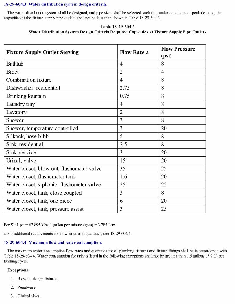
18-29-604.3 Water distribution system design criteria.
The water distribution system shall be designed, and pipe sizes shall be selected such that under conditions of peak demand, thecapacities at the fixture supply pipe outlets shall not be less than shown in Table 18-29-604.3.
Table 18-29-604.3Water Distribution System Design Criteria Required Capacities at Fixture Supply Pipe Outlets
Fixture Supply Outlet Serving Flow Rate a Flow Pressure(psi)
Bathtub 4 8Bidet 2 4Combination fixture 4 8Dishwasher, residential 2.75 8Drinking fountain 0.75 8Laundry tray 4 8Lavatory 2 8Shower 3 8Shower, temperature controlled 3 20Silkock, hose bibb 5 8Sink, residential 2.5 8Sink, service 3 20Urinal, valve 15 20Water closet, blow out, flushometer valve 35 25Water closet, flushometer tank 1.6 20Water closet, siphonic, flushometer valve 25 25Water closet, tank, close coupled 3 8Water closet, tank, one piece 6 20Water closet, tank, pressure assist 3 25
For SI: 1 psi = 67.895 kPa, 1 gallon per minute (gpm) = 3.785 L/m.
a For additional requirements for flow rates and quantities, see 18-29-604.4.
18-29-604.4 Maximum flow and water consumption.
The maximum water consumption flow rates and quantities for all plumbing fixtures and fixture fittings shall be in accordance withTable 18-29-604.4. Water consumption for urinals listed in the following exceptions shall not be greater than 1.5 gallons (5.7 L) perflushing cycle.
Exceptions:
1. Blowout design fixtures.
2. Penalware.
3. Clinical sinks.

4. Service sinks.
5. Emergency showers.
Table 18-29-604.4Maximum Flow Rates and Consumption for Plumbing Fixtures and Fixture Fittings
Plumbing Fixture or Fixture Fitting Maximum Flow Rate or Quantity aLavatory, private 2.5 gpm at 80 psiLavatory, public 0.5 gpm at 80 psiLavatory, public, metering or self-closing 0.5 gallons per metering cycleShower head 2.5 gpm at 80 psiSink faucet 2.5 gpm at 60 psiUrinal 1.0 gallons per flushing cycleWater closet 1.6 gallons per flushing cycle
For SI: 1 gallon = 3.785 L, 1 gpm = 3.785 L/m, 1 psi = 6.895 kPa
a Consumption tolerances shall be determined from referenced standards
18-29-604.4.1 Deliberately omitted.*
* Editor's note - Coun. J. 3-28-01, p. 55444, § 1, did not provide for a Section 18-29-604.4.1.
18-29-604.4.2 Water closets.
Water consumption for water closets listed in the following exceptions shall not be greater than 4 gallons (15 L) per flushing cycle.
Exceptions:
1. Water closets provided for the public in theaters, nightclubs, restaurant, halls, museums, coliseums, arenas, churches, schools,stadiums and similar occupancies.
2. Water closets provided for patients and residents in, hospitals, nursing homes, sanitariums and similar occupancies.
3. Water closets provided for inmates and residents in prisons, asylums, reformatories and similar occupancies.
18-29-604.5 Size of fixture supply.
The minimum size of a fixture supply pipe shall be as shown in Table 18-29-604.5. The fixture supply pipe shall not terminate morethan 30 inches (762 mm) from the point of connection to the fixture. A reduced-size connector installed between the supply pipe andthe fixture shall be of approved type. The supply pipe shall extend to the floor or wall adjacent to the fixture.
Table 18-29-604.5Minimum Sizes of Fixture Water Supply Pipes
Fixture Minimum Pipe Size (inch)Bathtubs: 60" by 32" and smaller 1/2Bathtubs: Larger than 60" by 32" 1/2Bidet 3/8Combination sink and tray 1/2Dishwashing machine (domestic) 1/2

Drinking fountain 1/2Hose bibbs 3/4Kitchen sink 1/2Domestic 3/4Commercial 3/4Laundry, 1, 2 or 3 compartments 1/2Lavatory 3/8Shower, single head 1/2Sinks, flushing rim 3/4Sinks, service 3/4Urinal, flush tank 1/2Urinal, flush valve 1Wall hydrant 3/4Washing machine (automatic) 1/2Water closet, flush tank 1/2Water closet, flush valve 1Water closet, flushometer tank 3/8Water closet, one piece 1/2
For SI: 1 inch = 25.4 mm, 1 foot = 304.8 mm, 1 psi = 6.895 kPa.
18-29-604.5.1 Minimum size.
The minimum size of individual distribution lines utilized in parallel water distribution systems shall be as shown in Table 18-29-604.5.
18-29-604.6 Variable street pressures.
Where street water main pressures fluctuate, the building water distribution system shall be designed for the minimum pressureavailable.
18-29-604.7 Inadequate water pressure.
Wherever water pressure from the street main or other source of supply is insufficient to provide flow pressures at fixture outlets asrequired under Section 18-29-604.3, a water pressure booster system conforming to Section 18-29-606.5 shall be installed on thebuilding water supply system.
18-29-604.8 Water pressure reducing valve or regulator.
Where water pressure within a building exceeds 100 psi (690 kPa) static at any fixture or outlet, an approved water pressurereducing valve conforming to ASSE 1003 with strainer shall be installed to reduce the pressure at any fixture or outlet in the buildingwater distribution piping to 100 psi (690 kPa) static or less.
18-29-604.8.1 Valve design.
The pressure reducing valve shall be designed to remain closed in case of valve failure.
18-29-604.8.2 Repair and removal.
All water pressure reducing valves, regulators and strainers shall be so constructed and installed as to permit repair or removal ofparts without breaking a pipeline or removing the valve and strainer from the pipeline.

18-29-604.9 Deliberately omitted.
18-29-604.10 Size of water supply pipes.
Each main supply pipe, principal supply pipe, branch supply pipe, riser pipe, distributing pipe, or branch distributing pipe shall be of asize which under normal pressure shall deliver a full volume of water to each and all of its outlets.
18-29-604.10.1 Minimum sizes of branch distributing pipes for fixtures and appliances.
The water supply system shall be designed on the basis of the minimum available pressure at the water main or other source ofwater supply. The minimum available pressure will be given by the department of water management for each location.
(Amend Coun. J. 11-8-12, p. 38872, § 350)
18-29-604.10.1.1 Demand load.
The water supply demand load in the distributing system shall be based upon the number, type, and probable simultaneous use of thefixtures to be supplied.
18-29-604.10.1.2 Size of piping.
The size of piping shall be such that the velocity of each flow during maximum demand will not exceed 8 feet (2440 mm) per secondvelocity in the main supply pipe, principal supply pipe, and branch supply pipe. When a water service requires a pump, the velocity offlow in the service shall not exceed 5 feet (1525 mm) per second velocity.
18-29-604.10.1.3 Available pressure.
In determining the available pressure to overcome friction in the piping system, head meter and other losses shall be deducted fromthe minimum available pressure source. When the pressure exceeds 100 psi (690 kPa) at any plumbing fixture, the pressure shall bereduced by an approved type reducing valve. The minimum size of fixture supply pipes are shown in Table 18-29-604.5.
18-29-604.10.2 Procedures for calculating sizing.
See Appendix A for procedures for sizing of the water supply system.
18-29-604.11 Air chambers required.
Air chambers shall be installed at the upper terminals of all upfeed riser pipes and in branch distributing pipes contiguous to, anddirectly above, the connection of such branch distributing pipes to the plumbing fixture or other water-supplied appliance. Such airchambers shall be installed in a direct line with the flow of water through such pipes and shall be of sufficient capacity to provide an aircushion which will absorb shock, stress, or strain or eliminate all excess noises which may be caused by the operation of any valves,faucets, bibbs, or cocks in the water supply system.
18-29-604.11.1 Size of air chamber.
No air chamber which is constructed of pipe shall be of a size less than the pipe which it serves and to which it is connected andshall be not less than 2 feet (610 mm) in length. The air chamber on each water supply branch connection to a plumbing fixture shallbe not less than 12 inches (300 mm) long.
18-29-605 Materials, Joints and Connections.
18-29-605.1 Water compatibility.
Water service pipe and water distribution pipe shall be resistant to corrosive action and degrading action from the potable watersupplied by the water purveyor or individual water supply system.
18-29-605.2 Soil and ground water.
The installation of a water service pipe shall be prohibited in soil and ground water contaminated with solvents, fuels, organiccompounds or other detrimental materials causing permeation, corrosion, degradation or structural failure of the piping material. Wheredetrimental conditions are suspected, a chemical analysis of the soil and ground water conditions shall be required to ascertain theacceptability of the water service material for the specific installation. Where detrimental conditions exist, approved alternativematerials or routing shall be required.
18-29-605.3 Lead content of water supply pipe and fittings.

The maximum led* content of pipe and pipe fittings (including valves and faucets) utilized in the water supply system shall begoverned by the federal Safe Drinking Water Act and applicable U.S.E.P.A. regulations, as amended.
(Amend Coun. J. 11-16-16, p. 37901, Art. IV, § 7)
* Editor's note - As set forth in Coun. J. 11-16-16, p. 37901, Art. IV, § 7; correct language appears to be "lead".
18-29-605.4 Water service pipe.
Water service pipe shall conform to NSF 61 and to one of the standards listed in Table 18-29-605.4. All water service pipe or tubing,installed underground and outside of the structure, shall have a minimum working pressure rating of 160 psi (1100 kPa) at 73.45°F(23.03°C). Where the water pressure exceeds 160 psi (1100 kPa), piping material shall have a minimum rated working pressure equalto the highest available pressure. All ductile iron water pipe shall be cement mortar lined in accordance with AWWA C104.
Table 18-29-605.4Water Service Pipe
Material Standard
Copper or copper-alloy tubing (Type K) ASTM B 75; ASTM B 88; ASTM B 251;ASTM B 447
Ductile iron water pipe AWWA C151; AWWA C115
18-29-605.4.1 Materials for supply pipes and fittings.
All new and replaced water supply pipes and fittings shall be of materials specified in Tables 18-29-605.4, 18-29-605.5 and 18-29-605.6, subject to the restrictions indicated in Column B of the table. Water supply pipe and fittings shall conform to the standards citedin Tables 18-29-605.4, 18-29-605.5 and 18-29-605.6 and to the lead content restrictions specified in Section 18-29-605.3.
(Amend Coun. J. 11-16-16, p. 37901, Art. IV, § 8)
18-29-605.5 Water distribution pipe.
Water distribution pipe shall conform to NSF 61 and shall conform to one of the standards listed in Table 18-29-605.5. All hot waterdistribution pipe and tubing shall have a minimum pressure rating of 100 psi (690 kPa) at 1805°F (825°C).
Table 18-29-605.5Water Distribution Pipe
Material StandardBrass pipe ASTM B 43Chlorinated Polyvinyl Chloride (CPVC)plastic pipe and tubing a
ASTM D 2846; ASTM F 441; ASTM F442; CSA B 137.6
Polypropylene (PP) plastic pipe andtubing a ASTM F 1412
PVDF plastic pipe and tubing a ASTM F 1412Copper or copper-alloy pipe ASTM B 42; ASTM B 302Copper or copper-alloy tubing (Type K,L, or M)
ASTM B 74; ASTM B 88; ASTM B 251;ASTM B 447
Galvanized steel pipe ASTM A 53

a For secondary water used in process applications only.
18-29-605.6 Fittings.
Pipe fittings shall be approved for installation with the piping material installed and shall conform to the respective pipe standards orone of the standards listed in Table 18-29-605.6. All pipe fittings utilized in water supply systems shall also conform to NSF 61. Thefittings shall not have ledges, shoulders or reductions capable of retarding or obstructing flow in the piping. Ductile and gray iron pipefittings shall be cement mortar lined in accordance with AWWA C104.
Table 18-29-605.6Pipe Fittings
Material StandardCast iron ASME B 16.4; ASME B 16.12Polypropylene (PP) plastic pipe andtubing a ASTM F 1412
PVDF plastic pipe and tubing a ASTM F 1412Chlorinated polyvinyl chloride (CPVC)plastic a
ASTM F 437; ASTM F 438; ASTM F439
Copper or copper alloyASME B 16.15; ASME B 16.18; ASMEB 16.22; ASME B 16.23; ASME B 16.26;ASME B 16.29; ASME B 16.32
Gray iron and ductile iron AWWA C 110; AWWA C 153Malleable iron ASME B 16.3
Steel ASME B 16.9; ASME B 16.11; ASME B16.28
a For secondary water used in process applications only.
18-29-605.7 Valves.
All valves shall be compatible with the type of piping material installed in the system.
18-29-605.8 Manufactured pipe nipples.
Manufactured pipe nipples shall conform to the following standards:
1) Steel nipples: ASTM A 733.
2) Brass-plated, copper-plated, or nickel-plated: ASTM B 687
18-29-605.9 Prohibited joints and connections.
The following types of joints and connections shall be prohibited:
1. Cement or concrete joints;
2. Joints made with fittings not approved for the specific installation;
3. Solvent-cement joints between different types of plastic pipe;
4. Saddle-type fittings;
5. Dresser couplings.

18-29-605.10 Deliberately omitted.
18-29-605.11 Deliberately omitted.
18-29-605.12 Brass.
Joints between brass pipe or fittings shall comply with Sections 18-29-605.12 through 18-29-605.12.4.
18-29-605.12.1 Brazed joints.
All joint surfaces shall be cleaned. An approved flux shall be applied where required. The joint shall be brazed with a filler metalconforming to AWS A5.8.
18-29-605.12.2 Mechanical joints.
Mechanical joints shall be installed in accordance with the manufacturer's instructions.
18-29-605.12.3 Threaded joints.
Threads shall conform to ASME B 1.20.1. Pipe- joint compound or tape shall be applied on the male threads only.
18-29-605.12.4 Welded joints.
All joint surfaces shall be cleaned. The joint shall be welded with an approved filler metal.
18-29-605.13 Gray iron and ductile iron joints.
Joints for gray and ductile iron pipe and fittings shall comply with AWWA C111 and shall be installed in accordance with themanufacturer's installation instructions.
18-29-605.14 Copper pipe.
Joints between copper or copper-alloy pipe or fittings shall comply with Sections 18-29-605.14.1 through 18-29-605.14.3.
18-29-605.14.1 Deliberately omitted.
18-29-605.14.2 Deliberately omitted.
18-29-605.14.3 Soldered joints.
Solder joints shall be made in accordance with the methods of ASTM B 828. All cut tube ends shall be reamed to the full insidediameter of the tube end. All joint surfaces shall be cleaned. A flux conforming to ASTM B 813 shall be applied. The joint shall besoldered with a solder conforming to ASTM B 32. The joining of water supply piping shall be made with lead- free solder and fluxes."Lead free" shall mean a chemical composition equal to or less than 0.2 percent lead.
18-29-605.15 Copper tubing.
Joints between copper or copper-alloy tubing or fittings shall comply with Sections 18-29-605.15.1 through 18-29-605.15.4.
18-29-605.15.1 Brazed joints.
All joint surfaces shall be cleaned. An approved flux shall be applied where required. The joint shall be brazed with a filler metalconforming to AWS A5.8.
18-29-605.15.2 Flared joints.
Flared joints for water pipe shall be made by a tool designed for that operation.
18-29-605.15.3 Mechanical joints.
Mechanical joints shall be installed in accordance with the manufacturer's instructions.
18-29-605.15.4 Soldered joints.
Solder joints shall be made in accordance with the methods of ASTM B 828. All cut tube ends shall be reamed to the full insidediameter of the tube end. All joint surfaces shall be cleaned. A flux conforming to ASTM B 813 shall be applied. The joint shall besoldered with a solder conforming to ASTM B 32. The joining of water supply piping shall be made with lead- free solders and fluxes.

"Lead free" shall mean a chemical composition equal to or less than 0.2 percent lead.
18-29-605.16 CPVC plastic.
Joints between CPVC plastic pipe or fittings shall comply with Sections 18-29-605.16.1 through 18-29-605.16.3 (For use onsecondary water piping in process applications only).
18-29-605.16.1 Mechanical joints.
Mechanical joints shall be installed in accordance with the manufacturer's instructions.
18-29-605.16.2 Solvent cementing.
Joint surfaces shall be clean and free from moisture and an approved primer shall be applied. Solvent cement, orange in color andconforming to ASTM F 493, shall be applied to all joint surfaces. The joint shall be made while the cement is wet, and in accordancewith ASTM D 2846 or ASTM F 493. Solvent-cement joints shall be permitted above or below ground.
18-29-605.16.3 Threaded joints.
Threads shall conform to ASME B 1.20.1. Schedule 80 or heavier pipe shall be permitted to be threaded with dies specificallydesigned for plastic pipe, but the pressure rating of the pipe shall be reduced by 50 percent. Thread by socket molded fittings shall bepermitted. Approved thread lubricant or tape shall be applied on the male threads only.
18-29-605.17 Steel.
Joints between galvanized steel pipe or fittings shall comply with Sections 18-29-605.17.1 and 18-29-605.17.2.
18-29-605.17.1 Threaded joints.
Threads shall conform to ASME B 1.20.1. Pipe- joint compound or tape shall be applied on the male threads only.
18-29-605.17.2 Mechanical joints.
Joints shall be made with an approved elastomeric seal. Mechanical joints shall be installed in accordance with the manufacturer'sinstructions.
18-29-605.18 Deliberately omitted.
18-29-605.19 Deliberately omitted.
18-29-605.20 Deliberately omitted.
18-29-605.21 Joints between different materials.
Joints between different piping materials shall be made with a mechanical joint of the compression or mechanical-sealing type, or aspermitted in Section 18-29-605.21.1.
18-29-605.21.1 Copper or copper-alloy tubing to galvanized steel pipe.
Joints between copper or copper-alloy tubing and galvanized steel pipe shall be made with a brass converter fitting or dielectricfitting. The copper tubing shall be soldered to the fitting in an approved manner, and the fitting shall be screwed to the threaded pipe.
18-29-605.22 Protection for pipes and fixtures.
All new concealed water pipes, storage tanks, flushing services or systems and all pipes or tanks exposed to low temperatures shallbe protected from freezing.
18-29-605.23 Hydrants and non-freeze hydrants protection.
Every hydrant providing drinking water shall be protected from surface water and ground contamination.
18-29-605.24 Water supply pipe protection.
All water supply pipes or distributing pipes that are installed in the ground in any public way or other public place or in buildings,structures, or privately owned premises shall be covered to a minimum depth of not less than 5 feet (1525 mm) below the surface ofthe ground. No ashes, cinders, or refuse shall be used in back-filling any trenches or excavations in which water pipes are installed. Allsuch pipes shall be coated with coal tar paint and insulated where they pass through concrete floors, or new concrete or masonry

walls.
18-29-605.25 Refrigerant condensers.
No refrigerant condenser of the water jacket type with a common wall between the refrigerant gas and the cooling water shall bedirectly connected to the city water supply. Cooling water, if from the city water supply, shall be obtained by gravity through anindirect connection. If water under pressure is required, it may be supplied only by means of a reduced pressure backflow preventer.
18-29-605.26 Dead-ends prohibited.
Unused sections of water supply piping systems (or so called dead-ends) where city water will become stagnant are prohibited otherthan fire protection systems protected and installed in accordance with Table 18-29-608.1.
18-29-605.27 Air conditioning and refrigeration systems.
All new or newly remodeled refrigeration systems employing water from the city mains for condensing purposes in the process ofproviding space air conditioning for commercial, industrial or residential use shall be closed air conditioning systems employingrecirculation of cooling water to conserve water.
18-29-605.28 Permissible exceptions.
Any and all exceptions to this provision will be permitted only by action of the commissioner of water management.
(Amend Coun. J. 11-8-12, p. 38872, § 351)
18-29-606 Installation of the Building Water Distribution System.
18-29-606.1 Location of full-open valves.
Full-open valves shall be installed in the following locations:
1. On the building water service pipe from the public water supply near the curb;
2. On the water distribution supply pipe at the entrance into the structure;
3. On the discharge side of every water meter;
4. On the base of every water riser pipe in occupancies other than multiple family residential occupancies that are two stories orless in height and in one- and two-family residential occupancies etc.;
5. On the top of every water down-feed pipe in occupancies other than one- and two-family residential occupancies;
6. On the entrance to every water supply pipe to a dwelling unit, except where supplying a single fixture equipped with individualstops;
7. On the water supply pipe to a gravity or pressurized water tank;
8. On the water supply pipe to every water heater.
18-29-606.2 Location of shutoff valves.
Shutoff valves shall be installed in the following locations:
1. On the fixture supply to each plumbing fixture except one- and two-family or multiple family residential occupancies, or individualguestrooms that are provided with unit shutoff valves in hotels, motels, boarding houses and similar occupancies;
2. On the water supply pipe to each sillcock;
3. On the water supply pipe to each appliance or mechanical equipment; and
4. On water services 1 1/2 inches (40 mm) or larger requiring meters either in the building or in a meter vault, valves shall beinstalled on the inlet and outlet sides of the meter and as near as practicable thereto. Meters on 1-inch (25 mm) services have a valveon the inlet side only. Valves located in the meter vault shall not eliminate the need for the valve in the building. All such valves shall beaccessible for operation at all times.
18-29-606.3 Access to valves.

Access shall be provided to all required full-open valves and shutoff valves.
18-29-606.4 Valve identification.
Service and hose bibb valves shall be identified. All other valves installed in locations that are not adjacent to the fixture or applianceshall be identified, indicating the fixture or appliance served.
18-29-606.5 Water pressure booster systems.
Water pressure booster systems shall be provided as required by Sections 18-29-606.5.1 through 18-29-606.5.10.
18-29-606.5.1 Hydropneumatic system, booster pump system, gravity tank.
When the water pressure in the city water main is insufficient to furnish an adequate water supply for any purpose in any building,structure or premises, a hydropneumatic system, booster pump system, or gravity tank shall be installed.
18-29-606.5.1.1 Requirements.
All hydropneumatic systems shall consist of a water pump or pumps and a pressure tank and shall be provided with controls to insurecomplete automatic operation. The material and construction of the tank shall be in accordance with the ASME Rules for theConstruction of Unfired Pressure Vessels, Section VIII dated 1973.
18-29-606.5.1.1.1 Pressure relief valve.
Each pump serving such tanks shall have a pressure relief valve on the discharge side capable of relieving water pressure in excessof the designed working pressure of such tanks.
18-29-606.5.1.1.2 Compression tank.
Each compression tank shall be so connected that the air content thereof shall be no less than 25 percent of its total capacity. Eachcompression tank shall be provided with a sludge drain pipe which shall be connected to such tank at the lowest level of the bottomsection thereof and shall discharge through an indirect connection into the drainage system with a minimum air gap of 6 inches (150mm).
18-29-606.5.1.1.3 Sludge drain pipe.
Each sludge drain pipe shall be equal in size to the inlet pipe but need not exceed 2 inches (50 mm) and shall be provided with acontrol valve having a clear waterway equal in area to that of the sludge drain pipe.
18-29-606.5.1.2 Booster pump system.
Booster pump systems may be of the constant speed type or the variable frequency drive type. Each pump or pumps shall havesufficient capacity to furnish an adequate supply of water for any purpose. When one pump is installed it shall run continuously orwhen a multipump system is installed the lead pump shall run continuously. A pressure reducing valve shall be installed on thedischarge side of each constant speed pump.
18-29-606.5.1.2.1 Gravity tanks.
Gravity tanks operating at atmospheric pressure shall be installed as required by Section 18-29-606.5.4.
18-29-606.5.1.2.2 Total pressure.
The water piping system and equipment supplied by the systems enumerated in this section shall be capable of withstanding the totalpressure developed by any such system at any elevation in which these pressures occur.
18-29-606.5.1.2.3 Low pressure cutoff.
When a pump is directly connected to a city water main, a low pressure cutoff switch on the pump shall be installed to prevent thecreation of pressures less than 5 psi (35 kPa) on the suction side of the water system and within 5 feet (1525 mm) of the pump suctioninlet, and a pressure gauge shall be installed between the shutoff valve and pump.
Exception: Fire pumps.
18-29-606.5.2 Surge tank for pumps.
When a water system in any building, structure or premises is supplied with other than city water or is equipped for service other

than from the city mains or which is supplied with city water which has been previously used for any purpose, each service from thecity water system shall enter through a receiving tank for the purpose of preventing water from the secondary system from flowingback into the city mains.
18-29-606.5.3 Check valves required.
Check valves which are noiseless in their operation and air chambers of sufficient air cushion capacity shall be installed in thesuction pipe and the discharge pipe of each house pump, or other water pressure increasing device. Where such check valves are ofthe slow-acting type and the operation thereof entirely eliminates the shocks, strains, stresses, and excess noises caused by theoperation of such pump or device, the installation of air chambers may be dispensed with.
18-29-606.5.3.1 Approval required.
No check valve shall be installed unless the design and construction thereof shall first have been approved by the commissioner ofwater management.
(Amend Coun. J. 11-8-12, p. 38872, § 352)
18-29-606.5.4 Equipment required for tanks receiving city water.
All surge tanks, receiving reservoirs, gravity storage tanks, house storage tanks, or tanks of any description used for receiving orstoring city water at atmospheric pressure, shall be supplied an approved slow-acting automatic control valve. The discharge outlet ofthe control valve shall be directly connected to the receiving unit at a distance of 6 inches (150 mm) above the top of a horizontaloverflow pipe. For a vertical overflow pipe, the distance shall be 6 inches (150 mm) plus the diameter of the overflow pipe. Theoverflow pipe connection shall have an area of not less than twice that of the supply opening.
18-29-606.5.4.1 Sludge drain pipe.
Each tank used for receiving or storing city water shall be provided with a sludge drain pipe which shall be connected to the tank atthe lowest level of the bottom section thereof and shall discharge through an indirect connection to the drainage system with aminimum air gap of 6 inches (150 mm).
18-29-606.5.4.2 Size.
Each sludge drain pipe shall be equal in size to the inlet pipe but need not exceed 2 inches (50 mm) and shall be provided with acontrol valve with a clear waterway equal in area to that of the sludge drain pipe.
18-29-606.5.4.3 Covers and support.
Such tanks shall have bolted watertight covers of the same material as the tank and shall be located and housed to prevent externalpollution. The building commissioner shall approve the support for all such tanks before the permit is issued.
(Amend Coun. J. 3-5-03, p. 104990, § 48; Amend Coun. J. 11-13-07, p. 14999, Art. II, § 1)
18-29-606.5.5 Recycling system for vehicle wash installations.
All new or newly remodeled commercial and industrial vehicle wash installations shall be equipped with a water recycling system toconserve water. The system shall be composed of a water reuse tank and all necessary piping to insure the cycling of water for morethan one washing operation.
18-29-606.5.6 Potable water inlet control and location.
Potable water inlets to gravity tanks shall be controlled by a ball cock or other automatic supply valve to prevent the tank fromoverflowing. The inlet shall be terminated as to provide an air gap not less than 4 inches (100 mm) above the overflow.
18-29-606.5.7 Tank drain pipes.
A valved pipe shall be provided at the lowest point of each tank to permit emptying of the tank. The tank drain pipe shall dischargeas required for overflow pipes.
18-29-606.5.8 Prohibited location of potable supply tanks.
Potable water gravity tanks or manholes of potable water pressure tanks shall not be located directly under any soil or waste pipingor any source of contamination.

18-29-606.5.9 Pressure relief valve requirements.
Each pressure relief valve shall be a minimum of 3/4 inch (20 mm) and shall be equipped with a test lever. In addition, an automaticvacuum relief valve shall be installed on such tanks with a 24-mesh screen of bronze or stainless steel. The area of the screening shallbe 50 percent greater than the opening it serves. All equipment of a hydropneumatic system shall be capable to withstand the designedworking pressure.
Exception: This section shall not apply to pressurized captive air diaphragm/bladder tanks.
18-29-606.5.10 Pressure relief valves for hydropneumatic tanks.
Every pressure tank in a hydropneumatic pressure booster system shall be protected with a pressure relief valve. The pressure reliefvalve shall be set at a maximum pressure equal to the rating of the tank. The relief valve shall be installed on the supply pipe to thetank or on the tank. The relief valve shall discharge by gravity to a safe place of disposal.
18-29-606.6 Test of distribution pipes.
The entire water distribution system within buildings shall be tested in the presence of a plumbing inspector utilizing a water or airpressure test. All piping, fittings, valves and equipment except any atmospheric tank shall be tested to 1 1/2 times its designed pressurebut not less than 100 psi (690 kPa). When the test pressure exceeds 100 psi (690 kPa) only a hydrostatic test shall be given.
18-29-607 Hot Water Supply System.
18-29-607.1 Where required.
In occupied structures, hot water shall be supplied to all plumbing fixtures and equipment utilized for bathing, washing, culinarypurposes, cleansing, laundry or building maintenance. Every sink and lavatory shall be supplied with hot and cold water. No waterexceeding 140°F (60°C) shall discharge into any lavatory, sink, tub or shower.
Exception: In nonresidential occupancies, hot water or tempered water shall be supplied for bathing and washing purposes.Tempered water shall be delivered from accessible hand-washing facilities.
18-29-607.1.1 Water temperature.
All lavatory faucets for public use shall be provided with an automatic safety water mixing device to prevent sudden unanticipatedchanges in water temperature or excessive water temperatures. The automatic safety water mixing device shall be either thermostatic,pressure balance or combination controlled, in accordance with ANSI/ASSE 1016 or 1017, ASSE-1066 adjusted to a maximum settingof 115°F (46°C) at the time of installation.
18-29-607.1.2 Shower compartments and shower- bath combinations.
All shower compartments and shower-bath combinations shall be provided with an automatic safety water mixing device to preventsudden unanticipated changes in water temperature or excessive water temperatures. The automatic safety water mixing device shallbe either thermostatic, pressure balance, or combination controlled, in accordance with ANSI/ASSE 1016 and designed with amaximum handle rotation limit/stop, adjusted to a maximum setting of 115°F (46.1°C).
18-29-607.1.2.1 Mixed water temperature.
The temperature of mixed water provided to multi- shower units or gang showers shall be controlled by a master automatic safetywater mixing device or individually regulated by automatic safety mixing valves for each shower unit. A hot water heater thermostatshall not be an acceptable alternative water temperature control device.
18-29-607.2 Heated plumbing circulating system.
Hot water supply systems in buildings other than one-family and two-family dwellings shall be of the return circulation type inbuildings where the developed length of hot water piping, from the source of hot water supply to the farthest fixture supplied, exceeds100 feet (30.5 m).
18-29-607.2.1 Return piping.
The return piping shall be sized for a maximum temperature drop of 20°F (6.67°C) for forced circulation systems and 40°F (4.44°C)for gravity circulation systems. Such piping may be of the upfeed system, downfeed system or the combination upfeed and downfeedsystems and shall be installed as follows:

1. For upfeed systems, the return circulation pipe shall connect so the supply risers below the top-most supply branch to fixturesand not more than 12 inches (300 mm) below.
2. For downfeed systems and combination upfeed and downfeed systems, the return circulation pipe shall connect to the base ofeach downfeed riser.
3. For inverted downfeed systems, the return circulation pipe shall connect to the supply risers above the lowest supply branch tofixtures and not more than 12 inches (300 mm) above.
4. For inverted upfeed systems and inverted combination downfeed and upfeed systems, the return circulation pipe shall connect tothe top of the riser above the highest fixture.
5. Return circulation pipes shall connect to the water heater or storage tank. Each return circulation riser branch shall be providedwith a shutoff valve and check valve. Where more than one return circulation riser connects to a return main, each return circulationriser branch shall be provided with a shutoff valve, check valve and balancing valve or a check valve and combination shutoffbalancing valve. All trapped piping shall be provided with an automatic air vent at the highest point.
18-29-607.2.1A Piping insulation.
Piping in required return circulation systems shall be insulated to provide a thermal resistance, R, excluding film resistances, of
R= [t1-t0(hr)(Ft2)°F.]/Btu
25
For SI: R = [t1 - t0(0.0304)K x m2]/W
where t1 - t0 is the design temperature differential between the water in the pipe and the surrounding air in degrees Fahrenheit (°F).
Exception: Pipe insulation is not required where t1 - t0 is 25°F (14°C) or less.
(Amend Coun. J. 11-9-16, p. 36266, § 37)
18-29-607.2.2 Pump operation.
Where a circulating pump is installed on a return circulation hot water system, the pump shall be arranged to shut off automaticallyor to allow manual shut off when the hot water system is not in operation.
18-29-607.3 Thermal expansion control.
A means of controlling increased pressure caused by thermal expansion shall be provided where required in accordance withSections 18-29-607.3 and 18-29-607.3.2.
18-29-607.3.1 Pressure reducing valve.
For water service system sizes up to and including 2 inches (50 mm), a device for controlling pressure shall be installed wherethermal expansion has caused the pressure on the downstream side of a pressure reducing valve to exceed the main supply pressure.A pressure reducing valve with an integral bypass check valve or other device shall be installed to satisfy this requirement.
18-29-607.3.2 Backflow prevention device or check valve.
Where a backflow prevention device, check valve or other device is installed on a water supply system utilizing storage waterheating equipment such that thermal expansion causes an increase in pressure, a device for controlling pressure shall be installed.
18-29-607.4 Hot water supply to fixtures.
The hot water supply to any fixture requiring hot water shall be installed on left side of the fixture.
18-29-607.5 Expansion joints.
Mechanical expansion joints shall be accessible and may be used where necessary to provide for expansion and contraction of thepipes. For hot water piping, the expansion function shall be provided by the flexing of the piping material with expansion loops or swingjoints. The piping shall be properly anchored and installed as follows:
1. Each hot water riser shall be provided with anchors at a maximum distance of 100 feet (30.5 m) or less with an expansion loopof required length provided between such anchors.

2. Each hot water main shall be provided with anchors at a maximum distance of 100 feet (30.5 m) or less with an expansion loopof required length provided between such anchors. Offsets of 90 degrees in a horizontal main shall be of required length to absorbexpansion by flexure.
3. Branches from mains connected to risers shall be provided with a swing joint of required length unless the branch is of adequatelength to absorb expansion by flexure.
4. Branches from risers to fixtures shall be provided with a swing joint of required length unless the branch is of adequate length toabsorb expansion by flexture.
18-29-607.6 Prohibited connections.
Any water pipe connection to any pump or other appliance through which any vibration, shock, strain, stress, or pulsation mayeffectuate a water hammer is prohibited. Any excess noises or sounds in the water supply system of any building or structure that maybe communicated through such connection or service pipe of the Chicago Waterworks System is also prohibited.
18-29-608 Protection of Potable Water Supply.
18-29-608.1 General.
A potable water supply system shall be designed, installed and maintained in such a manner so as to prevent contamination fromnonpotable liquids, solids or gases being introduced into the potable water supply through cross-connections or any other pipingconnections to the system. Backflow preventer applications shall conform to Table 18-29-608.1.
Table 18-29-608.1Application for Backflow Preventers
For a printer-friendly PDF version of Table 18-29-608.1, please click here.
Device Degree ofHazard a Application b Applicable
Standards
Air gap c High or lowhazard
Backsiphonage orbackpressure
ASMEA112.1.2
Antisiphon-type Water ClosetFlush Tank Ball Cock Low Hazard Backsiphonage only
ASSE 1002CSACAN/CSA-B125
Reduced Pressure PrincipleBackflow Preventer
High or lowhazard
Backpressure orbacksiphonageSizes 1/4" to 10"
ASSE 1013AWWA C511CSACAN/CSAB64.4
Reduced Pressure DetectorAssembly Backflow Preventer
High or lowhazard
Backsiphonage orbackpressure ASSE 1047
Double Check BackflowPrevention Assembly Low hazard
Backpressure orbacksiphonageSizes 3/8" to 16"
ASSE 1015AWWA C510
Double Check DetectorBackflow Preventer Assembly Low hazard
Backpressure orbacksiphonage(Fire sprinklersystems)
ASSE 1048

Sizes 1 1/2" - 16"
Dual Check Valve-TypeBackflow Preventer Low hazard
Backpressure orbacksiphonageSizes 1/4" - 1"
ASSE 1024
Backflow Preventer withIntermediate AtmosphericVents
Low hazardBackpressure orbacksiphonageSizes 1/4" - 3/4"
ASSE 1012CSACAN/CSA-B64.3
Dual Check Valve-TypeBackflow Preventer forCarbonated BeverageDispensers/Post Mix Type
Low hazardBackpressure orbacksiphonageSizes 1/4" - 3/8"
ASSE 1032
Pipe-Applied Atmospheric-Type Vacuum Breaker
High or lowhazard
Backsiphonage onlySizes 1/4" - 4"
ASSE 1001CSACAN/CSA-B64.1.1
Pressure Vacuum BreakerAssembly
High or lowhazard
Backsiphonage onlySizes 1/2" - 2" ASSE 1020
Hose-connection VacuumBreaker
High or lowhazard
BacksiphonageSizes 1/2", 3/4", 1"
ASSE 1011CSACAN/CSA-B64.2
Vacuum Breaker WallHydrants, Frost-Resistant,Automatic Draining Type
High or lowhazard
BacksiphonageSizes 3/4", 1"
ASSE 1019CSACAN/CSA-B64.2.2
Laboratory Faucet BackflowPreventer(Non-testable)
Low hazard Backsiphonage ASSE 1035CSA B64.7
Hose Connection BackflowPreventer(Non-testable)
Low hazard
Low headbackpressure, ratedworking pressurebackpressure orbacksiphonageSizes 1/2" - 1"
ASSE 1052
Spill-proof vacuum breaker High or lowhazard
Backsiphonage onlySizes 1/4" - 2" ASSE 1056
For SI: 1 inch = 25.4 mm
a Low Hazard - See Pollution (Section 202) and Department of Water Management requirements
High Hazard - See Contamination (Section 202) and Department of Water Management requirements
b See Backpressure (Section 202)

See Backpressure, Low Head (Section 202)
See Backsiphonage (Section 202)
c Break tank
d For systems using non-food grade chemical additives
(Amend Coun. J. 11-8-12, p. 38872, § 353)
18-29-608.2 Plumbing fixtures.
The supply lines or fittings for every plumbing fixture shall be installed so as to prevent backflow.
18-29-608.3 Water supply pipes.
Water supply pipe to plumbing fixtures, water using appliances and equipment, wall hydrants (except fire hydrants used for firefighting) and hose bibbs shall meet the following requirements:
1. No plumbing fixture shall be installed unless the water supply enters said fixture with an air gap of twice the internal diameter ofthe water supply pipe but not less than 1 inch (25 mm) above the flood level rim of the fixture, except for fixtures listed in Section 18-29-423 of this article.
(Amend Coun. J. 11-9-16, p. 36266, § 37)
2. Dishwashing machine and clothes washing machine water supply pipes shall have an air gap as required for plumbing fixtures,except that dishwashing machine water supply pipes may enter through an approved atmospheric vacuum breaker located on thedischarge side of the last control valve. The bottom of the vacuum breaker shall not be less than 6 inches (150 mm) above the floodlevel rim of the machine or related equipment.
18-29-608.3.1 Special equipment, water supply protection.
The water supply for hospital fixtures shall be protected against backflow with a reduced pressure principle backflow preventer, anatmospheric vacuum breaker, or an air gap. Vacuum breakers for bedpan washer hoses shall not be located less than 5 feet (1525mm) above the floor.
18-29-608.4 Deliberately omitted.
18-29-608.5 Secondary water.
See Article 2 for definition. For materials for secondary water refer to Table 18-29-605.5, Water Distribution Pipe.
18-29-608.6 Prohibited use of secondary water.
No secondary water shall overflow or be discharged into any surge tank, storage tank, or reservoir, or shall in any way be piped orconveyed into the water supply system or into any building, structure, or premises, such that the overflow or discharge contaminatesthe fresh water supply from the mains of the Chicago Waterworks System either inside of the premises or in the water service pipe.Secondary water shall not be piped to or used in any plumbing fixture, or for cooling crushers, rollers, or mixers where foods, candies,liquids or materials are manufactured for human or animal consumption.
In accordance with Section 11-8-390 of this Code, the installation of any potable water supply well after May 14, 1997 is prohibitedexcept as otherwise permitted in that section.
(Amend Coun. J. 3-27-02, p. 82090, § 3)
18-29-608.6.1 Private water supplies.
Cross-connections between a private water supply and a potable public supply shall be prohibited.
18-29-608.7 Stop-and-waste valves prohibited.
Combination stop-and-waste valves or cocks shall not be installed underground.
18-29-608.8 Identification of potable and nonpotable water.
In all buildings where two or more water distribution systems (one potable water and the other nonpotable water) or secondary

water distribution systems are installed, each system shall be identified either by color marking or metal tags as required by ASMEA13.1.
18-29-608.9 Re-utilization prohibited.
Water utilized for the cooling of equipment of other processes shall not be returned to the potable water system. Such water shall bedischarged into a drainage system through an air gap or shall be utilized for nonpotable purposes.
18-29-608.10 Reuse of piping.
Piping that has been utilized for any purpose other than conveying potable water shall not be utilized for conveying potable water.
18-29-608.11 Painting of water tanks.
The interior surface of a potable water tank shall not be lined, painted or repaired with any material that changes the taste, odor,color or potability of the water supply when the tank is placed in, or returned to, service.
18-29-608.12 Pumps and other appliances.
Water pumps, filters, softeners, tanks and all other devices that handle or treat potable water shall be protected againstcontamination.
18-29-608.13 Backflow protection.
Means of protection against backflow shall be provided in accordance with Sections 18-29-608.13.1 through 18-29-608.13.6.
18-29-608.13.1 Air gap.
The minimum required air gap shall be measured vertically from the lowest end of a potable water outlet to the flood level rim of thefixture or receptacle into which such potable water outlet discharges.
18-29-608.13.2 Reduced pressure principle backflow preventers.
Reduced pressure principle backflow preventers shall conform to ASSE 1013, AWWA C511 or CSA CAN/CSA-B64.4. Thesedevices shall be permitted to be installed in areas subject to continuous pressure conditions. The relief opening shall discharge by airgap and shall be prevented from being submerged.
18-29-608.13.3 Backflow preventer with intermediate atmospheric vent.
Backflow preventers with intermediate atmospheric vents shall conform to ASSE 1012 or CSA CAN/CSA- B64.3. These devicesshall be permitted to be installed in areas subject to continuous pressure conditions. The relief opening shall discharge by air gap andshall be prevented from being submerged.
18-29-608.13.4 Barometric loop.
Barometric loops shall precede the point of connection and shall extend vertically to a height of 35 feet (10.67 m). A barometric loopshall only be utilized as an atmospheric-type or pressure-type vacuum breaker.
18-29-608.13.5 Atmospheric-type vacuum breakers.
Pipe-applied atmospheric-type vacuum breakers shall conform to ASSE 1001 or CSA CAN/CSA- B64.1.1. Hose-connectionvacuum breakers shall conform to ASSE 1011, CSA CAN/CSA-B64.2, ASSE 1019, CSA CAN/CSA-B64.2.2, ASSE 1035, CSAB64.7 or ASSE 1052. These devices shall operate wider normal atmospheric pressure when the critical level is installed at the requiredheight.
18-29-608.13.6 Double check-valve assemblies.
Double check-valve assemblies shall conform to ASSE 1015 or AWWA C510. Double-detector check-valve assemblies shallconform to ASSE 1048. These devices shall be capable of operating under continuous pressure conditions.
18-29-608.14 Location of backflow preventers.
Access shall be provided to backflow preventers as specified by the installation instructions of the approved manufacturer.
18-29-608.15 Protection of potable water outlets.

All potable water openings and outlets shall be protected against backflow in accordance with the following:
1. Openings and outlets shall be protected by an air gap between the opening and the fixture flood level rim as specified in Table18-29-608.15.1. Openings and outlets equipped for hose connection shall be protected by means other than an air gap.
2. Openings and outlets shall be protected by a reduced pressure principle backflow preventer.
3. Openings and outlets shall be protected by a backflow preventer with an intermediate atmospheric vent.
4. Openings and outlets shall be protected by atmospheric-type vacuum breakers. The critical level of the vacuum breaker shall beset a minimum of 6 inches (150 mm) above the flood level rim of the fixture or device. Ball cocks shall be set in accordance withSection 425.3.1. Vacuum breakers shall not be installed under exhaust hoods or similar locations that will contain toxic fumes orvapors. Pipe-applied vacuum breakers shall be installed not less than 6 inches (150 mm) above the flood level rim of the fixture,receptor or device served.
5. All pull-out spout-type faucets shall be in compliance with CSA CAN/CSA-B 125 and have an integral vacuum breaker or ventto atmosphere in their design or shall require a dedicated deck- or wall-mounted vacuum breaker. Approved deck-mounted orequipment-mounted vacuum breakers and faucets with integral atmospheric or spill-proof vacuum breakers shall be installed inaccordance with the manufacturer's instructions and the requirements for labeling with the critical level not less than, 1 inch (25 mm)above the flood level rim.
6. Sillcocks, hose bibbs, wall hydrants and other openings with a hose connection shall be protected by an atomospheric-type orpressure type vacuum breaker or a permanently attached hose connection vacuum breaker.
Exceptions:
1. This section shall not apply to water heater and boiler drain valves that are provided with hose connection threads and that areintended for only tank or vessel draining.
2. This section shall not apply to water supply valves intended for connection of clothes washing machines where backflowprevention is otherwise provided or is integral with the machine.
Table 18-29-608.15.1Minimum Required Air Gaps
FixtureMinimum Air GapAway from awall a (inches)
Close to a wall(inches)
Lavatories and other fixtures witheffective opening not greater than 1/2inch in diameter
1 1 1/2
Sink, laundry trays, gooseneck backfaucets and other fixtures with effectiveopenings not greater than 3/4 inch indiameter
1 1/2 2 1/2
Over-rim bath fillers and other fixtureswith effective openings not greater than1 inch in diameter
2 3
Drinking water fountains, single orificenot greater than 7/16 inch in diameter ormultiple orifices with a total area of0.150 square inch (area of circle 7/16inch in diameter).
1 1 1/2

Effective openings greater than 1 inch.Two times thediameter of theeffective opening.
Three times thediameter of theeffective opening.
For SI: 1 inch = 25.4 mm.
a Applicable where walls or obstructions are spaced from the nearest inside edge of the spout opening a distance greater than threetimes the diameter of the effective opening for a single wall, or a distance greater than four times the diameter of the effective openingfor two intersecting walls.
18-29-608.16 Connections to the potable water system.
Connections to the potable water system shall conform to Sections 18-29-608.16.1 through 18-29-608.16.6.
18-29-608.16.1 Beverage carbonator.
Every water supply pipe servicing a beverage carbonator shall receive its supply through a receiving tank constructed in accordancewith Section 18-29-606.5.4 of this Article or shall have installed in the pipe an approved stainless steel in-line-pressure-type backflowpreventer consisting of two check valves separated by an open air port conforming to ASSE 1012 or ASSE 1022. The air port shall notbe directly connected to the drainage system.
18-29-608.16.1.1 Backflow preventer.
The backflow preventer shall be installed in an accessible location on the discharge side of the carbonator water supply valve. Nocopper tube or pipe or copper lined components shall be used for the receiving tank or its piping to the carbonator or the outlet of thestainless backflow preventer.
18-29-608.16.2 High-pressure steam boilers.
Steam boilers exceeding a pressure of 15 psi (103.4 kPa) and hydronic heating systems designed to exceed a pressure of 15 psi(103.4 kPa) or a temperature of 250°F (121°C) shall not be directly connected to the water supply system. Steam boilers notexceeding a pressure of 15 psi (103.4 kPa) and hydronic heating systems designed not to exceed pressure of 30 psi (306.9 kPa) or atemperature of 250°F (121°C) shall be provided with an in-line pressure-type backflow preventer consisting of two check valvesseparated by an open air port. The air port shall not be directly connected to the drainage system. The backflow preventer shall beinstalled in an accessible location on the discharge side of the boiler water supply valve and on the inlet side of the boiler feed valve.
18-29-608.16.3 Connections to automatic fire sprinkler systems and standpipe systems.
The potable water supply to automatic fire sprinkler and standpipe systems shall be protected against backflow by a testable doubledetector check-valve assembly.
18-29-608.16.4 Fire protection equipment, risers, standpipes, tanks to be drained and flushed.
All fire protection equipment, tanks, risers, standpipes, domestic house tanks, compression tanks and all other tanks that have aweight check valve for backflow prevention and are supplied with water from the Chicago Waterworks System shall be drained andflushed at least every 12 months in the presence of a plumbing inspector. Further, fire protection systems and equipment shall be keptfree from accumulations of sand, silt, and stagnant water which would nullify the action of the chlorine content of city water.
18-29-608.16.5 Fire-extinguishing equipment cross-connection.
Any building, premises, material or storage yard which receives service from the Chicago Waterworks System shall not have asiamese or other connection for fire extinguishing purposes installed near any river, lake, or waterway where a city fire boat or city fireengine or pump may pump river, lake or shore water into the city water pipes through a cross-connection of any kind.
18-29-608.16.5.1 Prohibitions.
No stationary pump or privately owned fire equipment shall be maintained for emergency use which draws water from rivers, lakes,and waterways nor shall they use cisterns or wells adjacent to the rivers, lakes and waterways unless protected from cross-connections to city water systems.
18-29-608.16.6 Chemical or petroleum pressure vessels.

Chemical, contaminated water, or sewage lines or vessels shall comply with Sections 18-29-608.16.6.1 through Section 18-29-608.16.6.3.
18-29-608.16.6.1 Chemical or petroleum pressure vessels.
No person, corporation or firm shall connect any pressure vessel to the city water supply. This includes a storage tank, tank car, tanktruck or trailer or other miscellaneous pressurized tank or cylinder containing or having contained liquefied gaseous petroleum productsor other liquefied gaseous chemicals.
18-29-608.16.6.2 Water flushing or cooling.
Water for flushing or cooling (or to be otherwise instilled into such a vessel) shall be obtained by gravity through an indirectconnection. If water under pressure is required, it may be supplied only by means of an auxiliary pump taking suction from a suctiontank provided for this purpose only, with an over-rim supply having an indirect connection.
18-29-608.16.6.3 Chemical, contaminated water, or sewage lines or vessels.
There shall be no direct connection between the city water lines and lines, equipment or vessels containing raw or contaminatedwater, contaminating chemicals or sewage. Such connections shall be made only through an indirect connection.
(Amend Coun. J. 11-8-12, p. 38872, § 354)
18-29-608.16.7 Deliberately omitted.
18-29-608.16.8 Portable cleaning equipment.
Where the portable cleaning equipment (including power washers) connects to the water distribution system, the water supplysystem shall be protected against backflow in accordance with Section 18-29-608.13.1, Section 18-29-608.13.2, Section 18-29-608.13.3, Section 18-29-608.14 or Section 18-29-608.15.
18-29-608.16.9 Dental pump equipment.
Where dental pumping equipment connects to the water distribution system, the water supply system shall be protected againstbackflow in accordance with Section 18-29-608.13.1, Section 18-29-608.13.5, Section 18-29-608.13.6 or Section 18-29-608.15.
18-29-608.17 Private water supplies.
Private water supplies shall be in accordance with Sections 18-29-608.17.1 through 18-29-608.17.1.2.
18-29-608.17.1 Well locations.
A potable ground water source or pump suction line shall not be located closer to potential sources of contamination than thedistances shown in Table 18-29-608.17.1. In the event the underlying rock structure is limestone or fragmented shale, the local or statehealth department shall be consulted on well site location.
Table 18-29-608.17.1Distance from Sources of Contamination to Private Water Supplies and Pump Suction Lines
Source of Contamination Distance (feet)Barnyard 100Farm silo 25Pasture 100Pumphouse floor drain of cast iron draining toground surface 2
Seepage pits 50Septic tank 25Sewer 10

Subsurface disposal fields 50Subsurface pits 50
For SI: 1 foot = 304.8 mm.
18-29-608.17.1.1 Distances.
The distances outlined in Table 18-29-608.17.1 constitute minimum separation and shall be increased in areas of creviced rock orlimestone, or when the direction of movement of ground water through sources of contamination is toward the well.
18-29-608.17.1.2 Direct connections.
No pipe or system of piping in any building, structure, or premises, which receives its supply from the Chicago Waterworks Systemshall be directly connected to any device, appliance, or apparatus in which such water supply is used to provide power through a waterjet or other device to create vacuum or partial vacuum with which to operate any aspirator, syphon, cellar drainer, ejector, cleaner,sweeper, conveyor, or washer of any kind or description.
18-29-609 Health Care Plumbing.
18-29-609.1 General.
This section shall govern those aspects of health care plumbing systems that differ from plumbing systems in other structures. Healthcare plumbing systems shall conform to the requirements of this section in addition to the other requirements of this Article.
18-29-609.1.1 Where required.
The provisions of this section shall apply to the special devices and equipment installed and maintained in the following occupancies:nursing homes, homes for the aged, orphanages, infirmaries, first aid stations, psychiatric facilities, clinics, professional offices ofdentists and doctors, mortuaries, educational facilities, surgery, dentistry, research and testing laboratories, establishmentsmanufacturing pharmaceutical drugs and medicines, and other structures with similar apparatus and equipment classified as plumbing.
18-29-609.2 Water service.
All hospitals shall have two water service pipes installed in such a manner so as to minimize the potential for an interruption of thesupply of water in the event of a water main or water service pipe failure.
18-29-609.3 Hot water.
Hot water shall be provided to supply all of the hospital fixture, kitchen and laundry requirements. Special fixtures and equipmentshall have hot water supplied at a temperature specified by the manufacturer. The hot water system shall be installed in accordancewith Sections 18-29-607 through 18-29-607.6.
18-29-609.4 Vacuum breaker installation.
Vacuum breakers shall be installed a minimum of 6 inches (150 mm) above the flood level rim of the fixture or device in accordancewith Sections 18-29-608 through 18-29-608.17.1.2. The flood level rim of hose connections shall be the maximum height at which anyhose is utilized.
18-29-609.5 Prohibited water closet and clinical sink supply.
Jet- or water-supplied orifices, except those supplied by the flush connections, shall not be located in or connected with a watercloset bowl or clinical sink. This section shall not prohibit an approved bidet installation.
(Amend Coun. J. 11-8-12, p. 38872, § 355)
18-29-609.6 Clinical, hydrotherapeutic and radiological equipment.
All clinical, hydrotherapeutic, radiological or any equipment that is supplied with water or that discharges to the waste system shallconform to the requirements of this section and Sections 18-29-608 through 18-29-608.17.1.2.
18-29-609.7 Condensate drain trap seal.
A water supply shall be provided for cleaning, flushing and resealing the condensate trap, and the trap shall discharge through an air

gap in accordance with Sections 18-29-608 through 18-29-608.17.12.
18-29-609.8 Valve leakage diverter.
Each water sterilizer filled with water through directly connected piping shall be equipped with an approved leakage diverter or bleedline on the water supply control valve to indicate and conduct any leakage of unsterile water away from the sterile zone.
18-29-610 Disinfection of Potable Water System.
18-29-610.1 Scope.
Potable water systems or any part thereof installed or repaired shall be disinfected in accordance with one of the following methodsbefore it is placed in operation:
1. The system, or part thereof, shall be filled with a solution containing 50 parts per million of available chlorine and allowed to standsix hours before flushing and returning to service;
2. The system, or part thereof, shall be filled with a solution containing 100 parts per million of available chlorine and allowed tostand two hours before flushing and returning to service;
3. In the case of a potable-water storage tank where it is not possible to disinfect as provided in subsections 1 and 2, the entireinterior of the tank shall be swabbed with a solution containing 200 parts per million of available chlorine and the solution allowed tostand two hours before flushing and returning to service.
18-29-611 Water Treatment Units.
18-29-611.1 Design.
Drinking water treatment units and filters shall meet the requirements of NSF 42 and NSF 53.
18-29-611.2 Reverse osmosis systems.
Reverse osmosis drinking water treatment systems shall meet the requirements of NSF 58. Waste or discharge from reverseosmosis or other types of water treatment units shall enter the drainage system through an air gap.
Article 7. Sanitary Drainage (18-29-701 et seq.)
18-29-701 General.
18-29-701.1 Scope.
The provisions of this article shall govern the materials, design, construction and installation of sanitary drainage systems.
18-29-701.2 Sewer required.
Every building in which plumbing fixtures are installed and every premises having drainage piping shall be connected to a publicsewer, where available. When a public sewer is not available, drain pipes from buildings shall be connected to a drainage system forsewage disposal, as approved by the commissioner of water management.
(Amend Coun. J. 7-29-15, p. 3537, § 4)
18-29-701.3 Separate building sewer connection.
Unless the commissioner of water management determines that a sewer connection has sufficient capacity to serve multiplebuildings, every building having plumbing fixtures installed and intended for human habitation, occupancy or use on premises abutting ona street, alley or easement in which there is a public sewer shall have a separate building sewer connection with the sewer in thestreet.
Unless the commissioner of water management determines that it is not feasible for a building to connect its sewer to the publicsewer in a street, new building sewer connections to the public sewer in alleys are prohibited.
(Amend Coun. J. 7-29-15, p. 3537, § 4)
18-29-701.4 Sewage treatment.
Sewage or other waste from a plumbing system that is deleterious to surface or subsurface waters shall not be discharged into the
ground or into any waterway unless it has first been rendered innocuous through subjection to an approved form of treatment.
18-29-701.5 Damage to drainage system or public sewer.
Wastes detrimental to the public sewer system or detrimental to the functioning of the sewage-treatment plant shall be treated anddisposed of as determined by the commissioner of water management.
(Amend Coun. J. 11-8-12, p. 38872, § 356)
18-29-701.6 Tests.
The sanitary drainage system shall be inspected and tested in accordance with Sections 18-29-312 through 18-29-312.9.
18-29-701.7 Connections.
Direct connection of a steam exhaust, blowoff or drip pipe shall not be made with the building drainage system. Waste water whendischarged into the building drainage system shall be at a temperature not higher than 180°F (78°C). When higher temperatures exist,approved cooling methods shall be provided.
18-29-701.8 Notification of wrecking buildings and sealing or abandoning sewer facilities.
(a) For purposes of this section, the following definitions shall apply:
"Sealing or abandoning" means ceasing the use of a sewer facility by disconnecting and sealing it, or otherwise discontinuing itsusage, as appropriate, in accordance with the department's written policy.
"Sewer facility" means a building drain or building sewer, or any other sewer structure.
(b) No person shall destroy or permanently abandon: (i) any building or structure that has a sewer facility; or (ii) any sewer facilityfor any building or structure, without first:
(1) obtaining the applicable permit and giving prior written notice to the commissioner of water management; and
(2) sealing or abandoning to eliminate or prevent the leaking or wasting of sewerage water.
(c) The notice provided pursuant to subsection (b)(1) of this section shall be accompanied by:
(i) a diagram of the sewer facility;
(ii) the estimated costs of sealing or abandoning;
(iii) the posting of a surety bond, as determined by the commissioner of water management, to ensure the payment of all costsand charges for sealing or abandoning; and
(iv) a copy of the applicable permit application.
(d) The notice provided pursuant to subsection (b)(1) of this section shall be provided by a licensed expeditor, the person in chargeof wrecking or destroying the building or structure, or the person in charge of sealing or abandoning or, if approved in advance, by theowner of the building or structure, or sewer facility.
(e) If the sealing or abandoning is not performed pursuant to the department's written policy, in addition to other applicableremedies, the commissioner of water management may repair the defect at the owner's expense, require the owner to repair thedefect as directed by the commissioner, or terminate any new service to the building or structure at the owner's expense.
(Amend Coun. J. 7-29-15, p. 3537, § 5)
18-29-702 Materials.
18-29-702.1 Above-ground sanitary drainage and vent pipe.
Above-ground soil, waste and vent pipe shall conform to the respective standard listed in Table 18-29-702.1. The use of polyvinylchloride (PVC) plastic pipe shall be limited to buildings three stories or less in height intended for residential occupancy. The use ofDWV copper tubing shall not be permitted in any structure or plumbing system.
(Amend. Coun. J. 3-27-02, p. 82090, § 3)
Table 18-29-702.1

Above-Ground Drainage and Vent Pipe
Material StandardBrass pipe ASTM B 43Cast-iron pipe hub & spigot c ASTM A 74; CISPI 301; ASTM A 888Cast iron pipe hubless a ASTM A 888; CISPI 301Copper or copper-alloy pipe ASTM B 42; ASTM B 302Copper or copper-alloy tubing (Type K,L, or M)
ASTM 75; ASTM B 88; ASTM B 251;ASTM B 306
Galvanized steel pipe ASTM A 53Glass pipe b ASTMC 1053Ductile iron pipe b AWWA C151; AWWA C115Polyvinyl chloride (PVC) a plastic pipe(Schedule 40)
ASTM D 2665; ASTM D 2449; ASTM F891 d ; CSA CAN/CSA-B181.2
High silicon content cast iron pipe b ASTM A 377-1984Polypropylene or Polyvinylfluorodene(PVDF) a, b ASTM F1412
a In any building three stories or less in height for residential occupancy only.
b Approved for acid waste only, on private system, not to be connected to the public sewer.
c Lead and oakum joints only.
d Use shall be limited to gravity drainage and venting only and shall not be allowed for pressurized drain, waste or venting applications.
(Amend Coun. J. 3-27-02, p. 82090, § 3; Amend Coun. J. 7-29-15, p. 3537, § 4)
18-29-702.2 Underground building drainage and vent pipe.
Underground building sanitary drainage and vent pipe shall conform to the respective standard listed in Table 18-29-702.2.
Table 18-29-702.2Underground Building Drainage and Vent Pipe
Material StandardCast-iron pipe hub & spigot b ASTM A 74; CISPI 301; ASTM A 888Glass pipe a ASTM C 1053Copper or copper-alloy tubing (Type K) ASTM B 75; ASTM B 88; ASTM B 251Polypropylene (PP) or Polyvinylidenefluoride (PVDF) a
ASTM F1412
Ductile iron pipe AWWA C151; AWWA C115High silicon content cast iron pipe a ASTMA A 377-1984

a For acid waste only, on private system, not to be connected to the public sewer.
b The use of cast iron pipe shall be limited to construction within private property. Cast iron pipe will not be allowed in the public way.
(Amend Coun. J. 3-27-02, p. 82090, § 3; Amend Coun. J. 7-29-15, p. 3537, § 4)
18-29-702.3 Building sewer pipe.
Building sewer pipe shall conform to the respective standard listed in Table 18-29-702.3.
(Amend. Coun. J. 3-27-02, p. 82090, § 3; Amend Coun. J. 7-29-15, p. 3537, § 4)
Table 18-29-702.3Building Sewer Pipe
Material StandardCast-iron pipe hub & spigot b ASTM A 74; ASTM A 888; CISPI 301Ductile iron pipe AWWA C151; AWWA C115
Concrete pipe 24" or larger ASTM C 14; ASTM C 76; CSA A257.1;CSA CAN/CSA A 257.2
Copper or copper-alloy tubing (Type K) ASTM D 1785; ASTM B 88; ASTM B251
Polyvinyl chloride (PVC) d, e plasticpipe (Schedule 40) d, e
ASTM D 2729; PS25, PS50. PS100;ASTM D 3034, SDR 26, SDR 35; ASTMF891; CSA-B182.2; CSA CAN/CSA-B182.4
Glass pipe a ASTM C 1053Polypropylene (PP) or Polyvinylidenefluoride (PVDF) a
ASTM F1412; ASTM D 4101
High silicon content cast- iron pipe b ASTM F 492-1985Extra strength vitrified clay pipe, 21" andsmaller ASTM C 4; ASTM C 700
High Density Polyethylene (HDPE) c ASTM F 2306; ASTM F 2648
Polypropylene (PP) cASTM F 2418; ASTM F 2736; ASTM F2764; ASTM F 2787
Aluminum Steel Type 2 c ASTM A 929
a For acid waste underground only, on private system, not to be connected to the public sewer.
b The use of cast-iron pipe shall be limited to construction within private property. Cast-iron pipe will not be allowed in the public way.
c The use of High Density Polyethylene (HDPE) shall be limited to non-conveyance stormwater Best Management Practice (BMP)applications as defined in and subject to the latest edition of the "Regulations for Sewer Construction and Storm Water Management"of the department of water management, or as approved by the commissioner of water management.
d The use of polyvinyl chloride (PVC) shall be allowed only for subsurface soil drainage. Corrugated pipe is not allowed.

e The use of polyvinyl chloride (PVC) for subsurface soil drainage in stormwater management shall be as stipulated in the latestedition of the "Regulations for Sewer Construction and Stormwater Management" of the department of water management.
(Amend Coun. J. 3-27-02, p. 82090, § 3; Amend Coun. J. 7-29-15, p. 3537, § 4)
18-29-702.4 Fittings.
Pipe fittings shall be approved for installation with the piping material installed and shall conform to the respective pipe standard listedin Table 18-29-702.4.
Table 18-29-702.4Pipe Fittings
Material Standard
Cast-iron pipe hub & spigot ASME B 16; ASME B16.12; ASTMA 74;ASTM A 888; CISPI 301
Cast iron hubless c ASTM A 888; CISPI 301
Copper or copper alloyASME B16.15; ASME B16.18; ASMEB16.22; ASME B16.2-3; ASME B16.26;ASME B16.29; ASME B16.32
Glass b ASTM C 1053Polypropylene or Polyvinylfluorodene(PVDF) b ASTM F11412; ASTM D4101
Gray iron and ductile iron a AWWA C110Malleable iron ASME B16.3Polyvinyl chloride (PVC) plastic c ASTM D 3311
Steel ASME B16.9; ASME B16.11; ASMEB16.28
High Silicon content cast iron pipe b ASTM F492-1985Ductile iron pipe AWWA C151; AWWA C115
a May be used on aboveground storm and sanitary only.
b For acid waste piping only.
c In any building three stories or less in height for residential occupancy only.
(Amend Coun. J. 7-29-15, p. 3537, § 4)
18-29-702.5 Chemical waste system.
A chemical waste system shall be completely separated from the sanitary drainage system. The chemical waste shall be treated inaccordance with Section 18-29-803.2 before discharging to the sanitary drainage system. Separate drainage systems for chemicalwastes and vent pipes shall be of an approved material that is resistant to corrosion and degradation for the concentrations ofchemicals involved.
18-29-702.5.1 Glass pipe.
All glass pipe shall be of corrosion resistant pre- stressed low expansion borosilicate glass. Couplings shall be made with gasketing ofequal corrosion resistant characteristics.

Table 18-29-702.5.1Wall Thickness of Glass Pipe and Fittings
Standard Schedule Heavy ScheduleInches Millimeters Inches Millimeters1 1/2 - 0.12 38 mm - 3 mm 1 1/2 - 0.17 38 mm - 4 mm2 - 0.14 50 mm - 4 mm 2 - 0.17 50 mm - 4 mm3 - 0.17 75 mm - 4 mm 3 - 0.20 75 mm - 5 mm4 - 0.20 100 mm - 5 mm 4 - 0.26 100 mm - 7 mm6 - 0.24 150 mm - 6 mm 6 - 0.33 150 mm - 8 mm
18-29-702.5.1.1 Padding.
Padded hangers for horizontal runs shall be used and be properly supported. All riser clamps for vertical line shall be padded withresilient rubber or equally resilient material.
18-29-702.5.1.2 Thickness.
Wall thickness of the glass pipe and fitting shall follow the specifications in Table 18-29-702.5.1.
18-29-702.5.1.3 Buried pipe.
The pipe to be buried shall be of heavy schedule. Below grade compression couplings shall have an outer shell of A1SI 300 seriesstainless steel or material of equal corrosion resistance. All piping and fittings shall be free of scratches. Underground piping, fittingsand compression couplings shall be protected from direct contact with the earth or backfill material.
18-29-702.6 Safe pan material and construction.
All safe pan material and construction shall meet the requirements set forth in Sections 18-29-702.6.1 through 18-29-702.6.2.
18-29-702.6.1 Material.
Safe pans shall be made only of lead, copper, PVC or fiberglass, and shall meet the following requirements:
1. Lead sheets for safe pans shall weigh at least four pounds per square foot;
2. Copper sheets for safe pans shall weigh at least 12 ounces per square foot;
3. PVC safe pans or liners shall be 30 ml or 40 ml.
18-29-702.6.2 Construction.
All safe pans shall be constructed with preformed dam corners, shall be watertight, adequately reinforced and provided with a drainopening designed to make a watertight joint. PVC safe pans and liners shall be solvent welded together with the proper cement.
18-29-703 Building Sewer.
18-29-703.1 Building sewers, building drains or drainage systems installed near the water pipes and water supplysystem.
Building sewers, building drains or drainage systems installed near water pipes and water supply system shall comply with therequirement of 18-29-603.2.1.
(Amend Coun. J. 7-29-15, p. 3537, § 4)
18-29-703.2 Drainage pipe in filled ground.
Where a building sewer or building drain is installed on filled or unstable ground, the drainage pipe shall conform to the respectivestandard for cast-iron pipe, copper or copper-alloy tubing as listed in Table 18-29-702.3.
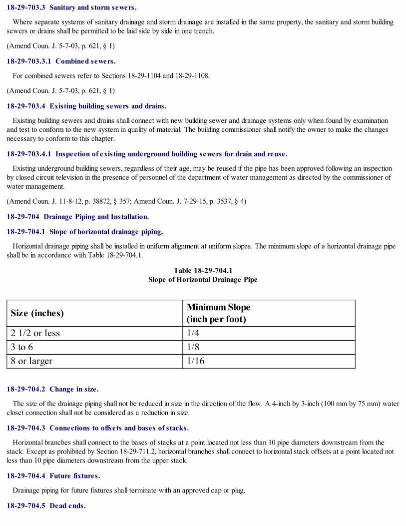
18-29-703.3 Sanitary and storm sewers.
Where separate systems of sanitary drainage and storm drainage are installed in the same property, the sanitary and storm buildingsewers or drains shall be permitted to be laid side by side in one trench.
(Amend Coun. J. 5-7-03, p. 621, § 1)
18-29-703.3.1 Combined sewers.
For combined sewers refer to Sections 18-29-1104 and 18-29-1108.
(Amend Coun. J. 5-7-03, p. 621, § 1)
18-29-703.4 Existing building sewers and drains.
Existing building sewers and drains shall connect with new building sewer and drainage systems only when found by examinationand test to conform to the new system in quality of material. The building commissioner shall notify the owner to make the changesnecessary to conform to this chapter.
18-29-703.4.1 Inspection of existing underground building sewers for drain and reuse.
Existing underground building sewers, regardless of their age, may be reused if the pipe has been approved following an inspectionby closed circuit television in the presence of personnel of the department of water management as directed by the commissioner ofwater management.
(Amend Coun. J. 11-8-12, p. 38872, § 357; Amend Coun. J. 7-29-15, p. 3537, § 4)
18-29-704 Drainage Piping and Installation.
18-29-704.1 Slope of horizontal drainage piping.
Horizontal drainage piping shall be installed in uniform alignment at uniform slopes. The minimum slope of a horizontal drainage pipeshall be in accordance with Table 18-29-704.1.
Table 18-29-704.1Slope of Horizontal Drainage Pipe
Size (inches) Minimum Slope (inch per foot)
2 1/2 or less 1/43 to 6 1/88 or larger 1/16
18-29-704.2 Change in size.
The size of the drainage piping shall not be reduced in size in the direction of the flow. A 4-inch by 3-inch (100 mm by 75 mm) watercloset connection shall not be considered as a reduction in size.
18-29-704.3 Connections to offsets and bases of stacks.
Horizontal branches shall connect to the bases of stacks at a point located not less than 10 pipe diameters downstream from thestack. Except as prohibited by Section 18-29-711.2, horizontal branches shall connect to horizontal stack offsets at a point located notless than 10 pipe diameters downstream from the upper stack.
18-29-704.4 Future fixtures.
Drainage piping for future fixtures shall terminate with an approved cap or plug.
18-29-704.5 Dead ends.

In the installation or removal of any part of a drainage system, dead ends shall be prohibited. Cleanout extensions and approvedfuture fixture drainage piping shall not be considered as dead ends.
18-29-704.5.1 Freezing.
No soil or waste pipe shall be installed or permitted outside of a building or in an exterior wall unless provisions are made to protectsuch piping from freezing. This does not prohibit a soil or waste pipe from extending from a manufactured or mobile home unit to anapproved point of discharge, provided such waste line is protected from freezing.
18-29-704.5.2 Deliberately omitted.
18-29-705 Joints.
18-29-705.1 General.
This section contains provisions applicable to joints specific to sanitary drainage piping.
18-29-705.2 Deliberately omitted.
18-29-705.3 Deliberately omitted.
18-29-705.4 Brass.
Joints between brass pipe or fittings shall comply with Sections 18-29-705.4.1 through 18-29-705.4.4.
18-29-705.4.1 Brazed joints.
All joint surfaces shall be cleaned. An approved flux shall be applied where required. The joint shall be brazed with a filler metalconforming to AWS A5.8.
18-29-705.4.2 Mechanical joints.
Mechanical joints shall be installed in accordance with the manufacturer's instructions.
18-29-705.4.3 Threaded joints.
Threads shall conform to ASME B 120.1. Pipe joint compound or tape shall be applied on the male threads only.
18-29-705.4.4 Welded joints.
All joint surfaces shall be cleaned. The joint shall be welded with an approved filler metal.
18-29-705.5 Cast iron.
Joints between cast-iron pipe or fittings shall comply with Sections 18-29-705.5.1 through 18-29-705.5.3.
18-29-705.5.1 Caulked joints.
Joints for hub and spigot pipe shall be firmly packed with oakum or hemp. Molten lead shall be poured in one operation to a depth ofnot less than 1 inch (25 mm). The lead shall not recede more than 1/8 inch (3 mm) below the rim of the hub and shall be caulked tight.Paint, varnish or other coatings shall not be permitted on the jointing material until after the joint has been tested and approved. Leadshall be run in one pouring and shall be caulked tight. Acid-resistant rope and acid-proof cement shall be permitted.
18-29-705.5.2 Compression gasket joints.
Compression gaskets shall conform to ASTM C 564. Gaskets shall be compressed when the pipe is fully inserted.
18-29-705.5.3 Mechanical joint coupling.
Mechanical joint couplings shall comply with CISPI 310 or ASTM C 1277 and shall meet the requirements of Factory MutualStandard 1680, Class I, with a minimum working pressure of 15 psi (103.4 kPa). The elastomeric sealing sleeve shall conform toASTMC 564 or CSA CAN/CSA-B602 and shall be provided with a center stop. Mechanical joint couplings shall be installed inaccordance with the manufacturer's installation instructions.
18-29-705.6 Concrete joints.
Joints between concrete pipe or fittings shall be made with an elastomeric seal conforming to ASTM C 443, ASTM C 1173, CSA-

A257.3 or CSA CAN/CSA- B602.
18-29-705.7 Copper pipe.
Joints between copper or copper-alloy pipe or fittings shall comply with Sections 18-29-705.7.1 through 18-29-705.7.5.
18-29-705.7.1 Brazed joints.
All joint surfaces shall be cleaned. An approved flux shall be applied where required. The joint shall be brazed with a filler metalconforming to AWS A5.8.
18-29-705.7.2 Mechanical joints.
Mechanical joints shall be installed in accordance with the manufacturer's instructions.
18-29-705.7.3 Soldered joints.
Solder joints shall be made in accordance with the methods of ASTM B 828. All cut tube ends shall be reamed to the full insidediameter of the tube end. All joint surfaces shall be cleaned. A flux conforming to ASTM B 813 shall be applied. The joint shall besoldered with a solder conforming to ASTM B 32.
18-29-705.7.4 Threaded joints.
Threads shall conform to ASME B 120.1. Pipe joint compound or tape shall be applied on the male threads only.
18-29-705.7.5 Welded joints.
All joint surfaces shall be cleaned. The joint shall be welded with an approved filler metal.
18-29-705.8 Copper tubing.
Joints between copper or copper-alloy tubing or fittings shall comply with Sections 18-29-705.8.1 through 18-29-705.8.3.
18-29-705.8.1 Brazed joints.
All joint surfaces shall be cleaned. An approved flux shall be applied where required. The joint shall be brazed with a filler metalconforming to AWS A5.8.
18-29-705.8.2 Mechanical joints.
Mechanical joints shall be installed in accordance with the manufacturer's instructions.
18-29-705.8.3 Soldered joints.
Solder joints shall be made in accordance with the methods of ASTM B 828. All cut tube ends shall be reamed to the full insidediameter of the tube end. All joint surfaces shall be cleaned. A flux conforming to ASTM B 813 shall be applied. The joint shall besoldered with a solder conforming to ASTM B 32.
18-29-705.9 Borosilicate glass joints.
Glass-to-glass connections shall be made with a belted compression-type stainless steel (300 series) coupling with contoured acid-resistant elastomer compression ring and a fluorocarbon polymer inner seal ring or with caulked joints in accordance with Section 18-29-705.9.1.
18-29-705.9.1 Caulked joints.
Every lead-caulked joint for hub and spigot soil pipe shall be firmly packed with oakum or hemp and filled with molten lead not lessthan 1 inch (25 mm) deep and not to extend more than 1/8 inch (3 mm) below the rim of the hub. Paint, varnish or other coatings shallnot be permitted on the jointing material until after the joint has been tested and approved. Lead shall be run in one pouring and shall becaulked tight. Acid-resistant rope and acid-proof cement shall be permitted.
18-29-705.10 Steel.
Joints between galvanized steel pipe or fittings shall comply with Sections 18-29-705.10.1 and 18-29-705.10.2.
18-29-705.10.1 Threaded joints.

Threads shall conform to ASME B 120.1. Pipe joint compound or tape shall be applied on the male threads only.
18-29-705.10.2 Mechanical joints.
Joints shall be made with an approved elastomeric seal. Mechanical joints shall be installed in accordance with the manufacturer'sinstructions.
18-29-705.11 Deliberately omitted.
18-29-705.12 PVC plastic.
Joints between PVC plastic pipe or fittings shall comply with Sections 18-29-705.12.1 through 18-29-705.12.3.
18-29-705.12.1 Mechanical joints.
Mechanical joints on drainage pipe shall be made with an elastomeric seal conforming to ASTM C 1173, ASTM D 3212 or CSACAN/CSA-B602. Mechanical joints shall not be installed in above-ground systems, unless otherwise approved. Joints shall be installedin accordance with the manufacturer's instructions.
18-29-705.12.2 Solvent cementing.
Joint surfaces shall be clean and free from moisture. A purple primer that conforms to ASTM F 656 shall be applied. Solvent cementnot purple in color and conforming to ASTM D 2564, CSA CAN/CSA-B 137.3, CSA CAN/CSA-B 181.2 or CSA CAN/CSA- B182.1shall be applied to all joint surfaces. The joint shall be made while the cement is wet and shall be in accordance with ASTM D 2855.Solvent-cement joints shall be permitted above or below ground.
18-29-705.12.3 Threaded joints.
Threads shall conform to ASME B 1.20.1. Schedule 80 or heavier pipe shall be permitted to be threaded with dies specificallydesigned for plastic pipe. Approved thread lubricant or tape shall be applied on the male threads only.
18-29-705.13 Vitrified clay.
Joints between vitrified clay pipe or fittings shall be made with an elastomeric seal conforming to ASTM C 425, ASTM C 1173 orCSA CAN/CSA-B602.
18-29-705.14 Joints between different materials.
Joints between different piping materials shall be made with a mechanical joint of the compression or mechanical-sealing type, or aspermitted in Sections 18-29-705.14.1 through 18-29-705.14.6. Connectors or adapters shall have an elastomeric seal conforming toASTM C 425, ASTM C 443, ASTM C 564, ASTM C 1173, ASTM D 1869, ASTM F 477, CSA A2573 or CSA CAN/CSA B602.Joints shall be installed in accordance with the manufacturer's instructions.
18-29-705.14.1 Copper or copper-alloy tubing to cast-iron hub pipe.
Joints between copper or copper-alloy tubing and cast-iron hub pipe shall be made with a brass ferrule or compression joint. Thecopper or copper-alloy tubing shall be soldered to the ferrule in an approved manner, and the ferrule shall be joined to the cast-iron hubby a caulked joint or a mechanical no hub coupling.
18-29-705.14.2 Copper or copper-alloy tubing to galvanized steel pipe.
Joints between copper or copper-alloy tubing and galvanized steel pipe shall be made with a brass converter fitting or dielectricfitting. The copper tubing shall be soldered to the fitting in an approved manner, and the fitting shall be screwed to the threaded pipe.
18-29-705.14.3 Cast-iron pipe to galvanized steel or brass pipe.
Joints between cast-iron and galvanized steel or brass pipe shall be made by either caulked or threaded joints or with an approvedadapter fitting.
18-29-705.14.4 Plastic pipe or tubing to other piping material.
Joints between different grades of plastic pipe or between plastic pipe and other piping material shall be made with an approvedadapter fitting. Joints between plastic pipe and cast-iron hub pipe shall be made by a caulked joint or a mechanical compression joint.
18-29-705.14.5 Deliberately omitted.

18-29-705.14.6 Borosilicate glass to other materials.
Joints between glass pipe and other types of materials shall be made with adapters having a TFE seal and shall be installed inaccordance with the manufacturer's instructions.
18-29-705.15 Drainage slip joints.
Slip joints shall be made with an approved elastomeric gasket and shall only be installed on the trap outlet, trap inlet and within thetrap seal. Slip joints installed in concealed locations shall conform to Section 18-29-405.8.
18-29-705.16 Caulking ferrules.
Ferrules shall be of red brass and shall be in accordance with Table 18-29-705.16.
Table 18-29-705.16Caulking Ferrule Specifications
Pipe Sizes(inches)
Inside Diameter(inches)
Length(inches)
Minimum WeightEach
2 2 1/4 4 1/2 1 pound
3 3 1/4 4 1/2 1 pound12 ounces
4 4 1/4 4 1/2 2 pounds6 ounces
For SI: 1 inch = 25.4 mm, 1 ounce = 28.35g, 1 pound = 0.454 kg
18-29-705.17 Deliberately omitted.
18-29-706 Connections Between Drainage Piping And Fixtures.
18-29-706.1 Connections and changes in direction.
All connections and changes in direction of the sanitary drainage system shall be made with approved drainage fittings. Connectionsbetween drainage piping and fixtures shall conform to Section 18-29-405.
18-29-706.2 Obstructions.
The fittings shall not have ledges, shoulders or reductions capable of retarding or obstructing flow in the piping. Threaded drainagepipe fittings shall be of the recessed drainage type.
18-29-706.3 Installation of fittings.
Fittings shall be installed to guide sewage and waste in the direction of flow. Change in direction shall be made by fittings installed inaccordance with Table 18-29-706.3. Change in direction by combination fittings, side inlets or increasers shall be installed inaccordance with Table 18-29-706.3 based on the pattern of flow created by the fitting. Double sanitary tee patterns shall not receivethe discharge of back-to-back water closets and fixtures or appliances with pumping action discharge.
Table 18-29-706.3Fittings for Change in Direction
Type of Fitting PatternChange in DirectionHorizontal tovertical
Vertical tohorizontal
Horizontal tohorizontal
Sixteenth bend X X X

Eighth bend X X XSixth bend X X XQuarter bend X X a X aShort sweep X X a, b X aLong sweep X X XSanitary tee X c - -Wye X X XCombination wye and eightbend X X X
For SI: 1 inch = 25.4 mm.
a The fittings shall only be permitted for a 2-inch or smaller fixture drain.
b Three inches and larger.
c For a limitation on double sanitary tees, see Section 706.3.
18-29-707 Prohibited Joints and Connections.
18-29-707.1 Prohibited joints.
The following types of joints and connections shall be prohibited, unless approved by the department of water management guidelinesor as referenced in the current edition of that department's permit requirement and fees:
1. Cement or concrete joints;
2. Mastic or hot-pour bituminous joints;
3. Joints made with fittings not approved for the specific installation;
4. Joints between different diameter pipes made with elastomeric rolling O-rings;
5. Solvent-cement joints between different types of plastic pipe; and
6. Saddle-type fittings.
(Amend Coun. J. 11-8-12, p. 38872, § 358)
18-29-708 Cleanouts.
18-29-708.1 Scope.
This section shall govern the size, location, installation and maintenance of drainage pipe cleanouts.
18-29-708.2 Cleanout plugs.
Cleanout plugs shall be of brass, plastic or other approved materials. Brass cleanout plugs shall be utilized with metallic drain, wasteand vent piping only, and shall conform to ASTM A 74. Plastic cleanout plugs shall conform to the requirements of Section 18-29-702.4. Plugs shall have raised square or countersunk square heads. Countersunk heads shall be installed where raised heads are a triphazard. Cleanout plugs with borosilicate glass systems shall be of borosilicate glass.
18-29-708.3 Where required.
Cleanouts shall be located in accordance with Sections 18-29-708.3.1 through 18-29-708.3.5.
18-29-708.3.1 Horizontal drains within buildings.
All horizontal drains shall be provided with cleanouts located not more than 100 feet (30.48m) apart, except that the maximum shallbe 50 feet (15.25 m) for drains 4 inches (100 mm) diameter or less, 150 feet (45.7 m) for drains 10 inches (250 mm) diameter or

larger.
18-29-708.3.2 Building sewers.
All building sewers shall be provided with cleanouts located not more than 100 feet (30.48 m) apart measured from the upstreamentrance of the cleanout, unless manholes are adequately spaced according to the current edition of the permit requirement and feesbook.
18-29-708.3.3 Changes of direction.
Cleanouts shall be installed at each change of direction of the building drain or horizontal waste or soil lines greater than 45 degrees(0.79 rad). Where more than one change of direction occurs in a run of piping, only one cleanout shall be required for each 40 feet(12.2 m) of developed length of the drainage piping.
18-29-708.3.4 Base of stack.
A cleanout shall be provided at the base of each waste or soil stack.
18-29-708.3.5 Building drain and building sewer junction.
There shall be a cleanout near the junction of the building drain and the building sewer. The cleanout shall be either inside or outsidethe building wall and shall be brought up to the finished ground level or to the basement floor level. An approved two-way cleanout isallowed to be used at this location to serve as a required cleanout for both the building drain and building sewer. The cleanout at thejunction of the building drain and building sewer shall not be required if the cleanout on a 3-inch (75 mm) or larger diameter soil stack islocated within a developed length of 10 feet (3.05 m) of the building drain and building sewer connection.
18-29-708.3.6 Manholes.
Manholes serving a building drain shall have secured gas-tight covers and shall be located in accordance with Section 18-29-708.8.
18-29-708.4 Concealed piping.
Cleanouts on concealed piping, piping under a floor slab or piping in a crawl space of less than 36 inches (915 mm) in height, orpiping in a plenum shall be extended through and shall terminate flush with the finished wall, floor or ground surface or shall beextended to the outside of the building. Cleanout plugs shall not be covered with cement, plaster or any other permanent finish material.Where it is necessary to conceal a cleanout or to terminate a cleanout in an area subject to vehicular traffic, the covering plate, accessdoor or cleanout shall be of an approved type designed and installed for this purpose.
18-29-708.5 Opening direction.
Every cleanout shall be installed to open to allow cleaning in the direction of the flow of the drainage pipe or at right angles thereto.
18-29-708.6 Prohibited installation.
Cleanout openings shall not be utilized for the installation of new fixtures or floor drains, except where approved and where anothercleanout of equal access and capacity is provided.
18-29-708.7 Minimum size.
Cleanouts shall be the same nominal size as the pipe they serve up to 4 inches (100 mm). For pipes larger than 4 inches (100 mm)nominal size, the minimum size of the cleanout shall be 4 inches (100 mm).
Exception: "P" trap connections with slip joints or ground joint connections, or stack cleanouts that are no more than one pipediameter smaller than the drain served, shall be approved.
18-29-708.8 Pipes 8 inches and larger.
For building sewers 8 inches (200 mm) and larger nominal size, manholes shall be provided and located at each change in directiongreater than 45 degrees, and at the locations and intervals referenced in the current edition of the permit requirement and fees book.
18-29-708.9 Clearances.
Cleanouts on 6-inch (150 mm) and smaller pipes shall be provided with a clearance of not less than 18 inches (457 mm) for rodding.Cleanouts on 8-inch (200 mm) and larger pipes shall be provided with a clearance of not less than 36 inches (914 mm) for rodding.

18-29-708.10 Access.
Access shall be provided to all cleanouts.
18-29-709 Fixture Units.
18-29-709.1 Values for fixtures.
Drainage fixture unit values as given in Table 18-29-709.1 designate the relative load weight of different kinds of fixtures that shallbe employed in estimating the total load carried by a soil or waste pipe, and shall be used in connection with Tables 18-29-710A and18-29-710B of sizes for soil, waste and vent pipes for which the permissible load is given in terms of fixture units.
Table 18-29-709.1Drainage Fixture Units for Fixtures and Groups
Fixture TypeDrainage FixtureUnit Value asLoad Factors
Minimum Size ofTrap (inches)
Automatic clothes washers, commercial a 3 2Automatic clothes washers, residential 2 2Bathroom group consisting of water closet,lavatory, bidet and bathtub or shower 6 -
Bathroom b (with or without overheadshower or whirlpool attachments) 2 1 1/2
Bidet 2 1 1/4Combination sink and tray 2 1 1/2Dental lavatory 1 1 1/4Dental unit or cuspidor 1 1 1/4Dishwashing machine, c domestic 2 1 1/2Drinking fountains 1/2 1 1/4Emergency floor drain 0 2Floor drains 2 2Kitchen sink, domestic 2 1 1/2Kitchen sink, domestic with food wastegrinder and/or dishwasher 2 1 1/2
Laundry tray (1 or 2 compartments) 2 1 1/2Lavatory 1 1 1/4Shower compartment, domestic 2 2Sink 2 1 1/2Urinal 4 Footnote dUrinal, 1 gallon per flush or less 2 e Footnote dWash sink, (circular or multiple) each set offaucets 2 1 1/2
Water closet, flushometer tank, public or 4 e Footnote d

privateWater closet private installation 4 Footnote dWater closet public installation 6 Footnote d
For SI: 1 inch = 25.4 mm, 1 gallon = 3.785L.
a For traps larger than 3 inches, use Table 709.2.
b A showerhead over a bathtub or whirlpool bathtub attachments does not increase the drainage fixture unit value.
c See Section 709.2 for methods of computing unit value of fixtures not listed in Table 709.1 or for rating of devices with intermittentflows.
d Trap size shall be consistent with the fixture outlet size.
e For the purpose of computing loads on building drains and sewers, water closets or urinals shall not be rated at a lower drainagefixture unit unless the lower values are confirmed by testing.
18-29-709.2 Fixtures not listed in Table 18-29-709.1.
Fixtures not listed in Table 18-29-709.1 shall have a drainage fixture unit load based on the outlet size of the fixture in accordancewith Table 18-29-709.2. The minimum trap size for unlisted fixtures shall be the size of the drainage outlet but not less than 1 1/4inches (32 mm).
Table 18-29-709.2Drainage Fixture Units for Fixture Drains or Traps
Fixture Drain or Trap Size (inches) Drainage Fixture Unit Value1 1/4 11 1/2 22 32 1/2 43 54 6
For SI: 1 inch = 25.4 mm.
18-29-709.3 Values for continuous flow.
Drainage fixture unit values for continuous flow into a drainage system shall be computed on the basis that 1 gallon per minute (0.06L/s) of flow is equivalent to one fixture unit.
18-29-709.4 Deliberately omitted.
18-29-709.5 Values for indirect waste receptor.
The drainage fixture unit load of an indirect waste receptor receiving the discharge of indirectly connected fixtures shall be the sumof the drainage fixture unit values of the fixtures that discharge to the receptor. If this drainage fixture value is less than the indirectwaste receptor drainage fixture value given in Table 18-29-709.1 or Table 18-29-709.2, then the values in the referenced tables shallbe used.
18-29-710 Drainage System Sizing.
18-29-710.1 Maximum fixture unit load.

The maximum number of drainage fixture units connected to a given size of building sewer, building drain or horizontal branch of thebuilding drain shall be determined using Table 18-29-710A. The maximum number of drainage fixture units connected to a given size ofhorizontal branch or vertical soil or waste stack shall be determined using Table 18-29-710B.
18-29-710.1.1 Maximum fixture units.
The maximum number of fixture units that may be connected to a given size of house drain, horizontal branch, or vertical soil orwaste stack is given in Tables 18-29-710A and 18-29-710B. Storm and combined house drains and house sewers shall comply withSections 18-29-1106 and 18-29-1108 of this chapter.
18-29-710.1.2 Minimum size.
The minimum required pipe size for water closets or pedestal urinal branches and stacks shall be 4 inches (100 mm) except that anybuilding three stories or less in height and used exclusively for family unit occupancy, may utilize a 3-inch (75 mm) soil stack when notexceeding 30 fixture units, with not more than two water closets per floor or two water closets per horizontal branch. The wasteconnection to any water closet shall be provided with an approved 4-inch (100 mm) closet flange. The minimum required sizes forunderground branches from downspouts, floor drains, laundry trays and sink stacks shall be 3 inches (75 mm). (See Tables 18-29-710A and 18-29-710B.)
18-29-710.1.3 Horizontal stack offsets.
Horizontal stack offsets shall be sized as required for building drains in accordance with Table 18-29-710A, except as required bySection 18-29-711.4.
18-29-710.1.4 Vertical stack offsets.
Vertical stack offsets shall be sized as required for straight stacks in accordance with Table 18-29-710B, except when required to besized as a building drain in accordance with Section 18-29-711.1.
18-29-710.2 Future fixtures.
When provision is made for the future installation of fixtures, those provided for shall be considered in determining the required sizesof drain pipes. Construction to provide for such future installation shall be terminated with an approved cap or plug.
18-29-710.3 Underground drainage piping.
Any portion of the drainage system installed underground or below a basement or cellar shall not be less than 4 inches (100 mm) indiameter.
Table 18-29-710ABuilding Drains and Sewers
Diameter of Pipe(inches)
Maximum Number of Drainage Fixture Units Connectedto any Portion of the Building Drain or the BuildingSewer, Including Branches of the Building Drain aSlope per Foot1/6 inch 1/8 inch 1/4 inch 1/2 inch
1 1/4 - - 1 11 1/2 - - 3 32 - - 21 262 1/2 - - 24 313 - 36 42 504 - 180 216 2505 - 390 480 575

6 - 700 840 1,0008 1,400 1,600 1,920 2,30010 2,500 2,900 3,500 4,20012 2,900 4,600 5,600 6,70015 7,000 8,300 10,000 12,000
For SI: 1 inch = 25.4 mm, 1 inch per foot = 0.0833 mm/m.
a The minimum size of any building drain serving a water closet shall be 3 inches.
Table 18-29-710BHorizontal Fixture Branches and Stacks a
Diameter of Pipe(inches)
AnyHorizontalFixtureBranch
Maximum Number of Fixture Units that may beConnected to:One Stack of 3Stories inHeight or 3Intervals
More than 3 Stories in Height
Total forStack
Total at OneStory or BranchInterval
1 1/2 3 4 8 22 6 10 24 62 1/2 12 20 42 93 20 30 60 164 160 240 500 905 360 540 1,100 2006 620 960 1,900 3508 1,400 2,200 3,600 60010 2,500 3,800 5,600 1,00012 3,900 6,000 8,400 1,50015 7,000 - - -
For SI: 1 inch = 25.4 mm.
a Does not include branches of house drain.
18-29-711 Offsets in Drainage Piping in Buildings of Five Stories or More.
18-29-711.1 Horizontal branch connections above or below vertical stack offsets.
If a horizontal branch connects to the stack within 2 feet (610 mm) above or below a vertical stack offset, and the offset is locatedmore than four branch intervals below the top of the stack, the offset shall be vented in accordance with Section 18-29-915.
18-29-711.1.1 Omission of vents for vertical stack offsets.
Vents for vertical offsets required by Section 18-29-711.1 shall not be required where the stack and its offset are sized as a buildingdrain (see Table 18-29-710A, Column 5).

18-29-711.2 Horizontal branch connections to horizontal stack offsets.
When a horizontal stack offset is located more than four branch intervals below the top of the stack, a horizontal branch shall notconnect within the horizontal stack offset or within 2 feet (610 mm) above or below such offset.
18-29-711.3 Horizontal stack offsets.
A stack with a horizontal offset located more than four branch intervals below the top of the stack shall be vented in accordancewith Section 914 and sized as follows:
1. The portion of the stack above the offset shall be sized as for a vertical stack based on the total number of drainage fixture unitsabove the offset.
2. The offset shall be sized in accordance with Section 18-29-710.1.1.
3. The portion of the stack below the offset shall be sized as for the offset or based on the total number of drainage fixture units onthe entire stack, whichever is larger (see Table 18-29-710B, Column 4).
18-29-711.3.1 Omission of vents for horizontal stack offsets.
Vents for horizontal stack offsets required by Section 18-29-711.3 shall not be required where the stack and its offset is one pipesize larger than required for a building drain (see Table 18-29-710A, Column 5) and the entire stack and offset is not less in cross-sectional area than that required for a straight stack plus the area of an offset vent as provided for in Section 18-29-915. Omission ofoffset vents in accordance with this section shall not constitute approval of horizontal branch connections within the offset or within 2feet (610 mm) above or below the offset.
18-29-711.3.2 Suds pressure zones.
Drainage stacks that receive wastes from sinks, automatic dishwashers, laundry trays, laundry washing machines, and similarfixtures shall have the drainage and vent piping so arranged that suds pressures will not affect fixtures in the lower portion of thedrainage system. No fixture drain, branch, or branch vent shall connect to any stack in a suds pressure zone. Such zones shall beconsidered to exist at any offset of 60 degrees to 90 degrees or at the base of any drainage.
18-29-711.3.2.1 Height.
When the drainage portion of a stack exceeds 16 feet (4.88 m) in height above a 45-degree to 90-degree offset or house drain, itshall have its lower portion consisting of 30 percent of its height from such offset free of any fixture drain or branch. Such sudspressure zone of the drainage stack need not exceed 24 feet (7.32 m) in height.
18-29-711.3.2.2 Upstream.
In an offset of 60 degrees to 90 degrees or a house drain when the drainage portion of a stack exceeds 16 feet (4.88 m) in height, azone in the horizontal piping consisting of 30 percent upstream of the drainage stack connection shall be free of any drainage openings.Such suds pressure zone of the offset or house drain need not exceed 24 feet (7.32 m).
18-29-711.3.2.3 Downstream.
In an offset of 60 degrees to 90 degrees or a house drain when the drainage portion of a stack exceeds 16 feet (4.88 m) in height, azone in the horizontal piping consisting of 15 percent downstream of the drainage stack connection shall be free of any drainageopenings. Such suds pressure zone of the offset or house drain need not exceed 12 feet (3.66 m).
18-29-711.4 Offsets below lowest branch.
Where a vertical offset occurs in a soil or waste stack below the lowest horizontal branch, change in diameter of the stack becauseof the offset shall not be required. If a horizontal offset occurs in a soil or waste stack below the lowest horizontal branch, the requireddiameter of the offset and the stack below it shall be determined as for a building drain in accordance with Table 18-29-710A.
18-29-712 Sumps and Ejectors.
18-29-712.1 Building drains below sewer.
Building drains that cannot be discharged to the sewer by gravity flow shall be discharged into a tightly covered and vented sump,from which stack the liquid shall be lifted and discharged into the building gravity drainage system by automatic pumping equipment orother approved method.

18-29-712.2 Check and gate valve required.
A gate valve located on the discharge side of the check valve shall be installed in the pump or ejector discharge piping between thepump or ejector and the gravity drainage system. Access shall be provided to such valves. Such valves shall be located above thesump cover required by Section 18-29-712.1 or, when the discharge pipe from the ejector is below grade, the valves shall be accessiblylocated outside the sump below grade in an access pit with a removable access cover.
Exception: In single family residential buildings, only a check valve shall be required, located on the discharge piping from thesewage pump or ejector.
18-29-712.3 Sump design.
The sump pump, pit and discharge piping shall conform to the requirements of Sections 18-29-712.3.1 through 18-29-712.3.5.
18-29-712.3.1 Sump pump.
The sump pump capacity and head shall be appropriate to anticipated use requirements.
18-29-712.3.2 Sump pit.
The sump pit shall be not less than 18 inches (457 mm) in diameter and 30 inches (762 mm) deep, unless otherwise approved. Thepit shall be accessible and located such that all drainage flows into the pit by gravity. An approved sump pit or tank within a buildingreceiving the discharge from sanitary drains shall be constructed of approved fiberglass, steel, cast iron, reinforced concrete pipe orother approved materials. Approved plastic or fiberglass liners may be used in conjunction with any of the approved materialsreferenced above. The pit bottom shall be solid and provide permanent support for the pump. The sump pit shall be fitted with a gas-tight removable cover adequate to support anticipated loads in the area of use. The sump pit receiving sanitary flow shall be vented inaccordance with Article 18-29-9.
(Amend Coun. J. 3-27-02, p. 82090, § 3; Amend Coun. J. 7-29-15, p. 3537, § 4)
18-29-712.3.3 Discharge piping.
Discharge piping shall meet the requirements of Section 18-29-712.2.
18-29-712.3.4 Maximum effluent level.
The effluent level control shall be adjusted and maintained to at all times prevent the effluent in the sump from rising to within 2inches (50 mm) of the invert of the gravity drain inlet into the sump.
18-29-712.3.5 Ejector connection to the drainage system.
Pumps connected to the drainage system shall connect to the building sewer or shall connect to a wye fitting in the building drain aminimum of 10 feet (3.05 mm) from the base of any soil stack, waste stack or fixture drain. Where the discharge line connects intohorizontal drainage piping, the connector shall be made through a wye fitting into the top of the drainage piping.
18-29-712.4 Sewage pumps and sewage ejectors.
A sewage pump or sewage ejector shall automatically discharge the contents of the sump to the building drainage system.
18-29-712.4.1 Capacity.
A sewage pump or sewage ejector shall have the capacity and head for the application requirements. Pumps or ejectors that receivethe discharge of water closets shall be capable of handling spherical solids with a diameter of up to and including 2 inches (50 mm).Other pumps or ejectors shall be capable of handling spherical solids with a diameter of up to and including 1 inch (25 mm). Theminimum capacity of a pump or ejector based on the diameter of the discharge pipe shall be in accordance with Table 18-29-712.4.1.
Exception: Grinder pumps or grinder ejectors that receive the discharge of water closets shall have a minimum discharge openingof 1 1/4 inches (32 mm).
Table 18-29-712.4.1Minimum Capacity of Sewage Pump or Sewage Ejector
Diameter of the Discharge Pipe (inches) Capacity of Pump or Ejector (gpm)

2 212 1/2 303 46
For SI: 1 inch = 25.4 mm, 1 gpm = 3.785 L/m.
18-29-712.4.2 Duplex equipment required.
Where six or more water closets are connected to a sewage ejector, the system shall incorporate duplex pumping equipment.
18-29-713 Health Care Plumbing.
18-29-713.1 Scope.
Sections 18-29-713.1 through 18-29-713.11.4 shall govern those aspects of health care plumbing systems that differ from plumbingsystems in other structures. Health care plumbing systems shall conform to these sections in addition to the other requirements of thischapter. These sections shall apply to the special devices and equipment installed and maintained in the following occupancies: nursinghomes, homes for the aged, orphanages, infirmaries, first aid stations, psychiatric facilities, clinics, professional offices of dentists anddoctors, mortuaries, educational facilities, surgery, dentistry, research and testing laboratories, establishments manufacturingpharmaceutical drugs and medicines, and other structures with similar apparatus and equipment classified as plumbing.
18-29-713.2 Bedpan washers and clinical sinks.
Bedpan washers and clinical sinks shall connect to the drainage and vent system in accordance with the requirements for a watercloset. Bedpan washers shall also connect to a local vent.
18-29-713.3 Indirect waste.
All sterilizers, steamers and condensers shall discharge to the drainage through an indirect waste pipe by means of an air gap.Where a battery of not more than three sterilizers discharges to an individual receptor, the distance between the receptor and asterilizer shall not exceed 8 feet (2438 mm). The indirect waste pipe on a bedpan steamer shall be trapped.
18-29-713.4 Vacuum system station.
Ready access shall be provided to vacuum system station receptacles. Such receptacles shall be built into cabinets or recesses andshall be visible.
18-29-713.5 Bottle system.
Vacuum (fluid motion) systems intended for collection, moving and disposing of blood, pus or other fluids by the bottle system shallbe provided with receptacles equipped with an overflow prevention device at each vacuum outlet station.
18-29-713.6 Central disposal system equipment.
All central vacuum (fluid suction) systems shall provide continuous service systems equipped with collecting or control tanks shallprovide for draining and cleaning of the tanks while the system is in operation. In hospitals, the system shall be connected to theemergency power system. The exhausts from a vacuum pump serving a vacuum (fluid suction) system shall discharge separately toopen air above the roof.
18-29-713.7 Central vacuum or disposal systems.
Where the waste from a central vacuum (fluid suction) system of the barometric-lag, collection-tank or bottle-disposal type isconnected to the drainage system, the waste shall be directly connected to the sanitary drainage system through a trapped waste.
18-29-713.7.1 Piping.
The piping of a central vacuum (fluid suction) system shall be of corrosion-resistant material with a smooth interior surface. Abranch shall not be less than 1/2 inch (12 mm) nominal pipe size for one outlet and shall be sized in accordance with the number ofvacuum outlets. A main shall not be less than 1 inch (25 mm) nominal pipe size. The pipe sizing shall be increased in accordance withthe manufacturer's instructions as stations are increased. For the purposes of inspection, maintenance and replacement, all piping shallhave cleanout facilities on mains and branches. Access shall be provided to such cleanout facilities.

18-29-713.7.2 Velocity.
The velocity of airflow in a central vacuum (fluid suction) system shall be less than 5,000 feet per minute (25.4 m/s).
18-29-713.8 Vent connections prohibited.
Connections between local vents serving bedpan washers or sterilizer vents serving sterilizing apparatus and normal sanitaryplumbing systems are prohibited. Only one type of apparatus shall be served by a local vent.
18-29-713.9 Local vents and stacks for bedpan washers.
Bedpan washers shall be vented to open air above the roof by means of one or more local vents. The local vent for a bedpan washershall not be less than a 2-inch-diameter (50 mm) pipe. A local vent serving a single bedpan washer is permitted to drain to the fixtureserved.
18-29-713.9.1 Multiple installations.
Where bedpan washers are located above each other on more than one floor, a local vent stack is permitted to be installed to receivethe local vent on the various floors. Not more than three bedpan washers shall be connected to a 2-inch (50 mm) local vent stack, notmore than six to a 3-inch (75 mm) local vent stack and not more than twelve to a 4-inch (100 mm) local vent stack. In multipleinstallations, the connections between a bedpan washer local vent and a local vent stack shall be made with tee or tee-wye sanitarypattern drainage fittings installed in an upright position.
(Amend Coun. J. 11-8-12, p. 38872, § 259)
18-29-713.9.2 Trap required.
The bottom of the local vent stack, except where serving only one bedpan washer, shall be drained by means of a trapped andvented waste connection to the sanitary drainage system. The trap and waste shall be the same size as the local vent stack.
18-29-713.9.3 Trap seal maintenance.
A water supply pipe not less than 1/4 inch (6 mm) in diameter shall be taken from the flush supply of each bedpan washer on thedischarge or fixture side of the vacuum breaker, shall be trapped to form not less than a 3-inch (75 mm) water seal, and shall beconnected to the local vent stack on each floor. The water supply shall be installed so as to provide a supply of water to the local ventstack for cleansing and drain trap seal maintenance each time a bedpan washer is flushed.
18-29-713.10 Sterilizer vents and stacks.
Multiple installations of pressure and non-pressure sterilizers shall have the vent connections to the sterilizer vent stack made bymeans of inverted wye fittings. Access shall be provided to vent connections for the purpose of inspection and maintenance.
18-29-713.10.1 Drainage.
The connection between sterilizer vent or exhaust openings and the sterilizer vent stack shall be designed and installed to drain to thefunnel or basket-type waste fitting. In multiple installations, the sterilizer vent stack shall be drained separately to the lowest sterilizerfunnel or basket-type waste fitting or receptor.
18-29-713.11 Sterilizer vent stack sizes.
Sterilizer vent stack sizes shall comply with Section 18-29-713.11.1 through Section 18-29-713.11.4.
18-29-713.11.1 Bedpan steamers.
The minimum size of a sterilizer vent serving a bedpan steamer shall be 1 1/2 inches (38 mm) in diameter. Multiple installations shallbe sized in accordance with Table 18-29-713.11.1.
Table 18-29-713.11.1Stack Sizes for Bedpan Steamers and Boiling Type Sterilizers (Number of Connections of Various
Sizes Permitted to Various-Sized Sterilizer Vent Stacks)
Stack Size (inches)Connection Size
1 1/2" 2"

1 1/2 a 1 or 02 a 2 or 12 b 1 or 13 a 4 or 23 b 2 or 24 a 8 or 44 b 4 or 4
For SI: 1 inch = 25.4 mm
a Total of each size.
b Combination of sizes.
18-29-713.11.2 Boiling-type sterilizers.
The minimum size of a sterilizer vent stack shall be 2 inches (51 mm) in diameter where serving a utensil sterilizer and 1 1/2 inches(38 mm) in diameter where serving an instrument sterilizer. Combinations of boiling-type sterilizer vent connections shall be sized inaccordance with Table 18-29-713.11.1.
18-29-713.11.3 Pressure sterilizers.
Pressure sterilizer vent stacks shall be 2 1/2 inches (64 mm) minimum. Those serving combinations of pressure sterilizer exhaustconnections shall be sized in accordance with Table 18-29-713.11.3.
Table 18-29-713.11.3Stacks Sizes for Pressure Sterilizers (Number of Connections of Various
Sizes Permitted to Various- Sized Vent Stacks)
Stack Size (inches)Connection Size3/4" 1" 1 1/4" 1 1/2"
1 1/2 a 3 or 2 or 1 -1 1/2 b 2 and 1 - -2 a 6 or 3 or 2 or 12 b 3 and 2 - -2 b 2 and 1 and 1 -2 b 1 and 1 and - 13 a 15 or 7 or 5 or 3
3 b 1 and 1 and 5 and 2 and 2 1
For SI: 1 inch = 25.4 mm
a Total of each size.
b Combination of sizes.
18-29-713.11.4 Pressure instrument washer sterilizer sizes.

The minimum diameter of a sterilizer vent stack serving an instrument washer sterilizer shall be 2 inches (50 mm). Not more thantwo sterilizers shall be installed on a 2-inch (50 mm) stack, and not more than four sterilizers shall be installed on a 3-inch (75 mm)stack.
18-29-714 Deliberately omitted.
18-29-715 Backwater Valves.
18-29-715.1 Sewage backflow.
A backwater valve shall be installed only for plumbing fixtures where the overflow rim of the lowest plumbing fixtures are below thenext upstream manhole in the public sewer. Plumbing fixtures with flood rims above the next upstream manhole shall not dischargethrough the backwater valve.
18-29-715.2 Fixture branches.
Backwater valves shall be installed in the branch of the building drain that receives only the discharge from fixtures located withinsuch branch and shall be located below ground.
18-29-715.3 Material.
All bearing parts of backwater valves shall be of corrosion-resistant material. Backwater valves shall comply with ASMEA112.14.1, CSA CAN/CSA-B 181.1 or CSA CAN/CSA-B 181.2.
18-29-715.4 Seal.
Backwater valves shall be so constructed as to provide a mechanical seal against backflow.
18-29-715.5 Diameter.
Backwater valves, when fully opened, shall have a capacity not less than that of the pipes in which they are installed.
18-29-715.6 Location.
Backwater valves shall be installed so that access is provided to the working parts for service and repair.
18-29-716 Flood Control.
18-29-716.1 Flood control devices.
Flood control devices in any house drain shall be vented and sized in accordance with this chapter. The total fixture units and anycontinuous or semicontinuous flow shall determine the size of the vent. No vent shall be less than 2 inches (50 mm) in diameter.
18-29-716.2 Flood control systems.
Flood control systems may be installed as necessary with the approval of the commissioner of water management. Ground floorplumbing fixtures may discharge into the building sewage ejector, in areas experiencing sewer backup only when all downspouts orother storm drainage is discharging downstream of the backwater valve or when the downspouts are not connected to the sewersystem.
(Amend Coun. J. 11-8-12, p. 38872, § 360)
Article 8. Indirect/Special Waste (18-29-801 et seq.)
18-29-801 General.
18-29-801.1 Scope.
This article shall govern matters concerning indirect waste piping and special wastes. This article shall further control mattersconcerning food handling establishments, sterilizers, clear-water wastes, swimming pools, methods of providing air breaks or air gaps,and neutralizing devices for corrosive wastes.
18-29-801.2 Protection.
All devices, appurtenances, appliances and apparatus intended to serve some special function, such as sterilization, distillation,processing, cooling, or storage of ice or foods, and that discharge to the drainage system, shall be provided with protection against

backflow, flooding, fouling, contamination and stoppage of the drain.
18-29-802 Indirect Wastes.
18-29-802.1 Where required.
Indirect sanitary wastes shall be installed as follows: Waste piping from filters, refrigerators, ice boxes, steam tables, egg boilers,coffee makers, bottleholders, ice cube containers, or any equipment or other receptacle where food or drink is stored shall discharge tothe drainage piping system through an air gap into a waste receptor. The minimum size shall be 1 inch (25 mm) and the maximumlength of the indirect waste shall not exceed 15 feet (4.57 m) and shall be provided with cleanouts at every 90 degree turn and shall beaccessibly located. Indirect wastes shall be piped to the waste receptor with material that is required by this chapter. Waste receptorsserving indirect pipes connected to equipment shall not be installed in any toilet room, closet, store room or any inaccessible space.Each waste receptor shall be trapped and vented as required by this chapter. The air gap shall not be less than 1 inch.
18-29-802.1.1 Deliberately omitted.
18-29-802.1.2 Deliberately omitted.
18-29-802.1.3 Potable clear-water waste.
Where devices and equipment, such as sterilizers, swimming pools and relief valves, discharge potable water to the building drainagesystem, the discharge shall be through an indirect waste pipe by means of an air gap.
18-29-802.1.4 Nonpotable clear-water waste.
Where devices and equipment, such as safe pans, drip pans, process tanks, filters, drips and boilers, discharge nonpotable water tothe building drainage system, the discharge shall be through an indirect waste pipe by means of an air break or an air gap.
18-29-802.1.5 Waste piping.
Waste piping from aspirators, sterilizers or any other equipment which would produce a partial vacuum by cooling shall discharge tothe drainage piping system through an air gap into a waste receptor. The minimum size shall be 1 inch (25 mm) and the maximumlength of the indirect waste shall not exceed 15 feet (4.57 m) and shall be provided with cleanouts at every 90 degree turn which areaccessibly located. Each indirect waste pipe shall be individually piped to the waste receptor with material that is required by thischapter. Waste receptors serving indirect pipes connected to the above equipment shall be located in the same room. Each wastereceptor shall be trapped and vented as required by this chapter. The air gap shall be not less than two times the diameter of theindirect waste pipe.
18-29-802.1.6 Dishwashing machine.
Dishwashing machines shall be indirectly connected, except when located adjacent to a floor drain, whereby the waste may beconnected directly on the sewer side of the floor drain trap, and the fixture shall be trapped and vented as required by this chapter;provided, however, that no other waste or soil drainage line be permitted between the floor drain waste connection and the fixturedrain. All indirectly connected dishwashing machine wastes shall be provided with a vented trap located as close as possible to thedishwashing machine and in the same room. The air gap shall not be less than 1 inch (25 mm).
18-29-802.1.7 Sinks.
Commercial dishwashing sinks, pot washing sinks, pre-rinse sinks, silverware sinks, bar sinks, soda fountain sinks, and other similarfixtures shall be indirectly connected except when located adjacent to a floor drain, whereby the waste may be connected directly onthe sewer side of the floor drain trap, and the fixture shall be trapped and vented as required by this chapter; provided, however, thatno other drainage line be permitted between the floor drain waste connection and the fixture drain. All indirectly connected sinks shallbe provided with a vented trap located as close as possible to the sink and in the same room. The piping from the equipment to the airgap shall not exceed 5 feet (1,525 mm) and shall be of material as required by this chapter. The air gap shall be a minimum of 1 inch(25 mm).
18-29-802.2 Deliberately omitted.
18-29-802.3 Waste receptors.
Every waste receptor shall be of an approved type.
18-29-802.3.1 Open hub waste receptors.

Waste receptors shall be permitted in the form of a hub or pipe extending not less than 1 inch (25 mm) above a water-imperviousfloor and are not required to have a strainer.
18-29-802.4 Standpipes.
Standpipes shall be individually trapped. Standpipes shall extend a minimum of 18 inches (457 mm) and a maximum of 42 inches(1,066 mm) above the trap. Access shall be provided to all standpipe and drains for rodding.
18-29-803 Special Wastes.
18-29-803.1 Deliberately omitted.
18-29-803.2 Neutralizing device required for corrosive wastes.
Corrosive liquids, spent acids or other harmful chemicals that destroy or injure a drain, sewer, soil or waste pipe, or create noxious ortoxic fumes or interfere with sewage treatment processes, shall not be discharged into the plumbing system device for corrosivewaste. No corrosive wastes which are equal or greater in corrosive action than a ph lower than 4.5 or higher than 10.0, havingcorrosive properties sufficient to cause damage or hazards to structures, equipment, or personnel, shall discharge into any house sewerwithout first discharging into a dilution tank or basin. Such devices shall be automatically provided with a sufficient supply of dilutingwater or neutralizing medium so as to make the contents noninjurious before discharge into the drainage system. No other waste pipeshall connect to a dilution basin. Every dilution tank used for this purpose shall be constructed of earthenware, polyethylene, propyleneor glass and shall be provided with a standing waste and overflow or other approved means to insure dilution.
(Amend Coun. J. 3-27-02, p. 82090, § 3)
18-29-803.3 System design.
A chemical drainage vent system shall be designed and installed in accordance with this chapter. Chemical drainage and ventsystems shall be completely separated from the sanitary systems. Chemical waste shall not discharge to a sanitary drainage systemuntil such waste has been treated in accordance with Section 18-29-803.2.
18-29-803.4 Volatile wastes.
Gasoline, benzene, naphtha, and other volatile, flammable or explosive wastes shall not discharge into a house sewer, public sewer,or sewage treatment plant. Refer to Sections 18-29-1003.1 through 1003.13, Interceptors and Separators for oil interceptorrequirements.
18-29-804 Materials, Joints and Connections.
18-29-804.1 General.
The materials and methods utilized for the construction and installation of indirect waste pipes and systems shall comply with theapplicable provisions of Article 7.
18-29-804.2 Acid waste piping material.
Material for acid drainage waste and vents in Article 7 shall be specifically indicated and approved for acid waste drainage.
18-29-805 Waste Water Control.
18-29-805.1 Preliminary treatment.
Whenever an industrial plant or other establishment discharges or proposes to discharge industrial wastes into any waters, sewer,drain, watercourse or natural outlet in the city of Chicago, such plant or establishment shall either:
1. Reduce or modify the objectionable characteristics or constituents of such industrial wastes to meet the limits or requirements ofSection 18-29-805.2 and to prevent pollution; or
2. Control the quantities and rates of discharge of such industrial wastes over a 24-hour day and a seven- day week to preventsurge discharges which may place an unreasonable burden upon the sewage works on the metropolitan water reclamation district.
18-29-805.1.1 Approval.
The commissioner of water management shall require the owner, operator or tenant of such industrial plant or establishment toprovide adequate preliminary treatment or handling facilities to accomplish such a result. Before any permit for the construction of

preliminary treatment or handling facilities is issued, plans, specifications and other pertinent data or information relating to suchproposed treatment or handling facilities shall be submitted for the approval of said commissioner. No permit shall be issued and noconstruction of such facilities shall be commenced without the prior written approval of said commissioner; and no substantial alterationor addition to or in the sewer or drain or in the preliminary treatment or handling facilities shall be made without the prior writtenapproval of said commissioner.
(Amend Coun. J. 11-8-12, p. 38872, § 361)
18-29-805.2 Prohibited wastes.
No person shall discharge or cause to be discharged any of the wastes or waters described in Sections 18-29-805.2.1 and 18-29-805.2.2 into any sewer, watercourse, natural outlet or waters within or partially within or adjoining the boundaries of the city ofChicago.
18-29-805.2.1 Maximum concentration.
Maximum concentration acceptable for discharge into the sewage system of the city of Chicago shall be in accordance with that setforth by the metropolitan water reclamation district ordinance titled the sewage and waste control ordinance enacted September 18,1969 and as amended from time to time.
18-29-805.2.2 Types of discharge.
Any discharge of wastes or water into a sewer which terminates in or is a part of the sewage system of the city of Chicago mustnot contain the following:
1. Water or wastes containing more than 100 parts per million (833 pounds per million gallons; 378 kg. per 3,785,400 L) of fats, oilsor greases if such water or wastes are in the opinion of the commissioner of water management sufficient to:
1. Interfere with the biological process of a sewage treatment plant;
2. Interfere with proper operation of the sewage works; or
3. Cause obstruction to flow in sewers; or cause pollution as herein defined;
2. Liquids, solids or gases which by reason of their nature or quantity are sufficient to cause fire or explosion or be injurious in anyway to the structures making up the sewage works or to the operation of the sewage works;
3. Noxious or malodorous liquids, gases or substances which whether singly or by interactions with other wastes are sufficient tocreate a public nuisance or hazard to life sufficient to prevent entry into the sewers for their maintenance and repair;
4. Water or wastes containing toxic substances in quantities which are sufficient to pose a hazard to life or interfere with thebiological processes of the sewage treatment works;
5. Garbage that has not been ground or comminuted to such a degree that all particles will be carried freely in suspension underconditions normally prevailing in public sewers with no particle greater than 1/2 inch (13 mm) in dimension;
6. Radioactive wastes unless they comply with the Atomic Energy Commission Act of 1954 (68 Stat. 919 as amended and Part 20Subpart D - Waste Disposal, Section 20.303 of the regulations issued by the Atomic Energy Commission) or amendments thereto;
7. Solid or viscous wastes which cause obstruction to flow in sewers or other interference with the proper operation of the sewagesystem or sewage treatment works, such as grease, uncomminuted garbage, animal guts or tissues, paunch manure, bone, hair, hides,fleshings, entrails, feathers, sand, cinders, ashes, spent lime, stone or marble dust, metal, glass, straw, shavings, grass clippings, rags,spent grain, waste paper, wood, plastic, gas, tar, asphalt, residues, residues from refining processing of fuels or lubricating oil, gasoline,naptha and similar substances;
8. Liquids or vapors having a temperature higher than 150°F (65.7°C) at point of entrance into a public sewer;
9. Waters or waste containing substances which are not amenable to treatment or reduction by the sewage treatment processemployed or are amenable to treatment only to such degree that the water reclamation plants effluent cannot meet the requirement ofother agencies having jurisdiction of discharge to the receiving waters;
10. Excessive discoloration (such as - but not limited to - dye waste and vegetable tanning solutions); or
11. Hg. concentration of mercury, Hg shall not exceed the standards set forth in the Illinois Pollution Control Board's MercuryRegulation No. R70-5; adopted March 31, 1971.

(Amend Coun. J. 11-8-12, p. 38872, § 362)
18-29-805.3 Discharges of clean waters.
Wherever possible clean waters from air conditioning, cooling or condensing systems or from swimming pools or cleaning watersresulting from pretreatment of industrial wastes shall be discharged into a storm sewer, combined sewer or natural outlet approved bythe commissioner of water management.
(Amend Coun. J. 11-8-12, p. 38872, § 363)
18-29-805.4 Manholes.
Any person discharging industrial wastes into a sewer shall construct and maintain a suitable control manhole or manholesdownstream from any such places of discharge to permit observation, measurement and sampling of such wastes by the department ofwater management or by personnel of the metropolitan water reclamation district. Where no manhole has been constructed or can beconstructed, as in the case of some existing industries, the control manhole shall be considered to be the nearest downstream manholein the public sewer to the point at which the building sewer is connected.
(Amend Coun. J. 11-8-12, p. 38872, § 364)
18-29-805.4.1 Use and permit.
The use of manholes shall be determined by the metropolitan water reclamation district and the department of water management. The department of water management will require a permit for the repair, adjustment, construction or cleaning of sewers or sewerstructures.
(Amend Coun. J. 11-8-12, p. 38872, § 368)
18-29-805.5 Gauging and sampling.
The commissioner of water management shall have the right to enter and set up, on the owner's property, such devices as may benecessary to conduct a gauging and sampling operation after first giving 10 days advance notice of his intention so to do. Whileperforming said gauging and sampling, said commissioner, his representative or anyone performing said work in his behalf, shallobserve and comply with all safety rules applicable to the premises, established by the said owner or occupant.
(Amend Coun. J. 11-8-12, p. 38872, § 365)
18-29-805.5.1 Legal or financial obligation.
The commissioner of water management is hereby authorize to make arrangement with the metropolitan water reclamation districtwithout incurring any legal or financial obligation upon the city of Chicago, to undertake and conduct such gauging and samplingoperations, in its behalf; and to provide the necessary devices and facilities as well as the personnel and also to make the analyses ofsamples of such wastes, as hereinafter provided, in its own laboratories and other facilities or equipment; provided, that no sucharrangements with the District shall place any personnel of the District under the control of said commissioner or cause such personnelof the district to be treated as employees of the city of Chicago for any purposes whatsoever.
(Amend Coun. J. 11-8-12, p. 38872, § 366)
18-29-805.6 Sampling methods.
In order to ascertain whether or not the sewage or waste of any kind discharged by any person into any waters or sewage systemconforms to the criteria or water quality standards of the department of water management will use any appropriate method or devicewhich will lead to such a determination.
(Amend Coun. J. 11-16-11, p. 13798, Art. II, § 6)
18-29-805.7 Analyses.
All analyses to determine the strength and character of industrial wastes shall be made in accordance with the latest edition of"Standard Methods for Examination of Water and Waste Water" prepared and published jointly by the American Public HealthAssociation, American Water Works Association and Water Pollution Control Federation. Strength, character and quantity of wastesshall be based on any appropriate samples taken from the flow from all plant outlets discharging into a single public sewer.
18-29-805.7.1 Preliminary treatment.

The building commissioner shall require the owner, operator or tenant of such industrial plant or other establishment to provideadequate preliminary treatment of handling facilities to accomplish such a result. Before any permit for the construction of preliminarytreatment of handling facilities shall be issued, plans, specifications and other pertinent data or information relating to such proposedtreatment or handling facilities shall be submitted by the industry for approval of said commissioner, and no construction of suchfacilities shall be commenced without the prior written approval of said commissioner and no substantial alteration or addition to or inthe sewer or drain or in the preliminary treatment or handling facilities shall be made without the prior written approval of saidcommissioner.
18-29-805.7.2 Written approval.
No permit shall be issued and no construction of such facilities shall be commenced without the prior written approval of thecommissioner of water management and no substantial alteration or addition to or in the sewer or drain or in the preliminary treatmentor handling facilities shall be made without the prior written approval of said commissioner.
(Amend Coun. J. 11-8-12, p. 38872, § 367)
Article 9. Vents (18-29-901 et seq.)
18-29-901 General.
18-29-901.1 Scope.
The provisions of this article shall govern the materials, design, construction and installation of vent systems.
18-29-901.2 Trap seal protection.
The plumbing system shall be provided with a system of vent piping that will permit the admission or emission of air so that the sealof any fixture trap shall not be subjected to a pneumatic pressure differential of more than 1 inch (25 mm) of water (249 Pa).
18-29-901.2.1 Venting required.
Every trap and trapped fixture shall be vented in accordance with one of the venting methods specified in this chapter.
18-29-901.3 Chemical waste vent system.
The vent system for a chemical waste system shall be independent of the sanitary vent system and shall terminate separatelythrough the roof to the open air.
18-29-901.4 Use limitations.
The plumbing vent system shall not be utilized for purposes other than the venting of the plumbing system, except that the waste of afixture with a value of one fixture unit may be installed to wash out the base of a vent stack.
18-29-901.5 Tests.
The vent system shall be tested in accordance with Sections 18-29-312.1 through 18-29-312.2.
18-29-901.6 Protection from freezing.
All vent pipes shall be adequately protected from freezing or adequately sized to account for frost build- up.
18-29-902 Materials.
18-29-902.1 Vents.
The materials and methods utilized for the construction and installation of venting systems shall comply with the applicable provisionsof Sections 18-29-702.1 through 18-29-702.6.2.
18-29-902.2 Sheet copper.
Sheet copper for vent pipe flashings shall conform to ASTM B 152 and shall weigh not less than 8 ounces per square foot (2.5kg/m2).
18-29-902.3 Sheet lead.
Sheet lead for vent pipe flashings shall weigh not less than 3 pounds per square foot (15 kg/m2) for field- constructed flashings and

not less than 2 1/2 pounds per square foot (12 kg/m2) for prefabricated flashings.
18-29-902.4.
See Section 18-29-305.7, Water Proofing of Openings.
18-29-903 Vent Stacks and Stack Vents.
18-29-903.1 Main vent required.
Every sanitary drainage system receiving the discharge of a water closet shall have a main vent that is either a vent stack or a stackvent. Such vent shall run undiminished in size and as directly as possible from the building drain through to the open air above the roof.
18-29-903.2 Vent stack required.
A vent stack or a main vent shall be installed with a soil or waste stack whenever continuous vents or other branch vents arerequired in two or more intervals.
18-29-903.3 Vent termination.
Every vent stack or stack vent shall extend outdoors and terminate to the open air.
18-29-903.4 Vent connection at base.
Every vent stack shall connect to the base of the drainage stack. The vent stack shall connect at or below the lowest horizontalbranch. Where the vent stack connects to the building drain, the connection shall be located within ten pipe diameters downstream ofthe drainage stack.
18-29-903.5 Vent headers.
Stack vents and vent stacks connected into a common vent header at the top of the stacks and extending to the open air at one pointshall be sized in accordance with the requirements of Section 18-29-916.1. The number of fixture units shall be the sum of all fixturetraits on all stacks connected thereto, and the developed length shall be the longest vent length from the intersection at the base of themost distant stack to the vent terminal in the open air, as a direct extension of one stack.
18-29-904 Vent Terminals.
18-29-904.1 Roof extension.
All open vent pipes that extend through a roof shall be terminated at least 12 inches (305 mm) above the roof; except that where aroof is to be used for any purpose other than weather protection, the vent extensions shall be run at least 7 feet (2134 mm) above thedeck or walking surface.
(Amend Coun. J. 11-8-12, p. 38872, § 369)
18-29-904.2 Frost closure.
Every vent extension through a roof or wall shall be a minimum of 4 inches (100 mm) in diameter. Any increase in the size of thevent shall be made inside the structure a minimum of 1 foot (305 mm) below the roof or inside the wall.
18-29-904.3 Flashings.
The juncture of each vent pipe with the roof line shall be made water tight by an approved flashing.
18-29-904.4 Prohibited use.
Vent terminals shall not be used as a flag pole or to support flag poles, TV aerials or similar items.
18-29-904.5 Location of vent terminal.
No vent terminal from a drainage system shall be directly beneath a door, window, overhead or other ventilating intake opening ofthe building, nor shall any such vent terminals be within 12 feet (3.66 m) horizontally of such an opening unless it is at least 2 feet (610mm) above the top of such opening.
18-29-904.6 Extension through the wall.
Vent terminals extending through the wall shall terminate a minimum of 12 feet (3.66 m) from the lot line and 12 feet (3.66 m) above

average ground level. Vent terminals shall not terminate under the overhang of a structure with soffit vents. Side wall vent terminalsshall be protected to prevent birds or rodents from entering or blocking the vent opening.
18-29-905 Vent Connections and Grades.
18-29-905.1 Connection.
All individual, branch vents shall connect to a vent stack, stack vent or extend to the open air.
18-29-905.2 Grade.
All vent and branch vent pipes shall be so graded and connected as to drain back to the drainage pipe by gravity.
18-29-905.3 Vent connection to drainage system.
Every dry vent connecting to a horizontal drain shall connect above the centerline of the horizontal drain pipe.
18-29-905.4 Vertical rise of vent.
Every dry vent shall rise vertically to a minimum of 6 inches (150 mm) above the flood level rim of the highest trap or trapped fixturebeing vented.
18-29-905.5 Height above fixtures.
A connection between a vent pipe and a vent stack or stack vent shall be made at least 6 inches (150 mm) above the flood level rimof the highest fixture served by the vent, and 42 inches (1067 mm) minimum above finished floor. Horizontal vent pipes forming branchvents, relief vents or loop vents shall be at least 6 inches (150 mm) above the flood level rim of the highest fixture served and 42 inches(1067 mm) above finished floor.
18-29-905.6 Side inlet.
Side inlet closet bends are not permitted.
18-29-905.7 Vent for future fixtures.
Where the drainage piping has been roughed-in for future fixtures, a rough-in connection for a vent shall be installed a minimum ofone-half the diameter of the drain, but not less than the minimum size indicated in Table 18-29-916.1. The vent rough-in shall connectto the vent system. The connection shall be identified to indicate that the connection is a vent.
18-29-906 Fixture Vents.
18-29-906.1 Distance of trap from vent.
Each fixture trap shall have a protecting vent located so that the slope and the developed length in the fixture drain from the trapweir to the vent fitting are within the requirements set forth in Table 18-29-906.1.
Table 18-29-906.1Maximum Distance of Fixture Trap from Vent
Size of Trap (inches) Size of FixtureDrain (inches)
Slope(inch per foot)
Distance from Trap(feet)
1 1/4 1 1/2 1/4 51 1/2 1 1/2 1/4 51 1/2 2 1/4 52 2 1/4 53 3 1/8 54 4 1/8 5

18-29-906.2 Venting of fixture drains.
The vent for a fixture drain, except where serving a fixture with integral taps, such as water closets, shall connect above the weir ofthe fixture trap being vented.
18-29-906.3 Crown vent.
A vent shall not be installed within two pipe diameters of the trap weir.
18-29-907 Individual Vent.
18-29-907.1 Individual vent permitted.
Each trap and trapped fixture is permitted to be provided with an individual vent. The individual vent shall connect to the fixture drainof the trap or trapped fixture being vented.
18-29-908 Common Vent.
18-29-908.1 Individual vent as common vent.
An individual vent is permitted to vent two traps or trapped fixtures as a common vent. The traps or trapped fixtures being commonvented shall be located on the same floor level.
18-29-908.2 Connection at the same level.
Where the fixture drains being common vented connect at the same level, the vent connection shall be at the interconnection of thefixture drains.
18-29-908.3 Connection of different levels.
Connections at different levels shall not be permitted.
18-29-909 Deliberately omitted.
18-29-910 Deliberately omitted.
18-29-911 Deliberately omitted.
18-29-912 Combination Drain and Vent System.
18-29-912.1 Type of fixtures.
A combination drain and vent system shall not serve fixtures other than floor drains receiving only clear water wastes.Appurtenances receiving large quantities or surges of water shall not be discharged to a combination waste and vent.
18-29-912.2 Waste piping and trap.
The waste piping and trap in a combination waste and an end vented (both ends) system shall be a minimum of 4 inch (100 mm)diameter. The waste piping and trap shall be at least two pipe increments larger than the pipe size required and at least two pipeincrements larger than any fixture/appurtenance discharge tailpiece.
18-29-912.2.1 Branches.
A branch more than 15 feet (4.57 m) in length shall be separately vented. The minimum area of any vent installed in a combinationwaste and vent system shall be one-half the diameter of the drain pipe served, but not less than the minimum indicated in Table 18-29-916.1.
18-29-912.2.2 Sinks, lavatories, and other fixtures.
Sinks, lavatories and other fixtures that are roughed-in above the floor shall not be permitted on a combination waste and vent.
18-29-912.2.3 Long mains.
Long mains shall be provided with additional relief vents located at intervals of every 100 feet (30.48 m).
18-29-912.2.4 Floor drains.

Floor drains shall be vented at the end of the waste line or individually vented.
18-29-912.3 Size.
The minimum size of a combination drain and vent pipe shall be in accordance with Table 18-29-912.3.
Table 18-29-912.3Size of Combination Drain and Vent Pipe
(for Floor Drains Only)
Diameter Pipe (inches)
Maximum Number of Drainage Fixture Units
Connecting to a horizontalbranch or stack
Connecting to a buildingdrain or buildingsubdrain
2 3 42 1/2 6 263 12 314 20 505 160 2506 360 575
For SI: 1 inch = 25.4 mm.
18-29-913 Island Fixture Venting.
18-29-913.1 Limitation.
Island fixture venting shall not be permitted for fixtures other than sinks and lavatories. Residential kitchen sinks with a dishwasherwaste connection, a food waste grinder, or both, in combination with the kitchen sink waste, shall be permitted to be vented inaccordance with this section.
18-29-913.2 Vent connection.
The island fixture vent shall connect to the fixture drain as required for an individual or common vent. The vent shall rise 6 inches(150 mm) vertically above the flood rim level of the fixture being vented before offsetting horizontally or vertically downward beforeconnecting to the outside vent terminal.
18-29-913.3 Vent installation below the fixture flood level rim.
The vent located below the flood level rim of the fixture being vented shall be installed as required for drainage piping in accordancewith Article 7, except for sizing. The vent shall be sized in accordance with Section 18-29-916.2. The lowest point of the island fixturevent shall connect full size to the drainage system. The connection shall be to a vertical drain pipe or to the top half of a horizontaldrain pipe. Clean-outs shall be provided in the island fixture vent to permit rodding of all vent piping located below the flood level rim ofthe fixtures. Rodding in both directions shall be permitted through a clean-out.
18-29-914 Relief Vents - Stacks of More Than 10 Branch Intervals.
18-29-914.1 Where required.
Soil and waste stacks in buildings having more than 10 branch intervals shall be provided with a relief vent at each tenth intervalinstalled, beginning with the top floor.
18-29-914.2 Size and connection.
The size of the relief vent shall be equal to the size of the vent stack to which it connects. The relief vent shall be vented by ventingthe upper section of the drainage stack and the lower section of the drainage stack system.

(Amend Coun. J. 11-8-12, p. 38872, § 370)
18-29-915 Vents for Stack Offsets.
18-29-915.1 Vent for horizontal offset of drainage stack.
Horizontal offsets of drainage stacks shall be vented where five or more branch intervals are located above the offset.
18-29-915.2 Upper section.
The upper section of the drainage stack shall be vented as a separate stack with a vent stack connection installed in accordance withSection 18-29-903.4. The offset shall be considered the base of the stack.
18-29-915.3 Lower section.
The lower section of the drainage stack shall be vented by a yoke vent connecting between the offset and the next lower horizontalbranch. The yoke vent connection shall be permitted to be a vertical extension of the drainage stack. The size of the yoke vent andconnection shall be a minimum of the size required for the vent stack of the drainage stack.
18-29-916 Vent Pipe Sizing.
18-29-916.1 Size of stack vents and vent stacks.
The minimum required diameter of stack vents and vent stacks shall be determined from the developed length and the total ofdrainage fixture units connected thereto in accordance with Table 18-29-916.1, but in no case shall the diameter be less than one-halfthe diameter of the drain served or less than 1 1/2 inches (40 mm).
Table 18-29-916.1Size and Developed Length of Stack Vents and Vent Stacks
Total FixtureUnits BeingVented (DFU)
Diameter of Vent (inches)11/2** 2 2 1/2 3 4 5 6 8 10
Maximum Developed Length of Vent (feet)8 100 *20 50 150 *42 30 100 300 *60 N.P. 50 80 400 *500 N.P. N.P. 70 180 700 *1100 N.P. N.P. N.P. 50 200 700 *1900 N.P. N.P. N.P. N.P. 70 200 700 *3600 N.P. N.P. N.P. N.P. N.P. 60 250 800 *5600 N.P. N.P. N.P. N.P. N.P. N.P. 60 250 *8400 N.P. N.P. N.P. N.P. N.P. N.P. N.P. N.P. 0
* = Unlimited.
** = Not permitted for water closets
N.P. = Not Permitted
(Amend Coun. J. 3-27-02, p. 82090, § 3)

18-29-916.2 Other vents.
The diameter of individual vents, branch vents and relief vents shall be at least one-half the required diameter of the drain served.The required size of the drain shall be determined in accordance with Article 7. Vent pipes shall not be less than 1 1/2 inches (40 mm)in diameter. Vents exceeding 40 feet (12.19 m) in developed length shall be increased by one nominal pipe size for the entiredeveloped length of the vent pipe. Relief vents for soil and waste stacks in buildings having more than 10 branch intervals shall be sizedin accordance with Section 18-29-914.2.
18-29-916.3 Required sizes of vents.
The length of the vent stack or main vent shall be its developed length from the lowest connection of the vent system with the soilstack, waste stack, or house drain to the vent stack terminal, if it terminates separately in the open air, or to the connection of the ventstack with the stack-vent, plus the developed length of the stack-vent from the connection to the terminal in the open air, if the twovents are connected together with a single extension to the open air. The diameter of an individual vent shall be not less than 1 1/2inches (40 mm) nor less than one-half the diameter of the drain to which it is connected. The diameter of a relief vent shall be not lessthan one-half times the diameter of the soil or waste branch to which it is connected. The nominal size of vent piping shall bedetermined from its length and the total of fixture units connected thereto, as provided in accordance with Table 18-29-916.1 in thissection. Twenty percent (20%) of the total length may be installed in a horizontal position.
18-29-916.4 Multiple branch vents.
Where multiple branch vents are connected to a common branch vent, the common branch vent shall be sized in accordance withthis section based on the size of the common horizontal drainage branch that is or would be required to serve the total drainage fixtureunit (dfu) load being vented.
18-29-916.4.1 Multiple branch vents exceeding 40 feet.
Multiple branch vents exceeding 40 feet (12.19 mm) in developed length shall be increased by nominal size for the entire developedlength of the vent pipe.
18-29-916.5 Sump vents.
Sump vent sizes shall be determined in accordance with Section 18-29-916.5.1.
18-29-916.5.1 Sewage pumps and sewage ejectors other than pneumatic.
Drainage piping below sewer level shall be vented in a similar manner to that of a gravity system. Building sump vent sizes forsumps with sewage pumps or sewage ejectors, other than pneumatic, shall be determined in accordance with Table 18-29-916.5.1.
Table 18-29-916.5.1Size and Length of Sump Vents
DischargeCapacityof Pump(gpm)
Maximum Developed Length of Vent (feet) aDiameter of vent (inches)
1 1/4 1 1/2 2 2 1/2 3 4
10 No limitb No limit No limit No limit No limit No limit
20 270 No limit No limit No limit No limit No limit40 72 160 No limit No limit No limit No limit60 31 75 270 No limit No limit No limit80 16 41 150 380 No limit No limit100 10 c 25 97 250 No limit No limit150 N.P. 10 c 44 110 370 No limit

200 N.P. N.P. 20 60 210 No limit250 N.P. N.P. 10 36 132 No limit300 N.P. N.P. 10 c 22 88 380400 N.P. N.P. N.P. 10 c 44 210500 N.P. N.P. N.P. N.P. 24 130
For SI: 1 inch = 25.4 mm, 1 foot = 304.8 mm, 1 gpm = 3.785 L/m.
a Developed length plus an appropriate allowance for entrance losses and friction due to fittings, changes in direction and diameter.Suggested allowances shall be obtained from NBS Monograph 31 or other approved sources. An allowance of 50 percent of thedeveloped length shall be assumed if a more precise value is not available.
b Actual values greater than 500 feet.
c Less than 10 feet.
18-29-916.5.2 Pneumatic sewage ejectors.
The air pressure relief pipe from a pneumatic sewage ejector shall be connected to an independent vent stack terminating asrequired for vent extensions through the roof. The relief pipe shall be sized to relieve air pressure inside the ejector to atmosphericpressure, but shall not be less than 3 inches (75 mm).
18-29-917 Vents Not Required.
18-29-917.1 Not required.
No vent will be required on a downspout trap, a subsoil catch basin trap draining by gravity to the house drain or sewer, or abasement floor drain which branches into the house drain at a distance of more than 5 feet from any soil or waste stack. Other floordrains below grade shall be vented at the end of the waste line or individually vented.
18-29-918 Deliberately omitted.
Article 10. Traps, Separators and Interceptors (18-29-1001 et seq.)
18-29-1001 General.
18-29-1001.1 Scope.
This article shall govern the material and installation of traps, interceptors and separators.
18-29-1002 Trap Requirements.
18-29-1002.1 Fixture traps.
Each plumbing fixture shall be separately trapped by a water-seal trap, except as otherwise permitted by this chapter. The trap shallbe placed as close as possible to the fixture outlet. The vertical distance from the fixture outlet to the trap weir shall not exceed 24inches (610 mm). The distance of a clothes washer standpipe above a trap shall conform to Section 18-29-802.4. A fixture shall not bedouble trapped. An automatic clothes washer or laundry tub shall not discharge to a trap service or a kitchen sink.
Exceptions:
1. Sections 18-29-1002.1.1 through 18-29-1002.10 shall not apply to fixtures with integral traps.
2. A combination plumbing fixture is permitted to be installed on one trap provided that one compartment is not more than 6inches (150 mm) deeper than the other compartment and the waste outlets are not more than 30 inches (762 mm) apart.
3. A grease trap intended to serve as a fixture trap in accordance with the manufacturer's installation instruction shall bepermitted to serve as the trap for a single fixture or a combination sink of not more than three compartments where the verticaldistance from the fixture outlet to the inlet of the interceptor does not exceed 30 inches (762mm), and the developed length of thewaste pipe from the most upstream fixture outlet to the inlet of the interceptor does not exceed 5 feet (1525 mm). When the developed

length exceeds 5 feet (1525 mm), or more than one fixture or receptacle is connected to an interceptor, each shall be individuallytrapped and vented. All receptors shall be individually trapped and vented. Wastes exceeding 140°F shall be cooled before draining intoany grease interceptor or interceptor or catch basin.
18-29-1002.1.1 Open plumbing.
All sinks, lavatories, and laundry trays shall be so installed as to provide for access to traps and waste connections.
18-29-1002.1.2 Traps underground.
Underground traps shall be provided with accessible and removable clean-outs, except for separate "P" traps into which floor drains,urinals and other fixtures with removable drain strainers discharge.
18-29-1002.1.3 Animal facilities and barn drainage.
All wastes from barns, stables, animal facilities or yards for animals shall be intercepted before entering the sewer by an interceptoror catch-basin, which shall be trapped and covered with a tight iron cover, and such catch-basins, if within buildings, shall be providedwith a vent not less than 3 inches (75 mm) in diameter carried through the roof. All floor drains and wash racks shall be provided withdeep seal traps and heavy strainers.
18-29-1002.1.4 Basement floor drains.
Basement floor drains shall connect into a trap so located and constructed that it can be readily cleaned and of a size to serve thepurpose for which it is intended but in no case less than 3 inches. The drain inlet shall be accessibly located.
18-29-1002.1.5 Backwater valves.
See Section 18-29-715, Backwater Valves.
18-29-1002.2 Design of traps.
Fixture traps shall be self-scouring. Fixture traps shall not have interior partitions, except where such traps are integral with thefixture or where such traps are constructed of an approved material that is resistant to corrosion and degradation. Slip joints shall bemade with an approved elastomeric gasket and shall only be installed on the trap inlet, trap outlet and within the trap seal.
18-29-1002.3 Prohibited traps.
The following types of traps are prohibited:
1. Traps that depend on moving parts to maintain the seal;
2. Bell traps;
3. Crown-vent traps;
4. Separate fixture traps that depend on interior partitions for the seal, except those traps constructed of an approved material thatis resistant to corrosion and degradation;
5. "S" traps;
6. Drum traps;
7. Building (house) traps in sanitary sewers.
18-29-1002.4 Trap seals.
Each fixture shall have a liquid seal of not less than 2 inches (50 mm) and not more than 4 inches (100 mm), or deeper for specialdesigns relating to accessible fixtures. Where a trap seal is subject to loss by evaporation, a deep-seal trap consisting of a 4-inch (100mm) seal is required, or other means shall be provided to prevent loss of trap seal. Other means shall include: automatic trap sealprimers conforming to ASSE 1018 or ASSE 1044, or vegetable or mineral oil added to the trap.
18-29-1002.5 Size of fixture traps.
Fixture trap size shall be not less than the size indicated in Table 18-29-709.1. A trap shall not be larger than the drainage pipe intowhich the trap discharges.

18-29-1002.6 Deliberately omitted.
18-29-1002.7 Trap setting and protection.
Traps shall be set level with respect to the trap seal and, where necessary, shall be protected from freezing.
18-29-1002.8 Recess for trap connection.
A recess provided for connection of the underground trap, such as one serving a bathtub in slab-type construction, shall have sidesand a bottom of corrosion-resistant, insect-and vermin-proof construction.
18-29-1002.9 Acid-resisting traps.
Where a vitrified clay or other brittleware, acid-resisting trap is installed underground, such trap shall be embedded in concreteextending 6 inches (152 mm) beyond the bottom and sides of the trap.
18-29-1002.10 Plumbing in mental health centers.
In mental health centers, pipes and traps shall not be exposed.
18-29-1003 Interceptors and Separators.
18-29-1003.1 Interceptors required.
Interceptors for oil, grease, sand and other substances harmful or hazardous to the building drainage system, the public sewer orsewage treatment plant, or processes shall be provided as required in this chapter. The use of interceptors shall be determined by thedepartment of water management and as referenced in the current edition of the permit requirement and fees book.
(Amend Coun. J. 11-8-12, p. 38872, § 371)
18-29-1003.1.1 Interceptors not required.
An interceptor shall not be required for single family dwellings, multiple residential dwelling buildings with six dwelling units or lessand pantry sinks in office building break rooms where no oven, stove or range is in use.
18-29-1003.2 Size, type and location to be approved.
The size, type and location of each interceptor and of each separator shall be designed and installed in accordance with themanufacturer's instructions, the department of water management standards and as referenced in the current edition of the permitrequirements and fees book, and the requirements of this section based on the anticipated conditions of use. Wastes that do not requiretreatment or separation need not be discharged into any interceptor or separator. All interceptors shall be installed in an accessiblelocation to permit the convenient removal of the lid and internal contents.
(Amend Coun. J. 11-8-12, p. 38872, § 372)
18-29-1003.3 Grease interceptor or catch basin.
A grease interceptor or catch basin shall be provided where indicated in Sections 18-29-1003.3.1 through 18-29-1003.3.8.
18-29-1003.3.1 Where required.
Every multiple dwelling building with over six dwelling units (exclusive of townhouses), any commercial kitchen, and where requiredby the department of water management, shall be provided with a grease interceptor or an outside catch basin for all kitchen wastes.
(Amend Coun. J. 11-8-12, p. 38872, § 373)
18-29-1003.3.2 Grease, fats and oils.
Sinks or other fixtures in restaurants, hotels, clubhouses, public institutions, butcher shops, plumbing systems for institutions orcommercial establishments in which grease, fats, culinary oils, or similar waste products from kitchens or food processing areas arewasted in connection with utensil, vat, dish or floor cleaning processes, shall include grease interceptors or separators. All waste linesand drains carrying grease, fats, or culinary oil, in the above establishments shall be directed to one or more interceptors, located asclose as practical to the fixtures served, or to an inside or outside catch basin.
(Amend Coun. J. 7-29-15, p. 3537, § 4)

18-29-1003.3.3 Grease interceptors and discharge.
No grease interceptor or separator shall receive the discharge from a food waste disposal or a commercial dishwashing machine.
(Amend Coun. J. 7-29-15, p. 3537, § 4)
18-29-1003.3.4 Construction materials.
All grease interceptors, separators and catch basins located within buildings shall be constructed of precast concrete, concrete withthe bottom, sides and baffles poured monolithically, heavy cast-iron or equally durable metal, fiberglass or high-density polyethylene,and shall be vented as provided with a gas tight metal cover, securely fastened.
(Amend Coun. J. 7-29-15, p. 3537, § 4)
18-29-1003.3.5 Types.
Type of interceptor required for commercial kitchens and multiple residential dwelling units exceeding six dwelling units shall bedetermined by the department of water management.
(Amend Coun. J. 11-8-12, p. 38872, § 374)
18-29-1003.3.6 Grease trap capacity.
Grease traps shall have the grease retention capacity indicated in Table 18-29-1003.3.6 for the flow- through rates indicated.
Table 18-29-1003.3.6Capacity of Grease Traps
Total Flow-Through Rating (gpm) Grease Retention Capacity (pounds)4 86 127 149 1810 2012 2414 2815 3018 3620 4025 5035 7050 100
For SI: 1 gpm = 3.785 L/m, 1 pound = 0.454 kg.
18-29-1003.3.7 Rate of flow controls.
Inside grease traps shall be equipped with devices to control the rate of water flow so that the water flow does not exceed the ratedflow. The flow-control device shall be vented and terminate not less than 6 inches (150 mm) above the flood rim level or installed inaccordance with the manufacturer's instructions.
18-29-1003.3.8 Efficiency of interceptors.

Interceptors shall conform to PDI G 101 or ASME 112.14.3, and shall be installed in accordance with the manufacturer'sinstructions.
(Amend Coun. J. 7-29-15, p. 3537, § 4)
18-29-1003.4 Grease catch basins outside.
A grease catch basin located outside a building shall be of heavy cast iron or equally durable metal, approved fiberglass or high-density polyethylene, concrete, precast in blocks or monolithic or a brick construction with the block or brick laid up in portland cementmortar with walls not less than 5 inches (125 mm) thick, and bottom not less than 2 inches (50 mm) thick. The basin shall bewatertight. The basin shall be not less than 36 inches (914 mm) in diameter below the top of the highest inlet pipe. The bottom of thebasin shall be not less than 36 inches (914 mm) below the invert of the outlet pipe. The outlet pipe shall be trapped with a catch basintrap and of material as required by this chapter. The catch basin trap shall have a minimum seal of 4 inches (100 mm) and shall havean accessible cleanout of a minimum of 3 inches (75 mm).
(Amend Coun. J. 7-29-15, p. 3537, § 4)
18-29-1003.4.1 Basin cover.
The basin shall be covered with an all cast-iron cover or cast-iron lid in a stone or concrete ring and with a minimum opening of 16inches (406 mm). The lid shall not be less than 1/4 inch (6 mm) thick.
18-29-1003.5 Deliberately omitted.
18-29-1003.6 Volatile waste separator.
Gasoline, benzine, naphtha, and other volatile, flammable or explosive wastes shall not discharge into a house sewer, public sewer, orsewage treatment plant. Such wastes shall be intercepted in approved triple basins having a liquid retention of not less than 2 cubic feet(0.19 m3) each, and the volatile, flammable or explosive constituents removed. The installer of the triple basins and the owner of theproperty shall ensure that such triple basins are installed and operated in accordance with the manufacturer's instructions. Everysystem of basins within buildings shall be constructed of approved fiberglass, a high-density polyethylene, extra heavy cast iron orequally durable material. A heavy iron cover shall be securely bolted into place and made gas-tight with a soft metallic gasket. Theoutlet from such basins and the inlet of the first basin shall be trapped with a seal of not less than 4 inches (100 mm). The inlet trap ofthe first basin shall be omitted when floor drains are individually trapped. A vent pipe of not less than 2 inches (50 mm) in diametershall be connected to the basins, not less than 4 inches above the top of the outlet and extended independently to the outer air.
(Amend Coun. J. 7-29-15, p. 3537, § 4)
18-29-1003.6.1 Garages.
In areas of garages where motor fuels are dispensed or where motor vehicles are serviced, each floor drain shall be properlytrapped. In other garage areas or parking facilities, floor drains need not be trapped. Floor drains above the level of the basins shallconnect to a stack extending independently to the outer air and the vents of the basins shall be connected 6 inches (152 mm) or higherthan the lowest floor drain.
18-29-1003.7 Separation of liquids.
A mixture of treated or untreated light and heavy liquids with various specific gravities shall be separated in approved receptacle.Separators shall be designed in accordance with Sections 18-29-1003.7.1 and 18-29-1003.7.2.
18-29-1003.7.1 General design requirements.
Oil separators shall have a depth of not less than 2 feet (610 mm) below the invert of the discharge drain. The outlet opening of theseparator shall not have less than 18-inch (457 mm) water seal.
18-29-1003.7.2 Garage and service stations.
Where automobiles are serviced, greased, repaired or washed or where gasoline is dispensed, separators shall have a minimumcapacity of 6 cubic feet (0.17 m3) for the first 100 square feet (9.3 m2) of area to be drained into the separator. Parking garages inwhich servicing, repairing or washing is not conducted, and in which gasoline is not dispensed, shall require a triple basin. Areas ofcommercial garages utilized only for storage of automobiles are required to be drained through a triple basin.
18-29-1003.8 Sand interceptors in commercial establishments.

Sand and similar interceptors for heavy solids shall be designed and located so as to be provided with ready access for cleaning, andshall have a water seal of not less than 6 inches (150 mm).
18-29-1003.9 Laundries.
Commercial laundries shall be equipped with an interceptor with a wire basket or similar device, removable for cleaning, thatprevents passage into the drainage system of solids 1/2 inch (12 mm) or larger in size, string, rags, buttons, or other materialsdetrimental to the public sewage system.
18-29-1003.10 Bottling establishments.
Bottling plants shall discharge process wastes into an interceptor that will provide for the separation of broken glass or other solidsbefore discharging waste into the drainage system.
18-29-1003.11 Slaughterhouses.
Slaughtering room and dressing room drains shall be equipped with approved separators. The separator shall prevent the dischargeinto the drainage system of feathers, entrails and other materials that cause clogging.
18-29-1003.12 Venting of interceptors and separators.
Interceptors and separators shall be designed so as not to become air bound where tight covers are utilized. Each interceptor orseparator shall be vented where subject to a loss of trap seal.
18-29-1003.13 Access and maintenance of interceptors and separators.
Access shall be provided to each interceptor and separator for service and maintenance. Interceptors and separators shall bemaintained by periodic removal of accumulated grease, scum, oil, or other floating substances and solids deposited in the interceptorsor separators as often as necessary to ensure efficient operation. Each owner shall keep a written record of all maintenance of theinterceptor or separator for the life of the unit, or for a period of five years, whichever is longer. Such record of maintenance shall bemade available for review by the department of buildings and the department of water management or their duly authorizedrepresentatives. The written record of maintenance shall also be transmitted to the department of buildings or the department of watermanagement, as prescribed by the department, upon request.
(Amend Coun. J. 7-29-15, p. 3537, § 4)
18-29-1004 Materials, Joints and Connections.
18-29-1004.1 General.
The materials and methods utilized for the construction and installation of traps, interceptors and separators shall comply with thischapter and the applicable provisions of Article 7. The fittings shall not have ledges, shoulders or reductions capable of retarding orobstructing flow of the piping.
Article 11. Storm Drainage (18-29-1101 et seq.)
18-29-1101 General.
18-29-1101.1 Scope.
The provisions of this article shall govern the materials, design, construction and installation of storm drainage.
18-29-1101.2 Where required.
Storm drainage shall be provided pursuant to Sections 18-29-1101.2.1 through 18-29-1102.3.
18-29-1101.2.1 Roof drainage and downspouts.
All roofs exceeding 750 square feet (69.7 m2) in area shall be drained to a sewer, where such is available in any adjoining publicway, or public place. Every connecting roof downspout having the open roof connection, located nearer than 12 feet (3.66 m) to aninside lot line or any door or window on the same premises, shall be trapped on the downspout side of the connection to any sanitarysewer or any combined sewer or drain, and shall be set where not subject to frost.
Exceptions:

1. Nothing in this provision shall prohibit the temporary or permanent disconnection of the roof downspout of a building from thesewer or combined sewer so long as the disconnection does not result in the drainage of water beyond the property lines of the lot onwhich the building is located, or create a public hazard or nuisance.
2. Roofs of single-family (Class A-1) and multiple-family (Class A-2) buildings may be provided with external downspoutsdischarging onto a paved or landscaped area, provided the water thus discharged can be drained directly to an area drain, catch basinor street gutter connected to a public sewer, without spilling over onto adjacent property creating a public hazard or nuisance.
3. If there is a conflict between this section and a site's stormwater management plan approved by the department of watermanagement, the stormwater management plan shall prevail.
(Amend Coun. J. 3-27-02, p. 82090, § 3; Amend Coun. J. 7-29-15, p. 3537, § 4)
18-29-1101.2.2 Drainage of areas and yards.
Outside areas other than roof areas may be drained to a sewer and when paved shall be so drained where necessary to avoid thedischarge of water onto adjoining premises. Paved areas of 400 square feet or less where connected to the sewer shall be providedwith trapped connections before connecting to any sanitary sewer or combined sewer, with traps placed where not subject to frost.Outside areas exceeding 400 square feet (37.2 m2), and not more than 5,000 square feet (1,524 m2), where connected to sewers, shallbe connected through a catchbasin, not less than 3 feet (915 mm) in diameter and not less than 3 feet (915 mm) deep below the bottomof the trap. Areas of more than 5,000 square feet (1,524 m2) shall be provided with a catchbasin not less than 4 feet (1,220 mm) indiameter and not less than 3 feet 6 inches (1,067 mm) deep below the bottom of the trap. To the extent possible, no sheet flow ordischarge of stormwater that creates a public hazard or nuisance shall be allowed to adjacent private property or the public way.
(Amend Coun. J. 7-29-15, p. 3537, § 4)
18-29-1101.2.3 Storm runoff.
Construction which is tributary to the combined sewer system of the city of Chicago shall be designed to minimize and/or delayrunoff inflow contributions to the combined sewer system in accordance with the following:
1. Disconnection. For sites of 5,000 square feet (1,524 m2) in area and smaller, except multiple unit developments, storm runoffwill be minimized or delayed by the disconnection of downspouts, temporary or otherwise, in accordance with Section 18-29-1101.2.1and any other applicable sections of this chapter and the department of water management design standards.
2. Detention. For sites greater than 5,000 square feet (1,524 m2), and multiple unit developments, storm runoff shall be detained inaccordance with, and is required by, the department of water management design standards. The release rate of detained stormrunoff shall be managed on the available capacity of the combined storm sewer system as determined by the department of watermanagement.
(Amend Coun. J. 3-27-02, p. 82090, § 3; Amend Coun. J. 11-8-12, p. 38872, § 375)
18-29-1101.3 Prohibited drainage.
Storm water shall not be drained into sewers intended for sewage only.
18-29-1101.4 Tests.
The conductors and the building storm drain shall be tested in accordance with Sections 18-29-312.1 through 18-29-312.9.
18-29-1101.5 Continuous flow.
The size of a drainage pipe shall not be reduced in the direction of the flow.
(Amend Coun. J. 11-8-12, p. 38872, § 376)
18-29-1101.6 Fittings and connections.
All connections and changes in direction of the storm drainage system shall be made with approved drainage-type fittings inaccordance with Table 18-29-706.3. The fittings shall not obstruct or retard flow in the system.
18-29-1101.7 Roof design.
The structural integrity of roofs shall be designed for the maximum possible depth of water that will pond thereon as determined by

the relative levels of roof deck and overflow weirs, scuppers, edges or serviceable drains in combination with the deflected structuralelements.
18-29-1101.8 Cleanouts required.
Cleanouts shall be installed in the storm drainage system and shall comply with the provisions of this chapter for sanitary drainagepipe cleanouts or as required by the department of water management design standards.
(Amend Coun. J. 3-27-02, p. 82090, § 3; Amend Coun. J. 11-8-12, p. 38872, § 377)
18-29-1101.9 Backwater valves.
Backwater valves installed in a storm drainage system shall conform to Section 18-29-715.
18-29-1102 Materials.
18-29-1102.1 General.
The materials and methods utilized for the construction and installation of storm drainage systems shall comply with this section andthe applicable provisions of Article 18-29-7.
18-29-1102.2 Inside storm drainage conductors.
Inside storm drainage conductors installed above ground shall conform to one of the standards listed in Table 18-29-702.1.
18-29-1102.3 Underground building storm drain pipe.
Underground building storm drain pipe shall conform to one of the standards listed in Table 18-29-702.2, except that neither polyvinylchloride (PVC) nor polypropylene (PPL) pipe and fittings shall be allowed in stormwater detention applications as oversized pipe.
18-29-1102.4 Building storm sewer standards.
Building storm sewers shall conform to one of the standards listed in Table 18-29-702.3.
(Amend Coun. J. 3-27-02, p. 82090, §§ 1, 3; Amend Coun. J. 7-29-15, p. 3537, § 4)
18-29-1102.5 Subsoil drain pipe.
Subsoil drains shall be open-jointed, horizontally split or perforated pipe conforming to one of the standards listed in Table 18-29-1102.5, except corrugated pipe is not allowed and the polyvinyl chloride (PVC) used for subsurface soil drainage in stormwatermanagement shall be as stipulated in the latest edition of the "Regulations for Sewer Construction and Stormwater Management" ofthe department of water management.
Table 18-29-1102.5Subsoil Drain Pipe
Material StandardCast-iron pipe ASTM A 74; ASTM A 888; CISPI 301
Polyvinyl chloride (PVC) plastic pipe(Type Sewer Pipe, PS25, PS50 or PS100)
ASTM D 2729; ASTM D 3034; ASTMF891; CAS-B182.2; CSA CAN/CSA-B182.4; SDR 35
Vitrified clay pipe ASTM C 4; ASTM C 700
Polyvinyl chloride (PVC) plastic pipe(Schedule 40)
ASTM D 2729; PS25, PS50, PS100;ASTM D 3034, SDR 26, SDR 35; ASTMF891; CSA-B182.2; CSA CAN/CSA-B182.4
(Amend Coun. J. 7-29-15, p. 3537, § 4)

18-29-1102.6 Roof drains.
Roof drains shall conform to ASME A112.21.2.
18-29-1102.7 Fittings.
Pipe fittings shall be approved for installation with the piping material installed, and shall conform to the respective pipe standards orone of the standards listed in Table 18-29-702.4. The fittings shall not have ledges, shoulders or reductions capable of retarding orobstructing flow in the piping. Threaded drainage pipe fittings shall be of the recessed drainage type.
18-29-1103 Traps.
18-29-1103.1 Main trap.
Leaders and storm drains connected to a combined sewer shall be trapped. Individual storm water traps shall be installed on thestorm water drain branch serving each conductor, or a single trap shall be installed in the main storm drain just before its connectionwith the combined building sewer or the public sewer. One trap may serve more than one downspout, and any such trap shall be onthe downstream side of the connection to any sanitary sewer or any combined sewer or drain, and shall be set where not subject tofrost.
18-29-1103.2 Material.
Storm water traps, when required, shall be of the same material as the piping system to which they are attached.
18-29-1103.3 Size.
Traps for individual conductors shall be the same size as the horizontal drain to which they are connected.
18-29-1103.4 Cleanout.
An accessible cleanout shall be installed on the building side of the trap.
18-29-1104 Conductors and Connections.
18-29-1104.1 Prohibited use.
Conductor pipes shall not be used as soil, waste or vent pipes, and soil, waste or vent pipes shall not be used as conductors.
18-29-1104.1.1 District sewer lines.
In service areas developed after May 30, 2003, where separate sanitary and storm sewers are constructed, drain connections forbuildings constructed after May 30, 2003 shall have separate sanitary waste water and storm water connections.
(Added Coun. J. 5-7-03, p. 621, § 1)
18-29-1104.2 Combining storm with sanitary drainage.
The sanitary and storm drainage systems of a structure shall be entirely separate except where combined sewer systems areutilized. Where a combined sewer is utilized, the building storm drain shall be connected in the same horizontal plane at or downstreamof where the building drain exits the building.
18-29-1104.2.1 Separate sewer systems.
Where feasible, storm water inflows to the existing combined sewer in the public right-of-way shall be directed to a separate stormsewer, should a separate public storm sewer become available. Such re-direction of storm water inflows shall take place within fiveyears of the establishment and availability of a separate public storm sewer, or such reasonable longer period of time as in thejudgment of the commissioner of water management is necessary to accomplish such re- direction. This requirement shall not apply tobuildings in existence on May 30, 2003, located on private property, that do not have distinct sanitary waste water and storm waterconnections.
(Added Coun. J. 5-7-03, p. 621, § 1)
18-29-1104.3 Floor drains.
Floor drains shall not be connected to a storm drain.

18-29-1105 Roof Drains.
18-29-1105.1 Strainers.
Roof drains shall have strainers extending not less than 4 inches (100 mm) above the surface of the roof immediately adjacent to theroof drain. Strainers shall have an available inlet area, above roof level, of not less than one and one-half times the area of the conductor leader to which the drain is connected. All downspouts from gravel roofs shall be fitted with serviceable devices to screen out loosegravel.
18-29-1105.2 Flat decks.
Roof drain strainers for use on recreational decks, sun decks, parking decks and similar areas that are normally serviced andmaintained shall comply with Section 18-29-1105.1 or shall be of the flat-surface type, installed level with the deck, with an availableinlet area not less than two times the area of the conductor or leader to which the drain is connected.
18-29-1105.3 Roof drain flashing.
The connection between roofs and roof drains which pass through the roof and into the interior of the building shall be made watertight by the use of approved flashing material. Refer to Section 18-29-305.7.
18-29-1105.4 Maximum area.
A single roof drain head shall not exceed 13,000 square feet (1,208 m2).
18-29-1106 Size of Conductors, Leaders and Storm Drains.
18-29-1106.1 General.
The size of the vertical conductors and leaders, building storm drains, building storm sewers, and any horizontal branches of suchdrains or sewers shall be in compliance with Sections 18-29-1106.2 through 18-29-1106.6.
18-29-1106.2 Vertical conductors and leaders.
No downspout shall be of smaller size than shown in Table 18-29-1106.2, based on the maximum horizontal projected roof areadrained. Downspouts that are offset at 90 degrees shall be sized as a horizontal storm drain and shall be full size to the storm drain orsewer or combined drain or sewer. The above sizes of downspouts are based on the diameter of circular downspouts and other shapesshall have equivalent cross-sectional area.
Table 18-29-1106.2Downspouts
Diameter of Downspout (inches) Max. Horizontal Projected Roof Area(square feet)
2 7202 1/2 1,3003 2,1504 4,6005 8,3006 13,0008 29,00010 52,00012 83,00013 155,000

18-29-1106.3 Building storm drains and sewers.
The size of the building storm drain, building storm sewer and their horizontal branches shall be based on the maximum projectedroof area in accordance with Table 18-29-1106.3. The minimum slope of horizontal branches shall be one-eighth unit vertical in 12units horizontal (1-percent slope) unless otherwise approved.
18-29-1106.4 Vertical walls.
In sizing roof drains and storm drainage piping, 25 percent of the area of any vertical wall that diverts rainwater to the roof shall beadded to the projected roof area for inclusion in calculating the required size of vertical conductors, leaders and horizontal stormdrainage piping.
18-29-1106.5 Parapet wall scupper location.
Parapet wall roof drainage scupper location shall comply with the requirements of Section 18-29-1101.7.
Exception: Scuppers are not permitted in fire walls and lot-line parapets, provided in accordance with Chapter 15-8.
18-29-1106.6 Size of roof gutters.
The size of semicircular gutters shall be based on the maximum projected roof area in accordance with Table 18-29-1106.6.
Table 18-29-1106.3Size of Horizontal Storm Drainage Piping
For a printer-friendly PDF version of Table 18-29-1106.3, please click here.
1/8 Unit Vertical in12 UnitsHorizontal (1-percent slope)
1/4 Unit Vertical in12 Units Horizontal(2-percent slope)
1/2 Unit Vertical in12 Units Horizontal(4-percent slope)
Pipe Size Square Feet Square Feet Square Feet3 822 1,160 1,6444 1,800 2,650 3,7605 3,340 4,720 6,6806 5,350 7,550 10,7008 11,500 16,300 23,00010 20,700 29,200 41,40012 33,300 47,000 66,60015 599,500 84,000 119,000
For SI: 1 inch = 25.4 mm, 1 square foot = 0.0929 m2
(Amend Coun. J. 4-15-15, p. 106130, § 24)
Table 18-29-1106.6Size of Semicircular Roof Gutters
Diameter of
GuttersSquare
Feet
Diameter of
GuttersSquare
Feet
Diameter of
GuttersSquare
Feet
Diameter of
GuttersSquare
Feet

(inches) (inches) (inches) (inches)1/16 Unit Vertical
in 12 UnitsHorizontal (0.5-percent slope)
1/8 Unit Vertical in12 Units
Horizontal (1-percent slope)
1/4 Unit Verticalin 12 Units
Horizontal (2-percent slope)
1/2 Unit Verticalin 12 Units
Horizontal (4-percent slope)
3 170 3 240 3 340 3 4804 360 4 510 4 720 4 1,0205 625 5 880 5 1,250 5 1,7706 960 6 1,360 6 1,920 6 2,7707 1,380 7 1,950 7 2,760 7 3,9008 1,990 8 2,800 8 3,980 8 5,60010 3,600 10 5,100 10 7,200 10 10,000
For SI: 1 inch = 25.4 mm, 1 square foot = 0.929 m2
18-29-1107 Deliberately omitted.
18-29-1108 Combined Sanitary and Storm System.
18-29-1108.1 Size of combined drains and sewers.
Whenever a combined sewer system is employed, the required size of the combined house sewer shall be determined by adding thetotal drained area in square feet in Table 18-29-1106.2 and equivalent area for the number of fixture units in accordance with Table18-29-1108.1.
Table 18-29-1108.1Combined Sanitary and Storm System
No. of Fixture Units Equivalent Area(sq. ft.)
No. of FixtureUnits
Equivalent Area(sq. ft.)*
1 165 31 2,8202 325 32 2,8703 475 34 2,9555 750 38 3,1256 875 40 3,2007 1,000 42 3,2708 1,115 44 3,3409 1,225 46 3,40010 1,330 48 3,46511 1,435 50 3,35012 1,530 55 3,53013 1,620 60 3,79014 1,710 65 3,900

15 1,800 70 4,00016 1,880 75 4,09017 1,960 80 4,17518 2,040 85 4,25019 2,110 90 4,32020 2,180 95 4,39021 2,250 100 4,45022 2,310 105 4,50023 2,360 110 4,55024 2,440 115 4,60025 2,500 120 4,64526 2,550 125 4,69027 2,600 130 4,72528 2,660 140 4,80029 2,710 145 4,83030 2,770 150 4,850
* For more than 150 fixture units, the equivalent area shall be determined by adding 7.2 square feet for each fixture unit over 150 to4,850 square feet.
18-29-1109 Values for Continuous Flow.
18-29-1109.1 Equivalent roof area.
Where there is a continuous or semi-continuous discharge into the building storm drain or building storm sewer, such as from a pump,ejector, air conditioning plant or similar device, each gallon per minute (L/m) of such discharge shall be computed as being equivalentto 24 square feet (2.25 m2) of roof area. (See Table 18-29-1108.1)
18-29-1110 Controlled Flow Roof Drain Systems.
18-29-1110.1 General.
The roof of a structure shall be designed for the storage of water where the storm drainage system is engineered for controlled flow.The controlled flow roof drain system shall be an engineered system in accordance with this section and the design, submittal,approval, inspection and testing requirements of Section 18-29-1105.4. In lieu of the conventional downspout requirements of Section18-29-1106, controlled flow roof drainage may be used. The water of a 25 year frequency shall not be stored on the roof for more than24 hours. The water depth on flat roofs shall not exceed 3 inches (75 mm) during the above storm and 3 inches (75 mm) averagedepth on sloped roofs not exceeding 6 inches (32 mm) rise or depth of slope.
18-29-1110.1.1 Design.
The flow rate (gpm) shall be determined by the use of Chart 18-29-1110.1.1 A for flat roofs and Chart 18-29-1110.1.1 B for sloperoofs. The size of the vertical pipe and horizontal pipe shall be determined by the use of Tables 18-29-1110.1.1 C for vertical pipe andTable 18-29-1110.1.1 D for horizontal pipe and in no case shall be less than 3 inches (75 mm). The capacity rating (gpm) of anycontrolled flow downspout, branch or storm drain shall be converted to an equivalent square foot area by multiplying the gallons perminute (gpm) by 24 (24 square feet of roof area equals 1 gpm) before connecting to any combined house drain or house sewer, andadd this value to the total drained area of Section 18-29-1106 of this chapter. Downspouts that are offset at 90 degrees shall be fullsize to the storm drain or sewer or combined drain or sewer.
Chart 18-29-1110.1.1 A andChart 18-29-1110.1.1 B

Table 18-29-1110.1.1
Diameter of Downspout Max. Horizontal Projected Roof AreaSquare Feet
2" 7202 1/2" 1,3003" 2,1504" 4,6005" 8,3006" 13,0008" 29,00010" 52,000

12" 83,00013" 155,000
Table 18-29-1110.1.1CVertical
Diameter of Downspout Max. Vertical Projected Roof Area SquareFeet
3" 884" 1905" 3456" 5608" 121010" 218512" 357015" 6450
Table 18-29-1110.1.1DHorizontal
Maximum Controlled Flow in GPMPipe Diameter inInches Slope in Inches in gpm
1/2 1/4 1/8 1/163" 72 51 N.P. N.P.4" 156 110 78 N.P.5" 282 200 140 N.P.6" 460 325 230 N.P.8" 990 700 495 N.P.10" 1,795 1,265 895 63012" 2,065 1,460 1,03015" 2,650 1,870
18-29-1110.2 Control devices.
The control devices shall be installed so that the rate of discharge of water per minute shall not exceed the values for continuousflow as indicated in Section 18-29-1110.1.1. A scupper drain or drains shall be placed in the parapet wall at an invert elevation 1/2 inch(12 mm) above the maximum designed head. The scupper shall have a cross sectional area equal to that as required for conventionalroof drainage. Control of runoff from roofs shall be by pre-calibrated tamper proof weirs; no valves or mechanical devices shall bepermitted.

Exception: Scuppers are not permitted in fire walls provided in accordance with Chapter 15-8.
18-29-1110.3 Installation.
Runoff control shall be by control devices. Control devices shall be protected by strainers.
18-29-1110.4 Minimum number of roof drains.
Not less than two drains shall be installed in roof areas 10,000 square feet (930 m2) or less and not less than four roof drains shall beinstalled in roofs over 10,000 square feet (930 m2) in area.
18-29-1111 Sumps.
18-29-1111.1 Subsoil drains.
Subsoil drains shall be open-jointed, horizontally spill or perforated pipe conforming to one of the standards listed in Table 18-29-1102.5. Such drains shall not be less than 4 inches (100 mm) in diameter. Where the building is subject to backwater, the subsoil drainshall be protected by an accessibly located backwater valve. Subsoil drains shall discharge to a trapped sump or approved locationabove ground. The subsoil sump shall not be required to have either a gastight cover or a vent. Access for the purpose of cleaning andremoving obstructions in subsoil drains shall be provided at every change of direction.
18-29-1111.2 Building subdrains.
Building subdrains located below the public sewer level shall discharge into a sump or receiving tank, the contents of which shall beautomatically lifted and discharged into the drainage system as required for building sumps.
18-29-1111.3 Pumping system.
The sump pump, pit and discharge piping shall conform to Sections 18-29-1111.3.1 through 18-29-1111.3.4. No sump or receivingtank shall be less than 30 inches (762 mm) deep and shall be in an accessible location.
18-29-1111.3.1 Pump capacity and head.
The sump pump shall be of a capacity and head appropriate to anticipated use requirements.
18-29-1111.3.2 Construction.
Except as otherwise approved by the department of water management, a sump pit shall not be less than 18 inches (457 mm) indiameter and 30 inches (762 mm) deep, and shall be constructed of approved fiberglass, vitrified clay, tile, cast iron, steel, reinforcedconcrete pipe or other approved material, with a removable cover adequate to support anticipated loads in area of use. Approvedplastic or fiberglass liners may be used in connection with any of the above. The pit floor or cover shall provide permanent support forthe pump.
(Amend Coun. J. 3-27-02, p. 82090, § 3; Amend Coun. J. 7-29-15, p. 3537, § 4)
18-29-1111.3.3 Electrical.
Electrical service outlets, when required, shall meet the requirements of Title 14E.
(Amend Coun. J. 9-6-17, p. 55278, Art. II, § 64)
18-29-1111.3.4 Piping.
Discharge piping shall meet the requirements of Section 18-29-1102.2, Section 18-29-1102.3 or Section 18-29-1102.4 and shallinclude a full flow check valve. Duplex pump systems shall include a gate valve and a full flow check valve on discharge of eachpump. Size and fittings shall be the same size as, or larger than, pump discharge tapping, nominal or standard sizes as designated in thereferenced materials standards.
Article 12. Swimming Pools (18-29-1200 et seq.)
18-29-1200 General.
18-29-1200.1 Scope.
This article shall apply to both private and nonprivate swimming pools. See the appropriate parts for each type.

18-29-1200.2 Definition - nonprivate swimming pool.
The term "nonprivate swimming pool" is hereby defined as a receptacle for water, or an artificial pool of water having a depth at anypoint of more than 2 feet (610 mm), intended for immersion or partial immersion therein of human beings and including all appurtenantequipment, constructed, installed, maintained anywhere in or above ground outside of a building or inside a building except in a singlefamily dwelling unit as defined in Chapter 13-56 of the Municipal Code of Chicago.
18-29-1200.3 Definition - private swimming pool.
The term "private residential swimming pool" is hereby defined as a receptacle for water, or an artificial pool of water, having adepth at any point of more than 4 feet (1,220 mm), intended for the purpose of immersion or partial immersion therein of human beings,including all appurtenant equipment, constructed, installed and maintained in or above the ground outside of a building used for a singlefamily dwelling unit. Provided that such private residential swimming pool is maintained by an individual primarily for the sole use of theowner's household and guests and not for the purpose of profit or in connection with any business operated for profit. No out-of-doorsswimming pool intended for the use of members and their guests of a nonprofit club or organization, or limited to house residents of amultiple dwelling unit, a block, subdivision, neighborhood, community or other specified area of residence, shall be permitted in a singlefamily residence, duplex residence, or apartment district.
Part I
18-29-1201 Nonprivate Swimming Pools Generally.
(Amend Coun. J. 11-8-12, p. 38872, § 378).
18-29-1201.1 Scope.
Every existing nonprivate swimming pool and every such pool constructed, installed and maintained hereafter shall comply with allapplicable provisions of this chapter.
18-29-1201.2 Prohibited locations.
Nonprivate swimming pools shall not be permitted in single family residence districts.
18-29-1201.3 Permit requirements.
It shall be unlawful to proceed with the construction, installation, enlargement or alteration of any nonprivate residential swimmingpool and appurtenance or bather preparation facilities within the city unless plans and specifications are submitted and a permit is firstobtained from the building commissioner and commissioner of water management.
(Amend Coun. J. 3-5-03, p. 104990, § 48; Amend Coun. J. 11-13-07, p. 14999, Art. II, § 1)
18-29-1202 Construction.
18-29-1202.1 Nonprivate swimming pools.
Construction of nonprivate swimming pools shall comply with the following:
1. Only water from the Chicago Water Works shall be used in any such pool.
2. Such pools shall be constructed of concrete, steel or other approved materials with an impervious finish.
3. Walk areas shall be ample in size, adequately drained, and restricted to the use of those attired for aquatic activity. There shallbe adequate pitch of the walks to the drains.
4. Walk drainage shall in no case go into the sanitary lines which drain pool overflow gutters back to the recirculation system, andshall in all cases be run independently and connect indirectly to the sewer.
18-29-1202.2 Recirculation inlets.
Inlets for nonprivate swimming pools shall be submerged, and be located to produce uniform circulation of water throughout the poolwithout the existence of dead spots, and to carry pool-bottom deposits to the outlets. This section shall be deemed to have beensatisfied when the following conditions are met:
1. Rectangular pools not exceeding 40 feet (12.19 m) by 75 feet (22.86 m) have inlets across the shallow end which serve amaximum lineal distance of 8 feet (2438 mm).

2. Rectangular pools with outlets more than 5 feet (1525 mm) from the deep end wall are provided with additional inlets at the deepend on a maximum of 12-foot centers (3.66 m).
3. For pools larger than 40 feet (12.19 m) by 75 feet (22.86 m) inlets are provided on not more than 20-foot (6.1 m) centers in theside walls in addition to the spacing indicated above for end wall inlet fittings.
4. All inlets are designed as adjustable orifices, or are individually valved.
5. All inlets discharge at a depth of 10 inches (254 mm) to 18 inches (457 mm) below the pool overflow level.
6. Proof can be furnished to the satisfaction of the building department that adequate circulation can be obtained by other inletarrangements, such as in the one of upward or reverse flow circulation system where inlet fittings are proposed for installation in ornear the pool bottom.
18-29-1202.3 Outlets.
Nonprivate swimming pool outlets shall be ample in size and located at the low points of the pool. The grating areas shall besufficient to decrease the possibility of clogging, or of suctions dangerous to the safety of the bathers. This section shall be deemed tohave been satisfied when the following conditions are met:
1. Each low point in the pool is capable of being completely drained by emptying the pool to waist line. In cases where gravitydrainage cannot be accomplished an adequate pump and appurtenances are available to effect complete drainage for emptying.
2. There are no flat areas near the outlets on which bottom deposits may accumulate.
3. The area of the grating openings is not less than 10 times the outlet pipe area for outdoor pools.
4. The grating is of such design that it cannot be fully removed by bathers and will not injure their fingers; and
5. Upward or "reverse flow" circulation systems utilizing outlets in or near the shallow end overflow gutters (inlets in the deepportion) are of satisfactory hydraulic design for the adequate return of the water to the filter plant.
18-29-1202.4 Hose connections.
Sufficient hose connections of adequate size and supplied with sufficient water pressure shall be provided in nonprivate swimmingpools for cleaning all of the pool area. This section shall be deemed to have been satisfied when the following conditions are met:
1. Hose connections have a minimum size of 3/4 inch (20 mm) and are served by no less than a 3/4 inch (20 mm) pipe.
2. A sufficient number of connections is provided to enable all parts of the pool area to be reached with easily manipulated hoselengths.
3. Water pressure is sufficient to provide effective cleaning.
4. Hose connections should be recessed, or so located as to prevent accidents.
18-29-1202.5 Overflow gutters.
Nonprivate swimming pools shall be entirely surrounded by overflow gutters having the necessary pitch to prevent anyaccumulations, having ample size to carry off normal amounts of water introduced into them, and having easy access for cleaning. Thissection shall be deemed to have been satisfied when the following conditions are met:
1. The overflow gutter extends around the entire perimeter of the pool; the overflow gutter edge is level within 2/10 inch (5 mm) onpools smaller than 40 feet (12.2 m) by 85 feet (25.9 m) and 2/10 inch (eight mm) on larger installations.
2. The overflow gutter bottom has a pitch of not less than 3 inches (75 mm) in 10 feet (3.05 m).
3. The drains are a maximum of 15 feet (4.57 m) on centers.
4. The runoff capacity is sufficient to carry away all normal amounts of water splashed or displaced into them without flooding ofthe overflow gutter.
5. The overflow gutter has a minimum depth of 4 inches (100 mm).
6. The overflow gutter is of the open, roll-over or semiprocessed type, having a smooth finish and having an opening sufficient topermit satisfactory cleaning of the overflow channel.

7. Overflow drains that discharge to a sewer have a free-fall discharge with an atmospheric break of 2 inches (50 mm) minimum.
8. Drain lines shall be at least 2 1/2 inches (64 mm) in diameter.
9. Satisfactory proof can be furnished to the buildings department that adequate runoff capacity will be obtained by otherarrangements or modifications in gutter design proposed for use in "closed" or reverse flow systems of recirculation.
Exceptions:
1. At pools having a water surface area of 1,500 square feet (139.35 m2) or less and which are expected to have only lightskimmer loading, automatic surface skimmers may be provided in lieu of overflow gutters in the proportion of one skimmer per each500 square feet (46.45 m2) or fraction thereof. Such skimmers shall be built into the wall and have an automatically controlledequalizer pipe to prevent air- lock in the suction line.
2. Skimmer return piping shall be not less than 2 inches (50 mm) in diameter. The equalizer pipe shall be not less than 2 inches(50 mm) in diameter and be located at least 1 foot (300 mm) below the lowest overflow level of the skimmer.
18-29-1202.6 Equipment for removal of sediment.
The nonprivate swimming pool shall be provided with equipment to remove sediment and other accumulations from the bottom of thepool. This pool equipment shall comply with the following requirements:
1. The pool shall be provided with a satisfactory suction cleaner system of either the built-in or portable type (built-in types arepreferable).
2. Sufficient suction and capacity shall be provided to remove all normal accumulations from the pool bottom.
3. Vacuum pipes shall be 3 inches (76 mm) minimum diameter, and vacuum hoses shall be 2 inches (51 mm) minimum diameter.
4. Vacuum fittings shall be installed at 8 inches (203 mm) below normal water level in the pool.
18-29-1202.7 Recirculation system.
The recirculation system in a nonprivate swimming pool shall consist of pumping equipment, hair and lint catcher, and filters, togetherwith all necessary pipe connections to the inlets and outlets of the pool and for backwashing the filters. As an integral part of thesystem, equipment shall be provided for disinfecting the water and adding any necessary chemicals and make-up water.
18-29-1202.7.1 Turnover of pool contents.
The entire system and all its component parts shall be capable of producing a six-hour turnover of the entire contents of the pool.Recirculation system piping shall be of the materials indicated in Article 7, with the exception that they may be constructed of Schedule40 PVC.
18-29-1202.8 Equipment required.
Adequate pumping equipment shall be provided in every nonprivate swimming pool. Pumping equipment shall be provided inaccordance with the following:
1. The pump has sufficient capacity to discharge the volume of water required for a six-hour turnover of the pool against themaximum head in the recirculation system.
2. The pump used for backwashing sand filters has sufficient capacity to backwash a filter unit at the rate of at least 15 gallons perminute per square foot (56.8 lpm/0.09 m2) of filter area.
3. The pump develops a good suction when the pipes for a suction cleaner are connected to the recirculation system.
4. A compound vacuum-pressure gauge is installed on the recirculation pump suction line; and a pressure gauge on the pumpdischarge line.
18-29-1202.9 Strainer required.
Every nonprivate swimming pool shall be provided with a hair and lint catcher of acceptable design on the suction side of therecirculation pump, except where pump suction is connected to the underdrains of a filter system. Swimming pool strainers shallcomply with the following requirements:
1. The hair and lint catcher as installed ahead of the recirculation pump.

2. The strainer is located so as to be easily accessible for cleaning.
3. Two strainer baskets are provided for alternate use in each unit.
4. Water passes through the strainer from the outside.
5. The strainer is made of non-corrosive material.
6. The width or diameter of the strainer openings is not more than 1/8 inch (3 mm).
7. The area of the strainer openings is five to ten times the area of the inlet pipe to the strainer.
8. The hair and lint catcher is so constructed that it can easily and quickly be taken down for cleaning.
9. A removable cylindrical strainer, with slotted openings, is provided unless sufficient cause can be shown for using some othertype.
18-29-1202.10 Disinfection equipment.
Every non-private swimming pool shall be provided with equipment for the adequate disinfection of all pool water. This requirementshall be deemed to have been satisfied when the following conditions are met:
1. Chlorine, chlorine compounds, or bromine are used as disinfectants.
2. The disinfection equipment has sufficient capacity to feed up to three parts per million of available disinfectant at indoor poolinstallations based upon the recirculation rate.
3. The capacity at outdoor pools has a feed rate of up to eight parts per million based on the recirculation rate. This capacity shallbe increased where abnormally high demands are encountered.
4. The disinfectant is introduced into the recirculation system ahead of the filters where sand media is employed.
18-29-1202.11 Chemical equipment.
The system of every nonprivate swimming pool shall include equipment for the introduction of chemicals necessary for maintainingthe pool water in proper balance chemically and the application of a compound, such as alum coagulant, to form a filter aid-floc on thesurface of sand filter beds. This requirement shall be deemed to have been satisfied when the chemical feed equipment is convenientto use and has proper capacity to produce intended results when adjusted for the specific chemical solution being applied.
18-29-1202.11.1 Coagulant solutions.
If a coagulant solution is to be applied, the point of application is far enough ahead of the sand filters to obtain a thorough mix withthe water flowing in the recirculation piping.
18-29-1202.12 Filtration equipment.
Filtration equipment shall be provided on all nonprivate swimming pools. Filtration equipment shall be provided in accordance withSection 18-29-1202.12.1 through Section 18-29-1202.12.9.
18-29-1202.12.1 Filter area.
Sufficient filter area is provided to filter the entire contents of the pool in six hours at the rate of not more than 3 gallons per squarefoot (11.36 L/0.09 m2) per minute.
18-29-1202.12.2 Underdrain system size.
The standard type underdrain system used in the gravel bed is at least 12 inches (305 mm) in depth and varies in gravel size fromapproximately 1 1/2 inches (38 mm) at the bottom to approximately 1/8 inch (3 mm) at the top.
18-29-1202.12.3 Filter sand depth.
The filter sand depth is not less than 20 inches (508 mm), the effective grain size is between 0.45 and 0.55 millimeters; the uniformitycoefficient does not exceed 1.6, and there is sufficient distance between the top of the filter to the point of discharge of the washwater to allow for filter media expansion during the back washing at the specified rate without loss of filter media.
18-29-1202.12.4 Loss-of-head gauges.

Loss-of-head gauges are installed on each gravity filter.
18-29-1202.12.5 Proper design.
The underdrain system is properly designed to collect efficiently the filtered water and to distribute properly the backwash water at arate of not less than 15 gallons per minute per square foot (56.8 lpm/0.09 m2) of filter area.
18-29-1202.12.6 Pressure sand filter system provisions.
The pressure sand filter system shall be provided with:
1. Gauges for each battery on the inlet and outlet pipes for determining loss-of-head in filter media.
2 Air releases with a manual control on the highest point of each filter.
3. A readily removable head or a large manhole to facilitate inspection and repairs.
4. A rate-of-flow indicator having satisfactory range shall be provided. It should be located in the recirculation line so that the rateof flow either during normal circulation or during the filter backwashing operation can be determined.
18-29-1202.12.7 Filter media other than sand.
When filter media other than sand is employed, special requirements must be satisfied. The process involving filtration through acoating of filter-aid material such as diatomaceous earth on porous tubes or elements is satisfactory when the following conditions aremet:
1. Sufficient element surface area is provided to filter the entire contents of the pool in six hours at the rate of 2 gallons or less perminute per square foot (7.57 lpm/0.09 m2).
2. Slurry feeding equipment is provided for the continuous application, at an accurate and uniform rate, of filter-aid material into thefilter influent line.
Exception: Such feeders may be omitted at pools where filter-aid units have sufficient element surface area to filter the poolvolume in six hours at a rate not to exceed 1 1/2 gallons per square foot (5.68 L/0.09 m2) per minute.
1. Pressure gauges are installed on both the influent and the effluent side of each filter unit.
2. A rate-of-flow indicator properly located and having satisfactory range is provided on the effluent line from the filters.
3. Sufficient head room and facilities are available in the filter room for periodic removal of the filter head and element assemblyfor manual cleaning purposes.
18-29-1202.12.8 Sight glass.
An easily removed sight glass is required on the waste discharge line (unless the washwater discharge is plainly visible) for indicatingthe progress in filter- washing or the clarity when filtering-to-waste.
18-29-1202.12.9 Filter piping arrangement.
The filter piping arrangement is as simple as possible to accomplish filtration, backwashing, and filtering-to-waste. Sand filter unitsdesigned for performance at high rates of filtration are acceptable for installation at pools of small to moderate size and which areplanned to accommodate only light swimmer loading; provided further, that such filter units have been tested and approved by anationally recognized testing laboratory to function satisfactorily at the rate or rates specified. If a high-rate sand filter unit installed at aswimming pool fails to produce results satisfactory to the department it must be replaced with an adequate and approved filter unit ofconventional design.
18-29-1202.13 Make-up water.
All nonprivate swimming pools shall be equipped with provisions for adding make-up water. Only water from the ChicagoWaterworks System shall be used for make-up water.
18-29-1202.14 Sewage or waste water.
No piping arrangements shall exist which under any conditions will permit sewage or waste water to enter the recirculation system,or water from the recirculation system or pool to enter the make-up water supply. This requirement shall be deemed to have been
satisfied when the following conditions are met:
1. No pipe furnishing water for the make-up water supply is physically connected to the recirculation system regardless of valvearrangements, unless an approved vacuum breaker is properly installed on the make-up water line.
2. The make-up water line discharging directly to the pool has its point of discharge at least 6 inches (152 mm) above the walk areaadjacent to the pool.
3. The make-up water line discharging to a surge or balancing tank has its point of discharge at least 6 inches (152 mm) above therim of the tank.
4. The main drain line, and the filters' backwash and filter-to-waste lines have a free-fall discharge to the sewer or drain at suchelevation that a surcharged sewer or drain could not force contamination back into the pool or recirculation system.
5. All other accessories to the recirculation system such as chemical solution feeders, water-fed chlorinators, etc., are protectedagainst back siphonage into the water supply.
18-29-1202.15 Cleanouts.
Cleanouts shall be provided at such points in the recirculation system as will enable obstructions, accumulations, debris, etc., to bereadily removed.
18-29-1202.16 Accessibility.
Filters and other equipment shall be accessible. This requirement shall be deemed to have been satisfied when the recirculationequipment is conveniently located for inspection and servicing. Special attention is called to the necessity of providing adequate headroom above pressure filters.
18-29-1202.17 Hydrogen-ion concentration.
Every nonprivate swimming pool shall be provided with an outfit for the determination of hydrogen-ion concentration; thisrequirement shall be deemed to have been satisfied when an approved outfit for the determination of hydrogen-ion concentration in thepH range 6.8 to 8.0 is provided.
18-29-1202.18 Disinfectant residuals.
Every nonprivate swimming pool shall be provided with an outfit for the determination of disinfectant residuals. This item shall bedeemed to have been satisfied when an approved outfit for the determination of residuals in the range zero to two parts per million isprovided.
18-29-1203 Additional Facilities Required.
18-29-1203.1 Equipment room location and drainage.
The equipment room for every nonprivate swimming pool shall be satisfactorily located and adequately drained. This requirementshall be deemed to have been satisfied when the following conditions are met:
1. The equipment room is so located that it cannot be entered directly from shower rooms or pool area.
2. The floor has a minimum pitch of 3 inches (75 mm) in 10 feet (3.05 m) toward the drains with no low spots which will allowwater to stand.
3. The equipment room drains do not discharge to a sewer or drain which may surcharge onto the equipment room floor.
18-29-1203.2 Dressing room drainage.
Dressing rooms for every nonprivate swimming pool shall be satisfactorily drained. This requirement shall be deemed to have beensatisfied when the following conditions are met:
1. The dressing rooms are located adjacent to the locker or check room and showers.
2. Floors have a minimum pitch of 3 inches (75 mm) in 10 feet to the drains with no low spots which will allow water to stand.
3. Hose bibs of 3/4 inch (20 mm) minimum size and served by not less than a 3/4 inch (20 mm) pipe are provided to enable theentire dressing room to be conveniently flushed by hose.

18-29-1203.3 Shower facilities.
Adequate and satisfactorily designed and located shower facilities, including warm water and soap, shall be provided for everynonprivate swimming pool. This requirement shall be deemed to have been satisfied when the following conditions are met:
1. Separate shower facilities are provided for men and women and are so located that bathers must pass from the shower roomdirectly to the pool area.
2. Shower facilities for pools used by groups, classes or platoons on a regular time schedule of 1 hour or less have one shower foreach four bathers in the maximum class or one shower for each 10 if the period is two hours. Shower facilities for pools withcontinuous bathing have a minimum of one shower for each 40 bathers expected at the time of maximum load.
3. The ceilings, walls, and floors of the shower room or area are constructed of impervious material not adversely affected bysteam or water.
4. The floor is smooth, nonslip to bare feet, has no open cracks or joints, and has a minimum pitch of 3 inches (75 mm) in 10 feet(3.05 m) toward the drains with no low spot which will allow water to stand.
5. A minimum of 3 gallons (11.36 L) of water per shower per minute, having a temperature of not less than 90°F (32.2°C) isprovided.
6. The showers are so designed that a proper mixture of hot and cold water may be obtained without danger of scalding the bather.
7. Liquid or powdered soap in suitable dispensing equipment is provided for each shower unit.
8. Shower booths are provided in the women's shower room, with partitions that will not be damaged by the shower water andwhich will have a minimum clearance of 6 inches (150 mm) above the floor.
9. Shower drainage is discharged to the sanitary sewerage system.
18-29-1203.4 Toilet facilities.
Adequate, satisfactory, and properly located toilet facilities of acceptable design shall be provided in every nonprivate swimmingpool. Toilet facilities shall be provided in accordance with Sections 18-29-1203.4.1 through 18-29-1203.4.3.
18-29-1203.4.1 Inside dry.
Toilets known as "inside dry" for both genders are provided for the patrons in the dressing area, to which toilets they may haveconvenient access without crossing floors or using fixtures wet from bathers.
18-29-1203.4.2 Inside wet.
Toilets known as "inside wet" for each gender are provided for the patrons while in the shower rooms or pool area, to which toiletsthey may have access without crossing areas used by persons in street shoes.
18-29-1203.4.3 Fixtures.
Fixtures must comply with the numbers specified in Table 18-29-1203.4.3.1 and Table 18-29-1203.4.3.2.
18-29-1203.4.3.1 Smaller pools.
Pools not larger than 50 feet (15.24 m) by 100 feet (30.48 m) in area with a permissible bathing load not to exceed 700 persons shallcomply with the specifications listed in Table 18-29-1203.4.3.1.
Table 18-29-1203.4.3.1Maximum Pool Area 50 ft. by 100 ft.
Gender Inside Dry Inside Wet
Men2 closets 1 closets2 urinals 1 urinal1 lavatory 1 lavatory

Women 3 closets 2 closets1 lavatory 1 lavatory
18-29-1203.4.3.2 Larger pools.
Pools larger than 50 feet (15.24 m) by 100 feet (30.48 m) in area with a permissible bathing load of over 700 persons shall complywith the specifications listed in Table 18-29-1203.4.3.2.
Table 18-29-1203.4.3.2Pools Larger than 50 ft. by 100 ft.
Gender Inside Dry Inside Wet
Men3 closets 2 closet4 urinals 2 urinals2 lavatories 1 lavatory
Women4 closets 2 closets2 lavatories 1 lavatory
18-29-1203.4.4 Deliberately omitted.
18-29-1203.4.5 Backsiphonage.
All fixtures shall be protected against backsiphonage.
18-29-1203.4.6 Cleaning.
All fixtures shall be so designed that they may be readily cleaned, and that frequent cleaning and disinfection will not damage them.
18-29-1203.4.7 Splashing.
Urinals in the inside wet toilet shall be of a type which will not cause splashing of urine upon the feet and legs of bathers.
18-29-1203.4.8 Floors.
Toilet floors shall be constructed of impervious material with no open cracks or joints, have a smooth nonslip finish, and pitch not lessthan 3 inches (75 mm) in 10 feet (3.05 m) toward the drains.
18-29-1203.4.9 Hose bibs.
Hose bibs shall be not less than 3/4 inch (20 mm) size, and shall be served by not less than 3/4 inch (20 mm) pipe, for convenienthosing of the toilet rooms or area.
18-29-1203.4.10 Discharge.
Toilet room sewage shall be discharged to the sanitary sewerage system.
18-29-1203.5 Subsurface drainage.
All nonprivate swimming pools shall have adequate subsurface drainage not directly connected to a sewer. When gravity subsurfacedrains are not possible, the drainage should be into a sump, and provisions made to insure its proper functioning during the off-seasonof an outdoor pool.
18-29-1203.6 Drinking fountains.
At each nonprivate swimming pool, drinking fountains shall be provided in the pool area, in the dressing rooms, and for thespectators. Any fountains that are provided must meet recognized sanitary design features. The fountain should be recessed or locatedso as to prevent accidents.

18-29-1203.7 Bathhouse facilities at apartment pools.
A bathhouse with facilities for each gender shall be installed in accordance with Sections 18-29-1203.7.1 through 18-29-1203.7.2.
18-29-1203.7.1 Where required.
The number of showers and toilet fixtures which shall be made available depends on the pool size and the number of families in theapartment group, as illustrated in Table 18-29-1203.7.1.
Table 18-29-1203.7.1Bathhouse Facilities at Apartment Pools
No. of Units/Pool Size Gender Facilities RequirementsLess than 72 units
Men:1 closet1 shower
Pool size: 1 lavatorysmall
Women:1 closet1 shower1 lavatory
72 to 125 units Men: 2 closets
Light bathing load2 showers1 lavatory
Pool size: Women: 2 closetssmall to medium 2 showers
1 lavatoryMore than 125 units
See Sections 18-29-1203.4 through 18-29-1203.4.10.Pool size:
medium to large
Exception: An exception to this requirement is an indoor pool which serves residents of 10 or less living units and which units areall located in the same building as the swimming pool structure and on a level not greater than three stories difference in elevation fromthe pool level.
18-29-1203.7.2 Outdoor pools.
A small bathhouse with facilities for each gender shall be installed adjacent to, or within 50 feet (15.24 m) of an outdoor nonprivateswimming pool serving residents of an apartment when:
1. The farthest apartment from the pool in a one- story apartment group is more than 275 feet (83.82 m) away.
2. The farthest apartment from the pool in a two- story apartment groups is more than 225 feet (68.58 m) away.
3. The farthest apartment in a three-story apartment group is more than 175 feet (53.34 m) away.
4. The apartment building is four or more stories in height.
18-29-1203.7.3 Indoor pools.
Bathhouse facilities for each gender shall be installed adjacent to each indoor nonprivate swimming pool, whether saving multi-storycondominium apartment units within the same building structure as the pool, or serving apartments in a group of outlying buildingsclustered around the swimming pool structure.

Part II
18-29-1204 Private Swimming Pools.
18-29-1204.1 Location.
Private swimming pools shall be located in accordance with Sections 18-29-1204.1.1 through 18-29-1204.3.
18-29-1204.1.1 District limitations.
Private residential swimming pools shall be permitted in single family residence districts only.
18-29-1204.1.2 Distance from property line.
No portion of a private residential swimming pool shall be located at a distance less than 10 feet from any side or rear property line,or building line. Pumps, filters and pool water disinfection equipment installations shall be located at a distance not less than 10 feet(3.05 m) from any side property line.
18-29-1204.2 Permit required.
It shall be unlawful to proceed with the construction, installation, enlargement or alteration of any private residential swimming pooland appurtenances within the city unless permits therefor shall have first been obtained from the building commissioner and thecommissioner of water management.
(Amend Coun. J. 3-5-03, p. 104990, § 48; Amend Coun. J. 11-13-07, p. 14999, Art. II, § 1)
18-29-1204.3 Drawings, plans and permits.
Drawings, plans and permits shall meet specific standards in accordance with Sections 18-29-1204.3.1 through 18-29-1204.3.4.
(Amend Coun. J. 11-8-12, p. 38872, § 379)
18-29-1204.3.1 Presentation, examination and approval.
All drawings and plans for the construction, installation, enlargement or alteration of any private residential swimming pool andappurtenances for which a permit is required shall be first presented to the building commissioner for the examination and approval asto proper location, construction, and use, and thereafter shall be presented to the health commissioner and the commissioner of watermanagement for examination and approval. After said drawings and plans have been examined and passed upon, the same shall bereturned to the building commissioner for examination and approval.
(Amend Coun. J. 3-5-03, p. 104990, § 48; Amend Coun. J. 11-13-07, p. 14999, Art. II, § 1)
18-29-1204.3.2 Scale and dimensions of plan.
All plans and drawings shall be drawn to a scale of not less than 1/8 inch to the foot (1:100 SI), on paper or cloth in ink, or by someprocess which will not fade or obliterate. All distances and dimensions shall be accurately figured and drawings made explicit andcomplete, showing the lot lines, and including information pertaining to the pool, walk and fence construction, water supply system,drainage and water disposal systems, and all appurtenances pertaining to the swimming pool. Detained plans and vertical elevationsshall be provided.
18-29-1204.3.3 Restrictions prior to issuance of permit.
No person shall construct, enlarge, alter or use any private residential pool and appurtenances until plans have been examined andapproved by the board of health, the department of water management and the department of buildings and the necessary approvalsare issued by the department of water management and the department of buildings.
(Amend Coun. J. 3-5-03, p. 104990, § 48; Amend Coun. J. 11-13-07, p. 14999, Art. II, § 1)
18-29-1204.3.4 Deviation from plans.
All private residential swimming pools, appurtenances, water supply and drainage systems shall be constructed in conformity with theapproved plans. If any deviation from such plans is desired, a supplementary plan covering that portion of the work involved shall befiled for approval and shall conform to the provisions of this chapter.
18-29-1204.4 Recirculation pools.

All private residential swimming pools shall be of the recirculation type in which circulation of the water is maintained through thepool by pumps; the water drawn from the pool being clarified and disinfected before being returned to the pool.
18-29-1204.5 Materials.
Private residential swimming pool walls and floor shall be constructed of any impervious material which will provide a tight tank andwhite or light-colored easily-cleaned surfaces. The side and end walls shall be vertical and shall present a smooth finish. The floor orbottom surface of the pool shall have a non-slip finish as smooth as possible.
18-29-1204.6 Structural design.
The structural design and construction of private residential swimming pools shall comply with the structural sections of the buildingcode. Pools shall be designed to withstand the water pressure from within and to resist the pressure from the earth when the pool isempty. The slope of the bottom of any part of the pool in which the water is less than 5 feet (1525 mm) in depth shall not be more than1 foot (300 mm) in each 15 feet (3.95 m). The maximum slope where the water is 5 feet (1525 mm) or more in depth shall not exceed1 foot (300 mm) in 3 feet (915 mm).
18-29-1204.7 Walk areas.
Unobstructed walk areas not less than 6 feet wide shall be provided to extend entirely around the pool. The walk area shall beconstructed of impervious material and the surfaces shall be such as to be smooth and easily cleaned and of non-slip construction. Theslope of the walks shall have a pitch of at least 1/4 inch (6 mm) to the foot (300 mm), designed so as to prevent back drainage fromentering the pool. Walk drains shall be provided for each 100 square feet (9.29 m2) of walk area. Drain pipe lines shall be at least 3inches (75 mm) in diameter, drain openings shall have an open air of at least four times the cross-sectional area of the drain pipe. Thewalk drain systems shall have an indirect connection to the sewer. The walk drains shall not be connected to the recirculation systempiping. The drainage system shall be constructed of materials in conformance with Article 7 of this chapter, with the exception that alldrainage and recirculation piping may be Schedule 40 PVC.
18-29-1204.8 Fences.
All private residential swimming pools shall be completely enclosed by a fence erected along the perimeter of the pool walks. Allfence openings or points of entry into the pool enclosure shall be equipped with gates. The fence and gates shall be 5 feet (1525 mm)in height above the walk grade level and shall be constructed of a minimum number 9 gage woven wire mesh corrosion-resistantmaterial. All gates shall be equipped with self-closing and self-latching devices placed at the top of the gate and made inaccessible tosmall children. All fence posts shall be decay- or corrosion-resistant and shall be set in concrete bases.
18-29-1204.9 Steps or ladders.
Two or more means of egress in the form of steps, ladders, or step holes shall be provided for all private residential pools. At leastone such means of egress shall be located on a side of the pool at both the deep end and shallow end of the pool. Treads of steps,ladders or step holes shall be constructed of non-slip material and at least 3 inches (75 mm) wide for their full length. Steps, ladders orstep holes shall have a handrail on both sides.
18-29-1204.10 Overflow gutters.
Private residential swimming pools shall be provided with overflow gutters on all vertical walls and shall extend around the entireperimeter of the pool. The overflow gutter shall be of the open, roll over or semi- recessed type, having a smooth finish. The lip oroverflow gutter edge shall be level, the overflow gutter shall have a minimum depth of 4 inches (100 mm); the overflow gutter bottomshall have a slope toward each drain and have a pitch not less than 1/4 inch (6 mm) to the foot (300 mm); drain spacings shall be aminimum of 15 feet (3.95 m) on centers; drain pipelines shall be at least 3 inches (75 mm) in diameter; outlet fixtures shall have a grateopening of at least twice the cross-sectional area of the drain pipe; the drain lines shall have an indirect connection to the sewer. Thedrainage system shall be constructed in accordance with Article 7 of this chapter.
18-29-1204.11 Water supply.
No source of water other than that secured from the Chicago Waterworks System shall be used in private residential swimmingpools.
18-29-1204.12 Inlets.
All water recirculation system inlets and makeup water facilities shall be located, equipped and constructed in accordance withSection 18-29-1204.13.1 through 18-29-1204.13.3.

18-29-1204.12.1 Water recirculation system inlets.
Private residential swimming pool water recirculation system inlet shall be located so as to produce as far as possible uniformcirculation throughout the pool without the existence of dead spots and to carry pool bottom deposits to the outlets. Recirculationsystems inlets in the pool walls shall be spaced not more than 20 feet (6.10 m) on centers entirely around the perimeter of the pool andshall discharge at a minimum depth of 10 inches (254 mm) below the pool overflow level.
18-29-1204.12.2 Makeup water.
Pools shall be equipped with suitable facilities for adding makeup water as needed. There shall be no physical connection betweenthe water supply line and the pool system. If the makeup water is added directly to the pool, the outlet shall be at least 6 inches (150mm) above the upper rim of the pool. If the makeup water line discharges to a surge or balancing tank, the point of discharge shall beat least 6 inches (150 mm) above the run of the tank. If a hose connection from a sill cock or other plumbing fixture is to be used forsupplying makeup water, then an approved vacuum breaker shall be installed between the sill cock or control valve at the fixture andthe hose connection. The vacuum breaker shall be installed at a height not less than 7 feet 6 inches (2286 mm) above the floor,platform or ground upon which a person would stand when operating a sill cock or control valve.
18-29-1204.12.3 Water systems construction conformance.
The systems supplying recirculated water and makeup water to the pool shall be constructed in conformance with Article 6 of thischapter, with the exception that the system supplying recirculated water can utilize Schedule 40 PVC pipe.
18-29-1204.13 Outlets.
All water recirculation system outlets and water discharge facilities shall be located, equipped and constructed in accordance withSections 18-29-1204.14.1 through 18-29-1204.14.3.
18-29-1204.13.1 Water recirculation system outlets.
Private residential swimming pool water recirculation system outlets shall be so located as to provide at least one outlet at thedeepest point of the pool, if the pool width does not exceed 20 feet (6.10 m). If the pool width is more than 20 feet (6.10 m), multipleoutlets shall be provided and spaced not more than 20 feet (6.10 m) apart, nor more than 10 feet (2.63 m) from the walls. All pooldrain outlets shall be equipped with gratings having an area of openings not less than 10 times the cross-sectional area of the outletpipe. The grating shall be of such design that cannot be readily removed by bathers and will not injure bather's fingers.
18-29-1204.13.2 Drainage system.
Pools shall be equipped with facilities for completely emptying the pool and the discharge from the pool water to the sewer shall beat a rate not exceeding 250 gallons (946 L) per minute. No direct connection shall be made to the sewer. The drainage system shall beconstructed in conformance with Article 7. The drain pipe line diameter shall be at least 6 inches (150 mm).
18-29-1204.13.3 Drain water discharge.
Drain pipe lines from the walk areas, scum gutters and pools shall discharge into a common catch basin. If elevation permits, thecatch basin may drain by gravity into the sewer. If, however, the elevations are such as to require pumping, the combined dischargeshall be pumped into the sewer. In either case, a back water valve or gate shall be installed downstream from the catch basin and thepump. Water drained from the pool shall not be discharged to the sewer system during periods of rain or storms. At no time shall therate of drain water discharge exceed 250 gpm (209 Lpm).
18-29-1204.14 Recirculation system and appurtenances.
Private residential swimming pool recirculation systems and appurtenances shall comply with the standards specified in Sections 18-29-1204.14.1 through 18-29-1204.14.8.
18-29-1204.14.1 Required apparatuses.
Private residential swimming pool recirculation systems shall consist of pumping equipment, hair and lint catchers, filter, together withthe necessary pipe connections to the pool inlets and outlets, facilities and pipe connections necessary for backwashing filters, andfacilities and equipment for disinfecting the pool water.
18-29-1204.14.2 Water volume turnover.
The entire recirculating system shall be capable of producing a six-hour turnover of the entire water volume contents.

18-29-1204.14.3 Pump capacity.
The recirculation system pump shall have sufficient capacity to discharge the volume of water required for a six-hour turnover of thepool against the maximum head in the recirculating system.
18-29-1204.14.4 Backwash filter rate.
The pump used for backwashing filters shall have sufficient capacity to provide a backwash filter rate of at least 15 gpm per squarefoot (56.8 lpm/0.09 m2) of filter area.
18-29-1204.14.5 Hair and lint strainer.
A hair and lint catcher or strainer shall be installed on the suction side of the circulation pump to prevent hair, lint and otherextraneous material from reaching the pump filters. Hair and lint catchers shall be so designed that they can be easily dismantled forcleaning and inspection and shall be so located as to be easily accessible for cleaning. The design features shall be as follows: Waterpasses through the strainer from the outside; the strainer is made of non-corrosive material; the width or diameter of the mineropenings is not more than 1/8 inch (3 mm); the area of the strainer openings shall be at least five times the cross sectional area of theinlet pipe to the strainer.
18-29-1204.14.6 Pressure filters.
Recirculating systems shall contain rapid pressure filters. Sufficient filter area shall be provided to filter the entire contents of thepool in six hours at the rate of not more than 3 gallons per square foot (11.4 L/.09 m2) filter area per minute. The filter backwashingfacilities shall be sufficient to backwash at the rate of 15 gallons per minute (12.5 L/0.09 m2) filter area. All backwash water andeffluents shall be discharged to the sewer through an indirect connection. Pressure filters shall be equipped with readily accessible airrelief valves, loss of head or pressure gauges on the inlet and outlet pipes, and an access head or hole large enough to permitinspection, maintenance and repair work. Sight glasses that can be easily removed for cleaning shall be provided in the effluent linefrom the filter units.
18-29-1204.14.7 Disinfection equipment.
Equipment shall be provided for the disinfection of all pool water. Any disinfection method using materials other than chlorinecompounds shall be subject to the approval of the board of health. Disinfection equipment installed for the use of chlorine compoundsshall have sufficient capacity to maintain a minimum free chlorine residual of 0.5 parts per million. The disinfectant shall be introducedinto the recirculation system ahead of the filters.
18-29-1204.14.8 Gaseous chlorination systems.
Gaseous chlorination systems shall not be made use of as a disinfection method for pool water.
18-29-1204.15 Electrical installations.
All electrical installations provided for, installed and used in conjunction with private residential swimming pools shall be inconformance with Title 14E.
(Amend Coun. J. 9-6-17, p. 55278, Art. II, § 65)
18-29-1204.16 Maintenance.
All private residential swimming pools shall be maintained in a satisfactory operating condition during the periods the pool is in use.
18-29-1204.17 Inspection.
The board of health periodically shall inspect all private residential swimming pools to determine whether or not the provisions of thiscode regarding health, sanitation and safety applicable thereto are being complied with.
Article 13. Referenced Standards
NOTE: Add the prefix 18-29- to all cited sections and tables
This article lists the standards that are referenced in various sections of this document. The standards are listed herein by thepromulgating agency of the standard, the standard identification, the effective date and title, and the section or sections of thisdocument that reference the standard. The application of the referenced standards shall be as specified in Section 18-29-102.8.

ANSIAmerican National Standards Institute11 West 42nd StreetNew York, NY 10036
StandardReferenceNumber
TitleReferenced incode sectionnumber
Z21.22-86Relief Valves and Automatic Gas Shutoff Devicesfor Hot Water Supply Systems - with 1990Addendum
502.4, 504.5
Z124.1-95 Plastic Bathtub Units 407.1Z124.2-95 Plastic Shower Receptors and Shower Stalls 417.1Z124.3-95 Plastic Lavatories 416.1, 416.2Z124.4-86 Plastic Water Closet Bowls and Tanks 420.1Z124.6-90 Plastic Sinks 415.1, 418.1Z358.1-98 Emergency Eyewash and Shower Equipment 411.1
ARIAir-Conditioning & Refrigeration Institute4301 N. Fairfax Drive, Suite 425Arlington, VA 22203
StandardReferenceNumber
TitleReferenced incode sectionnumber
1010-94 Self-Contained, Mechanically-RefrigeratedDrinking-Water Coolers 410.1
ASMEAmerican Society of Mechanical Engineers345 East 47th StreetNew York, NY 10017
StandardReferenceNumber
Title Referenced in codesection number
A13.1-81 Scheme for the Identification of Piping Systems 608.8A112.1.2-91 Air Gaps in Plumbing Systems Table 608.1
A112.6.1-88 Supports for Off-the-Floor Plumbing Fixturesfor Public Use 405.4.3
A112.14.1-75 Backwater Valves 504.7.3, 715.3A112.18.1M-94
Brass Plumbing Fixture Units - with 1995Errata 424.1

A112.19.1M-94 Enameled Cast Iron Plumbing Fixtures 407.1, 410.1, 415.1,
416.1, 418.1
A112.19.2-95 Vitreous China Plumbing Fixtures - with 1996Errata
408.1, 410.1, 416.1,418.1, 419.1, 420.1
A112.19.3-87 Stainless Steel Plumbing Fixtures (Designed forResidential Use) 415.1, 416.1, 418.1
A112.19.4M-94
Porcelain Enameled Formed Steel PlumbingFixtures 407.1, 416.1, 418.1
A112.19.5-79 Trim for Water-Closet Bowls, Tanks, andUrinals 425.4
A112.19.6-95 Hydraulic Performance Requirements for WaterClosets and Urinals 419.1, 420.1
A112.19.7-95 Whirlpool Bathtub Appliances 421.1
A112.19.8-87Suction Fittings for Use in Swimming Pools,Wading Pools, Spas, Hot Tubs, and WhirlpoolBathtub Appliances
421.4
A112.19.9-91 Non-Vitreous Ceramic Plumbing Fixtures407.1, 408.1, 410.1,415.1, 416.1, 417.1,418.1, 420.1
A112.21.1-91 Floor Drains 412.1A112.21.2-91 Roof Drains 1102.6
B1.20.1-83 Pipe Threads, General Purpose (inch)
605.12.3, 605.16.3,605.16.3, 605.17.1,705.4.3, 705.7.4,705.10.1, 705.12.3
B16.3-92 Malleable Iron Threaded Fittings Table 605.6, Table702.4
B16.4-92 Cast Iron Threaded Fittings Table 605.6, Table702.4
B16.9-93 Factory-Made Wrought Steel ButtweldingFittings
Table 605.6, Table702.4
B16.11-91 Forged Steel Fittings, Socket-Welding andThreaded
Table 605.6, Table702.4
B16.12-91 Cast-Iron Threaded Drainage Fittings Table 605.6, Table702.4
B16.15-85 Cast Bronze Threaded Fittings Table 605.6, Table702.4
B16.18-84 Cast Copper Alloy Solder Joint PressureFittings
Table 605.6, Table702.4
B16.22-95 Wrought Copper and Copper Alloy Solder JointPressure Fittings
Table 605.6, Table702.4

B16.23-92 Cast Copper Alloy Solder Joint DrainageFittings (DWV) - with 1994 Errata
Table 605.6, Table702.4
B16.26-88 Cast Copper Alloy Fittings for Flared CopperTubes
Table 605.6, Table702.4
B16.28-94 Wrought Steel Buttwelding Short RadiusElbows and Returns
Table 605.6, Table702.4
B16.29-94 Wrought Copper and Wrought Copper AlloySolder Joint Drainage Fittings - DVW
Table 605.6, Table702.4
B16.32-92 Cast Copper Alloy Solder Joint Fittings forSolvent Drainage Systems
Table 605.6, Table702.4
ASSEAmerican Society of Sanitary Engineering28901 Clemens RoadWestlake, OH 44145
StandardReferenceNumber
TitleReferenced incode sectionnumber
1001-90 Performance Requirements for Pipe AppliedAtmospheric Type Vacuum Breakers
425.2, Table608.1
1002-86 Performance Requirements for Water Closet FlushTank Ball Cocks
425.3.1, Table608.1
1003-95Performance Requirements for Water PressureReducing Valves for Domestic Water SupplySystems
604.8
1004-90 Performance Requirements for CommercialDishwashing Machines 409.1
1005-86 Performance Requirements for Water HeaterDrain Valves - with 1986 Revision 501.3
1006-89 Performance Requirements for Residential Use(Household) Dishwashers 409.1
1007-92 Performance Requirements for Home LaundryEquipment 406.1, 406.2
1008-89 Performance Requirements for Household FoodWaste Disposer Units 413.1
1009-90 Performance Requirements for Commercial FoodWaste Grinder Units 413.1
1010-82 Performance Requirements for Water HammerArresters - with 1982 Revision 604.9
1011-95 Performance Requirements for Hose ConnectionVacuum Breakers
Table 608.1,608.13.5
Performance Requirements for Backflow Table 608.1,

1012-95 Preventers with Intermediate Atmospheric Vent 608.13.3
1013-95 Performance Requirements for Reduced PressurePrinciple Backflow Preventers
Table 608.1,608.13.3,608.16.1
1014-90 Performance Requirements for Handheld Showers 424.3
1015-93Performance Requirements for Double CheckBackflow Prevention Assembly - with 1993Revision
Table 608.1,608.13.6
1016-90Performance Requirements for IndividualThermostatic, Pressure Balancing andCombination Control Valves for Bathing Facilities
607.1.1,607.1.2
1017-90 Temperature Actuated Mixing Valves for PrimaryDomestic Use 424.4, 607.1.1
1018-86 Performance Requirements for Trap Seal PrimerValves. Water Supply Fed - with 1986 Revision 1002.4
1019-95Performance Requirements for Wall Hydrants,Freezeless, Automatic Draining, Anti-BackflowTypes
Table 608.1,608.13.5
1020-90 Performance Requirements for Pressure VacuumBreaker Assembly Table 608.1
1022-96 Backflow Preventer for Carbonated BeverageMachines 608.16.1
1024-94Performance Requirements for Dual Check ValveType Backflow Preventers (for ResidentialSupply Service or Individual Outlets)
Table 608.1
1025-78Performance Requirements for Diverters forPlumbing Faucets with Hose Spray, Anti-SiphonType, Residential Applications
424.2
1032-80Performance Requirements for Dual Check ValveType Backflow Preventers; for CarbonatedBeverage Dispensers - Post Mix-Types
Table 608.1,608.16.1
1035-95 Performance Requirements for Laboratory FaucetBackflow Preventers
Table 608.1,608.13.5
1037-90 Performance Requirements for PressurizedFlushing Devices for Plumbing Fixtures 425.2
1044-86 Performance Requirements for Trap Seal PrimerValves; Drainage Type 1002.4
1047-95 Performance Requirements for Reduced PressureDetector Assembly Backflow Preventers Table 608.1
1048-95 Performance Requirements for Double CheckDetector Assembly Backflow Preventer
Table 608.1,608.13.6
Performance Requirements for Hose Connection Table 608.1,

1052-94 Backflow Preventers 608.13.51056-93 Back Siphonage Vacuum Breaker Table 608.1
5010-1013-1-91
Field Test Procedure for Reduced PressurePrinciple Assembly Using a Differential PressureGauge
312.9
5010-1015-1-91
Field Test Procedure for a Double Check ValveAssembly Using a Duplex 312.9
5010-1015-2-91
Field Test Procedure for a Double Check ValveAssembly Using a Differential Pressure Gauge -High- and Low-Pressure Hose Method
312.9
5010-1015-3-91
Field Test Procedure for a Double Check ValveAssembly Using a Differential Pressure Gauge -High-Pressure Hose Method - with August 1992Revisions
312.9
5010-1015-4-91
Field Test Procedure for a Double Check ValveAssembly Using a Sight Tube 312.9
5010-1020-1-91
Field Test Procedure for a Pressure VacuumBreaker Assembly 312.9
5010-1047-1-91
Field Test Procedure for a Reduced PressureDetector Assembly Using A Differential PressureGauge
312.9
5010-1048-1-91
Field Test Procedure for a Double Check DetectorAssembly Using a Duplex Gauge 312.9
5010-1048-2-91
Field Test Procedure for a Double Check DetectorAssembly Using a Differential Pressure Gauge -High- and Low-Pressure Hose Method
312.9
5010-1048-3-91
Field Test Procedure for a Double Check DetectorAssembly Using a Differential Pressure Gauge -High-Pressure Hose Method
312.9
5010-1048-4-91
Field Test Procedure for a Double Check DetectorAssembly Using a Sight Tube 312.9
ASTMAmerican Society for Testing and Materials100 Barr Harbor DriveWest Conshohocken, PA 19428-2959
StandardReferenceNumber
TitleReferenced incode sectionnumber
A 53-94 Specification for Pipe, Steel, Black and Hot-Dipped, Zinc-Coated Welded and Seamless
Table 605.5,Table 702.1Table 702.1,

A 74-94 Specification for Cast Iron Soil Pipe and FittingsTable 702.2,Table 702.3,Table 702.4,708.2, Table1102.5
A 377-99 Standard Index of Specifications for Ductile-IronPressure Pipe 702.1
A 733-89 Specification for Welded and Seamless CarbonSteel and Austenitic Stainless Steel Pipe Nipples 605.8
A 888-95Specification for Hubless Cast Iron Soil Pipe andFittings for Sanitary and Storm Drain, Waste andVent Piping Application
Table 702.1,Table 702.2,Table 702.3,Table 702.4,Table 1102.4,Table 1102.5
B 32-94 Specification for Solder Metal605.14.3,605.15.4,705.7.3, 705.8.3
B 42-93 Specification for Seamless Copper Pipe, StandardSizes
Table 605.4,Table 702.1
B 43-94 Specification for Seamless Red Brass Pipe,Standard Sizes
Table 605.4,Table 702.1
B 75-95a Specification for Seamless Copper Tube
Table 605.4,Table 605.5,Table 702.1,Table 702.2,Table 702.3,Table 1102.4
B 88-93a Specification for Seamless Copper Water Tube
Table 605.4,Table 605.5,Table 702.1,Table 702.2,Table 702.3,Table 1102.4
B 152-94 Specification for Copper Sheet, Strip Plate andRolled Bar
402.3, 425.3.3,902.2
B 251-93Specification for General Requirements forWrought Seamless Copper and Copper-AlloyTube
Table 605.4,Table 605.5,Table 702.1,Table 702.2,Table 702.3,Table 1102.4Table 605.5,

B 302-92 Specification for Threadless Copper Pipe Table 702.1
B 306-95a Specification for Copper Drainage Tube (DWV) Table 702.1,Table 1102.4
B 447-93 Specification for Welded Copper Tube Table 605.4,Table 605.5
B 687-96 Specification for Brass, Copper, and Chromium-Plated Pipe Nipples 605.8
B 813-93Standard Specification for Liquid and PasteFixtures for Soldering Applications of Copperand Copper Alloy Tube
605.14.3,605.15.4,705.7.3, 705.8.3
B 828-92 Practice for Making Capillary Joints by Solderingof Copper and Copper Alloy Tube and Fittings
605.14.3,605.15.4,705.7.3, 705.8.3
C 4-95 Specification for Clay Drain TileTable 702.3,Table 1102.4,Table 1102.5
C 14-95 Specification for Concrete Sewer, Storm Drain,and Culvert Pipe
Table 702.3,Table 1102.4
C 76-95a Specification for Reinforced Concrete Culvert,Storm Drain, and Sewer Pipe
Table 702.3,Table 1102.4
C 425-95 Specification for Compression Joints for VitrifiedClay Pipe and Fittings 705.13, 705.14
C 428-92 Specification for Asbestos-Cement NonpressureSewer Pipe Table 1102.4
C 443-94 Specification for Joints for Circular ConcreteSewer and Culvert Pipe, Using Rubber Gaskets 705.6, 705.14
C 508-94 Specification for Asbestos-Cement UnderdrainPipe Table 1102.5
C 564-95a Specification for Rubber Gaskets for Cast IronSoil Pipe and Fittings
705.5.2,705.5.3, 705.14
C 700-95 Specification for Vitrified Clay Pipe, ExtraStrength, Standard Strength, and Perforated
Table 702.3,Table 1102.4,Table 1102.5
C 1053-95Specification for Borosilicate Glass Pipe andFittings for Drain, Waste, and Vent (DWV)Applications
Table 702.1,Table 702.4
C 1173-97 Specifications for Flexible Transition Couplingsfor Underground Piping Systems
705.6, 705.12.1,705.13, 705.14
C 1277-98 Standard Specification for Shielded CouplingsJoining Hubless Cast-iron Soil Pipe and Fittings 705.5.3
D 1869-95 Specification for Rubber Rings for Asbestos- 705.14

Cement PipeD 2564-93 Specification for Solvent Cements for Poly (VinylChloride) (PVC) Plastic Pipe and Fittings
705.12.2
D 2661-96Specification for Acrylonitrile-Butadiene-Styrene(ABS) Schedule 40 Plastic Drain, Waste, andVent Pipe and Fittings
Table 1102.4
D 2665-96 Specification for Poly (Vinyl Chloride) (PVC)Plastic Drain, Waste, and Vent Pipe and Fittings
Table 702.1,Table 702.3,Table 1102.4
D 2729-96 Specification for Poly (Vinyl Chloride) (PVC)Sewer Pipe and Fittings
Table 1102.4,1102.5
D 2751-96 Specification for Acrylonitrile-Butadiene-Styrene(ABS) Sewer Pipe and Fittings Table 1102.4
D 2846-96Specification for Chlorinated Poly (VinylChloride) (CPVC) Plastic Hot and Cold WaterDistribution Systems
Table 605.4,605.16.2
D 2855-96Standard Practice for Making Solvent-CementedJoints with Poly (Vinyl Chloride) (PVC) Pipe andFittings
705.12.2
D 2949-96Specification for 3.25-in Outside Diameter Poly(Vinyl Chloride) (PVC) Plastic Drain, Waste, andVent Pipe and Fittings
Table 702.1
D 3034-96 Specification for Type PSM Poly (VinylChloride) (PVC) Sewer Pipe and Fittings Table 1102.4
D 3212-96 Specification for Joints for Drain and SewerPlastic Pipes Using Flexible Elastomeric Seals 705.12.1
D 3311-94 Specification for Drain, Waste and Vend (DWV)Plastic Fittings Patterns Table 702.4
D 4551-96Specification for Poly (Vinyl Chloride) (PVC)Plastic Flexible Concealed Water-ContainmentMembrane
417.5
F 437-96Specification for Threaded Chlorinated Poly(Vinyl Chloride) (PVC) Plastic Pipe Fittings,Schedule 80
Table 605.6
F 438-93Specification for Socket-Type Chlorinated Poly(Vinyl Chloride) (CPVC) Plastic Pipe Fittings,Schedule 40
Table 605.6
F 439-93aSpecification for Socket-Type Chlorinated Poly(Vinyl Chloride) (CPVC) Plastic Pipe Fittings,Schedule 80
Table 605.6
F 441-94Specification for Chlorinated Poly (VinylChloride) (CPVC) Plastic Pipe, Schedules 40 and80
Table 605.5

F 442-94 Specification for Chlorinated Poly (VinylChloride) (CPVC) Plastic Pipe (SDR- PR) Table 605.5
F 477-96 Specification for Elastomeric Seals (Gaskets) forJoining Plastic Pipe 705.14
F 493-93aSpecification for Solvent Cements for ChlorinatedPoly (Vinyl Chloride) (CPVC) Plastic Pipe andFittings
605.16.2
F 628-96Specification for Acrylonitrile-Butadiene-Styrene(ABS) Schedule 40 Plastic Drain, Waste and VentPipe with Cellular Core
Table 1102.4
F 656-96Specification for Primers for Use in SolventCement Joints of Poly (Vinyl Chloride) (PVC)Plastic Pipe and Fittings
705.12.2
F 891-96Specification for Coextruded Poly (VinylChloride) (PVC) Plastic Pipe with a CellularCore
Table 1102.4,Table 1102.5
F 1412-99 Specification for Polyolefin Pipe and Fittings forCorrosive Waste Drainage Systems
605.5, 605.6,702.1
AWS
American Welding Society550 N.W. LeJeune RoadP.O. Box 351040Miami, FL 33135
StandardReferenceNumber
TitleReferenced incode sectionnumber
A5.8-92 Specifications for Filler Metals for Brazing
605.12.1,605.14.1,605.15.1,705.4.1,705.7.1, 705.8.1
AWWAAmerican Water Works Association6666 West Quincy AvenueDenver, CO 80235
StandardReferenceNumber
TitleReferenced incode sectionnumber
C 104-95 Cementmortar Lining for Ductileiron Pipe andFittings for Water 605.4, 605.6

C 110-93Standard for Ductile-Iron and Gray-Iron Fittings,3 Inch through 48 Inches, for Water and OtherLiquids
Table 605.6,Table 702.4
C 111-95 Rubber Gasket Joints for Ductile Iron PressurePipe and Fittings 605.13
C 115-99 Flanged Ductile-Iron Pipe with Ductile-Iron orGray-Iron Threaded Flanges 702.1, 702.2
C 151-91 Standard for Ductile-Iron Pipe, Centrifugally Castfor Water or Other Liquids
Table 605.4,702.1, 702.2
C 153-00 Ductile-Iron Compact Fittings for Water Service Table 605.6
C 510-95 Double Check Valve Backflow-PreventionAssembly 608.13.6
C 511-92 Reduced-Pressure Principle Backflow-PreventionAssembly 608.13.2
CABO
Council of American Building OfficialsSuite 2015203 Leesburg PikeFalls Church, VA 22041
StandardReferenceNumber
TitleReferenced incode sectionnumber
A117.1-92 Accessible and Usable Building and Facilities 401.1, 404.1
CSACanadian Standards Association178 Rexdale Blvd.Rexdale (Toronto), Ontario, Canada M9W IR3
StandardReferenceNumber
TitleReferenced incode sectionnumber
A257.1-92 Circular Concrete Culvert, Storm Drain, SewerPipe and Fittings
Table 702.3,Table 1102.4
A257.3-92Joints for Circular Concrete Sewer and CulvertPipe, Manhole Sections, and Fittings UsingRubber Gaskets
705.6, 705.14
B45.1-94 Ceramic Plumbing Fixtures408.1, 416.1,418.1, 419.1,420.1, 421.1
B45.2-94 Enameled Cast-Iron Plumbing Fixtures407.1, 415.1,

416.1, 418.1
B45.3-94 Porcelain Enameled Steel Plumbing Fixtures 407.1, 416.1,418.1
B45.4-94 Stainless-Steel Plumbing Fixtures 415.1, 416.1,418.1, 420.1
B45.5-94 Plastic Plumbing Fixtures407.1, 416.2,417.1, 419.1,420.1, 421.1
B64.7-94 Vacuum Breakers, Laboratory Faucet Type(LFVB) Table 608.1
B64.10-94Manual for the Selection, Installation,Maintenance and Field Testing of BackflowPrevention Devices
312.9
B79-79 Floor, Area and Shower Drains, and Cleanouts forResidential Construction 412.1
B137.6-83 CPVC Pipe, Tubing and Fittings for Hot and ColdWater Distribution Systems Table 605.5
B181.1-96 ABS Drain, Waste, and Vent Pipe and Pipe Fitting Table 702.1
B182.2-95 PVC Sewer Pipe and Fittings (PSM Type)Table 702.3,Table 1102.4,Table 1102.5
CAN/CSA-A257.2-92
Reinforced L Circular Concrete Culvert, StormDrain, Sewer Pipe and Fittings
Table 702.3,Table 1102.4
CAN/CSA-B64.1.1-94 Vacuum Breakers, Atmoshperic Type (AVB) 425.2, Table
608.1, 608.13.5CAN/CSA-B64.2-94
Vacuum Breakers, Hose Connection Type(HCVB)
Table 608.1,608.13.5
CAN/CSA-B64.2.2-94
Vacuum Breakers, Hose Connection Type(HCVB) with Automatic Draining Feature
Table 608.1,608.13.5
CAN/CSA-B64.3-94
Backflow Preventers, Dual Check Valve Typewith Atmospheric Port (DCAP)
Table 608.1,608.13.3
CAN/CSA-B64.4-94
Backflow Preventers, Reduced Pressure PrincipleType (RP)
Table 608.1,608.13.2
CAN/CSA-B125-94 Plumbing Fittings
424.1, 424.2,424.3, 424.4,425.3.1, 425.4,Table 608.1
CAN/CSA-B137.3-93
Rigid Poly (Vinyl Chloride) (PVC) Pipe forPressure Applications 705.12.2
CAN/CSA-B181.1-96
ABS Drain, Waste, and Vent Pipe and PipeFittings 715.3
CAN/CSA- PVC Drain, Waste, and Vent Pipe and Pipe Table 702.1,

B181.2-90 Fittings 705.12.2, 715.3CAN/CSA-B182.1-92 Plastic Drain and Sewer Pipe and Pipe Fittings 705.12.2
CAN/CSA-B182.2-83 PVC Sewer Pipe and Fittings (PSM Type) 1102.5
CAN/CSA-B182.4-92 Profile PVC Sewer Pipe and Fittings Table 1102.4,
Table 1102.5
CAN/CSA-B602-90
Mechanical Couplings for Drain, Waste, and VentPipe and Sewer Pipe
705.5.3, 705.6,705.12.1,705.13, 705.14
CSA-B45-88 (Supplement 1) - Hydromassage Bathtubs 421.1
CISPI
Cast Iron Soil Pipe InstituteSuite 4195959 Shallowford RoadChattanooga, TN 37421
StandardReferenceNumber
TitleReferenced incode sectionnumber
301-95Specification for Hubless Cast Iron Soil Pipe andFittings for Sanitary and Storm Drain, Waste andVent Piping Applications
Table 702.1,Table 702.2,Table 702.3,Table 702.4,Table 1102.4,Table 1102.5
310-95
Specification for Coupling for Use in Connectionwith Cast-Iron Soil Pipe and Fittings for Sanitaryand Storm Drain Waste and Vent PipingApplications
705.5.3
FS
Federal SpecificationGeneral Service Administration7th & D StreetsSpecification Section, Room 6039Washington, DC 20407
StandardReferenceNumber
TitleReferenced incode sectionnumber
TT-P-1536a-75 Federal Specification for Plumbing Fixture SettingCompound 405.4

NFPANational Fire Protection AssociationBatterymarch ParkQuincy, MA 02269
StandardReferenceNumber
TitleReferenced incode sectionnumber
70-93 National Electrical Code 502.1, 1111.3.3
NSF
National Sanitation Foundation3475 Plymouth RoadP.O. Box 130140Ann Arbor, MI 48113-0140
StandardReferenceNumber
TitleReferenced incode sectionnumber
14-90 Plastic Piping Components and Related Materials 303.3
42-88 Drinking Water Treatment Units - AestheticEffects 611.1
53-96 Drinking Water Treatment Units - Health Effects 611.1
58-96 Reverse Osmosis Drinking Water TreatmentSystems 611.2
61-95 Drinking Water System Components - HealthEffects
605.4, 605.5,605.6
PDIPlumbing and Drainage Institute1106 West 77th Street, South DriveIndianapolis, IN 46260-3318
StandardReferenceNumber
TitleReferenced incode sectionnumber
G101-85Testing and Rating Procedure for GreaseInterceptors with Appendix of Sizing andInstallation Data
1003.3
Appendix AProcedures for Calculating the Minimum Sizing of the Water Supply System

For a printer-friendly PDF version of Appendix A, please click here.
The following is a procedure that shall be used in calculating the minimum sizing of the water supply system:
Step 1. Compute the total number of fixture units from Table 18-29-604.10.1, Demand Weight of Fixtures in Fixture Units.
1. For supply outlets likely to impose continuous demands, estimate continuous supply separately and add to total demand forfixtures.
2. For fixtures not listed, weights may be assumed by comparing the fixture to a listed one using water in similar quantities and atsimilar rates.
3. The given weights are for total demand. For fixtures with both hot and cold water supplies, the weights for maximum separatedemand may be taken as three-fourths the listed demand for supply.
Table 18-29-604.10.1Demand Weight of Fixtures in Fixture Units
Fixture Type Occupancy Use Valve Type Fixture UnitsWater Closet Public Flush Valve 10Water Closet Public Flush Tank 5Urinal 1" Public Flush valve 10Urinal 3/4" Public Flush valve 5Urinal Tank Public Flush tank 3Lavatory Public Faucet 2Bathtub Public Faucet 4Shower head Public Mixing valve 4Service sink Office, etc. Faucet 3Kitchen sink Hotel or restaurant Faucet 4Water closet Private Flush valve 6Water closet Private Flush tank 3Lavatory Private Faucet 1Bathtub Private Faucet 2Shower head Private Mixing valve 2
Bathroom group Private Flush valve forcloset 8
Bathroom group Private Flush tank for closet 4Separate shower109 Private Mixing valve 2
Kitchen sink Private Faucet 2Laundry trays (1 to3) Private Faucet 2
Combination fixture Private Faucet 3Laundry washer Private Faucet 2

Bidet Private Faucet 2Dishwasher - - 2Drinking fountain - - 1/2Laundry washer Public 8 lbs 3Laundry washer Public 15 lbs 4Water closet Public/Private Flushometer tank 2
Step 2. Using Table 18-29-604.10.2, convert the total water demand from fixture units to gallons per minutes (gpm). Add anycontinuous supply demand in gpm such as lawn sprinklers, air conditioning, industrial uses, etc., to the sum of the total demand forfixtures. The result is the total required gpm demand. All distributing pipes, riser pipes and branch distributing pipes shall be sized inaccordance with the demand indicated in Table 18-29-604.10.2 of this chapter.
Beyond the capacity listed in Table 18-29-604.10.2, the service pipe, main supply pipe, principal supply pipe and the branch supply pipeshall be sized to meet the velocity of water flow provisions of this chapter. Data shall be provided by the designer to substantiate this.
Table 18-29-604.10.2 - Part 1Conversion of Total Water Demand
For Systems Predominantly FlushTanks
For Systems Predominantly for FlushValves
Load Demand Load Demand1 1.5 1 -2 2.5 2 -3 3.3 3 -4 4.0 4 -5 4.8 5 15.06 5.5 6 17.57 5.7 7 19.78 6.9 8 22.29 7.5 9 24.510 8.2 10 27.011 8.8 11 27.812 9.5 12 28.513 10.1 13 29.514 10.8 14 30.115 11.4 15 31.016 12.0 16 31.817 12.5 17 32.618 13.0 18 33.519 13.5 19 34.220 14.2 20 35.0

25 17.0 25 38.230 19.4 30 41.535 21.8 35 43.640 24.3 40 46.045 26.8 45 48.250 29.0 50 50.5
Table 18-29-604.10.2 - Part 2Demand Weight of Fixtures
For Systems Predominantly for FlushTanks
For Systems Predominantly for FlushValves
Load W.S.F.U. Demand GPM Load W.S.F.U. Demand GPM60 32.0 60 54.670 35.0 70 58.780 38.0 80 61.590 41.0 90 65.0100 44.0 100 68.0120 48.0 120 74.0140 53.0 140 78.0160 57.0 160 82.0180 61.0 180 86.0200 65.0 200 90.0225 70.0 225 95.0250 75.0 250 100.0275 80.0 275 102.0300 85.0 300 106.0400 105.0 400 125.0500 124.0 500 142.0750 170.0 750 176.01000 208.0 1000 208.01250 237.0 1250 237.01500 262.0 1500 262.01750 283.0 1750 283.02000 302.0 2000 302.02500 337.0 2500 337.03000 362.0 3000 362.0

3500 387.0 3500 387.04000 412.0 4000 412.0
Step 3. Determine the elevation of the highest fixture or group of fixtures or water opening above the city water main or othersource of pressure supply. Multiply this elevation in feet by 0.434. The result is the loss in static pressure in pounds per square inch(psi).
Step 4. Compute the size of meter necessary for a total water demand.
Step 5. Compute the pressure loss through the meter. For pressure losses, consult manufacturer's data.
Step 6. Compute the available pressure to overcome friction in the piping system. First compute all losses (see below):
1) Subtract the above losses from the minimum service pressure in the water main or other source of supply. The remaining is theavailable pressure to overcome friction within an upfeed piping system.
2) For gravity water tanks, determine the vertical distance between the incoming water service, the minimum tank water line, and thehighest fixture or group of fixtures or water opening. To find the available pressure to overcome friction in the downfeed pipingsystem, multiply the distance defined above by 0.434, then subtract the above losses from this pressure. The remaining is the availablepressure to overcome friction within the downfeed piping system.
Step 7. Compute the developed length of the basic circuit of piping from the main in the street, the house pump, the outlet side of thepressure-reducing valve or other source of supply pressure to the highest and farthest outlet.
For a gravity water tank, compute the developed length of the basic circuit of the piping from the tank connection to the highest andmost remote outlet. Developed length plus 50 percent will approximate the equivalent length run (ELR).
Step 8. Compute the pressure factor per 100 feet of developed length. From the above calculations, take the pressure available forfriction loss in psi, (Step 6) divide by the equivalent length run (ELR) (Step 7) and multiply by 100 to ascertain the maximum uniformpressure loss for friction in the piping of the basic circuit. (See Table 18-29-604.10.3)
Step 9. Knowing the permissible uniform friction loss per 100 feet of pipe and the fixture gpm and all continuous demands in gpm,the diameter of the building service and main supply pipe to the cold and hot water branch or the first branch may be obtained fromTable 18-29-604.10.2.
The diameter of pipe on the coordinate point corresponding to the estimated demand and the permissible uniform friction loss shall bethe size of the service and main supply pipe to cold and hot water branch or the first branch.
All other piping in the water supply system shall be sized according to the full-listed demand weight, with the exception of piping thatsupplies fixtures with both cold and hot water, which may be sized at three-fourths of the listed demand weight for cold or hot waterpiping. All continuous demands on the piping system shall be included in the fixture gpm demand.
For fixtures not listed, demand weights may be assumed by comparing the fixture to a listed one using water in similar quantities and atsimilar rates.
The cold and hot water principal supply pipe, branches and risers may be obtained from either Table 18-29-604.10.3 or 18-29-604.10.4, whichever is applicable. The diameter of pipe on or directly above the coordinate point corresponding to the estimateddemand and the permissible uniform friction loss shall be the size of the pipe.
No service shall be less than 1 inch nominal pipe size. Where 1 inch flushometer valves are used, the minimum size of water serviceshall be a 1 1/2 inch nominal pipe size and the minimum size of the riser shall be a 1 1/4 inch nominal pipe size. No riser shall be lessthan 3/4 inch nominal pipe size.
Table 18-29-604.10.3Allowance in Equivalent Length of Pipe for Friction Loss in Valves and Threaded Fittings
Diamete 90-DEG 45-DEG 90-DEGCoupling or
Gate Globe Angle

r ofFitting(Inches)
Standard ELL(Feet)
Standard ELL(Feet)
SideTee(Feet)
StraightRun ofTee(Feet)
Valve(Feet)
Valve(Feet)
Valve(feet)
3/8 1 0.6 1.5 0.3 0.2 8 41/2 2 1.2 3 0.6 0.4 15 83/4 2.5 1.5 4 0.8 0.5 20 121 3 1.8 5 0.9 0.6 25 151 1/4 4 2.4 6 1.2 0.8 35 181 1/2 5 3 7 1.5 1.0 45 222 7 4 10 2 1.3 55 282 1/2 8 5 12 2.5 1.6 65 343 10 6 15 3 2 80 403 1/2 12 7 18 3.6 2.4 100 504 14 8 21 4.0 2.7 125 555 17 10 25 5 3.3 140 706 20 12 30 6 4 165 80
(Amend Coun. J. 3-27-02, p. 82090, § 3; Amend Coun. J. 11-9-16, p. 36266, § 37)
Disclaimer:This Code of Ordinances and/or any other documents that appear on this site may not reflect the most current legislationadopted by the Municipality. American Legal Publishing Corporation provides these documents for informational purposesonly. These documents should not be relied upon as the definitive authority for local legislation. Additionally, the formattingand pagination of the posted documents varies from the formatting and pagination of the official copy. The official printedcopy of a Code of Ordinances should be consulted prior to any action being taken.
For further information regarding the official version of any of this Code of Ordinances or other documents posted on thissite, please contact the Municipality directly or contact American Legal Publishing toll-free at 800-445-5588.
Š 2018 American Legal Publishing [email protected]
1.800.445.5588.