Chapter 15: Structures and Construction Table of Contents
188
Revision 39—09/27/07 SPS UFSAR 15-i 15.1 STRUCTURES AND MACHINERY ARRANGEMENT . . . . . . . . . . . . . . . . . . . 15.1-1 15.1 Reference Drawings . . . . . . . . . . . . . . . . . . . . . . . . . . . . . . . . . . . . . . . . . . . . . . . . . 15.1-2 15.2 STRUCTURAL DESIGN CRITERIA . . . . . . . . . . . . . . . . . . . . . . . . . . . . . . . . . . 15.2-1 15.2.1 General . . . . . . . . . . . . . . . . . . . . . . . . . . . . . . . . . . . . . . . . . . . . . . . . . . . . . . . . . 15.2-1 15.2.2 Normal Wind Loading . . . . . . . . . . . . . . . . . . . . . . . . . . . . . . . . . . . . . . . . . . . . . 15.2-2 15.2.3 Tornado Criteria . . . . . . . . . . . . . . . . . . . . . . . . . . . . . . . . . . . . . . . . . . . . . . . . . . 15.2-2 15.2.4 Seismic Design . . . . . . . . . . . . . . . . . . . . . . . . . . . . . . . . . . . . . . . . . . . . . . . . . . . 15.2-4 15.2.5 Hydrostatic Loadings . . . . . . . . . . . . . . . . . . . . . . . . . . . . . . . . . . . . . . . . . . . . . . 15.2-6 15.2 References . . . . . . . . . . . . . . . . . . . . . . . . . . . . . . . . . . . . . . . . . . . . . . . . . . . . . . . . . 15.2-7 15.3 MATERIAL . . . . . . . . . . . . . . . . . . . . . . . . . . . . . . . . . . . . . . . . . . . . . . . . . . . . . . . 15.3-1 15.3.1 Concrete . . . . . . . . . . . . . . . . . . . . . . . . . . . . . . . . . . . . . . . . . . . . . . . . . . . . . . . . 15.3-1 15.3.1.1 Cement . . . . . . . . . . . . . . . . . . . . . . . . . . . . . . . . . . . . . . . . . . . . . . . . . . . . . . . 15.3-1 15.3.1.2 Admixtures . . . . . . . . . . . . . . . . . . . . . . . . . . . . . . . . . . . . . . . . . . . . . . . . . . . 15.3-1 15.3.1.3 Water . . . . . . . . . . . . . . . . . . . . . . . . . . . . . . . . . . . . . . . . . . . . . . . . . . . . . . . . 15.3-1 15.3.1.4 Aggregates . . . . . . . . . . . . . . . . . . . . . . . . . . . . . . . . . . . . . . . . . . . . . . . . . . . . 15.3-2 15.3.1.5 Proportioning . . . . . . . . . . . . . . . . . . . . . . . . . . . . . . . . . . . . . . . . . . . . . . . . . . 15.3-2 15.3.2 Reinforcing Steel . . . . . . . . . . . . . . . . . . . . . . . . . . . . . . . . . . . . . . . . . . . . . . . . . 15.3-2 15.4 CONSTRUCTION PROCEDURES AND PRACTICES . . . . . . . . . . . . . . . . . . . . 15.4-1 15.4.1 Codes of Practice . . . . . . . . . . . . . . . . . . . . . . . . . . . . . . . . . . . . . . . . . . . . . . . . . 15.4-1 15.4.2 Concrete . . . . . . . . . . . . . . . . . . . . . . . . . . . . . . . . . . . . . . . . . . . . . . . . . . . . . . . . 15.4-2 15.4.3 Reinforcing Steel . . . . . . . . . . . . . . . . . . . . . . . . . . . . . . . . . . . . . . . . . . . . . . . . . 15.4-4 15.4.4 Construction Procedures . . . . . . . . . . . . . . . . . . . . . . . . . . . . . . . . . . . . . . . . . . . . 15.4-5 15.4.5 Construction Practice . . . . . . . . . . . . . . . . . . . . . . . . . . . . . . . . . . . . . . . . . . . . . . 15.4-5 15.4.6 Quality Assurance Program (Construction Phase) . . . . . . . . . . . . . . . . . . . . . . . . 15.4-5 15.5 SPECIFIC CONTAINMENT STRUCTURAL DESIGNS . . . . . . . . . . . . . . . . . . . 15.5-1 15.5.1 Containment Structure . . . . . . . . . . . . . . . . . . . . . . . . . . . . . . . . . . . . . . . . . . . . . 15.5-1 15.5.1.1 General . . . . . . . . . . . . . . . . . . . . . . . . . . . . . . . . . . . . . . . . . . . . . . . . . . . . . . . 15.5-1 15.5.1.2 Design Criteria . . . . . . . . . . . . . . . . . . . . . . . . . . . . . . . . . . . . . . . . . . . . . . . . . 15.5-2 15.5.1.3 Buoyant Loads . . . . . . . . . . . . . . . . . . . . . . . . . . . . . . . . . . . . . . . . . . . . . . . . . 15.5-4 15.5.1.4 Dynamic Analysis . . . . . . . . . . . . . . . . . . . . . . . . . . . . . . . . . . . . . . . . . . . . . . 15.5-4 15.5.1.5 Static Analysis . . . . . . . . . . . . . . . . . . . . . . . . . . . . . . . . . . . . . . . . . . . . . . . . . 15.5-8 Chapter 15: Structures and Construction Table of Contents Section Title Page
Transcript of Chapter 15: Structures and Construction Table of Contents
Revision 39—09/27/07 SPS UFSAR 15-i
Chapter 15: Structures and Construction
Table of Contents
Section Title Page
15.1 STRUCTURES AND MACHINERY ARRANGEMENT . . . . . . . . . . . . . . . . . . . 15.1-1
15.1 Reference Drawings . . . . . . . . . . . . . . . . . . . . . . . . . . . . . . . . . . . . . . . . . . . . . . . . . 15.1-2
15.2 STRUCTURAL DESIGN CRITERIA . . . . . . . . . . . . . . . . . . . . . . . . . . . . . . . . . . 15.2-115.2.1 General . . . . . . . . . . . . . . . . . . . . . . . . . . . . . . . . . . . . . . . . . . . . . . . . . . . . . . . . . 15.2-115.2.2 Normal Wind Loading . . . . . . . . . . . . . . . . . . . . . . . . . . . . . . . . . . . . . . . . . . . . . 15.2-215.2.3 Tornado Criteria . . . . . . . . . . . . . . . . . . . . . . . . . . . . . . . . . . . . . . . . . . . . . . . . . . 15.2-215.2.4 Seismic Design . . . . . . . . . . . . . . . . . . . . . . . . . . . . . . . . . . . . . . . . . . . . . . . . . . . 15.2-415.2.5 Hydrostatic Loadings . . . . . . . . . . . . . . . . . . . . . . . . . . . . . . . . . . . . . . . . . . . . . . 15.2-6
15.2 References . . . . . . . . . . . . . . . . . . . . . . . . . . . . . . . . . . . . . . . . . . . . . . . . . . . . . . . . . 15.2-7
15.3 MATERIAL . . . . . . . . . . . . . . . . . . . . . . . . . . . . . . . . . . . . . . . . . . . . . . . . . . . . . . . 15.3-115.3.1 Concrete . . . . . . . . . . . . . . . . . . . . . . . . . . . . . . . . . . . . . . . . . . . . . . . . . . . . . . . . 15.3-115.3.1.1 Cement. . . . . . . . . . . . . . . . . . . . . . . . . . . . . . . . . . . . . . . . . . . . . . . . . . . . . . . 15.3-115.3.1.2 Admixtures . . . . . . . . . . . . . . . . . . . . . . . . . . . . . . . . . . . . . . . . . . . . . . . . . . . 15.3-115.3.1.3 Water . . . . . . . . . . . . . . . . . . . . . . . . . . . . . . . . . . . . . . . . . . . . . . . . . . . . . . . . 15.3-115.3.1.4 Aggregates . . . . . . . . . . . . . . . . . . . . . . . . . . . . . . . . . . . . . . . . . . . . . . . . . . . . 15.3-215.3.1.5 Proportioning . . . . . . . . . . . . . . . . . . . . . . . . . . . . . . . . . . . . . . . . . . . . . . . . . . 15.3-215.3.2 Reinforcing Steel . . . . . . . . . . . . . . . . . . . . . . . . . . . . . . . . . . . . . . . . . . . . . . . . . 15.3-2
15.4 CONSTRUCTION PROCEDURES AND PRACTICES . . . . . . . . . . . . . . . . . . . . 15.4-115.4.1 Codes of Practice . . . . . . . . . . . . . . . . . . . . . . . . . . . . . . . . . . . . . . . . . . . . . . . . . 15.4-115.4.2 Concrete . . . . . . . . . . . . . . . . . . . . . . . . . . . . . . . . . . . . . . . . . . . . . . . . . . . . . . . . 15.4-215.4.3 Reinforcing Steel . . . . . . . . . . . . . . . . . . . . . . . . . . . . . . . . . . . . . . . . . . . . . . . . . 15.4-415.4.4 Construction Procedures. . . . . . . . . . . . . . . . . . . . . . . . . . . . . . . . . . . . . . . . . . . . 15.4-515.4.5 Construction Practice . . . . . . . . . . . . . . . . . . . . . . . . . . . . . . . . . . . . . . . . . . . . . . 15.4-515.4.6 Quality Assurance Program (Construction Phase) . . . . . . . . . . . . . . . . . . . . . . . . 15.4-5
15.5 SPECIFIC CONTAINMENT STRUCTURAL DESIGNS . . . . . . . . . . . . . . . . . . . 15.5-115.5.1 Containment Structure . . . . . . . . . . . . . . . . . . . . . . . . . . . . . . . . . . . . . . . . . . . . . 15.5-115.5.1.1 General. . . . . . . . . . . . . . . . . . . . . . . . . . . . . . . . . . . . . . . . . . . . . . . . . . . . . . . 15.5-115.5.1.2 Design Criteria. . . . . . . . . . . . . . . . . . . . . . . . . . . . . . . . . . . . . . . . . . . . . . . . . 15.5-215.5.1.3 Buoyant Loads . . . . . . . . . . . . . . . . . . . . . . . . . . . . . . . . . . . . . . . . . . . . . . . . . 15.5-415.5.1.4 Dynamic Analysis . . . . . . . . . . . . . . . . . . . . . . . . . . . . . . . . . . . . . . . . . . . . . . 15.5-415.5.1.5 Static Analysis . . . . . . . . . . . . . . . . . . . . . . . . . . . . . . . . . . . . . . . . . . . . . . . . . 15.5-8
Revision 39—09/27/07 SPS UFSAR 15-ii
Chapter 15: Structures and Construction
Table of Contents (continued)
Section Title Page
15.5.1.6 Reinforcing Steel Arrangement . . . . . . . . . . . . . . . . . . . . . . . . . . . . . . . . . . . . 15.5-1215.5.1.7 Penetration Design. . . . . . . . . . . . . . . . . . . . . . . . . . . . . . . . . . . . . . . . . . . . . . 15.5-1415.5.1.8 Steel Liner and Penetrations . . . . . . . . . . . . . . . . . . . . . . . . . . . . . . . . . . . . . . 15.5-1515.5.1.9 Materials . . . . . . . . . . . . . . . . . . . . . . . . . . . . . . . . . . . . . . . . . . . . . . . . . . . . . 15.5-2915.5.1.10 Construction Procedures and Practices . . . . . . . . . . . . . . . . . . . . . . . . . . . . . . 15.5-3115.5.1.11 Missiles and Piping Rupture . . . . . . . . . . . . . . . . . . . . . . . . . . . . . . . . . . . . . . 15.5-3415.5.1.12 Ground Water Protection and Corrosion . . . . . . . . . . . . . . . . . . . . . . . . . . . . . 15.5-3615.5.1.13 Testing and Inservice Surveillance . . . . . . . . . . . . . . . . . . . . . . . . . . . . . . . . . 15.5-3615.5.2 Reactor Pressure Vessel Head Replacement Project (Applicable to Unit 1
and Unit 2) . . . . . . . . . . . . . . . . . . . . . . . . . . . . . . . . . . . . . . . . . . . . . . . . . . . . . . 15.5-4115.5.2.1 Codes and Specifications. . . . . . . . . . . . . . . . . . . . . . . . . . . . . . . . . . . . . . . . . 15.5-4115.5.2.2 Liner Restoration . . . . . . . . . . . . . . . . . . . . . . . . . . . . . . . . . . . . . . . . . . . . . . . 15.5-4215.5.2.3 Reinforcing Steel Restoration . . . . . . . . . . . . . . . . . . . . . . . . . . . . . . . . . . . . . 15.5-4215.5.2.4 Concrete Restoration . . . . . . . . . . . . . . . . . . . . . . . . . . . . . . . . . . . . . . . . . . . . 15.5-4315.5.2.5 Post Modification Testing . . . . . . . . . . . . . . . . . . . . . . . . . . . . . . . . . . . . . . . . 15.5-44
15.5 References . . . . . . . . . . . . . . . . . . . . . . . . . . . . . . . . . . . . . . . . . . . . . . . . . . . . . . . . . 15.5-45
15.5 Reference Drawings . . . . . . . . . . . . . . . . . . . . . . . . . . . . . . . . . . . . . . . . . . . . . . . . . 15.5-46
15.6 OTHER CLASS I STRUCTURES . . . . . . . . . . . . . . . . . . . . . . . . . . . . . . . . . . . . . 15.6-115.6.1 Other Structures . . . . . . . . . . . . . . . . . . . . . . . . . . . . . . . . . . . . . . . . . . . . . . . . . . 15.6-115.6.2 Reactor Coolant System Supports . . . . . . . . . . . . . . . . . . . . . . . . . . . . . . . . . . . . 15.6-215.6.2.1 Design Basis . . . . . . . . . . . . . . . . . . . . . . . . . . . . . . . . . . . . . . . . . . . . . . . . . . 15.6-415.6.2.2 Description. . . . . . . . . . . . . . . . . . . . . . . . . . . . . . . . . . . . . . . . . . . . . . . . . . . . 15.6-615.6.3 Containment Internal Structure . . . . . . . . . . . . . . . . . . . . . . . . . . . . . . . . . . . . . . 15.6-10
15.6 References . . . . . . . . . . . . . . . . . . . . . . . . . . . . . . . . . . . . . . . . . . . . . . . . . . . . . . . . . 15.6-12
15.7 MASONRY WALLS. . . . . . . . . . . . . . . . . . . . . . . . . . . . . . . . . . . . . . . . . . . . . . . . 15.7-1
15.7 References . . . . . . . . . . . . . . . . . . . . . . . . . . . . . . . . . . . . . . . . . . . . . . . . . . . . . . . . . 15.7-2
Appendix 15A Seismic Design for the Nuclear Steam Supply System andMiscellaneous Components . . . . . . . . . . . . . . . . . . . . . . . . . . . . . . . 15A-i

Revision 39—09/27/07 SPS UFSAR 15-iii
Table 15.2-1 Structures, Systems, and Components Designed for Seismic andTornado Criteria . . . . . . . . . . . . . . . . . . . . . . . . . . . . . . . . . . . . . . . . . . . . . 15.2-8
Table 15.2-2 Damping Factors for Class I Structures . . . . . . . . . . . . . . . . . . . . . . . . . . . 15.2-26Table 15.5-1 Containment Structural Loading Criteria . . . . . . . . . . . . . . . . . . . . . . . . . . 15.5-47Table 15.5-2 Capacity Reduction Factor for Concrete . . . . . . . . . . . . . . . . . . . . . . . . . . 15.5-48Table 15.5-3 Missile Dimensions and Weights Required to Penetrate Plate of
Varying Thicknesses. . . . . . . . . . . . . . . . . . . . . . . . . . . . . . . . . . . . . . . . . . 15.5-48Table 15.5-4 Comparison of Stresses Under Test Pressure With Stresses Under
Incident Conditions and Earthquake Plus Incident Conditions . . . . . . . . . 15.5-49Table 15.6-1 Steam Generator Support Materials . . . . . . . . . . . . . . . . . . . . . . . . . . . . . . 15.6-13Table 15.6-2 Reactor Coolant Pump Support Materials . . . . . . . . . . . . . . . . . . . . . . . . . 15.6-13Table 15.6-3 Summary of Stress for Failure of Reactor Coolant Pump Support
During Normal Operation . . . . . . . . . . . . . . . . . . . . . . . . . . . . . . . . . . . . . . 15.6-14
Chapter 15: Structures and Construction
List of Tables
Table Title Page

Revision 39—09/27/07 SPS UFSAR 15-iv
Figure 15.1-1 Site Plan . . . . . . . . . . . . . . . . . . . . . . . . . . . . . . . . . . . . . . . . . . . . . . . . . . 15.1-3Figure 15.1-2 Plot Plan . . . . . . . . . . . . . . . . . . . . . . . . . . . . . . . . . . . . . . . . . . . . . . . . . . 15.1-4Figure 15.5-1 Reactor Containment Waterproofing . . . . . . . . . . . . . . . . . . . . . . . . . . . . 15.5-50Figure 15.5-2 Containment Loading Plot . . . . . . . . . . . . . . . . . . . . . . . . . . . . . . . . . . . . 15.5-51Figure 15.5-3 Reinforcing Details Equipment Access Hatch Opening . . . . . . . . . . . . . 15.5-54Figure 15.5-4 Reinforcing Details Sections Through Ring Beam Equipment
Access Hatch . . . . . . . . . . . . . . . . . . . . . . . . . . . . . . . . . . . . . . . . . . . . . . 15.5-55Figure 15.5-5 Reinforcing Details Personnel Hatch Opening. . . . . . . . . . . . . . . . . . . . . 15.5-56Figure 15.5-6 Reinforcing Details Sections Through Ring Beam Personnel Hatch. . . . 15.5-57Figure 15.5-7 Wall and Mat Joint . . . . . . . . . . . . . . . . . . . . . . . . . . . . . . . . . . . . . . . . . . 15.5-58Figure 15.5-8 Section-Typical Bridging Bar. . . . . . . . . . . . . . . . . . . . . . . . . . . . . . . . . . 15.5-59Figure 15.5-9 Typical Electrical Penetration Sleeve With Flanges . . . . . . . . . . . . . . . . 15.5-61Figure 15.5-10 Typical Piping Penetrations . . . . . . . . . . . . . . . . . . . . . . . . . . . . . . . . . . . 15.5-62Figure 15.5-11 Personnel Hatch Assembly. . . . . . . . . . . . . . . . . . . . . . . . . . . . . . . . . . . . 15.5-64Figure 15.5-12 Typical Liner Details . . . . . . . . . . . . . . . . . . . . . . . . . . . . . . . . . . . . . . . . 15.5-65Figure 15.5-13 Containment Loading Plot . . . . . . . . . . . . . . . . . . . . . . . . . . . . . . . . . . . . 15.5-66Figure 15.5-14 Machine Shop Replacement Fac.; South Elevation . . . . . . . . . . . . . . . . . 15.5-67Figure 15.5-15 Machine Shop Replacement Fac.; Site Plan. . . . . . . . . . . . . . . . . . . . . . . 15.5-68Figure 15.5-16 Machine Shop Replacement Fac.; East/West elevs.. . . . . . . . . . . . . . . . . 15.5-69Figure 15.6-1 Reactor Neutron Shield Tank Assembly . . . . . . . . . . . . . . . . . . . . . . . . . 15.6-15Figure 15.6-2 Steam Generator Support Assembly . . . . . . . . . . . . . . . . . . . . . . . . . . . . 15.6-16Figure 15.6-3 Reactor Coolant Pump Supports General Arrangement. . . . . . . . . . . . . . 15.6-17Figure 15.6-4 Pressurizer Support. . . . . . . . . . . . . . . . . . . . . . . . . . . . . . . . . . . . . . . . . . 15.6-18
Chapter 15: Structures and Construction
List of Figures
Figure Title Page
Revision 39—09/27/07 SPS UFSAR 15.1-1
Chapter 15STRUCTURES AND CONSTRUCTION
15.1 STRUCTURES AND MACHINERY ARRANGEMENT
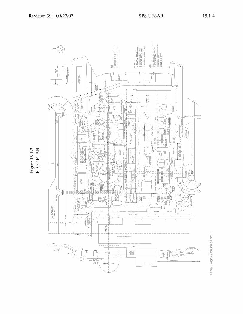
The site arrangement, plot plan, and the general arrangement of equipment within theprincipal Class I structures are shown on the Figures and Reference Drawings listed in thefollowing tabulation:
Item Reference Drawing
Site Plan Figure 15.1-1
Plot Plan Figure 15.1-2 and Reference Drawing 1
Containment Structure and Containment Auxiliary Structures
Reference Drawings 2 through 8
Auxiliary Building Reference Drawings 9, 10, 11, & 12
Fuel Building Reference Drawings 13 & 14
Control Area Reference Drawing 15

Revision 39—09/27/07 SPS UFSAR 15.1-2
15.1 REFERENCE DRAWINGS
The list of Station Drawings below is provided for information only. The referenced drawings are not part of the UFSAR. This is not intended to be a complete listing of all Station Drawings referenced from this section of the UFSAR. The contents of Station Drawings are controlled by station procedure.
Drawing Number Description
1. 11448-FY-1D Plot Plan
2. 11448-FM-1A Machine Location: Reactor Containment, Elevation 47'- 4"
3. 11448-FM-1B Machine Location: Reactor Containment, Elevation 18'- 4"
4. 11448-FM-1C Machine Location: Reactor Containment, Elevation 3'- 6"
5. 11448-FM-1D Machine Location: Reactor Containment, Elevation 27'- 7"
6. 11448-FM-1E Machine Location: Reactor Containment; Sections “A-A”, “E-E”, & “Z-Z”
7. 11448-FM-1F Machine Location: Reactor Containment; Sections “B-B”, “X-X”, & “Y-Y”
8. 11448-FM-1G Machine Location: Reactor Containment, Sections “C-C” & “D-D”
9. 11448-FM-5A Arrangement: Auxiliary Building
10. 11448-FM-5B Arrangement: Auxiliary Building, Unit 1
11. 11448-FM-5C Arrangement: Auxiliary Building
12. 11448-FM-5D Arrangement: Auxiliary Building
13. 11448-FM-9A Arrangement: Fuel Building, Sheet 1
14. 11448-FM-9B Arrangement: Fuel Building, Sheet 2, Unit 1
15. 11448-FA-1E Control and Relay Room Service Building

Revision 39—09/27/07 SPS UFSAR 15.1-3
Figu
re15
.1-1
SI
TE
PL
AN
Etia
m v
enen
atis
acc
umsa
n en
im. M
auris
rut
rum
, dia
m q
uis
tinci
dunt
ele
men
tum
, sem
orc
i bib
endu
m li
bero
, ut e
lem
entu
m
just
o m
agna
at a
ugue
. Aliq
uam
sap
ien
mas
sa, f
auci
bus
ac, e
lem
entu
m n
on, l
aore
et n
ec, f
elis
. Ves
tibul
um a
ccum
san
sagi
ttis
ipsu
m. I
n ul
lam
corp
er, d
ui s
ed c
ursu
s eu
ism
od, a
nte
wis
i dap
ibus
ligu
la, i
d rh
oncu
s ip
sum
mi a
t tel
lus.
Cla
ss a
pten
t ta
citi
soci
osqu
ad
litor
a to
rque
nt p
er c
onub
ia n
ostr
a, p
er in
cept
os h
ymen
aeos
. Qui
sque
rho
ncus
wis
i vita
e do
lor.
Etia
m
elei
fend
. Int
eger
impe
rdie
t veh
icul
a an
te. S
ed in
arc
u et
odi
o ac
cum
san
port
a. A
enea
n m
i. V
ivam
us n
on o
rci v
itae
urna
al
ique
t ulla
mco
rper
. Cla
ss a
pten
t tac
iti s
ocio
squ
ad li
tora
torq
uent
per
con
ubia
nos
tra,
per
ince
ptos
hym
enae
os. I
n fr
ingi
lla
ligul
a ve
l odi
o. In
hac
hab
itass
e pl
atea
dic
tum
st. E
tiam
tem
pus
lacu
s ac
arc
u. P
raes
ent n
on li
bero
.
Revision 39—09/27/07 SPS UFSAR 15.1-4
Figu
re 1
5.1-
2 PL
OT
PL
AN
Etia
m v
enen
atis
acc
umsa
n en
im. M
auris
rut
rum
, dia
m q
uis
tinci
dunt
ele
men
tum
, sem
orc
i bib
endu
m li
bero
, ut e
lem
entu
m
just
o m
agna
at a
ugue
. Aliq
uam
sap
ien
mas
sa, f
auci
bus
ac, e
lem
entu
m n
on, l
aore
et n
ec, f
elis
. Ves
tibul
um a
ccum
san
sagi
ttis
ipsu
m. I
n ul
lam
corp
er, d
ui s
ed c
ursu
s eu
ism
od, a
nte
wis
i dap
ibus
ligu
la, i
d rh
oncu
s ip
sum
mi a
t tel
lus.
Cla
ss a
pten
t ta
citi
soci
osqu
ad
litor
a to
rque
nt p
er c
onub
ia n
ostr
a, p
er in
cept
os h
ymen
aeos
. Qui
sque
rho
ncus
wis
i vita
e do
lor.
Etia
m
elei
fend
. Int
eger
impe
rdie
t veh
icul
a an
te. S
ed in
arc
u et
odi
o ac
cum
san
port
a. A
enea
n m
i. V
ivam
us n
on o
rci v
itae
urna
al
ique
t ulla
mco
rper
. Cla
ss a
pten
t tac
iti s
ocio
squ
ad li
tora
torq
uent
per
con
ubia
nos
tra,
per
ince
ptos
hym
enae
os. I
n fr
ingi
lla
ligul
a ve
l odi
o. In
hac
hab
itass
e pl
atea
dic
tum
st. E
tiam
tem
pus
lacu
s ac
arc
u. P
raes
ent n
on li
bero
.
Revision 39—09/27/07 SPS UFSAR 15.2-1
15.2 STRUCTURAL DESIGN CRITERIA
15.2.1 General
The structures, systems, and components of the Surry Power Station, Units No. 1 and No. 2,are classified into groupings requiring seismic, tornado or conventional design. The effects of thePower Uprating to a core power of 2546 MWt on pipe stress and supports were reviewed for thesystems listed below. The review determined that the existing piping and support configuration isadequate to withstand the increase in pressure and temperature associated with the PowerUprating.
Systems: Main Steam
Condensate
Extraction System
H. P. Heater Drain
L. P. Heater Drains
Reactor Coolant
Class I design encompasses those structures, systems or components of reactor facilitiesthat are essential to the prevention of accidents that could affect the public health and safety, or tothe mitigation of their consequences.
Structures, systems, and components are designed, fabricated, and constructed toperformance standards that will enable the facility to withstand, without loss of capability toprotect the public, the additional forces that might be imposed by:
1. The operating-basis earthquake and the design-basis earthquake.
2. Tornados and other local site effects including flooding conditions, winds, and ice. Radiationlevels that constitute a hazard to the public are defined in 10 CFR 50.67.
A Class I structure is designed for resistance to seismic loadings in accordance withSection 15.2.4 and for tornados, where applicable, in accordance with Section 15.2.3. There aresome structures, systems, or components whose loss or failure by earthquake will not affect thepublic health or safety and will permit safe station shutdown, although their loss could interruptpower generation. These structures, systems, or components are not designed for specific seismicor tornado loadings.
Structures not designed for seismic or tornado loadings are designed according toSpecification for the Design, Fabrication, and Erection of Structural Steel for Buildings(AISC-1963), and Building Code Requirements for Reinforced Concrete (ACI 318-63, Part IVA -Working Stress Design).

Revision 39—09/27/07 SPS UFSAR 15.2-2
These structures are designed for dead, live, and normal wind loads using allowable stresslevels given in the above codes.
Some structures, systems and components of the station are necessary for a safe and orderlyshutdown during a tornado. These structures are designed for tornado loadings, and systems andcomponents are protected by tornado-resistant structures.
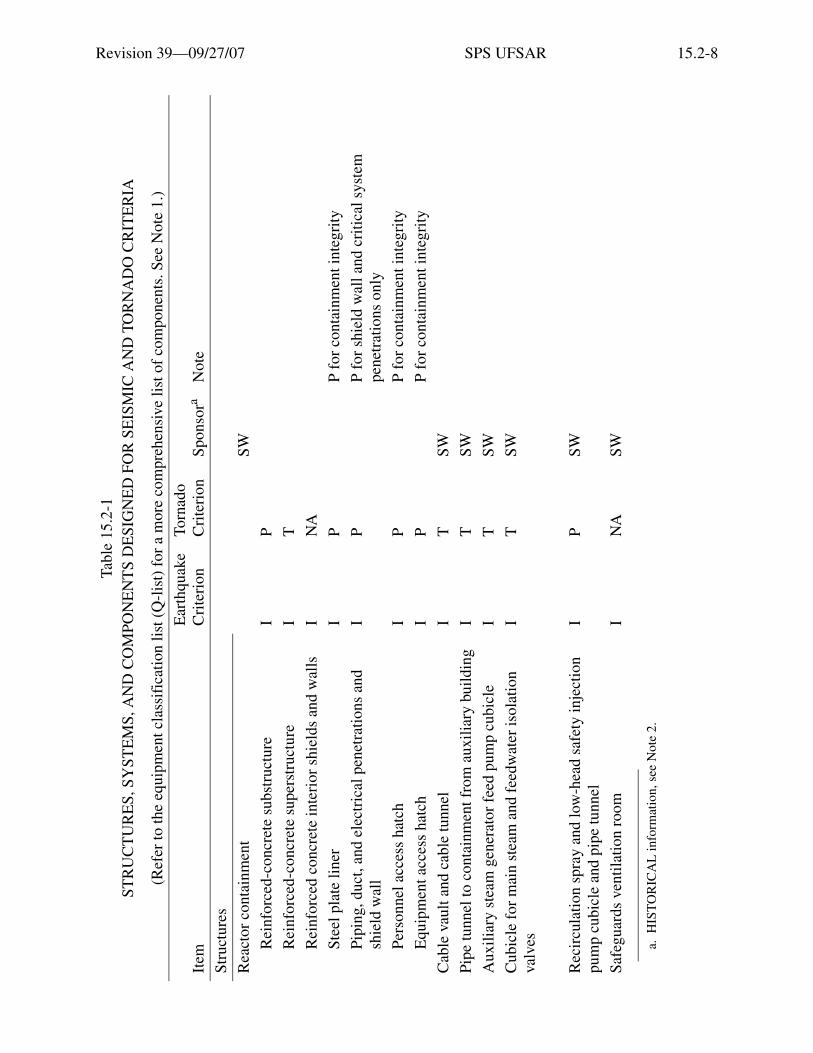
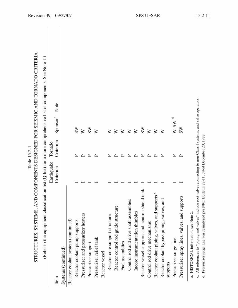
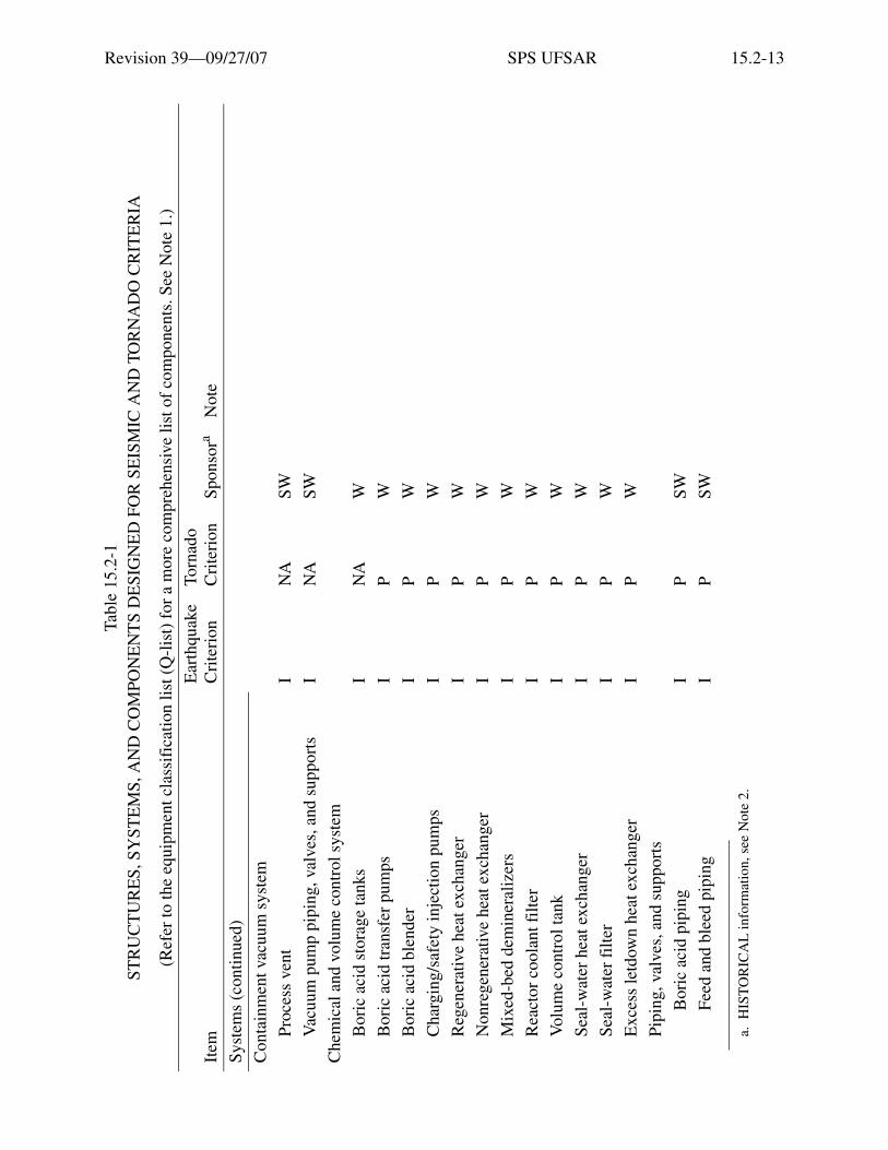
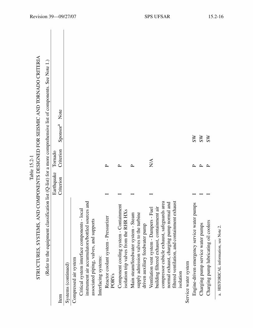
A list of the structures, systems, and components designed to satisfy seismic and/or tornadocriteria is given in Table 15.2-1.
15.2.2 Normal Wind Loading
All structures were designed to withstand the following wind loads applied to the projectedarea of all surfaces:
Elevation 26 ft. 6 in. to Elevation 56 ft. 6 in., 30 lb/ft2
Elevation 57 ft. 6 in. to Elevation 75 ft. 6 in., 35 lb/ft2
Elevation 75 ft. 6 in. to Elevation 130 ft. 0 in., 45 lb/ft2
Elevation 131 ft. 0 in. and above, 55 lb/ft2
Roofs were designed for uplift using 1.25 times the wind load taken at the correspondingelevation of the roof.
Members subject to stresses produced by this wind load combined with live and dead loadswere proportioned for stresses 33-1/3% greater than conventional working stresses, provided thatthe section thus required is not less than that required for the combination of dead and live loadscomputed without the one-third increase.
15.2.3 Tornado Criteria
Section 2.2 outlines the probability of a tornado occurring at the site. Although no structuraldamage is known to have resulted to a reinforced concrete building in a tornado (Reference 1), thestructures and systems so indicated in Table 15.2-1 are designed to ensure safe shutdown of thereactor when subjected to tornado loadings.
The tornado model used for design has the following characteristics:
Rotational velocity 300 mph
Translation velocity 60 mph
Pressure drop 3 psi in 3 sec
Overall diameter 1200 ft
Radius of maximum winds 200 ft

Revision 39—09/27/07 SPS UFSAR 15.2-3
Applicable structures are designed to resist a maximum wind velocity associated with atornado of 360 mph, which is obtained by adding the rotational and translational velocities.Structures and systems are checked for tornado pressure loading, vacuum loading, and thecombination of these two.
The tornado wind velocity is converted to an equivalent pressure, which is applied to thestructures uniformly using the formula:
P = 0.00256 V2
where:
P = equivalent pressure, lb/ft2
V = wind velocity, mph
This pressure is multiplied by applicable shape factors and drag coefficients as given inASCE Paper No. 3269 by Thomas W. Singell (Reference 2), and applied to the silhouette of thestructure.
A reduction of the full negative pressure differential is made when venting of the structuresis provided. The amount of the reduction is a function of the venting area provided.
Tornado wind loads are combined with other loads as described in Section 15.5.1.2.Tornado and earthquake loads are not considered to act simultaneously. A uniform wind velocityand a nonuniform atmospheric pressure gradient is incorporated in the design of the containmentstructure.
Structural design criteria for tornado loading for the containment structure are given inTable 15.5-1 and Section 15.5.1.5.
It is assumed that a tornado could generate either of the following potential missiles:
1. Missile equivalent to a wooden utility pole 40 feet long, 12-inch diameter, weighing 50 lb/ft3
and traveling in a vertical or horizontal direction at 150 mph.
2. Missile equivalent to a 1-ton automobile traveling at 150 mph.
The amount of penetration of the missile is determined from the Ballistic ResearchLaboratories formula (Reference 3).
The design assumes maximum wind forces and partial vacuum to occur simultaneouslywith the impact of either of the missiles singly. Allowable stresses do not exceed 90% of thecertified minimum yield strength of the steel, the capacity reduction factor given inSection 15.5.1.2 times the certified minimum yield strength of the reinforcing steel, and 75% ofthe ultimate strength of the concrete.
Revision 39—09/27/07 SPS UFSAR 15.2-4
15.2.4 Seismic Design
Class I structures, systems, and components designed to resist seismic forces are listed inTable 15.2-1. The design is based on two separate seismic criteria: the operating-basis earthquake(OBE) and the design-basis earthquake (DBE), as described in Section 2.5.
The seismic analysis of Class I structures, such as the containment structure, auxiliarybuilding, fuel building, service building (including the control room), and safeguard areas, wasbased on the modal analysis response spectra technique. Major equipment-supporting structures,such as steam generator supports, reactor coolant pump supports, and pressurizer supports, weretreated in an identical manner. Acceleration response spectra for the OBE and DBE are given onFigures 2.5-5 and 2.5-6.
Seismic loading includes the horizontal or vertical responses acceleration or combinationsof both where the effects, as measured by the separate acceleration components, of horizontal andvertical accelerations are combined to produce maximum stress intensities, taking into accountany potential adverse effect due to phase of the separate accelerations.
Damping factors for the structures, systems, and components are given in Table 15.2-2.
The design of the containment structures is based on ultimate strength design and loadingfactors as described in Section 15.5.1.2. Maximum allowable stress levels for both theoperating-basis earthquake and the design-basis earthquake are based on proportions of theminimum yield strength.
For other Class I structures, the operating-basis earthquake loading is combined with dead,live, and other static loads. Normal wind or tornado loadings are not assumed to occursimultaneously with the earthquake loading. Members are proportioned for stresses 33-1/3%greater than conventional working stresses, provided that the section thus required is not less thanthat required for the combination of dead and live loads computed without the one-third increase.Allowable soil-bearing values are increased one-third.
For Class I structures other than the containment structure, the design basis earthquake iscombined with static loads using loading combinations given in Table 15.5-1. For these structuresunder the design-basis earthquake loading, the allowable stresses do not exceed 90% of thecertified minimum yield strength for structural steel, the capacity reduction factor, given inSection 15.5.1.2, times the certified minimum yield strength for reinforcing steel, and the capacityreduction factor times the specified strength for concrete. Allowable soil bearing values areincreased by one-half.
To allow for unimpeded relative motions between structures, a rattlespace is providedbetween the:
1. Containment structures and the auxiliary building.
2. Containment structures and the fuel building.

Revision 39—09/27/07 SPS UFSAR 15.2-5
3. Containment structures and the containment auxiliary structures around the periphery of eachcontainment.
4. Fuel building and auxiliary building.
5. Auxiliary building and control area.
In general, the periphery of the rattlespace between buildings is arranged to prevent materialentering the space, with the inner areas left as a void.
Maximum relative motions between adjoining structures are included in the stress analysesof all piping that extends from one building to another.
Type “A” sand, as described in Section 2.4.3.3, was removed from under the fuel building,auxiliary building, and control area and replaced by a dense graded granular fill material asdescribed in Section 2.4.5.1.
The analytical procedure used for the nuclear steam supply system is described bySection 15A.3 of Appendix 15A.
The reactor protection system, engineered safety feature (ESF) circuits, and the emergencypower system are designed so that they will not lose the capability to shut the plant down andmaintain it in a safe shutdown condition under operating-basis earthquake or design-basisearthquake conditions. For the design-basis earthquake, permanent deformation of the equipmentis allowable, provided that the capability to perform its function is maintained.
Typical protection system equipment is subjected to type tests under simulated seismicaccelerations to demonstrate its ability to perform its functions. Type testing was performed usingconservatively large accelerations and applicable frequencies. Analyses were done for structuresthat were not done for the reactor protection system equipment. However, the peak accelerationsand frequencies were checked against those derived by structural analyses of operational anddesign-basis earthquake loadings.
A Westinghouse topical report, WCAP-7397-L, provides the seismic evaluation ofsafety-related equipment. The type tests covered by this report are applicable to the Surry PowerStation, with the exception of the process control equipment, which is covered in a supplement toWCAP-7397-L.
The emergency switchgear has been tested under seismic conditions, and manufacturers’test data are available. The emergency generator and control panels are identical with those usedin locomotives, and have been tested under severe conditions, but no seismic tests have beenmade.
The control board was designed to withstand earthquake conditions, and an analysis wasperformed to verify the adequacy of the seismic design, but tests were not performed.

Revision 39—09/27/07 SPS UFSAR 15.2-6
The emergency batteries are supported on rigid reinforced concrete pedestals firmlyanchored to the floor. Steel retaining members integral with the pedestals prevent the batteriesfrom being dislodged under seismic excitation.
15.2.5 Hydrostatic Loadings
Finish ground grade at the station is at Elevation 26 ft. 6 in. Natural ground water level is atapproximately Elevation 4 ft. 0 in.
The exterior wall of the containment structure extends approximately 66 feet below thefinished ground level. Water-resistant membrane protection for this structure is defined inSections 15.5.1.9 and 15.5.1.10. External pumps for reducing the hydrostatic head on thecontainment structure are described in Section 15.5.1.3. This latter section also discusses theeffect of the buoyant pressure on the containment structure.
Exterior surfaces of walls of other Class I structures with floor levels below Elevation 26 ft.6 in. are covered with a mopped-on bitumastic coating to establish a water-resistant membrane.

Revision 39—09/27/07 SPS UFSAR 15.2-7
15.2 REFERENCES
1. V. C. Gilberton and E. E. Mageanu, Tornadoes, AIA Technical Reference Guide, TRG 13-2,U. S. Weather Bureau.
2. T. W. Singell, Wind Forces on Structures: Forces on Enclosed Structures, Journal of theStructural Division of the ASCE, July 1958.
3. C. R. Russell, Reactor Safeguards, MacMillan, 1962.
4. Letter, NRC to Vepco, Serial #85-885, dated December 4, 1985
5. ASME Boiler and Pressure Vessel Code, Section III, Division I, Code Case N-411,Alternative Damping Values for Seismic Analysis of Piping Sections, American Society ofMechanical Engineers, 345 E. 47th Street, New York, NY 10017, dated September 17, 1984.
6. NRC Bulletin No. 88-11: Pressurizer Surge Line Thermal Stratification, USNRC,December 20, 1988.
7. Virginia Power Letters Serial Nos. 89-006A dated May 3, 1989 and 89-006B datedNovember 13, 1989 to United States Nuclear Regulatory Commission.
8. Revised report on the Reanalysis of Safety-Related Piping Systems - Surry Power Station,Unit 1, August 1979, by Stone & Webster Engineering Corporation.
9. Report on the I.E. Bulletin 79-14, Analysis for As-Built Safety-Related Piping Systems -Surry Power Station - Unit 2, July 1981, by Ebasco Services, Inc.
10. Report on the Reanalysis of Safety-Related Piping Systems - Surry Power Station - Unit 2,Rev. 1, April 1980, by Ebasco Services, Inc.
11. Mitsubishi Heavy Industries, LTD., Design Report DG KCS-03-0008, Dominion Generation,Surry Power Station Unit 2, Control Rod Drive Mechanism Design Report, Rev. 3.
Revision 39—09/27/07 SPS UFSAR 15.2-8
Tabl
e 15
.2-1
STR
UC
TU
RE
S, S
YST
EM
S, A
ND
CO
MPO
NE
NT
S D
ESI
GN
ED
FO
R S
EIS
MIC
AN
D T
OR
NA
DO
CR
ITE
RIA
(Ref
er to
the
equi
pmen
t cla
ssif
icat
ion
list (
Q-l
ist)
for
a m
ore
com
preh
ensi
ve li
st o
f co
mpo
nent
s. S
ee N
ote
1.)
Item
Ear
thqu
ake
Cri
teri
onTo
rnad
oC
rite
rion
Spon
sora
Not
e
Stru
ctur
es
Rea
ctor
con
tain
men
tSW
Rei
nfor
ced-
conc
rete
sub
stru
ctur
eI
P
Rei
nfor
ced-
conc
rete
sup
erst
ruct
ure
IT
Rei
nfor
ced
conc
rete
inte
rior
shi
elds
and
wal
lsI
NA
Stee
l pla
te li
ner
IP
P fo
r co
ntai
nmen
t int
egri
ty
Pipi
ng, d
uct,
and
elec
tric
al p
enet
ratio
ns a
nd
shie
ld w
all
IP
P fo
r sh
ield
wal
l and
cri
tical
sys
tem
pe
netr
atio
ns o
nly
Pers
onne
l acc
ess
hatc
hI
PP
for
cont
ainm
ent i
nteg
rity
Equ
ipm
ent a
cces
s ha
tch
IP
P fo
r co
ntai
nmen
t int
egri
ty
Cab
le v
ault
and
cabl
e tu
nnel
IT
SW
Pipe
tunn
el to
con
tain
men
t fro
m a
uxili
ary
build
ing
IT
SW
Aux
iliar
y st
eam
gen
erat
or f
eed
pum
p cu
bicl
eI
TSW
Cub
icle
for
mai
n st
eam
and
fee
dwat
er is
olat
ion
valv
esI
TSW
Rec
ircu
latio
n sp
ray
and
low
-hea
d sa
fety
inje
ctio
n pu
mp
cubi
cle
and
pipe
tunn
elI
PSW
Safe
guar
ds v
entil
atio
n ro
omI
NA
SW
a.H
IST
OR
ICA
L in
form
atio
n, s
ee N
ote
2.

Revision 39—09/27/07 SPS UFSAR 15.2-9
Stru
ctur
es (
cont
inue
d)
Aux
iliar
y bu
ildin
gSW
Rei
nfor
ced-
conc
rete
str
uctu
reI
T
Stee
l sup
erst
ruct
ure
IN
A
Vac
uum
equ
ipm
ent a
rea
IN
A
Fuel
bui
ldin
gSW
Rei
nfor
ced-
conc
rete
str
uctu
reI
TT
for
hor
izon
tal m
issi
le o
nly
Stee
l sup
erst
ruct
ure
IT
T f
or to
rnad
o w
inds
onl
y
Spen
t-fu
el s
tora
ge r
ack
IP
P fo
r ho
rizo
ntal
mis
sile
onl
y
Fuel
-han
dlin
g tr
olle
y su
ppor
t str
uctu
reI
TT
for
torn
ado
win
ds o
nly
Con
trol
roo
mI
TSW
Em
erge
ncy
switc
hgea
r an
d re
lay
room
IT
SW
Bat
tery
roo
ms
IT
SW
Air
-con
ditio
ning
equ
ipm
ent r
oom
IT
SWFo
r co
ntro
l roo
m a
nd r
elay
roo
m o
nly
Rea
ctor
trip
bre
aker
cub
icle
IT
SW
Em
erge
ncy
dies
el-g
ener
ator
roo
ms
SW
Rei
nfor
ced-
conc
rete
flo
orI
T
Wal
ls, e
xclu
ding
louv
ers
IT
Roo
f sl
abI
T
a.H
IST
OR
ICA
L in
form
atio
n, s
ee N
ote
2.
Tabl
e 15
.2-1
STR
UC
TU
RE
S, S
YST
EM
S, A
ND
CO
MPO
NE
NT
S D
ESI
GN
ED
FO
R S
EIS
MIC
AN
D T
OR
NA
DO
CR
ITE
RIA
(Ref
er to
the
equi
pmen
t cla
ssif
icat
ion
list (
Q-l
ist)
for
a m
ore
com
preh
ensi
ve li
st o
f co
mpo
nent
s. S
ee N
ote
1.)
Item
Ear
thqu
ake
Cri
teri
onTo
rnad
oC
rite
rion
Spon
sora
Not
e

Revision 39—09/27/07 SPS UFSAR 15.2-10
Stru
ctur
es (
cont
inue
d)
Tur
bine
bui
ldin
gN
AN
ASW
By
desi
gn, b
uild
ing
colla
pse
will
not
da
mag
e an
y C
lass
I s
truc
ture
s an
d co
mpo
nent
s du
ring
ear
thqu
ake,
or
torn
ado-
resi
stan
t str
uctu
res
and
com
pone
nts
duri
ng to
rnad
o
Mec
hani
cal E
quip
men
t Roo
m-5
IT
Cir
cula
ting
wat
er p
ump
inta
ke s
truc
ture
IT
SWT
for
em
erge
ncy
serv
ice
wat
er p
ump
cubi
cle
only
Hig
h-le
vel i
ntak
e st
ruct
ures
IT
SWT,
no
mis
sile
pro
tect
ion
requ
ired
Seal
pits
IT
SWT,
no
mis
sile
pro
tect
ion
requ
ired
Hig
h-le
vel i
ntak
e ca
nal
IN
ASW
Fire
-pum
p ho
use
IT
SWE
ngin
e-dr
iven
pum
p on
ly
Fuel
-oil
tran
sfer
pum
p va
ult
IT
SW
Bor
on r
ecov
ery
tank
dik
esI
TSW
Syst
ems
Rea
ctor
coo
lant
sys
tem
Stea
m g
ener
ator
sI
PW
Stea
m g
ener
ator
sup
port
sI
PSW
Rea
ctor
coo
lant
pum
psb
IP
W
a.H
IST
OR
ICA
L in
form
atio
n, s
ee N
ote
2.
b.A
ll r
efer
ence
s to
“pu
mps
” in
clud
e dr
iver
s.
Tabl
e 15
.2-1
STR
UC
TU
RE
S, S
YST
EM
S, A
ND
CO
MPO
NE
NT
S D
ESI
GN
ED
FO
R S
EIS
MIC
AN
D T
OR
NA
DO
CR
ITE
RIA
(Ref
er to
the
equi
pmen
t cla
ssif
icat
ion
list (
Q-l
ist)
for
a m
ore
com
preh
ensi
ve li
st o
f co
mpo
nent
s. S
ee N
ote
1.)
Item
Ear
thqu
ake
Cri
teri
onTo
rnad
oC
rite
rion
Spon
sora
Not
e
Revision 39—09/27/07 SPS UFSAR 15.2-11
Syst
ems
(con
tinue
d)
Rea
ctor
coo
lant
sys
tem
(co
ntin
ued)
Rea
ctor
coo
lant
pum
p su
ppor
tsI
PSW
Pres
suri
zer
and
pres
suri
zer
heat
ers
IP
W
Pres
suri
zer
supp
ort
IP
SW
Pres
suri
zer
relie
f ta
nkI
PW
Rea
ctor
ves
sel
Rea
ctor
cor
e su
ppor
t str
uctu
reI
PW
Rea
ctor
con
trol
rod
gui
de s
truc
ture
IP
W
Fuel
ass
embl
ies
IP
W
Con
trol
rod
and
dri
ve s
haft
ass
embl
ies
IP
W
Inco
re in
stru
men
tatio
n th
imbl
esI
PW
Rea
ctor
ves
sel s
uppo
rts
and
neut
ron
shie
ld ta
nkI
PSW
Con
trol
rod
dri
ve m
echa
nism
sI
PW
Rea
ctor
coo
lant
pip
ing,
val
ves,
and
sup
port
s c
IP
W
Rea
ctor
coo
lant
byp
ass
pipi
ng, v
alve
s, a
nd
supp
orts
IP
W
Pres
suri
zer
surg
e lin
eI
PW
, SW
d
Pres
suri
zer
spra
y lin
es, v
alve
s, a
nd s
uppo
rts
IP
SW
a.H
IST
OR
ICA
L in
form
atio
n, s
ee N
ote
2.
c.A
ll r
efer
ence
s to
“pi
ping
and
val
ves”
incl
ude
root
val
ves
conn
ecti
ng to
non
-Cla
ss I
sys
tem
s, a
nd v
alve
ope
rato
rs.
d.Pr
essu
rize
r su
rge
line
was
rea
naly
zed
per
NR
C B
ulle
tin 8
8-11
, dat
ed D
ecem
ber
20, 1
988.
Tabl
e 15
.2-1
STR
UC
TU
RE
S, S
YST
EM
S, A
ND
CO
MPO
NE
NT
S D
ESI
GN
ED
FO
R S
EIS
MIC
AN
D T
OR
NA
DO
CR
ITE
RIA
(Ref
er to
the
equi
pmen
t cla
ssif
icat
ion
list (
Q-l
ist)
for
a m
ore
com
preh
ensi
ve li
st o
f co
mpo
nent
s. S
ee N
ote
1.)
Item
Ear
thqu
ake
Cri
teri
onTo
rnad
oC
rite
rion
Spon
sora
Not
e

Revision 39—09/27/07 SPS UFSAR 15.2-12
Syst
ems
(con
tinue
d)
Rea
ctor
coo
lant
sys
tem
(co
ntin
ued)
Pres
suri
zer
safe
ty a
nd r
elie
f va
lves
IP
W
Safe
ty in
ject
ion
syst
em
Acc
umul
ator
s an
d su
ppor
tsI
NA
W
Low
-hea
d sa
fety
inje
ctio
n pu
mps
and
pip
ing
IP
W P
for
con
tain
men
t int
egri
ty
Bor
ic a
cid
inje
ctio
n ta
nks
and
pipi
ngI
PW
Pipi
ng, v
alve
s, a
nd s
uppo
rts
IN
ASW
Exc
ept d
rain
/sam
ple
lines
Con
tain
men
t spr
ay s
yste
m
Ref
uelin
g w
ater
sto
rage
tank
IN
ASW
Con
tain
men
t spr
ay p
umps
IN
ASW
Pipi
ng, v
alve
s, a
nd s
uppo
rts
IN
ASW
Exc
ept r
ecir
cula
tion
lines
Ref
uelin
g w
ater
che
mic
al a
dditi
on ta
nkI
NA
SW
Rec
ircu
latio
n sp
ray
syst
ems
Rec
ircu
latio
n sp
ray
pum
ps a
nd p
ipin
gI
PSW
P fo
r co
ntai
nmen
t int
egri
ty
Rec
ircu
latio
n sp
ray
heat
exc
hang
ers
IN
ASW
Rea
ctor
con
tain
men
t sum
p an
d sc
reen
sI
NA
SW
Pipi
ng, v
alve
s, a
nd s
uppo
rts
IN
ASW
a.H
IST
OR
ICA
L in
form
atio
n, s
ee N
ote
2.
Tabl
e 15
.2-1
STR
UC
TU
RE
S, S
YST
EM
S, A
ND
CO
MPO
NE
NT
S D
ESI
GN
ED
FO
R S
EIS
MIC
AN
D T
OR
NA
DO
CR
ITE
RIA
(Ref
er to
the
equi
pmen
t cla
ssif
icat
ion
list (
Q-l
ist)
for
a m
ore
com
preh
ensi
ve li
st o
f co
mpo
nent
s. S
ee N
ote
1.)
Item
Ear
thqu
ake
Cri
teri
onTo
rnad
oC
rite
rion
Spon
sora
Not
e
Revision 39—09/27/07 SPS UFSAR 15.2-13
Syst
ems
(con
tinue
d)
Con
tain
men
t vac
uum
sys
tem
Proc
ess
vent
IN
ASW
Vac
uum
pum
p pi
ping
, val
ves,
and
sup
port
sI
NA
SW
Che
mic
al a
nd v
olum
e co
ntro
l sys
tem
Bor
ic a
cid
stor
age
tank
sI
NA
W
Bor
ic a
cid
tran
sfer
pum
psI
PW
Bor
ic a
cid
blen
der
IP
W
Cha
rgin
g/sa
fety
inje
ctio
n pu
mps
IP
W
Reg
ener
ativ
e he
at e
xcha
nger
IP
W
Non
rege
nera
tive
heat
exc
hang
erI
PW
Mix
ed-b
ed d
emin
eral
izer
sI
PW
Rea
ctor
coo
lant
filt
erI
PW
Vol
ume
cont
rol t
ank
IP
W
Seal
-wat
er h
eat e
xcha
nger
IP
W
Seal
-wat
er f
ilte
rI
PW
Exc
ess
letd
own
heat
exc
hang
erI
PW
Pipi
ng, v
alve
s, a
nd s
uppo
rts
Bor
ic a
cid
pipi
ngI
PSW
Feed
and
ble
ed p
ipin
gI
PSW
a.H
IST
OR
ICA
L in
form
atio
n, s
ee N
ote
2.
Tabl
e 15
.2-1
STR
UC
TU
RE
S, S
YST
EM
S, A
ND
CO
MPO
NE
NT
S D
ESI
GN
ED
FO
R S
EIS
MIC
AN
D T
OR
NA
DO
CR
ITE
RIA
(Ref
er to
the
equi
pmen
t cla
ssif
icat
ion
list (
Q-l
ist)
for
a m
ore
com
preh
ensi
ve li
st o
f co
mpo
nent
s. S
ee N
ote
1.)
Item
Ear
thqu
ake
Cri
teri
onTo
rnad
oC
rite
rion
Spon
sora
Not
e

Revision 39—09/27/07 SPS UFSAR 15.2-14
Syst
ems
(con
tinue
d)
Che
mic
al a
nd v
olum
e co
ntro
l sys
tem
(co
ntin
ued)
Pipi
ng, v
alve
s, a
nd s
uppo
rts
(con
tinue
d)
Hyd
roge
n, n
itrog
en, a
nd v
ent p
ipin
g fo
r vo
lum
e co
ntro
l tan
kI
PSW
Res
idua
l hea
t rem
oval
sys
tem
Res
idua
l hea
t rem
oval
pum
psI
PW
Res
idua
l hea
t exc
hang
ers
IP
W
Pipi
ng, v
alve
s, a
nd s
uppo
rts
IP
SW
Bor
on r
ecov
ery
syst
em
Gas
str
ippe
rI
PSW
Gas
str
ippe
r ov
erhe
ad c
onde
nser
IP
SW
Prim
ary
drai
n ta
nkI
PSW
Prim
ary
drai
n ta
nk v
ent c
hille
r co
nden
ser
IP
SW
Ove
rhea
d ga
s co
mpr
esso
rsI
PSW
Gas
str
ippe
r su
rge
tank
IP
SW
Com
pone
nt c
oolin
g sy
stem
Com
pone
nt c
oolin
g pu
mps
IP
SW
Com
pone
nt c
oolin
g w
ater
hea
t exc
hang
ers
IP
SW
Com
pone
nt c
oolin
g su
rge
tank
IP
SW
a.H
IST
OR
ICA
L in
form
atio
n, s
ee N
ote
2.
Tabl
e 15
.2-1
STR
UC
TU
RE
S, S
YST
EM
S, A
ND
CO
MPO
NE
NT
S D
ESI
GN
ED
FO
R S
EIS
MIC
AN
D T
OR
NA
DO
CR
ITE
RIA
(Ref
er to
the
equi
pmen
t cla
ssif
icat
ion
list (
Q-l
ist)
for
a m
ore
com
preh
ensi
ve li
st o
f co
mpo
nent
s. S
ee N
ote
1.)
Item
Ear
thqu
ake
Cri
teri
onTo
rnad
oC
rite
rion
Spon
sora
Not
e

Revision 39—09/27/07 SPS UFSAR 15.2-15
Syst
ems
(con
tinue
d)
Com
pone
nt c
oolin
g sy
stem
(co
ntin
ued)
Pipi
ng, v
alve
s, a
nd s
uppo
rts
For
resi
dual
hea
t exc
hang
ers
IP
SW
For
fuel
poo
l coo
lers
IP
SWP
for
hori
zont
al m
issi
le o
nly
RC
P th
erm
al b
arri
er s
uppl
y pi
ping
fro
m th
e up
stre
am c
heck
val
ves
to th
e R
CPs
IP
SW
Cha
rgin
g pu
mp
com
pone
nt c
oolin
g w
ater
sy
stem C
harg
ing
pum
p co
mpo
nent
coo
ling
wat
er
pum
psI
PSW
Cha
rgin
g pu
mp
mec
hani
cal s
eal c
oole
rsI
PSW
Cha
rgin
g pu
mp
seal
coo
ling
surg
e ta
nkI
PSW
Cha
rgin
g pu
mp
inte
rmed
iate
sea
l coo
lers
IP
SW
Pipi
ng, v
alve
s, a
nd s
uppo
rts
IP
SW
Fuel
poo
l coo
ling
syst
em
Fuel
poo
l pum
psI
PSW
P fo
r ho
rizo
ntal
mis
sile
onl
y
Fuel
poo
l coo
lers
IP
SWP
for
hori
zont
al m
issi
le o
nly
Pipi
ng, v
alve
s, a
nd s
uppo
rts
conn
ectin
g ab
ove
equi
pmen
t to
spen
t-fu
el p
ool
IP
SWP
for
hori
zont
al m
issi
le o
nly
a.H
IST
OR
ICA
L in
form
atio
n, s
ee N
ote
2.
Tabl
e 15
.2-1
STR
UC
TU
RE
S, S
YST
EM
S, A
ND
CO
MPO
NE
NT
S D
ESI
GN
ED
FO
R S
EIS
MIC
AN
D T
OR
NA
DO
CR
ITE
RIA
(Ref
er to
the
equi
pmen
t cla
ssif
icat
ion
list (
Q-l
ist)
for
a m
ore
com
preh
ensi
ve li
st o
f co
mpo
nent
s. S
ee N
ote
1.)
Item
Ear
thqu
ake
Cri
teri
onTo
rnad
oC
rite
rion
Spon
sora
Not
e
Revision 39—09/27/07 SPS UFSAR 15.2-16
Syst
ems
(con
tinue
d)
Com
pres
sed
air
syst
em
Cri
tical
sys
tem
inte
rfac
e co
mpo
nent
s -
loca
l in
stru
men
t air
acc
umul
ator
s/bo
ttled
sou
rces
and
as
soci
ated
pip
ing,
val
ves,
and
sup
port
s
Inte
rfac
ing
syst
ems:
Rea
ctor
coo
lant
sys
tem
- P
ress
uriz
er
POR
Vs
IP
Com
pone
nt c
oolin
g sy
stem
- C
onta
inm
ent
isol
atio
n tr
ip v
alve
s fr
om th
e R
HR
HX
sI
P
Mai
n st
eam
/fee
dwat
er s
yste
m -
Ste
am
supp
ly a
dmis
sion
val
ves
to th
e tu
rbin
e dr
iven
aux
iliar
y fe
edw
ater
pum
p
IP
Ven
tilat
ion
vent
sys
tem
- D
ampe
rs -
Fue
l bu
ildin
g fi
ltere
d ex
haus
t, co
ntai
nmen
t air
co
mpr
esso
r cub
icle
exh
aust
, saf
egua
rds
area
no
rmal
exh
aust
, cha
rgin
g pu
mp
norm
al a
nd
filte
red
vent
ilatio
n, a
nd c
onta
inm
ent e
xhau
st
isol
atio
n
IN
/A
Serv
ice
wat
er s
yste
m
Eng
ine-
driv
en e
mer
genc
y se
rvic
e w
ater
pum
psI
PSW
Cha
rgin
g pu
mp
serv
ice
wat
er p
umps
IP
SW
Cha
rgin
g pu
mp
lubr
icat
ing
oil c
oole
rsI
PSW
a.H
IST
OR
ICA
L in
form
atio
n, s
ee N
ote
2.
Tabl
e 15
.2-1
STR
UC
TU
RE
S, S
YST
EM
S, A
ND
CO
MPO
NE
NT
S D
ESI
GN
ED
FO
R S
EIS
MIC
AN
D T
OR
NA
DO
CR
ITE
RIA
(Ref
er to
the
equi
pmen
t cla
ssif
icat
ion
list (
Q-l
ist)
for
a m
ore
com
preh
ensi
ve li
st o
f co
mpo
nent
s. S
ee N
ote
1.)
Item
Ear
thqu
ake
Cri
teri
onTo
rnad
oC
rite
rion
Spon
sora
Not
e
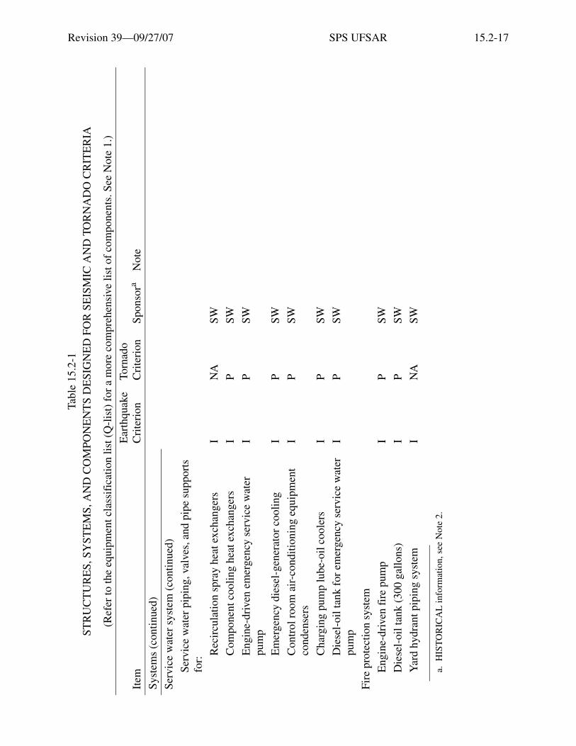
Revision 39—09/27/07 SPS UFSAR 15.2-17
Syst
ems
(con
tinue
d)
Serv
ice
wat
er s
yste
m (
cont
inue
d)
Serv
ice
wat
er p
ipin
g, v
alve
s, a
nd p
ipe
supp
orts
fo
r:
Rec
ircu
latio
n sp
ray
heat
exc
hang
ers
IN
ASW
Com
pone
nt c
oolin
g he
at e
xcha
nger
sI
PSW
Eng
ine-
driv
en e
mer
genc
y se
rvic
e w
ater
pu
mp
IP
SW
Em
erge
ncy
dies
el-g
ener
ator
coo
ling
IP
SW
Con
trol
roo
m a
ir-c
ondi
tioni
ng e
quip
men
t co
nden
sers
IP
SW
Cha
rgin
g pu
mp
lube
-oil
cool
ers
IP
SW
Die
sel-
oil t
ank
for
emer
genc
y se
rvic
e w
ater
pu
mp
IP
SW
Fire
pro
tect
ion
syst
em
Eng
ine-
driv
en f
ire
pum
pI
PSW
Die
sel-
oil t
ank
(300
gal
lons
)I
PSW
Yar
d hy
dran
t pip
ing
syst
emI
NA
SW
a.H
IST
OR
ICA
L in
form
atio
n, s
ee N
ote
2.
Tabl
e 15
.2-1
STR
UC
TU
RE
S, S
YST
EM
S, A
ND
CO
MPO
NE
NT
S D
ESI
GN
ED
FO
R S
EIS
MIC
AN
D T
OR
NA
DO
CR
ITE
RIA
(Ref
er to
the
equi
pmen
t cla
ssif
icat
ion
list (
Q-l
ist)
for
a m
ore
com
preh
ensi
ve li
st o
f co
mpo
nent
s. S
ee N
ote
1.)
Item
Ear
thqu
ake
Cri
teri
onTo
rnad
oC
rite
rion
Spon
sora
Not
e
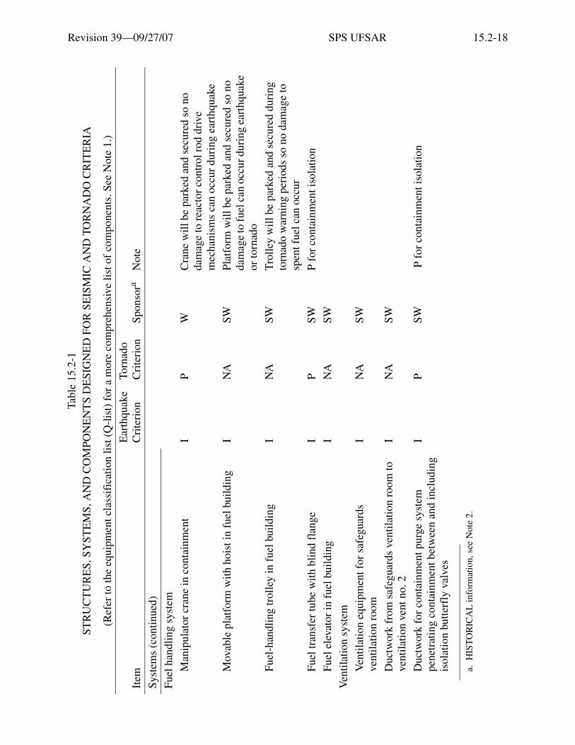
Revision 39—09/27/07 SPS UFSAR 15.2-18
Syst
ems
(con
tinue
d)
Fuel
han
dlin
g sy
stem
Man
ipul
ator
cra
ne in
con
tain
men
tI
PW
Cra
ne w
ill b
e pa
rked
and
sec
ured
so
no
dam
age
to r
eact
or c
ontr
ol r
od d
rive
m
echa
nism
s ca
n oc
cur
duri
ng e
arth
quak
e
Mov
able
pla
tfor
m w
ith h
oist
in f
uel b
uild
ing
IN
ASW
Plat
form
will
be
park
ed a
nd s
ecur
ed s
o no
da
mag
e to
fuel
can
occ
ur d
urin
g ea
rthq
uake
or
torn
ado
Fuel
-han
dlin
g tr
olle
y in
fue
l bui
ldin
gI
NA
SWT
rolle
y w
ill b
e pa
rked
and
sec
ured
dur
ing
torn
ado
war
ning
per
iods
so
no d
amag
e to
sp
ent f
uel c
an o
ccur
Fuel
tran
sfer
tube
with
blin
d fl
ange
IP
SWP
for
cont
ainm
ent i
sola
tion
Fuel
ele
vato
r in
fue
l bui
ldin
gI
NA
SW
Ven
tilat
ion
syst
em
Ven
tilat
ion
equi
pmen
t for
saf
egua
rds
vent
ilatio
n ro
omI
NA
SW
Duc
twor
k fr
om s
afeg
uard
s ve
ntila
tion
room
to
vent
ilatio
n ve
nt n
o.2
IN
ASW
Duc
twor
k fo
r co
ntai
nmen
t pur
ge s
yste
m
pene
trat
ing
cont
ainm
ent b
etw
een
and
incl
udin
g is
olat
ion
butte
rfly
val
ves
IP
SW P
for
con
tain
men
t iso
latio
n
a.H
IST
OR
ICA
L in
form
atio
n, s
ee N
ote
2.
Tabl
e 15
.2-1
STR
UC
TU
RE
S, S
YST
EM
S, A
ND
CO
MPO
NE
NT
S D
ESI
GN
ED
FO
R S
EIS
MIC
AN
D T
OR
NA
DO
CR
ITE
RIA
(Ref
er to
the
equi
pmen
t cla
ssif
icat
ion
list (
Q-l
ist)
for
a m
ore
com
preh
ensi
ve li
st o
f co
mpo
nent
s. S
ee N
ote
1.)
Item
Ear
thqu
ake
Cri
teri
onTo
rnad
oC
rite
rion
Spon
sora
Not
e

Revision 39—09/27/07 SPS UFSAR 15.2-19
Syst
ems
(con
tinue
d)
Ven
tilat
ion
syst
em (
cont
inue
d)
Air
-con
ditio
ning
equ
ipm
ent f
or m
ain
cont
rol
room
and
rel
ay r
oom
IP
SW
Em
erge
ncy
mai
n co
ntro
l and
rel
ay r
oom
ve
ntila
tion
IP
SW
Ven
tilat
ion
vent
no.
2I
NA
SW
Con
trol
rod
dri
ve v
entil
atio
n fa
ns
NA
PSW
Mai
n st
eam
sys
tem
Stea
m p
ipin
g fr
om m
ain
stea
m li
nes
to a
uxili
ary
stea
m g
ener
ator
fee
d pu
mp
turb
ine
IP
SW
Mai
n st
eam
pip
ing
from
ste
am g
ener
ator
s to
and
in
clud
ing
mai
n st
eam
trip
val
veI
PSW
Mai
n st
eam
pip
ing,
val
ves,
and
sup
port
s fr
om
trip
val
ves
to a
nd in
clud
ing
turb
ine
stop
val
ves
NA
NA
SWC
heck
was
mad
e th
at d
esig
n-ba
sis
eart
hqua
ke w
ould
not
cau
se f
ailu
re to
fu
nctio
n
Tur
bine
ste
am b
ypas
s pi
ping
, val
ves,
and
su
ppor
ts to
con
dens
erN
AN
ASW
a.H
IST
OR
ICA
L in
form
atio
n, s
ee N
ote
2.
Tabl
e 15
.2-1
STR
UC
TU
RE
S, S
YST
EM
S, A
ND
CO
MPO
NE
NT
S D
ESI
GN
ED
FO
R S
EIS
MIC
AN
D T
OR
NA
DO
CR
ITE
RIA
(Ref
er to
the
equi
pmen
t cla
ssif
icat
ion
list (
Q-l
ist)
for
a m
ore
com
preh
ensi
ve li
st o
f co
mpo
nent
s. S
ee N
ote
1.)
Item
Ear
thqu
ake
Cri
teri
onTo
rnad
oC
rite
rion
Spon
sora
Not
e

Revision 39—09/27/07 SPS UFSAR 15.2-20
Syst
ems
(con
tinue
d)
Cir
cula
ting
wat
er s
yste
m
Con
dens
erN
AN
ASW
Che
ck w
as m
ade
that
con
dens
er w
ater
bo
xes
will
not
fai
l dur
ing
eart
hqua
ke
Cir
cula
ting
wat
er p
ipin
g, v
alve
s, a
nd s
uppo
rts
from
hig
h-le
vel i
ntak
e ca
nal t
o ci
rcul
atin
g w
ater
di
scha
rge
tunn
el to
and
incl
udin
g co
nden
ser
inta
ke b
utte
rfly
val
ve; c
onde
nser
dis
char
ge
butte
rfly
val
ve
IP
SWP,
und
ergr
ound
Cir
cula
ting
wat
er d
isch
arge
tunn
elI
PSW
Cir
cula
ting
wat
er p
ump
vacu
um b
reak
erN
AN
ASW
No
cred
ible
fai
lure
mod
e fo
r pa
ssiv
e va
cuum
bre
aker
Con
dens
ate
and
feed
wat
er s
yste
m
Em
erge
ncy
cond
ensa
te s
tora
ge ta
nkI
PSW
Em
erge
ncy
cond
ensa
te m
akeu
p ta
nkI
PSW
Aux
iliar
y st
eam
gen
erat
or f
eed
pum
psI
PSW
a.H
IST
OR
ICA
L in
form
atio
n, s
ee N
ote
2.
Tabl
e 15
.2-1
STR
UC
TU
RE
S, S
YST
EM
S, A
ND
CO
MPO
NE
NT
S D
ESI
GN
ED
FO
R S
EIS
MIC
AN
D T
OR
NA
DO
CR
ITE
RIA
(Ref
er to
the
equi
pmen
t cla
ssif
icat
ion
list (
Q-l
ist)
for
a m
ore
com
preh
ensi
ve li
st o
f co
mpo
nent
s. S
ee N
ote
1.)
Item
Ear
thqu
ake
Cri
teri
onTo
rnad
oC
rite
rion
Spon
sora
Not
e

Revision 39—09/27/07 SPS UFSAR 15.2-21
Syst
ems
(con
tinue
d)
Con
dens
ate
and
feed
wat
er s
yste
m (
cont
inue
d)
Pipi
ng, v
alve
s, a
nd s
uppo
rts
Em
erge
ncy
cond
ensa
te s
tora
ge ta
nk to
au
xilia
ry s
team
gen
erat
or f
eed
pum
pI
PSW
From
aux
iliar
y st
eam
gen
erat
or f
eed
pum
ps
to s
team
gen
erat
or f
eed
lines
IP
SW
Stea
m g
ener
ator
fee
d lin
es in
side
con
tain
men
t to
and
incl
udin
g fi
rst i
sola
tion
chec
k va
lve
outs
ide
cont
ainm
ent
IP
SW
Prim
ary
vent
and
dra
in s
yste
m
Prim
ary
drai
n co
oler
IP
W
Pipi
ng, v
alve
s, a
nd s
uppo
rts
IP
SW
Prim
ary
drai
n tr
ansf
er ta
nkI
PSW
Seco
ndar
y ve
nt a
nd d
rain
sys
tem
Stea
m g
ener
ator
blo
wdo
wn
pipi
ng, v
alve
s, a
nd
supp
orts
insi
de c
onta
inm
ent t
o an
d in
clud
ing
firs
t iso
latio
n tr
ip v
alve
s
IP
SW
a.H
IST
OR
ICA
L in
form
atio
n, s
ee N
ote
2.
Tabl
e 15
.2-1
STR
UC
TU
RE
S, S
YST
EM
S, A
ND
CO
MPO
NE
NT
S D
ESI
GN
ED
FO
R S
EIS
MIC
AN
D T
OR
NA
DO
CR
ITE
RIA
(Ref
er to
the
equi
pmen
t cla
ssif
icat
ion
list (
Q-l
ist)
for
a m
ore
com
preh
ensi
ve li
st o
f co
mpo
nent
s. S
ee N
ote
1.)
Item
Ear
thqu
ake
Cri
teri
onTo
rnad
oC
rite
rion
Spon
sora
Not
e

Revision 39—09/27/07 SPS UFSAR 15.2-22
Syst
ems
(con
tinue
d)
Gas
eous
was
te d
ispo
sal s
yste
m
Was
te g
as d
ecay
tank
sI
PSW
Was
te g
as r
ecom
bine
r sy
stem
IN
ASW
Was
te g
as c
ompr
esso
rsI
NA
SW
Was
te g
as f
ilter
IN
ASW
Proc
ess
vent
blo
wer
sI
NA
SW
Was
te g
as p
ipin
g, v
alve
s, a
nd s
uppo
rts
from
st
ripp
er to
pro
cess
ven
tI
NA
SW
Proc
ess
radi
atio
n m
onito
ring
sys
tem
Proc
ess
vent
par
ticul
ate
mon
itor
IN
ASW
Proc
ess
vent
gas
mon
itor
IN
ASW
Spra
y re
circ
ulat
ion
heat
exc
hang
er s
ervi
ce
wat
er m
onito
rsI
NA
SW
Are
a ra
diat
ion
mon
itori
ng s
yste
m
Mai
n co
ntro
l roo
m m
onito
rI
PSW
a.H
IST
OR
ICA
L in
form
atio
n, s
ee N
ote
2.
Tabl
e 15
.2-1
STR
UC
TU
RE
S, S
YST
EM
S, A
ND
CO
MPO
NE
NT
S D
ESI
GN
ED
FO
R S
EIS
MIC
AN
D T
OR
NA
DO
CR
ITE
RIA
(Ref
er to
the
equi
pmen
t cla
ssif
icat
ion
list (
Q-l
ist)
for
a m
ore
com
preh
ensi
ve li
st o
f co
mpo
nent
s. S
ee N
ote
1.)
Item
Ear
thqu
ake
Cri
teri
onTo
rnad
oC
rite
rion
Spon
sora
Not
e

Revision 39—09/27/07 SPS UFSAR 15.2-23
Syst
ems
(con
tinue
d)
Inst
rum
enta
tion
and
cont
rol
All
inst
rum
enta
tion
and
cont
rol t
o op
erat
e an
d m
onito
r op
erat
ion
of c
ritic
al s
yste
m c
ompo
nent
sh
own
abov
e du
ring
MC
A o
r co
ntro
lled
shut
dow
n
Syst
ems
incl
ude:
Rea
ctor
pro
tect
ion
(in
part
) I
PW
Safe
guar
ds in
itiat
ion
IN
/AW
/SW
Con
tain
men
t iso
latio
nI
PW
/SW
Rea
ctor
con
trol
(in
par
t)I
PW
Incl
udes
trip
bre
aker
s
Stea
m g
ener
ator
wat
er le
vel c
ontr
ol s
yste
mI
PW
Rea
ctor
mak
eup
cont
rol
IP
W
Nuc
lear
inst
rum
enta
tion
(in
part
)I
PW
Non
-nuc
lear
pro
cess
inst
rum
enta
tion
IP
W/S
W
Cir
cula
ting
wat
er in
take
can
al lo
w le
vel
isol
atio
n sy
stem
IP
N/A
Ele
ctri
cal s
yste
ms
Em
erge
ncy
dies
el-g
ener
ator
sI
PSW
Fuel
-oil
day
tank
sI
PSW
Fuel
-oil
tran
sfer
pum
psI
PSW
a.H
IST
OR
ICA
L in
form
atio
n, s
ee N
ote
2.
Tabl
e 15
.2-1
STR
UC
TU
RE
S, S
YST
EM
S, A
ND
CO
MPO
NE
NT
S D
ESI
GN
ED
FO
R S
EIS
MIC
AN
D T
OR
NA
DO
CR
ITE
RIA
(Ref
er to
the
equi
pmen
t cla
ssif
icat
ion
list (
Q-l
ist)
for
a m
ore
com
preh
ensi
ve li
st o
f co
mpo
nent
s. S
ee N
ote
1.)
Item
Ear
thqu
ake
Cri
teri
onTo
rnad
oC
rite
rion
Spon
sora
Not
e

Revision 39—09/27/07 SPS UFSAR 15.2-24
Syst
ems
(con
tinue
d)
Ele
ctri
cal s
yste
ms
(con
tinue
d)
Und
ergr
ound
fue
l-oi
l sto
rage
tank
sI
PSW
Fuel
-oil
pipi
ng, v
alve
s, a
nd s
uppo
rts,
em
erge
ncy
dies
el-g
ener
ator
sI
PSW
P fo
r pi
ping
to p
rote
cted
gen
erat
ors
Stat
ion
serv
ice
batte
ries
and
cha
rger
sI
PSW
Vit
al b
us a
nd in
vert
ers
IP
SW
Em
erge
ncy
stat
ion
serv
ice
tran
sfor
mer
sI
PSW
Em
erge
ncy
stat
ion
serv
ice
switc
hgea
rI
PSW
Con
trol
pan
el b
oard
sI
PSW
Pres
suri
zer
heat
er c
ontr
ol g
roup
onl
yI
PSW
Cab
le to
cri
tical
com
pone
nts,
inst
rum
ents
, and
co
ntro
ls a
s sh
own
abov
eI
PSW
Cab
le p
assi
ng th
roug
h un
prot
ecte
d ar
eas
will
be
in r
igid
con
duit
Mis
cella
neou
s
Rea
ctor
con
tain
men
t cra
neI
PSW
Pipi
ngI
PSW
a.H
IST
OR
ICA
L in
form
atio
n, s
ee N
ote
2.
Tabl
e 15
.2-1
STR
UC
TU
RE
S, S
YST
EM
S, A
ND
CO
MPO
NE
NT
S D
ESI
GN
ED
FO
R S
EIS
MIC
AN
D T
OR
NA
DO
CR
ITE
RIA
(Ref
er to
the
equi
pmen
t cla
ssif
icat
ion
list (
Q-l
ist)
for
a m
ore
com
preh
ensi
ve li
st o
f co
mpo
nent
s. S
ee N
ote
1.)
Item
Ear
thqu
ake
Cri
teri
onTo
rnad
oC
rite
rion
Spon
sora
Not
e

Revision 39—09/27/07 SPS UFSAR 15.2-25
Leg
end
W -
Wes
tingh
ouse
Ele
ctri
c C
orpo
ratio
n.
SW -
Sto
ne &
Web
ster
Eng
inee
ring
Cor
pora
tion.
I -
Ref
ers
to S
eism
ic C
lass
I c
rite
ria.
All
Cla
ss I
com
pone
nts
and
stru
ctur
es a
re d
esig
ned
to r
esis
t the
ope
ratin
g-ba
sis
eart
hqua
ke w
ithin
al
low
able
wor
king
str
esse
s. A
che
ck h
as b
een
mad
e to
det
erm
ine
that
fai
lure
to f
unct
ion
will
not
occ
ur w
ith a
des
ign-
basi
s ea
rthq
uake
.
T -
Ref
ers
to s
truc
ture
s th
at w
ill n
ot f
ail d
urin
g th
e de
sign
torn
ado.
P -
Ref
ers
to s
yste
ms
and
com
pone
nts
that
will
not
fai
l dur
ing
the
desi
gn to
rnad
o si
nce
they
are
pro
tect
ed b
y to
rnad
o re
sist
ant s
truc
ture
s or
by
bein
g bu
ried
und
ergr
ound
.
NA
- N
ot a
ppli
cabl
e.
NO
TE
S:
1. T
he li
st o
f st
ruct
ures
, sys
tem
s, a
nd c
ompo
nent
s in
Tab
le15
.2-1
was
pro
vide
d as
par
t of
the
orig
inal
FSA
R. S
ince
lice
nsin
g, a
n eq
uipm
ent c
lass
ific
atio
n lis
ting
(Q-l
ist)
has
bee
n de
velo
ped
whi
ch p
rovi
des
a m
ore
com
preh
ensi
ve a
nd c
urre
nt li
st o
f in
divi
dual
co
mpo
nent
s an
d th
eir c
lass
ific
atio
ns th
an d
oes
this
tabl
e, w
hich
onl
y pr
ovid
es a
gen
eral
list
of s
yste
ms
and
com
pone
nts.
Tab
le15
.2-1
ha
s be
en m
aint
aine
d as
a d
escr
iptio
n of
the
orig
inal
lice
nsin
g ba
sis
for
the
stru
ctur
es, s
yste
ms,
and
com
pone
nts
liste
d, b
ut in
gen
eral
it
has
not b
een
upda
ted
as s
yste
ms
have
bee
n m
odif
ied
or in
divi
dual
com
pone
nts
have
bee
n ad
ded
or r
ecla
ssif
ied.
The
cla
ssif
icat
ions
of
indi
vidu
al c
ompo
nent
s ar
e m
aint
aine
d up
-to-
date
in th
e Q
-lis
t.
2.T
he in
form
atio
n in
the
spon
sor
colu
mn
desi
gnat
es th
e di
visi
on o
f re
spon
sibi
lity
betw
een
Wes
ting
hous
e an
d St
one
& W
ebst
er f
or th
e or
igin
al d
esig
n of
list
ed s
truc
ture
s, s
yste
ms,
and
com
pone
nts.
The
se d
esig
natio
ns a
re c
onsi
dere
d H
IST
OR
ICA
L a
nd a
re n
ot in
tend
ed
or e
xpec
ted
to b
e up
date
d fo
r th
e lif
e of
the
plan
t.
Tabl
e 15
.2-1
STR
UC
TU
RE
S, S
YST
EM
S, A
ND
CO
MPO
NE
NT
S D
ESI
GN
ED
FO
R S
EIS
MIC
AN
D T
OR
NA
DO
CR
ITE
RIA
(Ref
er to
the
equi
pmen
t cla
ssif
icat
ion
list (
Q-l
ist)
for
a m
ore
com
preh
ensi
ve li
st o
f co
mpo
nent
s. S
ee N
ote
1.)
Item
Ear
thqu
ake
Cri
teri
onTo
rnad
oC
rite
rion
Spon
sora
Not
e

Revision 39—09/27/07 SPS UFSAR 15.2-26
Table 15.2-2DAMPING FACTORS FOR CLASS I STRUCTURES
ComponentPercent ofCritical Damping
1. Reactor vessel internals and control rod assembly drivesa. Welded assemblies 1.0b. Bolted assemblies 2.0c. Control rod assembly drives 5.0a
2. Reinforced concrete reactor support structure, including the reactor vessel
5.0
3. Vital piping systemsa. Carbon steel 0.5 OBE, 1.0 DBEb
b. Stainless steel 0.5 OBE, 1.0 DBEb
4. Containment structure and foundation 5.05. Steel framed structures, including supporting structures and
foundationsa. Bolted 2.5b. Welded 1.0
6. Concrete structures abovegrounda. Shear-wall type 5.0b. Rigid-frame type 5.0
7. Mechanical equipment, including pumps, fans, and similar items 2.0
a. For Surry Unit 2 control rod assembly drives, the “Percent of Critical Damping” used is 5% as justified in Mitsubishi Heavy Industries Design Report, Reference 11.
b. In accordance with reference 4, the damping values of ASME Code Case N-411 (reference 5) have been approved for use at Surry as an alternate, for both the operating-basis earthquake and the design-basis earthquake.
The values specifically are: five percent below frequency of 10Hz; linear reduction from five percent to two percent between 10Hz and 20Hz and two percent above 20Hz. These damping values are used in the following situations and with the following additional considerations:
a. For seismic analyses in cases where new piping is added, existing systems are modified, existing systems are re-evaluated for support optimization.
b. For seismic analyses using response spectrum methods and not for seismic analyses using time-history analyses methods.
c. When these damping values are used, the ±15% peak broadening criteria of Regulatory Guide 1.122, Development of Floor Design Response Spectra for Seismic Design of Floor Supported Equipment or Components, will be used.
d. When these alternate damping values are used, they are used in a given analyses in their entirety.
e. When these damping values are used together with changes in the support arrangement that increases the flexibility of piping systems, the predicted maximum displacements are reviewed to ensure that such displacements do not cause adverse interaction with adjacent structures, components or equipments.

Revision 39—09/27/07 SPS UFSAR 15.3-1
15.3 MATERIAL
15.3.1 Concrete
See Section 15.5.2.4 for the description of the concrete used for the Reactor Pressure VesselHead Replacement Project.
15.3.1.1 Cement
All cement used was an approved American brand conforming to the specification forPortland cement, ASTM Designation C150, Type II, low alkali. It is suitable for Class I structuresbecause of its lower heat of hydration and improved resistance to sulphate attack. A low-contentalkali was specified to minimize the possibility of reaction with aggregates. Certified copies ofmill tests, showing that the cement meets or exceeds the ASTM requirements for Portland cement,were furnished by the manufacturer. An independent testing laboratory performed tests on thecement for compliance with the specifications.
15.3.1.2 Admixtures
An air-entraining agent was used in the concrete in an amount sufficient to entrain from 3 to5% air by volume of the concrete. This agent conformed to the requirements of StandardSpecification for Air-Entraining Admixtures for Concrete, ASTM C260, when tested inaccordance with Standard Method of Testing Air-Entraining Admixtures for Concrete,ASTM C233.
The air-entraining agent was added separately to the batch in solution in a portion of themixing water. The solution was batched by means of a mechanical dispenser capable of accuratemeasurement, and in a manner that ensured uniform distribution of the agent throughout the batchduring the specified mixing period.
Water-reducing agents were used when their use was approved in writing. Water-reducingagents were Master Builders NB-100, type R or N, manufactured by Master Builders ofCleveland, Ohio. Type N is normal NB-100 and is used when a normal rate of hardening isrequired. Type R contains a retarder and is used in warm weather to reduce the rate of hardeningand to avoid cold joints.
Calcium chloride was not used under any circumstances.
15.3.1.3 Water
Mixing water was obtained from a deep well and was kept clean and free from injuriousamounts of oils, acids, alkalies, salts, organic materials, or other substances deleterious toconcrete or steel. The quality of the water was the equivalent of that suitable for drinking. Thewater was continuously checked and tested for compliance with the above requirements by anindependent testing laboratory.
Revision 39—09/27/07 SPS UFSAR 15.3-2
15.3.1.4 Aggregates
Fine and coarse aggregates conformed to the requirements of the Standard Specificationsfor Concrete Aggregates ASTM C33. Aggregates were evaluated for potential chemical alkalireactivity. Aggregates were free from any materials that could have been deleteriously reactive inany amount sufficient to have caused excessive expansion of mortar or concrete. All aggregateswere tested for compliance with the above requirements by an independent testing laboratory.
15.3.1.5 Proportioning
Proportioning of structural concrete conformed to ACI 301, Chapter 3. Working-stress-typeconcrete and ultimate-strength-type concrete conformed to the requirements of ACI 301,Paragraph 302. Ultimate-strength-type concrete was used in the construction of the foundationmat, exterior wall, and dome of the reactor containment. In general, working-stress-type concretewas used for other areas. Concrete mixes had a 28-day specified strength of 3000 psi, except asotherwise noted on the engineering drawings.
Proportions of ingredients were determined and tests conducted by an independentlaboratory in accordance with the method detailed in ACI 301, Paragraph 308, for combinationsof materials established by trial mixes.
The maximum slump of mass concrete, as defined in ACI 301, Chapter 14, in general didnot exceed 3 inches. Slump of other concrete conformed to ACI 301, Paragraph 305. The samplesfor the slump tests were taken at the end of the last conveyor, chute, or pipeline before theconcrete was placed in the forms.
The close and complex spacing of reinforcing steel in the heavily reinforced sectionssurrounding the equipment and personnel hatches results in the use of concrete with a maximumslump of 5 inches. The results of strength tests indicate that the 5-inch slump concrete will have aminimum compressive strength of approximately 4000 psi at 28 days. This is considerably higherthan the nominal stipulated value of 3000 psi at 28 days used for design purposes, anddemonstrates that the structural strength of the containment would not be jeopardized by the useof concrete with a slump of 5 inches.
15.3.2 Reinforcing Steel
Except for the No. 14 and No. 18 reinforcing bars for the foundation mat, exterior wall, anddome of the containment structure, all reinforcing conforms to Grade 40 (or higher strength steel)of the Standard Specification for Deformed Billet-Steel Bars for Concrete ReinforcementASTM A615.
For No. 14 and No. 18 reinforcing bars and splices for the foundation mat, exterior wall,and dome of the containment structure, see Section 15.5.1.9. See Section 15.5.2.3 for thedescription of the reinforcing steel used for the Reactor Pressure Vessel Head ReplacementProject.

Revision 39—09/27/07 SPS UFSAR 15.3-3
Mill Test Reports showing chemical and physical properties were obtained and evaluatedfor each heat of steel used in making all reinforcing steel furnished.

Revision 39—09/27/07 SPS UFSAR 15.3-4
Intentionally Blank

Revision 39—09/27/07 SPS UFSAR 15.4-1
15.4 CONSTRUCTION PROCEDURES AND PRACTICES
See Section 15.5.2 for the description of the restoration of the construction opening used forthe Reactor Vessel Head Replacement Project.
15.4.1 Codes of Practice
Materials and workmanship conformed to the following codes and specifications:
ACI 301-66 Structural Concrete for Buildings and all specifications of the AmericanSociety for Testing and Materials referred to in Section 105 and declared tobe a part of ACI 301-66 as is fully set forth therein.
ACI 304 Recommended Practice for Measuring, Mixing, and Placing Concrete.
ACI 305 Recommended Practice for Hot Weather Concreting.
ACI 306 Recommended Practice for Cold Weather Concreting.
ACI 318-63 Building Code Requirements for Reinforced Concrete.
ACI 347 Recommended Practice for Concrete Formwork.
See Section 15.5.2.1 for the description of the codes and specifications used for therestoration of the construction opening used for the Reactor Pressure Vessel Head Project.
Section III of the ASME Boiler and Pressure Vessel Code for Nuclear Vessels was used as aguide in the selection of materials, design stresses, and fabrication of the steel containment liner.
ACI 301-66, Specifications for Structural Concrete for Buildings, together withACI 347-63, Recommended Practice for Concrete Formwork, and ACI 318-63, Building CodeRequirements for Reinforced Concrete, formed the basis for the concrete specifications.
ACI 301-66 was supplemented as necessary with mandatory requirements relating to typesand strengths of concrete, including minimum concrete densities, proportioning of ingredients,reinforcing steel requirements, joint treatments, and testing agency requirements.
Admixtures, types of cement, bonding of joints, embedded items, concrete curing,additional test specimens, additional testing services, cement and reinforcing steel mill test reportrequirements, and additional concrete test requirements were specified in detail.
Concrete protection for reinforcement, preparation, and cleaning of construction joints,concrete mixing, delivering, placing, and curing, with the following exceptions, equaled orexceeded the requirements of ACI 301:
Section 1404 (a) - Maximum slump was generally restricted to 3 inches to permit placingconcrete in the heavily reinforced containment structures. The slump was increased to5 inches in the areas of the containment wall adjacent to the equipment and personnel

Revision 39—09/27/07 SPS UFSAR 15.4-2
hatches where the large steel inserts and additional reinforcing steel required a more plasticmix for adequate concrete placement. All concrete mixes were designed and tested beforeuse. All concrete mixes used in the work were fully documented.
Section 1404 (b) - Maximum placing temperature of the concrete when depositedconformed to the requirements of ACI 305-59, Recommended Practice for Hot WeatherConcreting.
Section 1404 (c) - Minimum placing temperature of the concrete when depositedconformed to the requirements of ACI 306-66, Recommended Practice for Cold WeatherConcreting.
15.4.2 Concrete
Concrete ingredients were batched in a batch plant and transferred to transit mix trucks formixing, agitating, and delivering to the point of placement. Water was added to the mix with theother ingredients before the truck left the batch plant area. Batching and mixing otherwiseconformed to ACI 301, Chapter 7.
Placing of concrete was by bottom-dump buckets, concrete pumps, or by conveyor belt.Bottom-dump buckets did not exceed 4 yd3 in size. The discharge of concrete was controlled sothat concrete could be effectively compacted around embedded items and near the forms.
For placing of concrete for the wall and dome of the containment structure, seeSection 15.5.1.10. See Section 15.5.2.4 for the description of the concrete used for the ReactorPressure Vessel Head Replacement Project.
Vertical drops greater than 6 feet for any concrete were not permitted, except where suitableequipment was provided to prevent segregation. All concrete placing equipment and methodswere subjected to the approval of the structural engineer.
The surfaces of all construction joints were thoroughly treated to remove all laitance and toexpose clean, sound aggregate. Surfaces of fresh concrete were roughened by cutting with anair-water jet after the initial concrete set had occurred, but before the concrete had reached its finalset. After cutting, the surface was washed and rinsed. Where the use of an air-water jet was notadvisable in any specific instance, then that surface was roughened by hacking with hand tools orother satisfactory means to produce the requisite clean surface.
Before placing subsequent concrete lifts, the surfaces of all construction joints werethoroughly cleaned and wetted, and all excess water that was not absorbed by the concrete wasremoved. Horizontal construction joints were then covered by a 0.50-inch-thick layer ofsand/cement grout of the same sand/cement ratio as the concrete, and new concrete was thenplaced immediately against the fresh grout.
Revision 39—09/27/07 SPS UFSAR 15.4-3
Curing and protection of freshly deposited concrete conformed to ACI 301, Chapter 12,using curing compounds conforming to ASTM C309.
For curing of the top surface of the containment foundation mat, see Section 15.5.1.10.
Concrete strength tests were performed in accordance with ACI 301, Chapter 16,Section 1602 (a), Paragraph 4, supplemented as follows.
No fewer than two sets of compression test specimens for each mix design of concreteplaced were taken during the first two days of placing concrete, or at least one set of testspecimens for each 250 yd3 placed. Thereafter, one set of test specimens was taken for each250 yd3, or fraction thereof, for each mix design of concrete placed in any one day. In addition,one set of specimens was taken whenever, for any reason, the materials, methods of concreting, orproportioning were changed.
The test specimens for compressive strength were cylinders 6 inches in diameter and12 inches long. Each set consisted of five specimens, at least one of which was tested at 7 daysand three at 28 days age. The remaining cylinder was retained at the laboratory for further tests at60 days age if the result of the previous tests made such a test desirable.
Concrete strength tests were evaluated by the engineers in accordance with ACI 214-65,Recommended Practice for Evaluation of Compression Test Results of Field Concrete, andACI 301-66, Chapter 17.
Strengths of working-stress-type concrete were considered satisfactory if the average of anyfive consecutive strength tests of the laboratory-cured specimens at 28-days age was equal to orgreater than the specified compressive strength, f'c, of the concrete.
Strengths of ultimate-strength-type concrete were considered satisfactory if the average ofany three consecutive strength tests of the laboratory cured specimens at 28-days age was equal toor greater than the specified compressive strength, f'c, of the concrete.
If any tests for individual cylinders or group of cylinders failed to reach the specifiedcompressive strength, f'c, of the concrete, the responsible engineers were immediately notified todetermine if further action would be required.
The field tests for slump of Portland cement concrete were in accordance with ASTM C143.Any batch not meeting specified requirements was rejected.
Slump tests were made frequently during concrete placement and each time concrete testspecimens were made.
Statistical quality control of the concrete was maintained by a computer program. Thisprogram analyzed compression test results reported by the testing laboratory in accordance with

Revision 39—09/27/07 SPS UFSAR 15.4-4
methods recommended by ACI 214, Recommended Practice for Evaluation of Compression TestResults of Concrete.
15.4.3 Reinforcing Steel
Placing of reinforcing steel conformed to the requirements of Chapter 5 of ACI 301,Structural Concrete for Buildings, and Chapter 8 of ACI 318, Building Code Requirements forReinforced Concrete. See Section 15.5.2.3 for the description of the placement of the reinforcingsteel used for the Reactor Pressure Vessel Head Replacement Project.
All Cadweld splices were made in accordance with the instructions issued by themanufacturer, Erico Products, Inc., Cleveland, Ohio.
In order to qualify operators for making Cadweld process joints, each operator was requiredto demonstrate to the Senior Quality Control Engineer his ability to make an acceptable fixed jointusing the Cadweld process. Cadwelders were requalified after every 200 Cadwelds. Testing wasby tensile testing a Cadweld made under simulated field conditions.
The ends of the reinforcing steel bars to be joined by the Cadweld process were square cutby the fabricator. Ends of the bars were then thoroughly cleaned of all rust, scale, grease, oil,water, or other foreign matter before the joints were made.
Welding was performed using the “Metallic Arc Welding Process” with coated electrodes,or the “Metallic Inert Gas Shielding Welding Process” (MIG) using bare wire. The filler metal forthe Metallic Arc Welding Process conformed to ASTM A316, Coated Arc Welding Electrodes,Classification E-10016-D2 or E-10018-D2.
The filler metal for the MIG welding process was a spooled bare wire 0.30 inch or 0.35 inchin diameter, Linde or Arcos Type 515. The shielding gas used for the MIG welding process wasLinde C-25, a mixture of 75% argon and 25% carbon dioxide.
The ends of the bars to be joined by butt welding were prepared by sawing or flame cutting,and dressing by grinding, where necessary, to form a single vee butt joint.
Mill test reports of the heats of steel used for making the rebars were obtained by the SeniorQuality Control Engineer to confirm the grade of steel welded. Where preheating was required,temperatures were checked with Tempilstiks.
In order to qualify welders for work on the reinforcing steel bars, each welder made areinforcing bar test weld in the horizontal fixed position, welding vertically up. Each test weldwas sectioned through the center of the weld by power sawing and machining. Thecross-sectioned surface was etched with a 10% solution of nitric acid and water. The etchedsurface was examined by the field welding supervisor, who determined the qualification of thewelding operator.
Tack welding of rebar was not permitted.

Revision 39—09/27/07 SPS UFSAR 15.4-5
Special criteria for placing reinforcement for the containment structure are provided inSection 15.5.1.6.
15.4.4 Construction Procedures
The portion of the site to be covered by structures was cleared, and general excavationperformed to the underside of the foundations for the various buildings. In general, this excavationwas from elevation +34 to +10, with some building foundations slightly higher or lower. Themajor Class I structures (except the Fuel Building and main steam valve enclosure structures) aresupported on mat foundations; the Fuel Building and the main steam valve enclosure structuresare supported on pile foundation. For additional construction procedures for other Class Istructures, see Section 15.6.1.
15.4.5 Construction Practice
Vepco maintained quality control personnel on the site at all times to serve as qualifiedinspectors in all phases of work, so as to ensure and document that all construction operations metthe rigid requirements of the specifications as outlined in the quality assurance report. Thequalification of welding procedures and welders was performed in accordance with Part A ofSection IX of the ASME Boiler and Pressure Vessel Code or, for structural steel, in accordancewith American Welding Society requirements.
Concrete was sampled and tested during construction, in accordance with ACI 318, toensure compliance with the specifications. A competent independent testing laboratory wasretained to design the concrete mixes, take samples, perform all tests of aggregates and concretecylinders, and report to Vepco for approval.
Special practices to be followed for the containment liner are contained in Section 15.5.1.8.
15.4.6 Quality Assurance Program (Construction Phase)
The descriptions of the quality assurance program during the construction phase have beendeleted. These activities have been completed and the descriptions are no longer needed for theoperational phase. The NRC-approved Operational Quality Assurance Program is described inChapter 17.

Revision 39—09/27/07 SPS UFSAR 15.4-6
Intentionally Blank

Revision 39—09/27/07 SPS UFSAR 15.5-1
15.5 SPECIFIC CONTAINMENT STRUCTURAL DESIGNS
15.5.1 Containment Structure
15.5.1.1 General
For arrangement of the containment structure, see Reference Drawings 1 through 7.
Each of the reactor containment structures is similar in design and construction to that of theConnecticut Yankee Atomic Power Plant at Haddam, Connecticut. Each is a steel-lined, heavilyreinforced concrete structure with vertical cylindrical wall and hemispherical dome supported ona flat base mat. Below grade, the containment structures are constructed inside a cofferdam ofsteel sheet piling. The structures are soil-supported. The base of the foundation mats is locatedapproximately 66 feet below finished ground grade.
Each containment structure has an inside diameter of 126 ft. 0 in. The spring line of thedome is 122 ft. 1 in. above the top of the foundation mat. The inside radius of the dome is 63 ft.0 in. The interior vertical height is 185 ft. 1 in., and the base mat is 10 ft. 0 in. thick. The steelliner for the wall is 3/8-inch thick, except over the base mat, where 0.25-inch and 0.75-inch plateis used. The steel liner for the dome is 0.50-inch thick. A waterproof membrane, as shown inFigure 15.5-1, is placed below the containment structural mat and carried up the containment wallto ground level. Attached to and entirely enveloping the part of the structure below grade, themembrane protects the structure from the effects of ground water and the steel liner from externalhydrostatic pressure. Ground water immediately adjacent to the containment structure is keptbelow the top surface of the foundation mat by pumping as required.
Access to the containment structure is provided by a 7 ft. 0 in. i.d. personnel hatchpenetration, and a 14 ft. 6 in. i.d. equipment hatch penetration. Other smaller containmentstructure penetrations include hot and cold pipes, main steam and feedwater pipes, fuel transfertube, and electrical conductors.
The reinforced concrete structure has been designed to withstand all loadings and stressesanticipated during the operation and life of the unit. The steel lining is attached to and supportedby the concrete. The liner functions primarily as a gastight membrane, and transmits incidentloads to the concrete. The containment structure does not require the participation of the liner as astructural component. No credit has been taken for the presence of the steel liner in designing thecontainment structure to resist seismic force or other design loads.
The steel wall and dome liners are protected from potential interior missiles by interiorconcrete shield walls. CRDM missile protection is provided by a concrete shield on Unit 1 and asteel shield on Unit 2. The base mat liner is protected by a 1.50 to 2-foot thick concrete cover,except where a 0.75-inch-thick liner plate was used beneath the reactor vessel incoreinstrumentation, and at a drainage trench where floor grating provides additional protection.
Revision 39—09/27/07 SPS UFSAR 15.5-2
As an added precaution against water seepage that might penetrate the waterproofingmembrane in small quantities, pipe sumps are provided in each of the instrument observation pitslocated outside the cylindrical wall of the containment but within the waterproofing membrane.The sumps penetrate the base mat and terminate in the porous concrete immediately below themat.
Pumps are provided to remove ground water outside the waterproofing membrane, asdescribed in Section 15.5.1.3.
15.5.1.2 Design Criteria
The design of the containment structures is based on:
1. Biological shielding requirements.
2. The temperature and pressure generated by the design-basis accident (DBA), Section 14.5.2.
3. The operating and design-basis earthquakes discussed in Section 2.5
4. Severe weather phenomena.
5. The maximum calculated power level of 2597 Mwt.
The design-basis accident was selected as the design basis for the containment structurebecause all other bases would result in lower temperatures and pressures. The containmentstructure is also designed for the normal subatmospheric operating conditions. Further, thecontainment structure is designated for a leakage rate not to exceed 0.1% of the contained volumeper day at 45 psig.
The minimum operating pressure for the containment is 9.0 psia partial air pressure forUnit 1 (10.1 psia for Unit 2), with about 1.0 psia additional partial water vapor pressure. Theresulting total containment pressure is approximately 10.0 ± 0.5 psia for Unit 1 (11.1 ± 0.5 psiafor Unit 2). The temperature of the containment air fluctuates between a maximum temperature of125°F and a minimum of 75°F during normal operation, and 60°F during shutdown, dependingupon the ambient temperature of available service water. The normal operating pressure allowsaccessibility for inspection and minor maintenance during operation without requiringcontainment pressurization or the use of supplementary breathing equipment for personnel.
The containment structure is designed by ultimate strength methods conforming toACI 318-63, Part IV-B. Design load criteria based on ACI requirements and others given belowconform to current containment design.
The ultimate load capacity of the containment structure as modified by the safety provisionsof ACI 318-63, Section 1504, is not less than that required to meet the containment structuralloading criteria.
Revision 39—09/27/07 SPS UFSAR 15.5-3
Loads imposed on the containment shell design include:
1. Dead load.
2. DBA pressure.
3. Temperature rise in liner associated with DBA.
4. Normal operating temperature gradients.
5. Earthquake.
6. Wind loads, including tornado winds.
Loads imposed on the containment mat design include:
1. Mat and interior structures during construction.
2. Dead load for complete structure and contents.
3. Dead load and DBA pressure and liner loading.
4. Dead load, DBA pressure, liner loading, and earthquake.
5. Dead load and earthquake.
The ultimate load capacity of the containment structure, as modified by the safetyprovisions of ACI 318-63, Section 1504, is not less than that required to satisfy the followingstructural loading criteria, tabulated in Table 15.5-1.
The seismic design coefficients and critical damping factors used in the design of thereactor containment structure are given in Section 15.5.1.4. The average acceleration spectracurves are included in Section 2.5. The earthquake loads include the horizontal or verticalacceleration, or a combination of both where the effects, as measured by the stresses resultingfrom the separate acceleration components, of horizontal and vertical ground accelerations arecombined algebraically.
The load capacity of the tension members is based on the guaranteed minimum yieldstrength of the reinforcing steel. Load capacities of flexural and compression members aredetermined in accordance with the Building Code Requirements for Reinforced Concrete,ACI 318. The load capacity so determined is decreased by a reduction factor multiplier “φ”, tocompensate for small adverse variations in material and workmanship. The reduction factors arelisted in Table 15.5-2.
The load capacity reduction factor for stresses in concrete produced by tornado-carriedmissiles, in combination with other tornado-produced stresses as given in Loading Criteria 5, is0.75.
Revision 39—09/27/07 SPS UFSAR 15.5-4
The dominant design load is the 45-psig containment design pressure, which creates majortensile membrane stresses in the reinforcing steel, coincident with moments at the junction of thecontainment wall and mat.
The design tornado wind loading and pressure drop criteria are stated in Sections 2.2and 15.2.3.
Since the DBA pressure load is greater than the negative pressure load of tornadoes, thecontainment structure is able to maintain its integrity and permit an orderly shutdown on thereactor unit should a tornado strike the structure.
15.5.1.3 Buoyant Loads
Yard elevation is at +26 ft. 6 in.; the base of the containment mat is at Elevation -39 ft. 7 in.Six seepage drains are provided to drain the area beneath the containment structure. Four drainsextend down to Elevation -65 ft. 0 in., and two drains extend down to Elevation -105 ft. 0 in.These drains terminate in a 12-inch thick, crushed-rock layer placed immediately below the matand through which water can travel to the edge of the cofferdam. Seepage from these drains, andother seepage into the cofferdam, collects inside the cofferdam around the base of the mat. Twopumps located in a cubicle adjacent to the instrument well remove all subsurface seepage water.To prevent loss of pumping capability, the system design permits access to critical areas, such asthe interior drainage header, the pump cubicle, and backwash facilities. This will permitmaintenance and continued operation of the drainage system, thereby preventing water levelsfrom reaching the top of the containment base mat and exerting hydrostatic pressure on the top ofthe mat liner.
The pumps are controlled to maintain the water level in this space between a high ofElevation -32.75 ft. and a low of Elevation -33.4 ft., a range of 0.7 feet which is equivalent to afluctuation in buoyant pressure under the structure of ±22 lb/ft2 from the mean value. A local highlevel indicator comes in if the water exceeds Elevation -32.6 ft. The dead load of the structure andits contents is 7200 lb/ft2. This fluctuation in buoyant pressure amounts to 0.31% of the dead loadweight.
In the unlikely event of multiple pump failure for a sufficient period of time for the groundwater to rise to finished ground grade at Elevation +26 ft. 6 in. the buoyant pressure wouldincrease to a maximum value of 4150 lb/ft2, which amounts to less than 60% of the dead loadstructure. Therefore, flotation of the containment is not credible.
15.5.1.4 Dynamic Analysis
Analyses were conducted to determine response stresses in the containment structure due tothe application of seismic loading. Earthquake ground motion values were applied simultaneouslyin the horizontal and vertical directions. Vertical ground motions were assigned a magnitude equalto two-thirds of the horizontal motions. The magnitudes of the operating-basis earthquake and thedesign-basis earthquake are derived and assigned as described in Section 2.5. Design loading
Revision 39—09/27/07 SPS UFSAR 15.5-5
conditions combined with seismic loading and allowable stress levels are stated inSection 15.5.1.2.
The earthquake loading was analyzed using a Stone & Webster program, Container VesselSeismic Analysis, based upon the dynamic analysis of a containment structure by Messrs. Hansen,Holley, and Biggs of MIT.
The general analytical model of the containment structure responding to horizontalearthquake forces is a coupled two-mass system in which the wall and dome comprise one massand the base slab and internals comprise the second mass. This model responds to three degrees offreedom: flexure in the wall and dome, translation, and rocking of the structure as a unit. Themodel includes the first three modes of vibration.
The stiffness of the wall and dome was obtained through formulas recommended byProfessor R. V. Whitman of MIT, based on work by G. N. Bycroft.
The output of the computer program was spot-checked by manual analysis, whichconfirmed the program basis.
Another independent manual analysis that considered the internals as a third coupled massresulted in loading values that were not greater than those obtained from the analysis of thetwo-mass system.
A preliminary analysis of response to vertical earthquake forces using a single-mass systemshowed that these forces are not controlling factors in the design.
When computing the response of the reinforced concrete containment structure toearthquake forces, the value of 5% of critical damping was used with the design earthquakeacceleration of 0.07g. This is an overall value that includes the damping in both the reinforcedconcrete structure and the soil. The magnitudes of earthquake forces applied to the structure wereobtained from the response spectrum for 0.07g at zero period and 5% critical damping at thecalculated frequency of the structure, and then distributed over the structure in accordance withthe relative motions of the structure as determined by dynamic analysis.
The force derived by use of this damping factor was used for the entire reinforced concretecontainment. The value of 5% of critical damping, together with the damping factors for othersystems, structures, and equipment, is listed in Table 15.2-2.
The value of 10% of critical damping was used with the design-basis earthquake of 0.15gon the basis of increased cracking in the concrete and increased movement in the concrete andsoil.
To verify the damping used for design, an analysis of the soil structure interaction dampingwas made in accordance with the procedures suggested in Analysis of Foundation Vibrations, by

Revision 39—09/27/07 SPS UFSAR 15.5-6
Robert V. Whitman, Proceedings of a Symposium organized by the British National Section of theInternational Association for Earthquake Emergency.
Damping factors for soil were calculated for the rigid body translation and rocking. Flexuredamping was assessed as suggested by Newmark.
For each of the four modes of vibration, energy losses in structural flexure, sliding, androcking were calculated and proportioned to determine the total system energy loss, therebydefining the damping to be used in spectrum response.
This analysis demonstrated that the damping factors used for design and the resultingseismic response characteristics are conservative.
Earthquake load criteria are included in the loading criteria described in Section 15.5.1.2.Operating and design-basis earthquake factors are each combined with other loads, including thedesign-basis accident pressure. Resulting shears are computed by the computer program.
Lateral earth pressure under seismic loadings on the containment mat was determined bycomputing the lateral resistance developed in the soil as the structure responds in flexure,translation, and rocking. In this analysis, the translational restraining force has two components, ashear across the base of the structure and lateral soil pressures on the side wall of the containmentstructure developed by its displacement relative to its static position.
The “spring constant,” that is, force per unit of lateral displacement by shear, for a circularrigid base on an elastic half space is given by Bycroft (Reference 1) as:
where:
G = shear modulus
ro = radius of base
u = Poisson’s Ratio
Note: Values in consistent units
For usual values of u this reduces approximately to:
kx = 5Gro
kx32 1 u–( ) Gro
7 8u–------------------------------------=
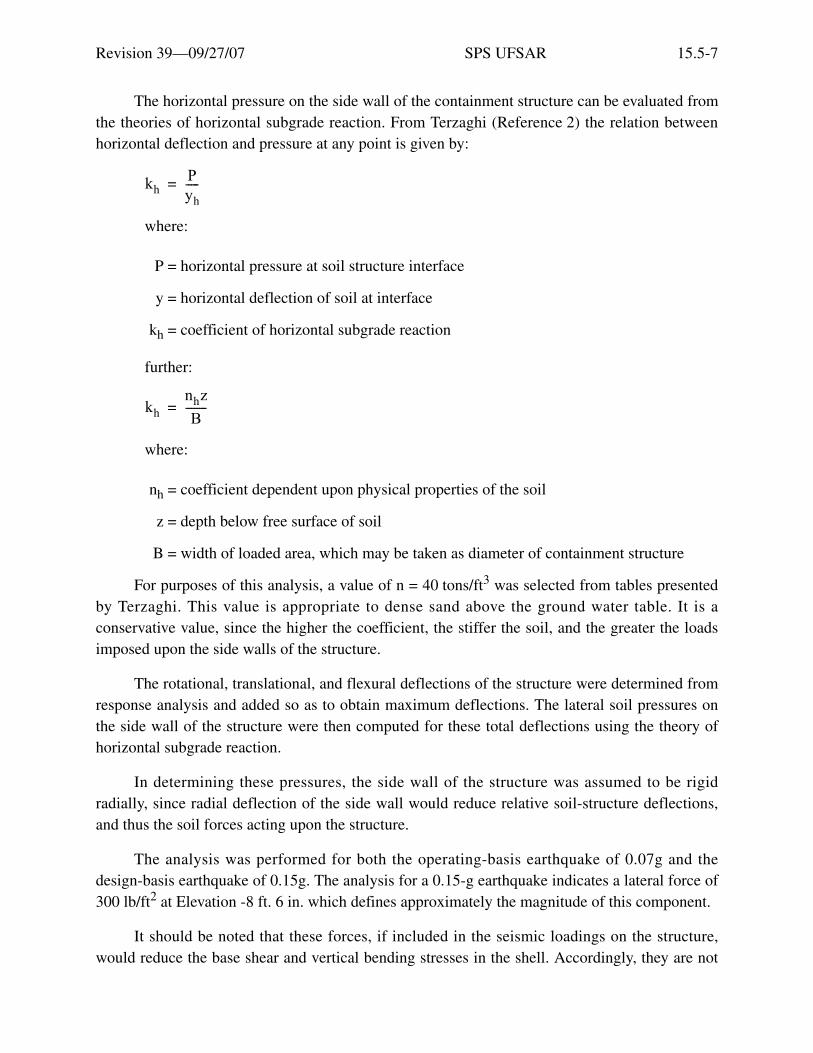
Revision 39—09/27/07 SPS UFSAR 15.5-7
The horizontal pressure on the side wall of the containment structure can be evaluated fromthe theories of horizontal subgrade reaction. From Terzaghi (Reference 2) the relation betweenhorizontal deflection and pressure at any point is given by:
where:
P = horizontal pressure at soil structure interface
y = horizontal deflection of soil at interface
kh = coefficient of horizontal subgrade reaction
further:
where:
nh = coefficient dependent upon physical properties of the soil
z = depth below free surface of soil
B = width of loaded area, which may be taken as diameter of containment structure
For purposes of this analysis, a value of n = 40 tons/ft3 was selected from tables presentedby Terzaghi. This value is appropriate to dense sand above the ground water table. It is aconservative value, since the higher the coefficient, the stiffer the soil, and the greater the loadsimposed upon the side walls of the structure.
The rotational, translational, and flexural deflections of the structure were determined fromresponse analysis and added so as to obtain maximum deflections. The lateral soil pressures onthe side wall of the structure were then computed for these total deflections using the theory ofhorizontal subgrade reaction.
In determining these pressures, the side wall of the structure was assumed to be rigidradially, since radial deflection of the side wall would reduce relative soil-structure deflections,and thus the soil forces acting upon the structure.
The analysis was performed for both the operating-basis earthquake of 0.07g and thedesign-basis earthquake of 0.15g. The analysis for a 0.15-g earthquake indicates a lateral force of300 lb/ft2 at Elevation -8 ft. 6 in. which defines approximately the magnitude of this component.
It should be noted that these forces, if included in the seismic loadings on the structure,would reduce the base shear and vertical bending stresses in the shell. Accordingly, they are not
khPyh-----=
khnhzB
--------=

Revision 39—09/27/07 SPS UFSAR 15.5-8
included when computing such stresses in the shell and thereby contribute to the conservation ofthe design.
Rocking motion of the containment structure was considered in the determination of thenatural frequency, the distribution of inertia forces, and in the amplitudes of motions.
The containment wales supporting the cofferdam structure do not affect consideration ofhorizontal pressure under seismic loading on the containment wall.
Four circular concrete wales originally supported the sheet steel cofferdam in which thecontainment structure is founded. The top wale, Wale A, has been partially removed at severalpoints to permit completion of adjacent structures; in this condition it does not impose anyrestraint on the containment structure. The bottom wale, Wale D, is in the lower plane of thecontainment mat and below the plane of the wall, and offers no restraint. Wale C extends from aheight of 4 ft. to 8 ft. above the base of the wall. Wale B extends from a height of 17 ft. 6 in. to21 ft. 6 in. above the base of the wall. These two wales are approximately 3 ft. 9 in. from thecontainment wall, and the space between the wales and wall is backfilled with pervious fill. Underseismic loading, the distribution of the lateral earth pressure through the cofferdam wales wouldnot have any different effect than if these pressures were applied directly to the structure.
15.5.1.5 Static Analysis
The containment structure was analyzed and designed for all loading conditions combinedwith load factors as outlined in Section 15.5.1.2. The forces, shears, and moments in the structuralshell were obtained from a computer program based on Numerical Analysis of UnsymmetricalBending of Shells of Revolution, by B. Budiansky and P. P. Radkowski, published in the AmericanInstitute of Aeronautics and Astronautics Journal, dated August 1963.
Forces, moments, and shears in the base slab were obtained from a Stone & Webstercomputer program, Flat Circular Mat Foundations for Nuclear Secondary ContainmentStructures. The program analyzes a flat circular plate supported on an elastic foundation andcomputes the discontinuity stresses at the junction of the mat and cylinder, and the soil bearingspressure.
Discontinuity stresses, shears, and moments at the junction of the cylinder and mat weredetermined using an analogy to the Hardy Cross method for distributing fixed-end moments incontinuous frames. The theoretical fixed-end moments obtained from the shell and mat computeranalysis were balanced in proportion to the relative stiffness of the mat and cylinder.
An independent, manual computation, based on Theory of Plates and Shells, byS. Timoshenko, at a few selected points produces forces, shears, and moments substantially thesame as those produced by the computer programs for the shell and the mat.

Revision 39—09/27/07 SPS UFSAR 15.5-9
The containment shell program used to derive stresses in the shell assumes an isotropicmaterial. The program does not include considerations of temperature gradients due to the thermalloadings across the containment wall.
To compute maximum stresses due to the thermal load, six general strain equations werederived, one equation for each of the four principal areas of reinforcing steel and one for eachmajor axis of the steel liner. These equations relate strain to position, temperature, and incidentstress for each item considered. To solve these general strain equations, six additional equationswere used: four equations for strain compatibility, which equate radial and longitudinal strains,and two equations for load equilibrium. The solution of these equations for incident conditionsgives the stress in each of the principal areas of reinforcing steel and the stress on the steel liner.
These equations permit the thermal stresses to be considered separately withoutmodification of the major shell program.
The thermal operating load in the containment concrete wall, combined with incidentcondition loadings, produces a stress difference of approximately 6000 psi between thereinforcing steel adjacent to the inside face of the wall and the reinforcing steel adjacent to theoutside face of the wall. This difference exists in both the longitudinal steel and the hoopreinforcing steel.
To permit the addition of these stresses to those obtained from the containment shellprogram, without exceeding the maximum, the containment shell program stresses are limited to3000 psi below the maximum allowable design stress. This approach is considered extremelyconservative since it limits the design stress in the interior layers of reinforcing steel toapproximately 6000 psi, less than the maximum allowable design stress permitted on the exteriorlayers of reinforcing steel.
Structural failure cannot occur, however, until the interior reinforcing steel exceeds yield.Up to that point plastic yielding of the outside reinforcing would be controlled by the elasticbehavior of the interior steel.
In the solution of the general strain equations, the effect of the concrete has been ignored,since it is assumed to be cracked and incapable of carrying any of the tensile loads considered.The dead load of the concrete is also ignored, as this was found to have little effect on the hoopstresses. This assumption also provides a more conservative result.
The loads exerted on the concrete shell by the thermal effects of the exposed steel liner wereobtained from the calculations discussed above. The equivalent pressure, p, equals the hoop stress,f, in the steel liner multiplied by the liner thickness, t, and divided by the radius of the liner, r. Thecomputed equivalent pressure associated with 1.5 times incident pressure equals 5.45 psi.
Stiffness factors were used to distribute computed fixed-end moments derived from ananalysis of the containment cylindrical wall, considered as a shell with a fixed-end moment, and

Revision 39—09/27/07 SPS UFSAR 15.5-10
from an analysis of the containment mat, considered as a flat circular plate with uniformfixed-edge moment.
Stiffness factors for the cylinders were computed from formulas given in Raymond J.Roark’s book, Formulas for Stress and Strain, for long, thin-walled cylinders. Stiffener factors forthe mat were computed from formulas for circular flat plates with uniform edge moment, from thesame source.
Variation of the modulus of elasticity of the concrete to differentiate between uncracked andcracked concrete was not considered in determining the stiffness factors chosen.
Use of such a variable would modify the distribution of the moments and shear forces tosome degree, but it is not believed that this would significantly affect the accuracy of the results.The safety factor inherent in the present design would accommodate such small variations.
The actual distribution of the moments and forces at the junction of the wall and mat are afunction of the relative stiffness of each member. This is determined by the design approach used.Provided the total forces are distributed between the two areas under consideration, differences ofdistribution due to theoretical variations of the theoretical value of Young’s Modulus for concreteare not considered likely to improve the results beyond the accuracy obtained with theassumptions already used.
The methods for computing soil pressures under the mat were based upon an analogy toE. P. Popov’s Method of Successive Approximations for Beams on an Elastic Foundation,published in the Proceedings of the ASCE, Separate No. 18, dated May 1950. The programcomputes the deflection at the center of the mat relative to a point on the mat at the intersection ofthe center line of the containment shell walls. The elastic curve of the mat deflection is assumed tobe parabolic between these two points. Multiplying the deflection by the subgrade springconstant, the program then provides a parabolic soil pressure curve, which is combined with therectangular soil pressure curves to provide final soil pressures under the mat. The subgrade springconstant is derived from Professor R. V. Whitman’s formula:
where:
k = Spring constant
G = Shear modulus of subgrade material
R = Radius of mat
U = Poisson’s ratio of subgrade material
While the subgrade reaction varies with depth, a single typical value for the reaction wasused which is representative of the zone at the level being considered. The shear modulus was
k 4Gπ 1 U–( )R--------------------------=

Revision 39—09/27/07 SPS UFSAR 15.5-11
computed using a formula developed by Hardin and Black (Reference 3) from observed soilsamples, and substantiated by dynamic triaxial tests of the soil. The stiffness of the soil was alsobased on work by G. N. Bycroft which is referred to in the Section 15.5.1.4.
A variable soil pressure conforming to the deformation of the mat was used in determiningthe stresses in the structure.
Maximum wind velocity associated with a tornado is given as 360 mph. This velocity wasconverted to an equivalent pressure using the formula P =.00256V2, where P = equivalentpressure, lb/ft2 and V = wind velocity, mph. Wind pressure was distributed over the containmentdome in accordance with the methods given in Wind Stresses in Domes, by P. Gondikas andM. G. Salvadori, published in ASCE proceedings No. 2616, dated October 1960.
Wind pressure was distributed over the containment cylindrical shell in accordance with themethods given in Wind Forces on Structures, by T. W. Singell, published in ASCE proceedingsNo. 1710, dated July 1958.
Tornado wind loads were combined with other loads as described in Section 15.5.1.2.
An analysis of the containment structure indicated that resulting membrane stresses due totornado wind loading in the dome reinforcing are less than 5000 psi, and that discontinuitystresses at the junction of the dome and cylinder are somewhat less.
The wind loading on the cylindrical shell creates bending, direct and shear stresses. Thebending and direct stresses in the horizontal reinforcing equal 16,000 psi.
An investigation of overturning due to wind shows that the resultant (DL + wind) fallswithin the Kern point radius of the cylinder, indicating that the vertical reinforcing will not besubject to tensile forces from this load.
Containment torsional loadings from wind were considered negligible, in view of the idealshape of the containment when considered as a torsion resistant shell supplemented by thediagonal reinforcing throughout the walls provided to resist earthquake loads.
The Stone & Webster computer programs for the reactor containment base slab, cylindricalwall, and dome use a constant Young’s Modulus of Elasticity and Poisson’s Ratio. No attempt wasmade to assign varying numerical values to these factors to differentiate between the relativeamount of cracking in different parts of the structure.
The output of the mat program furnishes the following information:
1. Radial and tangential bending moments and vertical shear at five-foot intervals alonghorizontal radii from the center of the mat, spaced at 30-degree intervals.
2. Discontinuity stresses at the junction of the mat and cylinder.
3. Soil pressure.

Revision 39—09/27/07 SPS UFSAR 15.5-12
The output of the shell program furnished forces, shears, and moments at 1-foot intervals inthe height of the cylindrical wall, and at one-degree intervals in the height of the dome. Similarinformation is furnished at each of 16 equidistant points on the circumference of the vessel at eachlevel considered.
Scaled load plots obtained from the computer programs for moment, shear, deflection,longitudinal force, and hoop tension are shown in Figure 15.5-2 for each of three design loadconditions. The fourth design load condition did not govern design and is not represented.
The following assumptions were made:
a. The dead and live structural loads are included in all three of the design load cases.
b. Pressure load, factored and unfactored, is the dominant load condition.
c. Wind loading replaces earthquake loads where wind loads exceed earthquake loads.
d. Tornado loads are included under the general category of wind loads discussed above.
e. Buoyant water loads as discussed in Section 15.5.1.3 are substantially less than deadloads.
f. Earthquake loads, both for the operating-basis earthquake and the design-basisearthquake, are included in the analysis.
g. Thermal load from the liner is converted into an equivalent pressure and added to theincident pressure load when computing moments, shear, and tension associated withthe design-basis accident.
h. Thermal load from the concrete is discussed in Section 15.5.1.5. Stresses resultingfrom this load are combined with incident pressure load stresses.
15.5.1.6 Reinforcing Steel Arrangement
The foundation mat of the containment structure is reinforced with both top and bottomlayers of reinforcing. Bottom mat reinforcing is placed in a rectangular grid pattern with layers at90 degrees to each other. Reinforcing for the top of the mat consists of concentric circular barscombined with radial bars. The reinforcement pattern for the top of the mat is arranged to permitmaintaining a uniform spacing of the vertical wall rebars that extend into the mat. Splices inadjacent parallel rebar in the mat are in general not less than 4 feet apart.
Hoop tension in the cylinder wall is resisted by horizontal bars located near both the outerand inner surfaces of the wall. All horizontal circumferential bars, including those in the dome,have their joints staggered at a minimum of 3 feet apart.
Longitudinal tension in the cylinder wall is resisted by two rows of vertical bars, one nearthe interior face and the other near the exterior face of the wall. Vertical bars are placed in groups

Revision 39—09/27/07 SPS UFSAR 15.5-13
of 20 bars of equal length. These are arranged so that no adjacent group in the same or oppositeface of the wall has splices closer than 6 feet vertically.
See Section 15.5.2.3 for the description of the splicing scheme used for the ReactorPressure Vessel Head Replacement Project.
The dome reinforcing consists of layers of rebar placed radially extending from the verticalreinforcing of the cylindrical wall and horizontal layers of circumferential hoop bars. Layers arelocated near both the inner and outer faces of the concrete. The radial pattern of the reinforcingsteel terminating in the containment dome results in a high degree of redundancy of reinforcingsteel in the dome. Bars are terminated beyond a point where there is more than twice the amountof steel required for design purposes. The rate of convergence of these bars, and low-stressrequirements dictated by the arrangement, produces a low bond stress. In a limited number ofcases where bars are terminated close to the center of the dome, anchorage stresses are morecritical, and bars are hooked to provide the required anchorage. Near the crown, the rebars arewelded to a concentric ring cast in the concrete.
Radial shear loads generated by internal pressure resulting from the design-basis accidentare resisted by rebars inclined at 45 degrees with the horizontal and extending between thesurfaces of both the vertical reinforcing closest to the interior and exterior faces of cylinder wall.This radial shear will vary from a maximum at the base of the wall where the foundation matrestrains the independent movement of the wall to zero at some level above the mat. Anchoragebond stresses in these shear bars is kept below allowable stress levels to minimize potentialcracking of the concrete. In addition, sufficient longitudinal and circumferential reinforcing iscarried to the base of the wall to carry all potential loads without assistance from the radial shearreinforcing.
The tangential shears resulting from the earthquake loading are resisted by rebars inclined atapproximately 45 degrees in each direction, in the plane of the wall parallel to the mainreinforcing steel.
Minimum concrete cover for all principal reinforcing steel of the containment structureexceeds the requirements of ACI 318, Paragraph 808(d), which states, “Concrete protection forreinforcement shall in all cases be at least equal to the diameter of the bars.” The largest andprincipal reinforcing bar is No. 18, which requires a minimum cover of only 2-3/8 inches by thecode.

Revision 39—09/27/07 SPS UFSAR 15.5-14
15.5.1.7 Penetration Design
Penetration through the containment structure is divided into one of the following threecategories:
1. Pipe penetrations nine inches in diameter or less.
No special structural reinforcing is provided for penetrations nine inches in diameter or less.Penetrations in this category are located to avoid interference with the reinforcing steel.
2. Pipe penetrations greater than nine inches and up to 3 ft. 6 in. in diameter.
For penetrations greater than nine inches, and up to and including 3 ft. 6 in. diameter,supplementary reinforcement is provided in amount and distribution such that arearequirements for reinforcement are adequately satisfied.
At all these size penetrations, reinforcing steel interrupted by the openings is terminated ateach side of the opening. Supplementary reinforcing was placed parallel to the interruptedbars to provide bar continuity. Horizontal, diagonal, and vertical bars were used to effectivelyframe the opening. The total area of reinforcement provided in any plane is not less thantwice the area of steel interrupted or cut by the opening, with half of this placed on each sideof the opening.
Additional reinforcing around these openings is not less than 20 feet in length, and ofsufficient length to develop the full ultimate strength of the bar in ultimate bond stress toconform to the requirements of ACI 318, Section 1801(C 2). Horizontal bars are consideredas top bars for this purpose.
3. Openings larger than 3 ft. 6 in. in diameter.
The two openings in this category are the 7 ft. 0 in.-diameter personnel access hatch and the14 ft. 6 in.-diameter equipment access hatch. Details of the additional reinforcementprovided around the equipment access hatch and personnel access hatch are shown inFigures 15.5-3 through 15.5-6, inclusive.
These penetrations are analyzed by means of a computer program (Reference 4). Thisprogram analyzes a ring beam based on the method of virtual work. The program assumes the ringbeam to be isolated from the containment shell and loaded in two planes. The analysis includesthe effect of the stiffened ring and the moments introduced by transferring external loads from theshell at the perimeter of the ring to the center line of the beam.
The ring beams are designed to resist biaxial bending moments, axial tension, torsion, andbiaxial shear resulting from loading criteria listed in Section 15.5.1.2. The biaxial bendingmoments and axial tension are assumed to be resisted by the reinforcing bars only, the concretebeing neglected. The torsional and biaxial shear stresses are assumed to be resisted entirely bybinders placed radially around the penetrations. Torsion is computed by the formulas for torsionin a rectangular beam. The principal circumferential and meridional reinforcing is extended to the

Revision 39—09/27/07 SPS UFSAR 15.5-15
inner face of the ring beam and bent at right angles, hereby providing additional shear resistance,the availability of which is considered in the design.
The normal pattern of membrane stress in the cylinder wall is interrupted in the areaadjacent to the stiffened openings. This redistribution of stress was investigated by means of acomputer program, based upon a paper by B. Budiansky and P. Radkowski (Reference 5). For thisinvestigation, a flat circular plate with a radius equal to three times the distance from the center ofthe opening to the outside face of the stiffening ring beam was used to establish the stress pattern.The movement of both the stiffened ring and the adjacent shell was compared to determine ifsignificant discontinuity stresses were present. Extra reinforcement was added to regions ofmarked deviation from the normal pattern to keep the discontinuity effects to the level at whichthey can be considered negligible. The gross concrete area of the ring section was used todetermine the section stiffness and rigidity.
15.5.1.8 Steel Liner and Penetrations
The containment structure has an inside diameter of 126 ft. 0 in., and an interior verticalheight of 185 ft. 1 in., measured from the top of the foundation mat to the center of the dome. Thecylindrical steel wall liner is 3/8 inch thick, the hemispherical dome liner plate is 0.50 inch thick,and the flat base liner is 0.25 inch and 0.75 inch thick.
See Section 15.5.2.2 for the description of the restoration of the steel liner for the ReactorPressure Vessel Head Replacement Project.
The top of the containment dome at Surry has a 39-inch penetration that was used duringconstruction. This penetration is sealed by a welded plug on the liner side and a bolted plate on theouter end, and is filled with sandbags.
The steel lining is attached to and supported by the concrete; the liner functions primarily asa gastight membrane. The steel wall and dome liner are protected from potential interior missilesby interior concrete shield walls. CRDM missile protection is provided by a concrete shield onUnit 1 and a steel shield on Unit 2. The base liner is protected by a 1.50- to 2-foot-thick concretemat, except in two areas where 0.75-inch-thick liner plate is used beneath the reactor vessel incoreinstrumentation, and at a drainage trench where floor grating provides additional protection.
The steel liner is designed to withstand the effects of all temperature, earthquake, andpressure loads, including the effect of the subatmospheric operating pressure.
The liner stress limits and their associated strains are limited to the stress criteria given inParagraph N-1314 of Section III of the ASME Boiler and Pressure Vessel Code for nuclearvessels, and to basic primary stress levels taken from Table N-421 of that Code. The liner materialSA-442-GR60 has a specified NDT that is at least 80°F below the minimum liner operatingtemperature, and considerably more than 120°F below the design-basis accident temperature.Under either of these conditions, the liner material is able to accommodate at least 60% plastic

Revision 39—09/27/07 SPS UFSAR 15.5-16
strain without cracking. A strain of this magnitude is at least 80 times greater than the maximumstrain that will be imposed on the liner.
Reference to a generalized fracture analysis diagram shows that the “Crack ArrestTemperature” (CAT) curve crosses the NDT +80°F line at approximately 60% of the spanbetween the “Fracture Temperature Elastic” (FTE) and the “Fracture Temperature Plastic” (FTP)ordinates, indicating that the steel can be strained to 60% of the required strain to fracture withoutcracking, even in the presence of large flaws.
To demonstrate that this plate material can accommodate plastic strains of this magnitudewhen biaxially stressed, tests were conducted on samples of 3/8-inch-thick plate of identicalspecification to the steel to be used in this containment liner, at a temperature of 90°F above theNDT of the steel. In these tests, the plate samples were each laid across a 23-inch-diameter ring,and a 3-5/8-inch-diameter mandrel was forced into the plate at the center line of the ring. In allcases, the mandrel deformed the plate by an amount in excess of 4 inches before shearing through.
The design-basis earthquake can be expected to produce tremors to the extent of not morethan 8 to 10 cycles, and the operating-basis earthquake not more than 4 to 5 cycles.
Operating pressure variations from 9.5 psia to 14.7 psia can be expected to occur not morethan 150 times during the lifetime of the unit, since personnel access is permitted undersubatmospheric conditions. Temperature variations from 70°F to 105°F resulting from seasonalswings and shutdowns of the unit can be expected to occur not more than 600 times during thelifetime of the unit.
The containment liner is designed for 1500 cycles of operating pressure variations,6000 cycles of temperature variation, and 20 cycles of design-basis earthquake, all simultaneouslyapplied.
The containment liner is also designed for one cycle of design-basis accident pressure, onecycle of design-basis accident temperature, and ten cycles of design-basis earthquake, allconsidered simultaneously applied.
The containment liner is designed, within allowable working stresses, to withstand avacuum increase of not less than 1.5 psi. The shell and dome plate liner is capable of withstandingan internal pressure of 3 psia, and the bottom mat liner is capable of withstanding an internalpressure of 8 psia, with reference to standard atmospheric conditions outside the containment.
The change in barometric pressure due to tornadoes is not expected to exceed 3 psig, andthe change due to maximum hurricane will be approximately 1.1 psig. These pressure changeswill result in a decrease in the atmospheric pressure, which will decrease the differential betweenatmospheric pressure and the containment structure ambient pressure, thereby decreasing thepotential for stresses in the containment.
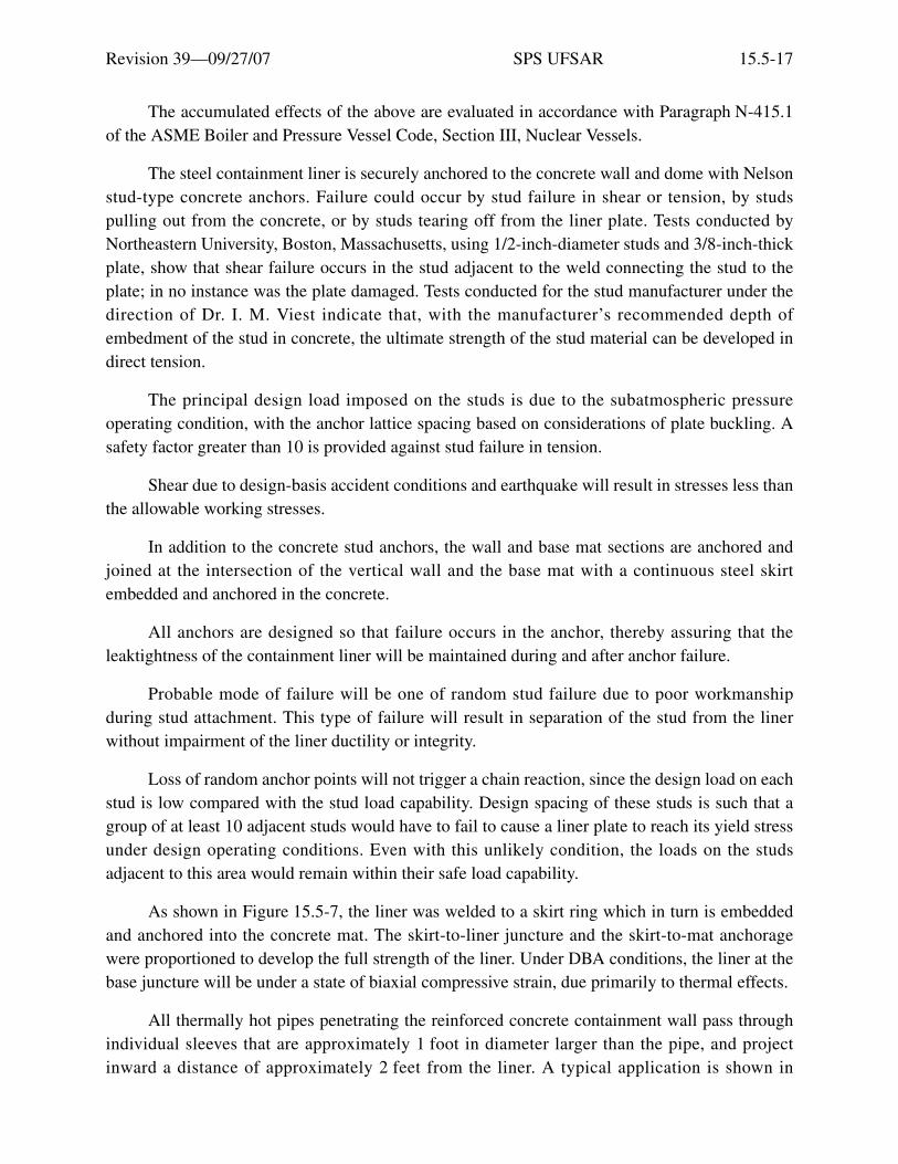
Revision 39—09/27/07 SPS UFSAR 15.5-17
The accumulated effects of the above are evaluated in accordance with Paragraph N-415.1of the ASME Boiler and Pressure Vessel Code, Section III, Nuclear Vessels.
The steel containment liner is securely anchored to the concrete wall and dome with Nelsonstud-type concrete anchors. Failure could occur by stud failure in shear or tension, by studspulling out from the concrete, or by studs tearing off from the liner plate. Tests conducted byNortheastern University, Boston, Massachusetts, using 1/2-inch-diameter studs and 3/8-inch-thickplate, show that shear failure occurs in the stud adjacent to the weld connecting the stud to theplate; in no instance was the plate damaged. Tests conducted for the stud manufacturer under thedirection of Dr. I. M. Viest indicate that, with the manufacturer’s recommended depth ofembedment of the stud in concrete, the ultimate strength of the stud material can be developed indirect tension.
The principal design load imposed on the studs is due to the subatmospheric pressureoperating condition, with the anchor lattice spacing based on considerations of plate buckling. Asafety factor greater than 10 is provided against stud failure in tension.
Shear due to design-basis accident conditions and earthquake will result in stresses less thanthe allowable working stresses.
In addition to the concrete stud anchors, the wall and base mat sections are anchored andjoined at the intersection of the vertical wall and the base mat with a continuous steel skirtembedded and anchored in the concrete.
All anchors are designed so that failure occurs in the anchor, thereby assuring that theleaktightness of the containment liner will be maintained during and after anchor failure.
Probable mode of failure will be one of random stud failure due to poor workmanshipduring stud attachment. This type of failure will result in separation of the stud from the linerwithout impairment of the liner ductility or integrity.
Loss of random anchor points will not trigger a chain reaction, since the design load on eachstud is low compared with the stud load capability. Design spacing of these studs is such that agroup of at least 10 adjacent studs would have to fail to cause a liner plate to reach its yield stressunder design operating conditions. Even with this unlikely condition, the loads on the studsadjacent to this area would remain within their safe load capability.
As shown in Figure 15.5-7, the liner was welded to a skirt ring which in turn is embeddedand anchored into the concrete mat. The skirt-to-liner juncture and the skirt-to-mat anchoragewere proportioned to develop the full strength of the liner. Under DBA conditions, the liner at thebase juncture will be under a state of biaxial compressive strain, due primarily to thermal effects.
All thermally hot pipes penetrating the reinforced concrete containment wall pass throughindividual sleeves that are approximately 1 foot in diameter larger than the pipe, and projectinward a distance of approximately 2 feet from the liner. A typical application is shown in

Revision 39—09/27/07 SPS UFSAR 15.5-18
Figure 15.5-10. The pipe is welded to a thick cap that is an integral part of the end of thepenetration sleeve.
Each penetration sleeve with a thermally hot pipe penetration is equipped with twowater-cooled heat exchangers to limit the temperature of the liner and the concrete in contact withthe sleeve. One heat exchanger is located inside the sleeve encompassing its length (inner unit);the other is located outside the penetration sleeve in proximity to the liner. Either of the heatexchangers will provide adequate cooling for the penetration if the other is out of service. Theassociated component cooling water system has two independent lines. One line circulates waterthrough the outer unit; the other circulates water through the inner unit. The inner unit limits theradial heat flow resulting from convection and thermal radiation from the thermally hot pipepenetration, to keep the temperature of the concrete in contact with the sleeve within allowablelimits. In addition, the inner unit controls the longitudinal heat flow resulting from conductionfrom the same heat source, thus limiting the temperature of the liner and temperature gradientalong the sleeve to keep the resulting thermal stresses in the liner and sleeve within the limits setforth in Section III of the ASME Pressure Vessel Code. The outer unit also limits the longitudinalheat flow, providing independent thermal protection of the penetration sleeve and liner.
The circumferential groove in the attachment plate, between the sleeve and penetration withits outside threaded connection, serves as a test chamber for the testing of the welds joining theattachment plate and penetration.
All penetrations are anchored in the reinforced concrete containment wall. The anchorstrength is equal to the full yield strength of the pipe with regard to torsion, bending, and shear,and to the maximum possible pipe jet reaction. All stresses induced in the liner by thesecombinations of loadings are only those reflected by the resulting distortions in the reinforcedconcrete containment wall, and are minor in intensity. So, loads will not be imposed on the liner,thereby preserving its integrity.
All highly stressed insert plates at penetrations and equipment supports that are welded intothe liner to transfer loads into the concrete have been ultrasonically tested to check for possiblelaminations. Tests were conducted on all plates where analysis showed a higher than averagestress field, although all such plates are stressed well below the allowable limits for the materials.These tests show that no faults exist in the insert plates.
The pipes anchored to the containment penetrations between containment isolation valvesconstitute an extension of the containment, and are designed in accordance with the USA StandardCode for Pressure Piping - Power Piping, USAS B31.1.0-1967, with respect to materials andallowable stress. Analyses of stresses due to thermal expansion and shock loadings fromearthquake, pipe jet reaction, and other causes were made using established digital computercalculation techniques.
In order to determine the loading combinations that act on a penetration, the pipe linepassing through the penetration sleeve was assumed to have failed transversely at several
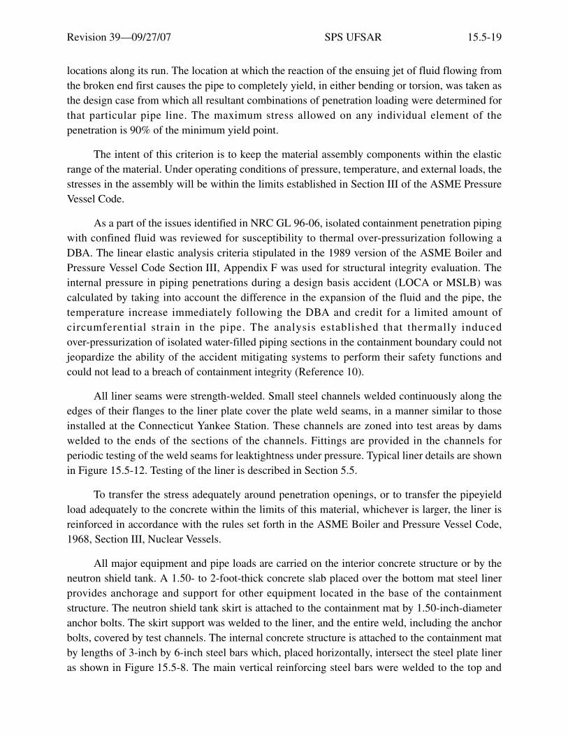
Revision 39—09/27/07 SPS UFSAR 15.5-19
locations along its run. The location at which the reaction of the ensuing jet of fluid flowing fromthe broken end first causes the pipe to completely yield, in either bending or torsion, was taken asthe design case from which all resultant combinations of penetration loading were determined forthat particular pipe line. The maximum stress allowed on any individual element of thepenetration is 90% of the minimum yield point.
The intent of this criterion is to keep the material assembly components within the elasticrange of the material. Under operating conditions of pressure, temperature, and external loads, thestresses in the assembly will be within the limits established in Section III of the ASME PressureVessel Code.
As a part of the issues identified in NRC GL 96-06, isolated containment penetration pipingwith confined fluid was reviewed for susceptibility to thermal over-pressurization following aDBA. The linear elastic analysis criteria stipulated in the 1989 version of the ASME Boiler andPressure Vessel Code Section III, Appendix F was used for structural integrity evaluation. Theinternal pressure in piping penetrations during a design basis accident (LOCA or MSLB) wascalculated by taking into account the difference in the expansion of the fluid and the pipe, thetemperature increase immediately following the DBA and credit for a limited amount ofcircumferential strain in the pipe. The analysis established that thermally inducedover-pressurization of isolated water-filled piping sections in the containment boundary could notjeopardize the ability of the accident mitigating systems to perform their safety functions andcould not lead to a breach of containment integrity (Reference 10).
All liner seams were strength-welded. Small steel channels welded continuously along theedges of their flanges to the liner plate cover the plate weld seams, in a manner similar to thoseinstalled at the Connecticut Yankee Station. These channels are zoned into test areas by damswelded to the ends of the sections of the channels. Fittings are provided in the channels forperiodic testing of the weld seams for leaktightness under pressure. Typical liner details are shownin Figure 15.5-12. Testing of the liner is described in Section 5.5.
To transfer the stress adequately around penetration openings, or to transfer the pipeyieldload adequately to the concrete within the limits of this material, whichever is larger, the liner isreinforced in accordance with the rules set forth in the ASME Boiler and Pressure Vessel Code,1968, Section III, Nuclear Vessels.
All major equipment and pipe loads are carried on the interior concrete structure or by theneutron shield tank. A 1.50- to 2-foot-thick concrete slab placed over the bottom mat steel linerprovides anchorage and support for other equipment located in the base of the containmentstructure. The neutron shield tank skirt is attached to the containment mat by 1.50-inch-diameteranchor bolts. The skirt support was welded to the liner, and the entire weld, including the anchorbolts, covered by test channels. The internal concrete structure is attached to the containment matby lengths of 3-inch by 6-inch steel bars which, placed horizontally, intersect the steel plate lineras shown in Figure 15.5-8. The main vertical reinforcing steel bars were welded to the top and

Revision 39—09/27/07 SPS UFSAR 15.5-20
bottom faces of these bars, thus providing bar continuity without creating multiple penetrationsthrough the liner.
The 1.50-foot-thick concrete slab is anchored through the steel liner plate in a similarmanner using 7-inch by 0.50-inch bars, as shown in Figure 15.5-8. These bars, termed bridgingbars, form an integral part of the steel liner, and conform to the material and workmanshipspecifications of the steel liner. All welded joints are covered by test channels and tested as allother liner plate joints.
Access to the containment structure is provided by a 7 ft. 0 in. i.d. personnel hatch and a14 ft. 6 in. i.d. equipment hatch. Other smaller containment structure penetrations include hot andcold pipes, main steam and feedwater pipes, fuel transfer tube, and electrical conductors.
Electrical conductors penetrating the containment structure range in size from No. 16 AWGthermocouple leads to 1-inch-diameter solid copper rods for 4160V power circuits. Eachpenetration group passes through 8-inch-diameter steel sleeves. The sleeves were welded into thecontainment liner with a test channel around the weld for periodic leak testing, as shown inFigure 15.5-9 (Amphenol electrical penetration depicted).
The basic Amphenol electrical penetration consists of an eight-inch steel tube withbolted-on flanges, through which pass the sealed conductors. The hermetically sealed connectors,as shown in Figure 15.5-9, were bench-tested for leaktightness.
Each flange is held tightly in place with eight bolts that draw the flange against a hightemperature sealing ring and a backing plate welded to the sleeve. Each flange is tapped for leaktesting. A make-up method is used to determine the penetration leakage by applying a testpressure equal to greater than containment design pressure (45 psig) between the o-ring seals. Anelectrical connector may be replaced, if necessary, without welding or cutting the containmentliner or sleeve.
The design and qualifications of the Amphenol electrical mating connectors are based uponthe requirements of military specification number MIL-C-5015. Connector design is such thatsilastic components are provided in the connector to feed through the interface. This type ofinterface has been proven adequate to meet the environmental requirements of MIL-C-5015.Additional capability to withstand elevated temperatures is provided in the material used for thesealing members.
The original tests conducted at the Amphenol’s shop consisted of the following:
Connectors installed in the flanges normally operate at ambient conditions of 105°F and9.75 psia, and were tested for leak rate and tagged for integrity before shipment to the job. Atest facility was set up by the manufacturer suitable for 50 psig, with provisions forthermocycling from 32° to 300°F. A thermocycle run of at least three cycles was made onone of each type flange. A time interval of 30 minutes was allowed between the

Revision 39—09/27/07 SPS UFSAR 15.5-21
thermocycles. The leak rate test after thermocycling was made at 50 psig and 300°F. Eachcompleted flange had a leak rate of less than 1 × 10⁻⁶ cc/sec per assembled flange. Allflanges were leak tested at 50 psig and 300°F. Helium gas was used in the test facility.
For the Amphenol triaxial cable penetrations a more detailed procedure for the thermocycletest was followed in shop test:
The type sample consisted of a containment side flange disk with hermetic assemblieswelded in place. A thermocouple was installed to monitor disk temperature. The disk wasstabilized at 32°F and then placed in an oven heated previously to 280°F. On entrance of thedisk, the oven temperature was reduced, straight line, to 150°F over a 60-minute period. Thedisk was removed and cooled to 100°F, while the oven was reheated to 280°F. The disk wasthen returned to the oven and the oven temperature reduced to 150°F as before. The highestmetal temperature reached during this cycle was recorded and a 50-psig helium leak testwas conducted at this metal temperature for all discs of this type.
Each Amphenol penetration assembly, without external cable mating connectors, was testedin the factory to demonstrate insulation resistance of at least 1000 megohms at 1000V dc. Inaddition, each penetration has passed an overpotential test. After initial installation, eachpenetration with external cables connected was tested at 1000V dc for 5 minutes.
Containment electrical penetrations now in use at the Surry Power Station weremanufactured by either Amphenol Space and Missile Systems, Conax Corporation, orWestinghouse Electric Corporation. Nitrogen pressure is not required for penetration functionalcapability; however, each penetration is capable of being pressurized with nitrogen for leakdetection purposes. RTV-8112, THIOKOL, or POLYSYLFONE are used to provide a tight sealaround conductors.
Amphenol penetration electrical connectors were tested by D. G. O’Brien, Inc. in 1972. Thepurpose of this test was to demonstrate operability during simulated LOCA conditions. Theconnectors passed the test with no less than 34 megohms internal resistance while retainingcomplete electrical continuity. The test had no observable physical effect on the connectorassembly or cable. No connectors are associated with the CONAX or Westinghouse typepenetrations; however, both manufacturer’s have provided data regarding the performance of thematerials used in their penetrations. This information includes thermal performance, radiationresistance, and chemical resistance tests. All data indicate excellent performance characteristicsfor a LOCA environment.

Revision 39—09/27/07 SPS UFSAR 15.5-22
All containment structure piping penetrations consist of a basic containment insert, plusadditional items, as required for the individual services. Two basic types of penetrations are usedfor piping systems:
1. Unsleeved - These penetrations consist of piping installed through the containment wallwithout a sleeve around the outside of the piping. Unsleeved penetrations are used for coldpiping systems (temperature of the fluid in the piping is less than 150°F) when only one pipepasses through the penetration.
2. Sleeved - These penetrations have a sleeve around the outside of the piping. Sleevedpenetrations are used for all multiple piping systems passing through one penetration and forall thermally hot (over 150°F) piping systems, both single and multiple. Typical pipingpenetrations are shown in Figure 15.5-10.
The main steam and feedwater penetrations are provided with adequate space between thepiping and the sleeve for the necessary pipe insulation, and for a pipe coil outside the insulationthrough which component cooling water is circulated. This cooling coil reduces the temperatureof the sleeve and prevents any excessive heating of the concrete in contact with the sleeve. Allwelded seams subjected to containment pressure are leaktested by introducing air through eachtest boss. In addition, the sleeve end is drilled and tapped, as shown in the details, so that anyleakage between pipe wall and sleeve end can be detected during periodic containment leakagetesting.
The liquid and gas pipe penetration assemblies, in nearly all instances, consist of more thanone pipe inside the penetration sleeve. The diameter of the sleeve depends on the number and sizeof the pipes installed in a given penetration. Each of these penetrations was tested with air usingthe same procedure as that used for the steam and feedwater penetrations.
A 20-inch o.d. fuel transfer tube penetration is provided for fuel transfer between therefueling canal in the containment structure and the spent-fuel pool in the fuel building. Thepenetration consists of a 20-inch stainless steel pipe installed inside a 26-inch pipe, as shown indetail in Figure 15.5-10, Sheet 1. The inner pipe acts as the transfer tube, and connects thecontainment refueling canal with the spent-fuel pool. The outer pipe is welded to the containmentliner, and provision is made, by use of a special seal ring, for air leak testing of all welds essentialto the integrity of the penetration. Bellows expansion joints are provided on the outer pipe tocompensate for any differential movement between the two pipes.
The equipment hatch is a 14-ft. 6-in. single closure penetration. The equipment hatch coveris mounted inside the containment structure and is double gasketed with a leakage test tapbetween the o-rings. The equipment hatch cover is provided with a hoist with two pointsuspension and a sliding rail for storage. A positive locking device is furnished to prevent circularswing. The equipment hatch was designed, fabricated, and stamped in accordance with the ASMEBoiler and Pressure Vessel Code, Section III, Class B. A removable concrete tornado missileshield protects the equipment hatch and acts as equivalent shielding.

Revision 39—09/27/07 SPS UFSAR 15.5-23
The equipment hatch opening is analyzed in two basic steps, using the actual space curveshape. In the first step, it is assumed that the pattern of stress concentration at the junction of thecylinder and the ring beam is the same as if the cylinder were of infinite radius and the ring andthe cylinder were in the same plane; that is, the cylinder wall is assumed to be a flat plate. Theforces are imposed on this flat plate at such a distance from the opening that they are notinfluenced by the opening. These forces are membrane meridional (vertical) loads,circumferential (hoop) loads, and tangential shear loads. An outward longitudinal force isdelivered to the inside face of the ring beam by a bearing plate which is welded to the liner plate.This force is caused by incident pressure acting on the hatch.
The first step of analysis is performed by using the Stone & Webster Shell I computerprogram, which is based on general first-order linear plate theory modified by Sanders. Thisprogram is developed from a numerical analysis of shells of revolution as published by BernardBudiansky and Peter Radkowski in the AIAA Journal, Vol. 1, No. 8, August 1963.
In the second step, the ring is isolated and analyzed, taking into account its actual geometry(curved in two planes). The loads imposed on the ring beam have been obtained at the junction ofthe ring and normal shell in the first step, plus the incident pressure loads and temperature effectson the ring surface.
The second step of the analysis is performed by means of the Stone & Webster computerprogram, Reinforcing Opening in a Cylindrical Structure. This program analyses structurescurved in space about two axes. The loads imposed on the ring are the membrane forces at thejuncture of the thickened ring and the normal shell, as obtained from the first step, and a modifiedincident pressure acting on the ring beam and hatch cover.
The analysis of the isolated ring is based on the theory of curved beams, as demonstrated inSeely and Smith, Advanced Mechanics of Materials. Although the theory in this textbook isconfined to the one-dimensional, curved beam, the assumptions set forth are extended to thetwo-dimensional case. These assumptions permit a simplified calculation of the stresses anddeformations.
The ring, loaded in two planes, is statically indeterminate to the sixth degree. The analysisfor the ring in space consists of cutting the ring, imposing six unknown loads at the cut section,and solving for the six unknown forces by equating differential deflections and rotations on eitherside of the cut to zero. The six unknown forces are: direct force, a torsional moment, a transverseshear, a radial shear, and bending moments about two axes. The curvature of the ring is consideredin obtaining the bending moment strains and effects on total strain energy.
An emergency airlock is provided through the equipment hatch for emergency access to thecontainment. The airlock is flanged to the outside of the equipment hatch cover utilizing a doubleo-ring seal, and has an outside diameter of 6 ft 0 in., and a length of 12 ft 8.50 in. A30-inch-diameter door is located at each end of the air lock. The air lock doors, which swingtoward the center of the containment, are interlocked so that one door cannot be operated unless

Revision 39—09/27/07 SPS UFSAR 15.5-24
the other is closed. These are mechanical interlocks, and provisions have been made for deliberateviolation of the interlock by use of a special tool. This tool shall be kept under administrativecontrol.
Each door is equipped with a valve for equalizing the pressure across the door. At no timecan the equalizing valves on both doors be open simultaneously, and in no case can an equalizingvalve be open on one door while the other is operating.
The operations required at each station for engagement or release of the interlocks, foroperation of the equalizing valve, and for opening or closing the door, are accomplished byrotation of a single handwheel. Provisions have been made to allow operation of the outer doorfrom inside the containment and the inner door from outside the containment, in addition to localoperation.
Both doors are designed to withstand the containment test pressure of 52 psig. Each door isalso designed to withstand 8.0 psia pressure in the containment structure with full atmosphericpressure outside. The interior door is provided with an additional securing device to facilitatetesting the air lock to the maximum test pressure when the containment structure is at 8.0 psia.
All shafts penetrating the door or bulkhead have double packing. A blind flangedemergency air port is provided on the air lock outside containment. A light is provided inside theair lock and is powered near the air lock for communication.
A track is provided for emergency air lock removal via a cart. The track consists of twocontinuously supported rails that extend through the equipment hatch barrel onto the platform.Chicago Bridge and Iron Company designed and installed the track inside the equipment hatchbarrel, and Stone & Webster designed the identical mating rails on the platform.
The tornado missile shield outside the containment equipment hatch has been modified toprovide a labyrinth passage to the air lock. The missile shield slabs are fastened to the equipmenthatch platform, which consequently has been modified. The equipment hatch platform hassufficient structural steel to withstand tornado wind loads on the attached missile shields.
The design, fabrication, and testing of the emergency air lock was performed by ChicagoBridge and Iron Company according to the ASME Code Section III, Subsection NE, 1971 Editionthrough the Winter 1972 Addenda. Welder procedures and performance qualifications werecontrolled under ASME Code Section IX.
The personnel hatch is a 7 ft. 0 in. i.d. double closure penetration as shown inFigure 15.5-11. Each closure head is hinged, double gasketed with a leakage test tap between theo-rings. Both doors are interlocked so that in the event one door is open, the other cannot beactuated. Both doors are furnished with a pressure equalizing connection. The equalizing valvesare manually operated by persons entering or leaving the personnel hatch. The personnel hatchwas designed, fabricated and stamped in accordance with the ASME Boiler and Pressure Vessel

Revision 39—09/27/07 SPS UFSAR 15.5-25
Code, Section III, Class B. The personnel hatch is externally protected from tornado missiles byconcrete shield walls and roof.
An 18-inch-diameter manway on the inner door of the personnel airlock is also provided foremergency egress from the containment. A positive locking device prevents inadvertent openingof the emergency manway. Manway position indication is provided in the control room. Alarmindication is also provided in the control room, and on the control panels on either side of thepersonnel airlock inner door, to indicate whenever the manway locking bar is not in the properposition to prevent inadvertent opening of the manway.
Material for the liner and penetrations is carbon steel plates conforming to ASTM A442,Grade 60, which has a specified minimum tensile strength of 60,000 psi, a minimum guaranteedyield strength of 32,000 psi, and a guaranteed minimum elongation of 25% in a standard 2-in.specimen. The liner has sufficient ductility to tolerate local deformation without rupture. Thismaterial has a nil ductility transition temperature of -20°F, which is 80°F below the normalminimum shutdown temperature given in Section 5.4.1.
Steel items, except backing plates and anchors, gas testing channels, equipment hatch bolts,and equipment hatch nuts are made to fine grain practice and normalized. In addition, steel itemsother than the above have passed NDT tests performed in accordance with the following:
1. Material 5/8 inch and thicker was tested by the Drop Weight Test method in accordance withASTM E 208.
2. Material less than 5/8 inch thick was tested by the Drop Weight Tear Test method asdeveloped by the U.S. Naval Research Laboratory (NRL Report 6300).
3. Material 5/8 inch and thicker has an NDT no higher than -20°F.
The liner plates were ordered to conform to standard mill practice with regard to thicknesstolerances. Therefore, the 3/8-inch-thick cylindrical shell liner plate ranges in thickness from0.365 inches to 0.406 inches. The 0.50-inch-thick hemispherical dome liner plate ranges inthickness from 0.490 inches to 0.535 inches, and the 0.25-inch-thick flat base liner plate ranges inthickness from 0.240 inches to 0.285 inches.
Physical and chemical properties of materials used in the construction of the containmentliner, weldability tests, and liner thickness were checked by the Stone & Webster Field QualityControl Organization on a random sampling basis.
All welding procedures and tests required in Section IX of the ASME Boiler and PressureVessel Code for Welding Qualifications were adhered to in the selection of weld rod material,weld rod flux, heat treatment, and qualification of the welding procedures and the performance ofwelding machines and welding operators engaged in the construction of the containment liner.The welding qualification included 180-degree bend tests of weld material. These procedures

Revision 39—09/27/07 SPS UFSAR 15.5-26
ensure that the ductility of welded seams was comparable to the ductility of the containment linerplate material.
Section III of the ASME Boiler and Pressure Vessel Code for Nuclear Vessels was used as aguide in the selection of materials.
Erection of the steel liner followed completion of the concrete mat. The 3/8-inch-thick steelwall liner was erected to approximately Elevation +60 ft. The 0.25-inch-thick mat liner plate wasinstalled on top of the concrete foundation mat during this period. On completion of the wall linerto Elevation +60 ft. and completion of the mat liner, all welds were checked for compliance withthe approved weld inspection and gas test requirements. Work on the liner was then stopped untilthe containment interior concrete structure was completed, the polar crane was erected, and theconcrete containment wall was completed to ground grade (Elevation 26 ft. 6 in.).
The 3/8-inch-thick steel wall liner was erected from Elevation +60 ft. to Elevation +92 ft.6 in., and the containment liner completed with the construction of the 0.50-inch-thick steel domeliner. A-1 welds were inspected and gas-tested for compliance with the weld requirements.
The reinforced concrete wall, above ground grade, was completed, following as closely aspractical the construction of the wall liner.
The reinforced concrete dome was constructed upon completion of the dome liner.
The steel wall liner was braced internally and locally with temporary bracing to preventdistortion during concrete placement. The exterior concrete forms were supported from the placedconcrete and tied to form a tension ring.
Cantilevered steel strongbacks were used in the construction of the concrete dome tosupport the steel dome liner against deformation due to the weight of reinforcing steel formworkand wet concrete. Strongbacks were cantilevered from the completed concrete of the dome.
The containment liner is not a coded pressure vessel, so there was no section of the ASMEBoiler and Pressure Vessel Code for Nuclear Vessels directly applicable to its design andconstruction. However, to ensure that good engineering practices were followed, certain portionsof Section III of the Code were reviewed for suggested guidance as to design and constructionpractices that should be incorporated in the liner specifications. Those sections reviewed forinformation were:
• N-511 Certification of Materials by Vessel Manufacturer
• N-512 Material Identification
• N-513 Examination During Fabrication
• N-514 Repair of Material by Welding

Revision 39—09/27/07 SPS UFSAR 15.5-27
• N-515 Forming Shell Sections and Heads
• N-518 Attachments
• N-519 Cutting Plates and Other Products
• N-521 Welding Processes
• N-522 Welding Qualifications and Weld Records
• N-523 Precautions for Welding
• N-524 Assembly
• N-526 Finished Longitudinal and Circumferential Joints
• N-527 Miscellaneous Welding Requirements
• N-528 Repair of Weld Defects
• N-531 Preheating
• N-541 Modification of Section IX - Welding Procedure Qualification Requirements
• N-611 Inspection, General
• N-612 Qualification of Inspectors, Engineering Specialists, and Inspection Agencies
• N-613 Access for Inspector
• N-614 Inspection of Materials
• N-615 Marking on Plates and Other Material
• N-616 Final Inspection
• N-620 Inspection of Welding
• N-622 Check of Welder and Welding Operator Performance Qualifications
• N-623 Check of Nondestructive Examination Methods
• N-625 Ultrasonic Examination of Welded Joints
• N-626 Magnetic Particle Examination
• N-627 Liquid Penetrant Examination
• N-713 Pneumatic Test
• N-714 Pressure Test Gauges
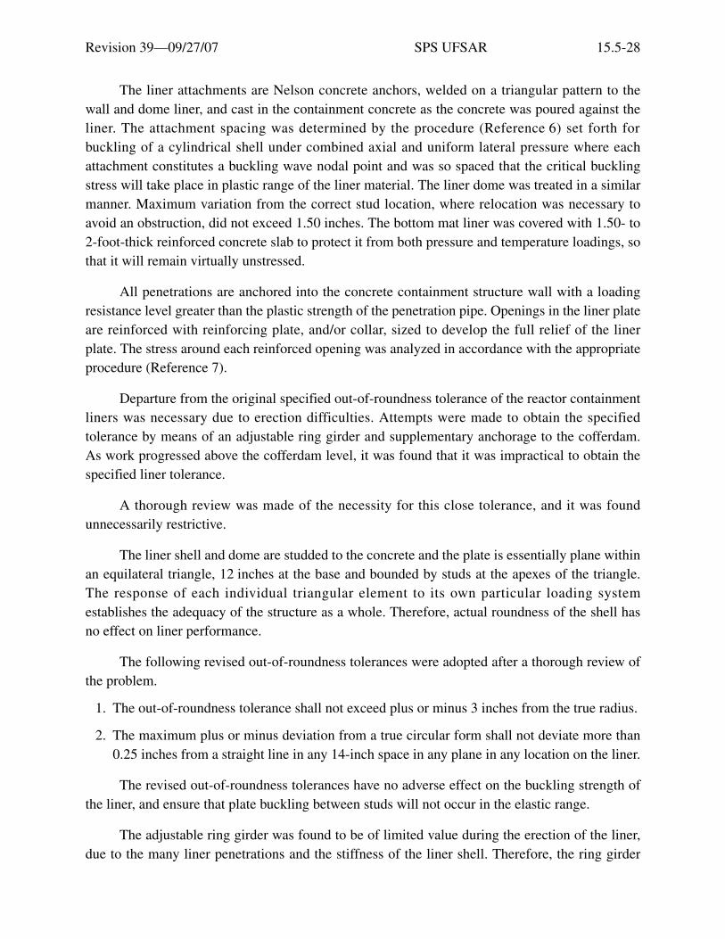
Revision 39—09/27/07 SPS UFSAR 15.5-28
The liner attachments are Nelson concrete anchors, welded on a triangular pattern to thewall and dome liner, and cast in the containment concrete as the concrete was poured against theliner. The attachment spacing was determined by the procedure (Reference 6) set forth forbuckling of a cylindrical shell under combined axial and uniform lateral pressure where eachattachment constitutes a buckling wave nodal point and was so spaced that the critical bucklingstress will take place in plastic range of the liner material. The liner dome was treated in a similarmanner. Maximum variation from the correct stud location, where relocation was necessary toavoid an obstruction, did not exceed 1.50 inches. The bottom mat liner was covered with 1.50- to2-foot-thick reinforced concrete slab to protect it from both pressure and temperature loadings, sothat it will remain virtually unstressed.
All penetrations are anchored into the concrete containment structure wall with a loadingresistance level greater than the plastic strength of the penetration pipe. Openings in the liner plateare reinforced with reinforcing plate, and/or collar, sized to develop the full relief of the linerplate. The stress around each reinforced opening was analyzed in accordance with the appropriateprocedure (Reference 7).
Departure from the original specified out-of-roundness tolerance of the reactor containmentliners was necessary due to erection difficulties. Attempts were made to obtain the specifiedtolerance by means of an adjustable ring girder and supplementary anchorage to the cofferdam.As work progressed above the cofferdam level, it was found that it was impractical to obtain thespecified liner tolerance.
A thorough review was made of the necessity for this close tolerance, and it was foundunnecessarily restrictive.
The liner shell and dome are studded to the concrete and the plate is essentially plane withinan equilateral triangle, 12 inches at the base and bounded by studs at the apexes of the triangle.The response of each individual triangular element to its own particular loading systemestablishes the adequacy of the structure as a whole. Therefore, actual roundness of the shell hasno effect on liner performance.
The following revised out-of-roundness tolerances were adopted after a thorough review ofthe problem.
1. The out-of-roundness tolerance shall not exceed plus or minus 3 inches from the true radius.
2. The maximum plus or minus deviation from a true circular form shall not deviate more than0.25 inches from a straight line in any 14-inch space in any plane in any location on the liner.
The revised out-of-roundness tolerances have no adverse effect on the buckling strength ofthe liner, and ensure that plate buckling between studs will not occur in the elastic range.
The adjustable ring girder was found to be of limited value during the erection of the liner,due to the many liner penetrations and the stiffness of the liner shell. Therefore, the ring girder

Revision 39—09/27/07 SPS UFSAR 15.5-29
was used for rounding the shell only in areas where its application was found advantageous by theliner fabricator.
15.5.1.9 Materials
See Sections 15.5.2.2, 15.5.2.3, and 15.5.2.4 for descriptions of the construction materialsused for the Reactor Pressure Vessel Head Replacement Project.
15.5.1.9.1 Concrete
The description of concrete materials is given in Section 15.3.1.
See Section 15.5.2.4 for the description of the concrete used for the Reactor Pressure VesselHead Replacement Project.
15.5.1.9.2 Porous Concrete
Porous concrete is used under the base mat to provide drainage for the containmentstructure. The type of concrete is formed by the omission of the fine aggregate from a standardstructural concrete mix. The mix was designed to have a 28-day compressive strength greater than1000 psi.
Water porosity tests were performed earlier in an independent laboratory for porousconcrete, using 6-inch by 12-inch cylinders prepared in the laboratory by compacting the materialin three layers with standard tamping rods. A varying number of strokes, ranging from 10 to 40for each layer, were used for different cylinders. After the concrete test cylinders had beenproperly cured, the amount of water that would flow through the 12-inch length of specimenduring a three-minute period with a constant head of 4 inches of water above the top of eachcylinder was determined. Results indicated water porosities of from 28 to 47 gpm/ft2, dependingupon the amount of compaction and resulting density of the cylinders.
The porosity determined by the laboratory tests indicated that the four-inch porous concretelayer under the base mat provides adequate drainage, since the leakage through the membranewaterproofing of the container would be minor. This layer serves as the collection means for theseepage removal system in the mat, described in Section 15.5.1.3.
15.5.1.9.3 Reinforcing Steel
Special large-size reinforcing bars, No. 14 and No. 18, used in the construction of thereactor containment structure, are steel of 50,000 psi minimum yield point, conforming toGrade 40 of the Standard Specification for Deformed Billet-Steel Bars for ConcreteReinforcement, ASTM A615 as modified to meet the following chemical and physicalrequirements:
• Carbon 0.35% maximum
• Manganese 1.25% maximum

Revision 39—09/27/07 SPS UFSAR 15.5-30
• Silicon 0.15 to 0.25%
• Phosphorus 0.05% maximum
• Sulphur 0.05% maximum
• Minimum yield strength 50,000 psi.
• Elongation 16% minimum in a 2-inch test sample
• Tensile strength 70,000 to 90,000 psi
For these special chemistry bars, all ingots were identified and all billets were stamped withidentifying heat numbers. All bundles of bars were tagged with the heat number as they came offthe rolling mill. A special stamp marking was rolled into all bars conforming to this specialchemistry, to identify them as processing the chemical and mechanical qualities specified.
See Section 15.5.2.3 for the description of the reinforcing steel used for the ReactorPressure Vessel Head Replacement Project.
The engineers’ quality assurance inspectors witnessed, on a random basis, the pouring ofthe heats and the physical and chemical tests performed by the fabricator. Bars containinginclusions, or failing to conform to the required chemical and physical requirements, wererejected.
One 12-inch-long test sample was furnished to the engineers from a finished bar from eachheat of the special chemistry rebars, to permit independent verification of physical and chemicalanalysis tests by the engineers.
Test specimens for the special chemistry rebars conformed to Section 10.1.1 ofASTM A615 and were Standard 0.505-inch-diameter specimens with 2-inch gauge length. Rateof loadings was such that the tension-tested sample was brought to the yield point in not less than2 minutes.
For containment structure, reinforcing steel, consisting of No. 11 bars and smaller, is of40,000 psi minimum yield point, conforming to Grade 40 of the Standard Specification forDeformed Billet-Steel for Concrete Reinforcement, ASTM A615.
The reinforcing steel for structures other than the containment structures is described inSection 15.4.3.
15.5.1.9.4 Cadweld Splices
Cadweld reinforcing steel splices, Type “T” full tension splices, as manufactured by EricoProducts, Inc., Cleveland, Ohio, were used to splice 50,000 psi minimum yield point reinforcingbar sizes No. 14 and No. 18. These splices, including the sleeves, develop tensile strengths notless than 90% of the minimum ultimate strength of the reinforcing bar. The average value of two
Revision 39—09/27/07 SPS UFSAR 15.5-31
or more successive splices develop at least the minimum ultimate strength of the rebar.Information for splices other than No. 14 and No. 18 reinforcing bars is given in Section 15.4.3.
See Section 15.5.2.3 for the description of Cadwelds, including operator qualification andtensile testing, used for the Reactor Pressure Vessel Head Replacement Project.
15.5.1.9.5 Waterproofing Membrane
The waterproofing membrane is a flexible polyvinyl chloride sheet having a minimumthickness of 40 mils. Associated adhesives and tapes consist of the membrane manufacturer’srecommended material for the application conditions.
15.5.1.10 Construction Procedures and Practices
After performing the general excavation described in Section 15.4.4, two 149-ft.5.25-in.-diameter cofferdams were constructed, one for each reactor. The cofferdams consist ofinterlocking steel sheet piles supported by a system of heavily reinforced concrete internal ringwales. The top of the sheet piles is at Elevation +10 ft. and tip grade is at Elevation -48 ft. Theinterior of the cofferdams was excavated to approximately Elevation -41 ft. Seepage drains werethen driven through a 12-inch layer of crushed stone placed in the bottom of the excavation, asdescribed in Section 15.5.1.3.
A 2-inch-thick concrete leveling slab was placed over the crushed stone and 40-mil-thickvinyl waterproof membrane placed over this concrete. A 4-inch layer of porous concrete was thenplaced over the membrane to protect the membrane and to serve as an internal drainage system, asdescribed in Section 15.5.1.12.
Porous concrete was also placed around the sides of the cofferdam to fill the space betweenthe cofferdam and the edge of the concrete mat, and to provide a form for the mat concrete. Thewaterproof membrane was extended vertically in this area, and protected by concrete block.
The reinforcing steel, steel bridging bars as described in Section 15.5.1.8, and othermiscellaneous steel inserts required in the containment mat were placed, and the concrete poured.The mat was constructed in six sections.
The 3/8-inch-thick steel wall liner was then erected to Elevation +60 ft on the containmentwall. The steel mat liner plates were installed on top of the concrete mat. All welds were checkedfor compliance with the approved weld inspection and gas test requirements. The containmentinterior concrete structure was then built on the mat liner. On completion of the interior concretestructure, the polar crane was erected.
The exterior containment concrete wall was constructed to approximately Elevation 24 ft.6 in. during the construction of the interior concrete. On completion of the concrete substructure,a vinyl waterproof membrane was attached to the exterior concrete surface with adhesives. Themembrane completely encloses the containment structure below grade.

Revision 39—09/27/07 SPS UFSAR 15.5-32
The space between the cofferdam and the containment structure was then backfilled withcrushed stone compacted in 6-inch layers. A 2-foot-thick layer of compacted impervious fill wasplaced at Elevation -4.0 ft. to seal the area and to minimize the amount of ground water seepinginto the area.
The liner was then completed and finished with the construction of the 0.50-inch-thick steeldome, with all welds inspected and gas-tested. The steel dome liner was supported during erectionwith open web steel trusses.
See Section 15.5.2.2 for the description of the restoration of the steel liner during theReactor Pressure Vessel Head Replacement Project.
The reinforced concrete wall above ground grade was completed, following as closely aspractical the construction of the wall liner.
The completed steel wall liner was braced internally and locally with temporary bracing toprevent distortion during concrete placement. The exterior concrete forms were supported fromthe preceding concrete.
Cantilevered steel strongbacks were used in the construction of the concrete dome tosupport the steel dome liner, reinforcing steel, formwork, and wet concrete against deformation.Strongbacks were cantilevered from the completed concrete of the wall or the dome.
Careful inspection of the dome was maintained during concrete placing and until theconcrete had definitely taken initial set. Concrete buckets used during the first two lifts of thedome were limited to 2 yd3 in size. Bucket sizes were increased after the second lift had set, whenplacing results of these lifts were satisfactory and warranted such a move.
Concrete in the wall and dome of the containment structure was poured in uniform 6-footlifts around the entire circumference. Each lift was constructed in approximately 18-inch layers.
See Section 15.5.2.4 for the description of the concrete used for the Reactor Pressure VesselHead Replacement Project.
Concrete forms were used on the exterior of the concrete dome to a line 50 degrees abovethe horizontal. The permanent steel liner served as the inner form for pouring concrete. For thearea where exterior forms were used, the concrete points were in horizontal planes. Above the50 degree line, the remainder of the dome concrete was poured as one lift.
Particular care was taken to check the special markings of the No. 14 and No. 18,50,000-psi minimum-yield rebars for the containment structure.
See Section 15.5.2.3 for the description of welded splices and Cadwelds, including operatorqualification and tensile testing, used for the Reactor Pressure Vessel Head Replacement Project.

Revision 39—09/27/07 SPS UFSAR 15.5-33
Welded splices conform to Recommended Practices for Welding Reinforcing Steel, MetalInserts, and Connections, in Reinforced Concrete Construction, AWS D12.1. Bars spliced bymetallic arc welding develop not less than 90% of the minimum ultimate strength of thereinforcing bar, and the average of two or more successive splices develop at least the minimumultimate strength of the bar.
Structural ductility was maintained by staggering critical splices where possible. Full scalepressure tests conducted in May 1967, on a recently completed concrete containment structure(Reference 8) in which similar Cadweld splices and welded splices were used, showed no stressconcentrations or lack of structural ductility. Locations of splice groups were not discernible frominspection of the test crack patterns.
All Cadweld Process Type “T” joints were visually inspected. The visual inspectionincluded inspection of the ends of the bars for dryness and cleanliness prior to fitting the sleeveover the ends. It also included inspection of the completed splice for properly filled joints toensure that filler metal was visible at both ends of the sleeve and at the top hole in the center of thesleeve. Randomly selected splices were removed from the structure and strength-tested forcompliance with the specification. Joints that did not meet all these inspection criteria werereplaced.
Randomly selected Cadweld Type “T” splices were removed from the containmentstructure and tensile-tested for compliance with the specifications, in accordance with thefollowing schedule:
1. One out of first 10 splices.
2. Three of next 100 splices.
3. One out of each subsequent unit of 100 splices.
Welding inspection of reinforcing bars was by quality control inspectors. Radiographicinspection, dye-penetrant inspection, magnetic-particle inspection, or other nondestructiveinspection methods for welded joints was performed on a random basis under the direction of theSenior Quality Control Engineer.
All welds were visually inspected. Any cracks, porosity, or other defects were removed bychipping or grinding until sound metal was reached, and then repaired by welding. Peening wasnot permitted.
Completed welded splices were selected on a random basis and removed from the structurewith suitable lengths of adjacent bars. These removed splices were tensile-tested for compliancewith the specifications in accordance with the same schedule followed for the Cadweld Type “T”splices.
Tack welding of special chemistry rebar was not permitted.
Revision 39—09/27/07 SPS UFSAR 15.5-34
15.5.1.11 Missiles and Piping Rupture
15.5.1.11.1 Interior Missiles
Most of the high-pressure piping and equipment of the primary coolant system is locatedwithin containment cubicles protected by reinforced concrete walls and floors with a minimumthickness of 2 feet. The control rod drive mechanisms are provided with a separate missile shields(reinforced concrete for Unit 1 and steel for Unit 2). These structures will terminate the flight ofany conceivable missile. Openings in the charging floor required for ventilation or access arecovered by steel grating, which is designed to provide adequate missile protection. Openings incubicle walls for overpressure blowoff protection are directed in a manner that will minimize thepossibility of missiles striking the containment liner. An analysis of the missile hazard has beenperformed and the conclusions are as follows:
Missiles could be either concrete or steel. Because of lower density and lower strength, aconcrete missile would have to be an order of magnitude heavier than a steel missile ofcomparable diameter and velocity for it to cause the same damage on impact with a steelshell. Also, in the context of the design-basis accident, there are more potential steelmissiles and these have been studied in detail.
The most penetrating steel missile for a given mass and velocity would be rod-shaped,impacting end-on; therefore, rods of various diameters and weights have been investigated.
Missile velocities of 100 fps might be generated by rupture of a reactor coolant loop1, andthis value has been used with penetration equations developed by D. A. Davenport (Reference 9)to estimate their penetrating capability.
Table 15.5-3 summarizes the results of the analysis. Inspection of these results indicatesthat, except for the containment liner, at 100 fps, the required weight and dimensions forpenetration of the metal thicknesses of interest are not credible for missile sizes that can bepostulated within the reactor containment. The metal thicknesses shown in the table bracket thethicknesses of interest for the containment liner and piping systems. The analysis for thecontainment liner does not consider the added resistance to penetration afforded by the interactionbetween the concrete containment structure and the containment liner. This added resistance willnot permit penetration by missiles of credible weight and size. Major components, such as thesteam generator, have greater shell thicknesses than the values in the table, and therefore will notbe penetrated by the postulated missiles.
All potential missiles were evaluated, and those that constitute a hazard to either the liner oradjacent equipment, by virtue of their velocity and/or size, are restrained by local barriers or othermechanical means.
1. As discussed in Section 15.6.2, it is no longer necessary to consider the dynamic effects of a postulated rupture of the primary reactor coolant loop piping. However, pipe ruptures of other high-energy lines are still postulated.

Revision 39—09/27/07 SPS UFSAR 15.5-35
15.5.1.11.2 Exterior Missiles
The Surry Power Station site is approximately 12 miles from the nearest commercial airportat Newport News, Virginia, and 15 miles from Langley Air Force Base. The site is not on thenormal approach path to either of these air fields.
An analysis of hypothetical aircraft accidents indicates that the most likely missile thatmight penetrate the reactor containment would be a turbojet rotor. Calculations show that the 2-ft.6-in.-thick containment dome would withstand without penetration the direct impact of a 1500-lbrotor impacting at a velocity of 400 mph. The 4-ft. 6-in.-thick containment walls would withstanda similar missile impacting at a velocity of 980 mph. These velocities are considerably in excessof low-level aircraft approach speeds.
Tornado-generated missiles are discussed in Section 15.2.3, and include two potentialmissiles:
1. Missile equivalent to a wooden utility pole 40 feet long, 12 inches in diameter, weighing50 lb/ft3, and traveling in a vertical or horizontal direction at 100 mph.
2. Missile equivalent to an automobile weighing one ton, traveling at 150 mph. Neither of thesemissiles would penetrate the reactor containment.
15.5.1.11.3 Pipe Rupture Incident
The containment internal structure is designed to accommodate the loading due to ruptureof the reactor coolant and connecting piping1, or main steam or feedwater piping. Incident rupturewas considered in only one line at a time. The support system was designed to preclude damage toor rupture of any of the lines as a result of the incident. The snubber and key systems are designedto transmit rupture thrusts from a steam generator into the containment internal structures. Indetermining the steam generator support reactions, the system was reduced to a dynamic modelconsisting of a suitable number of masses and resistance elements under impulse loading. Thestructural support system resilience and mass was included in the model. The dynamic problemwas solved by numerical methods, using a thrust-time history as loading. Resistance, dynamicamplification of the thrust, and rebound forces were calculated versus time. Design of the supportsystem was based upon stress levels defined in Section 15.5.1.8. The reactor vessel and supportsystem were similarly treated.
The steam lines are strapped to the crane wall at intervals selected to prevent a whippingpipe from contacting the liner. The straps are designed so that no interference with the normalthermal expansion modes of the steam lines results.
1. As discussed in Section 15.6.2, it is no longer necessary to consider the dynamic effects of a postulated rupture of the primary reactor coolant loop piping. However, pipe ruptures of other high-energy lines are still postulated.

Revision 39—09/27/07 SPS UFSAR 15.5-36
15.5.1.12 Ground Water Protection and Corrosion
The ground-water level external to the membrane protection of the exterior surfaces of thecontainment structure will be kept below the top surface of the foundation mat by pumps, asdescribed in Section 15.5.1.3.
If water penetrates or otherwise circumvents the membrane, it drains to a layer of porousconcrete directly below the mat and above the membrane. This 4-inch-thick layer of porousconcrete serves as a horizontal drain under the entire structure. The porous layer is vented by two4-inch-diameter pipes that extend from the underside of the mat into a subsurface cubicle adjacentto the outside of the containment structure. This cubicle is inside the waterproof membrane.Access is provided by a concrete shaft from ground level. The 4-inch-diameter vent pipes areinstalled to discharge water to the floor of the cubicle at a level three feet below the mat liner;thus, flooding of the cubicle would have to occur before any hydrostatic head would be applied tothe steel liner. A water level alarm is installed in the cubicle, and pumps are used as necessary toremove the water. Vertical drainage to the base of the mat is aided by three vertical inspectionshafts, and various tunnels and cubicles located adjacent to the exposed exterior face of theconcrete containment wall, in which the concrete is exposed.
Cathodic protection is not provided, since adequate corrosion protection of the embeddedreinforcing is otherwise provided. Research by the National Bureau of Standards and otherreferences indicates that cathodic currents damage the bond between the reinforcing steel andconcrete. This bond softening is due to the gradual concentration of sodium and potassium ions.In time, the alkali concentration becomes strong enough to attack the steel.
The surface of the steel liner in contact with concrete is not subject to corrosion because ofthe alkaline nature of the concrete. The interior exposed surface of the liner is protected by onecoat of inorganic zinc silicate primer with one top coat of epoxy enamel. These materials wereused during construction. The repair coatings currently used are selected in accordance withadministrative controls. No other protective coatings or insulation are considered necessary.
15.5.1.13 Testing and Inservice Surveillance
15.5.1.13.1 General
The completed containment structure was tested for structural integrity by subjecting thestructure to an air pressure test equal to 115% of the design pressure. The structure was firstcarefully surveyed, measured, and inspected for cracks prior to the test, and all measurementsrecorded. All measurements were related to an independent datum. The pressure was then raisedin 10-psi increments to the 115% test pressure (52 psig) and held at that pressure for one hour.Pressure was then reduced to complete the containment liner leak rate test described inSection 5.3.
During the 48-hour period, visual examination was made of the containment exteriorsurface for cracks and crack patterns as well as distortion.
Revision 39—09/27/07 SPS UFSAR 15.5-37
Visual and instrumented observations at each pressure increment were made of thecontainment response during the test. Crack patterns were observed and their development noted.
Temperature, barometric pressure, and weather conditions were recorded hourly during thetest period.
A further detailed dimensional survey was made of the structure on completion of the teststo record recovery of the structure.
15.5.1.13.2 Test Instrumentation
Instrumentation was designed to provide control and information on containment responseduring the air pressure test. Measurements were made of the radial deflection of the containmentwall at selected locations from the top of the mat to the spring line of the dome. Verticaldeflections were measured at the top of the mat and at the top of the dome. Additionalmeasurements were made around the equipment access hatch and in other areas where stresseswere critical.
Strain gauges were attached to the steel liner to record strains at the junction with the matliner, at mid-height, and at the spring line of the dome. Additional strain gauges were attached tothe liner around the equipment access and personnel hatches.
Exterior visual observations, above grade, were obtained using engineer’s scales attached tothe structure and read by transits placed nearby. Transit measurements were calibrated withindependent datum points. Readings obtained by this method were considered accurate to within0.10 inch.
Exterior deformations below grade were measured by linear variable differentialtransducers (LVDTs) mounted in the two pits provided for this purpose. Linear variabledifferential transducers recorded displacements in mils, which is an accuracy in excess of thatrequired. Linear variable differential transducers were also used to measure displacements of theconcrete rings surrounding the equipment access and personnel access hatches.
Electrical strain gauge rosettes and conventional strain gauges, reading in microinches perinch, were used to monitor strains in the liner. Since major inaccuracies with this type of gaugehave resulted from inadequate installation techniques, particular attention was given to thetechnique used.
Redundancy of instrumentation was obtained by multiplicity of points at whichmeasurements were made, so that loss or damage to any one station was not critical.
The range of strains and deformations expected at the 45-psig test pressure was as follows:
1. Maximum vertical elongation of the structure, not more than 1.5 inches.
2. Increase in containment diameter, not more than 1.4 inches.

Revision 39—09/27/07 SPS UFSAR 15.5-38
3. Maximum width of new cracks or increase in existing cracks, not more than 0.03 inch percrack.
4. After containment pressure was reduced to atmospheric, the residual width of new cracks orthe increased width of existing cracks, not more than 0.01 inch.
5. There was no visual distortion of the liner plate.
The containment structure remained in the elastic range during the pressure test, and therewas permanent distortion in the liner or in the concrete once the pressure was reduced toatmospheric or below. However, it was fully expected that there would be small residual cracks inthe concrete as a result of shrinkage in the concrete.
Under the test program outlined herein, all instruments and measuring devices wereinstalled just prior to the test, and normal care and protection was adequate. Items damaged forany reason were readily replaced at the initiation of the test.
15.5.1.13.3 Comparison of Test Results
The selection of a test pressure, which was 115% of design pressure, was based primarilyon the fact that a similar reinforced concrete containment structure for Connecticut YankeeAtomic Power Plant has been tested and accepted at 115% of its design pressure; thus, acomparative case history of structural response has been created that permits valid comparison ofsimilar design.
The selection of 115% test pressure also conforms to the ASME Boiler and Pressure VesselCode, Section III, Nuclear Vessels, Subsection B, Requirements for Class B Vessels,paragraph N-1312(d). This relates to metal vessels that perform the same function as a reinforcedconcrete containment structure.
A comparison of stresses under 115% test pressure with those in the structure underincident conditions is given in Table 15.5-4. As a sensitivity analysis, the stresses associated with125% pressure are also included. Incident stresses shown result from incident pressure, dead load,loads due to temperature effects on the steel liner, and temperature gradients through the concrete.Stresses resulting from earthquake combined with incident loads are shown separately.
Scaled load plots comparing moments, shears, tension, and deflections resulting from thestructural proof test pressure with moments, shears, tension, and deflections due to the unfactoreddesign incident conditions are shown in Figure 15.5-13. A comparison of the test load with thehypothetical incident load conditions should include a review of the load plots in Figure 15.5-2Sheet 2. This shows the increase in moments, radial shear, hoop tension, vertical tension, andradial deflection (deformation) imposed on the structure by the incident and test load. It can beseen that the test load conditions exceed incident conditions in all cases, except that of radialdeflection.

Revision 39—09/27/07 SPS UFSAR 15.5-39
The distribution of stress varies between the structural elements under apparently similarload conditions because of the contradictory action of the containment steel liner. Under testconditions, the steel liner was in a state of biaxial tension and gave considerable assistance to thereinforcing steel, particularly to the longitudinal reinforcing. Under incident conditions, the steelliner is subjected to a point where it is restrained in compression by the reinforcing steel. Thiseffect is greater in the dome than in the cylindrical wall, due to the increased thickness of thedome liner and the shape factor of the dome.
This also provides an additional factor of safety against ultimate failure of the structure. Inthe event of excessive yield in the reinforcing steel, the liner will act as a tensile membrane thatwould assist the reinforcing steel. This assistance would be significant, since the liner will bring aconsiderable reserve of energy to bear, for which design credit has not otherwise been claimed.
The test pressure of 52 psig, based on 115% design pressure, created stresses equal to orgreater than the incident stresses in the following critical areas:
1. Foundation mat, where test stresses are 30 to 40% above incident conditions.
2. Large access openings, such as equipment and personnel hatches, where test stresses arecomparable with incident stresses.
It is recognized that the average stress levels attained under the test conditions in theprincipal longitudinal and circumferential steel are below these stresses resulting from incidentconditions. This is considered acceptable when the test is associated with dimensional strainmeasurements, when such a test provides confirmation of structural continuity and structuralductility with the concrete cracked, and when the steel is shown to carry the load in tensionaccording to design assumptions.
An analysis of the crack pattern of the concrete under test conditions confirms stressdistribution in the structure, and also reveals areas of stress concentrations. In fact, a pattern ofsevere local cracking would indicate structural weakness more effectively than considerations ofaverage stress levels.
Measured response of the structure, as indicated by increase in height, diameter, and degreeof recovery, together with measurements of local deformations, is extremely important inpredicting structural response to incident conditions. The structural response to the test pressure isof sufficient magnitude to allow simple direct measurements of deformations without the need forhigh-precision methods of measurement.
In summary, it is not possible to exactly duplicate incident stress conditions with a pressuretest. An increase in the test pressure above 115% would only preserve and amplify the presentstress anomalies, without furnishing more meaningful data. In addition, such a test wouldendanger or damage the container by seriously overstressing critical areas, or it would require acontainer design modification directed specifically to withstand the higher pressure test withoutproportionate improvement in withstanding the incident condition. Modification of the
Revision 39—09/27/07 SPS UFSAR 15.5-40
containment design to obtain closer test verification of structural integrity under the test pressurewould require specific redesigning for test conditions of the critical areas in the foundation matand at the large openings. Such redesigning would not improve the capability of the containmentstructure to meet the incident load conditions. A design meeting both incident and test conditionsis not considered practical in this type of containment design.
The 115% pressure test provided a valid test of all criteria areas with stresses equal to orgreater than incident conditions; in less critical areas, the pressure test provided sufficientinformation to permit a reliable evaluation of the complete structural response under incidentconditions.
The average anticipated crack width at the 45-psig test pressure was 0.015 inch.
A rectangular crack pattern was anticipated, with vertical cracks spaced 12 to 15 inches oncenters, and horizontal cracks spaced approximately 2 feet on centers. Horizontal crack spacingwas primarily controlled by the horizontal construction joints.
The average crack width was related to the anticipated increase in containment diameter, theanticipated vertical elongation of the structure, and the crack spacing. It was assumed that the totalcontainment extension was equal to the sum of the number of cracks multiplied by the averagecrack width in each direction.
Maximum summer temperature and minimum winter temperature difference isapproximately 95°F. Annual average temperature variation is 40°F at the station site.
During unit operation, the annual maximum thermal cycling temperature variation isapproximately 45°F.
Ambient temperature variations of this magnitude, +20°F, or even the extreme +45°F, willnot reopen by any significant amount the crack pattern created in the structure by the test pressureof 45 psig.
The width of thermal cycling cracks was significantly less than the 0.010 allowed forexterior members by ACI 318.
The stresses given in Table 15.5-4 are the results obtained from computer programs referredto in the following sections:
• Section 15.5.1.5 — Numerical Analysis of Unsymmetrical Bending of Shells ofRevolution
• Section 15.5.1.4 — Container Vessel Seismic Analysis
• Section 15.5.1.5 — Flat Circular Mat Foundations for Nuclear Secondary ContainmentStructures

Revision 39—09/27/07 SPS UFSAR 15.5-41
• Section 15.5.1.7 — Nuclear Containment Structure Access Opening - Stone & WebsterComputer Program
At large openings, the stresses due to thermal load were obtained by converting the thermaleffect to a pressure equivalent, as described in Section 15.5.1.5.
Since all of the shears in the wall and dome were taken by the reinforcing, the effects ofshrinkage and creep are not included.
15.5.1.13.4 Inservice Surveillance Tests
Periodic structural testing of the containment structure is not planned, since it wouldprovide no more information on the containment structure capability than that obtained from theinitial test. In fact, periodic testing would cumulatively damage the concrete in the structure to thepoint where the test itself would be the major cause of structural deterioration.
The inservice stress and environmental conditions are not of a nature or magnitude such thatany significant deterioration of the reinforcing steel or concrete could reasonably be expected, andperiodic testing for structural purposes could be duplicated if at any time further tests wererequired. The minimum test level required to verify continued structural integrity would be no lessthan the 115%, or 52-psig initial test pressure.
Periodic inspection of the steel liner is accomplished by a type A leak rate test inaccordance with 10 CFR 50 Appendix J. All welded joints and all penetrations of the liner aredesigned for periodic halogen gas testing.
In summary, no basis exists for attempting to develop structural performance informationfrom leak rate tests conducted at moderate pressures.
15.5.2 Reactor Pressure Vessel Head Replacement Project (Applicable to Unit 1 and Unit 2)
The Reactor Pressure Vessel (RPV) Head Replacement Project created and restored aconstruction opening in the reactor containment structure in accordance with administrativeprocedures and the design control program. The opening was used to facilitate the movement oforiginal and replacement RPV heads in and out of the reactor containment structure. The openingwas restored to meet the original design bases of the containment structure.
15.5.2.1 Codes and Specifications
ACI 318-63 is the design code for the restored containment structure. The restored structuremeets all applicable design loads and load combinations required by ACI 318-63.
Concrete placement, curing, and repair were in accordance with ACI 301-99 with theincorporation of Hot Weather Concreting per ACI 305R-99, as appropriate, or with the
Revision 39—09/27/07 SPS UFSAR 15.5-42
incorporation of Cold Weather Concreting per ACI 306.1/ACI 306R, as appropriate. The use ofACI 301-99 is in accordance with Section 2.2 of ANSI N45.2.5-74.
Concrete mix proportioning was per ACI 211.1-91 (reapproved 1997) in accordance withTable A of ANSI N45.2.5-74.
Bechtel specifications (References 11-18) address:
• reinforcing steel procurement, testing, and placement
• Cadweld reinforcing steel splices procurement, testing, and installation
• concrete mix design, testing and placement
• structural steel and materials procurement
15.5.2.2 Liner Restoration
The cut section of the containment liner plate was rewelded to the liner plate with a fullpenetration weld. The weld was tested to ensure no leakage. In addition, the full penetration weldwas covered by a seal welded leak chase channel to facilitate testing.
Replacement material was purchased for the liner plate, Nelson studs, and leak chasechannels. The Nelson studs, and leak chase channels were used for the reinstallation of the plateand the leak chase channel system. Reference 18 requires the liner plate material to beASTM A-516-Grade 60 (or better), fine-grained and normalized.
15.5.2.3 Reinforcing Steel Restoration
The reinforcing steel bars cut during the creation of the opening were re-installed usingCadweld splices or welding, as required, in accordance with References 14, 15, and 19.Reinforcing steel bars that were damaged during the creation of the opening were repaired inaccordance with References 13 and 19 or were replaced with reinforcing steel procured inaccordance with Reference 12. New N18 reinforcing steel used for containment wall restorationconforms to either ASTM A615 Grade 60 and/or ASTM A706 Grade 60, and meets or exceedsthe additional elongation and chemical composition requirements described in Section 15.5.1.9.3for the containment structure existing reinforcing steel.
In lieu of the Cadweld testing protocol, described in Section 15.5.1.10, which was usedduring original construction, Cadweld testing was performed in accordance with Dominion’sOperational Quality Assurance Program Topical Report which includes:
• In-process testing of Cadweld splices in accordance with Subsubparagraph CC-4333.5.2of ASME B&PVC Section III Division 2 (1995 Edition, 1996 Addenda).
• Cadweld Splice System Qualification in accordance with Subparagraph CC-4333.2 ofASME B&PVC Section III Division 2 (1995 Edition, 1996 Addenda).

Revision 39—09/27/07 SPS UFSAR 15.5-43
• Cadweld Operator Qualification in accordance with Subparagraph CC-4333.4 of ASMEB&PVC Section III Division 2 (1995 Edition, 1996 Addenda).
• Cadweld Testing Frequency in accordance with Subsubparagraph CC-4333.5.3 of ASMEB&PVC Section III Division 2 (1995 Edition, 1996 Addenda).
To minimize the size of the construction opening, the Cadweld splice locations were notstaggered as described in Section 15.5.1.10. Section 805 of ACI 318-63 does not requirestaggered Cadweld splices if the splice can develop in tension at least 125 percent of the specifiedyield strength of the reinforcing steel bar. The minimum acceptance criteria for the Cadweldsplice testing in Reference 15 is that the minimum tensile strength of each sample tested shall beequal to or exceed 125 percent of the yield strength of the reinforcing steel bar. Also, the splicingscheme for the RPVH Replacement Project construction opening is similar to that used during theclosure of the original construction opening.
15.5.2.4 Concrete Restoration
As discussed in Dominion’s Operational Quality Assurance Program Topical Reportcommits to ANSI N45.2.5-74 (with clarifications) for satisfying the quality assurancerequirements for installation, inspection, and testing of structural concrete during the operationalphase of Surry Power Station. Section 2.2 of ANSI N45.2.5-74 requires that the installation,inspection, and test activities be performed in accordance with the latest codes. Tables A and B ofANSI N45.2.5-74 provide the requirements for the qualification and in-process testing of theconcrete ingredients and concrete mix.
The concrete was replaced and the restored structure tested in accordance with ASMEB&PVC Section XI, Articles IWL 4000 and IWL 5000, respectively. In accordance with theguidance of Table A of ANSI N45.2.5-74 concrete mix design is based on ACI 211.1-91(reapproved 1997). The activities associated with placement of concrete were performed inaccordance with References 11 and 17, which meet the requirements of ACI 301 andANSI N45.2.5-74. In-process sampling, testing, and acceptance requirements for all repairmaterial were in accordance with Table B of ANSI N45.2.5-74. Reference 11 provides the testingfrequencies, sampling and testing standards, and acceptance criteria for concrete ingredients andconcrete mix. The concrete had a minimum 5-day strength of 3000 psi.
The water used for the concrete mix was evaluated in accordance with the requirements ofAASHTO T-26, as specified in Table A of ANSI N45.2.5-74. The water testing and acceptancecriteria included in Reference 11 required that the water used during the restoration was free ofharmful levels of contaminants.
The cement used in the new concrete was Type II Low Alkali (as defined in ASTM C 150).
For RPV Head Replacement Project, the restoration of the containment wall used size 57(25 mm to 4.75 mm) coarse aggregate due to the limited size of the opening and the use of pourports/bird mouths for concrete placement. Both fine and coarse aggregates were tested in
Revision 39—09/27/07 SPS UFSAR 15.5-44
accordance with the requirements of ANSI N45.2.5-74 to ensure acceptable physicalcharacteristics and that they were free of harmful levels of alkali reactivity and deleterioussubstances (acceptance criteria are defined in ASTM C 33).
Admixtures used to modify the concrete mix properties met the requirements of ASTMstandards and were used in accordance with the manufacturer’s written procedures and applicableACI standards (primarily ACI 211.1-91 (reapproved 1997) for mixing and ACI 301-99 forplacement). Reference 16 prohibited the use of admixtures with chlorides. Uniformity ofadmixture lots was verified with Infrared Spectrophotometry in accordance with Table B ofANSI N45.2.5-74.
In its ready mix state, the new concrete had an air content of 4.5% (± 1.5%) at the point ofplacement. This is consistent with Table 6.3.3 of ACI 211.1-91 (reapproved 1997) for themaximum aggregate size being used in the concrete mix (1" for Size No. 57 coarse aggregate) andair-entrained concrete.
A water-reducing admixture was utilized in the concrete resulting in a maximum slump of8 1/2 inches at point of placement based on the footnote to Table 6.3.1 of ACI 211.1-91(reapproved 1997), which approves higher concrete slump (than the recommended 1 inch to4 inch slump) when chemical admixtures are used provided that there are no signs of segregationor excessive bleeding.
15.5.2.5 Post Modification Testing
The nondestructive examination of the containment liner was in accordance with SafetyGuide 19, Nondestructive Examination of Primary Containment Liners with the followingchanges: after vacuum box testing of the liner seam weld and installation of the channel, thechannel to liner weld was tested by a static pressure test (decay test) with an acceptance criteria ofzero leakage. Soap bubble testing was used to identify leakage. Leaking areas of the joint wererepaired and retested. In addition, following the containment building pressure test, the channelwas re-pressurized and an “as-found” LLRT, meeting ANS 56.8-1994 requirements, wasperformed.
Prior to placing the containment structure in-service, a containment pressure test thatbounds the calculated peak containment internal pressure was performed in accordance with IWLArticle 5000 of the ASME B&PVC Section XI. The surface of the replacement concrete at thetemporary construction opening was examined in accordance with IWL-5250 prior topressurization, at test pressure, and following completion of pressurization.
Revision 39—09/27/07 SPS UFSAR 15.5-45
15.5 REFERENCES
1. G. N. Bycroft, Forced Vibrations of a Rigid Circular Plate on a Semi-Infinite Elastic Spaceand on an Elastic Stratum, Philosophical Transactions, Royal Society, London, Series A,Vol. 248, pp. 327-368.
2. Karl Terzaghi, Evaluation of Coefficients of Subgrade Reaction, Geotechnique, Vol. 5,pp. 297-326, 1955.
3. B. O. Hardin and W. L. Black, Vibration Modulus of Normally Consolidated Clay,Symposium on Wave Propagation and Dynamic Properties of Soils, University of NewMexico, 1967.
4. Stone & Webster Engineering Corporation, Nuclear Containment Structure Access Opening.
5. B. Budiansky and P. Radkowski, Numerical Analysis of Unsymmetrical Bending of Shells ofRevolution, AIAA Journal, August 1963.
6. S. Gere and S. Timoshenko, Theory of Elastic Stability, second edition.
7. J. N. Goodier and S. Timoshenko, Theory of Elasticity, second edition.
8. Stone & Webster Engineering Corporation, Report on Pressure Testing of ReactorContainment for Connecticut Yankee Atomic Power Plant, Connecticut Yankee Atomic PowerCompany, Haddam, Connecticut, 1967.
9. D. A. Davenport, Penetration of Reactor Containment Shells, Nuclear Safety, Vol. 2, No. 2,December 1960.
10. Letter dated March 30, 1999, Serial No. 99-134, From Virginia Power to the NRC,Supplemental Response to Generic Letter 96-06.
11. Bechtel Specification 24841-120-C-101, Revision 6, Technical Specification for MaterialTesting Services, April 25, 2003. (Unit 1)
Bechtel Specification 24841-120-C-101, Revision 7, Technical Specification for MaterialTesting Services, December 3, 2003. (Unit 2)
12. Bechtel Specification 24841-120-C-303, Revision 2, Technical Specification for Purchase ofReinforcing Steel, February 28, 2003.
13. Bechtel Specification 24841-120-C-304, Revision 2, Technical Specification for Installationof Reinforcing Steel (Rebars), February 28, 2003.
14. Bechtel Specification 24841-120-C-309, Revision 1, Technical Specification for Purchase ofCadweld Rebar Splices, February 28, 2003.
15. Bechtel Specification 24841-120-C-310, Revision 2, Technical Specification for Installationof Cadweld Rebar Splices, February 28, 2003.
Revision 39—09/27/07 SPS UFSAR 15.5-46
16. Bechtel Specification 24841-120-C-321, Revision 9, Technical Specification for Purchase ofReady Mix Concrete Qualified as Safety-Related, May 20, 2003.
17. Bechtel Specification 24841-120-C-322, Revision 3, Technical Specification for Placementof Ready Mix Concrete Qualified as Safety-Related, February 28, 2003.
18. Bechtel Specification 24841-120-C-502, Revision 3, Technical Specification for Purchase ofNon-Safety Related and Safety Related Structural Steel and Materials, February 28, 2003.
19. Special Processes Manual for Surry Nuclear Power Station RPV Head Replacement Project,Revision 3, Bechtel Job 24841, May 12, 2003. (Unit 1)
Special Processes Manual for Surry Nuclear Power Station RPV Head Replacement Project,Revision 4, Bechtel Job 24841, September 25, 2003. (Unit 2)
15.5 REFERENCE DRAWINGS
The list of Station Drawings below is provided for information only. The referenced drawings are not part of the UFSAR. This is not intended to be a complete listing of all Station Drawings referenced from this section of the UFSAR. The contents of Station Drawings are controlled by station procedure.
Drawing Number Description
1. 11448-FM-1A Machine Location: Reactor Containment, Elevation 47'- 4"
2. 11448-FM-1B Machine Location: Reactor Containment, Elevation 18'- 4"
3. 11448-FM-1C Machine Location: Reactor Containment, Elevation 3'- 6"
4. 11448-FM-1D Machine Location: Reactor Containment, Elevation 27'- 7"
5. 11448-FM-1E Machine Location: Reactor Containment; Sections “A-A”, “E-E”, & “Z-Z”
6. 11448-FM-1F Machine Location: Reactor Containment; Sections “B-B”, “X-X”, & “Y-Y”
7. 11448-FM-5A Arrangement: Auxiliary Building

Revision 39—09/27/07 SPS UFSAR 15.5-47
Table 15.5-1CONTAINMENT STRUCTURAL LOADING CRITERIA
Case Loading Combination Required Load Capacity of Structure
1 Operating plus DBA = (1.0 ± 0.05)D + 1.5P + 1.0 (T + TL)
2 Operating plus DBA plus operating-basis earthquake
= (1.0 ± 0.05)D + 1.0P + 1.0 (T + TL) + 1.5E
3 Operating plus DBA plus design-basis earthquake
= (1.0 ± 0.05)D + (1.25P) + (T' + TL') + 1.0HE
4 Operating plus 1.25 DBA and 1.25operating basis earthquake
= (1.0 ± 0.05)D + (1.25P) + (T' + TL') + 1.25E
5 Operating plus tornado loading = (1.0 ± 0.05)D + 1.0T' + 1.0C
Legend
DBA - Design-basis accident.
C - Load due to negative pressure and horizontal wind velocity resulting from tornado and missiles. For description of tornado, refer to Section 15.2.3.
D - Dead load of structure and contents including effect of earth and hydrostatic pressures, buoyancy, ice and snow loads. To provide for variations in the assumed dead load, the coefficient for the dead load components is adjusted by ±5% as indicated in the above formulas to provide the maximum stress levels.
P - Pressure load from DBA. Pressure for containment design is 45 psig.
T - Load due to maximum temperature gradient through the concrete shell and mat based on temperature associated with 1.5 DBA pressure.
T' - Load due to maximum temperature gradient through the concrete shell and mat based on normal operating temperature.
TL - Load exerted by the exposed liner based upon temperature associated with 1.5 times DBA pressure.
TL'- Load exerted by the exposed liner based upon temperatures associated with 1.25 times DBA pressure.
T - Load due to maximum temperature gradient through the concrete shell and mat based upon temperature associates with 1.0 times DBA pressure.
TL - Load exerted by the exposed liner based upon temperature associated with 1.0 times DBA pressure.
E - Operating-basis earthquake loading. Based on a ground acceleration of 0.07g horizontally at zero period and a damping factor of 5%. For description of the operating-basis earthquake, refer to Section 2.5.
HE - Design-basis earthquake loading. Based on a ground acceleration of 0.15g horizontally at zero period and a damping factor of 10%. For description of the design-basis earthquake, refer to Section 2.5.
Note: Normal wind loadings replace earthquake loads where they exceed earthquake loadings. Normal wind or tornado loads are not considered coincident with earthquake loads.

Revision 39—09/27/07 SPS UFSAR 15.5-48
Table 15.5-2CAPACITY REDUCTION FACTOR FOR CONCRETE
Member Reduction FactorTension and flexure 0.90Diagonal tension, bond and anchorage 0.85
Table 15.5-3MISSILE DIMENSIONS AND WEIGHTS REQUIRED TO PENETRATE PLATE OF
VARYING THICKNESSES
Material Missile Diameter, in.1 2 3 4 5
Reactor Containment Liner Plate, 3/8 in.Weight, lb 21.1 42 64 85 106Length, in. 95 48 32 24 19
4 in. Sch. 160 pipe or 0.531 in wall thicknessWeight, lb 40.2 80.3 120.5 160.6 200.8Length, in. 181 90 60 45 36
6 in. Sch. 160 pipe or 0.718 in. wall thicknessWeight, lb 68.8 137.5 206.3 275.0 343.8Length, in. 309 155 103 78 62
8 in. Sch. 160 pipe or 0.906 in. wall thicknessWeight, lb 109.0 218.0 327.0 436.0 545.0Length, in. 514 245 164 123 99
10 in. Sch. 160 pipe or 1.125 in. wall thicknessWeight, lb 176.0 325.0 528.0 704.0 880.0Length, in. 790 395 264 198 159
Revision 39—09/27/07 SPS UFSAR 15.5-49
Tabl
e 15
.5-4
CO
MPA
RIS
ON
OF
STR
ESS
ES
UN
DE
R T
EST
PR
ESS
UR
E W
ITH
ST
RE
SSE
S U
ND
ER
IN
CID
EN
T C
ON
DIT
ION
S A
ND
E
AR
TH
QU
AK
E P
LU
S IN
CID
EN
T C
ON
DIT
ION
S
Inci
dent
Str
ess,
psi
Ear
thqu
ake
Plus
Inci
dent
Str
ess,
psi
115%
Tes
t Str
ess
psi
(52
psig
)12
5% T
est S
tres
s ps
i(5
7 ps
ig)
Top
bars
at c
ylin
der
wal
l25
,700
26,5
0033
,500
38,7
00B
otto
m b
ars
near
mat
cen
ter
26,3
0030
,500
29,0
0038
,700
Cyl
inde
r W
aIl (
appr
oxim
atel
y m
id-h
eigh
t)C
ircu
mfe
rent
ial r
einf
orci
ngIn
ner
22,3
0022
,300
21,0
0022
,800
Out
er28
,600
28,6
0020
,000
21,7
00L
ongi
tudi
nal r
einf
orci
ngIn
ner
19,8
0021
,600
9200
10,0
00A
t bas
e of
wal
l12
,900
19,3
0016
,400
19,3
00O
uter
27,9
0029
,650
9200
10,0
00D
iago
nal r
einf
orci
ng28
,300
33,6
0015
,500
16,9
00D
iago
nal (
radi
al)
shea
r re
info
rcin
g at
bas
e of
wal
l15
,700
16,5
0020
,200
23,2
00
Dom
eR
adia
l rei
nfor
cing
Inne
r28
,900
28,9
0014
,200
15,5
00O
uter
34,5
0034
,500
13,8
0015
,000
Cir
cum
fere
ntia
l rei
nfor
cing
Inne
r28
,900
28,9
0014
,200
15,5
00O
uter
34,5
0034
,500
13,8
0015
,000
Lar
ge O
peni
ngs
Equ
ipm
ent a
cces
s ha
tch
32,0
0033
,500
31,3
0033
,700
Pers
onne
l acc
ess
hatc
h30
,200
31,7
0030
,700
34,3
00

Revision 39—09/27/07 SPS UFSAR 15.5-50
Figu
re15
.5-1
R
EA
CT
OR
CO
NT
AIN
ME
NT
WA
TE
RPR
OO
FIN
G
Etia
m v
enen
atis
acc
umsa
n en
im. M
auris
rut
rum
, dia
m q
uis
tinci
dunt
ele
men
tum
, sem
orc
i bib
endu
m li
bero
, ut e
lem
entu
m
just
o m
agna
at a
ugue
. Aliq
uam
sap
ien
mas
sa, f
auci
bus
ac, e
lem
entu
m n
on, l
aore
et n
ec, f
elis
. Ves
tibul
um a
ccum
san
sagi
ttis
ipsu
m. I
n ul
lam
corp
er, d
ui s
ed c
ursu
s eu
ism
od, a
nte
wis
i dap
ibus
ligu
la, i
d rh
oncu
s ip
sum
mi a
t tel
lus.
Cla
ss a
pten
t ta
citi
soci
osqu
ad
litor
a to
rque
nt p
er c
onub
ia n
ostr
a, p
er in
cept
os h
ymen
aeos
. Qui
sque
rho
ncus
wis
i vita
e do
lor.
Etia
m
elei
fend
. Int
eger
impe
rdie
t veh
icul
a an
te. S
ed in
arc
u et
odi
o ac
cum
san
port
a. A
enea
n m
i. V
ivam
us n
on o
rci v
itae
urna
al
ique
t ulla
mco
rper
. Cla
ss a
pten
t tac
iti s
ocio
squ
ad li
tora
torq
uent
per
con
ubia
nos
tra,
per
ince
ptos
hym
enae
os. I
n fr
ingi
lla
ligul
a ve
l odi
o. In
hac
hab
itass
e pl
atea
dic
tum
st. E
tiam
tem
pus
lacu
s ac
arc
u. P
raes
ent n
on li
bero
.

Revision 39—09/27/07 SPS UFSAR 15.5-51
Figu
re15
.5-2
(S
HE
ET
1 O
F 3)
CO
NT
AIN
ME
NT
LO
AD
ING
PL
OT
Etia
m v
enen
atis
acc
umsa
n en
im. M
auris
rut
rum
, dia
m q
uis
tinci
dunt
ele
men
tum
, sem
orc
i bib
endu
m li
bero
, ut e
lem
entu
m
just
o m
agna
at a
ugue
. Aliq
uam
sap
ien
mas
sa, f
auci
bus
ac, e
lem
entu
m n
on, l
aore
et n
ec, f
elis
. Ves
tibul
um a
ccum
san
sagi
ttis
ipsu
m. I
n ul
lam
corp
er, d
ui s
ed c
ursu
s eu
ism
od, a
nte
wis
i dap
ibus
ligu
la, i
d rh
oncu
s ip
sum
mi a
t tel
lus.
Cla
ss a
pten
t ta
citi
soci
osqu
ad
litor
a to
rque
nt p
er c
onub
ia n
ostr
a, p
er in
cept
os h
ymen
aeos
. Qui
sque
rho
ncus
wis
i vita
e do
lor.
Etia
m
elei
fend
. Int
eger
impe
rdie
t veh
icul
a an
te. S
ed in
arc
u et
odi
o ac
cum
san
port
a. A
enea
n m
i. V
ivam
us n
on o
rci v
itae
urna
al
ique
t ulla
mco
rper
. Cla
ss a
pten
t tac
iti s
ocio
squ
ad li
tora
torq
uent
per
con
ubia
nos
tra,
per
ince
ptos
hym
enae
os. I
n fr
ingi
lla
ligul
a ve
l odi
o. In
hac
hab
itass
e pl
atea
dic
tum
st. E
tiam
tem
pus
lacu
s ac
arc
u. P
raes
ent n
on li
bero
.

Revision 39—09/27/07 SPS UFSAR 15.5-52
Figu
re15
.5-2
(S
HE
ET
2 O
F 3)
CO
NT
AIN
ME
NT
LO
AD
ING
PL
OT
Etia
m v
enen
atis
acc
umsa
n en
im. M
auris
rut
rum
, dia
m q
uis
tinci
dunt
ele
men
tum
, sem
orc
i bib
endu
m li
bero
, ut e
lem
entu
m
just
o m
agna
at a
ugue
. Aliq
uam
sap
ien
mas
sa, f
auci
bus
ac, e
lem
entu
m n
on, l
aore
et n
ec, f
elis
. Ves
tibul
um a
ccum
san
sagi
ttis
ipsu
m. I
n ul
lam
corp
er, d
ui s
ed c
ursu
s eu
ism
od, a
nte
wis
i dap
ibus
ligu
la, i
d rh
oncu
s ip
sum
mi a
t tel
lus.
Cla
ss a
pten
t ta
citi
soci
osqu
ad
litor
a to
rque
nt p
er c
onub
ia n
ostr
a, p
er in
cept
os h
ymen
aeos
. Qui
sque
rho
ncus
wis
i vita
e do
lor.
Etia
m
elei
fend
. Int
eger
impe
rdie
t veh
icul
a an
te. S
ed in
arc
u et
odi
o ac
cum
san
port
a. A
enea
n m
i. V
ivam
us n
on o
rci v
itae
urna
al
ique
t ulla
mco
rper
. Cla
ss a
pten
t tac
iti s
ocio
squ
ad li
tora
torq
uent
per
con
ubia
nos
tra,
per
ince
ptos
hym
enae
os. I
n fr
ingi
lla
ligul
a ve
l odi
o. In
hac
hab
itass
e pl
atea
dic
tum
st. E
tiam
tem
pus
lacu
s ac
arc
u. P
raes
ent n
on li
bero
.

Revision 39—09/27/07 SPS UFSAR 15.5-53
Figu
re15
.5-2
(S
HE
ET
3 O
F 3)
CO
NT
AIN
ME
NT
LO
AD
ING
PL
OT
Etia
m v
enen
atis
acc
umsa
n en
im. M
auris
rut
rum
, dia
m q
uis
tinci
dunt
ele
men
tum
, sem
orc
i bib
endu
m li
bero
, ut e
lem
entu
m
just
o m
agna
at a
ugue
. Aliq
uam
sap
ien
mas
sa, f
auci
bus
ac, e
lem
entu
m n
on, l
aore
et n
ec, f
elis
. Ves
tibul
um a
ccum
san
sagi
ttis
ipsu
m. I
n ul
lam
corp
er, d
ui s
ed c
ursu
s eu
ism
od, a
nte
wis
i dap
ibus
ligu
la, i
d rh
oncu
s ip
sum
mi a
t tel
lus.
Cla
ss a
pten
t ta
citi
soci
osqu
ad
litor
a to
rque
nt p
er c
onub
ia n
ostr
a, p
er in
cept
os h
ymen
aeos
. Qui
sque
rho
ncus
wis
i vita
e do
lor.
Etia
m
elei
fend
. Int
eger
impe
rdie
t veh
icul
a an
te. S
ed in
arc
u et
odi
o ac
cum
san
port
a. A
enea
n m
i. V
ivam
us n
on o
rci v
itae
urna
al
ique
t ulla
mco
rper
. Cla
ss a
pten
t tac
iti s
ocio
squ
ad li
tora
torq
uent
per
con
ubia
nos
tra,
per
ince
ptos
hym
enae
os. I
n fr
ingi
lla
ligul
a ve
l odi
o. In
hac
hab
itass
e pl
atea
dic
tum
st. E
tiam
tem
pus
lacu
s ac
arc
u. P
raes
ent n
on li
bero
.

Revision 39—09/27/07 SPS UFSAR 15.5-54
Figure 15.5-3 REINFORCING DETAILS EQUIPMENT ACCESS HATCH OPENING

Revision 39—09/27/07 SPS UFSAR 15.5-55
Figu
re15
.5-4
R
EIN
FOR
CIN
G D
ET
AIL
S SE
CT
ION
S T
HR
OU
GH
RIN
GB
EA
M E
QU
IPM
EN
T A
CC
ESS
HA
TC
H
Etia
m v
enen
atis
acc
umsa
n en
im. M
auris
rut
rum
, dia
m q
uis
tinci
dunt
ele
men
tum
, sem
orc
i bib
endu
m li
bero
, ut e
lem
entu
m
just
o m
agna
at a
ugue
. Aliq
uam
sap
ien
mas
sa, f
auci
bus
ac, e
lem
entu
m n
on, l
aore
et n
ec, f
elis
. Ves
tibul
um a
ccum
san
sagi
ttis
ipsu
m. I
n ul
lam
corp
er, d
ui s
ed c
ursu
s eu
ism
od, a
nte
wis
i dap
ibus
ligu
la, i
d rh
oncu
s ip
sum
mi a
t tel
lus.
Cla
ss a
pten
t ta
citi
soci
osqu
ad
litor
a to
rque
nt p
er c
onub
ia n
ostr
a, p
er in
cept
os h
ymen
aeos
. Qui
sque
rho
ncus
wis
i vita
e do
lor.
Etia
m
elei
fend
. Int
eger
impe
rdie
t veh
icul
a an
te. S
ed in
arc
u et
odi
o ac
cum
san
port
a. A
enea
n m
i. V
ivam
us n
on o
rci v
itae
urna
al
ique
t ulla
mco
rper
. Cla
ss a
pten
t tac
iti s
ocio
squ
ad li
tora
torq
uent
per
con
ubia
nos
tra,
per
ince
ptos
hym
enae
os. I
n fr
ingi
lla
ligul
a ve
l odi
o. In
hac
hab
itass
e pl
atea
dic
tum
st. E
tiam
tem
pus
lacu
s ac
arc
u. P
raes
ent n
on li
bero
.

Revision 39—09/27/07 SPS UFSAR 15.5-56
Figure 15.5-5 REINFORCING DETAILS PERSONNEL HATCH OPENING
(Figure 15.5-6)

Revision 39—09/27/07 SPS UFSAR 15.5-57
Figu
re15
.5-6
R
EIN
FOR
CIN
G D
ET
AIL
S SE
CT
ION
S T
HR
OU
GH
RIN
G B
EA
M P
ER
SON
NE
L H
AT
CH
Etia
m v
enen
atis
acc
umsa
n en
im. M
auris
rut
rum
, dia
m q
uis
tinci
dunt
ele
men
tum
, sem
orc
i bib
endu
m li
bero
, ut e
lem
entu
m
just
o m
agna
at a
ugue
. Aliq
uam
sap
ien
mas
sa, f
auci
bus
ac, e
lem
entu
m n
on, l
aore
et n
ec, f
elis
. Ves
tibul
um a
ccum
san
sagi
ttis
ipsu
m. I
n ul
lam
corp
er, d
ui s
ed c
ursu
s eu
ism
od, a
nte
wis
i dap
ibus
ligu
la, i
d rh
oncu
s ip
sum
mi a
t tel
lus.
Cla
ss a
pten
t ta
citi
soci
osqu
ad
litor
a to
rque
nt p
er c
onub
ia n
ostr
a, p
er in
cept
os h
ymen
aeos
. Qui
sque
rho
ncus
wis
i vita
e do
lor.
Etia
m
elei
fend
. Int
eger
impe
rdie
t veh
icul
a an
te. S
ed in
arc
u et
odi
o ac
cum
san
port
a. A
enea
n m
i. V
ivam
us n
on o
rci v
itae
urna
al
ique
t ulla
mco
rper
. Cla
ss a
pten
t tac
iti s
ocio
squ
ad li
tora
torq
uent
per
con
ubia
nos
tra,
per
ince
ptos
hym
enae
os. I
n fr
ingi
lla
ligul
a ve
l odi
o. In
hac
hab
itass
e pl
atea
dic
tum
st. E
tiam
tem
pus
lacu
s ac
arc
u. P
raes
ent n
on li
bero
.
Revision 39—09/27/07 SPS UFSAR 15.5-58
Figure 15.5-7 WALL AND MAT JOINT
Revision 39—09/27/07 SPS UFSAR 15.5-59
Figure 15.5-8 (SHEET 1 OF 2)SECTION-TYPICAL BRIDGING BAR
Revision 39—09/27/07 SPS UFSAR 15.5-60
Figure 15.5-8 (SHEET 2 OF 2)SECTION-TYPICAL BRIDGING BAR
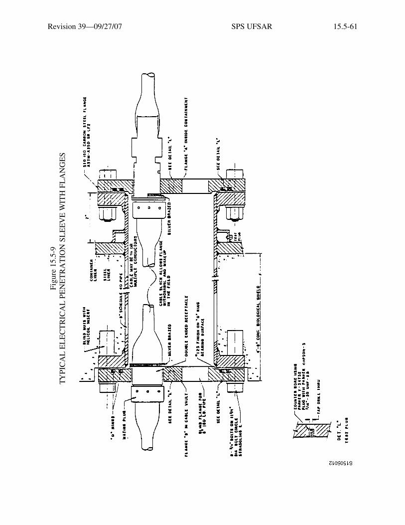
Revision 39—09/27/07 SPS UFSAR 15.5-61
Figu
re15
.5-9
TY
PIC
AL
EL
EC
TR
ICA
L P
EN
ET
RA
TIO
N S
LE
EV
E W
ITH
FL
AN
GE
S
Etia
m v
enen
atis
acc
umsa
n en
im. M
auris
rut
rum
, dia
m q
uis
tinci
dunt
ele
men
tum
, sem
orc
i bib
endu
m li
bero
, ut e
lem
entu
m
just
o m
agna
at a
ugue
. Aliq
uam
sap
ien
mas
sa, f
auci
bus
ac, e
lem
entu
m n
on, l
aore
et n
ec, f
elis
. Ves
tibul
um a
ccum
san
sagi
ttis
ipsu
m. I
n ul
lam
corp
er, d
ui s
ed c
ursu
s eu
ism
od, a
nte
wis
i dap
ibus
ligu
la, i
d rh
oncu
s ip
sum
mi a
t tel
lus.
Cla
ss a
pten
t ta
citi
soci
osqu
ad
litor
a to
rque
nt p
er c
onub
ia n
ostr
a, p
er in
cept
os h
ymen
aeos
. Qui
sque
rho
ncus
wis
i vita
e do
lor.
Etia
m
elei
fend
. Int
eger
impe
rdie
t veh
icul
a an
te. S
ed in
arc
u et
odi
o ac
cum
san
port
a. A
enea
n m
i. V
ivam
us n
on o
rci v
itae
urna
al
ique
t ulla
mco
rper
. Cla
ss a
pten
t tac
iti s
ocio
squ
ad li
tora
torq
uent
per
con
ubia
nos
tra,
per
ince
ptos
hym
enae
os. I
n fr
ingi
lla
ligul
a ve
l odi
o. In
hac
hab
itass
e pl
atea
dic
tum
st. E
tiam
tem
pus
lacu
s ac
arc
u. P
raes
ent n
on li
bero
.
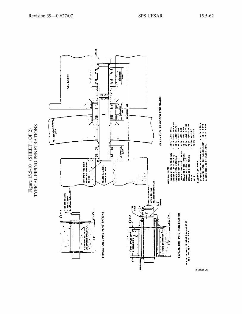
Revision 39—09/27/07 SPS UFSAR 15.5-62
Figu
re15
.5-1
0 (
SHE
ET
1 O
F 2)
TYPI
CA
L P
IPIN
G P
EN
ET
RA
TIO
NS
Etia
m v
enen
atis
acc
umsa
n en
im. M
auris
rut
rum
, dia
m q
uis
tinci
dunt
ele
men
tum
, sem
orc
i bib
endu
m li
bero
, ut e
lem
entu
m
just
o m
agna
at a
ugue
. Aliq
uam
sap
ien
mas
sa, f
auci
bus
ac, e
lem
entu
m n
on, l
aore
et n
ec, f
elis
. Ves
tibul
um a
ccum
san
sagi
ttis
ipsu
m. I
n ul
lam
corp
er, d
ui s
ed c
ursu
s eu
ism
od, a
nte
wis
i dap
ibus
ligu
la, i
d rh
oncu
s ip
sum
mi a
t tel
lus.
Cla
ss a
pten
t ta
citi
soci
osqu
ad
litor
a to
rque
nt p
er c
onub
ia n
ostr
a, p
er in
cept
os h
ymen
aeos
. Qui
sque
rho
ncus
wis
i vita
e do
lor.
Etia
m
elei
fend
. Int
eger
impe
rdie
t veh
icul
a an
te. S
ed in
arc
u et
odi
o ac
cum
san
port
a. A
enea
n m
i. V
ivam
us n
on o
rci v
itae
urna
al
ique
t ulla
mco
rper
. Cla
ss a
pten
t tac
iti s
ocio
squ
ad li
tora
torq
uent
per
con
ubia
nos
tra,
per
ince
ptos
hym
enae
os. I
n fr
ingi
lla
ligul
a ve
l odi
o. In
hac
hab
itass
e pl
atea
dic
tum
st. E
tiam
tem
pus
lacu
s ac
arc
u. P
raes
ent n
on li
bero
.

Revision 39—09/27/07 SPS UFSAR 15.5-63
Figu
re15
.5-1
0 (
SHE
ET
2 O
F 2)
TYPI
CA
L P
IPIN
G P
EN
ET
RA
TIO
NS
Etia
m v
enen
atis
acc
umsa
n en
im. M
auris
rut
rum
, dia
m q
uis
tinci
dunt
ele
men
tum
, sem
orc
i bib
endu
m li
bero
, ut e
lem
entu
m
just
o m
agna
at a
ugue
. Aliq
uam
sap
ien
mas
sa, f
auci
bus
ac, e
lem
entu
m n
on, l
aore
et n
ec, f
elis
. Ves
tibul
um a
ccum
san
sagi
ttis
ipsu
m. I
n ul
lam
corp
er, d
ui s
ed c
ursu
s eu
ism
od, a
nte
wis
i dap
ibus
ligu
la, i
d rh
oncu
s ip
sum
mi a
t tel
lus.
Cla
ss a
pten
t ta
citi
soci
osqu
ad
litor
a to
rque
nt p
er c
onub
ia n
ostr
a, p
er in
cept
os h
ymen
aeos
. Qui
sque
rho
ncus
wis
i vita
e do
lor.
Etia
m
elei
fend
. Int
eger
impe
rdie
t veh
icul
a an
te. S
ed in
arc
u et
odi
o ac
cum
san
port
a. A
enea
n m
i. V
ivam
us n
on o
rci v
itae
urna
al
ique
t ulla
mco
rper
. Cla
ss a
pten
t tac
iti s
ocio
squ
ad li
tora
torq
uent
per
con
ubia
nos
tra,
per
ince
ptos
hym
enae
os. I
n fr
ingi
lla
ligul
a ve
l odi
o. In
hac
hab
itass
e pl
atea
dic
tum
st. E
tiam
tem
pus
lacu
s ac
arc
u. P
raes
ent n
on li
bero
.
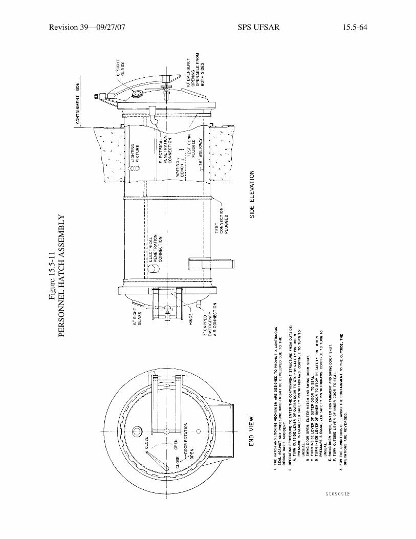
Revision 39—09/27/07 SPS UFSAR 15.5-64
Figu
re15
.5-1
1 PE
RSO
NN
EL
HA
TC
H A
SSE
MB
LY
Etia
m v
enen
atis
acc
umsa
n en
im. M
auris
rut
rum
, dia
m q
uis
tinci
dunt
ele
men
tum
, sem
orc
i bib
endu
m li
bero
, ut e
lem
entu
m
just
o m
agna
at a
ugue
. Aliq
uam
sap
ien
mas
sa, f
auci
bus
ac, e
lem
entu
m n
on, l
aore
et n
ec, f
elis
. Ves
tibul
um a
ccum
san
sagi
ttis
ipsu
m. I
n ul
lam
corp
er, d
ui s
ed c
ursu
s eu
ism
od, a
nte
wis
i dap
ibus
ligu
la, i
d rh
oncu
s ip
sum
mi a
t tel
lus.
Cla
ss a
pten
t ta
citi
soci
osqu
ad
litor
a to
rque
nt p
er c
onub
ia n
ostr
a, p
er in
cept
os h
ymen
aeos
. Qui
sque
rho
ncus
wis
i vita
e do
lor.
Etia
m
elei
fend
. Int
eger
impe
rdie
t veh
icul
a an
te. S
ed in
arc
u et
odi
o ac
cum
san
port
a. A
enea
n m
i. V
ivam
us n
on o
rci v
itae
urna
al
ique
t ulla
mco
rper
. Cla
ss a
pten
t tac
iti s
ocio
squ
ad li
tora
torq
uent
per
con
ubia
nos
tra,
per
ince
ptos
hym
enae
os. I
n fr
ingi
lla
ligul
a ve
l odi
o. In
hac
hab
itass
e pl
atea
dic
tum
st. E
tiam
tem
pus
lacu
s ac
arc
u. P
raes
ent n
on li
bero
.

Revision 39—09/27/07 SPS UFSAR 15.5-65
Figu
re15
.5-1
2 TY
PIC
AL
LIN
ER
DE
TA
ILS
Etia
m v
enen
atis
acc
umsa
n en
im. M
auris
rut
rum
, dia
m q
uis
tinci
dunt
ele
men
tum
, sem
orc
i bib
endu
m li
bero
, ut e
lem
entu
m
just
o m
agna
at a
ugue
. Aliq
uam
sap
ien
mas
sa, f
auci
bus
ac, e
lem
entu
m n
on, l
aore
et n
ec, f
elis
. Ves
tibul
um a
ccum
san
sagi
ttis
ipsu
m. I
n ul
lam
corp
er, d
ui s
ed c
ursu
s eu
ism
od, a
nte
wis
i dap
ibus
ligu
la, i
d rh
oncu
s ip
sum
mi a
t tel
lus.
Cla
ss a
pten
t ta
citi
soci
osqu
ad
litor
a to
rque
nt p
er c
onub
ia n
ostr
a, p
er in
cept
os h
ymen
aeos
. Qui
sque
rho
ncus
wis
i vita
e do
lor.
Etia
m
elei
fend
. Int
eger
impe
rdie
t veh
icul
a an
te. S
ed in
arc
u et
odi
o ac
cum
san
port
a. A
enea
n m
i. V
ivam
us n
on o
rci v
itae
urna
al
ique
t ulla
mco
rper
. Cla
ss a
pten
t tac
iti s
ocio
squ
ad li
tora
torq
uent
per
con
ubia
nos
tra,
per
ince
ptos
hym
enae
os. I
n fr
ingi
lla
ligul
a ve
l odi
o. In
hac
hab
itass
e pl
atea
dic
tum
st. E
tiam
tem
pus
lacu
s ac
arc
u. P
raes
ent n
on li
bero
.
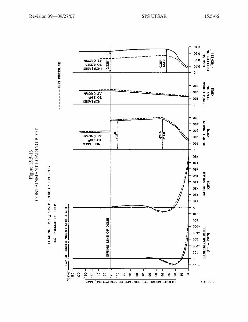
Revision 39—09/27/07 SPS UFSAR 15.5-66
Figu
re15
.5-1
3 C
ON
TA
INM
EN
T L
OA
DIN
G P
LO
T
Etia
m v
enen
atis
acc
umsa
n en
im. M
auris
rut
rum
, dia
m q
uis
tinci
dunt
ele
men
tum
, sem
orc
i bib
endu
m li
bero
, ut e
lem
entu
m
just
o m
agna
at a
ugue
. Aliq
uam
sap
ien
mas
sa, f
auci
bus
ac, e
lem
entu
m n
on, l
aore
et n
ec, f
elis
. Ves
tibul
um a
ccum
san
sagi
ttis
ipsu
m. I
n ul
lam
corp
er, d
ui s
ed c
ursu
s eu
ism
od, a
nte
wis
i dap
ibus
ligu
la, i
d rh
oncu
s ip
sum
mi a
t tel
lus.
Cla
ss a
pten
t ta
citi
soci
osqu
ad
litor
a to
rque
nt p
er c
onub
ia n
ostr
a, p
er in
cept
os h
ymen
aeos
. Qui
sque
rho
ncus
wis
i vita
e do
lor.
Etia
m
elei
fend
. Int
eger
impe
rdie
t veh
icul
a an
te. S
ed in
arc
u et
odi
o ac
cum
san
port
a. A
enea
n m
i. V
ivam
us n
on o
rci v
itae
urna
al
ique
t ulla
mco
rper
. Cla
ss a
pten
t tac
iti s
ocio
squ
ad li
tora
torq
uent
per
con
ubia
nos
tra,
per
ince
ptos
hym
enae
os. I
n fr
ingi
lla
ligul
a ve
l odi
o. In
hac
hab
itass
e pl
atea
dic
tum
st. E
tiam
tem
pus
lacu
s ac
arc
u. P
raes
ent n
on li
bero
.
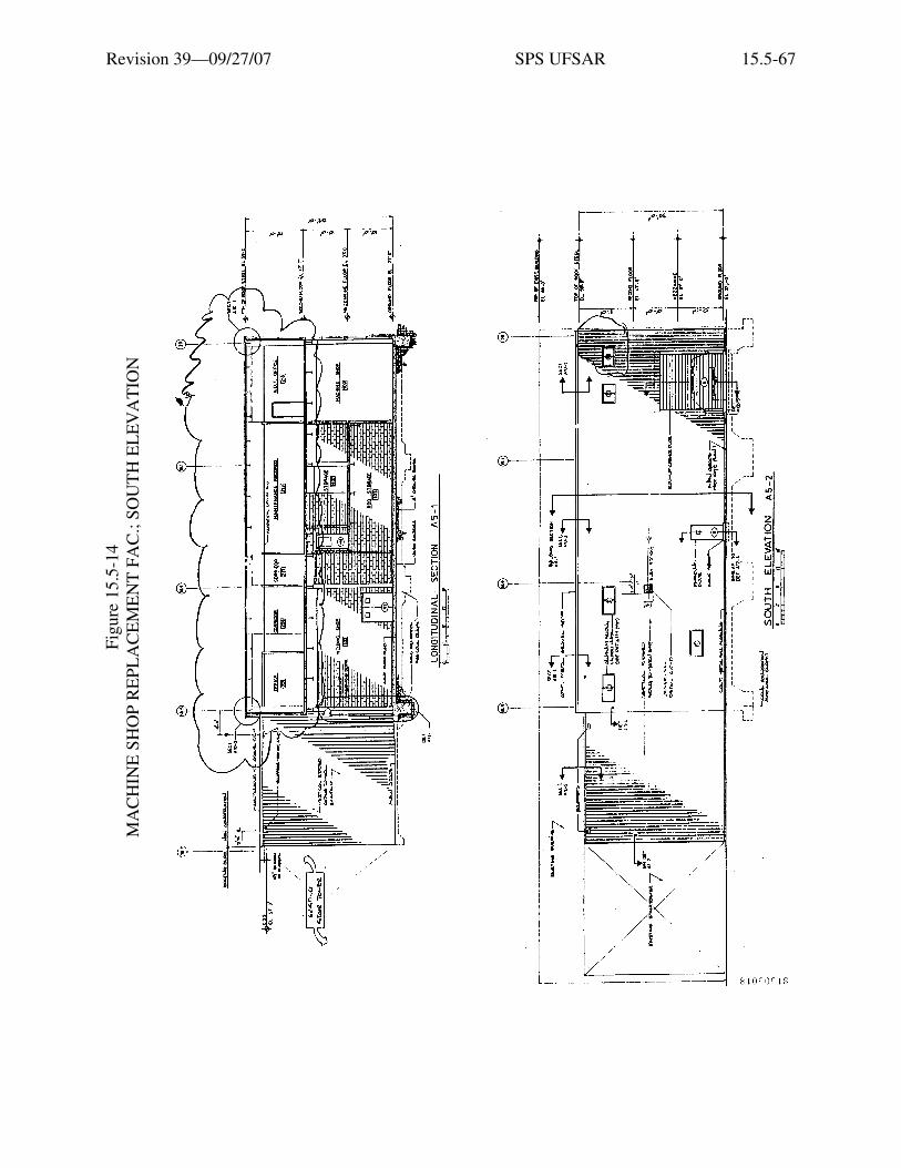
Revision 39—09/27/07 SPS UFSAR 15.5-67
Figu
re15
.5-1
4 M
AC
HIN
E S
HO
P R
EPL
AC
EM
EN
T F
AC
.; SO
UT
H E
LE
VA
TIO
N
Etia
m v
enen
atis
acc
umsa
n en
im. M
auris
rut
rum
, dia
m q
uis
tinci
dunt
ele
men
tum
, sem
orc
i bib
endu
m li
bero
, ut e
lem
entu
m
just
o m
agna
at a
ugue
. Aliq
uam
sap
ien
mas
sa, f
auci
bus
ac, e
lem
entu
m n
on, l
aore
et n
ec, f
elis
. Ves
tibul
um a
ccum
san
sagi
ttis
ipsu
m. I
n ul
lam
corp
er, d
ui s
ed c
ursu
s eu
ism
od, a
nte
wis
i dap
ibus
ligu
la, i
d rh
oncu
s ip
sum
mi a
t tel
lus.
Cla
ss a
pten
t ta
citi
soci
osqu
ad
litor
a to
rque
nt p
er c
onub
ia n
ostr
a, p
er in
cept
os h
ymen
aeos
. Qui
sque
rho
ncus
wis
i vita
e do
lor.
Etia
m
elei
fend
. Int
eger
impe
rdie
t veh
icul
a an
te. S
ed in
arc
u et
odi
o ac
cum
san
port
a. A
enea
n m
i. V
ivam
us n
on o
rci v
itae
urna
al
ique
t ulla
mco
rper
. Cla
ss a
pten
t tac
iti s
ocio
squ
ad li
tora
torq
uent
per
con
ubia
nos
tra,
per
ince
ptos
hym
enae
os. I
n fr
ingi
lla
ligul
a ve
l odi
o. In
hac
hab
itass
e pl
atea
dic
tum
st. E
tiam
tem
pus
lacu
s ac
arc
u. P
raes
ent n
on li
bero
.
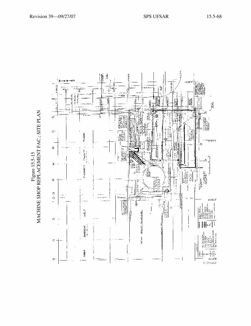
Revision 39—09/27/07 SPS UFSAR 15.5-68
Figu
re15
.5-1
5 M
AC
HIN
E S
HO
P R
EPL
AC
EM
EN
T F
AC
.; SI
TE
PL
AN
Etia
m v
enen
atis
acc
umsa
n en
im. M
auris
rut
rum
, dia
m q
uis
tinci
dunt
ele
men
tum
, sem
orc
i bib
endu
m li
bero
, ut e
lem
entu
m
just
o m
agna
at a
ugue
. Aliq
uam
sap
ien
mas
sa, f
auci
bus
ac, e
lem
entu
m n
on, l
aore
et n
ec, f
elis
. Ves
tibul
um a
ccum
san
sagi
ttis
ipsu
m. I
n ul
lam
corp
er, d
ui s
ed c
ursu
s eu
ism
od, a
nte
wis
i dap
ibus
ligu
la, i
d rh
oncu
s ip
sum
mi a
t tel
lus.
Cla
ss a
pten
t ta
citi
soci
osqu
ad
litor
a to
rque
nt p
er c
onub
ia n
ostr
a, p
er in
cept
os h
ymen
aeos
. Qui
sque
rho
ncus
wis
i vita
e do
lor.
Etia
m
elei
fend
. Int
eger
impe
rdie
t veh
icul
a an
te. S
ed in
arc
u et
odi
o ac
cum
san
port
a. A
enea
n m
i. V
ivam
us n
on o
rci v
itae
urna
al
ique
t ulla
mco
rper
. Cla
ss a
pten
t tac
iti s
ocio
squ
ad li
tora
torq
uent
per
con
ubia
nos
tra,
per
ince
ptos
hym
enae
os. I
n fr
ingi
lla
ligul
a ve
l odi
o. In
hac
hab
itass
e pl
atea
dic
tum
st. E
tiam
tem
pus
lacu
s ac
arc
u. P
raes
ent n
on li
bero
.

Revision 39—09/27/07 SPS UFSAR 15.5-69
Figu
re15
.5-1
6 M
AC
HIN
E S
HO
P R
EPL
AC
EM
EN
T F
AC
.; E
AST
/WE
ST E
LE
VS.
Etia
m v
enen
atis
acc
umsa
n en
im. M
auris
rut
rum
, dia
m q
uis
tinci
dunt
ele
men
tum
, sem
orc
i bib
endu
m li
bero
, ut e
lem
entu
m
just
o m
agna
at a
ugue
. Aliq
uam
sap
ien
mas
sa, f
auci
bus
ac, e
lem
entu
m n
on, l
aore
et n
ec, f
elis
. Ves
tibul
um a
ccum
san
sagi
ttis
ipsu
m. I
n ul
lam
corp
er, d
ui s
ed c
ursu
s eu
ism
od, a
nte
wis
i dap
ibus
ligu
la, i
d rh
oncu
s ip
sum
mi a
t tel
lus.
Cla
ss a
pten
t ta
citi
soci
osqu
ad
litor
a to
rque
nt p
er c
onub
ia n
ostr
a, p
er in
cept
os h
ymen
aeos
. Qui
sque
rho
ncus
wis
i vita
e do
lor.
Etia
m
elei
fend
. Int
eger
impe
rdie
t veh
icul
a an
te. S
ed in
arc
u et
odi
o ac
cum
san
port
a. A
enea
n m
i. V
ivam
us n
on o
rci v
itae
urna
al
ique
t ulla
mco
rper
. Cla
ss a
pten
t tac
iti s
ocio
squ
ad li
tora
torq
uent
per
con
ubia
nos
tra,
per
ince
ptos
hym
enae
os. I
n fr
ingi
lla
ligul
a ve
l odi
o. In
hac
hab
itass
e pl
atea
dic
tum
st. E
tiam
tem
pus
lacu
s ac
arc
u. P
raes
ent n
on li
bero
.

Revision 39—09/27/07 SPS UFSAR 15.5-70
Intentionally Blank

Revision 39—09/27/07 SPS UFSAR 15.6-1
15.6 OTHER CLASS I STRUCTURES
Class I structures other than the reactor containment structure are listed in Table 15.2-1. Themajor structures include the auxiliary building, control room area, including switchgear and relayrooms; fuel building; emergency diesel-generator rooms; containment auxiliary structures thatcontain main steam and feedwater isolation valves, recirculation spray and low-head safetyinjection pump cubicles, auxiliary steam generator feed pump cubicle, and safeguards ventilationroom; and circulating water intake structures, including the high-level canal.
The fuel building, the main steam and feedwater isolation valve section of the containmentauxiliary structures, and the refueling water storage tanks are supported on reinforced-concretemats on concrete-filled steel pipe piles. All other structures are soil-supported onreinforced-concrete mats or spread footings. All Class I structures designed to meet tornadomissile criteria, as listed in Table 15.2-1, are enclosed with heavily reinforced, 2-foot-thickconcrete walls and roof slabs with all openings shielded against missiles.
Class I structures are designed to resist the operating-basis earthquake without exceedingallowable working stresses, where allowable stresses are one-third above the normal applicablecode normal working stress. For concrete structures, a 5% critical damping function is assumed,and the accelerations selected from the acceleration response spectrum curves are considered inconjunction with the natural frequency of each structure. A check has been made to ensure thatcollapse-type failures will not occur under the design-basis earthquake. For this condition, a 10%damping factor is assumed for concrete structures, and stresses are limited to not more than 120%of the minimum yield point stress. In practice, the controlling feature of the design of thesestructures was to the satisfaction of the operating-basis earthquake requirements with the limited5% damping factor.
The high-level intake canal is formed by excavating to Elevation +5 ft. from an averagegrade of approximately 35 feet. Earth fill dikes constructed on either side of the canal bring thefinished height to Elevation +36 ft. throughout the length of the canal. The interior surfaces of thecanal are lined with a 4.5-inch-thick reinforced-concrete slab. Under drains and pressure reliefvalves are provided to prevent uplift of the concrete liner by unbalanced hydrostatic pressure.
15.6.1 Other Structures
All other structures are designed to adequately support all dead, live, and wind loads. Wherenecessary, subsurface walls and slabs are designed to resist the horizontal component of the soilwith applicable surcharge and hydrostatic pressures.
Structural steel design conforms to the 1963 issue of the Specification for the Design,Fabrication and Erection of Structural Steel for Buildings of the American Institute of SteelConstruction. All concrete work is designed in accordance with the Building Code Requirementsfor Reinforced Concrete, serial designation 318-63 of the American Concrete Institute. Accessand egress requirements, as well as fire ratings of walls and floor systems, satisfy the

Revision 39—09/27/07 SPS UFSAR 15.6-2
requirements of the Basic Building Code of the Building Officials Conference of America, 1966issue.
Under the design-basis accident loading, the allowable stresses do not exceed 90% of theminimum yield strength of the structural steel. From mill test reports, the yield strength ofstructural steel is 42,000 psi, with an ultimate strength of 63,000 psi. Using a minimum yield of36,000 psi for A36 steel, the design-allowable stress is 90% of 36,000 = 32,400 psi.
Design-allowable stress for structural steel is = 51.5% of the ultimate strength.
Tests on special reinforcing steel with a minimum yield of 50,000 psi have resulted in yieldstrength of 55,500 psi, with an ultimate strength of 90,000 psi; with a design-allowable stress of90% of minimum yield, the design-allowable stress is 0.9 × 50,000 = 45,000 psi.
Design-allowable stress on reinforcing is = 50% of ultimate strength.
Concrete continues to increase in strength beyond the 28-day strength of 3000 psi. TheBureau of Reclamation Concrete Manual indicates that Type II cement concrete can be expectedto increase in strength approximately 30% in 1 year from the 28-day strength.
Approximate 28-day strength for 3000-psi concrete from test reports = 3800 psi
Design allowable 85% of 3000 psi = 2500 psi
Ultimate strength in 1 year = 1.3 × 3800 = 4950 psi
Design allowable is = 51% of ultimate strength in 1 year.
The above figures show that, for structures designed for the design-basis accident loading,structural steel and reinforced concrete are designed at approximately 50% of their ultimatestrength. In the design of concrete structural members under design-basis accident conditions,concrete strength is not the controlling factor.
Allowable soil bearing values for foundations are determined from the soil boring logs andthe results of triaxial shear tests of the soil. Applicable factors of safety are applied to the testresults.
15.6.2 Reactor Coolant System Supports
The reactor coolant system includes the reactor vessel, three steam generators, three reactorcoolant pumps, and a pressurizer for each unit. Structures are provided to support these heavyvessels and equipment, and to ensure system integrity during normal operation and design-basisaccident conditions.
The primary equipment supports of the reactor coolant system are designed to withstand thedesign-basis earthquake acting simultaneously with an instantaneously applied pipe break. The
32 400,63 000,------------------
45 000,90 000,------------------
25004950------------

Revision 39—09/27/07 SPS UFSAR 15.6-3
original configuration of the RCS equipment supports included ten large-bore (12-inch diameter)hydraulic snubbers per loop to carry the loads from postulated reactor coolant system, main steamline and feedwater pipe ruptures.
Subsequently, studies to address Unresolved Safety Issue A-2 (effects of asymmetricpressure loads resulting from PWR primary loop ruptures) concluded that the probability ofrupture of the primary coolant loop is extremely small, and that the presence of a pipe crack couldbe detected by leakage well before the crack grew to critical size which would cause rupture.These “leak-before-break” analyses, documented in References 1 and 2, were submitted to theNRC on behalf of the Westinghouse Owners Group, which included Surry Power Station.
NRC Generic Letter 84-04, Safety Evaluation of Westinghouse Topical Reports Dealingwith Elimination of Postulated Pipe Breaks in PWR Primary Loops, provided the NRC staff safetyevaluation concluding that, provided certain specific conditions are met, an acceptable technicalbasis exists so that asymmetric pressure loads resulting from pipe breaks in the reactor coolantsystem primary loop need not be considered as a design basis for the reviewed plants. Theplant-specific conditions were a limitation on the maximum bending moments in the primary looppiping for normal operating and seismic loadings, and the existence of an adequate reactor coolantleakage detection system. The affected plants were encouraged to submit requests for partialexemptions from General Design Criterion 4 (GDC-4), to permit elimination of pipe rupturerestraints required to protect against these previously postulated breaks.
Because a number of the large-bore snubbers served primarily as pipe rupture restraints,Surry proceeded with an exemption request to allow elimination of 6 of the 10 snubbers per loop,based on application of leak-before-break in accordance with Generic Letter 84-04. (The other4 large-bore snubbers on the upper steam generator support were required for lateral loads due toa postulated longitudinal split of the main steam line.) The reactor coolant loop system wasre-evaluated with all snubbers on the steam generator lower support and the reactor coolant pumpsupports eliminated, to assure that the conditions of pressure, deadweight, thermal, seismic, andremaining pipe rupture effects, would not result in unacceptable stress levels or factors of safety.Largely independent analyses were performed by Westinghouse and Stone & Webster inaccordance with the original division of design responsibilities. Interface force allowable limits atNSSS boundaries were assured and support design load interfaces were reviewed for acceptance.
The exemption request to allow elimination of 18 snubbers per unit was filed with the NRCon November 5, 1985 (Reference 3). The detailed technical basis (Reference 4) provided separateattachments addressing load evaluation, leakage detection, and net safety balance. The proposeddesign changes were discussed with the NRC and resulting NRC concerns were addressed(References 5 & 6). The GDC-4 “limited scope” revision (Reference 7) was subsequentlypublished (effective May 12, 1986) permitting the use of leak-before-break technology to justifyelimination of the dynamic effects of primary loop breaks from the design basis of PWRs. Withthe publication of the notice of revision to GDC-4, a license amendment to the plant design basiswas requested to implement the snubber reductions under the new rule (Reference 8). By letter

Revision 39—09/27/07 SPS UFSAR 15.6-4
dated June 16, 1986, the NRC approved the license amendment (#108) for both units(Reference 9). The snubber eliminations were implemented by Design Changes 85-04-1and 86-12-2.
Subsequently, the NRC issued Generic Letter 87-11, Relaxation of Arbitrary IntermediateBreaks which provided the revised Mechanical Engineering Branch position eliminating the needto postulate Arbitrary Intermediate Breaks. As stated in the generic letter, the elimination ofArbitrary Intermediate Breaks allows elimination of the associated pipe whip restraints and jetimpingement shields. Because the stresses in the main steam lines inside containment are wellbelow the stress criteria for required mandatory intermediate breaks, the only breaks which needto be postulated are terminal end breaks which do not apply lateral loads to the steam generator.Therefore, the governing lateral loads on the steam generator become those imposed by the mainfeedwater break, which are low enough that only a single snubber in each pair will be required tocarry the load. Analyses were performed by Westinghouse and Stone & Webster similar to thoseperformed for the earlier large-bore snubber reduction to ensure piping stress levels andcomponent factors of safety were acceptable. In addition, it was necessary to verify that the basisfor the previous license amendment based upon leak-before-break of the primary loop remainedvalid. Comparison of results with the lower large-bore snubber of each pair removed as a result ofeliminating the main steam line split vs. the results in the previous leak-before-break submittals,confirmed that there were no significant reduction in margins of safety. Therefore, elimination ofthe lower large-bore snubber of each pair does not compromise the bases for the previousleak-before-break analysis, namely:
1. The loading on the primary loop piping is still enveloped by the generic analyses submittedon behalf of the A-2 Owners Group, and accepted by the NRC staff in Generic Letter 84-04,and specifically for Surry by NRC letter dated June 16, 1986; and
2. The reactor coolant system equipment, piping, and supports continue to have acceptablemargins of safety under licensed loading conditions other than the now-eliminated rupturesof the primary loop piping and Arbitrary Intermediate Break of the main steam lines.
15.6.2.1 Design Basis
All supports in the reactor coolant system are designed to withstand the design-basisearthquake acting simultaneously with an instantaneously applied pipe break. As discussed above,it is no longer necessary to consider the dynamic effects of a postulated rupture of the primaryreactor coolant loop. However, single ruptures are postulated to occur in either the pressurizersurge or other reactor coolant branch lines, the main steam piping, or the main feedwater piping.In general, two types of piping failures are considered: a double-ended rupture, or a longitudinalrupture on either the horizontal or vertical axis of the pipe. The longitudinal rupture area wastaken to be equal to the area of the double-ended rupture for these piping failures. Stresses in themain steam piping inside containment have been reviewed and, in accordance with NRC GenericLetter 87-11, are sufficiently low that no intermediate break need be postulated. Only terminalend breaks need be postulated; in accordance with Generic Letter 87-11, it is not necessary to
Revision 39—09/27/07 SPS UFSAR 15.6-5
postulate longitudinal rupture at terminal end breaks. Therefore, only vertical loads are consideredto be applied to the steam generators due to a postulated main steam line break. For all postulatedbreaks, the pipe rupture loads are combined with design-basis seismic loads by thesquare-root-sum-of-squares (SRSS) method.
The peak value of the pipe thrust for any of the main steam piping breaks considered isapproximately 620,000 lb; and the peak value for the pipe thrust for the pressurizer surge pipebreak is approximately 195,000 lb. These thrust values are equal to P × A, the system pressuretimes rupture area.
For the pressurizer surge line break, the load versus time transients of these breaks areprovided by a computer program that analyzes the shock wave initiated at the break as it passesthrough the complete piping loop. Results from this program are used as forcing functions in astructural dynamic program that results in the dynamic loadings of the supports. For the mainsteam line and feedwater line breaks, the dynamic forces were applied only at the steam generatornozzles, because the primary reactor coolant loop piping remains intact. The peak values of thepipe thrust for the postulated piping breaks were computed as Cr × P × A, the thrust coefficienttimes the system pressure times the rupture area. These values were used as the basis fordeveloping conservative time-history forcing functions of the postulated breaks. In addition to thethrust loading, jet impingement effects were included as appropriate. For the main steam linevertical break, credit was taken in calculating the thrust loading for the flow area reduction of theflow restrictors installed at the nozzle during the steam generator replacement project; the jetimpingement loading is not reduced by the flow reducers. The time-history forcing functions areinput into the structural dynamic analysis program that calculates maximum loadings on thesupports. For each analyzed break, the maximum support loads are determined and then combinedby SRSS summation with design-basis earthquake loads, and then added directly to the loadingsdue to normal operation. Combined stresses are maintained within 90% of the minimum yieldpoint of the structural material used.
All welding is in accordance with Section IX of the ASME Code, and all welds areexamined by either radiographic, sonic, dye penetrant, or magnetic particle techniques, dependingon the material and the state of stress at the weld.
The seismic restraints (snubbers) that are installed on the piping systems throughout theplant and that are required to protect the reactor coolant system or any other safety-related systemare subject to operability and surveillance requirements contained within the TechnicalSpecifications. Vepco has established a program and procedures for inspecting, testing, andmaintaining snubbers in compliance with the Technical Specification requirements. A listing ofall safety-related hydraulic and mechanical snubbers is maintained by Surry Power Station.
Revision 39—09/27/07 SPS UFSAR 15.6-6
15.6.2.2 Description
15.6.2.2.1 Reactor Vessel Support
The reactor vessel is supported by six sliding foot assemblies mounted on the neutron shieldtank. The support feet are designed to restrain lateral and rotational movement of the reactorvessel while allowing thermal expansion. The neutron shield tank is a double-walled cylindricalstructure that transfers the loadings to the heavy reinforced-concrete mat of the containmentstructure. The tank also serves to minimize gamma and neutron heating of the primary concreteshield, and to attenuate neutron radiation outside of the primary shield to acceptable limits(Section 11.3.2.1). The neutron shield tank assembly and material listing are shown onFigure 15.6-1.
Sliding support blocks mounted on top of the shield tank support the reactor vessel. Thesesliding support blocks permit radial thermal expansion of the reactor vessel, while preventingtranslation, rotation, or uplifting. The support blocks are also designed to adjust to the correctheight for plumbing the reactor vessel and for distributing the load properly among the sixsupports.
The loading conditions used in the analysis of the neutron shield tank were the simultaneousaccelerations of a design-basis earthquake, the thrust forces exerted by the reactor vessel due to adouble-ended reactor coolant pipe rupture,1 and the dead weight of the system and the tank itself,with stresses not to exceed allowable working stresses, and with no loss of integrity or function.
The neutron shield tank has been designed using the theory of a shell structure, dynamicallyloaded in both horizontal and axial planes, which results in meridional and circumferentialstresses at all points along its length. The stresses in the tank were determined by using themethods and theories of Timoshenko for plates and shells, elasticity, and elastic stability. Allmembrane stress levels were held to the limits stated in Section VIII of the ASME Code; allmembrane-plus-bending stresses were held to 90% of yield point. Section VIII of the ASMEBoiler and Pressure Vessel Code was used as a guide in the fabrication and welding of the tank. Acode stamp was not required, since this is not a code pressure vessel but a supporting structure forthe reactor pressure vessel.
All material employed in the fabrication of the tank was new and conformed to ASTMStandards. The tank shell was constructed from ASTM A516, Grade 60, and the six slidingsupport blocks were made of maraged steel. The material has an NDT of -20° to -40°F. Dropweight tests were performed to determine the nil ductility transition temperature of the depositedweld metal in welding the ASTM A516, Grade 60 material with an NDT of -40°F. The maragedsteel was ultrasonically tested for flaws to the quality level of MIL-1-8950. Flaws detectedultrasonically were verified by X-ray. Maraged steel pieces with verified flaws larger than 1/32 in.
1. As discussed previously in this section, it is no longer necessary to consider the dynamic effects of a postulated rupture of the primary reactor coolant loop piping. However, pipe ruptures of reactor coolant branch lines must still be considered.
Revision 39—09/27/07 SPS UFSAR 15.6-7
were rejected. The maraged steel had a maximum hardness of 35 Rockwell C and a minimumgrain size of 6, in accordance with ASTM E-112 and MIL-Std-430, Macrograph Standards forSteel Bars, Billets, and Blooms. The nonmetallic inclusion content for each billet was determinedin accordance with ASTM E45. Fracture toughness tests were performed on maraged steel inaccordance with ASTM Specification, Proposed Recommended Practice for Plane-StrainFracture Toughness Testing of High-Strength Metallic Materials Using a Fatigue-Cracked BendSpecimen, Part 31, ASTM Standards.
All welds, where possible, were 100% radiographed in accordance with Paragraph UW-51of the ASME Boiler and Pressure Vessel Code Section VIII, Division 1. Other welds that couldnot be radiographed were dye-penetrant checked at root pass, intermediate depths at half-inchincrements, and the final pass, or magnetic-particle tested, in accordance with Appendices VIand VIII, Section VIII, ASME Boiler and Pressure Vessel Code. The surfaces of welds wereground to a surface condition suitable for the inspection procedure employed. Defects in weldswere removed by chipping, grinding, or arc gouging until sound metal was reached. The resultingcavity was rewelded, employing an approved procedure.
After shop fabrication, the completed tank was subjected to a hydrostatic test of 15 psi,measured at the top of the tank. No water loss was observed for a 24-hour period. The tank wasthen leak tested with air at 5 psi gauge, applying soapsuds to all welds accessible from outside thetank. Leaks were repaired and the tank retested until no leakage was detected. All tests wererecorded and certified. After installation of the neutron shield tank at the job site, the tank washydrostatically retested.
15.6.2.2.2 Steam Generator Support
The steam generator support consists of two (upper and lower) cast rings and associatedsuspension rods, lateral restraints and snubbers. The lower ring, which carries the steam generatorweight, is suspended by means of three pipe columns. Hydraulic snubber cylinders and rigidlateral guides connect the upper casting to the steam generator cubicle structure to allow guidedthermal expansion of the steam generator outward from the reactor during normal operation,while resisting movement during seismic and pipe break conditions. Due to the design of thissupport system (i.e., pin-ended connections at all member joints) lamellar tearing of the supportscould not occur. The steam generator support assembly and material listing is shown onFigure 15.6-2. The supports do not have any heavy section intersecting member weldments.
The major materials used in the construction of the steam generator supports are listed inTable 15.6-1. The difference between the operating temperature and the NDT of the materialensures toughness and ductility of the steam generator supports under all operating conditions.Welding associated with the supports was conducted in accordance with Section IX of the ASMEcode.
In addition to numerous inspections and tests carried out by the material suppliers andfabricators, all of the components for these supports were subject to inspection during fabrication

Revision 39—09/27/07 SPS UFSAR 15.6-8
and installation by Stone & Webster Engineering Corporation. All welds were subjected toexamination by either the magnetic particle, liquid penetrant, or radiographic methods. TheVascomax 350 CVM and 300 CVM materials, and the A-352 grade LC3 casting materials weresubjected to examination by the magnetic particle and ultrasonic methods. A visual inspection ofa portion of these supports is required by the Technical Specifications.
The upper restraining ring is composed of two girth straps coupled together by studs to forma continuous ring. The studs are 1.25-inch 12UNF-2A Vascomax 18% Ni, maraging grade 350,with nickel cadmium coating. The nuts are 1.25-inch 12UNF-3B Vascomax 18% Ni, maraginggrade 250, with Helicoil inserts. The studs and nuts are designed to minimize stress concentrationduring manufacture, and the studs are coated for environmental protection. The studs arepretensioned across a joint flange spacer block, which serves to reduce bending stresses in thestuds.
A total of nine machined shoe openings are welded to each vessel girth strap. These shoeopenings accommodate nine keys which themselves are fastened by dowels to the large upperrestraint casting which is shown on Figure 15.6-2. These key and shoe openings function to allowvertical thermal expansion of the steam generator within the upper restraint casting, but willrestrict lateral movement resulting from forces generated during a seismic event and/or a majorpipe break applying lateral loads to the steam generator.
In a seismic event and/or a major pipe break applying lateral loads to the steam generator,the shoe openings in the vessel girth straps act against the keys, which results in a tangential loadon the girth straps. The subject studs are designed to accommodate the maximum tangential loadresulting from this accident condition. Existing space restrictions and restraint design required alimitation on stud size and quantity which necessitates the use of an ultra-high strength boltingmaterial. The studs have a minimum yield strength of 326,000 psi. The nuts have a minimumyield strength of 150,000 psi.
The upper restraint casting is anchored to the containment structure (approximate 47-footlevel) through rigid lateral guides oriented in the direction perpendicular to the outward thermalmovement of the steam generator, and by two horizontal large-bore hydraulic snubbers, whichpermit the thermal movement of the steam generators outward from the reactor. The large-boresnubbers are 12-inch-diameter Pathon snubbers which have been refurbished and upgraded forincreased reliability by Paul-Monroe/Remco Hydraulics under Design Change 85-05. Themodifications included chroming the cylinder inner diameters; replacement of all non metallicseals with extended-service-life Tefzel seals or metallic seals; installation of poppet-typeself-cleaning control valves for improved performance; conversion to the standard snubberhydraulic fluid (General Electric SF-1154); and incorporation of test-in-place features. Inaddition, the original common reservoir serving a number of snubbers has been replaced byindividual pressurized reservoirs installed in more readily accessible locations in lower radiationareas outside the biological shield walls. The reservoirs are plated and the tubing and fittings arestainless steel for corrosion resistance.
Revision 39—09/27/07 SPS UFSAR 15.6-9
The lower restraining ring is also connected to the steam generator cubicle concretestructure by couplings consisting of two end plates installed perpendicular to one another. The endplates have machined dovetails and are joined by a connector plate with mating dovetails.Although the couplings are resistant to corrosion cracking, additional protection is provided byenclosing each coupling in a rubber boot filled with silicone lubricant. The boot and lubricant arecompatible with the coupling and are also radiation resistant.
15.6.2.2.3 Reactor Coolant Pump Support
The reactor coolant pumps are supported by a four-legged suspended structure. (Foursmall-bore snubbers originally installed in the upper frame structure of the pump support wereeliminated under Design Changes 85-04-1 and 86-12-2. The dynamic characteristics of thereactor coolant pump were not significantly affected by removal of these snubbers as discussed inReference 6.) The reactor coolant pump support assembly and material listing are shown onFigure 15.6-3. The supports do not have any heavy section intersecting member weldments.
The major materials used in the construction of the reactor coolant pump supports are listedin Table 15.6-2. Welding associated with the supports was conducted in accordance withSection IX of the ASME Code.
In addition to numerous inspections and tests carried out by the material suppliers andfabricators, all of the components for these supports were subject to inspection during fabricationand installation by Stone & Webster Engineering Corporation. All welds were subjected toexamination by either the magnetic particle, liquid penetrant, or radiographic methods. TheVascomax 350 CVM and 300 CVM materials, and the A-352 grade LC3 casting materials weresubjected to examination by the magnetic particle and ultrasonic methods. A visual inspection ofa portion of these supports is required by the Technical Specifications; however, there is no formalinspection program for all components of the supports during the life of the facility. Majorinspections potentially involving disassembly can be conducted on an as-needed basis.
During normal operation the loads and stresses for piping, component connections, andother remaining component supports are not sufficient to cause the failure of the reactor coolantsystem piping, should there be a complete failure of the reactor coolant pump supports. Themaximum stresses that can be expected in the reactor coolant piping as a result of failure of thereactor coolant pump supports during normal operation are summarized in Table 15.6-3. Theseloads are within the allowable nozzle loads for both the steam generator nozzle and the reactorpressure vessel nozzles. The allowable stresses for the reactor coolant pipe material (A376Tp 316) are also summarized below. While several of these values are above yield at 650°F, theyare all less than 50% of the material’s ultimate strength at that temperature. The reactor coolantpipe material has an Sn (code-allowable for normal operation) of 16 ksi at 650°F, and the faultedallowable stress would be 1.85 Sn or 28.8 ksi. All of the loads summarized below are within thisfaulted allowable, with the exception of the pressurizer inlet. However, thermal stresses have beenconservatively included, and their deletion brings the stress levels well within the allowables.

Revision 39—09/27/07 SPS UFSAR 15.6-10
During any postulated accident condition, i.e. seismic and/or pipe breaks, a concurrentcomplete failure of the reactor coolant pump support would result in unacceptable consequencesthroughout the reactor coolant loop piping, in terms of loads and stresses. If these supports wereto fail during operation, it would be detected, as there is vibration monitoring instrumentation onboth the shaft and the frame of the reactor coolant pumps. The amount of vibration is indicated inthe control room, and any excessive vibration would cause an annunciator alarm to sound in thecontrol room. To trigger the annunciator alarms, vibration greater than 3 mils on the frame andgreater than 15 mils on the pump shaft must occur.
15.6.2.2.4 Pressurizer Support
The pressurizer vessel is mounted in a rigid support ring girder suspended by three hangercolumns from above. Antisway brackets are welded to the shell of the pressurizer to accommodateshear blocks on the ring; the ring girder is laterally supported by a reinforcement plate attached toembedments in the concrete structure. In addition, lateral support for dynamic loads is providednear the vessel’s center of gravity by four gapped restraints1 at lugs on the pressurizer whichtransmit the loads into baseplates on the concrete floor. The lateral gapped restraints and hangershear blocks and reinforcement plate are able to take all incident loads while allowing thepressurizer vessel to expand radially and vertically. The pressurizer support assembly and materiallisting are shown on Figure 15.6-4.
15.6.2.2.5 Evaluation
The dynamic analysis program accounts for dynamic amplification of the support forces.These forces are then combined with the design-basis seismic loadings by SRSS summation toensure that the supports are conservatively designed to withstand the condition of a pipe breakoccurring as a result of an earthquake. Rigid quality assurance criteria during fabrication ensureconformance with the conservative design.
15.6.3 Containment Internal Structure
The reactor containment internal structure is a reinforced concrete structure that furnishes:
1. Supports and restraints for all internal equipment and piping including the polar crane and jibcrane.
2. Missile shielding for the containment steel liner and main steam lines against internallygenerated missiles.
3. Biological shielding for station operators inside the containment structure under all phases ofreactor operation.
The structure is designed to withstand the design-basis earthquake together with thesimultaneous loss-of-coolant accident (LOCA)2, without loss of function. Clearance is
1. The four lateral gapped restraints were installed by Design Changes 85-04-1 and 85-05-2 to replace the four snubbers in the original support configuration.

Revision 39—09/27/07 SPS UFSAR 15.6-11
maintained between all internal structures and the steel liner of the reactor containment shell topermit differential earthquake motion. The steam generator cubicles and the pressurizer cubicleare designed to withstand an internal differential pressure load of 35 psi resulting from thepostulated double-ended primary coolant pipe break. The primary shield is designed to withstandan internal pressure of 100 psig resulting from a hypothetical reactor coolant pipe break within theprimary shield.
The differential pressure rise within the cubicles is controlled by open and shielded ventspaces in each cubicle, which permit rapid pressure equalization within the containment structure.
This transient pressure condition has been calculated by Stone & Webster’s CUPATProgram, using input from the LOCTIC Program.
Temperature differentials between cubicles are considered coincident with the pressuredifferentials. The short duration of the transient accident relative to the low thermal conductivityof the concrete is such that no significant temperature gradient occurs across the walls. Also, thetransient accident is not considered to add to the differential cubicle wall loadings.
Structural concrete design conforms to the requirements of ACI 318, Part IV-B, UltimateStrength design. Maximum stresses are limited to 90% of the minimum yield point in bending, or85% of the minimum yield point in diagonal tension, bond, and anchorage.
Special large-size reinforcing steel bars No. 14 and No. 18 are controlled chemistry steel of50,000 psi yield point, otherwise conforming to the requirements of ASTM A408. All otherreinforcing steel is steel of 40,000 psi yield point conforming to ASTM A-15 and ASTM A305.
A stainless-steel-lined fuel transfer canal and reactor refueling cavity is incorporated in theconcrete structure above the reactor vessel. A 0.25-inch-thick stainless-steel plate is used toprevent leakage of water from these areas into the containment structure.
Portions of the biological shield walls in the steam generator cubicles are composed ofremovable precast, reinforced-concrete sections. The wall sections are designed fornondestructive removal to assist future servicing of the steam generators.
Structural steel framing is used as bracing along the top, corners, and ends of the removableshield wall sections. The bracing components conform to ASTM A-36 specifications forstructural steel. The precast concrete wall sections have an ultimate compressive strength of3000 psi at 28 days, with steel reinforcement conforming to ASTM specifications for A615,grade 40.
2. As discussed in Section 15.6.2, “leak-before-break” analyses have demonstrated that the probability of a rupture of the primary reactor coolant loop piping is extremely low, and it is no longer necessary to consider the dynamic effects of such a break. However, the requirements for design of containment and compartments under pressures associated with a postulated primary reactor coolant loop LOCA remain unchanged.
Revision 39—09/27/07 SPS UFSAR 15.6-12
15.6 REFERENCES
1. Westinghouse Topical Report WCAP 9558, Revision 2, Mechanistic Fracture Evaluation ofReactor Coolant Pipe Containing a Postulated Circumferential Throughwall Crack,May 1981.
2. Westinghouse Topical Report WCAP 9787, Tensile and Toughness Properties of PrimaryPiping Weld Metal for Use in Mechanistic Fracture Evaluation, May 1981.
3. Letter from Vepco to NRC, Subject: Request for Partial Exemption from General DesignCriterion 4, dated November 5, 1985 (Serial No. 85-136).
4. Letter from Vepco to NRC, Subject: Request for Partial Exemption from General DesignCriterion 4 - Supplement, dated December 3, 1985 (Serial No. 85-136A).
5. Letter from Vepco to NRC, Subject: Partial Exemption from General Design Criterion 4 -Request for Additional Information, dated December 27, 1985 (Serial No. 85-136B).
6. Letter from Vepco to NRC, Subject: Partial Exemption from General Design Criterion 4 -Request for Additional Information, dated January 14, 1986 (Serial No. 85-136C).
7. Amendment to General Design Criterion 4 (GDC-4), 10 CFR Part 50, Appendix A, publishedin Federal Register 51 FR 12502, effective May 12, 1986.
8. Letter from Vepco to NRC, Subject: Proposed License Amendment - GDC 4, datedApril 30, 1986 (Serial No. 86-245).
9. Letter from NRC to Vepco transmitting Surry Unit 1 and 2 License Amendments No. 108and related safety evaluations, dated June 16, 1986.
10. Letter from Vepco to NRC, Subject: Generic Letter 87-11, dated September 12, 1988 (SerialNo. 88-371).
11. Manual of Steel Construction, 7th Edition, American Institute of Steel Construction.
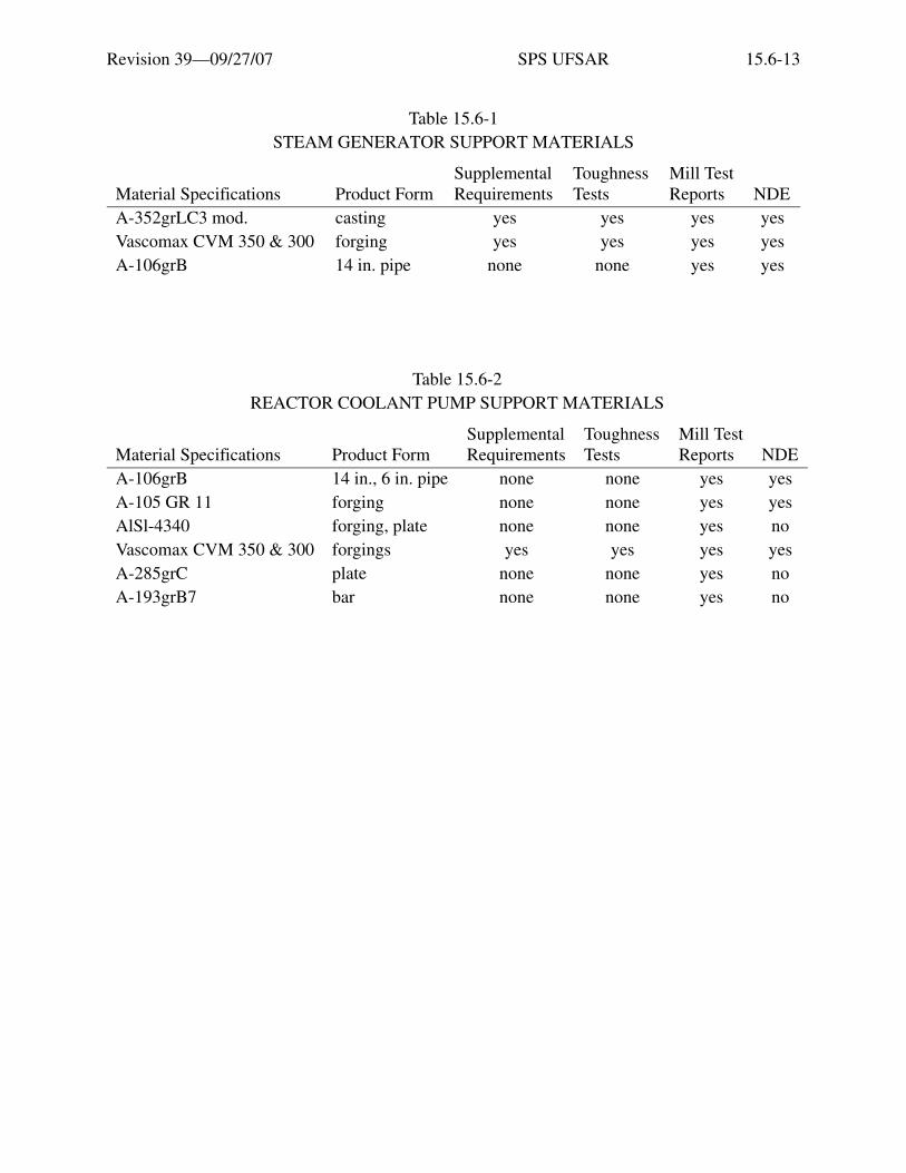
Revision 39—09/27/07 SPS UFSAR 15.6-13
Table 15.6-1STEAM GENERATOR SUPPORT MATERIALS
Material Specifications Product FormSupplementalRequirements
ToughnessTests
Mill TestReports NDE
A-352grLC3 mod. casting yes yes yes yesVascomax CVM 350 & 300 forging yes yes yes yesA-106grB 14 in. pipe none none yes yes
Table 15.6-2REACTOR COOLANT PUMP SUPPORT MATERIALS
Material Specifications Product FormSupplementalRequirements
ToughnessTests
Mill TestReports NDE
A-106grB 14 in., 6 in. pipe none none yes yesA-105 GR 11 forging none none yes yesAlSl-4340 forging, plate none none yes noVascomax CVM 350 & 300 forgings yes yes yes yesA-285grC plate none none yes noA-193grB7 bar none none yes no

Revision 39—09/27/07 SPS UFSAR 15.6-14
Table 15.6-3SUMMARY OF STRESS FOR FAILURE OF REACTOR COOLANT PUMP SUPPORT
DURING NORMAL OPERATION
Location Loop Stress (psi)Steam Generator Outlet A 20,291
B 17,388C 20,743
Reactor Vessel Inlet A 16,943B 18,337C 21,060
Crossover Leg A 21,940B 13,292C 20,196
Pressurizer Inlet C 32,728Material Properties (A376 Tp 316)
°F Syield Sult
100 30 ksi 75 ksi600 18.8 ksi 71.8 ksi650 18.5 ksi 71.8 ksi

Revision 39—09/27/07 SPS UFSAR 15.6-15
Figu
re15
.6-1
R
EA
CT
OR
NE
UT
RO
N S
HIE
LD
TA
NK
ASS
EM
BL
Y
Etia
m v
enen
atis
acc
umsa
n en
im. M
auris
rut
rum
, dia
m q
uis
tinci
dunt
ele
men
tum
, sem
orc
i bib
endu
m li
bero
, ut e
lem
entu
m
just
o m
agna
at a
ugue
. Aliq
uam
sap
ien
mas
sa, f
auci
bus
ac, e
lem
entu
m n
on, l
aore
et n
ec, f
elis
. Ves
tibul
um a
ccum
san
sagi
ttis
ipsu
m. I
n ul
lam
corp
er, d
ui s
ed c
ursu
s eu
ism
od, a
nte
wis
i dap
ibus
ligu
la, i
d rh
oncu
s ip
sum
mi a
t tel
lus.
Cla
ss a
pten
t ta
citi
soci
osqu
ad
litor
a to
rque
nt p
er c
onub
ia n
ostr
a, p
er in
cept
os h
ymen
aeos
. Qui
sque
rho
ncus
wis
i vita
e do
lor.
Etia
m
elei
fend
. Int
eger
impe
rdie
t veh
icul
a an
te. S
ed in
arc
u et
odi
o ac
cum
san
port
a. A
enea
n m
i. V
ivam
us n
on o
rci v
itae
urna
al
ique
t ulla
mco
rper
. Cla
ss a
pten
t tac
iti s
ocio
squ
ad li
tora
torq
uent
per
con
ubia
nos
tra,
per
ince
ptos
hym
enae
os. I
n fr
ingi
lla
ligul
a ve
l odi
o. In
hac
hab
itass
e pl
atea
dic
tum
st. E
tiam
tem
pus
lacu
s ac
arc
u. P
raes
ent n
on li
bero
.

Revision 39—09/27/07 SPS UFSAR 15.6-16
Figu
re15
.6-2
ST
EA
M G
EN
ER
AT
OR
SU
PPO
RT
ASS
EM
BL
Y
Etia
m v
enen
atis
acc
umsa
n en
im. M
auris
rut
rum
, dia
m q
uis
tinci
dunt
ele
men
tum
, sem
orc
i bib
endu
m li
bero
, ut e
lem
entu
m
just
o m
agna
at a
ugue
. Aliq
uam
sap
ien
mas
sa, f
auci
bus
ac, e
lem
entu
m n
on, l
aore
et n
ec, f
elis
. Ves
tibul
um a
ccum
san
sagi
ttis
ipsu
m. I
n ul
lam
corp
er, d
ui s
ed c
ursu
s eu
ism
od, a
nte
wis
i dap
ibus
ligu
la, i
d rh
oncu
s ip
sum
mi a
t tel
lus.
Cla
ss a
pten
t ta
citi
soci
osqu
ad
litor
a to
rque
nt p
er c
onub
ia n
ostr
a, p
er in
cept
os h
ymen
aeos
. Qui
sque
rho
ncus
wis
i vita
e do
lor.
Etia
m
elei
fend
. Int
eger
impe
rdie
t veh
icul
a an
te. S
ed in
arc
u et
odi
o ac
cum
san
port
a. A
enea
n m
i. V
ivam
us n
on o
rci v
itae
urna
al
ique
t ulla
mco
rper
. Cla
ss a
pten
t tac
iti s
ocio
squ
ad li
tora
torq
uent
per
con
ubia
nos
tra,
per
ince
ptos
hym
enae
os. I
n fr
ingi
lla
ligul
a ve
l odi
o. In
hac
hab
itass
e pl
atea
dic
tum
st. E
tiam
tem
pus
lacu
s ac
arc
u. P
raes
ent n
on li
bero
.
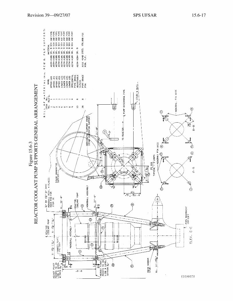
Revision 39—09/27/07 SPS UFSAR 15.6-17
Figu
re15
.6-3
R
EA
CT
OR
CO
OL
AN
T P
UM
P SU
PPO
RT
S G
EN
ER
AL
AR
RA
NG
EM
EN
T
Etia
m v
enen
atis
acc
umsa
n en
im. M
auris
rut
rum
, dia
m q
uis
tinci
dunt
ele
men
tum
, sem
orc
i bib
endu
m li
bero
, ut e
lem
entu
m
just
o m
agna
at a
ugue
. Aliq
uam
sap
ien
mas
sa, f
auci
bus
ac, e
lem
entu
m n
on, l
aore
et n
ec, f
elis
. Ves
tibul
um a
ccum
san
sagi
ttis
ipsu
m. I
n ul
lam
corp
er, d
ui s
ed c
ursu
s eu
ism
od, a
nte
wis
i dap
ibus
ligu
la, i
d rh
oncu
s ip
sum
mi a
t tel
lus.
Cla
ss a
pten
t ta
citi
soci
osqu
ad
litor
a to
rque
nt p
er c
onub
ia n
ostr
a, p
er in
cept
os h
ymen
aeos
. Qui
sque
rho
ncus
wis
i vita
e do
lor.
Etia
m
elei
fend
. Int
eger
impe
rdie
t veh
icul
a an
te. S
ed in
arc
u et
odi
o ac
cum
san
port
a. A
enea
n m
i. V
ivam
us n
on o
rci v
itae
urna
al
ique
t ulla
mco
rper
. Cla
ss a
pten
t tac
iti s
ocio
squ
ad li
tora
torq
uent
per
con
ubia
nos
tra,
per
ince
ptos
hym
enae
os. I
n fr
ingi
lla
ligul
a ve
l odi
o. In
hac
hab
itass
e pl
atea
dic
tum
st. E
tiam
tem
pus
lacu
s ac
arc
u. P
raes
ent n
on li
bero
.
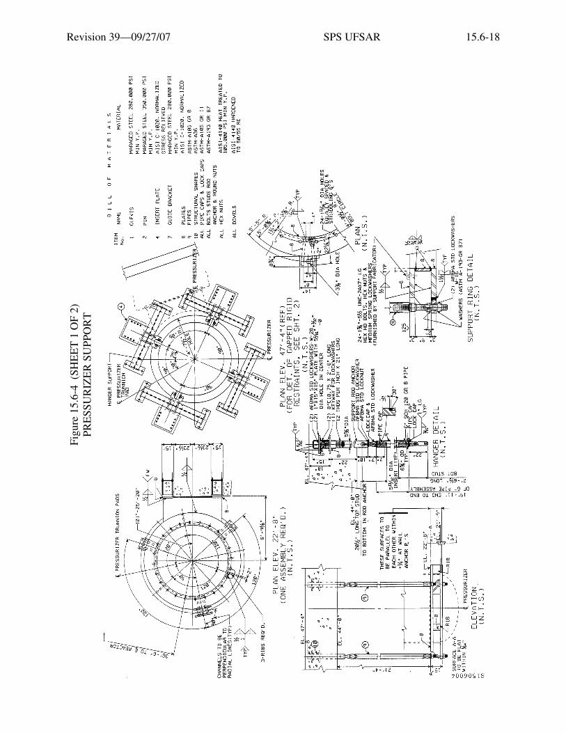
Revision 39—09/27/07 SPS UFSAR 15.6-18
Figu
re15
.6-4
(SH
EE
T 1
OF
2)PR
ESS
UR
IZE
R S
UPP
OR
T
Etia
m v
enen
atis
acc
umsa
n en
im. M
auris
rut
rum
, dia
m q
uis
tinci
dunt
ele
men
tum
, sem
orc
i bib
endu
m li
bero
, ut e
lem
entu
m
just
o m
agna
at a
ugue
. Aliq
uam
sap
ien
mas
sa, f
auci
bus
ac, e
lem
entu
m n
on, l
aore
et n
ec, f
elis
. Ves
tibul
um a
ccum
san
sagi
ttis
ipsu
m. I
n ul
lam
corp
er, d
ui s
ed c
ursu
s eu
ism
od, a
nte
wis
i dap
ibus
ligu
la, i
d rh
oncu
s ip
sum
mi a
t tel
lus.
Cla
ss a
pten
t ta
citi
soci
osqu
ad
litor
a to
rque
nt p
er c
onub
ia n
ostr
a, p
er in
cept
os h
ymen
aeos
. Qui
sque
rho
ncus
wis
i vita
e do
lor.
Etia
m
elei
fend
. Int
eger
impe
rdie
t veh
icul
a an
te. S
ed in
arc
u et
odi
o ac
cum
san
port
a. A
enea
n m
i. V
ivam
us n
on o
rci v
itae
urna
al
ique
t ulla
mco
rper
. Cla
ss a
pten
t tac
iti s
ocio
squ
ad li
tora
torq
uent
per
con
ubia
nos
tra,
per
ince
ptos
hym
enae
os. I
n fr
ingi
lla
ligul
a ve
l odi
o. In
hac
hab
itass
e pl
atea
dic
tum
st. E
tiam
tem
pus
lacu
s ac
arc
u. P
raes
ent n
on li
bero
.

Revision 39—09/27/07 SPS UFSAR 15.6-19
Figu
re15
.6-4
(SH
EE
T 2
OF
2)PR
ESS
UR
IZE
R S
UPP
OR
T
Etia
m v
enen
atis
acc
umsa
n en
im. M
auris
rut
rum
, dia
m q
uis
tinci
dunt
ele
men
tum
, sem
orc
i bib
endu
m li
bero
, ut e
lem
entu
m
just
o m
agna
at a
ugue
. Aliq
uam
sap
ien
mas
sa, f
auci
bus
ac, e
lem
entu
m n
on, l
aore
et n
ec, f
elis
. Ves
tibul
um a
ccum
san
sagi
ttis
ipsu
m. I
n ul
lam
corp
er, d
ui s
ed c
ursu
s eu
ism
od, a
nte
wis
i dap
ibus
ligu
la, i
d rh
oncu
s ip
sum
mi a
t tel
lus.
Cla
ss a
pten
t ta
citi
soci
osqu
ad
litor
a to
rque
nt p
er c
onub
ia n
ostr
a, p
er in
cept
os h
ymen
aeos
. Qui
sque
rho
ncus
wis
i vita
e do
lor.
Etia
m
elei
fend
. Int
eger
impe
rdie
t veh
icul
a an
te. S
ed in
arc
u et
odi
o ac
cum
san
port
a. A
enea
n m
i. V
ivam
us n
on o
rci v
itae
urna
al
ique
t ulla
mco
rper
. Cla
ss a
pten
t tac
iti s
ocio
squ
ad li
tora
torq
uent
per
con
ubia
nos
tra,
per
ince
ptos
hym
enae
os. I
n fr
ingi
lla
ligul
a ve
l odi
o. In
hac
hab
itass
e pl
atea
dic
tum
st. E
tiam
tem
pus
lacu
s ac
arc
u. P
raes
ent n
on li
bero
.

Revision 39—09/27/07 SPS UFSAR 15.6-20
Intentionally Blank

Revision 39—09/27/07 SPS UFSAR 15.7-1
15.7 MASONRY WALLS
Concrete masonry walls are used throughout the plant to provide barriers for radiationshielding, fire protection and personnel separation. Those walls utilized in the construction ofSeismic Class I structures are not designed or intended to act as bearing or for transmittingbuilding shear forces. These walls are not used as major load-bearing walls and are not includedas part of the overall building shear wall system.
All of the concrete masonry walls that are in proximity to or have attachments forsafety-related or equipment such that wall failure could affect a safety-related system wereidentified and analyzed in accordance with the requirements of IE Bulletin 80-11 (Reference 1).The reevaluation of the masonry walls was performed based upon criteria for reevaluatingconcrete masonry walls submitted in Reference 2, which uses as its acceptance criteria theallowable stresses specified in ACI-531-79, Building Code Requirements for Concrete MasonryStructures. Review of test data and the literature substantiates the use of these allowable stresses.The review also included research of acceptable damping percentages, analysis techniques,in-plane effects, arch action and local stress valves.
The reevaluation criteria considered loads from both safety- and non-safety-relatedattachments as well as relative interstory displacements between building elevations whereapplicable. All applicable loads and load combinations specified in the Surry FSAR for concretedesign were included in the reevaluation. A review of the walls determined that the walls are notsubjected to tornado missiles or depressurization, pipe whip or jet impingement loads. The globalreview of the walls included seismic inertia loads, interstory displacement loads for both in-planeand out-of-plane effects, equipment loads, and wind loads where applicable.
The local review included discontinuities such as openings and the mechanism for localload transfer into the walls. This included a review of potential local block pull out as well aspossible overstress within individual blocks due to attached equipment. Multiwythe walls werealso reviewed to ensure the integrity of the collar joint. Calculated shear and tension stressesacross the collar joints were compared against allowable values that were conservatively chosen toaccount for potential small areas of voids or other discontinuities.
At the completion of the response to IE Bulletin 80-11, all identified masonry block wallswere evaluated and, modified, as required, to meet the acceptance criteria. The results of thisreevaluation program were transmitted to the Nuclear Regulatory Commission. The analysisresults of the masonry wall reevaluation program indicated that of the walls requiring reanalysis,79 walls were acceptable, two walls were acceptable after equipment was removed from the wall,and 31 walls were modified to meet acceptance criteria. Seven safety-related masonry walls in thefuel building were not acceptable under extreme loading conditions and were replaced withblow-off siding. An additional 217 non-safety related walls were also reviewed to ensure that theydid not endanger safety-related equipment. Following the approval of responses to IEBulletin 80-11 by the Nuclear Regulatory Commission, all subsequent modifications involving

Revision 39—09/27/07 SPS UFSAR 15.7-2
masonry block walls are evaluated under the Nuclear Design Control Program, which continues toinvoke the technical requirements of IE Bulletin 80-11 (References 3 & 4).
15.7 REFERENCES
1. IE Bulletin 80-11, Masonry Wall Design, Nuclear Regulatory Commission, Office ofInspection and Enforcement, May 8, 1980.
2. Letter from B.R. Sylvia, VEPCO, to James P. O’Reilly, NRC. November 3, 1980, IE BulletinNo. 80-11 Interim Report, Surry Power Station Units 1 & 2, North Anna Power StationUnits 1 & 2, Serial No. 878.
3. Letter from Chandu P. Patel, NRC, Office of Nuclear Reactor Regulation, Masonry WallDesign, IE Bulletin 80-11 Surry Power Station Unit Nos. 1 and 3 (TAC Nos. 42867and 42868), August 11, 1988, Serial No. 88-551.
4. Letter from Bart C. Buckley, NRC, Office of Nuclear Reactor Regulation, Surry Units 1 and 2- Safety Evaluation Masonry Wall Design, IE Bulletin 80-11, (TAC Nos. 42867 and 42868),October 2, 1989.

Revision 39—09/27/07 SPS UFSAR 15A-i
Appendix 15ASeismic Design for the Nuclear Steam Supply System
and Miscellaneous Components

Revision 39—09/27/07 SPS UFSAR 15A-ii
Intentionally Blank

Revision 39—09/27/07 SPS UFSAR 15A-iii
Appendix 15A: Seismic Design for the Nuclear Steam Supply Systemand Miscellaneous Components
Table of Contents
Section Title Page
15A.1 GENERAL SEISMIC DESIGN CRITERIA FOR THE NUCLEARSTEAM SUPPLY SYSTEM . . . . . . . . . . . . . . . . . . . . . . . . . . . . . . . . . . . . . . . . . 15A-1
15A.2 SEISMIC DESIGN CRITERIA FOR PIPING, VESSELS, SUPPORTSAND REACTOR VESSEL INTERNALS . . . . . . . . . . . . . . . . . . . . . . . . . . . . . . . 15A-1
15A.2.1 Loading Condition Definitions . . . . . . . . . . . . . . . . . . . . . . . . . . . . . . . . . . . . . 15A-215A.2.1.1 Normal Conditions . . . . . . . . . . . . . . . . . . . . . . . . . . . . . . . . . . . . . . . . . . . . . 15A-215A.2.1.2 Upset Conditions . . . . . . . . . . . . . . . . . . . . . . . . . . . . . . . . . . . . . . . . . . . . . . 15A-215A.2.1.3 Emergency Conditions . . . . . . . . . . . . . . . . . . . . . . . . . . . . . . . . . . . . . . . . . . 15A-215A.2.1.4 Faulted Conditions . . . . . . . . . . . . . . . . . . . . . . . . . . . . . . . . . . . . . . . . . . . . . 15A-215A.2.2 Piping, Vessels, and Supports . . . . . . . . . . . . . . . . . . . . . . . . . . . . . . . . . . . . . . 15A-315A.2.3 Reactor Vessel Internals. . . . . . . . . . . . . . . . . . . . . . . . . . . . . . . . . . . . . . . . . . . 15A-415A.2.3.1 Design Criteria for Normal Operation . . . . . . . . . . . . . . . . . . . . . . . . . . . . . . 15A-415A.2.3.2 Design Criteria for Abnormal Operation . . . . . . . . . . . . . . . . . . . . . . . . . . . . 15A-4
15A.3 GENERAL ANALYTICAL PROCEDURE FOR SEISMIC DESIGN . . . . . . . . . 15A-415A.3.1 Mechanical Equipment . . . . . . . . . . . . . . . . . . . . . . . . . . . . . . . . . . . . . . . . . . . 15A-515A.3.2 Earthquake Experience-Based Method Developed for Unresolved
Safety Issue (USI) A-46 for Seismic Verification of Equipment . . . . . . . . . . . 15A-715A.3.3 Reactor Coolant Loops and Supports. . . . . . . . . . . . . . . . . . . . . . . . . . . . . . . . . 15A-815A.3.4 Anchor Bolts . . . . . . . . . . . . . . . . . . . . . . . . . . . . . . . . . . . . . . . . . . . . . . . . . . . 15A-1115A.3.5 Piping Systems. . . . . . . . . . . . . . . . . . . . . . . . . . . . . . . . . . . . . . . . . . . . . . . . . . 15A-1315A.3.5.1 Reanalysis Methods and Results . . . . . . . . . . . . . . . . . . . . . . . . . . . . . . . . . . 15A-1415A.3.5.2 Verification of Analysis Methods . . . . . . . . . . . . . . . . . . . . . . . . . . . . . . . . . 15A-1615A.3.5.3 Soil Structure Interaction . . . . . . . . . . . . . . . . . . . . . . . . . . . . . . . . . . . . . . . . 15A-18
15A.4 MOVEMENT OF REACTOR COOLANT SYSTEM COMPONENTS. . . . . . . . 15A-21
15A.5 TESTS TO DEMONSTRATE THE CONSERVATISM OF THELIMIT CURVES. . . . . . . . . . . . . . . . . . . . . . . . . . . . . . . . . . . . . . . . . . . . . . . . . . . 15A-23
15A.5.1 Westinghouse Topical Reports . . . . . . . . . . . . . . . . . . . . . . . . . . . . . . . . . . . . . 15A-2315A.5.2 Framatome Computer Programs (Unit 1 only) . . . . . . . . . . . . . . . . . . . . . . . . . 15A-2415A.5.2.1 BWSPAN . . . . . . . . . . . . . . . . . . . . . . . . . . . . . . . . . . . . . . . . . . . . . . . . . . . . 15A-2415A.5.2.2 BIJLAARD. . . . . . . . . . . . . . . . . . . . . . . . . . . . . . . . . . . . . . . . . . . . . . . . . . . 15A-2515A.5.2.3 FERMETURE . . . . . . . . . . . . . . . . . . . . . . . . . . . . . . . . . . . . . . . . . . . . . . . . 15A-2515A.5.2.4 SYSTUS . . . . . . . . . . . . . . . . . . . . . . . . . . . . . . . . . . . . . . . . . . . . . . . . . . . . . 15A-25

Revision 39—09/27/07 SPS UFSAR 15A-iv
Appendix 15A: Seismic Design for the Nuclear Steam Supply Systemand Miscellaneous ComponentsTable of Contents (continued)
Section Title Page
15A.5.2.5 RCCM-ASME . . . . . . . . . . . . . . . . . . . . . . . . . . . . . . . . . . . . . . . . . . . . . . . . 15A-25
15A References. . . . . . . . . . . . . . . . . . . . . . . . . . . . . . . . . . . . . . . . . . . . . . . . . . . . . . . . 15A-25
Revision 39—09/27/07 SPS UFSAR 15A-v
Table 15A-1 Loading Conditions and Stress Limits . . . . . . . . . . . . . . . . . . . . . . . . . . . . . 15A-31Table 15A-2 Minimum Margins of Safety . . . . . . . . . . . . . . . . . . . . . . . . . . . . . . . . . . . . 15A-33Table 15A-3 Tests and Test Results on SA 106B Carbon Steel Pipe Specimens
(Internal Pressurization = 3000 psia) . . . . . . . . . . . . . . . . . . . . . . . . . . . . . . 15A-34Table 15A-4 Tests and Test Results on 304 Stainless Steel Specimens
(Internal Pressurization = 3000 psia) . . . . . . . . . . . . . . . . . . . . . . . . . . . . . . 15A-35Table 15A-5 Level of Stress as a Percentage of Code Allowable Stress . . . . . . . . . . . . . 15A-36Table 15A-6 Factors of Safety for Component Supports Under Design-Basis Seismic
and Normal Operating Loads Surry Units 1 and 2. . . . . . . . . . . . . . . . . . . . 15A-37Table 15A-7 Factors of Safety for Component Supports Under Combined
Accident Loads Surry Units 1 and 2 . . . . . . . . . . . . . . . . . . . . . . . . . . . . . . 15A-38
Appendix 15A: Seismic Design for the Nuclear Steam Supply Systemand Miscellaneous Components
List of Tables
Table Title Page

Revision 39—09/27/07 SPS UFSAR 15A-vi
Figure 15A-1 Envelope for 0.5% Damping Ground ResponseSpectra-Average Gmax . . . . . . . . . . . . . . . . . . . . . . . . . . . . . . . . . . . . . . . . 15A-39
Figure 15A-2 Envelope for 0.5% Damping Ground ResponseSpectra-Average Gmax + 50%. . . . . . . . . . . . . . . . . . . . . . . . . . . . . . . . . . . 15A-40
Figure 15A-3 Envelope for 0.5% Damping Ground ResponseSpectra-Average Gmax -50%. . . . . . . . . . . . . . . . . . . . . . . . . . . . . . . . . . . . 15A-41
Figure 15A-4 Design Limits Compared to Experimental Points,SA 106B Carbon Steel . . . . . . . . . . . . . . . . . . . . . . . . . . . . . . . . . . . . . . . . 15A-42
Figure 15A-5 Design Limits Compared to Experimental Points, 304 Stainless Steel . . . 15A-43Figure 15A-6 Typical Stress-Strain Curve, 304 Stainless Steel . . . . . . . . . . . . . . . . . . . . 15A-44Figure 15A-7 Typical Stress-Strain Curve, Inconel 600 . . . . . . . . . . . . . . . . . . . . . . . . . . 15A-45Figure 15A-8 Typical Stress-Strain Curve, SA 302 Grade B . . . . . . . . . . . . . . . . . . . . . . 15A-46
Appendix 15A: Seismic Design for the Nuclear Steam Supply Systemand Miscellaneous Components
List of Figures
Figure Title Page

Revision 39—09/27/07 SPS UFSAR 15A-1
Appendix 15ASEISMIC DESIGN FOR THE NUCLEAR STEAM SUPPLY SYSTEM
AND MISCELLANEOUS COMPONENTS
15A.1 GENERAL SEISMIC DESIGN CRITERIA FOR THE NUCLEAR STEAM SUPPLY SYSTEM
This Appendix is based on Appendix B to the initial FSAR.
All Class I components of the nuclear steam supply system are designed in accordance withthe following criteria:
1. Primary operating stresses, when combined with the operating-basis earthquake seismicstresses resulting from a dynamic analysis using a response spectrum normalized to amaximum horizontal ground acceleration of 0.07g and a simultaneous vertical groundacceleration of two-thirds the horizontal, are maintained within the allowable stress limits inTable 15A-1.
2. Primary operating stresses when combined with the design-basis earthquake seismic stressesresulting from a dynamic analysis using a response spectrum normalized to a maximumhorizontal ground acceleration of 0.15g and a simultaneous vertical ground acceleration oftwo-thirds of the horizontal, are limited so that the function of the component or system shallnot be impaired, preventing a safe and orderly shutdown of the unit. Further, the primaryoperating stresses are maintained within the allowed stress limits in Table 15A-1.
“No loss of function” requires that rotating equipment will not seize, pressure vessels willnot rupture, and supports will not collapse or deform to such a degree as to cause failure ofthe supported equipment. In addition, systems required to be leaktight will remain leaktight,and engineered safeguards will perform intended functions.
15A.2 SEISMIC DESIGN CRITERIA FOR PIPING, VESSELS, SUPPORTS AND REACTOR VESSEL INTERNALS
Following discussions with the Staff of the Atomic Energy Commission (AEC) Division ofReactor Licensing during the Construction Permit Application Review for Diablo Canyon Unit 1,the criteria presented in WCAP-5890, Revision 1 (Reference 1), for the generation of limit curveswere modified. Details of the manner in which this modification was developed are given inSection 15A.5.1.
The loading conditions employed in the design of Class I piping, vessels, and supports areenumerated and defined in Section 15A.2.1. The allowable stress limits associated with thevarious loading conditions are shown in Table 15A-1. Since the reactor vessel internals must also

Revision 39—09/27/07 SPS UFSAR 15A-2
satisfy deformation limits to be able to perform their function, i.e., allow core shutdown andcooling, the vessel internals are discussed separately in Section 15A.2.3.
15A.2.1 Loading Condition Definitions
The loading condition definitions given below are taken from Section III of the ASMEBoiler and Pressure Vessel Code, Summer 1968 Addenda.
15A.2.1.1 Normal Conditions
Any condition in the course of system start-up, operation in the design power range, andsystem shutdown, in the absence of upset, emergency or faulted conditions.
15A.2.1.2 Upset Conditions
Upset conditions are any deviations from normal conditions anticipated to occur oftenenough that design should include a capability to withstand the conditions without operationalimpairment. The upset conditions include those transients which result from any single operatorerror or control malfunction, transients caused by a fault in a system component requiring itsisolation from the system, transients due to loss of load or power, and any system upset notresulting in a forced outage. The estimated duration of an upset condition shall be included in thedesign specifications. The upset conditions include the effect of the operating-basis earthquake forwhich the system must remain operational or must regain its operational status.
15A.2.1.3 Emergency Conditions
Any deviations from normal conditions which require shutdown for correction of theconditions or repair of damage in the system. The conditions have a low probability of occurrencebut are included to provide assurance that no gross loss of structural integrity will result as aconcomitant effect of any damage developed in the system.
15A.2.1.4 Faulted Conditions
Those combinations of conditions associated with extremely low probability postulatedevents whose consequences are such that the integrity and operability of the nuclear energysystem may be impaired to the extent where considerations of public health and safety areinvolved. Such considerations require compliance with safety criteria as may be specified byjurisdictional authorities. Among the faulted conditions may be a specified design-basisearthquake for which safe shutdown is required.

Revision 39—09/27/07 SPS UFSAR 15A-3
15A.2.2 Piping, Vessels, and Supports
The reasons for selection of the above-mentioned loading conditions and allowable stresslimits are as follows:
1. When subjected to the operating-basis earthquake, the nuclear steam supply system isdesigned to be capable of continued safe operation. Equipment and supports needed for thispurpose are required to operate within normal design limits, as shown in Table 15A-1. Theload combination corresponding to the upset loading condition is the normal load, plus theoperating-basis earthquake load.
2. In the case of the design-basis earthquake, it is necessary to ensure that components requiredto shut the unit down and maintain it in a safe shutdown condition do not lose their capabilityto perform their safety function. This capability is ensured by maintaining the emergencystress limits as shown in Table 15A-1.
3. For the highly unlikely but postulated case of pipe rupture, a reactor coolant branch or otherpotentially governing break, the effects of the pipe rupture will not cause failure propagationto the reactor coolant piping. The load combination corresponding to the faulted loadingcondition is the design-basis earthquake and/or design-basis accident load.
4. For the extremely remote event of simultaneous occurrence of a design-basis earthquake andpostulated pipe rupture of a reactor coolant system branch line or other potentiallycontrolling break, the Class I piping and component are checked for no loss of function, i.e.,the capability to contain fluid, allow fluid flow, and perform vital engineered safeguardsfunctions. This is ensured by limiting the various stress combinations within the faultedcondition design limits shown in Table 15A-1.
The minimum margin of safety between the design limit stress and the expected collapsecondition is for the case of pure tension, and is defined as:
Under more realistic operating conditions, piping and vessels will always experience somecombination of tension and bending. For these combined load cases, the margin of safety isgreater than that for pure tension, as shown by the limit curves contained in WCAP-5890, Rev. 1,and shown in Figures 15A-4 and 15A-5. Therefore, it is conservative to base the margin of safetyon pure tension. Table 15A-2 illustrates the margin of safety between the stress limits for variousload conditions and the expected failure or collapse condition for typical materials.
Plastic or limit analyses conducted within the limits of the faulted condition were performedconsidering plastic material behavior, including, as required, modifications of material stiffnesscharacteristics, formation of plastic hinges and other non-linear effects, as determined in detailedstructural analysis, and provided in standard stress reports.
Sultimate - SdesignSdesign
------------------------------------------

Revision 39—09/27/07 SPS UFSAR 15A-4
15A.2.3 Reactor Vessel Internals
15A.2.3.1 Design Criteria for Normal Operation
The internals and core are designed for normal operating conditions and subjected to loadsof mechanical, hydraulic, and thermal origin. The response of the structure under theoperating-basis earthquake is included in this category as well as operational transients (upsetconditions).
The stress criteria established in Section III of the ASME Boiler and Pressure Vessel Code,Article 4, have been adopted as a guide for the design of the internals and core, with the exceptionof those fabrication techniques and materials not covered by the Code, such as the fuel rodcladding. Seismic stresses are combined in the most conservative way and are considered primarystresses.
The members are designed under the basic principles of: (1) maintaining deflections withinacceptable limits, (2) keeping the stress levels within acceptable limits, and (3) preventing fatiguefailures.
15A.2.3.2 Design Criteria for Abnormal Operation
The abnormal design condition assumes blowdown effects due to a pipe break1 combined(by SRSS combination) in the most unfavorable manner with the effects associated with thedesign-basis earthquake.
For this condition, the criteria for acceptability are that the reactor is capable of safeshutdown and that the engineered safety features are able to operate as designed. Consequently,the limitations established on the internals for these types of loads are concerned principally withthe maximum allowable deflections. Additional stress criteria for critical structures under normaloperation, plus the design-basis earthquake and blowdown excitation, ensure that the structuralintegrity of the components is maintained.
15A.3 GENERAL ANALYTICAL PROCEDURE FOR SEISMIC DESIGN
The design and analysis of Class I components of the nuclear steam supply system utilizesthe “response spectrum” approach.
The dynamic analysis is performed using the normal mode methods. The inertial propertiesof the models are characterized by the mass and mass moment of inertia of each mass point. Thestiffness properties are characterized by the moment of inertia, area, shear shape factor, torsionconstant, Young’s modulus, and shear modulus.
1. As discussed in Section 15.6.2, it is no longer necessary to consider the dynamic effects of a postulated rupture of the primary reactor coolant loop piping. However, pipe ruptures of reactor coolant branchlines are still postulated.
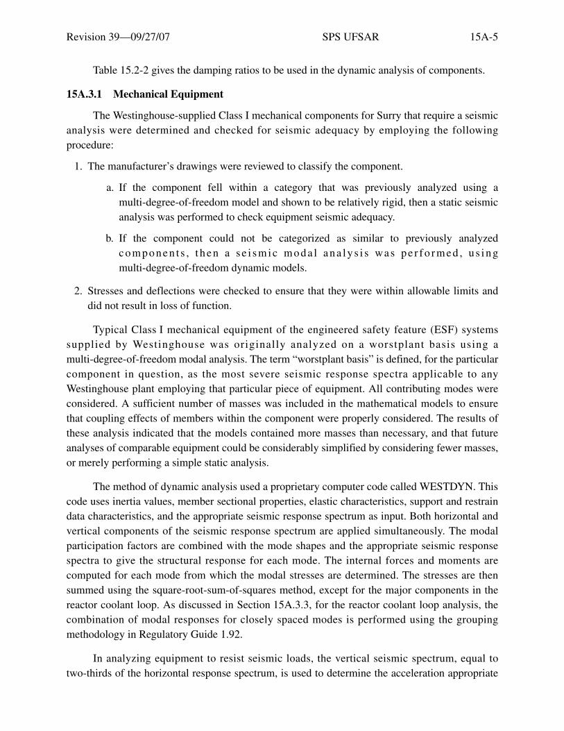
Revision 39—09/27/07 SPS UFSAR 15A-5
Table 15.2-2 gives the damping ratios to be used in the dynamic analysis of components.
15A.3.1 Mechanical Equipment
The Westinghouse-supplied Class I mechanical components for Surry that require a seismicanalysis were determined and checked for seismic adequacy by employing the followingprocedure:
1. The manufacturer’s drawings were reviewed to classify the component.
a. If the component fell within a category that was previously analyzed using amulti-degree-of-freedom model and shown to be relatively rigid, then a static seismicanalysis was performed to check equipment seismic adequacy.
b. If the component could not be categorized as similar to previously analyzedcomponen t s , t hen a s e i smic moda l ana ly s i s was pe r fo rmed , u s ingmulti-degree-of-freedom dynamic models.
2. Stresses and deflections were checked to ensure that they were within allowable limits anddid not result in loss of function.
Typical Class I mechanical equipment of the engineered safety feature (ESF) systemssupplied by Westinghouse was originally analyzed on a worstplant basis using amulti-degree-of-freedom modal analysis. The term “worstplant basis” is defined, for the particularcomponent in question, as the most severe seismic response spectra applicable to anyWestinghouse plant employing that particular piece of equipment. All contributing modes wereconsidered. A sufficient number of masses was included in the mathematical models to ensurethat coupling effects of members within the component were properly considered. The results ofthese analysis indicated that the models contained more masses than necessary, and that futureanalyses of comparable equipment could be considerably simplified by considering fewer masses,or merely performing a simple static analysis.
The method of dynamic analysis used a proprietary computer code called WESTDYN. Thiscode uses inertia values, member sectional properties, elastic characteristics, support and restraindata characteristics, and the appropriate seismic response spectrum as input. Both horizontal andvertical components of the seismic response spectrum are applied simultaneously. The modalparticipation factors are combined with the mode shapes and the appropriate seismic responsespectra to give the structural response for each mode. The internal forces and moments arecomputed for each mode from which the modal stresses are determined. The stresses are thensummed using the square-root-sum-of-squares method, except for the major components in thereactor coolant loop. As discussed in Section 15A.3.3, for the reactor coolant loop analysis, thecombination of modal responses for closely spaced modes is performed using the groupingmethodology in Regulatory Guide 1.92.
In analyzing equipment to resist seismic loads, the vertical seismic spectrum, equal totwo-thirds of the horizontal response spectrum, is used to determine the acceleration appropriate

Revision 39—09/27/07 SPS UFSAR 15A-6
to the vertical frequency. An idealized umbrella spectrum was used in the analyses. The floorresponse spectra at the Surry site are encompassed by the umbrella spectrum used in the dynamicanalysis of Westinghouse-supplied equipment.
Typical Class I engineered safeguards tanks supplied by Westinghouse, e.g., for boric acid,accumulator, and boron injection, were analyzed using the method above, with the combinedhorizontal and vertical seismic excitation occurring simultaneously in conjunction with normalloads. Hydrodynamic analyses of these tanks have been performed using the methods described inTID 7024 (Reference 2).
Selected critical Class I ESF valves supplied by Westinghouse have been analyzed using theabove method, and the results indicate that their fundamental natural frequency is sufficientlyseparated from the building frequency. The results indicate that the total stress, considering allmodes, is far below the allowable stress limit. Motors attached to motor-operated valves havebeen included in the mathematical models.
The deflections and stresses obtained from the seismic analysis are added to the deflectionsand stresses associated with the operational mode of the mechanical equipment to verify thatclearances are not exceeded and the stresses are within allowable limits. This criterion ensuresthat this equipment will perform the intended function under seismic conditions.
All mechanical equipment analyzed had fundamental modes in the rigid range, with theexception of loop stop valves and some vertical tanks.
The fundamental frequency of vertical tanks and the loop stop valves was greater than 9 Hz,which is outside the resonance range of the structures in which they are housed. The componentsupports were modified to remove the fundamental frequency of the item from the resonancerange of the structure, by providing stiffer supports to increase the fundamental frequency of thecomponent. The selection of the type of restraint used was dependent upon the componentanalyzed and the structure surrounding the component.
Restraints, snubbers, or other devices are not used to preclude resonance of the electricaland control systems equipment for seismic loading. Protection system equipment that is typical ofthe design has been subject to tests under simulated seismic accelerations to demonstrate theability to perform and complete its function. These data are contained in WCAP-7397-L(Reference 3).
The seismic loads for the design and analysis of Class I mechanical components, includingpumps, valves, heat exchangers, and tanks within Stone & Webster’s scope of responsibility, werebased on the ground response spectra (GRS) shown in Figures 2.5-5 and 2.5-6 or amplified floorresponse spectra (ARS), depending on their location. Seismic loads were developed for theoperating-basis earthquake (OBE) and the design-basis earthquake (DBE). The spectra used in theevaluation of Class I mechanical components were based on damping values consistent with those

Revision 39—09/27/07 SPS UFSAR 15A-7
indicated in Table 15.2-2. Where applicable, seismic loads were combined with the results fromother load cases such as thermal and dead load. Constraints such as snubbers or other appropriatedevices are utilized wherever necessary to meet design requirements.
All Class I mechanical components are designed to withstand the operating-basisearthquake and to function through the design-basis earthquake to safe shutdown. Vendorssupplying the components are required by specification to design the components to function, asoutlined above, under the seismic loadings. The vendor is required to validate component integrityunder the specified seismic conditions.
15A.3.2 Earthquake Experience-Based Method Developed for Unresolved Safety Issue (USI) A-46 for Seismic Verification of Equipment
In response to U.S. Nuclear Regulatory Commission Generic Letter 87-02 on USI A-46,Verification of Seismic Adequacy of Mechanical and Electrical Equipment in Operating Reactors,a Generic Implementation Procedure (GIP) was developed by the Seismic Qualification UtilitiesGroup (SQUG). The criteria and methodology in Revision 3 of the GIP (Reference 40), asmodified and supplemented by the NRC Supplemental Safety Evaluation Reports (SSERs) 2and 3 (References 44 & 45) may be used, with certain additional considerations, as an alternativeto other licensing basis methods for seismic design and verification of existing, modified, new andreplacement equipment classified as safety-related, NSQ or seismic category 1. Considerationsthat are additional to the GIP pertain to the following issues:
• Use of GIP Method A for estimating seismic demand.
• Additional criteria applicable for the design and analysis of new flat bottom verticaltanks.
• Applicability of Part II, Section 5 of the GIP for conduit and cable tray raceways.
• Use of criteria associated with damping values, static coefficient and expansion anchorsafety factors for equipment anchorage evaluations conforming to the current,conservative, licensing basis commitments.
• Documentation of the results of the Screening Verification and Walkdown in Section 4.6of the GIP may be limited to the use of walkdown checklists. It is not necessary tocomplete the Screening Verification Data Sheets (SVDS).
• It is not necessary to identify “essential relays” and perform functionality screening asdefined in Section 6 of the GIP. Relays designated as Class 1E are evaluated bycomparing seismic capacity to seismic demand.
• The GIP method is generally applicable only for equipment located in mild environment.However, with case-by-case justification, it may be used for equipment in harshenvironment.
Revision 39—09/27/07 SPS UFSAR 15A-8
Guidance for the use of the GIP for the seismic design and verification of mechanical andelectrical equipment, including a discussion of the above exceptions, is provided in engineeringprocedures (References 62 & 63).
15A.3.3 Reactor Coolant Loops and Supports
The original configuration of the reactor coolant system equipment supports included tenlarge-bore hydraulic snubbers per loop to carry the loads from postulated pipe ruptures of thereactor coolant system, main steam line, and feedwater line. Subsequent fracture mechanicsanalyses, submitted to the NRC on behalf of the Westinghouse Owners Group, demonstrated thatthe probability of rupture of the primary coolant loop is extremely small, and that the presence ofa pipe crack could be detected by leakage well before the crack grew to a critical size whichwould cause rupture. NRC Generic Letter 84-04 (Reference 4) provided the NRC staff safetyevaluation of these “leak-before-break” analyses, concluding that, provided certain specificconditions are met, the dynamic effects of a postulated pipe break in the reactor coolant systemprimary loop need not be considered as a design basis for the reviewed plants, including SurryUnits 1 and 2. Subsequently, Generic Letter 87-11 (Reference 5) eliminated the need to postulateArbitrary Intermediate Breaks and allowed removal of the associated pipe whip restraints and jetimpingement shields. Because the stresses in the main steam lines inside containment are wellbelow the stress criteria for required mandatory intermediate breaks, the only breaks which needbe postulated are terminal end breaks which do not apply lateral loads to the steam generator.Based on the relief provided by these two relaxations of criteria, the reactor coolant systemsupports have been modified to eliminate eight of the ten large-bore snubbers per loop of thereactor coolant system. These efforts are discussed in Section 15.6.2; additional information iscontained in References 6-15.
The reactor coolant loop system was re-evaluated with the snubbers eliminated to assurethat the conditions of pressure, deadweight, thermal, seismic, and remaining pipe rupture effects,would not result in unacceptable stress levels or factors of safety. Two essentially independentanalyses of a representative single primary loop were performed by Westinghouse ElectricCorporation and Stone & Webster Engineering Corporation, in accordance with the originaldivision of design responsibilities. Westinghouse performed deadweight, pressure, thermal andseismic analyses using a simplified model as the run of record to obtain piping stresses. Stone &Webster performed analyses using a model incorporating a detailed representation of the supportmembers, principally to obtain component support loads under normal and accident loadings.Both analytical and models were revisions to existing models and incorporated changes due to thesteam generator replacements as well as the snubber elimination efforts.
These analyses incorporated the loads from deadweight, internal pressure, thermalexpansion, seismic events (OBE and DBE), and the dynamic effects of pipe ruptures of othersystems (controlling breaks, for example), in the main steam line, pressurizer surge line, mainfeedwater line, etc.) No other hydraulic transient loading was considered as significant.

Revision 39—09/27/07 SPS UFSAR 15A-9
For seismic analysis, the soil structure interaction amplified response spectra for 0.5 percentcritical equipment damping (OBE) and 1 percent equipment damping (DBE) were used withappropriate “bump” factors as discussed in Section 15A.3.5.3. These damping values are lowerthan those in Regulatory Guide 1.61, Damping Values for Seismic Design of Nuclear PowerPlants and in ASME Code Case N-411, Alternative Damping Values for Seismic Analysis ofClasses 1, 2, and 3 Piping. The vertical and horizontal earthquake responses were combined forpiping analysis as described in Section 15A.3.3. For component support analysis, the responses tothe three directions of earthquake loading were combined by SRSS. The combination of modalresponses for closely spaced modes was performed using the grouping methodology inRegulatory Guide 1.92.
The Westinghouse analysis used the WESTDYN code and a simplified representation of thecomponent supports as stiffness matrices. The component support stiffness matrices weresupplied by Stone & Webster. The WESTDYN computer code has been utilized on numerousWestinghouse plants, and was reviewed and found acceptable by the NRC for the Surry units in1974. A detailed description of the WESTDYN method of analysis is given below.
The code uses as input system geometry, inertia values, member sectional properties, elasticcharacteristics, support and restraint data characteristics, and the appropriate Surry seismicresponse spectrum of 0.5% critical damping. Both horizontal and vertical components of theseismic response spectrum are applied simultaneously.
With these input data, the overall stiffness matrix [K] of the three-dimensional pipingsystem is generated (including translational and rotational stiffness). Restraints are deleted, andthe stiffness matrix is inverted to give the flexibility matrix [F] of the system.
[F] = [K]-l
A product matrix is formed by the multiplication of the flexibility and mass matrices. Thisproduct matrix forms the dynamic matrix [D] from which the modal matrix is computed.
[D] = [F] [M]
The modal spectral matrices are generated using a modified Jacobi method.
(ω2 [M] - [K]) X = O
From this information, the modal participation factor is combined with the mode shapes andthe appropriate seismic response spectra to give the structural response for each mode.
The Stone & Webster analysis used the STARDYNE computer code and a modelincorporating a detailed representation of the support members. STARDYNE is a public domaincomputer program and is recognized as a Category 1 computer program suitable for nuclear

Revision 39—09/27/07 SPS UFSAR 15A-10
safety-related work. The program used is maintained under Stone & Webster’s Quality Controlprocedures. The following modules of STARDYNE, Version 3, Level H, were used:
• STAR (Static and Modal Extraction Analysis)
• DYNRE4 (Seismic Response Spectrum Analysis)
• DYNRE6 (Time History Transient Analysis)—used only for evaluating pipe ruptureloadings
Dynamic analyses were performed of the controlling pipe ruptures in the pressurizer surgeline, main steam line, and main feedwater lines. The originally-postulated terminal andintermediate breaks were reviewed by Stone & Webster to determine those breaks which wouldcause the most severe loadings on the revised support configuration with snubbers removed.Time-history forcing functions were applied to the detailed model representing these potentiallylimiting breaks, to obtain maximum member loads with the revised support configuration. Theseloads were combined by SRSS with the seismic DBE loads and then summed with deadweightand pressure loads.
The results of the two independent analyses with revised support configuration establishedthat the frequencies of most vibrational modes are virtually unchanged by the snubbereliminations. Comparison of the interface loads calculated by the two models was performed toensure that the results of the two models were consistent; the significant interface loads werefound to be within 15%, which is considered to be good agreement. The analyses demonstratedthat the piping components and supports are stressed within acceptable limits, and adequate safetymargins exist in a seismic event. The maximum level of stress (percentage) compared to the Codeallowable at the highest stress point in each leg of the reactor coolant loop for thermal,deadweight, and seismic conditions are given in Table 15A-5.
In addition, the maximum resultant bending moment in the primary coolant loop pipingunder combined deadweight, pressure, thermal, and design basis seismic loadings is28,860 inch-kips. This value is less than the enveloped value in the Westinghouse topical report,WCAP-9558, Revision 2 (Reference 6), and also less than 42,000 inch-kips which was identifiedin NRC Generic Letter 84-04 as the maximum allowable moment for the Westinghouse Owner’sGroup plants for justifying that pipe rupture need not be postulated in the primary reactor coolantloop piping.
For combined normal operating and seismic loads, the location of the maximum stress is thesteam generator outlet elbow; for the main steam line rupture loading, the location of maximumstress is in the steam generator inlet elbow; for the pressurizer surge line break, the maximumstress occurs in the hot leg where the surge line intersects.

Revision 39—09/27/07 SPS UFSAR 15A-11
Stone & Webster evaluated the calculated maximum loadings on the supports of themodified support configuration with eight of the large-bore snubbers eliminated. The factors ofsafety (allowable load/combined load) for the combined deadweight, pressure, thermal, anddesign basis seismic loads are given in Table 15A-6. Similar factors of safety under the combineddeadweight, pressure, thermal, and SRSS combination of design basis seismic loads plusmaximum pipe rupture loads, are given in Table 15A-7. These tables demonstrate that adequatefactors of safety exist under all loading conditions.
The results of these analyses confirm that the large-bore snubber eliminations do notcompromise the bases for the previous leak-before-break analysis, namely:
1. The loading on the primary loop piping is still enveloped by the generic analyses submittedon behalf of the A-2 Owners Group and accepted by the NRC staff in Generic Letter 84-04,and specifically for Surry by NRC letter dated June 16, 1986; and
2. The reactor coolant system equipment, piping, and supports continue to have acceptablemargins of safety under licenced loading conditions other than the now-eliminated rupturesof the primary loop piping and Arbitrary Intermediate Break of the main steam lines.
The inertial forces and moments are computed for each mode from which the modalstresses are determined. The stresses are then summed using the square-root-sum-of-squaresmethod.
The maximum stresses in the reactor coolant loop piping imposed by the normal loads plusloads associated with the design-basis earthquake are below the allowable stress limit. The stresslevels in the reactor coolant loop piping provided in References 9 and 11 remain valid.
15A.3.4 Anchor Bolts
The majority of anchor bolts originally installed at the Surry Power Station were shell-typePhillips self-drilling anchors. A minimum safety factor of four was used. Cyclic loads and theeffect of baseplate flexibility were not specifically considered; however, supports, baseplates, andanchor bolts were designed to withstand the maximum force exerted by seismic and thermalconditions.
In response to IE Bulletin 79-02 (Reference 16), all pipe support baseplates were analyzedconsidering baseplate flexibility, and modifications were made when baseplates and/or anchorbolts were found inadequate. Wedge-type Hilti bolts were installed in accordance withmanufacturer’s requirements based on onsite testing conducted by Hilti, Inc.
A finite element analysis was performed using the ANSYS computer program as providedby an owner’s group organized by Teledyne Engineering Services. A description of this programwas submitted to the NRC as Technical Report TR-3501-1, Revision 1 (Reference 17). In somecases where the support plate could not be modeled in the computer program, hand calculationswere performed, allowing sufficient margin for baseplate flexibility and prying action.
Revision 39—09/27/07 SPS UFSAR 15A-12
The factors of safety of four for wedge-type anchors and five for shelltype anchors wereused to determine the anchor bolt allowable loads for the reanalysis. All baseplates werereanalyzed to ensure that these factors of safety were met. Where the factors of safety were notmet by analysis, modifications were provided to ensure the appropriate factor of safety. Theoriginal design for anchor bolts at Surry was based on a factor of safety of four for all anchorbolts, based on a design concrete strength of 3000 psi. In conjunction with IE Bulletin 79-02, aconcrete inspection program was performed to demonstrate a concrete strength of 4000 psi, whichwould provide the factor of safety of five required by the Bulletin. Thirty-two Windsor probe testswere performed at various locations throughout the plant (Surry Units 1 and 2) to provide data forthe evaluation. The results of this program show a 95% confidence level of at least 4000 psiconcrete. Therefore, the analysis was based on 4000 psi concrete with the factors of safety of fourand five required by Bulletin 79-02.
No special design requirements for the anchor bolts to withstand cyclic loads were applied.Testing performed for the owner’s group, the results of which are presented in Technical ReportTR-3501-1 indicates that cyclic loading on the anchors does not result in a general reduction ofthe ultimate capacity of the anchor. Bolts for shell-type anchors (Phillips Red-Head self-drillinganchors) were tightened snugly, but were not preloaded. Wedge anchors (Hilti bolts) werepreloaded to the design allowable load.
To ensure that the design requirements have been met for the installed anchor bolts, aninspection and testing program was conducted. Under this program, one anchor bolt peraccessible base plate was inspected and tension tested to at least the anchor bolt design load.Anchor bolt installations which were suspect based on the visual inspection were tension tested toat least the anchor bolt design allowable load (20% of the manufacturer’s ultimate) and evaluatedfor a factor of safety of five by tension testing to five times the design load, or determining theanchor capacity based on the results of the visual inspection. When the anchor was found to beinadequate as a result of the evaluation, or of slippage greater than 1/16 inch under the tensiontest, the baseplate was reanalyzed with that bolt missing. The remaining bolts on the baseplatewere inspected and tested for adequacy under the higher redistributed load when the reanalysiswas acceptable, or for the original design load when the loads could not be redistributed.Inspection and test results showed that 97% of the baseplates were acceptable. All anchor boltsthat were inadequate or damaged were replaced to ensure adequacy of the anchorage system.
In order to evaluate operability of each Seismic Category I piping system, the anchor boltinspection and test results were recorded on a system basis. The system designations shown inTable 15.2-1 were used in conjunction with a QA Category I piping line table to determinesystems for Bulletin 79-02 purposes. Of the 14 systems for which anchor bolt inspections wereperformed, 12 of the systems had acceptance percentages greater than 95%. The acceptancepercentages for the other two systems, the reactor coolant system and the residual heat removalsystem, were 94.7% and 92.1%, respectively. All systems with baseplates inaccessible for bolt

Revision 39—09/27/07 SPS UFSAR 15A-13
inspection and testing had remote visual inspections performed to ensure that all anchor boltswere present and no gross deficiencies existed. For the two systems with less than 95%acceptance, the inaccessible baseplates were further evaluated to ensure high design factors ofsafety greater than those required by the Bulletin. Review of the baseplates where anchor boltswere found to be inadequate did not indicate any common characteristic (i.e., floor plates, wallplates, or ceiling plates) which would necessitate further inspection and testing of the inaccessiblebaseplates with a particular characteristic.
Piping systems 2 in. in diameter or less were originally designed by a chart analysis method.To ensure adequacy of the baseplates and anchor bolts in justifying operability of the small-borepiping, a sampling program was initiated. Five 2-inch lines were selected as representative of thesmall bore piping. Three safety injection lines and two chemical volume and control lines, whichhave a total of 22 supports with 43 baseplates, were analyzed in this effort. Baseplate analysisefforts show anchor bolt factors of safety ranging from 5.2 to 638, with the majority of anchorbolts having design factors of safety above 60.
Seventy-three anchor bolts on 12 of the small-bore baseplates were inspected and tensiontested. Sixty-eight of these anchor bolts (93%) were accepted. The baseplates for the five rejectedanchors were reanalyzed with the discrepant bolts missing and all were found acceptable andwithin the allowable limits. All anchor bolts which were inadequate or damaged were replaced toensure adequacy of the anchorage system.
The small-bore piping baseplates and anchor bolts were designed and installed by the samearchitect-engineer and contractor that performed the work on the large-bore piping. Therefore,based on the above results, which are consistent with the large-bore anchor bolt program, asufficient degree of conservatism exists in the baseplates and anchor bolts of the small-bore pipingto justify acceptance of this piping.
All Seismic Category I pipe supports on masonry walls were resupported withoutattachment to the masonry walls.
IE Bulletin 79-02 inspection details were provided to the NRC by References 18, 19,and 20.
15A.3.5 Piping Systems
The Stone & Webster PSTRESS/SHOCK 2 computer code was used in the seismic analysesof certain systems at Surry Units 1 and 2. This code summed earthquake loadings algebraically,which is unacceptable for reasons set forth by the NRC in IE Bulletin 79-14 (Reference 21) and ina March 13, 1979 Order to Show Cause (Reference 22). As a result, Vepco reanalyzedsafety-related systems originally analyzed by SHOCK 2, modified those systems as necessary,depending on the results of the reanalyses, and provided support for the acceptability of theanalysis methods used on the remaining Seismic Class I systems.

Revision 39—09/27/07 SPS UFSAR 15A-14
Portions of the following systems were identified as having been analyzed with SHOCK 2:
• Pressurizer spray and relief.
• Low-head safety injection.
• High-head safety injection.
• Containment and recirculation spray.
• Residual heat removal.
• Component cooling water.
• Service water.
• Main steam.
• High-pressure steam.
• Feedwater.
• Auxiliary feedwater.
• Containment vacuum.
• Fire protection (Unit 1 only).
• Diesel muffler exhaust (Unit 1 only).
Vepco has reanalyzed all pipe stress problems originally analyzed by SHOCK 2. Allsupports were reanalyzed and modifications completed as necessary.
Reanalysis and safety evaluation details are given in References 23 through 26.
15A.3.5.1 Reanalysis Methods and Results
As the original analysis used an algebraic intramodal summation technique, thesafety-related piping system supports and attached equipment were reanalyzed with acceptablemethods. The reevaluation included a dynamic computer analysis using NUPIPE programs,which incorporated a lumped mass response spectra modal analysis technique.
The floor response spectra used in the reanalysis included the original amplified responsespectra specified in this appendix. In some cases, piping was reanalyzed utilizing ARS that weredeveloped using SSI techniques. The peaks in the amplified floor response spectra werebroadened by ±15% in accordance with Regulatory Guide 1.122 to account for variation inmaterial properties and approximations in modeling.

Revision 39—09/27/07 SPS UFSAR 15A-15
The piping systems were modeled as three-dimensional lumped mass systems whichincluded considerations of eccentric masses at valves and appropriate flexibility and stressintensification factors. The dynamic analysis procedures meet the criteria specified in thisappendix, and are acceptable. The resultant stresses and loads from the reanalysis were used toevaluate piping, supports, nozzles, and penetrations.
Based on NRC review of the computer codes used for reanalysis, independent checkanalyses, and a review of modeling methods used by the Licensee, the NRC found the proceduresand methods used in reanalyzing these problems acceptable.
The reanalysis included problems involving the reactor coolant system boundary and thesupports associated with those problems. Since the reactor coolant system boundary is insidecontainment and all of the supports have been modified as necessary, there is no potential for aloss-of-coolant accident in the event of a design-basis earthquake.
At the request of the NRC, its consultant, EG&G, performed audit pipe stress calculationsof five Surry 1 problems using the NUPIPE computer code. The results of the EG&G auditcompared favorably with Vepco’s results.
The piping support designs for affected system piping were inspected by Vepco to verify thelocation, orientation, support clearances, and support type. Any deviations were incorporated intopiping reanalyses. These piping systems were also verified by the NRC Office of Inspection andEnforcement.
The pipe supports were reevaluated in cases where the original support design loading wasexceeded as a result of piping reanalysis. In cases where the original support capacity wasexceeded, the support reevaluation included the consideration of baseplate flexibility and averification of actual field construction of the support. Where concrete expansion anchor boltswere used, their capacities, without compromising the originally committed safety margin, werealso included in the reevaluation.
The pipe break criteria of this appendix were reviewed in connection with the possibleeffect of changes of the high-stress point resulting from the reanalyses. Results of the evaluationof the effect the reanalysis has on the pipe break criteria show that no new whip restraints arerequired. Therefore, the reanalysis has not changed the pipe break protection.
The design and analysis of the supports and attached equipment are in accordance with thecriteria specified in this appendix. The piping systems and supports were designed to theallowable limits of ANSI B31.1 for the gross properties, and to the limits of ANSI B31.7Appendix F, for local stress considerations as per the criteria of this appendix. A reanalysis of thepressurizer surge line to account for the effect of thermal stratification and striping was performedin accordance with the requirements of ASME Boiler and Pressure Vessel Code, Section III 1986with addenda through 1987 incorporating high cycle fatigue as required by NRC Bulletin 88-11,dated December 20, 1988.

Revision 39—09/27/07 SPS UFSAR 15A-16
15A.3.5.2 Verification of Analysis Methods
The following computer codes and analysis methods have been identified as the currentbasis for the facility piping design:
1. NUPIPE/S&W
2. NUPIPE
3. Static analysis methods
4. PIPESTRESS
15A.3.5.2.1 NUPIPE/S&W
Stone & Webster has submitted documentation on the NUPIPE/S&W code to the NRC.This code calculates intramodal and intermodal responses according to the provision inRegulatory Guide 1.92 (Reference 27). A review of the code listing by the NRC staff hasconfirmed this statement. The option used by Vepco specifies an intramodal combinationconsisting of the addition of the absolute value of the responses due to the vertical earthquakecomponent and the root-mean-square combination of the responses due to the two horizontalearthquake components. Additional documentation has also been submitted by the originators ofthis code (Quadrex), providing detailed information on the methods of modal combination.
Vepco solved three NRC benchmark piping problems and the solutions showed acceptableagreement with the benchmark solutions. In addition, a confirmatory problem (No. 323A) wasprovided to Brookhaven National Laboratory for confirmatory solution. A comparison of thesolutions demonstrated good agreement (within about 10%).
15A.3.5.2.2 NUPIPE
Ebasco Services, Inc., has submitted documentation to the NRC on the NUPIPE computercode, which was used in the piping reanalysis of Unit 2. This code is considered acceptable foranalyses for both units.
This code has previously been reviewed and has been found to satisfy the requirements ofRegulatory Guide 1.92. Ebasco solved three of the NRC benchmark piping problems, and itssolutions were found to agree closely with the benchmark solutions. They also provided aconfirmatory problem (2508A), which was solved by the Brookhaven National Laboratory.Comparison of the solutions showed good agreement.
15A.3.5.2.3 Static Analysis Methods
Static analysis methods, which were used in cases not subjected to computerized seismicanalysis, are based on simple beam formulations, wherein seismic stress levels are controlledthrough use of pre-established seismic spans. These simple beam formulations were utilized tocalculate maximum allowable spans based upon an assumed acceleration factor of 1.5 times the
Revision 39—09/27/07 SPS UFSAR 15A-17
peak acceleration obtained from the response spectra. In calculating the maximum span lengths, itwas conservatively assumed that a longitudinal pressure stress of 4000 psi and a maximumdeadweight stress of 1500 psi were present in the pipe. This combined value of 5500 psi wassubtracted from the allowable stress (1.8 Sh for pressure and deadweight and seismic) to obtain aseismic allowable stress.
Calculating maximum spans by this procedure results in maximum allowable spans greaterthan the deadweight spans recommended in ANSI B31.1. Thus, dead weight governs andprovides a greater number of supports resulting in closely spaced restraints. To minimize effectsof concentrated weights, restraints were placed as required at valves and other concentratedmasses.
For Surry, piping 6 inches in diameter and smaller was generally analyzed using thesimplified static method, with the option of utilizing more rigorous methods available to theanalyst. Piping 2 inches and below was shown on the piping drawings diagrammatically (i.e.,without detailed dimensions). The stress engineers located supports during the installation processworking at the site with erection isometric sketches.
The stress analysis was performed by assuming many simple supported straight beams, thespans of which are governed by deadload spacing requirements of ANSI B31.1. The pipingfundamental frequencies associated with these maximum allowable spans (9.7 to 13.6 cycles persec) are not in resonance with the building in which they are located (2 to 8 cycles per sec). Themethod of equivalent static analysis outlined in this procedure was compared with the NRC’sStandard Review Plan 3.7.2 (Reference 28) and found to be acceptable.
15A.3.5.2.4 PIPESTRESS
The Unit 2 RVLIS piping and Head Vent piping were reconfigured to accommodate thehead assembly upgrade package. Reanalysis of the piping was performed using PIPESTRESS(Reference 69).
The PIPESTRESS program is a finite element computer program which performs linearelastic analysis of piping systems using the stiffness method of finite element analysis; thedisplacements of the joints of a given structure are considered basic unknowns. The dynamicanalysis by the modal synthesis method utilizes known maximum accelerations produced in asingle degree of freedom model of a certain frequency. The principal program assumptions are asfollows:
• It is a linearly elastic structure.
• Simultaneous displacement of all supports is described by a single time-dependentfunction.
• Lumped mass model satisfactorily replaces the continuous structure.

Revision 39—09/27/07 SPS UFSAR 15A-18
• Modal synthesis is applicable.
• Rotational inertia of the masses has negligible effect.
The results obtained from the pipe stress program PIPESTRESS have been compared withthe following:
• ASME Benchmark problem results, Pressure Vessel and Piping 1972 computer programsverification, American Society of Mechanical Engineers.
• Longhand calculations - PIPESTRESS is compatible with NRC Regulatory Guide 1.92.A synthesis of closely spaced modes is provided based on equation 4 of RegulatoryGuide 1.92.
• Benchmark confirmatory piping analysis problems were reviewed by the NRC andBrookhaven National Laboratory.
The PIPESTRESS program is used to determine stresses and loads in the piping systemsdue to restrained thermal expansion, deadweight, seismic inertia and anchor movements,externally applied loads such as jet-loads, and transient forcing functions such as created by fastrelief valve opening and closing, fast check valve closure after pipe breaks in main feedwater line,fast valve closure in main steam line, etc. PIPESTRESS analyzes piping systems in accordancewith ANSI and ASME codes.
15A.3.5.3 Soil Structure Interaction
Soil structure interaction amplified response spectra (SSI-ARS) were used in reanalyzingthe piping systems for those cases where the original amplified response spectra did not givesatisfactory results. Based upon review of Vepco’s information submitted by References 29and 30, the NRC informed Vepco by Reference 31 and 32 that SSI-ARS was acceptable.
The amplified floor response spectra (ARS) for three levels in the containment, base mat,operating floor and spring line were computed using the multi-layered elastic half-space methodand the finite element methods. The results of these analyses were compared for frequency andacceleration of the floor response spectra. The elastic half-space method gave acceleration valuesthat were larger than the finite element method for the operating floor and the spring line. Thefinite element method gave accelerations slightly higher than the elastic half-space method for thecontainment base mat. Since no piping systems are located at, and would not use, the base matspectra for analysis, it was concluded the elastic half-space method would be used for thereevaluation because that would be conservative. The time history used for this comparison wasthe original design time history used in the original design of the plant, along with the originaldamping values.

Revision 39—09/27/07 SPS UFSAR 15A-19
The same floor response spectra were generated for the Regulatory Guide 1.60(Reference 33) requirements anchored at 0.15g, along with the Regulatory Guide 1.61(Reference 34) damping values for comparison with the original earthquake input requirements.The time history and the damping values are considered as a consistent set of design parameters.The comparison of the original FSAR design requirements and the Regulatory Guide 1.60and 1.61 set of values shows that the responses are very consistent, and that the original designrequirements are adequate.
The ground-response spectra at the base of the reactor containment structure werecalculated and plotted using SHAKE. The response spectra were calculated for three soil profiles,represented by the average low-strain shear modulus, Gmax, calculated from seismic cross-holesurveys, Gmax plus 50%, and Gmax minus 50%. The spectra for each soil profile are plotted onFigures 15A-1, 15A-2, and 15A-3, respectively. Also plotted on these figures is the envelope for0.5% damping, as presented on Figure 2.5-6.
A study of the effects of the variation of the soil properties was undertaken. The responsespectra for the three locations in the containment building were computed for five variations of thesoil properties. Variation one considered the computed strain dependent properties using the bestestimate of the in-situ properties as input to computer code SHAKE; variation two used the in-situproperties plus 50% as input to the computer code SHAKE; variation three used the in-situproperties minus 50% as input to the computer code SHAKE; variation four considered the firstiteration value of the computer code SHAKE using the in-situ properties as input; and variationfive used the measured values (low strain) of the soil properties. This study indicated that theresponse of the structure to the variations in the soil properties is essentially limited to theamplitude of the floor response spectra. It was determined that an increase of the values of theresponse spectra already used in piping stress calculations by a factor of 1.50 would beacceptable. This increase in the acceleration value for the floor response spectra results in aconservative reanalysis.
To further verify that this increase (1.5) is conservative, the NRC staff conducted anindependent study of the variation of soil properties used in the dynamic analyses. First the staffconfirmed the adequacy of the average soil properties selected by Vepco and then consideredparametric studies of these properties. The results of this effort indicated that a variation of ±25%for the input shear modulus (Gmax) would accommodate uncertainties in the in-situ soilproperties. The results of this variation appear to bound the possible range in soil properties basedon staff experience with other site studies. Therefore, Vepco’s studies for ±50% and the increase(1.5 factor) in the response spectra are conservative.
Because the soil shear moduli used in the generation of amplified floor response spectradepend upon the level of strain induced by earthquake motion, the amplified floor responsespectra are not in direct proportion to the maximum ground acceleration. Therefore, aninvestigation of the effects of earthquakes smaller than the design-basis earthquake was alsoundertaken. For the purpose of this study, amplified floor response spectra were computed for
Revision 39—09/27/07 SPS UFSAR 15A-20
various average strain compatible shear moduli, each due to a peak horizontal ground accelerationranging from 0.15 to 0.05g. Vepco has provided the resulting family of amplified floor responsespectra at the operating floor, which show the design-basis earthquake spectrum to envelope theother spectra due to smaller earthquakes. This demonstrated that the effects of design-basisearthquake are not exceeded by those of smaller earthquakes.
The computer codes used in the reanalysis for the soil structure interaction were:
1. SHAKE
2. PLAXLY
3. REFUND
4. KINACT
5. FRIDAY
The computer code SHAKE is a public domain program and was used to compute only thestrain-dependent properties of the supporting soil under the structures. Because this code was onlyused to compute soil properties, no further verification was necessary.
The computer code PLAXLY is a proprietary code and was qualified by comparison to theexisting public domain computer code FLUSH. Amplified response spectra for the containmentoperating floor computed by both codes were compared.
The computer code REFUND computes the frequency dependent compliance functions fora multi-layered elastic half-space. This code is a proprietary code and was qualified by comparingthe results of a sample problem with the results published in the literature.
The computer code KINACT is a proprietary code and is used to compute the translationand rotation time history at the base of the structure from the design time history applied at thefree ground surface. This code was qualified by comparing the results of a sample problem to theresults of the computer code PLAXLY.
The computer code FRIDAY uses the results of REFUND and KINACT to compute thefloor response spectra for each mass point in the mathematical model of the structure. The code isa proprietary program and was qualified by comparing the results of a sample problem with theresults of the public domain program STARDYNE.
Additional soil-structure interaction analysis was performed for the Service Building,Safeguards Building, emergency diesel generator rooms, and Containment Spray Pump House todevelop in-structure response spectra (ISRS) at certain spectral damping values that were notoriginally developed for these buildings. A discussion of the methods and criteria used indeveloping these ISRS was provided to the NRC in Reference 42, as part of the resolution toGeneric Letter 87-02 (Reference 39) and Unresolved Safety Issue A-46. These methods and

Revision 39—09/27/07 SPS UFSAR 15A-21
criteria were found adequate and acceptable in the NRC’s Safety Evaluation, as indicated inReference 43. This analysis utilized synthetic time histories as free-field motions. Three synthetictime-histories were developed such that their spectra at 5% damping closely matched thecorresponding UFSAR horizontal and vertical ground spectra for Surry, consistent withFigures 2.5-5 and 2.5-6 for OBE and DBE respectively. A very close fit was reached to ensurethat no lack of energy occurs at any frequency of interest. The three time histories werestatistically independent. Soil and structures were modeled in detail, as discussed below.
The low strain soil properties were obtained from Section 2.4. Industry Standard CodeSHAKE was used to perform dynamic analyses of the soil profile to generate the straincompatible soil properties. To account for uncertainties in the soil properties, three low strain soilproperties were considered for each seismic input, in accordance with the recommendations in theStandard Review Plan (SRP - NUREG 0800). They are: best estimate, lower bound (shearmodulus equal to half the best estimate shear modulus), and upper bound (shear modulus equal totwice the best estimate shear modulus). Thus, three strain compatible soil profiles were developedconsistent with soil strains induced by the Housner input.
The structures were modeled as three-dimensional “stick” models with lumped mass andwith six degrees of freedom at each node. Eccentricities were explicitly considered at eachmodeled elevation to account for the effects of torsion and rocking. The damping values were inaccordance with Table 15.2-2. For the cases where different portions of the structures wereassigned different damping, composite modal damping values were generated based on the strainenergy weighted approach.
For each structure, the proper foundation embedment was considered and frequencydependent impedance and scattering functions were calculated for each strain compatible soilcase. In addition, the deconvolved time-histories at the foundation levels were verified accordingto the recommendation of the SRP such that their response spectra (envelop of three soil cases)are not less than sixty percent of the surface spectra. The building models were used together withthe proper impedance and scattering functions and for each strain compatible soil case, the threeorthogonal time-histories were applied individually. The In Structure Response Spectra (ISRS) inthis effort were developed at each elevation for each structure, and peak broadened +15% and-15% to account for uncertainties and variabilities in the structural frequencies, in accordancewith Regulatory Guide 1.122.
Additional information on soil-structure interaction can be found in Chapter 2.
15A.4 MOVEMENT OF REACTOR COOLANT SYSTEM COMPONENTS
The criterion for movement of the reactor pressure vessel, under the worst combination ofloads, i.e., normal plus the design-basis earthquake plus reactor coolant pipe rupture loads1, is thatthe movement of the reactor vessel will not exceed the clearance between a reactor coolant pipeand the surrounding concrete.

Revision 39—09/27/07 SPS UFSAR 15A-22
The relative motions between reactor coolant system components will be controlled by thestructures that are used to support the reactor pressure vessel, steam generators, pressurizer andreactor coolant pumps.
Piping runs that are external to the plant or between buildings and that would affect thehealth and safety of the public are dynamically stress analyzed. Necessary earthquake stops,constraints, or anchors are judiciously located to withstand motion, but allow for thermalmovement.
The dynamic seismic stresses are calculated using the appropriate operational-basisearthquake and design-basis earthquake response spectrum. The design criteria for the analysis ofClass I piping systems are in accordance with the code requirements of ANSI B31.1. Pressure,deadload, thermal, and seismic pipe stresses are combined in accordance with the code.
The structures to which the piping is attached are also designed to withstand these loads.Included in the pipe stress analysis are horizontal and vertical differential motion caused byrotation, translation, and flexure of the respective structures assumed to be out of phase with eachother, plus the relative motion from earthquake orbital displacement of the founding soil.
In most cases, piping runs are stress-analyzed by system, thus determining the effect ofbranch lines joining the main run or other piping.
In the analysis of piping running between structures, and to different elevations within thesame structure, consideration has been given to differential motion of the piping supports andanchors.
The building displacements caused by an earthquake, which include rocking and translationof the structures, as well as the relative motion from orbital displacement of the foundation soil,are evaluated at the elevation or elevations at which the piping is supported. These displacementsare then applied to the supports and anchors as external movements to the piping system, andstresses are calculated.
For the analysis of piping supported by different structures, an out-of-phase condition isalways assumed, and the direction of the displacements applied to the piping supports and anchorsare chosen to reflect the out-of-phase condition to yield the most conservative results.
1. As discussed in Section 15.6.2, it is no longer necessary to consider the dynamic effects of a postulated rupture of the primary reactor coolant loop piping. However, pipe ruptures of reactor coolant branch lines, the main steam lines are still postulated.
Revision 39—09/27/07 SPS UFSAR 15A-23
15A.5 TESTS TO DEMONSTRATE THE CONSERVATISM OF THE LIMIT CURVES
Tests performed at Westinghouse Material Testing Laboratory in Pittsburgh demonstrate theconservatism of the limit curves presented in WCAP-5890, Revision 1 (Reference 35). Carbonsteel and stainless steel pipes have been tested under various combinations of axial and transverseloads to determine failure loads. Specimens about 1.5 foot long have been cut from 1.5-inchnominal diameter Schedule 160 pipes. The materials employed were SA 106B carbon steel andType 304 stainless steel. These specimens were kept internally pressurized to 3000 psia for theentire duration of the tests. Tables 15A-3 and 15A-4 summarize the tests that have undergoneevaluation and the results of this evaluation.
Standard ASTM tensile specimens have been modeled from pieces of the test pipes andstress-strain curves determined. These curves have been conservatively approximated withtrapezoidal stress-strain curves as indicated in WCAP-5890, Revision 1. The limit curves for bothSA 106B carbon steel and Type 304 stainless steel for the test conditions have been calculated andare reported in Figures 15A-4 and 15A-4, respectively. The experimental points, i.e., stressintensities versus axial stress as listed in Tables 15A-3 and 15A-4 are shown in Figures 15A-4and 15A-5. Also shown in these figures are the limit curves as calculated by the use of thetrapezoidal stress-strain curves up to the ultimate stress. Comparisons between the experimentalpoints and the design limit curves show the conservatism of the latter.
15A.5.1 Westinghouse Topical Reports
WCAP-5890, Rev. 1, has been replaced by WCAP-7287 (Reference 36). The revisionsaffected limits for the combination of normal loads plus design-basis earthquake loads plus piperupture loads associated with a loss-of-coolant accident. The changes reflected agreement withthe staff of the Atomic Energy Commission (AEC) Division of Reactor Licensing on the stresslimits for the above-mentioned load combinations. Details of the manner in which the revisionswere developed are as follows:
1. Material data used to develop stress-strain curves.
Typical stress-strain curves of type 304 stainless steel (Figure 15A-6), Inconel 600(Figure 15A-7) and SA 302B low alloy steel (Figure 15A-8) at 600°F were generated fromtests using graphs of applied load versus cross-head displacement as automatically plotted bythe recorder of the tensile test apparatus. The scale and sensitivity of the test apparatusrecorder ensured accurate measurement of the uniform strain.
For materials other than these three, stress-strain curves were developed by conservative useof pertinent available material data (i.e., lowest values of uniform strain and initial strainhardening). Where the available data were not sufficient to develop a reliable stress-straincurve, three standard ASTM tensile tests of the material in question were performed at designtemperature. These data were conservatively applied in developing a stress-strain curve asdescribed above.
Revision 39—09/27/07 SPS UFSAR 15A-24
2. The ordinate (stress) of the stress-strain curves was normalized to the measured yieldstrength.
3. Twenty percent of uniform strain as defined on the curve developed under Item 1 was used asthe allowed membrane strain.
4. The normalized stress ratio was established at 20% of uniform strain on the normalizedstress-strain curves developed under item 2.
5. The value of the membrane stress limit was established.
6. The normalized stress ratio in item 4 was multiplied by the applicable code yield strength atthe design temperature to get the membrane stress limit. The actual physical properties asdetermined from standard ASTM tensile tests on specimens from the same heats was allowedas an alternate method of determining the membrane stress limit. Sufficient documentationwas provided to support the actual material properties used.
7. Limit curves for the combination of local membrane and bending stresses were developed.
The limit curves were developed by using the analytical approach presented in WCAP-5890,Revision 1, and the stress-strain curve up to the membrane stress limit as developed underitem 5. These limit curves were within the limit curves discussed with the staff of the AECDivision of Reactor Licensing during meetings on November 30 and December 1, 1967, forthe same materials.
15A.5.2 Framatome Computer Programs (Unit 1 only)
This section describes computer programs that were used by Framatome ANP for thedynamic and static analysis of Class 1 equipment and components during the process ofqualifying the Unit 1 replacement reactor vessel closure head to ASME Section III requirements.These computer programs meet the requirements of the Dominion and Framatome ANP softwarevalidation programs. The validation program meets the requirements of 10 CFR 50 Appendix B,ASME NQA 1, and ANSI N45.2. The software validation compliance was verified during anonsite quality audit of the replacement closure head vendor. Audit results and objective evidenceof the software validation are available in the Framatome ANP audit file. These programs provideresults that are essentially the same or more conservative than the analyses of record.
15A.5.2.1 BWSPAN
BWSPAN (Reference 64) is designed to perform analysis in accordance with the ASMEBoiler and Pressure Vessel Code, Section III Nuclear Power Plant Components and theANSI B31.1 Power Piping Code. This code has been specifically used for evaluating theconfiguration of the RVLIS piping routed from the closure head up to and including “RX VesselVent Line to RVLIS Isolation Valve,” 1-RC-603, “Rx Vessel Vent Line to RVLIS Isolation VentValve,” 1-RC-36 (including associated drain valve 1-RC-186) and to a location in the run of thepipe just upstream of valve 1-RC-185.
Revision 39—09/27/07 SPS UFSAR 15A-25
15A.5.2.2 BIJLAARD
BIJLAARD (Reference 65) is designed to calculate local stresses in a cylindrical orspherical shell induced by a nozzle or support.
15A.5.2.3 FERMETURE
FERMETURE (Reference 66) is designed to calculate the loadings used for the closureanalysis. FERMETURE calculates the stud load components for a given set of temperature andpressure values. Additionally, FERMETURE verifies the leak tightness of the vessel closure.
15A.5.2.4 SYSTUS
SYSTUS (Reference 67) is designed to analyze the thermal-mechanical behavior of beamsand solid structures in two or three dimensions.
15A.5.2.5 RCCM-ASME
RCCM-ASME Program (Reference 68) is a special postprocessor of SYSTUS that allowsmanipulation of SYSTUS results for stress analyses in accordance with the rules defined by theASME Code Section III including stresses linearization, usage factor calculation and thermalratchet analysis.
15A REFERENCES
1. R. A. Wiesemann, R. E. Tome, and R. Salvatore, Ultimate Strength Criteria to Ensure NoLoss of Function of Piping and Vessels under Earthquake Loadings, WCAP-5890,Revision 1.
2. TID-7024, Chapter 6.
3. Seismic Testing of Electrical and Control System Equipment, WCAP-7397-L.
4. NRC Generic Letter 84-04, Safety Evaluation of Westinghouse Topical Reports Dealing withElimination of Postulated Pipe Breaks in PWR Primary Main Loops, dated February 1, 1984.
5. NRC Generic Letter 87-11, Relaxation In Arbitrary Intermediate Pipe RuptureRequirements, dated June 19, 1987.
6. Westinghouse Topical Report WCAP 9558, Revision 2, Mechanistic Fracture Evaluation ofReactor Coolant Pipe Containing a Postulated Circumferential Throughwall Crack,May 1981.
7. Westinghouse Topical Report WCAP 9787, Tensile and Toughness Properties of PrimaryPiping Weld Metal for Use in Mechanistic Fracture Evaluation, in May 1981.
8. Letter from Vepco to NRC, Subject: Request for Partial Exemption from General DesignCriterion 4, dated November 5, 1985 (Serial No. 85136).

Revision 39—09/27/07 SPS UFSAR 15A-26
9. Letter from Vepco to NRC, Subject: Request for Partial Exemption from General DesignCriterion 4 - Supplement, dated December 3, 1985 (Serial No. 85-136A).
10. Letter from Vepco to NRC, Subject: Partial Exemption from General Design Criterion 4 -Request for Additional Information, dated December 27, 1985 (Serial No. 85-136B).
11. Letter from Vepco to NRC, Subject: Partial Exemption from General Design Criterion 4 -Request for Additional Information, dated January 14, 1986 (Serial No. 85-136C).
12. Amendment to General Design Criterion 4 (GDC-4), 10 CFR Part 50, Appendix A, publishedin Federal Register 51 FR 12502, effective May 12, 1986.
13. Letter from Vepco to NRC, Subject: Proposed License Amendment - GDC 4, datedApril 30, 1986 (Serial No. 86-245).
14. Letter from NRC to Vepco transmitting Surry Unit 1 and 2 License Amendments No. 108and related safety evaluations, dated June 16, 1986.
15. Letter from Vepco to NRC, Subject: Generic Letter 87-11, dated September 12, 1988 (SerialNo. 88-371).
16. U.S. Nuclear Regulatory Commission, Pipe Support Base Plate Designs Using ConcreteExpansion Anchor Bolts, IE Bulletin 79-02, March 8, 1979 (Revision 1), August 20, 1979(Revision 2).
17. Teledyne Engineering Services, Summary Report. Generic Response to USNRC I&E BulletinNo. 79-02, Base Plate/Concrete Expansion Anchor Bolts, Technical Report TR-3501-1,Revision 1.
18. Letter from Vepco to NRC, Subject: IE Bulletin 79-02, dated December 7, 1979.
19. Letter from W. C. Spencer, Vepco to J. P. O’Reilly, NRC, Subject: Supplemental Response toIE Bulletin 79-02, Revision 2, Surry Power Station Units 1 and 2, dated January 30, 1980.
20. Letter from W. C. Spencer, Vepco, to J. P. O’Reilly, NRC, Subject: Final Report on IEBulletin 79-02, Revision 2, Surry Power Station Unit 2, dated August 4, 1980.
21. U.S. Nuclear Regulatory Commission, Seismic Analyses for As-Built Safety-Related PipingSystems, IE Bulletin 79-14, July 2, 1979.
22. Letter from H. R. Denton, NRC, to W. L. Proffit, Vepco, Subject: Show Cause Orders forSurry Power Station, Units 1 and 2, dated March 13, 1979.
23. Letter from W. C. Spencer, Vepco, to H. R. Denton, NRC, transmitting Report on theReanalysis of Safety-Related Piping Systems, Surry Power Station Unit 1, datedJune 5, 1979.

Revision 39—09/27/07 SPS UFSAR 15A-27
24. Letter from H. R. Denton, NRC, to W. L. Proffit, Vepco, Subject: Order Lifting theSuspension of Facility Operation Required by the Order to Show Cause DatedMarch 13, 1979, for the Surry Power Station, Unit 1, dated August 22, 1979.
25. Letter from W. C. Spencer, Vepco, to H. R. Denton, NRC, transmitting Report on theReanalysis of Safety-Related Piping Systems, Surry Power Station Unit 2, datedFebruary 22, 1980.
26. Letter from H. R. Denton, NRC, to W. L. Proffit, Vepco, Subject: Order Lifting theSuspension of Facility Operation Required by the Order to Show Cause DatedMarch 13, 1979, for the Surry Power Station, Unit 2, March 26, 1980.
27. U.S. Nuclear Regulatory Commission, Combining Modul Responses and SpatialComponents in Seismic Response Analysis, Regulatory Guide 1.92, February 1976.
28. Seismic System Analysis, Standard Review Plan 3.7.2, November 24, 1975.
29. Letter from W. C. Spencer, Vepco, to V. Stello, NRC, Subject: Response to NRC InformationRequest on Soil-Structure Interaction, dated May 2, 1979.
30. Letter from W. C. Spencer, Vepco, to D. G. Eisenhut, NRC, Subject: Operating-BasisEarthquake Reanalysis of Piping Systems, Surry Power Station Units 1 and 2, datedSeptember 13, 1979.
31. Letter from NRC to Vepco, Subject: Soil-Structure Interaction Position, datedMarch 25, 1979.
32. Letter from D. G. Eisenhut, NRC, to W. L. Proffit, Vepco, Subject: Soil-Structure InteractionConclusions for Surry Power Station Units 1 and 2, dated November 15, 1979.
33. U.S. Nuclear Regulatory Commission, Design Response Spectra for Seismic Design ofNuclear Power Plants, Regulatory Guide 1.60, December 1973.
34. U.S. Nuclear Regulatory Commission, Damping Values for Seismic Design of Nuclear PowerPlants, Regulatory Guide 1.61, October 1973.
35. WCAP-5890, Revision 1.
36. WCAP-7287.
37. U.S. NRC Bulletin No. 88-11: Pressurizer Surge Line Thermal Stratification, USNRC,December 20, 1988.
38. Virginia Power Letters Serial Nos. 89-006A dated May 3, 1989 and 89-006B datedNovember 13, 1989 to United States Nuclear Regulatory Commission.
39. NRC Generic Letter 87-02, Verification of Seismic Adequacy of Mechanical and ElectricalEquipment in Operating Reactors, Unresolved Safety Issue (USI) A-46, February 19, 1987.

Revision 39—09/27/07 SPS UFSAR 15A-28
40. Generic Implementation Procedure (GIP) for Seismic Verification of Nuclear PlantEquipment, Revision 3, Updated 05/16/97, prepared by Seismic Qualification Utility Group(SQUG) and sent to the NRC by letter dated May 16, 1997.
41. Letter from NRC to Vepco, Subject: Computer Program for Pipe Stress Analysis of ASMEClass 2 and 3 Piping, dated June 16, 1993. (Serial No. 93-395)
42. Letter from W. L. Stewart, Virginia Power, to U.S. Nuclear Regulatory Commission,September 18, 1992, Virginia Electric and Power Company, Surry Power Station Units 1and 2, North Anna Power Station Units 1 and 2, Response to Supplement 1 of GenericLetter 87-02 SQUG Resolution of Unresolved Safety Issue A-46, Serial Number 92-384.
43. NRC letter to Virginia Power, Serial No. 92-763, Safety Evaluation of NAPS Units 1 and 2and SPS Units 1 and 2, 120 day response to Supplement No. 1 to Generic Letter 87-02,November 20, 1992.
44. Supplemental Safety Evaluation Report No. 2 (SSER No. 2) on Seismic Qualification UtilitiesGroup’s Generic Implementation Procedure, Revision 2, Corrected February 14, 1992, forImplementation of GL 87-02 (USI A-46), Verification of Seismic Adequacy of Equipment inOlder Operating Nuclear Plants, U.S. Nuclear Regulatory Commission, May 22, 1992.
45. Supplemental Safety Evaluation Report No. 3 (SSER No. 3) on the Review of Revision 3 tothe Generic Implementation Procedure for Seismic Verification of Nuclear Power PlantEquipment , Updated May 16, 1997, U.S. Nuclear Regulatory Commission,December 4, 1997.
46. Virginia Power Letter to Document Control Desk (NRC), Surry Power Station, Units 1and 2, Summary Report for Resolution of Unresolved Safety Issue (USI) A-46,November 26, 1997.
47. NRC letter to Virginia Power, Surry Power Station, Units 1 and 2 - Request for AdditionalInformation Regarding Seismic Qualification of Mechanical and Electrical Equipment(GL 87-02), February 23, 1998.
48. Virginia Power letter to NRC, Surry Power Station, Units 1 and 2 - Response to Requestdated February 23, 1998 for Additional Information on USI A-46 Summary Report(GL 87-02), April 22, 1998.
49. NRC letter to Virginia Power, Surry Power Station, Units 1 and 2 - Request for AdditionalInformation Regarding Seismic Qualification of Mechanical and Electrical Equipment(GL 87-02), September 11, 1998.
50. Virginia Power letter to NRC, Surry Power Station, Units 1 and 2 - GL 87-02 - Response toRequest for Additional Information dated September 11, 1998 on USI A-46 Summary Report,January 5, 1999.

Revision 39—09/27/07 SPS UFSAR 15A-29
51. Virginia Power Letter to Document Control Desk (NRC), Surry Power Station, Units 1and 2, Completion of Outlier Resolution - USI A-46 Program, GL 87-02 - Verification ofSeismic Adequacy of Mechanical and Electrical Equipment, February 4, 2000.
52. NRC Letter to Virginia Power, Serial Number 00-398, transmitting Safety Evaluation by theOffice of Nuclear Reactor Regulation Evaluation of Virginia Electric and Power CompanyResponse to Supplement No. 1 to Generic Letter 87-02, Surry Units 1 and 2, July 25, 2000.
53. NRC (Brian Sheron) letter to SQUG (Neil Smith), Clarification of the Staff’s PositionRegarding Incorporation of the GIP Method as a Revision to the Plant Licensing Basis,June 19, 1998.
54. NRC letter to SQUG, Review of Seismic Qualification Utility Group’s Report on the Use ofthe Generic Implementation Procedure for New and Replacement Equipment and Parts,June 23, 1999.
55. Implementation Guidelines for Seismic Qualification of New and ReplacementEquipment/Parts (NARE) Using the Generic Implementation Procedure (GIP), Revision 4,Prepared for EPRI and SQUG by MPR Associates, July 2000.
56. Guideline for the Seismic Technical Evaluation of Replacement Items (STERI) for NuclearPower Plants, EPRI Report NP-7484, February 1993.
57. Generic Seismic Technical Evaluations of Replacement Items (GSTERI) for Nuclear PowerPlants, EPRI Report TR-104871, May 1995.
58. Generic Seismic Technical Evaluations of Replacement Items for Nuclear Power Plants -Item Specific Evaluations, including Supplement 1, EPRI Report SU-105849,September 1997.
59. Critical Characteristics for Acceptance of Seismically Sensitive Items (CCASSI), EPRIReport TR-112579, September 2000.
60. EPRI NP-6041-SL, Revision 1, A Methodology for Assessment of Nuclear Plant SeismicMargin”, August 1991.
61. BNL 52361, Seismic Design and Evaluation Guidelines for the Department of Energy HighLevel Waste Storage Tanks and Appurtenances, Brookhaven National Laboratory, Upton,New York, October 1995.
62. Dominion Technical Report CE-0076, Technical Requirements, General Design Criteria andGuidelines for Seismic Qualification of Mechanical and Electrical Equipment.
63. Dominion General Engineering Nuclear Standard STD-GN-0038, Seismic Qualification ofEquipment and Parts Using SQUG, EPRI and IEEE Procedures.
64. BWSPAN - Pipe Stress Analysis, Version 10.2 (2A-4 Rev. T), Users Manual, Developed byFramatome ANP.
Revision 39—09/27/07 SPS UFSAR 15A-30
65. BIJLAARD - Local Shell Stress Calculation, Version 1.0, Developed by Framatome ANP.
66. FERMETURE - Closure Analysis, Version AXP 2.2, Developed by Framatome ANP.
67. SYSTUS - General Finite Element System, Developed by Framatome ANP ModuleSYSNUKE Version 233 AXP 3 for Closure Head Stress and Fatigue Analysis ModuleNUKE Version 1.03 SGI for Adapter Tube and Vent Pipe Stress and Fatigue Analysis.
68. RCCM-ASME - Pressure Retaining Boundary Analysis, according to ASME CodeDeveloped by Framatome ANP, Version AXP 2.3.12 for Closure Head Stress and FatigueAnalysis Version 2.3.13 SGI and 2.3.14 SGI for Adapter Tube and Vent Pipe Stress andFatigue Analysis.
69. PIPESTRESS Computer Software, DST Computer Services S.A.

Revision 39—09/27/07 SPS UFSAR 15A-31
Table 15A-1LOADING CONDITIONS AND STRESS LIMITS
Pressure VesselsLoading Conditions Stress Limits
1. Normal conditions a. Pm ≤ Smb. Pm(or PL)+PB ≤ 1.5Sm (Note 1)c. Pm(or PL)+PB+Q ≤ 3.0Sm (Note 2)
2. Upset conditions a. Pm ≤ Smb. Pm (or PL)+PB ≤ 1.5Sm (Note 1)c. Pm(or PL)+PB+Q ≤ 3.0Sm (Note 2)
3. Emergency conditions a. Pm ≤ 1.2Sm, or Pm ≤ Sy, whichever is larger
b. Pm (or PL)+PB ≤ 1.5(1.2Sm),or Pm (or PL)+PB ≤ 1.5 (Sy)whichever is larger
(Note 3)(Note 3)
4. Faulted conditions Design limit curves of WCAP-5890, Rev. 1, as modified by Section 15A.5.1
(Note 4)
where:Pm = primary general membrane stress intensityPL = primary local membrane stress intensityPB = primary bending stress intensityQ = secondary stress intensitySm = stress intensity value from ASME B&PV Code, Section III, Nuclear
VesselsSy = minimum specified material yield
Pressure Piping (Note 6)Loading Conditions Stress Limits
1. Normal conditions Pm ≤ S2. Upset conditions Pm ≤ 1.2S3. Emergency conditions Pm ≤1.8S4. Faulted conditions Design limit curves of WCAP-5890, Revision
1, as modified by Section 15A.5.1(Note 4)
wherePm = principal stressS = Allowable stress from USAS B31.1, Code for Power Piping
Equipment Supports1. Normal conditions Within working limits2. Upset conditions Within working limits
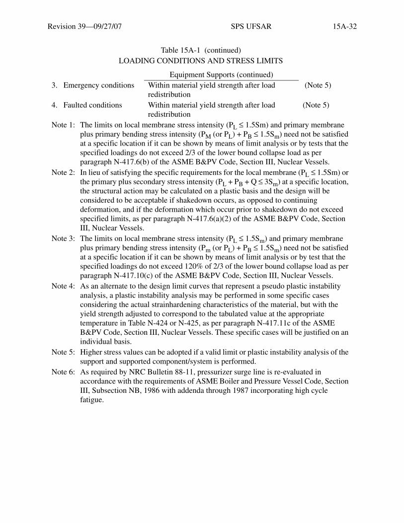
Revision 39—09/27/07 SPS UFSAR 15A-32
Equipment Supports (continued)3. Emergency conditions Within material yield strength after load
redistribution (Note 5)
4. Faulted conditions Within material yield strength after load redistribution
(Note 5)
Note 1: The limits on local membrane stress intensity (PL ≤ 1.5Sm) and primary membrane plus primary bending stress intensity (PM (or PL) + PB ≤ 1.5Sm) need not be satisfied at a specific location if it can be shown by means of limit analysis or by tests that the specified loadings do not exceed 2/3 of the lower bound collapse load as per paragraph N-417.6(b) of the ASME B&PV Code, Section III, Nuclear Vessels.
Note 2: In lieu of satisfying the specific requirements for the local membrane (PL ≤ 1.5Sm) or the primary plus secondary stress intensity (PL + PB + Q ≤ 3Sm) at a specific location, the structural action may be calculated on a plastic basis and the design will be considered to be acceptable if shakedown occurs, as opposed to continuing deformation, and if the deformation which occur prior to shakedown do not exceed specified limits, as per paragraph N-417.6(a)(2) of the ASME B&PV Code, Section III, Nuclear Vessels.
Note 3: The limits on local membrane stress intensity (PL ≤ 1.5Sm) and primary membrane plus primary bending stress intensity (Pm (or PL) + PB ≤ 1.5Sm) need not be satisfied at a specific location if it can be shown by means of limit analysis or by test that the specified loadings do not exceed 120% of 2/3 of the lower bound collapse load as per paragraph N-417.10(c) of the ASME B&PV Code, Section III, Nuclear Vessels.
Note 4: As an alternate to the design limit curves that represent a pseudo plastic instability analysis, a plastic instability analysis may be performed in some specific cases considering the actual strainhardening characteristics of the material, but with the yield strength adjusted to correspond to the tabulated value at the appropriate temperature in Table N-424 or N-425, as per paragraph N-417.11c of the ASME B&PV Code, Section III, Nuclear Vessels. These specific cases will be justified on an individual basis.
Note 5: Higher stress values can be adopted if a valid limit or plastic instability analysis of the support and supported component/system is performed.
Note 6: As required by NRC Bulletin 88-11, pressurizer surge line is re-evaluated in accordance with the requirements of ASME Boiler and Pressure Vessel Code, Section III, Subsection NB, 1986 with addenda through 1987 incorporating high cycle fatigue.
Table 15A-1 (continued) LOADING CONDITIONS AND STRESS LIMITS
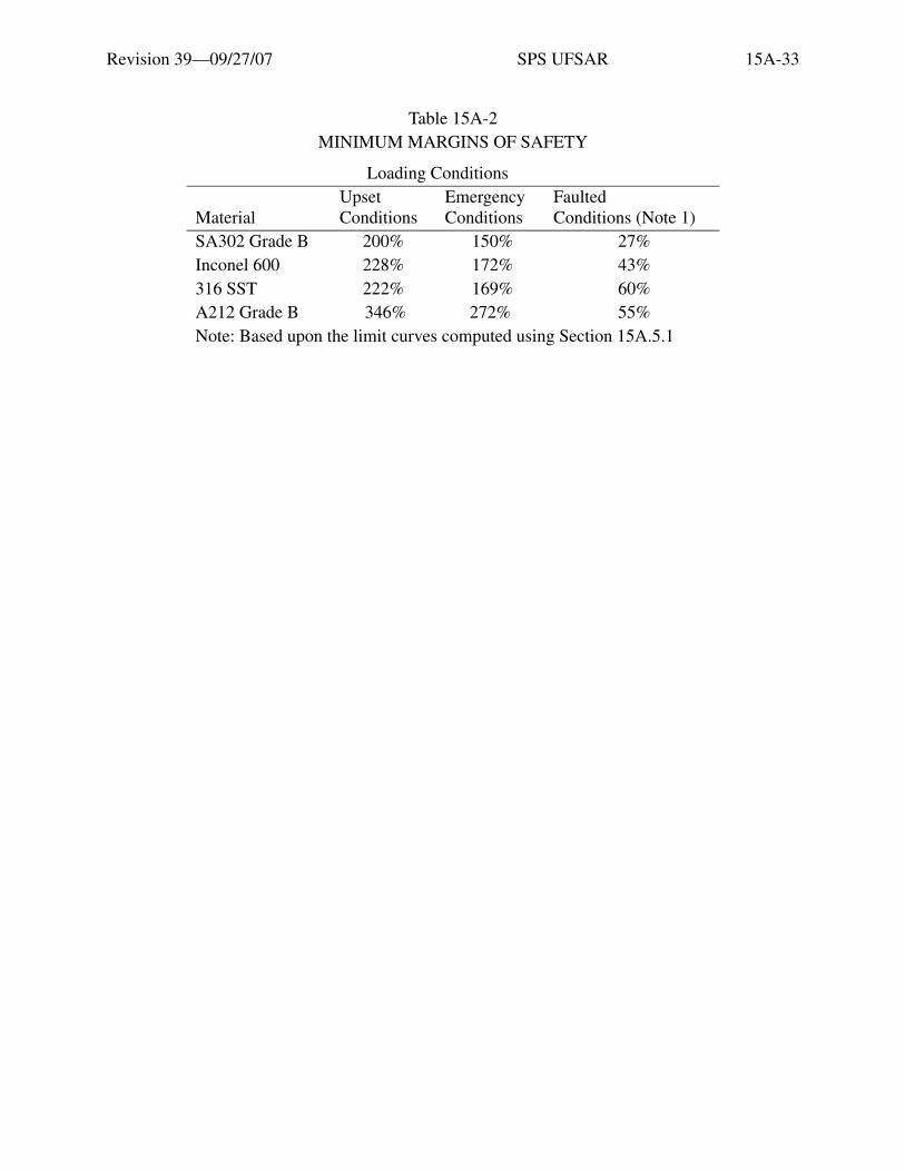
Revision 39—09/27/07 SPS UFSAR 15A-33
Table 15A-2MINIMUM MARGINS OF SAFETY
Loading Conditions
MaterialUpsetConditions
EmergencyConditions
FaultedConditions (Note 1)
SA302 Grade B 200% 150% 27%Inconel 600 228% 172% 43%316 SST 222% 169% 60%A212 Grade B 346% 272% 55%Note: Based upon the limit curves computed using Section 15A.5.1

Revision 39—09/27/07 SPS UFSAR 15A-34
Tabl
e 15
A-3
TEST
S A
ND
TE
ST R
ESU
LT
S O
N S
A 1
06B
CA
RB
ON
ST
EE
L P
IPE
SPE
CIM
EN
S(I
NT
ER
NA
L P
RE
SSU
RIZ
AT
ION
= 3
000
PSIA
)
Pseu
do-e
last
ic A
xial
Stre
ss N
orm
aliz
edto
the
Yie
ld S
tres
s
Pseu
do-e
last
icB
endi
ng S
tres
sN
orm
aliz
ed to
the
Yie
ld S
tres
s
Pseu
do-e
last
ic S
tres
sIn
tens
ityN
orm
aliz
ed to
the
Yie
ld S
tres
sSt
rain
Per
cent
(gau
ge le
ngth
)
Pure
tens
ion
(no
wel
d)1.
736
1.84
00.
00.
01.
770
1.84
722
.61%
(12
in.)
22.3
2% (
12 in
.)
Pure
ben
ding
a0.
10>
2.34
82.
382
>35
.4X
(1
in.)
Tens
ion
+ b
endi
ng (
no w
eld)
>
1.37
5>
1.58
5>
1.84
5
>1.
030
>0.
565
>0.
266
2.44
02.
180
2.14
5
>7.
75%
(6
in.)
-- --
Com
pres
sion
+ b
endi
ng (
no w
eld)
>1.
130
1.08
2.41
0--
Pure
tens
ion
(cir
cum
f. w
eld)
1.85
20.
0 1.
886
20.0
5% (
12 in
.)
Pure
ben
ding
(ci
rcum
f. w
eld)
0.10
>2.
580
2.61
4>
30.1
9X (
1.5
in.)
Pure
ben
ding
b
(rej
ecte
d ci
rcum
f. w
eld)
0.10
2.46
02.
494
14.5
1% (
2 in
.)
a.T
he li
mit
capa
bilit
y of
the
test
app
arat
us h
as b
een
reac
hed
befo
re f
ailu
re o
f th
ese
spec
imen
s w
as a
ppro
ache
d.
b.T
his
test
was
per
form
ed o
n a
wel
ded
pipe
spe
cim
en th
at h
as b
een
reje
cted
by
the
insp
ecto
r pr
ior
to th
e te
st f
or g
ross
lack
of
pene
trat
ion
in
wel
d. T
his
was
the
only
test
in w
hich
the
wel
d fa
iled
. The
spe
cim
en e
xhib
ited
subs
tant
ial d
ucti
lity
prio
r to
fai
lure
.
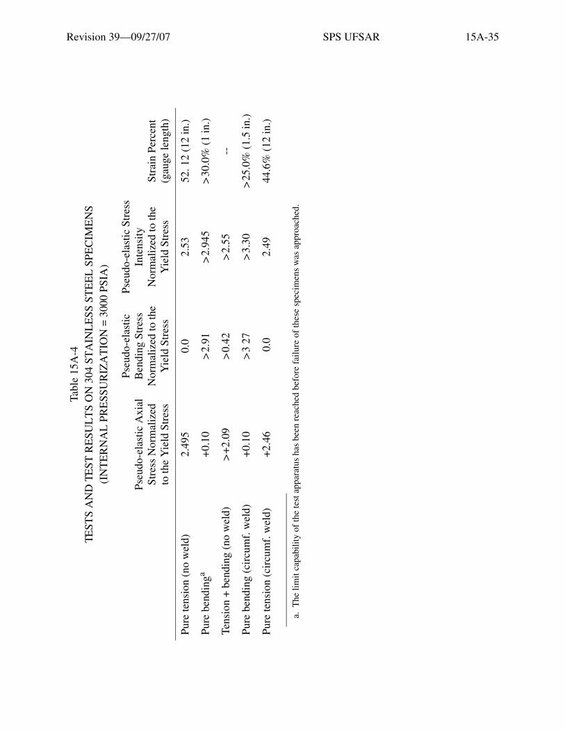
Revision 39—09/27/07 SPS UFSAR 15A-35
Tabl
e 15
A-4
TEST
S A
ND
TE
ST R
ESU
LT
S O
N 3
04 S
TA
INL
ESS
ST
EE
L S
PEC
IME
NS
(IN
TE
RN
AL
PR
ESS
UR
IZA
TIO
N =
300
0PS
IA)
Pseu
do-e
last
ic A
xial
Stre
ss N
orm
aliz
edto
the
Yie
ld S
tres
s
Pseu
do-e
last
icB
endi
ng S
tres
sN
orm
aliz
ed to
the
Yie
ld S
tres
s
Pseu
do-e
last
ic S
tres
sIn
tens
ityN
orm
aliz
ed to
the
Yie
ld S
tres
sSt
rain
Per
cent
(gau
ge le
ngth
)
Pure
tens
ion
(no
wel
d)2.
495
0.0
2.53
52. 1
2 (1
2 in
.)
Pure
ben
ding
a+
0.10
>2.
91>
2.94
5>
30.0
% (
1 in
.)
Tens
ion
+ b
endi
ng (
no w
eld)
>+
2.09
>0.
42>
2.55
--
Pure
ben
ding
(ci
rcum
f. w
eld)
+0.
10>
3 27
>3.
30>
25.0
% (
1.5
in.)
Pure
tens
ion
(cir
cum
f. w
eld)
+2.
46 0
.0
2.49
44.6
% (
12 in
.)
a.T
he li
mit
capa
bilit
y of
the
test
app
arat
us h
as b
een
reac
hed
befo
re f
ailu
re o
f th
ese
spec
imen
s w
as a
ppro
ache
d.

Revision 39—09/27/07 SPS UFSAR 15A-36
Table 15A-5LEVEL OF STRESS AS A PERCENTAGE OF CODE ALLOWABLE STRESS
Loading Hot Leg Crossover Leg Cold Leg Code Allowable StressThermal 38.6% 15.6% 7.4% SAPressure + Deadweight 68.0% 48.7% 53.3% 1. 0Sh
a
Pressure + Deadweight + OBE
65.5% 65.0* 60. 0% 1. 2Sha
Pressure + Deadweight + DBE
49.6% 51.1% 48.9% 1. 8Sha
In addition, the pipe Stresses in the primary reactor coolant loop piping under combined accident loadings from pressure, deadweight, plus SRSS of design-basis earthquake and controlling pipe ruptures are less than 1.8Sh, which is conservative both respect to the allowables per Section 15A.5 and to 2. 4Sh which is permitted by the current ASME Code.
a. Sh =15 Ksi

Revision 39—09/27/07 SPS UFSAR 15A-37
Table 15A-6FACTORS OF SAFETY FOR COMPONENT SUPPORTS UNDER DESIGN-BASIS SEISMIC
AND NORMAL OPERATING LOADS SURRY UNITS 1 AND 2
Component Factor of Safetya
OriginalDesignb
ModifiedDesignc Final Designd
Steam Generator Shell >20.0 >20.0 >20.0Steam Generator Upper Support
Component 19.2 15.9 13.7Upper Guide 7.3 4.6 3.3Snubber 14.2 14.2 6.3
Steam Generator Lower SupportHanger Rod 1.8 1.8 1.8Swivel End Coupling 16.3 13.4 12.2
Steam Generator FootVertical Force 2.7 2.8 2.8Tangential Force 16.0 12.4 12.4
Reactor Coolant Pump FootVertical Force 5.5 5.2 5.3Tangential Force 15.4 15.8 15.9Radial Force 15.4 15.0 12.8
Reactor Coolant Pump SupportUpper Vertical 5.5 5.0 5.0Upper Horizontal 5.0 5.0 5.0 Lower Vertical 3.6 3.6 3.6Lower Diagonal 4.6 4.6 4.6
a. Factor of Safety - (Allowable Load)/(TotaL Load of Deadweight, Pressure, Thermal and DBE)
b. Original design incorporated ten large-bore snubber per loop for primary reactor coolant system pipe rupture loads.
c. Modified design implemented elimination of six large-bore snubbers based on “leak-before-break”; n the four remaining large-bore snubbers were required to carry loads of main steam line rupture.
d. Final design incorporates only two large-bore snubbers on Steam Generator, following elimination of lateral loads due to postulated AIB of Main Steam Line.

Revision 39—09/27/07 SPS UFSAR 15A-38
Table 15A-7FACTORS OF SAFETY FOR COMPONENT SUPPORTS UNDER COMBINED
ACCIDENT LOADS SURRY UNITS 1 AND 2
Component Factor of Safetya
OriginalDesignc
ModifiedDesignd Final Designe
Steam Generator Shell 2.5 2.4 8.3Steam Generator Upper Support
Component 2.8 2.8 7.5Upper Guide 1.1 1.1 2.6Snubber 1.3 1.4 1.9
Steam Generator Lower SupportHanger Rod 1.7 1.7 1.7Swivel End Coupling 2.3 2.3 2.3
Steam Generator Footb
Vertical Force 4.0 4.2 4.3Tangential Force 7.4 7.2 7.3
Reactor Coolant Pump Footb
Vertical Force 11.9 11.3 10.9Tangential Force >20.0 >20.0 >20.0Radial Force >20.0 >20.0 >20.0
Reactor Coolant Pump SupportUpper Vertical 4.5 4.3 4.2Upper Horizontal 5.3 4.8 4.6Lower Vertical 3.8 3.5 3.5Lower Diagonal 3.0 3.0 3.0
a. Factor of Safety - (Allowable Load)/[TotaL Load of Deadweight, Pressure, Thermal and SRSS (DBE+Pipe Rupture)].
b. Allowable loads from Westinghouse specification are higher for pipe rupture case; this results in higher normal factors of safety for some components for this case compared with factors of safety for design basis seismic loads only (Table 15A-4).
c. Original design incorporated ten large-bore snubber per loop for primary reactor coolant system pipe rupture loads.
d. Modified design implemented elimination of six large-bore snubbers based on “leak-before-break”; n the four remaining large-bore snubbers were required to carry loads of main steam line rupture.
e. Final design incorporates only two large-bore snubbers on Steam Generator, following elimination of lateral loads due to postulated AIB of Main Steam Line.
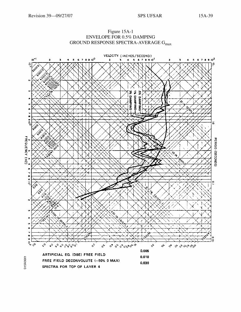
Revision 39—09/27/07 SPS UFSAR 15A-39
Figure 15A-1 ENVELOPE FOR 0.5% DAMPING
GROUND RESPONSE SPECTRA-AVERAGE Gmax

Revision 39—09/27/07 SPS UFSAR 15A-40
Figure 15A-2 ENVELOPE FOR 0.5% DAMPING
GROUND RESPONSE SPECTRA-AVERAGE Gmax + 50%
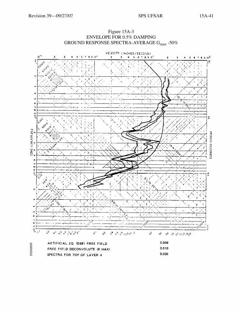
Revision 39—09/27/07 SPS UFSAR 15A-41
Figure 15A-3 ENVELOPE FOR 0.5% DAMPING
GROUND RESPONSE SPECTRA-AVERAGE Gmax -50%

Revision 39—09/27/07 SPS UFSAR 15A-42
Figu
re 1
5A-4
D
ESI
GN
LIM
ITS
CO
MPA
RE
D T
O E
XPE
RIM
EN
TA
L P
OIN
TS,
SA
106
B C
AR
BO
N S
TE
EL
Etia
m v
enen
atis
acc
umsa
n en
im. M
auris
rut
rum
, dia
m q
uis
tinci
dunt
ele
men
tum
, sem
orc
i bib
endu
m li
bero
, ut e
lem
entu
m
just
o m
agna
at a
ugue
. Aliq
uam
sap
ien
mas
sa, f
auci
bus
ac, e
lem
entu
m n
on, l
aore
et n
ec, f
elis
. Ves
tibul
um a
ccum
san
sagi
ttis
ipsu
m. I
n ul
lam
corp
er, d
ui s
ed c
ursu
s eu
ism
od, a
nte
wis
i dap
ibus
ligu
la, i
d rh
oncu
s ip
sum
mi a
t tel
lus.
Cla
ss a
pten
t ta
citi
soci
osqu
ad
litor
a to
rque
nt p
er c
onub
ia n
ostr
a, p
er in
cept
os h
ymen
aeos
. Qui
sque
rho
ncus
wis
i vita
e do
lor.
Etia
m
elei
fend
. Int
eger
impe
rdie
t veh
icul
a an
te. S
ed in
arc
u et
odi
o ac
cum
san
port
a. A
enea
n m
i. V
ivam
us n
on o
rci v
itae
urna
al
ique
t ulla
mco
rper
. Cla
ss a
pten
t tac
iti s
ocio
squ
ad li
tora
torq
uent
per
con
ubia
nos
tra,
per
ince
ptos
hym
enae
os. I
n fr
ingi
lla
ligul
a ve
l odi
o. In
hac
hab
itass
e pl
atea
dic
tum
st. E
tiam
tem
pus
lacu
s ac
arc
u. P
raes
ent n
on li
bero
.
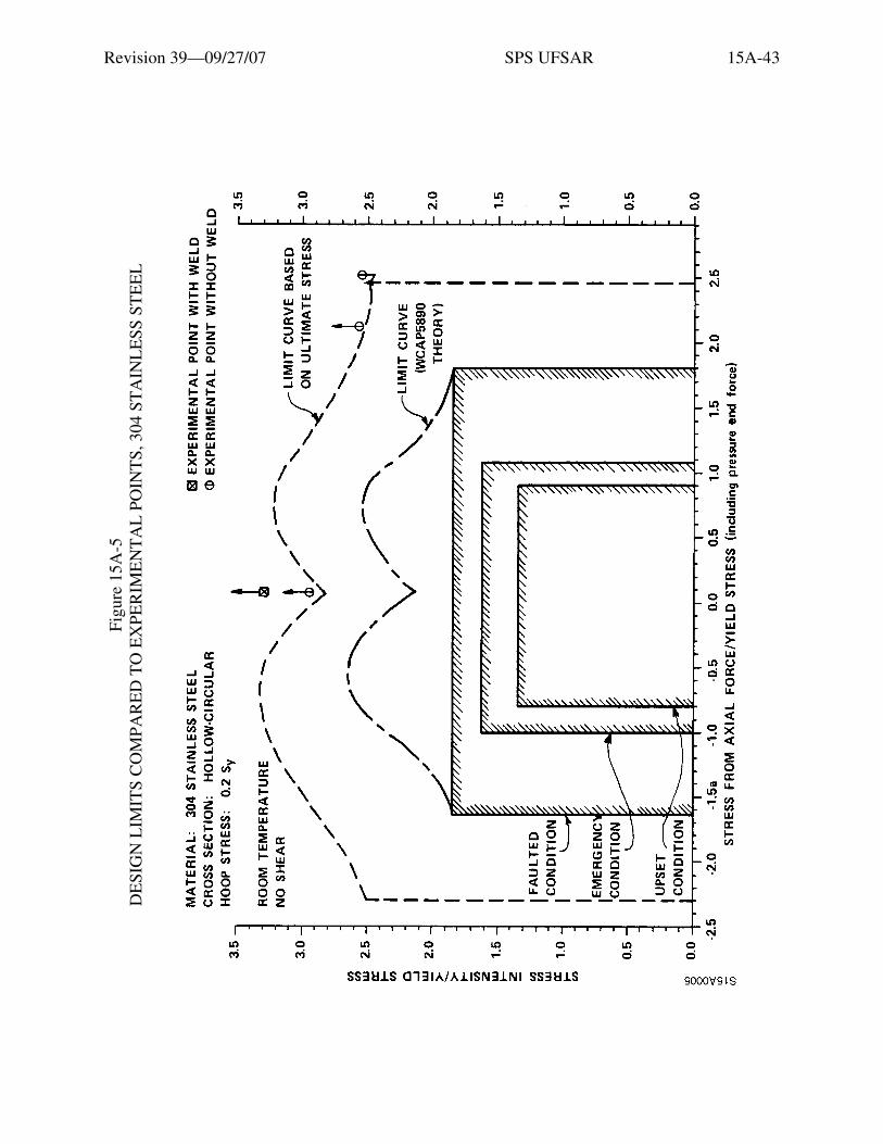
Revision 39—09/27/07 SPS UFSAR 15A-43
Figu
re 1
5A-5
D
ESI
GN
LIM
ITS
CO
MPA
RE
D T
O E
XPE
RIM
EN
TA
L P
OIN
TS,
304
ST
AIN
LE
SS S
TE
EL
Etia
m v
enen
atis
acc
umsa
n en
im. M
auris
rut
rum
, dia
m q
uis
tinci
dunt
ele
men
tum
, sem
orc
i bib
endu
m li
bero
, ut e
lem
entu
m
just
o m
agna
at a
ugue
. Aliq
uam
sap
ien
mas
sa, f
auci
bus
ac, e
lem
entu
m n
on, l
aore
et n
ec, f
elis
. Ves
tibul
um a
ccum
san
sagi
ttis
ipsu
m. I
n ul
lam
corp
er, d
ui s
ed c
ursu
s eu
ism
od, a
nte
wis
i dap
ibus
ligu
la, i
d rh
oncu
s ip
sum
mi a
t tel
lus.
Cla
ss a
pten
t ta
citi
soci
osqu
ad
litor
a to
rque
nt p
er c
onub
ia n
ostr
a, p
er in
cept
os h
ymen
aeos
. Qui
sque
rho
ncus
wis
i vita
e do
lor.
Etia
m
elei
fend
. Int
eger
impe
rdie
t veh
icul
a an
te. S
ed in
arc
u et
odi
o ac
cum
san
port
a. A
enea
n m
i. V
ivam
us n
on o
rci v
itae
urna
al
ique
t ulla
mco
rper
. Cla
ss a
pten
t tac
iti s
ocio
squ
ad li
tora
torq
uent
per
con
ubia
nos
tra,
per
ince
ptos
hym
enae
os. I
n fr
ingi
lla
ligul
a ve
l odi
o. In
hac
hab
itass
e pl
atea
dic
tum
st. E
tiam
tem
pus
lacu
s ac
arc
u. P
raes
ent n
on li
bero
.
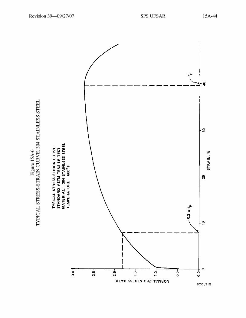
Revision 39—09/27/07 SPS UFSAR 15A-44
Figu
re 1
5A-6
TY
PIC
AL
ST
RE
SS-S
TR
AIN
CU
RV
E, 3
04 S
TA
INL
ESS
ST
EE
L
Etia
m v
enen
atis
acc
umsa
n en
im. M
auris
rut
rum
, dia
m q
uis
tinci
dunt
ele
men
tum
, sem
orc
i bib
endu
m li
bero
, ut e
lem
entu
m
just
o m
agna
at a
ugue
. Aliq
uam
sap
ien
mas
sa, f
auci
bus
ac, e
lem
entu
m n
on, l
aore
et n
ec, f
elis
. Ves
tibul
um a
ccum
san
sagi
ttis
ipsu
m. I
n ul
lam
corp
er, d
ui s
ed c
ursu
s eu
ism
od, a
nte
wis
i dap
ibus
ligu
la, i
d rh
oncu
s ip
sum
mi a
t tel
lus.
Cla
ss a
pten
t ta
citi
soci
osqu
ad
litor
a to
rque
nt p
er c
onub
ia n
ostr
a, p
er in
cept
os h
ymen
aeos
. Qui
sque
rho
ncus
wis
i vita
e do
lor.
Etia
m
elei
fend
. Int
eger
impe
rdie
t veh
icul
a an
te. S
ed in
arc
u et
odi
o ac
cum
san
port
a. A
enea
n m
i. V
ivam
us n
on o
rci v
itae
urna
al
ique
t ulla
mco
rper
. Cla
ss a
pten
t tac
iti s
ocio
squ
ad li
tora
torq
uent
per
con
ubia
nos
tra,
per
ince
ptos
hym
enae
os. I
n fr
ingi
lla
ligul
a ve
l odi
o. In
hac
hab
itass
e pl
atea
dic
tum
st. E
tiam
tem
pus
lacu
s ac
arc
u. P
raes
ent n
on li
bero
.

Revision 39—09/27/07 SPS UFSAR 15A-45
Figure 15A-7 TYPICAL STRESS-STRAIN CURVE, INCONEL 600

Revision 39—09/27/07 SPS UFSAR 15A-46
Figu
re 1
5A-8
TY
PIC
AL
ST
RE
SS-S
TR
AIN
CU
RV
E, S
A 3
02 G
RA
DE
B
Etia
m v
enen
atis
acc
umsa
n en
im. M
auris
rut
rum
, dia
m q
uis
tinci
dunt
ele
men
tum
, sem
orc
i bib
endu
m li
bero
, ut e
lem
entu
m
just
o m
agna
at a
ugue
. Aliq
uam
sap
ien
mas
sa, f
auci
bus
ac, e
lem
entu
m n
on, l
aore
et n
ec, f
elis
. Ves
tibul
um a
ccum
san
sagi
ttis
ipsu
m. I
n ul
lam
corp
er, d
ui s
ed c
ursu
s eu
ism
od, a
nte
wis
i dap
ibus
ligu
la, i
d rh
oncu
s ip
sum
mi a
t tel
lus.
Cla
ss a
pten
t ta
citi
soci
osqu
ad
litor
a to
rque
nt p
er c
onub
ia n
ostr
a, p
er in
cept
os h
ymen
aeos
. Qui
sque
rho
ncus
wis
i vita
e do
lor.
Etia
m
elei
fend
. Int
eger
impe
rdie
t veh
icul
a an
te. S
ed in
arc
u et
odi
o ac
cum
san
port
a. A
enea
n m
i. V
ivam
us n
on o
rci v
itae
urna
al
ique
t ulla
mco
rper
. Cla
ss a
pten
t tac
iti s
ocio
squ
ad li
tora
torq
uent
per
con
ubia
nos
tra,
per
ince
ptos
hym
enae
os. I
n fr
ingi
lla
ligul
a ve
l odi
o. In
hac
hab
itass
e pl
atea
dic
tum
st. E
tiam
tem
pus
lacu
s ac
arc
u. P
raes
ent n
on li
bero
.