CHAPTER 13 Power-Assisted Steering Operation and Service.
83
CHAPTER 13 Power-Assisted Steering Operation and Service
Transcript of CHAPTER 13 Power-Assisted Steering Operation and Service.

CHAPTER 13
Power-Assisted Steering Operation and Service

Automotive Steering, Suspension and Alignment, 5/eBy James D. Halderman
Copyright © 2010, 2008, 2004, 2000, 1995 Pearson Education, Inc.,Upper Saddle River, NJ 07458 • All rights reserved.2
After studying Chapter 13, the reader will be able to:
1. Prepare for ASE Suspension and Steering (A4) certification test content area “A” (Steering Systems Diagnosis and Repairs).
2. Discuss the components and operation of power steering pumps.
3. List the components of a typical power-recirculating-ball-nut steering gear system.
4. Describe the operation of a power rack-and-pinion steering system.
OBJECTIVES

Automotive Steering, Suspension and Alignment, 5/eBy James D. Halderman
Copyright © 2010, 2008, 2004, 2000, 1995 Pearson Education, Inc.,Upper Saddle River, NJ 07458 • All rights reserved.3
KEY TERMS
• BPP • EHPS • EPS • EVO • Flow control valve • Force • Integral reservoir • Magnasteer • Pascal’s law • Poppet valve • Pressure
• Pressure-relief valve • PSCM • PSP • Remote reservoir • Rotary control valve • Self-park • SPS • SSS • TFE • VES

Automotive Steering, Suspension and Alignment, 5/eBy James D. Halderman
Copyright © 2010, 2008, 2004, 2000, 1995 Pearson Education, Inc.,Upper Saddle River, NJ 07458 • All rights reserved.4
POWER STEERING HYDRAULIC SYSTEMS
• Hydraulics is the study of liquids and their use to transmit force and motion.
• Hydraulic systems transmit force and motion through the use of fluid pressure. • Force is a push or pull acting on an object and is
usually measured in pounds or Newtons.• Pressure is force applied to a specific area.
• Pressure is usually measured in force per unit of area, such as pounds per square inch (PSI), or kilopascals (kPa). One PSI is equal to 6.895 kPa.

Automotive Steering, Suspension and Alignment, 5/eBy James D. Halderman
Copyright © 2010, 2008, 2004, 2000, 1995 Pearson Education, Inc.,Upper Saddle River, NJ 07458 • All rights reserved.5
POWER STEERING HYDRAULIC SYSTEMS
FIGURE 13–1 Hydraulic fluid transmits the same force whether it passes through a single chamber or two chambers connected by a narrow passage.

Automotive Steering, Suspension and Alignment, 5/eBy James D. Halderman
Copyright © 2010, 2008, 2004, 2000, 1995 Pearson Education, Inc.,Upper Saddle River, NJ 07458 • All rights reserved.6
POWER STEERING HYDRAULIC SYSTEMS
FIGURE 13–2 A fluid applies a force equal to the applied force on a surface that is equal in size to the applying surface. If the surface is half the size, then the fluid exerts half the force: if the surface is twice as large, the fluid exerts twice the force.

Automotive Steering, Suspension and Alignment, 5/eBy James D. Halderman
Copyright © 2010, 2008, 2004, 2000, 1995 Pearson Education, Inc.,Upper Saddle River, NJ 07458 • All rights reserved.7
POWER STEERING PUMP AND RESERVOIR
• The power steering pump draws fluid from the reservoir, pressurizes it, and delivers it to the power steering system.
• A power steering pump produces a high-pressure stream of fluid, typically in the 1,500-PSI (10,500 kPa) range.
• The fluid reservoir may be either integral to (built into) the pump or remotely mounted and connected to the pump by a hose.
• The power steering fluid reservoir is usually made of either plastic or stamped metal, and it includes the fluid filler neck, cap, and dipstick.
• It can be integral to or remote from the pump. • An integral reservoir is part of the pump, and the pump
itself operates submerged in power steering fluid.

Automotive Steering, Suspension and Alignment, 5/eBy James D. Halderman
Copyright © 2010, 2008, 2004, 2000, 1995 Pearson Education, Inc.,Upper Saddle River, NJ 07458 • All rights reserved.8
POWER STEERING PUMP AND RESERVOIR
FIGURE 13–3 A typical integral power steering pump when the pump is mounted inside the reservoir.

Automotive Steering, Suspension and Alignment, 5/eBy James D. Halderman
Copyright © 2010, 2008, 2004, 2000, 1995 Pearson Education, Inc.,Upper Saddle River, NJ 07458 • All rights reserved.9
POWER STEERING PUMP AND RESERVOIR
FIGURE 13–4 Typical remote reservoir.
Automotive Steering, Suspension and Alignment, 5/eBy James D. Halderman
Copyright © 2010, 2008, 2004, 2000, 1995 Pearson Education, Inc.,Upper Saddle River, NJ 07458 • All rights reserved.10
POWER STEERING PUMP AND RESERVOIR
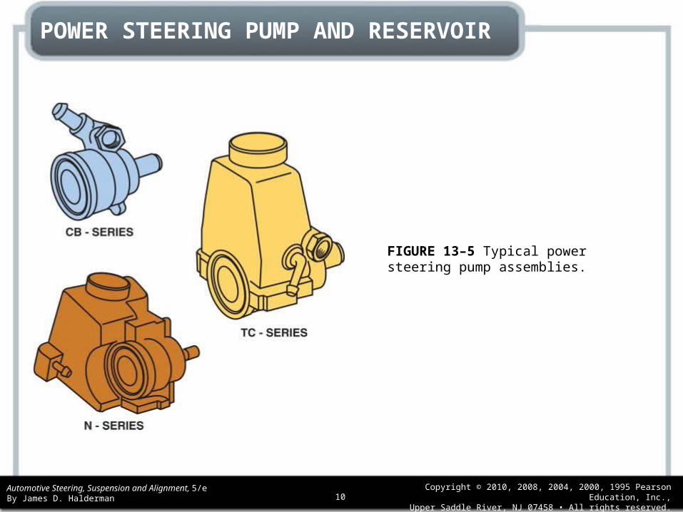
FIGURE 13–5 Typical power steering pump assemblies.

Automotive Steering, Suspension and Alignment, 5/eBy James D. Halderman
Copyright © 2010, 2008, 2004, 2000, 1995 Pearson Education, Inc.,Upper Saddle River, NJ 07458 • All rights reserved.11
POWER STEERING PUMP AND RESERVOIR
FIGURE 13–6 General Motors vane-type pump.

Automotive Steering, Suspension and Alignment, 5/eBy James D. Halderman
Copyright © 2010, 2008, 2004, 2000, 1995 Pearson Education, Inc.,Upper Saddle River, NJ 07458 • All rights reserved.12
POWER STEERING PUMP AND RESERVOIR
FIGURE 13–7 Vane pump operation. In phase 1, the rotor moves past the opposed suction ports, and the vanes move out to maintain contact with the ring. This creates a low-pressure area, drawing fluid into the cavities formed by the vanes. As the rotor continues to move during phase 2, the vanes follow the contour of the ring. The contour of the ring forms a larger cavity between the vanes. This increases the suction and draws more fluid into the pump.

Automotive Steering, Suspension and Alignment, 5/eBy James D. Halderman
Copyright © 2010, 2008, 2004, 2000, 1995 Pearson Education, Inc.,Upper Saddle River, NJ 07458 • All rights reserved.13
POWER STEERING PUMP AND RESERVOIR
FIGURE 13–8 Vane pump operation—continued. At phase 3, the vanes are at the end of the intake port of the pump and the cavity has reached its maximum volume. In phase 4, the rotor moves into alignment with the opposed discharge ports.
Automotive Steering, Suspension and Alignment, 5/eBy James D. Halderman
Copyright © 2010, 2008, 2004, 2000, 1995 Pearson Education, Inc.,Upper Saddle River, NJ 07458 • All rights reserved.14
POWER STEERING PUMP AND RESERVOIR
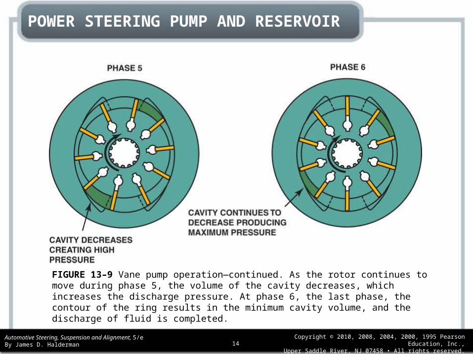
FIGURE 13–9 Vane pump operation—continued. As the rotor continues to move during phase 5, the volume of the cavity decreases, which increases the discharge pressure. At phase 6, the last phase, the contour of the ring results in the minimum cavity volume, and the discharge of fluid is completed.

Automotive Steering, Suspension and Alignment, 5/eBy James D. Halderman
Copyright © 2010, 2008, 2004, 2000, 1995 Pearson Education, Inc.,Upper Saddle River, NJ 07458 • All rights reserved.15
POWER STEERING PUMP AND RESERVOIR
FIGURE 13–10 Flow control valve.

Automotive Steering, Suspension and Alignment, 5/eBy James D. Halderman
Copyright © 2010, 2008, 2004, 2000, 1995 Pearson Education, Inc.,Upper Saddle River, NJ 07458 • All rights reserved.16
POWER STEERING PUMP AND RESERVOIR
FIGURE 13–11 The pressure-relief check ball unseats, allowing fluid to flow back into the pump inlet if the pressure rises above a certain limit.
Automotive Steering, Suspension and Alignment, 5/eBy James D. Halderman
Copyright © 2010, 2008, 2004, 2000, 1995 Pearson Education, Inc.,Upper Saddle River, NJ 07458 • All rights reserved.17
POWER STEERING HOSES
• Because the power steering pump and the steering gear are not part of the same assembly, the system requires two hoses to connect the power steering pump and gear assembly.
• The pressure hose is connected to the flow control/relief valve.
• This hose supplies pressurized fluid to the steering gear. • The second hose is called the return hose and it returns the
fluid from the steering gear back to the pump. • Some vehicles will use a cooler in the return path to the
pump. • The cooler is used to reduce the temperature of the fluid
before it enters the pump.

Automotive Steering, Suspension and Alignment, 5/eBy James D. Halderman
Copyright © 2010, 2008, 2004, 2000, 1995 Pearson Education, Inc.,Upper Saddle River, NJ 07458 • All rights reserved.18
POWER STEERING HOSES
FIGURE 13–12 The power steering fluid cooler, if used, is located in the return hose. Often the “cooler” is simply a length of return metal line that is arranged in a loop and routed near the front of the vehicle. The airflow past the return line helps reduce the temperature of the fluid.

Automotive Steering, Suspension and Alignment, 5/eBy James D. Halderman
Copyright © 2010, 2008, 2004, 2000, 1995 Pearson Education, Inc.,Upper Saddle River, NJ 07458 • All rights reserved.19
INTEGRAL POWER STEERING
• In an integral power steering system, the control valve and the power piston are incorporated into the steering gear construction.
• The control valve regulates the application of pressurized fluid against the power piston, and the power piston helps move the output member of the steering gear when pressure is applied to one side of it.

Automotive Steering, Suspension and Alignment, 5/eBy James D. Halderman
Copyright © 2010, 2008, 2004, 2000, 1995 Pearson Education, Inc.,Upper Saddle River, NJ 07458 • All rights reserved.20
INTEGRAL POWER STEERING
• INTEGRAL STANDARD STEERING GEAR• ROTARY CONTROL VALVE• POWER RACK-AND-PINION STEERING• FLOW CONTROL VALVE OPERATION

Automotive Steering, Suspension and Alignment, 5/eBy James D. Halderman
Copyright © 2010, 2008, 2004, 2000, 1995 Pearson Education, Inc.,Upper Saddle River, NJ 07458 • All rights reserved.21
INTEGRAL POWER STEERING
FIGURE 13–13 Forces acting on the rack piston of an integral power steering gear.

Automotive Steering, Suspension and Alignment, 5/eBy James D. Halderman
Copyright © 2010, 2008, 2004, 2000, 1995 Pearson Education, Inc.,Upper Saddle River, NJ 07458 • All rights reserved.22
INTEGRAL POWER STEERING
FIGURE 13–14 The rotary valve consists of inner and outer elements. The worm gear is part of the outer element and the torsion bar is part of the inner element. A pin attaches the worm gear to the bottom of the torsion bar to join the two elements together.

Automotive Steering, Suspension and Alignment, 5/eBy James D. Halderman
Copyright © 2010, 2008, 2004, 2000, 1995 Pearson Education, Inc.,Upper Saddle River, NJ 07458 • All rights reserved.23
INTEGRAL POWER STEERING
FIGURE 13–15 When the steering wheel is in the straight-ahead position, all of the ports in a rotary valve are open equally to the pressure and return circuits.

Automotive Steering, Suspension and Alignment, 5/eBy James D. Halderman
Copyright © 2010, 2008, 2004, 2000, 1995 Pearson Education, Inc.,Upper Saddle River, NJ 07458 • All rights reserved.24
INTEGRAL POWER STEERING
FIGURE 13–16 During a left turn, the inner element turns so that the left-turn circuits are open to pressure and the right-turn circuits are open to the return circuit.

Automotive Steering, Suspension and Alignment, 5/eBy James D. Halderman
Copyright © 2010, 2008, 2004, 2000, 1995 Pearson Education, Inc.,Upper Saddle River, NJ 07458 • All rights reserved.25
INTEGRAL POWER STEERING
FIGURE 13–17 During a left turn, the high-pressure fluid helps push the piston along the worm gear, thereby reducing the steering effort from the driver.

Automotive Steering, Suspension and Alignment, 5/eBy James D. Halderman
Copyright © 2010, 2008, 2004, 2000, 1995 Pearson Education, Inc.,Upper Saddle River, NJ 07458 • All rights reserved.26
INTEGRAL POWER STEERING
FIGURE 13–18 During a right turn, the inner element turns so that the right-turn outlets are open to pressure and the left-turn outlets are open to the return circuit.

Automotive Steering, Suspension and Alignment, 5/eBy James D. Halderman
Copyright © 2010, 2008, 2004, 2000, 1995 Pearson Education, Inc.,Upper Saddle River, NJ 07458 • All rights reserved.27
INTEGRAL POWER STEERING
FIGURE 13–19 During a right turn, high-pressure fluid pushes the piston up the worm gear, moving the sector shaft and pitman arm to provide assist during a right turn.

Automotive Steering, Suspension and Alignment, 5/eBy James D. Halderman
Copyright © 2010, 2008, 2004, 2000, 1995 Pearson Education, Inc.,Upper Saddle River, NJ 07458 • All rights reserved.28
INTEGRAL POWER STEERING
FIGURE 13–20 During a left turn, the control valve directs pressure into the left-turn fluid line and the rack moves left. (See inset.) Fluid pushed out of the right-turn fluid chamber travels back through the right-turn fluid line and control valve to the return circuit.

Automotive Steering, Suspension and Alignment, 5/eBy James D. Halderman
Copyright © 2010, 2008, 2004, 2000, 1995 Pearson Education, Inc.,Upper Saddle River, NJ 07458 • All rights reserved.29
INTEGRAL POWER STEERING
FIGURE 13–21 The control valve routes high-pressure fluid to the left-hand side of the power piston, which pushes the piston and assists in moving the rack toward the right when the steering wheel is turned right.

Automotive Steering, Suspension and Alignment, 5/eBy James D. Halderman
Copyright © 2010, 2008, 2004, 2000, 1995 Pearson Education, Inc.,Upper Saddle River, NJ 07458 • All rights reserved.30
INTEGRAL POWER STEERING
FIGURE 13–22 Low-speed flow control.

Automotive Steering, Suspension and Alignment, 5/eBy James D. Halderman
Copyright © 2010, 2008, 2004, 2000, 1995 Pearson Education, Inc.,Upper Saddle River, NJ 07458 • All rights reserved.31
INTEGRAL POWER STEERING
FIGURE 13–23 High-speed flow control operation.

Automotive Steering, Suspension and Alignment, 5/eBy James D. Halderman
Copyright © 2010, 2008, 2004, 2000, 1995 Pearson Education, Inc.,Upper Saddle River, NJ 07458 • All rights reserved.32
INTEGRAL POWER STEERING
FIGURE 13–24 Pressure-relief mode. In this mode the steering gear has blocked the flow of fluid from the pump and the pressure rises, which unseats the pressure-relief valve. Now fluid flows back to the inlet through the pressure-relief orifice and passage.

Automotive Steering, Suspension and Alignment, 5/eBy James D. Halderman
Copyright © 2010, 2008, 2004, 2000, 1995 Pearson Education, Inc.,Upper Saddle River, NJ 07458 • All rights reserved.33
VARIABLE-EFFORT STEERING
• Variable-effort steering (VES) systems are designed to provide variable power-assisted steering.
• The amount of power assist increases at lower vehicle speeds to aid parking maneuvers and decreases at higher speeds for greater road feel.
• As examples, General Motors uses four different variableeffort steering systems:• Electronic Variable Orifice (EVO)• Two-Flow Electronic (TFE)• Speed Sensitive Steering (SSS)• Magnasteer

Automotive Steering, Suspension and Alignment, 5/eBy James D. Halderman
Copyright © 2010, 2008, 2004, 2000, 1995 Pearson Education, Inc.,Upper Saddle River, NJ 07458 • All rights reserved.34
VARIABLE-EFFORT STEERING
FIGURE 13–25 EVO actuator assembly.

Automotive Steering, Suspension and Alignment, 5/eBy James D. Halderman
Copyright © 2010, 2008, 2004, 2000, 1995 Pearson Education, Inc.,Upper Saddle River, NJ 07458 • All rights reserved.35
VARIABLE-EFFORT STEERING
• ELECTRONIC VARIABLE ORIFICE (EVO) SYSTEM COMPONENTS
• TWO-FLOW ELECTRONIC (TFE) SYSTEM• SSS SYSTEM• MAGNASTEER

Automotive Steering, Suspension and Alignment, 5/eBy James D. Halderman
Copyright © 2010, 2008, 2004, 2000, 1995 Pearson Education, Inc.,Upper Saddle River, NJ 07458 • All rights reserved.36
VARIABLE-EFFORT STEERING
FIGURE 13–26 Integrated with the pinion shaft is a spool valve that senses the level of torque in the shaft and applies hydraulic pressure to the steering rack whenever assistance is needed. The electromagnet acts in parallel with the input shaft from the steering wheel to open or close the spool valve. The electromagnet generates variable torque, which can either increase or decrease the amount of steering torque that is needed to open the spool valve.

Automotive Steering, Suspension and Alignment, 5/eBy James D. Halderman
Copyright © 2010, 2008, 2004, 2000, 1995 Pearson Education, Inc.,Upper Saddle River, NJ 07458 • All rights reserved.37
VARIABLE-EFFORT STEERING
FIGURE 13–27 Magnasteer system.

Automotive Steering, Suspension and Alignment, 5/eBy James D. Halderman
Copyright © 2010, 2008, 2004, 2000, 1995 Pearson Education, Inc.,Upper Saddle River, NJ 07458 • All rights reserved.38
ELECTRIC POWER STEERING SYSTEM
• Most electric power steering units use a DC electric motor.
• Some operate from 42 volts while others operate from 12 volts.
• The electric power steering (EPS) is also called electric power-assisted steering (EPAS).
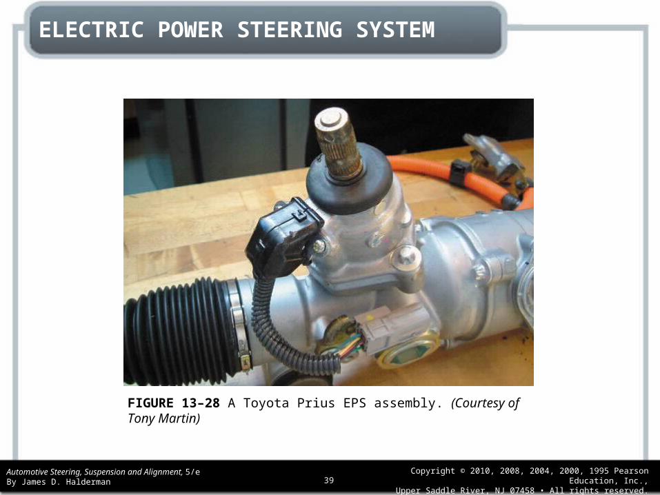
• The Toyota system on a Prius uses a DC motor, reduction gear, and torque sensor all mounted to the steering column.
Automotive Steering, Suspension and Alignment, 5/eBy James D. Halderman
Copyright © 2010, 2008, 2004, 2000, 1995 Pearson Education, Inc.,Upper Saddle River, NJ 07458 • All rights reserved.39
ELECTRIC POWER STEERING SYSTEM
FIGURE 13–28 A Toyota Prius EPS assembly. (Courtesy of Tony Martin)
Automotive Steering, Suspension and Alignment, 5/eBy James D. Halderman
Copyright © 2010, 2008, 2004, 2000, 1995 Pearson Education, Inc.,Upper Saddle River, NJ 07458 • All rights reserved.40
ELECTRIC POWER STEERING SYSTEM
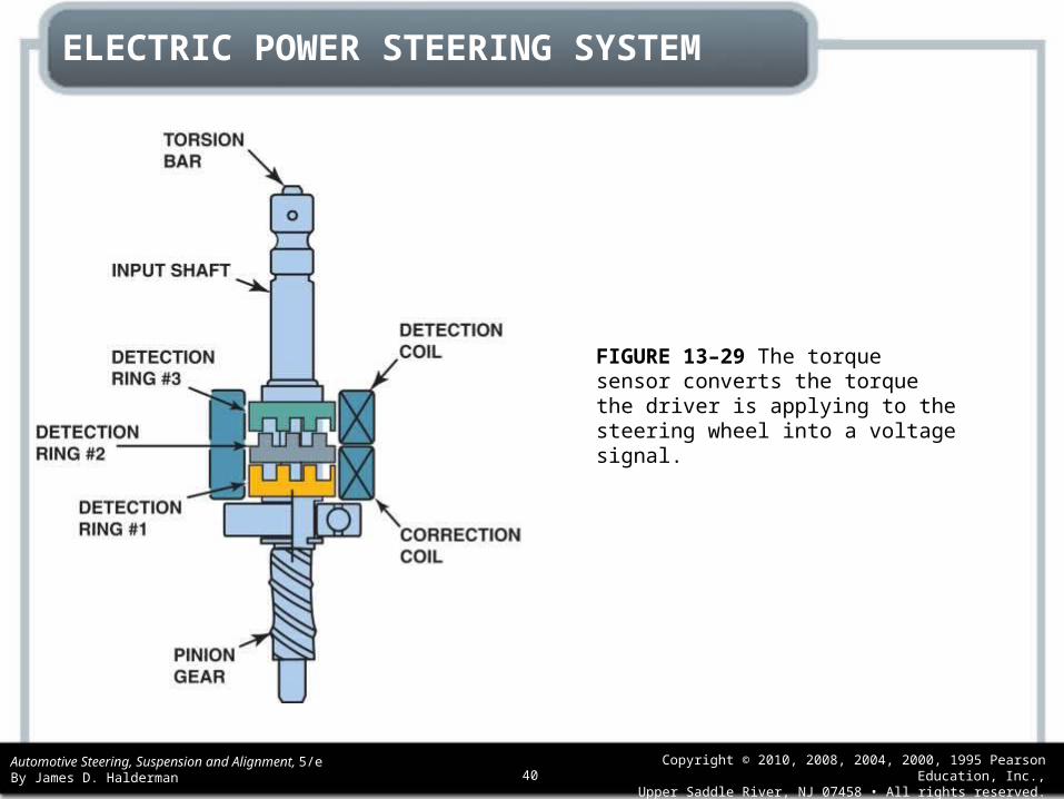
FIGURE 13–29 The torque sensor converts the torque the driver is applying to the steering wheel into a voltage signal.

Automotive Steering, Suspension and Alignment, 5/eBy James D. Halderman
Copyright © 2010, 2008, 2004, 2000, 1995 Pearson Education, Inc.,Upper Saddle River, NJ 07458 • All rights reserved.41
ELECTRIC POWER STEERING SYSTEM
FIGURE 13–30 The electric power steering in Toyota/Lexus SUVs uses a brushless DC motor around the rack of the unit and operates on 42 volts.

Automotive Steering, Suspension and Alignment, 5/eBy James D. Halderman
Copyright © 2010, 2008, 2004, 2000, 1995 Pearson Education, Inc.,Upper Saddle River, NJ 07458 • All rights reserved.42
ELECTRIC POWER STEERING SYSTEM
FIGURE 13–31 Photo of the electric power steering gear on A Lexus RX 400h taken from underneath the vehicle.

Automotive Steering, Suspension and Alignment, 5/eBy James D. Halderman
Copyright © 2010, 2008, 2004, 2000, 1995 Pearson Education, Inc.,Upper Saddle River, NJ 07458 • All rights reserved.43
ELECTRIC POWER STEERING SYSTEM
FIGURE 13–32 A cross-sectional view of a Honda electric power steering (EPS) gear.

Automotive Steering, Suspension and Alignment, 5/eBy James D. Halderman
Copyright © 2010, 2008, 2004, 2000, 1995 Pearson Education, Inc.,Upper Saddle River, NJ 07458 • All rights reserved.44
ELECTRIC POWER STEERING SYSTEM
FIGURE 13–33 Honda electric power steering unit cutaway.

Automotive Steering, Suspension and Alignment, 5/eBy James D. Halderman
Copyright © 2010, 2008, 2004, 2000, 1995 Pearson Education, Inc.,Upper Saddle River, NJ 07458 • All rights reserved.45
ELECTRIC POWER STEERING SYSTEM
FIGURE 13–34 The Power Steering Control Module (PSCM) is attached to the motor of the electric power steering assembly.

Automotive Steering, Suspension and Alignment, 5/eBy James D. Halderman
Copyright © 2010, 2008, 2004, 2000, 1995 Pearson Education, Inc.,Upper Saddle River, NJ 07458 • All rights reserved.46
ELECTRIC POWER STEERING SYSTEM
• STEERING SHAFT TORQUE SENSOR• STEERING WHEEL POSITION SENSOR• POWER STEERING MOTOR• POWER STEERING CONTROL MODULE
(PSCM)

Automotive Steering, Suspension and Alignment, 5/eBy James D. Halderman
Copyright © 2010, 2008, 2004, 2000, 1995 Pearson Education, Inc.,Upper Saddle River, NJ 07458 • All rights reserved.47
ELECTRIC POWER STEERING SYSTEM
FIGURE 13–35 Schematic showing the electric power steering and the torque/position sensor.

Automotive Steering, Suspension and Alignment, 5/eBy James D. Halderman
Copyright © 2010, 2008, 2004, 2000, 1995 Pearson Education, Inc.,Upper Saddle River, NJ 07458 • All rights reserved.48
SELF-PARKING SYSTEM
• Several vehicle manufacturers offer a self-parking feature that uses the electric power steering to steer the vehicle.
• The driver has control of the brakes. Most systems use the following sensors:• Wheel speed sensor (WSS)• Steering-angle sensor• Ultrasonic sensors, which are used to plot a course
into a parking space

Automotive Steering, Suspension and Alignment, 5/eBy James D. Halderman
Copyright © 2010, 2008, 2004, 2000, 1995 Pearson Education, Inc.,Upper Saddle River, NJ 07458 • All rights reserved.49
SELF-PARKING SYSTEMDIAGNOSIS AND TESTING
• Self-parking systems use many sensors to achieve the parking event, and a fault in any one sensor will disable self-parking.
• Before trying to diagnose a self-parking fault, be sure that the driver is operating the system as designed.
• For example, the self-parking event is cancelled if the accelerator pedal is depressed on some units.
• Always follow the factory-recommended diagnostic and testing procedures.
Automotive Steering, Suspension and Alignment, 5/eBy James D. Halderman
Copyright © 2010, 2008, 2004, 2000, 1995 Pearson Education, Inc.,Upper Saddle River, NJ 07458 • All rights reserved.50
ELECTROHYDRAULIC POWER STEERING
• Electrohydraulic power steering is used on the Chevrolet Silverado hybrid truck.
• The electrohydraulic power steering (EHPS) module controls the power steering motor, which has the function of providing hydraulic power to the brake booster and the steering gear.
• A secondary function includes the ability to improve fuel economy by operating on a demand basis and the ability to provide speed-dependent variable-effort steering.

Automotive Steering, Suspension and Alignment, 5/eBy James D. Halderman
Copyright © 2010, 2008, 2004, 2000, 1995 Pearson Education, Inc.,Upper Saddle River, NJ 07458 • All rights reserved.51
ELECTROHYDRAULIC POWER STEERING
• The EHPS module controls the EHPS powerpack, which is an integrated assembly consisting of the following components:• Electric motor• Hydraulic pump• Fluid reservoir• Reservoir cap• Fluid level sensor• Electronic controller• Electrical connectors

Automotive Steering, Suspension and Alignment, 5/eBy James D. Halderman
Copyright © 2010, 2008, 2004, 2000, 1995 Pearson Education, Inc.,Upper Saddle River, NJ 07458 • All rights reserved.52
ELECTROHYDRAULIC POWER STEERING
FIGURE 13–36 An electrohydraulic power steering assembly on a Chevrolet hybrid pickup truck.
Automotive Steering, Suspension and Alignment, 5/eBy James D. Halderman
Copyright © 2010, 2008, 2004, 2000, 1995 Pearson Education, Inc.,Upper Saddle River, NJ 07458 • All rights reserved.53
ELECTROHYDRAULIC POWER STEERINGEHPS MODULE
• The electrohydraulic power steering (EHPS) module is operated from the 36-volt (nominal) power supply.
• The EHPS module uses class 2 for serial communications.• A 125-amp, 36-volt fuse is used to protect the EHPS
module. • If this fuse were to blow open, the EHPS system would not
operate and communication codes would be set by the modules that communicate with the EHPS module.
• The Powertrain Control Module (PCM) is the gateway that translates controller area network (CAN) messages into class 2 messages when required for diagnostic purposes.
Automotive Steering, Suspension and Alignment, 5/eBy James D. Halderman
Copyright © 2010, 2008, 2004, 2000, 1995 Pearson Education, Inc.,Upper Saddle River, NJ 07458 • All rights reserved.54
POWER STEERING DIAGNOSIS AND TROUBLESHOOTING
• Power steering systems are generally very reliable, yet many problems, such as hard steering, are caused by not correcting simple service items such as the following:• A loose, worn, or defective power steering pump drive
belt• A bent or misaligned drive pulley• Low or contaminated power steering fluid• Broken or loose power steering pump mounting brackets• Underinflated tires.• Engine idle speed below specifications.• A defective power steering pressure switch• Internal steering gear mechanical binding.
Automotive Steering, Suspension and Alignment, 5/eBy James D. Halderman
Copyright © 2010, 2008, 2004, 2000, 1995 Pearson Education, Inc.,Upper Saddle River, NJ 07458 • All rights reserved.55
POWER STEERING DIAGNOSIS AND TROUBLESHOOTING
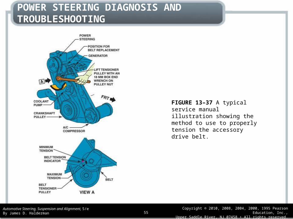
FIGURE 13–37 A typical service manual illustration showing the method to use to properly tension the accessory drive belt.

Automotive Steering, Suspension and Alignment, 5/eBy James D. Halderman
Copyright © 2010, 2008, 2004, 2000, 1995 Pearson Education, Inc.,Upper Saddle River, NJ 07458 • All rights reserved.56
The Visual Test
• Whenever diagnosing any power steering complaint, check the level and condition of the power steering fluid. Often this is best accomplished by putting your finger down into the power steering fluid reservoir and pulling it out to observe the texture and color of the fluid.
• A common problem with some power rack-andpinion units is the wearing of grooves in the housing by the Teflon sealing rings of the spool (control) valve. When this wear occurs, aluminum particles become suspended in the power steering fluid, giving it a grayish color and thickening the fluid.

Automotive Steering, Suspension and Alignment, 5/eBy James D. Halderman
Copyright © 2010, 2008, 2004, 2000, 1995 Pearson Education, Inc.,Upper Saddle River, NJ 07458 • All rights reserved.57
The Visual Test
• Normally clear power steering fluid that is found to be grayish in color and steering that is difficult when cold are clear indications as to what has occurred and why the steering is not functioning correctly.

Automotive Steering, Suspension and Alignment, 5/eBy James D. Halderman
Copyright © 2010, 2008, 2004, 2000, 1995 Pearson Education, Inc.,Upper Saddle River, NJ 07458 • All rights reserved.58
The Visual Test
FIGURE 13–38 A check of the power steering fluid should include inspecting not only the level but the condition and color of the fluid, which could indicate a possible problem with other components in the steering system.

Automotive Steering, Suspension and Alignment, 5/eBy James D. Halderman
Copyright © 2010, 2008, 2004, 2000, 1995 Pearson Education, Inc.,Upper Saddle River, NJ 07458 • All rights reserved.59
POWER STEERING DIAGNOSIS AND TROUBLESHOOTING
• POWER STEERING FLUID• POWER STEERING FLUID FLUSHING
PROCEDURE• BLEEDING AIR OUT OF THE SYSTEM• HOSE INSPECTION• PRESSURE TESTING• PUMP SERVICE

Automotive Steering, Suspension and Alignment, 5/eBy James D. Halderman
Copyright © 2010, 2008, 2004, 2000, 1995 Pearson Education, Inc.,Upper Saddle River, NJ 07458 • All rights reserved.60
POWER STEERING DIAGNOSIS AND TROUBLESHOOTING
FIGURE 13–39 Some power steering fluid is unique to the climate, such as this cold climate fluid recommended for use in General Motors vehicles when temperatures are low.
Automotive Steering, Suspension and Alignment, 5/eBy James D. Halderman
Copyright © 2010, 2008, 2004, 2000, 1995 Pearson Education, Inc.,Upper Saddle River, NJ 07458 • All rights reserved.61
POWER STEERING DIAGNOSIS AND TROUBLESHOOTING
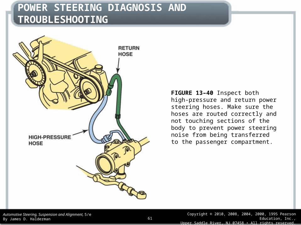
FIGURE 13–40 Inspect both high-pressure and return power steering hoses. Make sure the hoses are routed correctly and not touching sections of the body to prevent power steering noise from being transferred to the passenger compartment.

Automotive Steering, Suspension and Alignment, 5/eBy James D. Halderman
Copyright © 2010, 2008, 2004, 2000, 1995 Pearson Education, Inc.,Upper Saddle River, NJ 07458 • All rights reserved.62
POWER STEERING DIAGNOSIS AND TROUBLESHOOTING
FIGURE 13–41 A drawing showing how to connect a power steering analyzer to the system.

Automotive Steering, Suspension and Alignment, 5/eBy James D. Halderman
Copyright © 2010, 2008, 2004, 2000, 1995 Pearson Education, Inc.,Upper Saddle River, NJ 07458 • All rights reserved.63
POWER STEERING DIAGNOSIS AND TROUBLESHOOTING
FIGURE 13–42 A power steering analyzer that measures both pressure and volume. The shut-off valve is used to test the maximum pressure of the pump.

Automotive Steering, Suspension and Alignment, 5/eBy James D. Halderman
Copyright © 2010, 2008, 2004, 2000, 1995 Pearson Education, Inc.,Upper Saddle River, NJ 07458 • All rights reserved.64
POWER STEERING DIAGNOSIS AND TROUBLESHOOTING
FIGURE 13–43 Typical power steering pump showing the order of assembly. The high-pressure (outlet) hose attaches to the fitting (#16). The flow control valve can be removed from the pump by removing the fitting.

Automotive Steering, Suspension and Alignment, 5/eBy James D. Halderman
Copyright © 2010, 2008, 2004, 2000, 1995 Pearson Education, Inc.,Upper Saddle River, NJ 07458 • All rights reserved.65
POWER STEERING DIAGNOSIS AND TROUBLESHOOTING
FIGURE 13–44 Typical tools required to remove and install a drive pulley on a power steering pump. Often these tools can be purchased at a relatively low cost from automotive parts stores and will work on many different makes of vehicles.

Automotive Steering, Suspension and Alignment, 5/eBy James D. Halderman
Copyright © 2010, 2008, 2004, 2000, 1995 Pearson Education, Inc.,Upper Saddle River, NJ 07458 • All rights reserved.66
POWER STEERING DIAGNOSIS AND TROUBLESHOOTING
FIGURE 13–45 A typical submerged-type power steering pump. The pump is housed inside the fluid reservoir. (Courtesy of Chrysler Corporation)

Automotive Steering, Suspension and Alignment, 5/eBy James D. Halderman
Copyright © 2010, 2008, 2004, 2000, 1995 Pearson Education, Inc.,Upper Saddle River, NJ 07458 • All rights reserved.67
POWER STEERING DIAGNOSIS AND TROUBLESHOOTING
FIGURE 13–46 A punch is used to dislodge the retaining ring.

Automotive Steering, Suspension and Alignment, 5/eBy James D. Halderman
Copyright © 2010, 2008, 2004, 2000, 1995 Pearson Education, Inc.,Upper Saddle River, NJ 07458 • All rights reserved.68
POWER STEERING DIAGNOSIS AND TROUBLESHOOTING
FIGURE 13–47 The driveshaft attaches to the drive pulley at one end and is splined to the pump rotor at the other end. The vanes are placed in the slots of the rotor.

Automotive Steering, Suspension and Alignment, 5/eBy James D. Halderman
Copyright © 2010, 2008, 2004, 2000, 1995 Pearson Education, Inc.,Upper Saddle River, NJ 07458 • All rights reserved.69
POWER STEERING DIAGNOSIS AND TROUBLESHOOTING
FIGURE 13–48 The pump ring must be installed correctly. If it is installed upside down, the internal passages will not line up and the pump will have no output.
Automotive Steering, Suspension and Alignment, 5/eBy James D. Halderman
Copyright © 2010, 2008, 2004, 2000, 1995 Pearson Education, Inc.,Upper Saddle River, NJ 07458 • All rights reserved.70
POWER STEERING DIAGNOSIS AND TROUBLESHOOTING
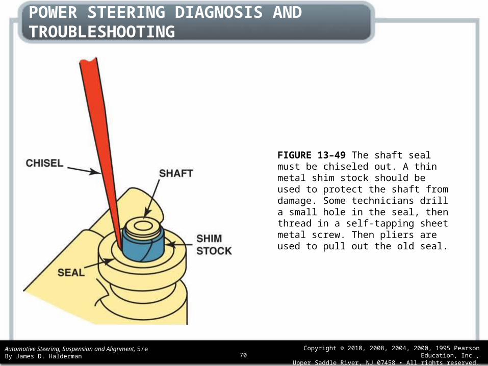
FIGURE 13–49 The shaft seal must be chiseled out. A thin metal shim stock should be used to protect the shaft from damage. Some technicians drill a small hole in the seal, then thread in a self-tapping sheet metal screw. Then pliers are used to pull out the old seal.

Automotive Steering, Suspension and Alignment, 5/eBy James D. Halderman
Copyright © 2010, 2008, 2004, 2000, 1995 Pearson Education, Inc.,Upper Saddle River, NJ 07458 • All rights reserved.71
Pocket the Ignition Key to Be Safe
• When replacing any steering gear such as a rackand- pinion steering unit, be sure that no one accidentally turns the steering wheel! If the steering wheel is turned without being connected to the steering gear, the airbag wire coil (clock spring) can become off center. This can cause the wiring to break when the steering wheel is rotated after the steering gear has been replaced. To help prevent this from occurring, simply remove the ignition key from the ignition (make sure the steering wheel is locked) and put it in your pocket while servicing the steering gear.

Automotive Steering, Suspension and Alignment, 5/eBy James D. Halderman
Copyright © 2010, 2008, 2004, 2000, 1995 Pearson Education, Inc.,Upper Saddle River, NJ 07458 • All rights reserved.72
SUMMARY
1. Always use a belt tension gauge when checking, replacing, or tightening a power steering drive belt. The proper power steering fluid should always be used to prevent possible seal or power steering hose failure.
2. Power steering troubles can usually be diagnosed using a power steering pressure gauge. Lower-than-normal pump pressure could be due to a weak (defective) power steering pump or internal leakage inside the steering gear itself. If the pressure reaches normal when the shut-off valve on the gauge is closed, then the problem is isolated to being a defective gear.
3. Care should be taken when repairing or replacing any steering gear assembly to follow the vehicle manufacturer’s recommended procedures exactly; do not substitute parts from one steering gear to another.

Automotive Steering, Suspension and Alignment, 5/eBy James D. Halderman
Copyright © 2010, 2008, 2004, 2000, 1995 Pearson Education, Inc.,Upper Saddle River, NJ 07458 • All rights reserved.73
REVIEW QUESTIONS
1. List five possible causes for hard steering.
2. Explain the procedure for flushing a power steering system.
3. Describe how to pressure test a power steering system.
4. Briefly describe adjustment and service procedures for a power rack-and-pinion steering unit.

Automotive Steering, Suspension and Alignment, 5/eBy James D. Halderman
Copyright © 2010, 2008, 2004, 2000, 1995 Pearson Education, Inc.,Upper Saddle River, NJ 07458 • All rights reserved.74
CHAPTER QUIZ
1. Two technicians are discussing the proper procedure for bleeding air from a power steering system. Technician A says that the front wheels of the vehicle should be lifted off the ground before bleeding. Technician B says that the steering wheel should be turned left and right with the engine off during the procedure. Which technician is correct?
a. Technician A onlyb. Technician B onlyc. Both Technicians A and Bd. Neither Technician A nor B

Automotive Steering, Suspension and Alignment, 5/eBy James D. Halderman
Copyright © 2010, 2008, 2004, 2000, 1995 Pearson Education, Inc.,Upper Saddle River, NJ 07458 • All rights reserved.75
CHAPTER QUIZ
2. A power steering pressure test is being performed, and the pressure is higher than specifications with the engine running and the steering wheel stationary in the straight-ahead position. Technician A says that a restricted high-pressure line could be the cause. Technician B says that internal leakage inside the steering gear or rack-and-pinion unit could be the cause. Which technician is correct?a. Technician A onlyb. Technician B onlyc. Both Technicians A and Bd. Neither Technician A nor B

Automotive Steering, Suspension and Alignment, 5/eBy James D. Halderman
Copyright © 2010, 2008, 2004, 2000, 1995 Pearson Education, Inc.,Upper Saddle River, NJ 07458 • All rights reserved.76
CHAPTER QUIZ
3. When pressure testing an hydraulic assisted power steering system, the highest pressures were greater than 50 PSI of each other. This indicates a problem with the ________.
a. Pump rotor
b. Pump vanes
c. Flow control valve
d. Defective hose
Automotive Steering, Suspension and Alignment, 5/eBy James D. Halderman
Copyright © 2010, 2008, 2004, 2000, 1995 Pearson Education, Inc.,Upper Saddle River, NJ 07458 • All rights reserved.77
CHAPTER QUIZ
4. Integral power steering gears use ________ for lubrication of the unit.
a. SAE 80W-90 gear lube
b. Chassis grease (NLGI #2)
c. Power steering fluid in the system
d. Molybdenum disulfide

Automotive Steering, Suspension and Alignment, 5/eBy James D. Halderman
Copyright © 2010, 2008, 2004, 2000, 1995 Pearson Education, Inc.,Upper Saddle River, NJ 07458 • All rights reserved.78
CHAPTER QUIZ
5. What can cause hard steering on a vehicle equipped with hydraulic power assisted steering system?
a. Low tire pressure
b. Slipping P.S. pump drive belt
c. Low or contaminated power steering fluid
d. Any of the above
Automotive Steering, Suspension and Alignment, 5/eBy James D. Halderman
Copyright © 2010, 2008, 2004, 2000, 1995 Pearson Education, Inc.,Upper Saddle River, NJ 07458 • All rights reserved.79
CHAPTER QUIZ
6. High-pressure hoses have to be used on the high-pressure side of the power steering system because pressures can reach as high as ________.
a. 200 PSI
b. 750 PSI
c. 1,500 PSI
d. 2,500 PSI

Automotive Steering, Suspension and Alignment, 5/eBy James D. Halderman
Copyright © 2010, 2008, 2004, 2000, 1995 Pearson Education, Inc.,Upper Saddle River, NJ 07458 • All rights reserved.80
CHAPTER QUIZ
7. Some vehicles are equipped to signal the computer whenever the power steering pressures increase so that the idle speed can be increased to prevent stalling during turns at low speeds. What component signals the computer?
a. Pressure-relief valve
b. Power steering pressure switch
c. Rotary valve
d. Flow control valve

Automotive Steering, Suspension and Alignment, 5/eBy James D. Halderman
Copyright © 2010, 2008, 2004, 2000, 1995 Pearson Education, Inc.,Upper Saddle River, NJ 07458 • All rights reserved.81
CHAPTER QUIZ
8. What type of motor is used in most electric power steering (EPS) systems?
a. AC brush type
b. DC brushless
c. Stepper
d. DC capacitor start

Automotive Steering, Suspension and Alignment, 5/eBy James D. Halderman
Copyright © 2010, 2008, 2004, 2000, 1995 Pearson Education, Inc.,Upper Saddle River, NJ 07458 • All rights reserved.82
CHAPTER QUIZ
9. Electronically controlled variable-assist power steering systems vary the amount of boost by ________.
a. Varying the pump output orifice size
b. Speeding up or slowing down the power steering pump
c. Changing the flow of fluid through the steering gear
d. Bypassing some of the fluid back into the reservoir

Automotive Steering, Suspension and Alignment, 5/eBy James D. Halderman
Copyright © 2010, 2008, 2004, 2000, 1995 Pearson Education, Inc.,Upper Saddle River, NJ 07458 • All rights reserved.83
CHAPTER QUIZ
10.Two technicians are discussing electric power steering (EPS) systems.Technician A says that some systems operate on 12 volts. Technician B says that some systems operate on 42 volts such as some hybrid electric vehicles. Which technician is correct?
a. Technician A only
b. Technician B only
c. Both Technicians A and B
d. Neither Technician A nor B