Chapter 13 Electromagnetic Inductioncremaldi/PHYS212/chapter13.pdf · Chapter 13 Electromagnetic...
15
Chapter 13 Electromagnetic Induction In this chapter we will study the following topics: -Faraday’s law of induction -Lenz’s rule -Electric field induced by a changing magnetic field -Eddy Currents -Electric Generators 1
Transcript of Chapter 13 Electromagnetic Inductioncremaldi/PHYS212/chapter13.pdf · Chapter 13 Electromagnetic...
Chapter 13 Electromagnetic Induction
In this chapter we will study the following topics:
-Faraday’s law of induction -Lenz’s rule -Electric field induced by a changing magnetic field -Eddy Currents -Electric Generators
1
cremaldi
Sticky Note
We found that currents produce magnetic fields, so it was naively thought that magnetic fields would produce currents! Not so simple. The chapter is about magnetic induction, how a magnetic field can induce a current.
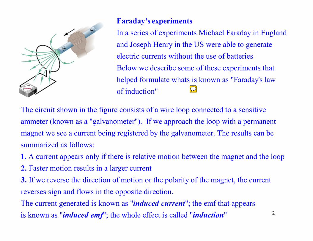
In a series of experiments Michael Faraday in England and Joseph Henry in the US were able to generate electric currents without the use of batteries Below we describe some of the
Faraday's experiments
se experiments thathelped formulate whats is known as "Faraday's lawof induction"
The circuit shown in the figure consists of a wire loop connected to a sensitiveammeter (known as a "galvanometer"). If we approach the loop with a permanent magnet we see a current being registered by the galvanometer. The results can be summarized as follows:
A current appears only if there is relative motion between the magnet and the loop Faster motion results in a larger current If we
1.2.3. reverse the direction of motion or the polarity of the magnet, the currentreverses sign and flows in the opposite direction. The current generated is known as " "; the emf that appears induced current is known as " "; the whole effect is called " "induced emf induction 2
cremaldi
Sticky Note
Faraday discovered that the a changing magnetic field produces a current in a coil. Read.
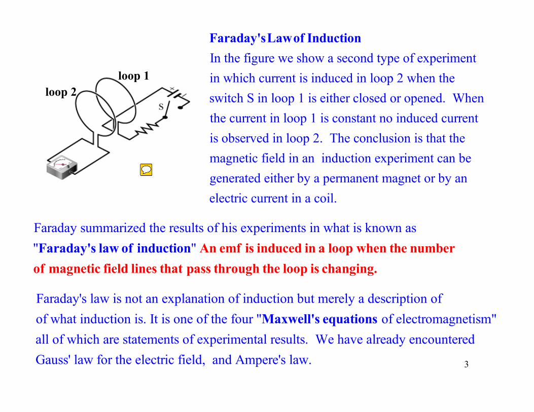
Faraday'sLawof InductionIn the figure we show a second type of experimentin which current is induced in loop 2 when the switch S in loop 1 is either closed or opened. Whenthe current in loop 1 is constant no induced current is observed in loop 2. The conclusion is that the magnetic field in an induction experiment can begenerated either by a permanent magnet or by anelectric current in a coil.
loop 1 loop 2
Faraday summarized the results of his experiments in what is known as"Faraday's law of induction" An emf is induced in a loop when the number of magnetic field lines that pass through the loop is changing.
Faraday's law is not an explanation of induction but merely a description of of what induction is. It is one of the four "Maxwell's equations of electromagnetism"all of which are statements of experimental results. We have already encounteredGauss' law for the electric field, and Ampere's law. 3
cremaldi
Sticky Note
Observation: When loop-1 is activated to produce a B-field, the number of magnetic flux lines increases in loop-2, inducing a current in the loop-2.
B!
n̂
dA
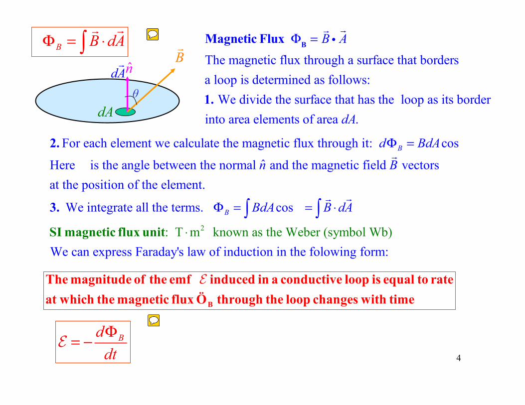
Magnetic Flux ΦB =!B i!A
The magnetic flux through a surface that bordersa loop is determined as follows: 1. We divide the surface that has the loop as its borderinto area elements of area dA.
For each element we calculate the magnetic flux through it: cos
ˆHere is the angle between the normal and the magnetic field vectorsat the position of the element.
We integrate a
Bd BdA
n B
Φ =2.
3.
!
2: T m known as the Weber (symbol
ll the terms. cos
We can express Faraday's law of induction in the folowin W
g b)
form:
B BdA B dAΦ = =
⋅
⋅∫ ∫SI magnetic flux unit
!!
B
The magnitude of the emf induced in a conductive loop is equal to rateat which the magnetic flux Ö through the loop changes with time
E
B B dAΦ = ⋅∫!!
BddtΦ= −E
4
d!Aθ
cremaldi
Sticky Note
Faraday reasoned that a changing magnetic flux through a loop would produce a current flow or EMF in the loop. The magnetic flux is defined as B *dA, similar to electric flux E*dA!
cremaldi
Sticky Note
Faraday's Law states that an EMF is produced in a loop when the magnetic flux through the loop changes.. The EMF opposes the change in flux, thus the negative sign.
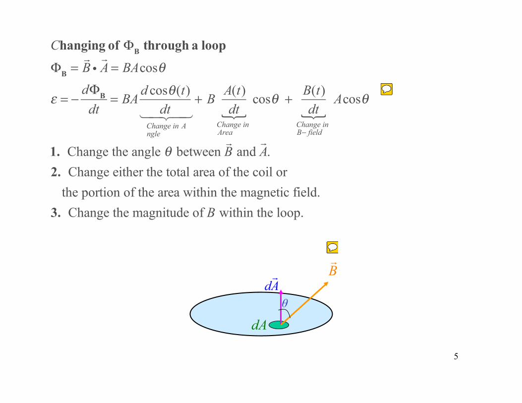
Changing of ΦB through a loop
ΦB =!B i!A = BAcosθ
ε = −dΦB
dt= BA d cosθ(t)
dtChange in Angle
" #$ %$+ B A(t)
dtChange inArea
&cosθ + B(t)
dtChange inB− field
&Acosθ
1. Change the angle θ between !B and
!A.
2. Change either the total area of the coil orthe portion of the area within the magnetic field.
3. Change the magnitude of B within the loop.
5
B!
dA
d!Aθ
cremaldi
Sticky Note
Taking the derivative we see that the emf can be produced by a change in field B, or a change in area A, or a change in angle between B and A.
cremaldi
Sticky Note
In the expression for magnetic flux BdA, the area vector dA is perpendicular to the surface. B points in an arbitrary. direction. This flux is similar to the electric flux through a surface EdA.
6
B!
n̂
loop
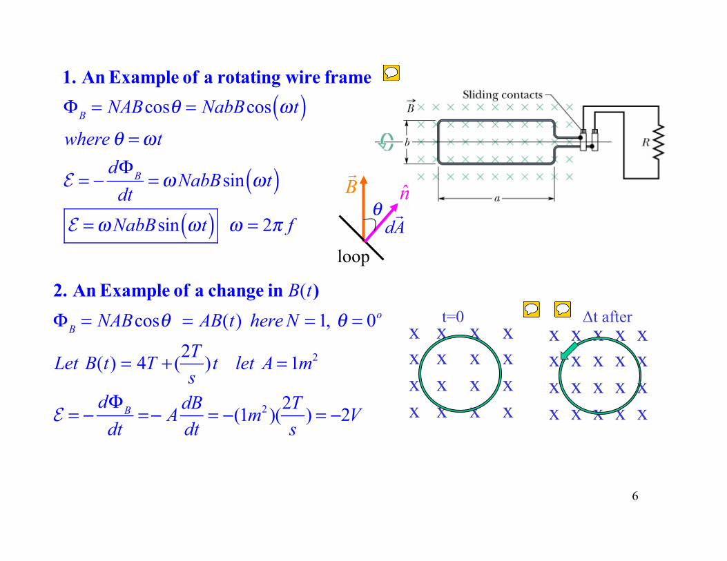
1. An Example of a rotating wire frame
ΦB = NABcosθ = NabBcos ωt( )where θ =ωt
E = −dΦB
dt=ωNabBsin ωt( )
E =ωNabBsin ωt( ) ω = 2π f d!A
θ
x x x x x x x x x x x x x x x x
x x x x x x x x x x x x x x x x x x x x
t=0 Δt after
2. An Example of a change in B(t)
ΦB = NABcosθ = AB(t) here N = 1, θ = 0o
Let B(t) = 4T + (2Ts
)t let A = 1m2
E = −dΦB
dt=− A
dBdt
= −(1m2 )(2Ts
) = −2V
cremaldi
Sticky Note
The turning hoop in the stationary B-field produces a sinusoidal EMF. This forms the principal of an electric generator, to be discussed later.
cremaldi
Sticky Note
The increasing B-field inside the hoop (2 new flux lines appearing per second) creates a circulating CCW current I. This current produced an EMF = IR. R is the hoop resistance.
cremaldi
Sticky Note
The CCW current flows in a direction which opposes the incoming 2 new flux lines, and tries to cancel them. This is called Lenz's rule.
7
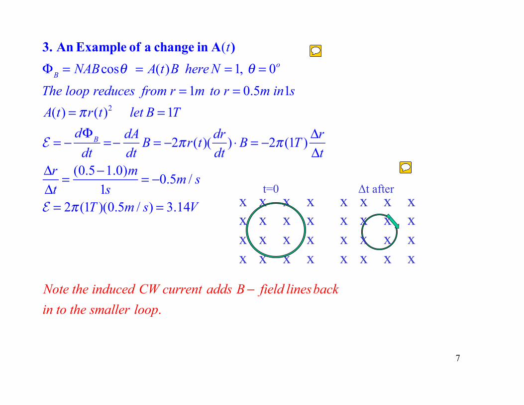
3. An Example of a change in A(t)
ΦB = NABcosθ = A(t)B here N = 1, θ = 0o
The loop reduces from r = 1m to r = 0.5m in1s
A(t) = πr(t)2 let B = 1T
E = −dΦB
dt=− dA
dtB = −2πr(t)(
drdt
) ⋅B = −2π (1T )ΔrΔt
ΔrΔt
= (0.5−1.0)m1s
= −0.5m / s
E = 2π (1T )(0.5m / s) = 3.14V
Note the induced CW current adds B − field linesbackin to the smaller loop.
x x x x x x x x x x x x x x x x
t=0 Δt after x x x x x x x x x x x x x x x x
cremaldi
Sticky Note
In this example the hoop size changes, becoming smaller. This action induces a CW current which tries to restore the missing field lines to the smaller hoop.
cremaldi
Sticky Note
To add fhe missing field lines a CW current appears as the hoop is shrinking trying to add the 2 missing field lines back in.
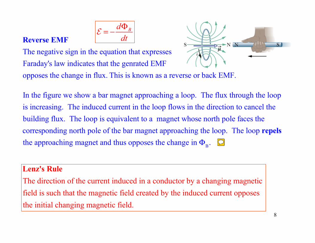
BddtΦ= −E
Reverse EMFThe negative sign in the equation that expresses Faraday's law indicates that the genrated EMF opposes the change in flux. This is known as a reverse or back EMF.
Lenz's RuleThe direction of the current induced in a conductor by a changing magnetic field is such that the magnetic field created by the induced current opposes the initial changing magnetic field.
In the figure we show a bar magnet approaching a loop. The flux through the loopis increasing. The induced current in the loop flows in the direction to cancel the building flux. The loop is equivalent to a magnet whose north pole faces the corresponding north pole of the bar magnet approaching the loop. The loop repelsthe approaching magnet and thus opposes the change in ΦB.
8
cremaldi
Sticky Note
Lenz's rule states that the current induced in circuit (loop) will tend to act to in a direction which restores any change in magnetic flux in the circuit (loop).
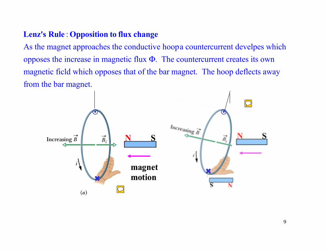
Lenz's Rule : Opposition to flux changeAs the magnet approaches the conductive hoopa countercurrent develpes which opposes the increase in magnetic flux Φ. The countercurrent creates its own magnetic ficld which opposes that of the bar magnet. The hoop deflects away from the bar magnet.
9
!
✖
!
✖
cremaldi
Sticky Note
In this example, as the magnet is pushed in to he hoop. The hoop reacts to repel the new field lines, forming a current which produces an opposing magnetic field. The hoop is deflected!
cremaldi
Sticky Note
The current directions are at first confusing but the current goes in at the bottom and out at the top. This forms a 2ndary magnet with its N pole facing right, opposing the primary insertion magnet's N-pole.
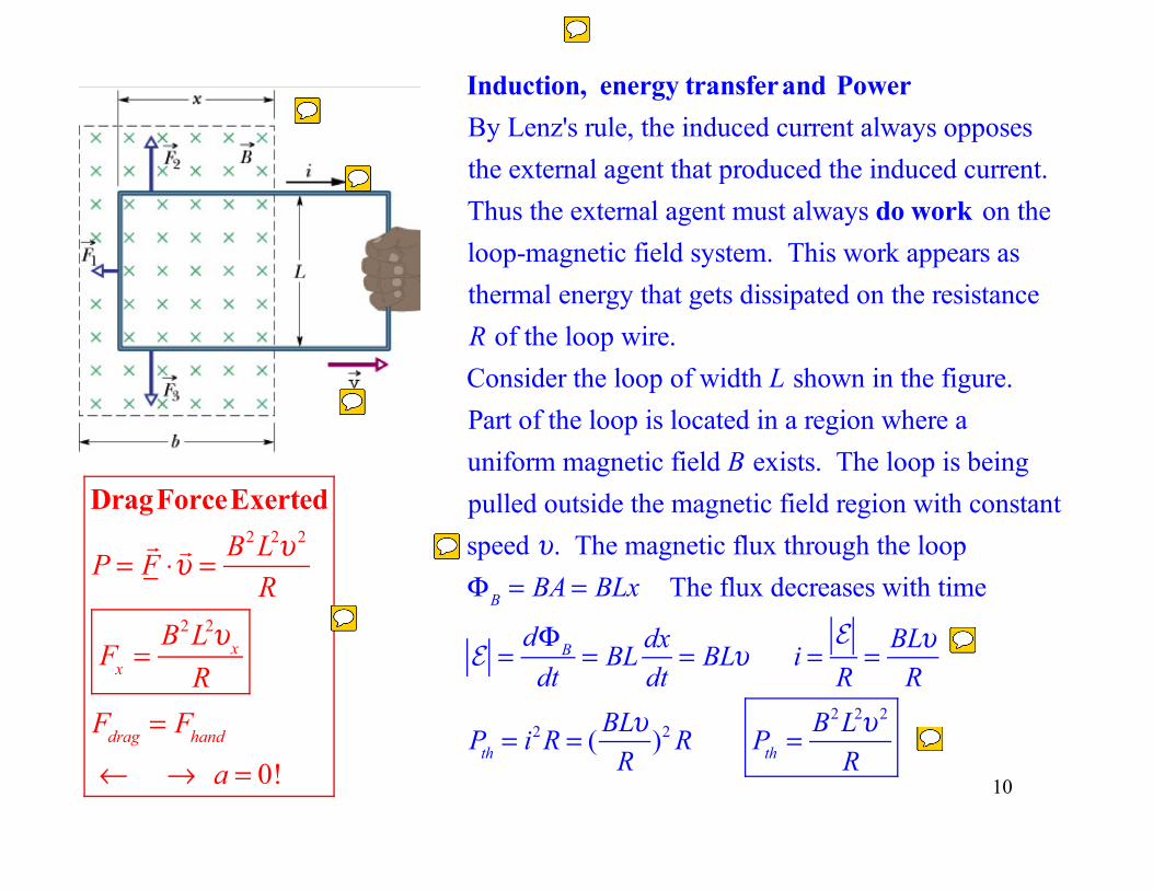
Induction, energy transferand PowerBy Lenz's rule, the induced current always opposesthe external agent that produced the induced current.Thus the external agent must always do work on theloop-magnetic field system. This work appears asthermal energy that gets dissipated on the resistance R of the loop wire. Consider the loop of width L shown in the figure. Part of the loop is located in a region where a uniform magnetic field B exists. The loop is beingpulled outside the magnetic field region with constantspeed υ. The magnetic flux through the loop ΦB = BA = BLx The flux decreases with time
E =dΦB
dt= BL
dxdt
= BLυ i =E
R= BLυ
R
Pth = i2R = (BLυ
R)2 R Pth =
B2L2υ 2
R
10
DragForceExerted
P =!F ⋅!υ = B2L2υ 2
R
Fx =B2L2υx
RFdrag = Fhand
← → a = 0!
cremaldi
Sticky Note
The vertical forces balance, F2=F3 The horizontal forces also balance! F1=Fpull. The stronger Fpull, the greater the current flow, the greater F2 ! Alway in balance.
cremaldi
Sticky Note
Since F2=Fpull there is no acceleration, so the velocity vx is constant. Remember a=dv/dt=0
cremaldi
Sticky Note
From Power = F v the exerted force can be determined.
cremaldi
Sticky Note
The power P is dissipated in the resistor and body heat.
cremaldi
Sticky Note
Here A=Lx is the hoop area so the Flux = BA = BLx .
cremaldi
Sticky Note
A time derivative of the Flux=BLx gives the EMF=BLv and current I=V/R. Power is P=IV or P = I^2 R.
cremaldi
Sticky Note
It will a take force, work and, power to insert or remove a conducting hoop from a magnetic field. This is another example of an EMF produced by an area change in a circuit.
cremaldi
Sticky Note
As the hoop is pulled to the right, currents flow in the wire creating a counter or drag force to the left.
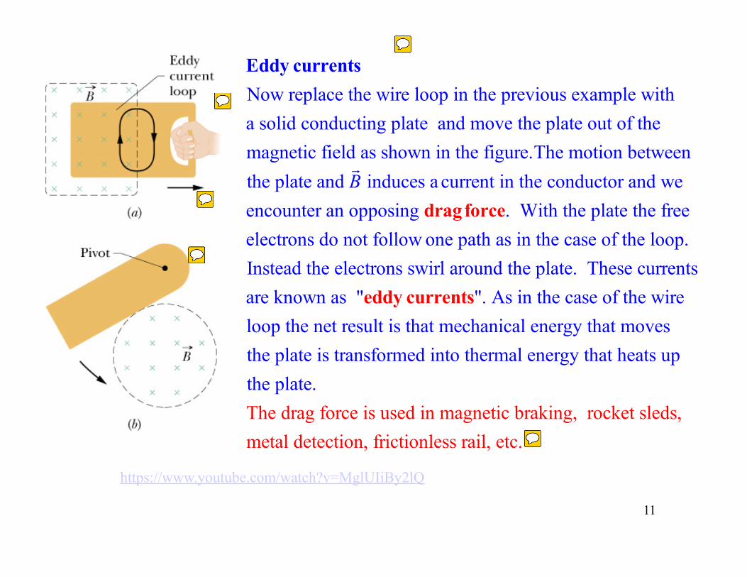
Eddy currentsNow replace the wire loop in the previous example with a solid conducting plate and move the plate out of the magnetic field as shown in the figure.The motion between the plate and
!B induces a current in the conductor and we
encounter an opposing dragforce. With the plate the free electrons do not follow one path as in the case of the loop. Instead the electrons swirl around the plate. These currents are known as "eddy currents". As in the case of the wire loop the net result is that mechanical energy that moves the plate is transformed into thermal energy that heats up the plate.The drag force is used in magnetic braking, rocket sleds,metal detection, frictionless rail, etc.
https://www.youtube.com/watch?v=MglUIiBy2lQ
11
cremaldi
Sticky Note
EMF currents are also produced in metal plates such as Al and Cu as they move in magnetic fields. As the plate is pulled out an "Eddy current" forms' which works to reestablish the missing field lines by Lenz's rule.
cremaldi
Sticky Note
The Eddy current produces a drag force which exactly counters the applied force (hand) moving the plate.
cremaldi
Sticky Note
Note the CW current in the plate, produces a magnetic field in to the page, attempting to reestablish the missing field lines as the plate is removed. The resultant force Fdrag = v x B is to the left and opposite to Fhand.
cremaldi
Sticky Note
The drag force due to Eddy currents has many practical applications. You can read more in your text and online.
cremaldi
Sticky Note
The swinging plate will be stopped by the Eddy current generated when it swings in to the magnetic field. As it swings in a CCW current circulation forms which tries to cancel the new field lines. The two magnetic fields, one permanent and one induced, act to bring the plate to a stop.
12
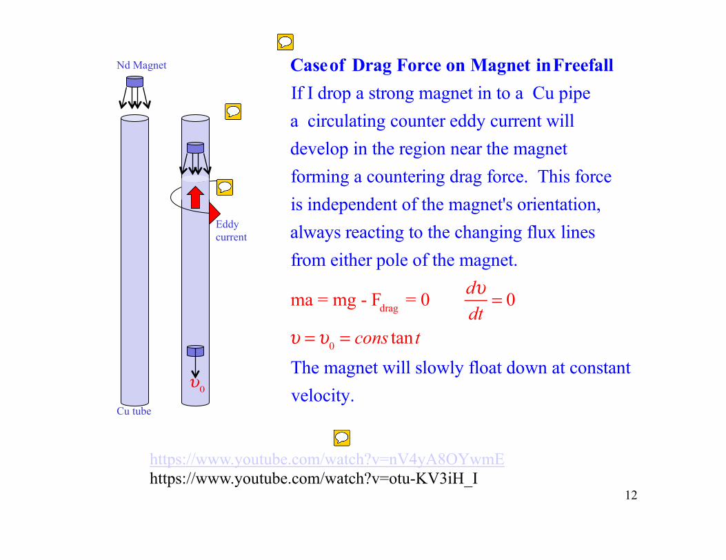
Eddy current
Cu tube
Nd Magnet
Caseof Drag Force on Magnet inFreefallIf I drop a strong magnet in to a Cu pipe a circulating counter eddy current will develop in the region near the magnetforming a countering drag force. This forceis independent of the magnet's orientation, always reacting to the changing flux lines from either pole of the magnet.
ma = mg - Fdrag = 0dυdt
= 0
υ =υ0 = cons tan t
The magnet will slowly float down at constant velocity. υ0
https://www.youtube.com/watch?v=nV4yA8OYwmE https://www.youtube.com/watch?v=otu-KV3iH_I
cremaldi
Sticky Note
The Nd magnet will drift slowly down the Cu tube at a constant velocity, the drag force due to Eddy currents canceling gravity's F=mg.
cremaldi
Sticky Note
A convincing demonstration of Eddy currents in Cu or Al can be made by dropping a strong neodenium Nd magnet in to a Cu tube.
cremaldi
Sticky Note
The dropping Nd magnet creates a changing flux in the walls of the tube. The Eddy current creates a 2ndary B-field which opposes the Nd field. The magnet drifts down with constant velocity.
cremaldi
Sticky Note
Do watch the video links.
13
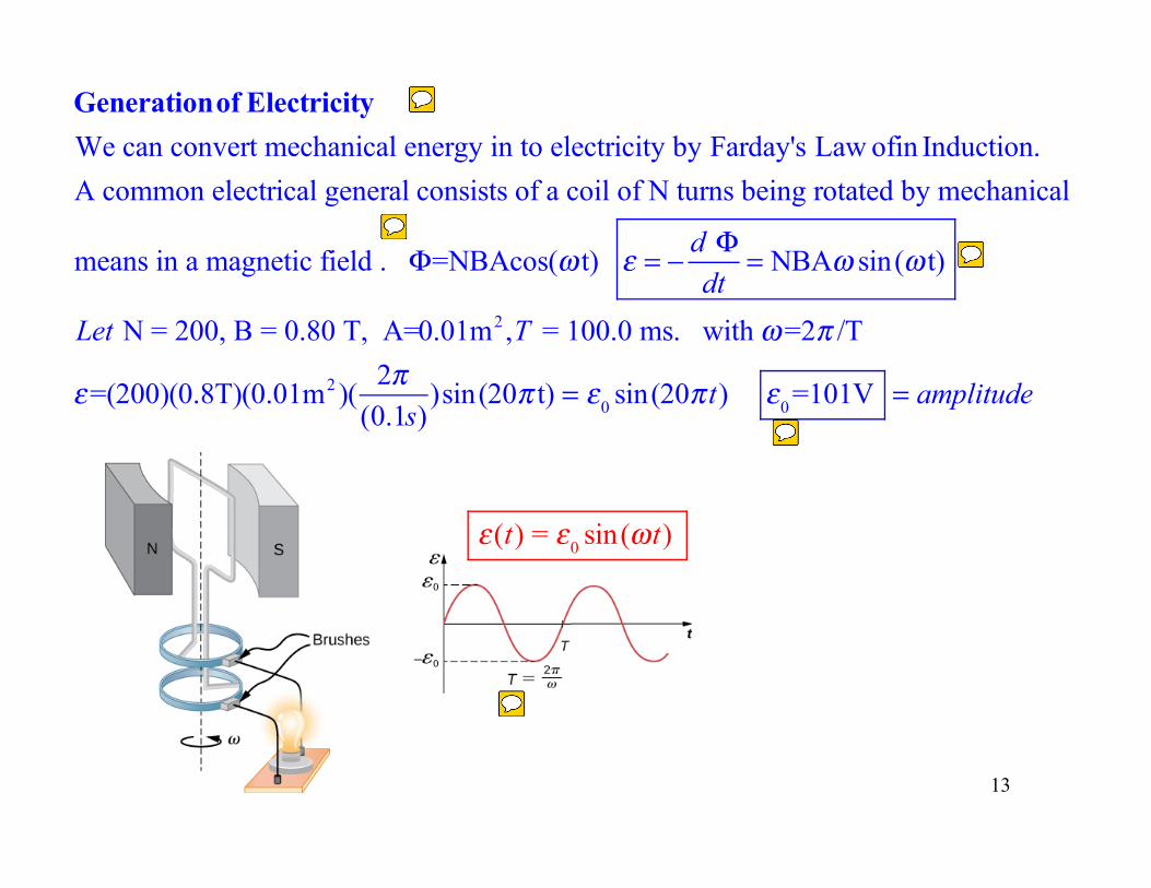
Generationof ElectricityWe can convert mechanical energy in to electricity by Farday's Law ofin Induction.A common electrical general consists of a coil of N turns being rotated by mechanical
means in a magnetic field . Φ=NBAcos(ω t) ε = − d Φdt
= NBAω sin(ω t)
Let N = 200, B = 0.80 T, A=0.01m2,T = 100.0 ms. with ω=2π /T
ε=(200)(0.8T)(0.01m2 )(2π
(0.1s))sin(20π t) = ε0 sin(20π t) ε0 =101V = amplitude
ε(t) = ε0 sin(ωt)
cremaldi
Sticky Note
Electric power is generated by rotating a coil in a magnetic field. The flux and EMF are defined by Faraday's law of induction. This is an example of AC power generation.
cremaldi
Sticky Note
The period of the wave is the time to complete one cycle. Power in the US comes to us at f=60hz so: T=1/f=(1/60) s.
cremaldi
Sticky Note
The wave amplitude is Eo=NABw.N=number of turnsA=areaB=magnetic fieldw=angular freqency of rotation
cremaldi
Sticky Note
A sinusoidal (AC) EMF is produced.
cremaldi
Sticky Note
The flux is B*A = NBAcos(wt)
14
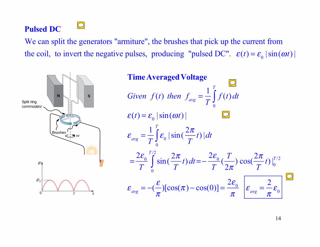
Pulsed DCWe can split the generators "armiture", the brushes that pick up the current fromthe coil, to invert the negative pulses, producing "pulsed DC". ε(t) = ε0 | sin(ωt) |
Time AveragedVoltage
Given f (t) then favg =1T
f (t)dt0
T
∫ε(t) = ε0 | sin(ωt) |
εavg =1T
ε0 | sin(2πT
t) |0
T
∫ dt
=2ε0
Tsin(
2πT
t)0
T /2
∫ dt=−2ε0
T(
T2π
) cos(2πT
t) |0T /2
εavg = −(επ
)[cos(π )− cos(0)]=2ε0
πεavg =
2πε0
cremaldi
Sticky Note
The negative half of the AC power cycle can be flipped (inverted) to be positive by a split armature-pickup brush arrangement. This is called "pulsed DC".Armatures, commutators, brushes are complicated! EE students beware.
cremaldi
Sticky Note
This is how one finds the time average of a function of time f(t), by integrating and dividing by the integration period T.
cremaldi
Sticky Note
Follow this integrstion to determine the EMF averaged over one cycle of pulsed DC.
cremaldi
Sticky Note
The average EMF is about 2/3 Eo. It is difficult to use this rippling -DC? The rippling period is T/2, every half cycle. Later we will show how pulsed DC can be smoothed out to provide an almost flat DC, similar to a battery,

STOP HERE
15
