Chapter 12: Physical Storage Systems · 2019-06-25 · Database System Concepts - 7th Edition 12.5...
30
Database System Concepts, 7 th Ed. ©Silberschatz, Korth and Sudarshan See www.db-book.com for conditions on re-use Chapter 12: Physical Storage Systems
Transcript of Chapter 12: Physical Storage Systems · 2019-06-25 · Database System Concepts - 7th Edition 12.5...

Database System Concepts, 7th Ed.©Silberschatz, Korth and Sudarshan
See www.db-book.com for conditions on re-use
Chapter 12: Physical Storage Systems

©Silberschatz, Korth and Sudarshan12.2Database System Concepts - 7th Edition
Classification of Physical Storage Media
Can differentiate storage into:• volatile storage: loses contents when power is
switched off• non-volatile storage:
Contents persist even when power is switched off. Includes secondary and tertiary storage, as well as
batter-backed up main-memory.
Factors affecting choice of storage media include• Speed with which data can be accessed• Cost per unit of data• Reliability

©Silberschatz, Korth and Sudarshan12.3Database System Concepts - 7th Edition
Storage Hierarchy

©Silberschatz, Korth and Sudarshan12.4Database System Concepts - 7th Edition
Storage Hierarchy (Cont.)
primary storage: Fastest media but volatile (cache, main memory).
secondary storage: next level in hierarchy, non-volatile, moderately fast access time• also called on-line storage • E.g. flash memory, magnetic disks
tertiary storage: lowest level in hierarchy, non-volatile, slow access time• also called off-line storage and used for archival storage• e.g. magnetic tape, optical storage• Magnetic tape
Sequential access, 1 to 12 TB capacity A few drives with many tapes Juke boxes with petabytes (1000’s of TB) of storage

©Silberschatz, Korth and Sudarshan12.5Database System Concepts - 7th Edition
Storage Interfaces
Disk interface standards families• SATA (Serial ATA)
SATA 3 supports data transfer speeds of up to 6 gigabits/sec• SAS (Serial Attached SCSI)
SAS Version 3 supports 12 gigabits/sec• NVMe (Non-Volatile Memory Express) interface
Works with PCIe connectors to support lower latency and higher transfer rates
Supports data transfer rates of up to 24 gigabits/sec Disks usually connected directly to computer system In Storage Area Networks (SAN), a large number of disks are
connected by a high-speed network to a number of servers In Network Attached Storage (NAS) networked storage provides a
file system interface using networked file system protocol, instead of providing a disk system interface

©Silberschatz, Korth and Sudarshan12.6Database System Concepts - 7th Edition
Magnetic Hard Disk Mechanism
Schematic diagram of magnetic disk drive Photo of magnetic disk drive

©Silberschatz, Korth and Sudarshan12.7Database System Concepts - 7th Edition
Magnetic Disks
Read-write head Surface of platter divided into circular tracks
• Over 50K-100K tracks per platter on typical hard disks Each track is divided into sectors.
• A sector is the smallest unit of data that can be read or written.• Sector size typically 512 bytes• Typical sectors per track: 500 to 1000 (on inner tracks) to 1000 to
2000 (on outer tracks) To read/write a sector
• disk arm swings to position head on right track• platter spins continually; data is read/written as sector passes under
head Head-disk assemblies
• multiple disk platters on a single spindle (1 to 5 usually)• one head per platter, mounted on a common arm.
Cylinder i consists of ith track of all the platters

©Silberschatz, Korth and Sudarshan12.8Database System Concepts - 7th Edition
Magnetic Disks (Cont.)
Disk controller – interfaces between the computer system and the disk drive hardware.• accepts high-level commands to read or write a sector • initiates actions such as moving the disk arm to the right track and
actually reading or writing the data• Computes and attaches checksums to each sector to verify that
data is read back correctly If data is corrupted, with very high probability stored checksum
won’t match recomputed checksum• Ensures successful writing by reading back sector after writing it• Performs remapping of bad sectors

©Silberschatz, Korth and Sudarshan12.9Database System Concepts - 7th Edition
Performance Measures of Disks
Access time – the time it takes from when a read or write request is issued to when data transfer begins. Consists of: • Seek time – time it takes to reposition the arm over the correct track.
Average seek time is 1/2 the worst case seek time.• Would be 1/3 if all tracks had the same number of sectors, and we
ignore the time to start and stop arm movement 4 to 10 milliseconds on typical disks
• Rotational latency – time it takes for the sector to be accessed to appear under the head. 4 to 11 milliseconds on typical disks (5400 to 15000 r.p.m.) Average latency is 1/2 of the above latency.
• Overall latency is 5 to 20 msec depending on disk model Data-transfer rate – the rate at which data can be retrieved from
or stored to the disk.• 25 to 200 MB per second max rate, lower for inner tracks

©Silberschatz, Korth and Sudarshan12.10Database System Concepts - 7th Edition
Performance Measures (Cont.)
Disk block is a logical unit for storage allocation and retrieval• 4 to 16 kilobytes typically
Smaller blocks: more transfers from disk Larger blocks: more space wasted due to partially filled blocks
Sequential access pattern• Successive requests are for successive disk blocks• Disk seek required only for first block
Random access pattern• Successive requests are for blocks that can be anywhere on disk• Each access requires a seek• Transfer rates are low since a lot of time is wasted in seeks
I/O operations per second (IOPS)• Number of random block reads that a disk can support per second• 50 to 200 IOPS on current generation magnetic disks

©Silberschatz, Korth and Sudarshan12.11Database System Concepts - 7th Edition
Performance Measures (Cont.)
Mean time to failure (MTTF) – the average time the disk is expected to run continuously without any failure.• Typically 3 to 5 years• Probability of failure of new disks is quite low, corresponding to a
“theoretical MTTF” of 500,000 to 1,200,000 hours for a new disk E.g., an MTTF of 1,200,000 hours for a new disk means that
given 1000 relatively new disks, on an average one will fail every 1200 hours
• MTTF decreases as disk ages

©Silberschatz, Korth and Sudarshan12.12Database System Concepts - 7th Edition
Flash Storage
NOR flash vs NAND flash NAND flash
• used widely for storage, cheaper than NOR flash• requires page-at-a-time read (page: 512 bytes to 4 KB)
20 to 100 microseconds for a page read Not much difference between sequential and random
read• Page can only be written once
Must be erased to allow rewrite Solid state disks
• Use standard block-oriented disk interfaces, but store data on multiple flash storage devices internally
• Transfer rate of up to 500 MB/sec using SATA, and up to 3 GB/sec using NVMe PCIe

©Silberschatz, Korth and Sudarshan12.13Database System Concepts - 7th Edition
Flash Storage (Cont.) Erase happens in units of erase block
• Takes 2 to 5millisecs• Erase block typically 256 KB to 1 MB (128 to 256 pages)
Remapping of logical page addresses to physical page addresses avoids waiting for erase
Flash translation table tracks mapping• also stored in a label field of flash page• remapping carried out by flash translation layer
After 100,000 to 1,000,000 erases, erase block becomes unreliable and cannot be used• wear leveling
Logical Page Address
Physical Page Address
Flash Translation Table
Logical address and valid bitstored with eachphysical page (extra bytes)
Page write

©Silberschatz, Korth and Sudarshan12.14Database System Concepts - 7th Edition
SSD Performance Metrics
Random reads/writes per second• Typical 4 KB reads: 10,000 reads per second (10,000 IOPS)• Typical 4KB writes: 40,000 IOPS• SSDs support parallel reads
Typical 4KB reads: • 100,000 IOPS with 32 requests in parallel (QD-32) on
SATA• 350,000 IOPS with QD-32 on NVMe PCIe
Typical 4KB writes:• 100,000 IOPS with QD-32, even higher on some models
Data transfer rate for sequential reads/writes• 400 MB/sec for SATA3, 2 to 3 GB/sec using NVMe PCIe
Hybrid disks: combine small amount of flash cache with larger magnetic disk

©Silberschatz, Korth and Sudarshan12.15Database System Concepts - 7th Edition
Storage Class Memory
3D-XPoint memory technology pioneered by Intel Available as Intel Optane
• SSD interface shipped from 2017 Allows lower latency than flash SSDs
• Non-volatile memory interface announced in 2018 Supports direct access to words, at speeds comparable to
main-memory speeds
©Silberschatz, Korth and Sudarshan12.16Database System Concepts - 7th Edition
RAID
RAID: Redundant Arrays of Independent Disks • disk organization techniques that manage a large numbers of disks,
providing a view of a single disk of high capacity and high speed by using multiple disks in parallel, high reliability by storing data redundantly, so that data can be
recovered even if a disk fails
The chance that some disk out of a set of N disks will fail is much higher than the chance that a specific single disk will fail.• E.g., a system with 100 disks, each with MTTF of 100,000 hours (approx.
11 years), will have a system MTTF of 1000 hours (approx. 41 days)• Techniques for using redundancy to avoid data loss are critical with large
numbers of disks

©Silberschatz, Korth and Sudarshan12.17Database System Concepts - 7th Edition
Improvement of Reliability via Redundancy
Redundancy – store extra information that can be used to rebuild information lost in a disk failure
E.g., Mirroring (or shadowing)• Duplicate every disk. Logical disk consists of two physical disks.• Every write is carried out on both disks
Reads can take place from either disk• If one disk in a pair fails, data still available in the other
Data loss would occur only if a disk fails, and its mirror disk also fails before the system is repaired• Probability of combined event is very small
Except for dependent failure modes such as fire or building collapse or electrical power surges
Mean time to data loss depends on mean time to failure, and mean time to repair• E.g. MTTF of 100,000 hours, mean time to repair of 10 hours
gives mean time to data loss of 500*106 hours (or 57,000 years) for a mirrored pair of disks (ignoring dependent failure modes)

©Silberschatz, Korth and Sudarshan12.18Database System Concepts - 7th Edition
Improvement in Performance via Parallelism
Two main goals of parallelism in a disk system: 1. Load balance multiple small accesses to increase throughput2. Parallelize large accesses to reduce response time.
Improve transfer rate by striping data across multiple disks. Bit-level striping – split the bits of each byte across multiple disks
• In an array of eight disks, write bit i of each byte to disk i.• Each access can read data at eight times the rate of a single disk.• But seek/access time worse than for a single disk
Bit level striping is not used much any more
Block-level striping – with n disks, block i of a file goes to disk (imod n) + 1• Requests for different blocks can run in parallel if the blocks reside on
different disks• A request for a long sequence of blocks can utilize all disks in parallel
©Silberschatz, Korth and Sudarshan12.19Database System Concepts - 7th Edition
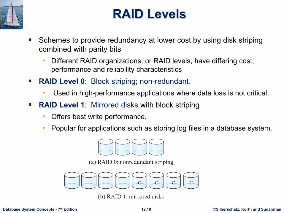
RAID Levels
Schemes to provide redundancy at lower cost by using disk striping combined with parity bits• Different RAID organizations, or RAID levels, have differing cost,
performance and reliability characteristics
RAID Level 0: Block striping; non-redundant.• Used in high-performance applications where data loss is not critical.
RAID Level 1: Mirrored disks with block striping• Offers best write performance. • Popular for applications such as storing log files in a database system.

©Silberschatz, Korth and Sudarshan12.20Database System Concepts - 7th Edition
RAID Levels (Cont.)
Parity blocks: Parity block j stores XOR of bits from block j of each disk• When writing data to a block j, parity block j must also be computed
and written to disk Can be done by using old parity block, old value of current block
and new value of current block (2 block reads + 2 block writes) Or by recomputing the parity value using the new values of blocks
corresponding to the parity block• More efficient for writing large amounts of data sequentially
• To recover data for a block, compute XOR of bits from all other blocks in the set including the parity block

©Silberschatz, Korth and Sudarshan12.21Database System Concepts - 7th Edition
RAID Levels (Cont.)
RAID Level 5: Block-Interleaved Distributed Parity; partitions data and parity among all N + 1 disks, rather than storing data in N disks and parity in 1 disk.• E.g., with 5 disks, parity block for nth set of blocks is stored on disk
(n mod 5) + 1, with the data blocks stored on the other 4 disks.

©Silberschatz, Korth and Sudarshan12.22Database System Concepts - 7th Edition
RAID Levels (Cont.)
RAID Level 5 (Cont.)• Block writes occur in parallel if the blocks and their parity blocks
are on different disks.
RAID Level 6: P+Q Redundancy scheme; similar to Level 5, but stores two error correction blocks (P, Q) instead of single parity block to guard against multiple disk failures. • Better reliability than Level 5 at a higher cost
Becoming more important as storage sizes increase

©Silberschatz, Korth and Sudarshan12.23Database System Concepts - 7th Edition
RAID Levels (Cont.)
Other levels (not used in practice):• RAID Level 2: Memory-Style Error-Correcting-Codes (ECC)
with bit striping.• RAID Level 3: Bit-Interleaved Parity• RAID Level 4: Block-Interleaved Parity; uses block-level
striping, and keeps a parity block on a separate parity disk for corresponding blocks from N other disks. RAID 5 is better than RAID 4, since with RAID 4 with random
writes, parity disk gets much higher write load than other disks and becomes a bottleneck

©Silberschatz, Korth and Sudarshan12.24Database System Concepts - 7th Edition
Choice of RAID Level
Factors in choosing RAID level• Monetary cost• Performance: Number of I/O operations per second, and
bandwidth during normal operation• Performance during failure• Performance during rebuild of failed disk
Including time taken to rebuild failed disk RAID 0 is used only when data safety is not important
• E.g. data can be recovered quickly from other sources

©Silberschatz, Korth and Sudarshan12.25Database System Concepts - 7th Edition
Choice of RAID Level (Cont.)
Level 1 provides much better write performance than level 5• Level 5 requires at least 2 block reads and 2 block writes to write
a single block, whereas Level 1 only requires 2 block writes
Level 1 had higher storage cost than level 5 Level 5 is preferred for applications where writes are sequential
and large (many blocks), and need large amounts of data storage RAID 1 is preferred for applications with many random/small
updates Level 6 gives better data protection than RAID 5 since it can
tolerate two disk (or disk block) failures• Increasing in importance since latent block failures on one disk,
coupled with a failure of another disk can result in data loss with RAID 1 and RAID 5.
©Silberschatz, Korth and Sudarshan12.26Database System Concepts - 7th Edition
Hardware Issues
Software RAID: RAID implementations done entirely in software, with no special hardware support
Hardware RAID: RAID implementations with special hardware• Use non-volatile RAM to record writes that are being executed• Beware: power failure during write can result in corrupted disk
E.g. failure after writing one block but before writing the second in a mirrored system
Such corrupted data must be detected when power is restored• Recovery from corruption is similar to recovery from
failed disk• NV-RAM helps to efficiently detected potentially
corrupted blocks Otherwise all blocks of disk must be read and
compared with mirror/parity block
©Silberschatz, Korth and Sudarshan12.27Database System Concepts - 7th Edition
Hardware Issues (Cont.) Latent failures: data successfully written earlier gets damaged
• can result in data loss even if only one disk fails
Data scrubbing:• continually scan for latent failures, and recover from copy/parity
Hot swapping: replacement of disk while system is running, without power down• Supported by some hardware RAID systems, • reduces time to recovery, and improves availability greatly
Many systems maintain spare disks which are kept online, and used as replacements for failed disks immediately on detection of failure• Reduces time to recovery greatly
Many hardware RAID systems ensure that a single point of failure will not stop the functioning of the system by using • Redundant power supplies with battery backup• Multiple controllers and multiple interconnections to guard against
controller/interconnection failures

©Silberschatz, Korth and Sudarshan12.28Database System Concepts - 7th Edition
Optimization of Disk-Block Access
Buffering: in-memory buffer to cache disk blocks Read-ahead: Read extra blocks from a track in anticipation that
they will be requested soon Disk-arm-scheduling algorithms re-order block requests so that
disk arm movement is minimized • elevator algorithm
R1 R5 R2 R4R3R6
Inner track Outer track
©Silberschatz, Korth and Sudarshan12.30Database System Concepts - 7th Edition
End of Chapter 12

©Silberschatz, Korth and Sudarshan12.31Database System Concepts - 7th Edition
Magnetic Tapes
Hold large volumes of data and provide high transfer rates• Few GB for DAT (Digital Audio Tape) format, 10-40 GB with DLT
(Digital Linear Tape) format, 100 GB+ with Ultrium format, and 330 GB with Ampex helical scan format
• Transfer rates from few to 10s of MB/s
Tapes are cheap, but cost of drives is very high Very slow access time in comparison to magnetic and optical
disks• limited to sequential access.• Some formats (Accelis) provide faster seek (10s of seconds) at
cost of lower capacity
Used mainly for backup, for storage of infrequently used information, and as an off-line medium for transferring information from one system to another.
Tape jukeboxes used for very large capacity storage• Multiple petabyes (1015 bytes)