Chapter 10 Reliability of Safety Systems
40
Introduction and System Definition Failure Analysis Testing The IEC 61508 Standard Chapter 10 Reliability of Safety Systems Marvin Rausand [email protected] RAMS Group Department of Production and ality Engineering NTNU (Version 0.1) Marvin Rausand (RAMS Group) System Reliability Theory (Version 0.1) 1 / 40
Transcript of Chapter 10 Reliability of Safety Systems

Introduction and System Definition Failure Analysis Testing The IEC 61508 Standard
Chapter 10Reliability of Safety Systems
Marvin [email protected]
RAMS GroupDepartment of Production and �ality Engineering
NTNU
(Version 0.1)
Marvin Rausand (RAMS Group) System Reliability Theory (Version 0.1) 1 / 40

Introduction and System Definition Failure Analysis Testing The IEC 61508 Standard
Slides related to the book
System Reliability TheoryModels, Statistical Methods,and Applications
Wiley, 2004
Homepage of the book:http://www.ntnu.edu/ross/books/srt
Marvin Rausand (RAMS Group) System Reliability Theory (Version 0.1) 2 / 40

Introduction and System Definition Failure Analysis Testing The IEC 61508 Standard
What is a safety-instrumented system?
A safety-instrumented system (SIS) is a designated system that implementsthe required safety functions necessary to achieve or maintain a safe statefor some equipment (an EUC). A SIS consists of three types of elements:
I Detectors (or sensors)I Logic solver (e.g., one or more computers)I Actuating items (e.g., valves, brakes)
Computer
Detectors Actuating itemsLogic solver
Marvin Rausand (RAMS Group) System Reliability Theory (Version 0.1) 3 / 40

Introduction and System Definition Failure Analysis Testing The IEC 61508 Standard
Alternative terms
I Safety-instrumented system (SIS); used in IEC 61511 and in the U.S.National Standard ANSI/ISA 84.01
I Electrical/electronic/programmable electronic (E/E/PE) safety-relatedsystem; used in IEC 61508
I Instrumented protective systemI Programmable electronic system (PES)I Safety-related system (SRS)I Safety shutdown (SSD) systemI Emergency shutdown (ESD) system
Marvin Rausand (RAMS Group) System Reliability Theory (Version 0.1) 4 / 40

Introduction and System Definition Failure Analysis Testing The IEC 61508 Standard
Equipment under control
Z Equipment under control (EUC): Equipment, machinery, apparatus orplant used for manufacturing, process, transportation, medical or otheractivities.
Z EUC control system: System which responds to input signals from theprocess and/or from an operator and generates output signals causing theEUC to operate in the desired manner. [Also called basic process controlsystem (BPCS)]
Z EUC risk: Risk arising from the EUC or its interaction with the EUCcontrol system.
[Definitions from IEC 61508-4]
Marvin Rausand (RAMS Group) System Reliability Theory (Version 0.1) 5 / 40

Introduction and System Definition Failure Analysis Testing The IEC 61508 Standard
What is functional safety?
Z Functional safety: is part of the overall safety relating to the EUC andthe EUC control system which depends on the correct functioning of theE/E/PE safety-related systems, other technology safety-related systems andexternal risk reduction facilities.
[Definition from IEC 61508-4]
Marvin Rausand (RAMS Group) System Reliability Theory (Version 0.1) 6 / 40

Introduction and System Definition Failure Analysis Testing The IEC 61508 Standard
Requirements to functional safety
Two types of requirements are necessary to achieve functional safety:
1. Safety function requirements: Requirements for the safety functionsthat have to be performed by the SIS.
2. Safety integrity requirements: Requirements related to the probabilitythat the safety function will perform satisfactorily. These requirementsmay be derived from a risk assessment of the system.
Marvin Rausand (RAMS Group) System Reliability Theory (Version 0.1) 7 / 40

Introduction and System Definition Failure Analysis Testing The IEC 61508 Standard
Safe state
Z Safe state: A state of the EUC when safety is achieved [IEC 61508-4]
NoteIn going from a potentially hazardous condition to the final safe state, the EUCmay have to go through a number of intermediate safe states. For some situationsa safe state exists only so long as the EUC is continuously controlled. Suchcontinuous control may be for a short or an indefinite period of time.
Marvin Rausand (RAMS Group) System Reliability Theory (Version 0.1) 8 / 40

Introduction and System Definition Failure Analysis Testing The IEC 61508 Standard
Layer of protection
Z Layer of protection (LOP): An independent mechanism that reduces riskby control, prevention, or mitigation. A LOP consists of a grouping ofequipment and/or administrative controls that function in concert withother LOPs to control or mitigate risk.
Examples of LOPs are:
I Basic process control system (BPCS) [EUC control system]
I Alarms with defined operator response
I Pressure relief devices
I Safety-instrumented systems (SIS)
I Deluge systems for fire or fume release
I Physical protection (e.g., fire walls)
I Evacuation procedures
A LOP that perform its function with a high degree of reliability may qualify as anindependent protection layer (IPL).
Marvin Rausand (RAMS Group) System Reliability Theory (Version 0.1) 9 / 40

Introduction and System Definition Failure Analysis Testing The IEC 61508 Standard
LOP characteristics
A LOP should have the following characteristics:I Specificity - A LOP is designed to prevent or mitigate the consequences
of one potentially hazardous event. Multiple causes may lead to thesame hazardous event, and therefore multiple event scenarios mayinitiate action by a LOP.
I Independence - A LOP is independent of other LOPs if it can bedemonstrated that there is no potential for common cause failureswith any other claimed LOPs.
I Dependability - The LOP can be counted on to do what it was designedto do by addressing both random hardware and systematic failuresduring its design.
I Auditability - A LOP is designed to facilitate regular validation of theprotective functions.
Marvin Rausand (RAMS Group) System Reliability Theory (Version 0.1) 10 / 40

Introduction and System Definition Failure Analysis Testing The IEC 61508 Standard
Examples of safety-instrumented systems
I Emergency shutdown (ESD) systems in a hazardous chemical processplant
I Automatic train stop (ATS) system in railwaysI Guard interlocking and emergency stopping systems for machineryI Dynamic positioning systems for ships and semisubmersible platformI Fly-by-wire operations of aircra� flight control surfacesI Anti-lock brakes on automobilesI Air-bag systems in automobiles
Marvin Rausand (RAMS Group) System Reliability Theory (Version 0.1) 11 / 40

Introduction and System Definition Failure Analysis Testing The IEC 61508 Standard
Main SIS functions
1. When a predefined process demand (deviation) occurs in the EUC, thedeviation shall be detected by the SIS sensors, and the requiredactuating items shall be activated and fulfill their intended functions.
2. The SIS shall not be activated spuriously, that is, without the presenceof a predefined process demand (deviation) in the EUC.
Marvin Rausand (RAMS Group) System Reliability Theory (Version 0.1) 12 / 40

Introduction and System Definition Failure Analysis Testing The IEC 61508 Standard
Failure definitions
I Dangerous failure - has the potential to put the SIS in a hazardous orfail-to-function state.
I Safe failure - does not have the potential to put the SIS in a hazardousor fail-to-function state.
A detected failure is a failure that is detected by the diagnostic tests orthrough normal operation.
Marvin Rausand (RAMS Group) System Reliability Theory (Version 0.1) 13 / 40

Introduction and System Definition Failure Analysis Testing The IEC 61508 Standard
Failure classification – 1
SIS failures may be classified as:I Dangerous (D) failures
• Dangerous undetected (DU) failures• Dangerous detected (DD) failures
I Safe (S) failures• Safe undetected (SU) failures• Safe detected (SD) failures
Dangerous (D)
Failure
Safe (S)
Dangerous detected (DD)
Dangerous undetected (DU)
Safedetected (SD)
Safeundetected (SU)
Marvin Rausand (RAMS Group) System Reliability Theory (Version 0.1) 14 / 40

Introduction and System Definition Failure Analysis Testing The IEC 61508 Standard
Failure classification – 2
Failures may also be classified according to the cause of the failure:I Random hardware failures
• Aging failures• Stress failures
I Systematic failures• Design failures• Interaction failures
Random hardware(physical)
Failure
Systematic(nonphysical)
Ageing Stress Design Interaction
Marvin Rausand (RAMS Group) System Reliability Theory (Version 0.1) 15 / 40

Introduction and System Definition Failure Analysis Testing The IEC 61508 Standard
Systematic failures
Z Systematic failure: A failure that is related in a deterministic way to acertain cause, and which can only be eliminated by a modification of thedesign or of the manufacturing process, operational procedures,documentation or other relevant factors.
Examples of systematic failure causes include:I Human errors in safety requirements specification, design,
manufacture, installation and operation of hardwareI Human errors in design and/or implementation of so�ware
Marvin Rausand (RAMS Group) System Reliability Theory (Version 0.1) 16 / 40
Introduction and System Definition Failure Analysis Testing The IEC 61508 Standard
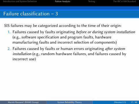
Failure classification – 3
SIS failures may be categorized according to the time of their origin:
1. Failures caused by faults originating before or during system installation(e.g., so�ware specification and program faults, hardwaremanufacturing faults and incorrect selection of components)
2. Failures caused by faults or human errors originating a�er systeminstallation (e.g., random hardware failures, and failures caused byincorrect use)
Marvin Rausand (RAMS Group) System Reliability Theory (Version 0.1) 17 / 40

Introduction and System Definition Failure Analysis Testing The IEC 61508 Standard
Failure rates
The following failure rates are used in the quantitative analyses:
Failure Rate Type of FailureλS Safe failuresλSD Safe detectable failuresλSU Safe undetectable failuresλD Dangerous failuresλDD Dangerous detectable failuresλDU Dangerous undetectable failures
Marvin Rausand (RAMS Group) System Reliability Theory (Version 0.1) 18 / 40
Introduction and System Definition Failure Analysis Testing The IEC 61508 Standard
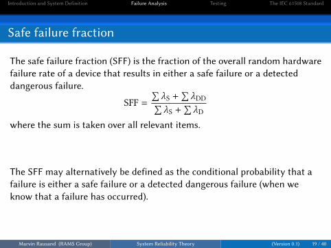
Safe failure fraction
The safe failure fraction (SFF) is the fraction of the overall random hardwarefailure rate of a device that results in either a safe failure or a detecteddangerous failure.
SFF =∑λS +
∑λDD∑
λS +∑λD
where the sum is taken over all relevant items.
The SFF may alternatively be defined as the conditional probability that afailure is either a safe failure or a detected dangerous failure (when weknow that a failure has occurred).
Marvin Rausand (RAMS Group) System Reliability Theory (Version 0.1) 19 / 40

Introduction and System Definition Failure Analysis Testing The IEC 61508 Standard
FMEDA
A Failure Modes, E�ects and Diagnostic Analysis (FMEDA) is an extensionof a traditional FMECA to identify online diagnostic techniques.
Id. Component Function Failuremode
Failurecauses
Failureeffects
Criticality Failurerate λ
Detectable(yes/no)
Diagnostic(descr.)
ModeD/S
λSD λSUλDDλDU Remarks
Marvin Rausand (RAMS Group) System Reliability Theory (Version 0.1) 20 / 40

Introduction and System Definition Failure Analysis Testing The IEC 61508 Standard
Causes of dangerous failures
Dangerous failures may arise from:I Incorrect specification of the system, hardware or so�wareI Omissions in the safety requirements specification (e.g., failure to
develop all relevant safety functions during di�erent modes ofoperation)
I Random hardware failure mechanismsI Systematic hardware failure mechanismsI So�ware errorsI Common cause failuresI Human errorI Environmental influences (e.g., electromagnetic, temperature,
mechanical phenomena)I Supply system voltage disturbances (e.g., loss of supply, reduced
voltages)Marvin Rausand (RAMS Group) System Reliability Theory (Version 0.1) 21 / 40

Introduction and System Definition Failure Analysis Testing The IEC 61508 Standard
Diagnostic testing
There are two main diagnostic testing techniques:
1. Reference diagnostic can be carried out with a single circuit and isbased on specific characteristics of the SIS, like voltage, currents, signaltiming, signal sequence, and temperature.
2. Comparison diagnostic compares data between two or more SIS units.If a failure occurs in the circuitry, processor or memory of one SIS unit,there will be di�erences between the data tables in that unit whencompared to another unit.
Marvin Rausand (RAMS Group) System Reliability Theory (Version 0.1) 22 / 40

Introduction and System Definition Failure Analysis Testing The IEC 61508 Standard
Diagnostic coverage – 1
Diagnostic coverage (DC) is defined as the ratio of the detected failure rateto the total failure rate of the component or subsystem as detected bydiagnostic tests. Diagnostic coverage does not include any faults detectedby proof tests. [IEC 61511-1]
DC =∑λDD∑λD
The DC may also be interpreted as the conditional probability that a failurewill be detected by diagnostic testing (when a failure occurs).
NoteDiagnostic coverage may exist for the whole or parts of a SIS. For example,diagnostic coverage may exist for sensors and/or logic system and/or final elements.
Marvin Rausand (RAMS Group) System Reliability Theory (Version 0.1) 23 / 40

Introduction and System Definition Failure Analysis Testing The IEC 61508 Standard
Diagnostic coverage – 2
For some applications it is necessary to distinguish between the diagnosticcoverage for dangerous and safe failures.
Let:
DCD = the diagnostic coverage for dangerous failures
DCS = the diagnostic coverage for safe failures
[Based on Goble and Brombacher 1999]
Marvin Rausand (RAMS Group) System Reliability Theory (Version 0.1) 24 / 40

Introduction and System Definition Failure Analysis Testing The IEC 61508 Standard
Proof testing
A proof test is a test performed to reveal undetected faults in asafety-instrumented system so that, if necessary, the system can be restoredto its designed functionality.
Marvin Rausand (RAMS Group) System Reliability Theory (Version 0.1) 25 / 40

Introduction and System Definition Failure Analysis Testing The IEC 61508 Standard
A generic standard
IEC 61508 “Functional safety of electrical/ electronic/ programmableelectronic (E/E/PE) safety-related systems” is a generic standard thatapplies to all safety-related systems using electrical, electronic, andprogrammable electronic devices irrespective of the application sector.
Examples of application sectors within the scope are:I Process industries (emergency shutdown systems, fire and gas
detection systems)I Manufacturing industries (industrial robots, machine tools)I Transportation (automatic train stop systems, braking systems)I Medical (electro-mechanical apparatus)
Marvin Rausand (RAMS Group) System Reliability Theory (Version 0.1) 26 / 40

Introduction and System Definition Failure Analysis Testing The IEC 61508 Standard
Objectives of IEC 61508
I To facilitate the development of application sector standards such as• IEC 61511 - for the process industry sector• IEC 62061 - for machinery systems
I To enable the development of E/E/PE safety-related systems whereapplication sector international standards do not exist.
Marvin Rausand (RAMS Group) System Reliability Theory (Version 0.1) 27 / 40

Introduction and System Definition Failure Analysis Testing The IEC 61508 Standard
IEC 61508 has seven parts
IEC 61508 has seven parts:
1. General requirements
2. Requirements for E/E/PE safety-related systems
3. So�ware requirements
4. Definitions and abbreviations
5. Examples of methods for determination of safety integrity levels
6. Guidelines on the application of IEC 61508-2 and IEC 61508-3
7. Overview of techniques and measures
Marvin Rausand (RAMS Group) System Reliability Theory (Version 0.1) 28 / 40

Introduction and System Definition Failure Analysis Testing The IEC 61508 Standard
Overall safety lifecycle – 1
IEC 61508 introduces the concept of an Overall Safety Lifecycle (see nextframe) to ensure that all activities necessary to achieve the required safetyintegrity level are performed. For each phase the standard specifies:
I The objectives to be achievedI The requirements to meet the objectiveI The scope of each phaseI The required inputs to the phaseI The deliverables required for each phase
Marvin Rausand (RAMS Group) System Reliability Theory (Version 0.1) 29 / 40

Introduction and System Definition Failure Analysis Testing The IEC 61508 Standard
Overall safety lifecycle – 2
1 Concept
2Overall scope
definition
3Hazard and risk
analysis
4Overall safety requirements
5Safety requirements
allocation
6 Overalloperation andmaintenance
planning
7 Overallsafety
validationplanning
8 Overallinstallation andcommissioning
planning
Overall planning 9Safety related
systems:E/E/PES
Realisation(see E/E/PES
safety lifecycle)
10Safety related
systems:other technology
Realisation
11External risk
reductionfacilities
Realisation
12Overall installationand commissioning
13Overall safety
validation
14Overall operation,
maintenance and repair
16Decommissioning
or disposal
15Overall modification
and retrofit
Back to appropriateoverall safety lifecycle
phase
Marvin Rausand (RAMS Group) System Reliability Theory (Version 0.1) 30 / 40

Introduction and System Definition Failure Analysis Testing The IEC 61508 Standard
Risk reduction: General concepts
Partial risk coveredby other technology
safety-related systems
Partial risk coveredby E/E/PE
safety-relatedsystems
Partial risk coveredby esternal risk
reduction facilities
Risk reduction achieved by all safety-relatedsystems and external risk reduction facilities
Tolerablerisk
Residualrisk
EUCrisk
Necessary risk reduction
Actual risk reduction
Increasing risk
Marvin Rausand (RAMS Group) System Reliability Theory (Version 0.1) 31 / 40

Introduction and System Definition Failure Analysis Testing The IEC 61508 Standard
Risk and safety integrity concepts
External riskreductionfacilities
Consequenceof hazardous
event
Frequencyof hazardous
event
EUCrisk
E/E/PEsafety-related
systems
Other technology
safety-relatedsystems
Tolerablerisk target
Necessary risk reduction
Safety integrity of external risk reduction facilities andsafety-related systems matched to the necessary risk
reduction
EUC and theEUC control
system
Marvin Rausand (RAMS Group) System Reliability Theory (Version 0.1) 32 / 40

Introduction and System Definition Failure Analysis Testing The IEC 61508 Standard
Allocation of safety requirements
Other technologysafety-related systems
External riskreduction facilities
E/E/PEsafety-related system
# 2
E/E/PEsafety-related system
# 1
E/E/PEsafety-related system
# 2
E/E/PEsafety-related system
# 1
E/E/PEsafety-related system
# 1
E/E/PEsafety-related system
# 2
Allocation of each safetyfunction and its associated
safety integrity requirements
For design requirements for individualE/E/PE safety-related systems, see IEC 61508-2
Method of specifyingsafety integrityrequirements
a) Necessary riskreduction
c) Safety integritylevels
b) Necessary riskreduction
Marvin Rausand (RAMS Group) System Reliability Theory (Version 0.1) 33 / 40

Introduction and System Definition Failure Analysis Testing The IEC 61508 Standard
Safety integrity level – 1
Z Safety integrity: The probability that a SIS will satisfactorily perform therequired safety functions under all the stated conditions within a statedperiod of time.
Z Safety integrity level (SIL): A discrete level (one out of a possible four) forspecifying the safety integrity requirements of the safety functions to beallocated to the SIS, where SIL 4 is the highest level and SIL 1 is the lowestlevel.
Marvin Rausand (RAMS Group) System Reliability Theory (Version 0.1) 34 / 40

Introduction and System Definition Failure Analysis Testing The IEC 61508 Standard
Safety-instrumented function
IEC 61508 details the requirements necessary to achieve each safetyintegrity level. A safety function that is implemented by a SIS is o�en calleda safety-instrumented function (SIF).
A SIS will usually implement more than one SIF. If the safety integrityrequirements for these SIFs di�er, the requirements applicable to thehighest relevant SIL shall apply for the entire SIS, unless there is su�icientindependence of implementation between the various SIFs.
Marvin Rausand (RAMS Group) System Reliability Theory (Version 0.1) 35 / 40

Introduction and System Definition Failure Analysis Testing The IEC 61508 Standard
Safety integrity level – 2
Low Demand Mode of High Demand Mode orSafety Operationa (Aver. probability Continuous Mode of
Integrity of failure to perform its Operationb (Probability of aLevel (SIL) design function on demand) dangerous failure per hour)
4 ≥ 10−5 to < 10−4 ≥ 10−9 to < 10−83 ≥ 10−4 to < 10−3 ≥ 10−8 to < 10−72 ≥ 10−3 to < 10−2 ≥ 10−7 to < 10−61 ≥ 10−2 to < 10−1 ≥ 10−6 to < 10−5
a) Low demand mode means that the frequency of demands for operation of the SIS isnot greater than once per year, and not greater than twice the proof-test frequency.
b) High demand mode means that the frequency of demands for operation of the SIS isgreater than once per year or greater than twice the proof-test frequency.
Marvin Rausand (RAMS Group) System Reliability Theory (Version 0.1) 36 / 40
Introduction and System Definition Failure Analysis Testing The IEC 61508 Standard
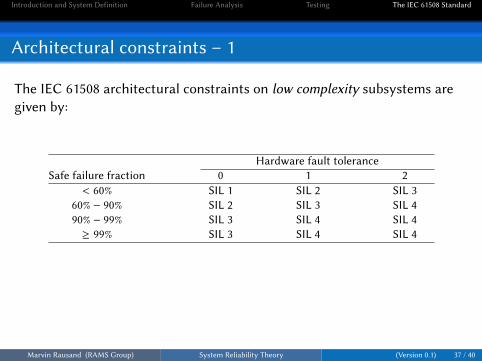
Architectural constraints – 1
The IEC 61508 architectural constraints on low complexity subsystems aregiven by:
Hardware fault toleranceSafe failure fraction 0 1 2
< 60% SIL 1 SIL 2 SIL 360% − 90% SIL 2 SIL 3 SIL 490% − 99% SIL 3 SIL 4 SIL 4≥ 99% SIL 3 SIL 4 SIL 4
Marvin Rausand (RAMS Group) System Reliability Theory (Version 0.1) 37 / 40

Introduction and System Definition Failure Analysis Testing The IEC 61508 Standard
Architectural constraints – 2
The IEC 61508 architectural constraints on complex subsystems are given by:
Hardware fault toleranceSafe failure fraction 0 1 2
< 60% N/A SIL 1 SIL 260% − 90% SIL 1 SIL 2 SIL 390% − 99% SIL 2 SIL 3 SIL 4≥ 99% SIL 3 SIL 4 SIL 4
N/A means “Not allowed”
Marvin Rausand (RAMS Group) System Reliability Theory (Version 0.1) 38 / 40

Introduction and System Definition Failure Analysis Testing The IEC 61508 Standard
Architectural constraints – 3
The architectural constraints (AC) are those constraints that are imposed byIEC 61508-2 to limit the SIL that can be claimed for any safety function onthe basis of its hardware fault tolerance and its safe failure fraction (SFF).They require a subsystem to have a minimum level of redundancy based onits SFF to insure the required hardware fault tolerance. For a device with alow SFF, redundancy may be required.
Marvin Rausand (RAMS Group) System Reliability Theory (Version 0.1) 39 / 40

Introduction and System Definition Failure Analysis Testing The IEC 61508 Standard
Risk reduction factor
A Risk Reduction Factor (RRF) is a measure of how much protection isa�orded to the system by application of a specific solution (e.g., installing ahigh reliability temperature transmi�er)
Marvin Rausand (RAMS Group) System Reliability Theory (Version 0.1) 40 / 40