Chapter 10 Network functions and s-domain analysis
22
電路學講義第10章 10-1 Chapter 10 Network functions and s-domain analysis -option- 10.1 Complex frequency and generalized impedance complex frequency, generalized impedance and admittance 10.2 Network function network functions and impedance analysis 10.4 s-domain analysis Poles and zeros, forced response, natural response, stability 10.5 Network scaling impedance scaling, frequency scaling
Transcript of Chapter 10 Network functions and s-domain analysis

電路學講義第10章10-1
Chapter 10 Network functions and s-domain analysis-option-
10.1 Complex frequency and generalized impedancecomplex frequency, generalized impedance and admittance
10.2 Network functionnetwork functions and impedance analysis
10.4 s-domain analysisPoles and zeros, forced response, natural response, stability
10.5 Network scalingimpedance scaling, frequency scaling
電路學講義第10章10-2
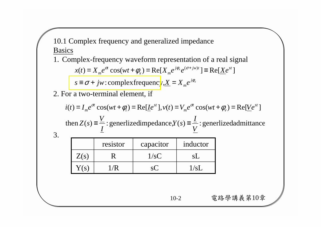
10.1 Complex frequency and generalized impedance Basics1. Complex-frequency waveform representation of a real signal
x
x
jm
sttjwjmx
tm
eXXjws
eXeeXwteXtxφ
σφσ
σφ
=+≡
≡=+= +
frequency,complex :
]Re[]Re[)cos()( )(
3. admittance generlized:)(impedance, generlized:)(then
]Re[)cos()(],Re[)cos()(
VIsY
IVsZ
eVwteVtveIwteIti stv
tm
sti
tm
≡≡
=+==+= φφ σσ
2. For a two-terminal element, if
1/sLsC1/RY(s)sL1/sCRZ(s)
inductorcapacitorresistor

電路學講義第10章10-3
4. s-domain diagram
5. Phasor representation is a special form as s=jw, σ=0.Frequency-diagram is a special case of s-domain diagram with s=jw,σ=0.
6. Application: more general form to analyze the circuit forced response. Chapter 13 “Laplace transform” will be intoduced to analyze the complete response (zero-input response and forced response).
電路學講義第10章10-4
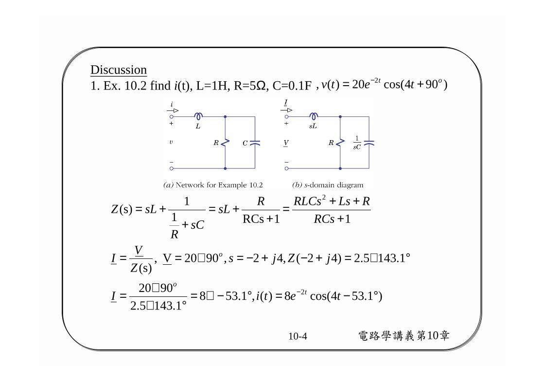
Discussion1. Ex. 10.2 find i(t), L=1H, R=5Ω, C=0.1F )904cos(20)( , 2 ot tetv += −
)1.534cos(8)(,1.5381.1435.2
9020
1.1435.2)42(,42,9020V ,(s)
1
1RCs1
1(s)
2
2
°−=°−∠=°∠
∠=
°∠=+−+−=∠==
+++=
++=
++=
− tetiI
jZjsZVI
RCsRLsRLCsRsL
sCR
sLZ
to
o
電路學講義第10章10-5
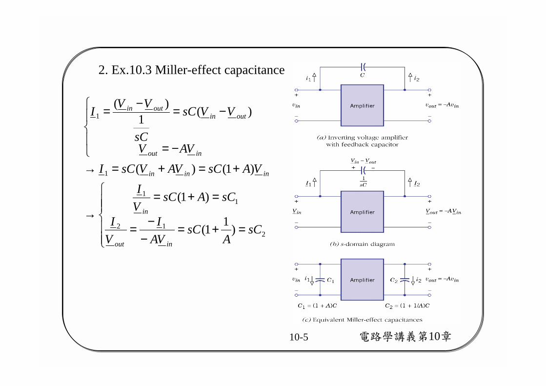
2. Ex.10.3 Miller-effect capacitance
=+=−
−=
=+=→
+=+=→
−=
−=−=
212
11
1
1
)11(
)1(
)1()(
)(1)(
sCA
sCVAI
VI
sCAsCVI
VAsCVAVsCIVAV
VVsC
sC
VVI
inout
in
ininin
inout
outinoutin

電路學講義第10章10-6
3. Ex. 10.4 Generalized impedance converter, find Zin(s)
resistor negativedependent -frequency
)(1)(,1,1inductor capacitor elements, resistive ,,,
,
)()3(,)4(
)5...(
)4...(
)3...(
)2...(
op 2nd for the
)1...( op1st for the
222242153
25314
42
531
531
42
5
31
42
31
42)5(),2(
34
31
2
3
1
21)1(
33
43
5
21
1
=−==→=====
→=⇒
=−−
=→−=−=→
=−+
=−=
−=
−=
=
+=
wRRCw
jwZRCs
ZRZZZsC
ZZ
ZZZZZZ
ZZZZZZ
VZZZ
ZZZ
VZZZZVV
IVZZZZVIZVV
VZZ
ZZ
VVZ
ZZ
ZVVI
ZVVI
ZVVI
VV
VZZ
ZV
eqinin
in
in
in
ininin
inininbc
in
ininba
cb
cinin
bin
ain
電路學講義第10章10-7
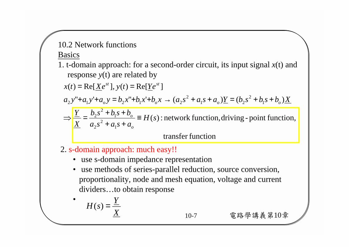
10.2 Network functionsBasics1. t-domain approach: for a second-order circuit, its input signal x(t) and
response y(t) are related by
functiontransfer
function,point -drivingfunction,network :)(
)()('"'"]Re[)(],Re[)(
12
2
12
2
12
212
21212
sHasasabsbsb
XY
XbsbsbYasasaxbxbxbyayayaeYtyeXtx
o
o
oooo
stst
≡++++=⇒
++=++→++=++==
2. s-domain approach: much easy!!• use s-domain impedance representation• use methods of series-parallel reduction, source conversion,
proportionality, node and mesh equation, voltage and current dividers…to obtain response
•XYsH =)(
電路學講義第10章10-8
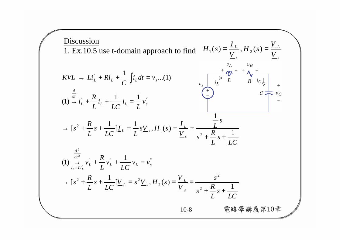
Discussion1. Ex.10.5 use t-domain approach to find
LCs
LRs
sVVsHVsV
LCs
LRs
vvLC
vLRv
LCs
LRs
sL
VIsHVs
LI
LCs
LRs
vL
iLC
iLRi
vdtiC
RiLiKVL
s
LsL
sLLL
dtd
Liv
s
LsL
sLLL
dtd
sLLL
LL
1)(,]1[
1)1(
1
1
)(,1]1[
11)1(
)1...(1
2
2
222
"'"
21
2
''"
'
2
2
'
++===++→
=++→
++===++→
=++→
=++→
=
∫
s
L
s
L
VVsH
VIsH == )(,)( 21
電路學講義第10章10-9
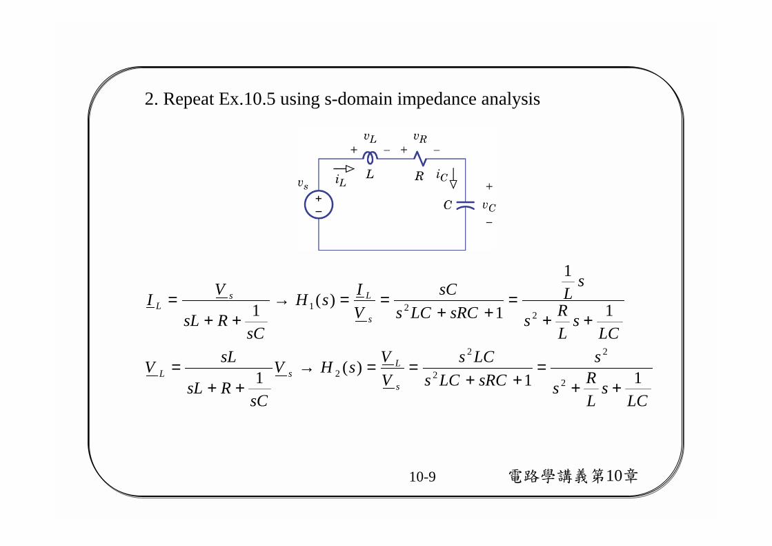
2. Repeat Ex.10.5 using s-domain impedance analysis
LCs
LRs
ssRCLCs
LCsVVsHV
sCRsL
sLV
LCs
LRs
sL
sRCLCssC
VIsH
sCRsL
VI
s
LsL
s
LsL
11)(1
1
1
1)(1
2
2
2
2
2
221
++=
++==→
++=
++=
++==→
++=
電路學講義第10章10-10
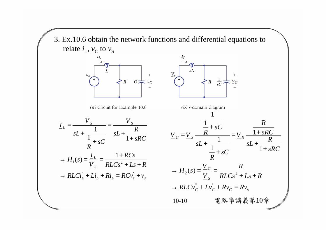
3. Ex.10.6 obtain the network functions and differential equations torelate iL, vC to vS
ssLLL
S
L
SSL
vRCvRiLiRLCiRLsRLCs
RCsVIsH
sRCRsL
V
sCR
sL
VI
+=++→
+++==→
++
=
++
=
''"
211)(
111
sCCC
S
C
SSC
RvRvLvRLCvRLsRLCs
RVVsH
sRCRsL
sRCR
V
sCR
sL
sCRVV
=++→
++==→
++
+=
++
+=
'"
22 )(
1
1
11
11

電路學講義第10章10-11
4. Ex.10.7 obtain the network functions to relate v1, v2, v3 to vin
[ ]
[ ]
[ ] [ ][ ]
[ ]
ininin
in
in
in
in
in
in
S
SSSout
s
Fout
VV
VV
VV
VGVsC
VVV
GsCGsCGGsC
GsCGsC
VVVG
VGVsC
VGVGVsC
I
IGIIVV
GsCGsCGGsCsCGsC
Y
IVYY-
vvR
RRv
RRR
v
321
3
2
1
3
2
13
~
~~
333
,,
0)(20
)(0)(2
000000
200
00
2
,equation constraint
220022
analysismatrix node
)1(
⇒
=
+−−−+
+−+
+
=
+=
+
==
+−−−+−+
=
=
=+−
=+
=
µ
µµ
µ
µµ
µ
µµ
µ
µ
電路學講義第10章10-12
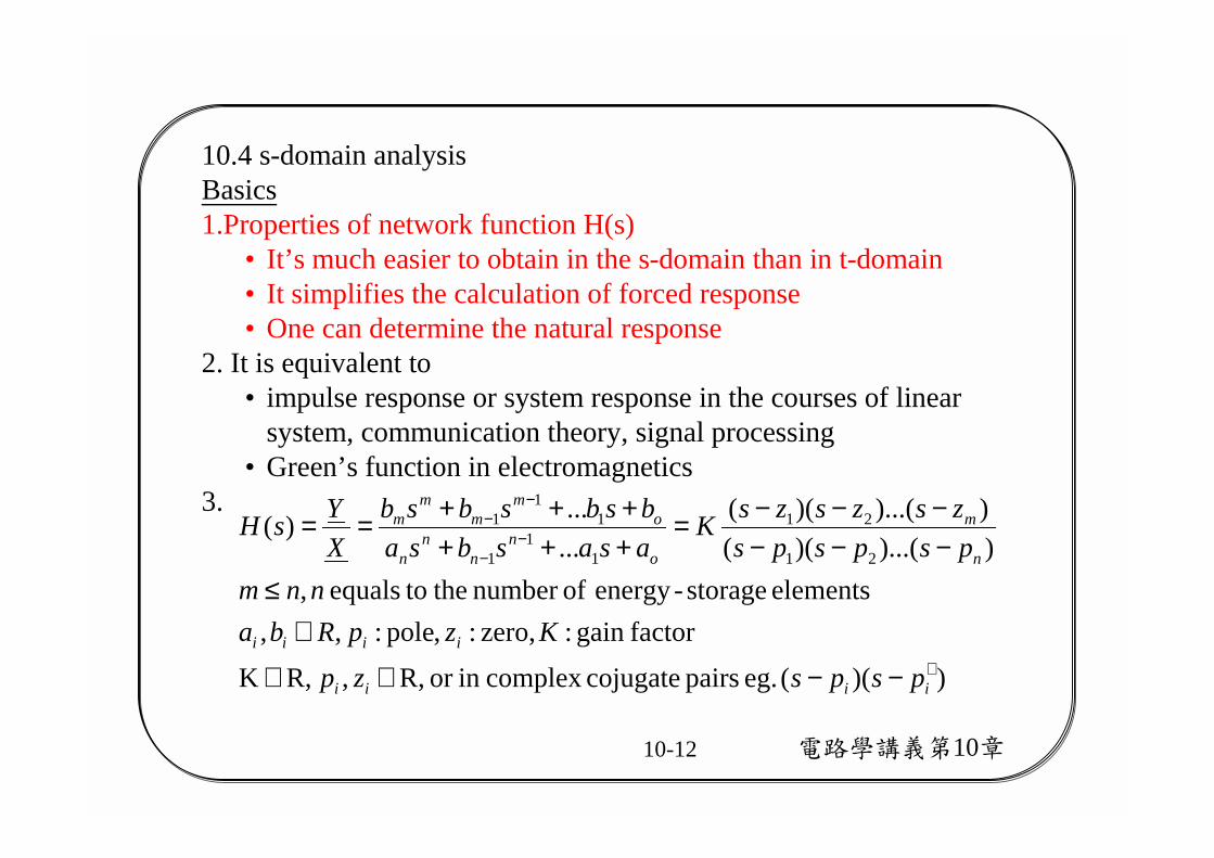
10.4 s-domain analysisBasics1.Properties of network function H(s)
• It’s much easier to obtain in the s-domain than in t-domain• It simplifies the calculation of forced response• One can determine the natural response
2. It is equivalent to• impulse response or system response in the courses of linear
system, communication theory, signal processing• Green’s function in electromagnetics
3.
))(( eg. pairs cojugatecomplex in or R,, R,K
factorgain :zero,:,pole:,,elements storage-energy ofnumber the toequals ,
))...()(())...()((
......)(
21
21
11
1
11
1
∗
−−
−−
−−∈∈
∈≤
−−−−−−=
++++++==
iiii
iiii
n
m
on
nn
n
om
mm
m
pspszpKzpRba
nnmpspspszszszsK
asasbsabsbsbsb
XYsH

電路學講義第10章10-13
4. A network function is completely defined by gain factor, zeros and poles.
5. Pole and zero are displayed in s-plane s=σ+jw as pole-zero pattern
)]74()][74([)10()(
jsjsssKsH
−−−+−−+=
poles are in the LHP(left half plane)

電路學講義第10章10-14
6. Forced response calculation• given H(s)• if • then
]Re[)( tsoeXtx =
)...]()([)...]()([)(
......
)(
)()()(
])...)(()...)((Re[])(Re[]Re[)(
21
21
21
21
21
21
pspszszsKsH
pspszszs
KsH
sHsHsH
eXpspszszsKeXsHeYty
oo
ooo
oo
ooo
ooo
ts
oo
ootso
ts ooo
−∠+−∠−−∠+−∠+∠=∠
−−−−
=
∠=−−−−===

電路學講義第10章10-15
7. Natural response calculation• given
• then )()(
)()(
))(())(()(
21212
21212
21
21
sPsZK
ppsppszzszzsK
pspszszsK
XYsH =
++−++−=
−−−−==
mode. TEM e.g. netics,electromagin used widely is mode termTheresponse natural theof mode"" one:)cos(2
...)cos(2...)(
,then ,0, e.g.response natural scircuit' of valuessticcharacterior es,eigen valu are poles
)()( polynomial sticcharacteri
0)(]')("[')("
1
21212
21'
21"
21212121
iit
i
iit
itjwt
itjwt
iN
iiiiiii
NNN
AtweA
AtweAeAeAtyjwpwjwp
ppsppssPyppyppy
xzzxzzxKyppyppy
i
iiiii
∠+
+∠+=++=
−=≠+=→→
++−=→
=++−→
++−=++−
−∗+
+
σ
σσσ
σσ
電路學講義第10章10-16
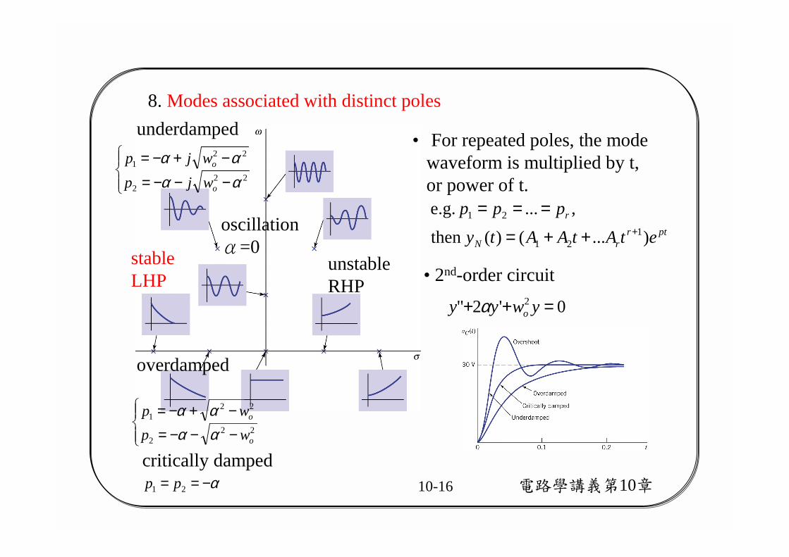
8. Modes associated with distinct poles
• For repeated poles, the mode waveform is multiplied by t, or power of t.
ptrrN
r
etAtAAtyppp
)...()(then ,... e.g.
121
21+++=
===oscillationα=0stable
LHPunstableRHP
overdamped
−−−=−+−=
222
221
o
o
wpwp
αααα
underdamped
−−−=−+−=
222
221
αααα
o
o
wjpwjp
• 2nd-order circuit
0'2" 2 =++ ywyy oα
critically dampedα−== 21 pp

電路學講義第10章10-17
9. A network is stable when all of its poles are in the left half of the s-plane, irrespective of pole-zero cancellation.
0 as ,0)(0LHP in the →→=⇒<→+= + teAtyjwp tjwtiNiiii
iiσσσ
10. Any network that contains resistance and no controlled sources is stable.
電路學講義第10章10-18
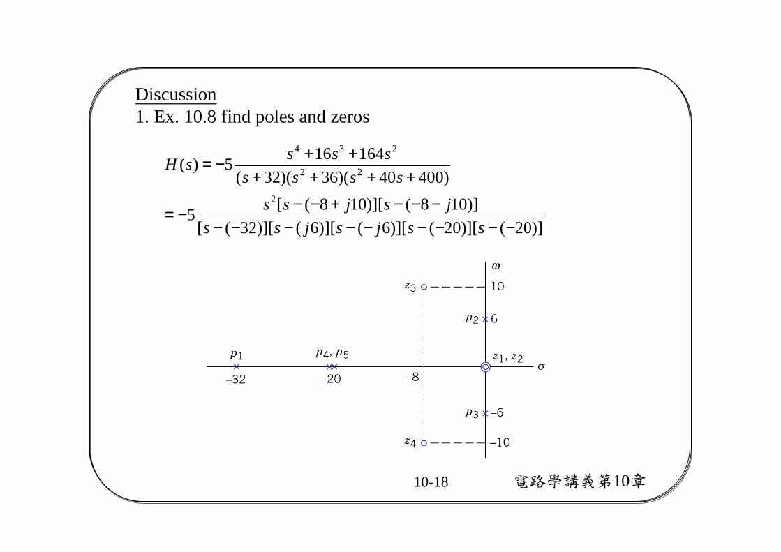
Discussion1. Ex. 10.8 find poles and zeros
)]20()][20()][6()][6()][32([)]108()][108([5
)40040)(36)(32(164165)(
2
22
234
−−−−−−−−−−−−+−−−=
++++++−=
ssjsjssjsjss
ssssssssH

電路學講義第10章10-19
2. Ex. 10.9 given H(s) and x(t), find forced response
°−∠==→
°−∠=−−−+−−
−=
===−−−+−−
−=++
−=
+−−
5.1087.23)(
5.10837.2)]36()][36([
6)(
]10Re[]Re[3cos10)()]36()][36([
64512
6)(
)34(4
2
XsHYjsjs
ssH
eeXtetxjsjs
sssssH
o
oo
oo
tjtst o
電路學講義第10章10-20
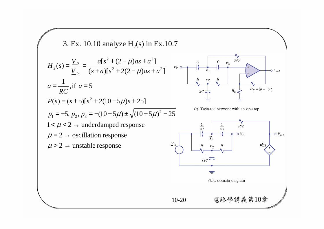
3. Ex. 10.10 analyze H2(s) in Ex.10.7
response unstable2responsen oscillatio2
response dunderdampe2125)510()510(,,5
]25)510(2)[5()(
5 if,1])2(2)[(
])2([)(
2321
2
22
222
2
→>→=
→<<−−±−−=−=
+−++=
==
+−+++−+==
µµ
µµµ
µ
µµ
ppp
ssssP
aRC
a
aassasaassa
VVsH
in
電路學講義第10章10-21
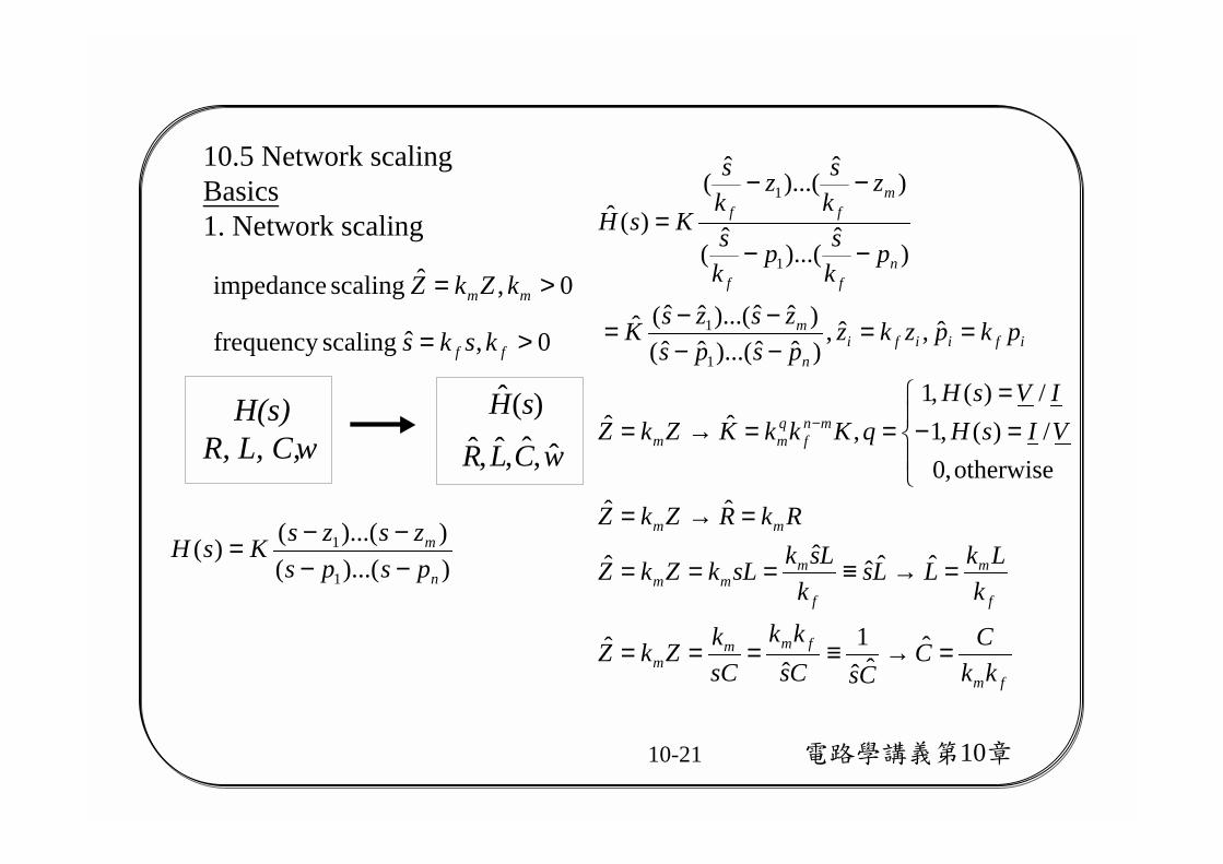
10.5 Network scalingBasics1. Network scaling
fm
fmmm
f
m
f
mmm
mm
mnf
qmm
ifiifin
m
nff
mff
kkCC
CsCskk
sCkZkZ
kLkLLs
kLsksLkZkZ
RkRZkZ
VIsHIVsH
qKkkKZkZ
pkpzkzpspszszsK
pksp
ks
zksz
ks
KsH
=→≡===
=→≡===
=→=
=−=
==→=
==−−−−=
−−
−−=
−
ˆˆˆ
1ˆ
ˆ
ˆˆˆˆˆ
ˆˆotherwise,0
/)(,1/)(,1
,ˆˆ
ˆ,ˆ,)ˆˆ)...(ˆˆ()ˆˆ)...(ˆˆ(ˆ
)ˆ
)...(ˆ
(
)ˆ
)...(ˆ
()(ˆ
1
1
1
1
H(s)R, L, C, w wCLR
sH
ˆ,ˆ,ˆ,ˆ)(ˆ
0,ˆ scalingfrequency >= ff ksks
0,ˆ scaling impedance >= mm kZkZ
))...(())...(()(
1
1
n
m
pspszszsKsH
−−−−=
電路學講義第10章10-22
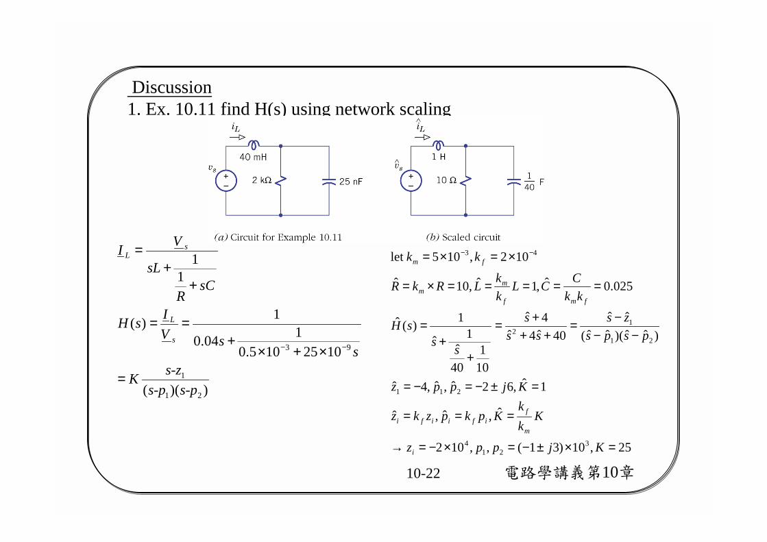
Discussion1. Ex. 10.11 find H(s) using network scaling
))((
1025105.0104.0
1)(
11
21
1
93
s-ps-ps-zK
ssV
IsH
sCR
sL
VI
s
L
sL
=
×+×+
==
++
=
−−
25,10)31(,,102
ˆ,ˆ,ˆ
1ˆ,62ˆ,ˆ,4ˆ
)ˆˆ)(ˆˆ(ˆˆ
40ˆ4ˆ4ˆ
101
40ˆ
1ˆ
1)(ˆ
025.0ˆ,1ˆ,10ˆ
102,105let
321
4
211
21
12
43
=×±−=×−=→
===
=±−=−=
−−−=
+++=
++
=
=====×=
×=×= −−
Kjppz
Kkk
Kpkpzkz
Kjppz
pspszs
sss
sssH
kkCCL
kkLRkR
kk
i
m
fifiifi
fmf
mm
fm