Chapter 10 · Chapter 10 Abiotic filtration ... advantages, disadvantages and caveats associated...
18
85 Chapter 10 Abiotic filtration methods for live coral systems in public aquaria RICHARD TERRELL, JR. 1 , RICHARD KLOBUCHAR, JR. 2 AND CARRIE PRATT 3 1 Pittsburgh Zoo & PPG Aquarium, One Wild Place, Pittsburgh, PA 15206, USA [email protected] 2 University of Hawaii - Waikiki Aquarium, 2777 Kalakaua Avenue, Honolulu, HI 96815, USA [email protected] 3 Columbus Zoo and Aquarium, 9990 Riverside Drive, Powell, Ohio 43065, USA [email protected] ABSTRACT Over recent decades, advances in life support systems (LSS) for captive corals have increased public aquariums’ ability to more closely mimic water quality conditions found on coral reefs. This, in turn, has allowed these institutions to keep, exhibit and reproduce an increasing diversity of coral species. We will discuss abiotic LSS in terms of mechanical and chemical filtration. Mechanical filtration will focus on such methods as filter floss, cartridge filters, rapid sand filters and bag filters. Examples of chemical filtration included are ozone, ultraviolet sterilizers, carbon and other adsorptive media and ion exchange resins. Perhaps the most significant development in abiotic LSS for living reef systems is the use of foam fractionation. This unique life support element functions as both chemical and mechanical filtration. We will discuss the advantages, disadvantages and caveats of each filtration device or medium as they relate to the husbandry of live corals in public aquaria. The authors also conducted a survey of public aquaria that exhibit live corals to ascertain the prevalence of different abiotic life support components in the industry. Foam fractionation was used in all but one of the responding institutions. The second most prevalent filtration device was activated carbon, with well over half the respondents using it either intermittently or continuously. INTRODUCTION The success of keeping live corals in public aquaria has advanced significantly in recent decades. Much of this can be directly related to improvements in filtration methods and an increased understanding of the interactions between water quality and captive coral health. In this chapter we will summarize the function, advantages, disadvantages and caveats associated with the different filtration methods employed by public aquariums in caring for live corals.Filtration can generally be broken into three functionalities: mechanical, chemical and biological (Moe, 1989). While some biological filtration devices perform mechanical or chemical filtration functions as part of their normal functionality, in this paper we will focus on non-living, or abiotic, mechanical and chemical filtration devices. The authors conducted a brief survey (see Appendix 1) of public aquaria throughout the world to determine which abiotic filtration devices were in use in public institutions at this time. The results of this survey are summarized in Table 1. We will further limit our discussion to those devices used in public aquaria as determined by this survey. MECHANICAL FILTRATION Mechanical filtration is defined by Spotte (1970) as “the physical separation and concentration of suspended particulate matter from circulating water. It is accomplished by passing the water through suitable substrata or septa that trap the particles.” Its functions in a closed marine Advances in Coral Husbandry in Public Aquariums. Public Aquarium Husbandry Series, vol. 2. R.J. Leewis and M. Janse (eds.), pp. 85-102 © 2008 Burgers’ Zoo, Arnhem, the Netherlands.
Transcript of Chapter 10 · Chapter 10 Abiotic filtration ... advantages, disadvantages and caveats associated...

85
Chapter 10
Abiotic filtration methods for live coral systemsin public aquaria
RichaRd TeRRell, JR.1, RichaRd KlobuchaR, JR.2 and caRRie PRaTT3
1 Pittsburgh Zoo & PPG Aquarium, One Wild Place, Pittsburgh, PA 15206, USA [email protected]
2 University of Hawaii - Waikiki Aquarium, 2777 Kalakaua Avenue, Honolulu,HI 96815, USA
[email protected] 3 Columbus Zoo and Aquarium, 9990 Riverside Drive, Powell, Ohio 43065, USA
AbstrACtOver recent decades, advances in life support systems (LSS) for captive corals have increased public aquariums’ ability to more closely mimic water quality conditions found on coral reefs. This, in turn, has allowed these institutions to keep, exhibit and reproduce an increasing diversity of coral species. We will discuss abiotic LSS in terms of mechanical and chemical filtration. Mechanical filtration will focus on such methods as filter floss, cartridge filters, rapid sand filters and bag filters. Examples of chemical filtration included are ozone, ultraviolet sterilizers, carbon and other adsorptive media and ion exchange resins. Perhaps the most significant development in abiotic LSS for living reef systems is the use of foam fractionation. This unique life support element functions as both chemical and mechanical filtration. We will discuss the advantages, disadvantages and caveats of each filtration device or medium as they relate to the husbandry of live corals in public aquaria. The authors also conducted a survey of public aquaria that exhibit live corals to ascertain the prevalence of different abiotic life support components in the industry. Foam fractionation was used in all but one of the responding institutions. The second most prevalent filtration device was activated carbon, with well over half the respondents using it either intermittently or continuously.
IntroduCtIon
The success of keeping live corals in public aquaria has advanced significantly in recent decades. Much of this can be directly related to improvements in filtration methods and an increased understanding of the interactions between water quality and captive coral health. In this chapter we will summarize the function, advantages, disadvantages and caveats associated with the different filtration methods employed by public aquariums in caring for live corals.Filtration can generally be broken into three functionalities: mechanical, chemical and biological (Moe, 1989). While some biological filtration devices perform mechanical or chemical filtration functions as part of their normal functionality, in this paper we will focus on non-living, or abiotic, mechanical and chemical filtration devices. The authors
conducted a brief survey (see Appendix 1) of public aquaria throughout the world to determine which abiotic filtration devices were in use in public institutions at this time. The results of this survey are summarized in Table 1. We will further limit our discussion to those devices used in public aquaria as determined by this survey.
MeChAnICAl FIltrAtIon
Mechanical filtration is defined by Spotte (1970) as “the physical separation and concentration of suspended particulate matter from circulating water. It is accomplished by passing the water through suitable substrata or septa that trapthe particles.” Its functions in a closed marine
Advances in Coral Husbandry in Public Aquariums. Public Aquarium Husbandry Series, vol. 2. R.J. Leewis and M. Janse (eds.), pp. 85-102© 2008 Burgers’ Zoo, Arnhem, the Netherlands.
86
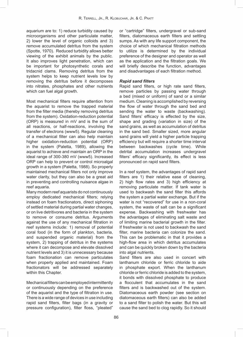
aquarium are to: 1) reduce turbidity caused by microorganisms and other particulate matter, 2) lower the level of organic colloids and 3) remove accumulated detritus from the system (Spotte, 1970). Reduced turbidity allows better viewing of the exhibit animals by the public. It also improves light penetration, which can be important for photosynthetic corals and tridacnid clams. Removing detritus from the system helps to keep nutrient levels low by removing the detritus before it decomposes into nitrates, phosphates and other nutrients which can fuel algal growth.
Most mechanical filters require attention from the aquarist to remove the trapped material from the filter media (thereby removing detritus from the system). Oxidation-reduction potential (ORP) is measured in mV and is the sum of all reactions, or half-reactions, involving the transfer of electrons (www5). Regular cleaning of a mechanical filter can also help maintain higher oxidation-reduction potential (ORP) in the system (Paletta, 1989), allowing the aquarist to achieve and maintain an ORP in the ideal range of 300-380 mV (www5). Increased ORP can help to prevent or control microalgal growth in a system (Paletta, 1988). So properly maintained mechanical filters not only improve water clarity, but they can also be a great aid in preventing and controlling nuisance algae in reef aquaria.Many modern reef aquarists do not continuously employ dedicated mechanical filters; relying instead on foam fractionators, direct siphoning of settled material during partial water changes, or on live detritivores and bacteria in the system to remove or consume detritus. Arguments against the use of any mechanical filtration in reef systems include: 1) removal of potential coral food (in the form of plankton, bacteria, and suspended organic material) from the system, 2) trapping of detritus in the systems where it can decompose and elevate dissolved nutrient levels and 3) it is unnecessary because foam fractionation can remove particulates when properly applied and maintained. Foam fractionators will be addressed separately within this Chapter.
Mechanical filters can be employed intermittently or continuously depending on the preference of the aquarist and the type of filtration in use. There is a wide range of devices in use including rapid sand filters, filter bags (in a gravity or pressure configuration), filter floss, “pleated”
or “cartridge” filters, undergravel or sub-sand filters, diatomaceous earth filters and settling sumps. As with any life support component, the choice of which mechanical filtration methods to utilize is determined by the individual preference of the designer and operator as well as the application and the filtration goals. We will briefly describe the function, advantages and disadvantages of each filtration method.
Rapid sand filtersRapid sand filters, or high rate sand filters, remove particles by passing water through a bed (mixed or uniform) of sand or a similar medium. Cleaning is accomplished by reversing the flow of water through the sand bed and sending the water to waste (backwashing). Sand filters’ efficacy is effected by the size, shape and grading (variation in size) of the sand grains, as well as accumulation of detritus in the sand bed. Smaller sized, more angular sand grains will yield a higher particle trapping efficiency but will require a shorter time interval between backwashes (cycle time). While detrital accumulation increases undergravel filters’ efficacy significantly, its effect is less pronounced on rapid sand filters.
In a reef system, the advantages of rapid sand filters are 1) their relative ease of cleaning, 2) high flow rates and 3) high efficiency at removing particulate matter. If tank water is used to backwash the sand filter this affords the system a partial water exchange. But if the water is not “recovered” for use in a non-coral system, the waste of salt can be a significant expense. Backwashing with freshwater has the advantages of eliminating salt waste and of limiting marine bacterial growth in the filter. If freshwater is not used to backwash the sand filter, marine bacteria can colonize the sand. This can be problematic in that it provides a high-flow area in which detritus accumulates and can be quickly broken down by the bacteria into algal nutrients.Sand filters are also used in concert with lanthanum chloride or ferric chloride to aide in phosphate export. When the lanthanum chloride or ferric chloride is added to the system, it bonds with dissolved phosphate to produce a flocculent that accumulates in the sand filters and is backwashed out of the system. Diatomaceous earth powder (see section on diatomaceous earth filters) can also be added to a sand filter to polish the water. But this will cause the sand bed to clog rapidly. So it should
R. TeRRell, JR., R. KlobuchaR, JR. & c. PRaTT

87
chaPTeR 10: abioTic filTRaTion meThods foR live coRal sysTems in Public aquaRia
be followed shortly by a backwash.
Sand filters are used more commonly on large (>15,000 L) live reef exhibits than smaller exhibits. This is largely a function of the volume of particulates in such a system, versus a smaller reef system. But the flow required to operate a rapid sand filter is also a possible explanation. Smaller systems may not require, or be able to tolerate, high enough flow rates to allow proper function of a rapid sand filter.
Activated Filtration MediaTM (Dryden Aqua, Ltd., Edinbugh, Scotland)Activated Filtration Media, or AFM, is an alternative media for sand filters. It is an activated form of glass. The manufacturer claims that its benefits include:
“Increases water clarity by removal of 1) colloidal matter Remove at least 50% more solids from 2) the water, including bacteria, algae and protozoa Reduce the amount of nitrate produce by 3) reducing the mineralization of protein High surface negative zeta potential 4) attract +ve charges organic molecules High surface oxidation potential, helps 5) to crack organics, just like ozone and UV-C systems Use only ½ the amount of back-wash 6) water Removes colour by catalytically 7) cracking organic molecules, due to surface oxidation potential Adsorbs micron and sub-micron 8) particles including organic molecules (and colour), 100 % released on back-wash into waste water AFM will not generate solids & 9) bacteria, or periodically dump solids & bacteria into the water. Sand filters will periodically discharge into the product water, see report on drinking water treatment Will minimise phosphates, especially 10) when combined with NoPhos due to high surface zeta potentia “ (www1)
Tony McEwan reported on use of AFM in the incoming raw water system at The Scientific Center in Kuwait. He saw increased water clarity, reduced water color, decreased backwash time, lowered ozone usage, and no coagulation of the medium (McEwan, EUAC, 2005). AFM has
been used on live coral systems as well. One institution removed it from their system as a precaution when they read that AFM removes heavy metals (Janse, pers. com.).
Possible disadvantagesAFM is very expensive, when compared to silica sand (as much as five times the cost). But its advantages often allow an institution to recover the additional costs in as little as sixteen months (McEwan, EUAC jaar opzoekn). This medium requires further research and testing before it can be viewed as a safe and effective option for use on closed system live coral exhibits. Potential research topics could include: trace metal removal by AFM in closed system aquaria, potential for erosion and release of medium into the exhibit system, long-term effects of AFM on live coral water quality parameters, and relative growth of coral in systems using AFM (compared to traditional sand filter sand).
Filter floss and gravity-fed filter bagsPolyester filter floss and polypropylene bags are often used between an overflow or surface skimmer and a pump or sump to trap particulates. Efficacy will be influenced by the pore size of the material and detrital accumulation. In general, finer pore size material costs more than coarser material. Because they are in line from the surface skimmer to the pump or a sump, these filter media do not put back-pressure on pumps like a rapid sand filter, cartridge filter or pressurized bag filter can. They are relatively easy to add to or remove from the system. Cleaning to remove the trapped debris can be accomplished with a hose or in a washing machine. Filter floss does not generally last through many cleanings. Depending on the bio-load of the system, both of these media can clog quickly, necessitating cleaning or changing frequently. They are used both intermittently and continuously in public aquarium applications.
Settling sumpsA settling sump is simply a container, external to the main aquarium, where water flow is slowed down, allowing suspended solids to settle on the bottom of the container. If a bulkhead and valve are placed low on this sump, the accumulated solids can then be drained off to waste. Alternatively, the accumulated debris can be manually siphoned out or pumpedout to waste. This can be an effective means
88
of removing solids from the main system. Because the removal of the solids from the sump potentially requires waste of some system water, it can be costly over time. But this also affords a chance for partial water changes. Sumps can also occupy a large footprint if a long or wide and shallow sump is used. A tall sump saves footprint space, but makes access to the bottom of the sump more difficult.
Sumps offer a myriad of other advantages including, but not limited to: 1) a convenient place to add other filtration components (mechanical, chemical, biological, or others), 2) holding space for fish from the main system, 3) a place to add supplements or additives away from the inhabitants of the main tank. All of these can be compatible with the use of the sump as a settling area, provided they do not increase water flow in, or through, the sump. When they are employed on public aquarium coral tanks, sumps are generally a permanent and continuous part of the LSS.
Cartridge (pleated) filters and pressurized bag filtersBoth pleated filters and pressurized bag filters consist of a closed cylinder except for the inlet and outlet pipes. Water is forced through the cylinder and the appropriate filter medium by the pump. There is usually no bypass of water within the filter such that any water, or debris, entering the filter must pass through the filter media (or be trapped by it). In the case of cartridge filters, the medium is usually a pleated polyester fiber cloth over a rigid core cartridge. The same filter bags (or socks) that were discussed earlier function as the medium in pressurized bag filters. In both cases the media is usually rated at a given pore size, usually in microns. So efficacy can be related to this pore size, detrital loading and surface area of the filter cartridge or bag. Smaller pore sizes are more efficient at removing particles from the system, but they require more frequent cleaning by the aquarist. Both cartridges and bags can be cleaned with a pressure nozzle on a hose and a chlorine bleach soak. While the filter bags can be machine-washed, the pleated cartridges cannot. Both types of media have a limited useful life and must eventually be replaced.
In heavy load situations, these filters’ efficacy means that they will clog very quickly. This
can be good in that the debris can then be removed from the system. But the lack of any bypass within the filter itself means that clogged media will dramatically reduce flow and put backpressure on the pump if there is no bypass line plumbed into the system. The high efficiency of these types of filters and the resulting tendency to clog quickly means that they are more suited to intermittent use (e.g., following a major scrubbing of the rockwork) in a live coral system with any significant bioload, unless the aquarist is committed to cleaning and replacing filters frequently.
Diatomaceous earth filtersDiatomaceous earth, or DE, filters are similar to the cartridge filters in that the filter element is made up of a supportive core covered by a fibrous polypropylene or polyester cloth filter sleeve. What sets them apart is that the filter sleeve is then coated with a layer of graded skeletal remains of diatoms (DE powder) called the filter cake. The filter cake is held in place by vacuum or pressure. It prevents debris from permanently clogging the filter element and increases the efficiency of the filter element. For permanently installed DE filters, it is often necessary to install a “precoat pot” to facilitate pre-coating the filter element with fresh DE powder after cleaning. Efficacy of DE filters can be affected by the precoat (the new layer of DE after cleaning the filter element), the surface area of the filter element, and cleaning of the filter element (Spotte, 1970). Because diatom tests are composed primarily of silicate, extended use of a DE filter could theoretically elevate silicate levels in the system, causing unsightly blooms of live diatoms. DE filters are highly efficient, meaning that they are very good at removing even very small particles in a relatively short time. But this also means that they clog very quickly. So they are often used intermittently to “polish” the system water to the point that it sparkles, often immediately after events that cloud the water like stirring sand or scrubbing rockwork.
Undergravel or sub-sand filtersUndergravel filters (UGF’s) consist of a perforated plate on the bottom of the tank covered by gravel or sand. Water is moved through the gravel where detritus is trapped in two ways: 1) physically in the interstices of the gravel bed and 2) electrostatically to the gravel surface (Spotte, 1970). Normal water flow for a UGF filter is down through the gravel,
R. TeRRell, JR., R. KlobuchaR, JR. & c. PRaTT

89
chaPTeR 10: abioTic filTRaTion meThods foR live coRal sysTems in Public aquaRia
through the perforated plate and up a lift tube back to the main tank.
In “reverse flow undergravel filters” the water is pumped down under the plate and flows up through the gravel. If this water is pre-filtered mechanically in some way before being pumped under the filter plate, it leaves little detritus under the gravel bed (avoiding this disadvantage of normal flow UGF’s) and helps to avoid detritus from settling in the substrate. If raw tank water is pumped under the filter plate, it can deposit large amounts of detritus there, where it is difficult for the aquarist to remove it from the system.
A perceived disadvantage of normal and reverse-flow UGF’s is that they act as a biofilter where detritus is efficiently broken down into nitrate and phosphate, thereby feeding nuisance algae. At the same time, they require the aquarist to siphon clean the substrate to remove the trapped detritus. This can remove large numbers of detritivores from the system along with the detritus, thereby removing a biological detritus sink. According to our survey (Table 1), these filters are rarely used in today’s public aquarium live coral aquaria.
CheMICAl FIltrAtIon
In order to understand the relevance of chemical filtration in coral, clam, and other invertebrate applications, it is helpful to have an understanding of what chemical filtration is, why it is used, and how it works in the first place. Chemical filtration can be defined as the removal of compounds from a solution through the processes of absorption, adsorption, and/or ion-exchange. Moe (1989) further simplifies this definition by stating “chemical filtration is actually mechanical filtration on a molecular basis.” Understanding which compounds are being removed from the solution is equally as important, as different filtration techniques remove different compounds. Dissolved compounds accumulate through various biological processes. And the accumulation of these dissolved compounds can have serious effects on the inhabitants within the system. Increases in dissolved carbon-containing compounds, otherwise known as dissolved organic compounds (DOC), such as amino acids, carbohydrates, fats, proteins, various
organic acids, and many others may effect growth, disease resistance, and the metabolic stress rates of our animals (Delbeek and Sprung, 2005). When used properly with other forms of mechanical and biological filtration, which serve to remove or break down particulate organic compounds (POC), chemical filtration can combat the negative effects of DOC on system inhabitants by removing them before they accumulate; thereby reducing the concentrations of total organic compounds (TOC), lightening filter loads, reducing nitrate levels, and increasing water clarity by removing the organic compounds responsible for the yellowing of system water.
As mentioned earlier, three processes make up chemical filtration, and most good chemical filter media use some aspect of each one to remove as many different dissolved organic compounds or other specific compounds, such as toxic heavy metals, as possible. The absorption property of chemical filtration media draws a fine line between mechanical and chemical filtration. Instead of collecting large suspended particles from the system water, media that use absorption collect and “trap” tiny individual molecules within the porous, channeling maze that runs throughout each bead, fiber, or granule of media. Unfortunately, there are no attractive charges or bonds to keep these molecules secured in place, and these media can “fill” or become exhausted. When this happens the trapped molecules can find their way back into the system water.
Media such as ion-exchange resins use the charge of an ionized molecule to bond to their oppositely charged surfaces. The benefit to this type of media is that a chemical bond is formed when the ionized molecules touch an oppositely charged surface and they become firmly attached to that surface. This is great in freshwater applications where there are few anions and cations. But in seawater applications, these media can become quickly exhausted as they are bound up by the high concentrations of organic molecules and cations, such as sodium. Fortunately, more ion-exchange resins are being manufactured for use in marine systems using different industrial processes and specific impurities that affect the ion-exchange characteristics of the resin.Adsorption in aquaria occurs when molecules are physically bound to the surface of a filter

90
media or substrate. Adsorption can occur as water to solid adsorption and/or water to gas adsorption. In either case, bonds are formed when complex, organic, polarized molecules or, polarized molecules with hydrophilic and hydrophobic ends, are attracted and attached to a polar media and then held together by strong or weak charges. Permanent bonds are formed when strong attractive charges are involved, while bonds between weak attractive charges can be broken or reversed in a process known as desorption. An example of desorption would be the release of some organic molecules from a particular surface due to a change in pH of a certain solution (Moe, 1989).As in most things that have advantages to them, there always seems to be some drawbacks as well. Concerns over the release of previously absorbed substances, depletion of beneficial trace elements, leaching of chemicals such as phosphate and silicate, reduction in pH and alkalinities, and rapid die-off caused by sudden water clarity changes or nutrient level drop-offs make up just a few of the more widely discussed caveats that aquarists and hobbyists alike have had to deal with over the years. To help combat these issues, some aquarists and hobbyists have chosen to avoid using chemical filtration methods as much as possible, while others continue to employ continuous or intermittent uses of their various types of chemical filtration. The debate over continuous versus intermittent use, or even any chemical filtration use at all, will undoubtedly continue to roar on for years to come as each system has its own needs and varies from the next.
No chapter on chemical filtration would be complete without the discussion of Granular Activated Carbon (GAC). While GAC is perhaps the most commonly used type of chemical filtration media, several other types of media are beginning to be used with more regularity. Phosphate adsorption media used for the removal of inorganic phosphate (orthophosphate), orthophosphate precipitants such as lanthanum chloride (LaCl3.5H2O), ion-exchangers such as zeolites, synthetic ion-exchange resins, molecular adsorption filters/pads, and synthetic adsorbent polymer resins are just some of the different media that are currently being used in coral and invertebrate systems. As with the previous section on mechanical filtration, we will briefly discuss the function, advantages, and disadvantages of each filtration method or medium.
CarbonCarbon goes by many different names. Coal, aquarium charcoal, activated carbon, and granular activated carbon (GAC) are just a few of the many. Beyond the differences in names though, there exists a broad variety of different quality “carbons” based on how they were manufactured. For the purpose of this chapter, we will focus on the activated carbons as they are the ones most used and recommended for use in marine aquarium systems. Carbon may take on several different forms. From fine powders to small granules, and even larger pelletized forms, the way carbons function is the same. What may differ among these various forms is the efficiency at which the carbons filter the water.
In our survey of institutions that maintained coral systems, approximately half of the responding institutions employed the use of carbon somewhere within their display or filtration system, and its use far exceeded that of any other type of chemical filtration. In fact, the only other filtration method that was used in the coral husbandry practice more than carbon was that of foam fractionation. So you can see the use of activated carbon in coral systems is common, and there are several factors that contribute to this result.
As mentioned previously, the most efficient chemical filters employ the use of absorption, ion-exchange, and adsorption properties. Some media are designed to incorporate one or two of these properties, but few can incorporate all three. The method in which activated carbon is manufactured determines how efficiently certain dissolved molecules are removed from solution. Carbons produced from different coals, hardwoods, and certain other plant materials and exposed to various inorganic salts provide us with a product which can be specific in the type of dissolved organic molecules being removed. The manufacturing process is important because different methods of manufacturing lead to differences in the porosity and density of the carbon. The most efficient carbons are those which have a high volume and low weight, are porous with large numbers of varying sized channels running through their interior, and are relatively small granules of approximately 1 mm in diameter. This configuration provides for the largest surface area to remove certain molecules from the water. To ensure that the carbon is being
R. TeRRell, JR., R. KlobuchaR, JR. & c. PRaTT

91
chaPTeR 10: abioTic filTRaTion meThods foR live coRal sysTems in Public aquaRia
used efficiently, it should be placed in the system so water flows through the media and not around, or over, it.
In coral systems, there are several advantages to using carbon. Most often, carbon is used as a water polisher to remove the DOC responsible for the yellow color that forms over time. This allows for increased light penetration throughout the system. In addition to the removal of yellowing agents, carbon removes odor-forming organic molecules, toxic organic molecules, and some heavy metals. Arsenic, chromium, silver, mercury, iron, lead, nickel, titanium, copper, zinc, molybdenum, manganese, and tungsten are just a few of the heavy metals which may be removed through the use of activated carbon (Sigworth and Smith, 1972). Sigworth and Smith (1972) concluded that activated carbon could be used to purify water of trace metals and other compounds under the proper conditions. However these conditions had very little relation to the conditions found in coral systems. The mechanism by which these metals and others are removed by carbon is still largely misunderstood, but in marine systems some metals may be removed when the organic molecules to which they are bound are adsorbed by the carbon (www6). Some salt mixes, food items, and even some source waters can elevate concentrations of these molecules, and the use of carbon can help keep these concentrations at manageable levels. High volumes and low production costs make carbon an easy media to replace. It can be recharged to an extent, however this method is largely inefficient, time constraining, sometimes costly and, therefore, rarely used.
Possible disadvantagesSome doubts do exist throughout the industry over the usefulness of carbon within coral and invertebrate systems. There are concerns over the possible release of phosphates and inorganic salts (www2). There is currently much debate over the likelihood of this occurrence. Activated carbon is a great absorbent. But once all the pores and surfaces have become exhausted, the possibility of previously absorbed substances being released back into the water does exist (Spotte, 1979). Even outside the system, toxic substances can be absorbed if they, and the carbon, are not stored properly. Because absorbed molecules are not bound to the surface, there stands a chance that they can be released into the system
when that carbon is next used. Perhaps the most widely discussed concern over the use of carbon in coral and invertebrate systems is the removal of essential trace elements. There is much speculation of carbon being such an efficient chemical filtration media, that essential elements needed for the survival, growth, and reproduction of corals, clams, and invertebrates may be taken up before they are able to be used by these animals. The rapid removal of yellowing agents in system water can also contribute to die-offs or bleaching events in corals and clams due to sudden increases in light intensity. There is speculation that the use of carbon may affect head and lateral line erosion (HLLE) as either a result of removing some essential element needed by that animal, or by possibly introducing some compound or even microscopic carbon particles that lead to the onset of the HLLE (Delbeek and Sprung, 2005; Hemdal, pers. com.).
It is possible that carbon, when used in systems along with ozone, may be pulverized into fine particles which may affect the inhabitants within the system. But the authors could find no evidence of this happening in coral and invertebrate systems. This may be a result of the decreased dosage run on sensitive coral systems. And cases where this has happened may have been on systems using higher dosages of ozone that contained larger and hardier vertebrates. In any case, care should be taken when combining these two filtration techniques. And further studies should be performed to identify any additional negative interactions between the two media.
The advantages and disadvantages of using carbon vary from system to system. Because systems vary so much from one another, it is difficult to recommend one general guideline for its usage. Observation of the animals in the system is a must when trying to decide how often and how much carbon, if any, is to be used. It can be used constantly, intermittently, or not at all. Larger amounts can be used and changed less frequently, or smaller amounts can be used and changed with more regularity. The aquarist needs to keep in mind that carbon is susceptible to bio-fouling. And the more biofilm that clogs each granule’s pores, the less efficient that carbon becomes. If carbon is not employed, then other methods of removing dissolved organic molecules and other non-desirable compounds should be used. Sudden

92
changes in water clarity can be avoided by changing carbon media frequently before yellowing molecules begin to accumulate. Using smaller amounts of carbon can also prevent essential elements from being depleted too quickly. Frequent changing of carbon before the media is exhausted can prevent the release of previously absorbed molecules. Another frequent concern is how the aquarist knows when to change the carbon within the system. Spotte (1979) suggests that carbon be changed every 8 weeks or when desorption begins to occur. By monitoring TOC levels the aquarist can determine when equilibrium is reached, and then change the carbon. More often a visual cue is used to determine when the carbon should be changed. A quick indicator of carbon exhaustion is yellowing of the system water. Finally, there are ways to test carbon media to determine if they are, in fact, releasing phosphates or silicates into system water. And phosphate/silicate free varieties of carbon are advertised to prevent this occurrence.
Synthetic polymer adsorption mediaIn an attempt to improve upon the chemical filtration properties of carbon, companies have manufactured synthetic polymer resins that allegedly perform most or all the same desirable characteristics of carbon while trying to limit the adsorption of essential elements within the system water. These are most commonly found in the form of small plastic resin beads or filter pads. As with carbon, they can be manufactured to remove specific dissolved organic molecules and metals depending on your system needs.
These media can be used continually, intermittently, or not at all. Water flow should be passed through the media to ensure maximum adsorption efficiency. The benefits of these media may include adsorption of yellowing compounds, removal of nitrogenous compounds, removal of phosphate, heavy metals, polar organics and inorganic salts. There are little or no irritating dust particles, a color change is often noticed when the medium has been exhausted and, in some instances, the medium can be recharged and reused.
Possible disadvantagesThese media do usually carry a higher price for far less volume than that of carbon. In addition, finding ways to incorporate these media into your filtration system may require some creativity. The resin beads are usually smaller
than most carbon particles, and they easily slip through holes in filters designed for use with carbon. Filter bags can be used to hold the media, but frequent cleaning of the bags must occur to prevent the mesh from being clogged with biofilms.
Phosphate adsorption mediaThe accumulation of phosphate in coral and invertebrate systems has become a growing concern among aquarists as we continue to learn more about its affects on the calcification of corals, clams, and certain calcareous algaes. In addition, phosphates serve as fertilizers for certain undesirable types of algae which, when allowed to accumulate, may lead to algal blooms and reduced water clarity. While some measures can be taken to minimize this trend, such as using phosphate-free salt mixes and carbon, and reducing feedings and rinsing feed items before introduction into the system, the trend for increasing phosphate levels continues. Two main phosphate adsorption materials have become available over the last few years to help control this problem. Both can be used continually, intermittently, or not at all. Care should be taken when used intermittently as some of these adsorptive media may affect water clarity and affect the health of the coral and invertebrates.
Aluminum oxideChemical filtration media consisting of aluminium oxide (Al2O3) have proven themselves to be reasonable adsorption media for the reduction of phosphate levels in reef aquaria. These media are most often found in the form of small beads, and are contained within fine meshed media bags. They can be placed in contact chambers to help facilitate water movement through the media or they can be utilized passively in a sump. Aluminium oxide-coated pads can also be found which are simply placed in an area of the system which then passes water through the pad.
Possible disadvantagesWhile tests have been performed showing that these media do help reduce phosphate levels in coral systems, the release of aluminum from some of these media into the system has also been noticed. It is not widely known what, if any, negative effects the release of this aluminum may have on corals, but Holmes-Farley (www3) performed one experiment on soft corals using additions of aluminum
R. TeRRell, JR., R. KlobuchaR, JR. & c. PRaTT

93
chaPTeR 10: abioTic filTRaTion meThods foR live coRal sysTems in Public aquaRia
chloride to observe any negative interactions that may occur. This experiment showed that the addition of aluminum chloride to a coral system resulted in corals with reduced tissue and polyp expansion. But it was also concluded that further testing would be needed to confirm that these results were, indeed, caused by the addition of aluminum.
Iron oxideMore recently, granular forms of ferric iron oxide (Fe2O3) or filter pads coated with the ferric iron product have come into use for the removal of phosphate from coral and invertebrate systems. These media are efficient adsorbents of phosphate and are capable of lowering phosphate concentrations to much more manageable and natural levels. Once bound to the media, the adsorption properties of these media keep the phosphate firmly in place until the removal of the media from the system takes place. As with aluminum oxide, these media can be placed in contact chambers or within a sump or other area where water is actively passed through the media. One increasingly common method for using this media involves applying it to a canister or reactor chamber in a reverse flow situation. Care should be taken that it does not become fluidized as the media will crumble upon itself (Yaiullo, pers. com.).
Possible disadvantagesCare should be taken when applying the use of iron oxide in coral systems. Reports of reduction in pH and alkalinity have been made and have been attributed to the possible binding of calcium carbonate to the media (www4). Direct side effects of the addition of these iron oxides on corals have not been heavily reported, but close monitoring should be performed to prevent sudden pH and alkalinity drops. It has been suggested that calcium and alkalinity supplements be added as far from these media as possible to help avoid precipitation and caking of the media (Yaiullo, pers. com.).
Phosphate flocculantsIn addition to phosphate adsorbents, phosphate precipitants, such as lanthanum chloride, can be used as phosphate removal media. As discussed earlier, this chemical is most often used in conjunction with rapid sand filtration. In systems where RSF are not in use, the use of some other form of mechanical filtration is necessary to remove the solid, lanthanum phosphate, which is formed. Because this
reaction occurs suddenly, it is recommended that lanthanum chloride be added slowly and in small quantities. Lanthanum chloride powder can be mixed with reverse osmosis (RO) water or it can be obtained already in a liquid form. The use of a drip system is one of the easiest ways to add lanthanum chloride, in a slow and controlled manner, to the system (Collins, pers. com.). Use of this chemical can be employed continuously as a way to control phosphate levels or intermittently, when phosphate levels begin to rise.
Possible disadvantagesWhile the proper use of lanthanum chloride has been shown to greatly reduce phosphate levels in fish, elasmobranch, invertebrate, and other marine systems, it is equally important to understand the disadvantages associated with this chemical and its misuse. Water quality problems such as sudden drops in pH and alkalinity levels are the most commonly discussed issues associated with the use of lanthanum chloride. Close monitoring of these levels should be performed. Often these drops are the result of adding the chemical too quickly, or in too great a quantity. By adding the flocculant slowly and bringing the phosphate levels down gradually over time, it may be possible to limit the extent of these drops. Another disadvantage of this type of misuse is clouding of the water and the formation of a lanthanum phosphate precipitate all over the system being dosed. This coating could have disastrous effects on sensitive invertebrates such as corals and clams. In addition to the stress placed on animals within this system, additional time and energy must then be spent to remove the coating from system windows, rockwork, and life support systems. Careful attention should also be paid to the filtration on the system while the lanthanum chloride is being used. Increased loads on sand filters, bag filters, paper cartridges, etc may drastically decrease flow within the system. And these mechanical filters may need to be cleaned before, during, and after using this, or any, flocculant.
Because lanthanum has affinity for both phosphate and carbonate, there is a relative increase in alkalinity removal as phosphate levels decrease. So the aquarist must evaluate where the cost of adding alkalinity exceeds the benefit of phosphate removal (Curlee, pers. com.).

94
Ion-exchangers Though rarely used in marine systems, some ion-exchange minerals do exist which claim to benefit coral and invertebrate systems. These ion-exchange minerals, or zeolites, are most commonly used in freshwater systems where they are not as susceptible to becoming bound and exhausted by the large numbers of ions present in seawater. The few marine manufactured varieties of zeolites which are available claim to remove some nitrogenous materials, thereby reducing the concentration of dissolved organic compounds within the system. One such zeolite being manufactured for coral systems is ZEOvit (www7). According to their website, ZEOvit is actually a mixture of several different zeolites which were chosen based on their ability to reduce certain toxins in a balanced manner. ZEOvit claims that it permanently absorbs ammonium and ammonia, which then prevents the formation of nitrite and nitrate. Other benefits of using ZEOvit may include improved water clarity, improved coral tissue expansion, brighter coral coloration, and faster coral growth rates when used as directed and in conjunction with carbon and certain supplements.
Possible disadvantagesLike carbon, zeolites share certain absorption and adsorption properties which may deplete certain essential elements from a system. Many of these elements are essential for coral health and growth, thus frequent supplementation will be needed to replace those elements bound up by the zeolites. Zeolites are also easily exhausted, and it is recommended that they are replaced frequently. ZEOvit recommends replacement every 6-12 weeks (www7). When compared to the costs of replacing carbon, this can become an expensive endeavor, especially on larger systems. Problems can also arise as a result of overdosing zeolites. The rapid change in nutrient conditions and sudden increased water clarity can lead to tissue loss on SPS corals. This may range from tissue recession along the tips of the corals to the complete loss of all coral tissue within a short period of time.
While the zeolites used in ZEOvit and other products do exhibit some absorption and adsorption properties, it appears that these products benefit the system more from their biological filtration properties than their chemical filtration properties.
ultrAvIolet sterIlIzAtIon
Ultraviolet (UV) sterilizers have been used on freshwater and marine fish-only systems for many years. In many cases, their use in outdoor applications served simply to clarify water that had become overgrown by algae within the water column. In aquaculture facilities, UV sterilizers provide a chemical-free way of treating water entering the systems as well as help reduce the spread of free swimming disease organisms. Regardless of what goal they are intended to be used for, the process by which they work remains the same. UV sterilizers are filtration devices which produce certain wavelengths of light to achieve their filtration goals. Chemically speaking, UV sterilizers are effective in that they break down and alter cells on a molecular basis by this light. Moe (1989) states that UV sterilizers work by emitting certain wavelengths of light which alter the genetic makeup of DNA within the cells passing through the unit or by creating oxidants or other toxins in the nearby vicinity or within the cells.
The effectiveness of UV sterilizers is controlled by many factors. The wattage of the UV bulbs being used and the flow rate through the unit are two of the main considerations to take into account when deciding which unit to use. These two factors play a large role in establishing the efficiency of each UV sterilizer. In addition, it is important to identify the target organisms that the aquarist hopes to kill. Certain organisms tolerate higher levels of UV irradiation than others. Once the target organism is identified, the aquarist can identify the proper “zap dosage” needed to kill this organism, and choose a unit capable of achieving this goal. Escobal (2000) defines the zap dosage as that which is required to achieve a 100 % kill of the targeted organism through the UV sterilizer. While higher wattage units can be employed in attempts to guarantee targeted organisms are destroyed, this is one situation in which size is not crucial. The goal is to ensure that at least two full water exchanges pass through the unit per day. With this in mind, passing too much water through the unit decreases the contact time during which the targeted organisms are exposed to the UV light. An efficient 100 % kill may not be reached by the time the cell exits the unit. The best way to control this is to install the unit inline with a series of control valves and bypass(es) because the delivered dosage is flowrate-dependent (Escobal 2000). Flow rates
R. TeRRell, JR., R. KlobuchaR, JR. & c. PRaTT

95
chaPTeR 10: abioTic filTRaTion meThods foR live coRal sysTems in Public aquaRia
can be measured by installing flow meters, or by measuring the time it takes for a certain amount of water to exit the unit. By identifying the zap dosage needed, it is possible to 1) calculate what wattage unit/bulb is needed and 2) adjust the flow of water through the unit to ensure it is running at its highest efficiency.
There are several benefits to using UV sterilizers in coral and invertebrate systems. The most obvious of these is the reduction in populations of free-floating bacteria, protozoans, fungi, mold spores, yeast and algae throughout the system. Many fish and invertebrate diseases are spread through waterborne pathogens. When the proper delivered dosage is being used within the UV sterilizer, these pathogens can be killed, thus helping control the spread of disease throughout the system. The use of UV sterilization can also help extend the life of certain filtration media, such as carbon when used together. By reducing the numbers of bacteria within the system, the concentration of dissolved organic carbons are also reduced. Since both methods of filtration are decreasing the total amount of DOC within the system, the rate at which the carbon becomes exhausted is decreased (Delbeek and Sprung 2005). The production of oxidants within the unit may help increase the redox potential of the system (Moe 1989). Water clarity is improved allowing more light penetration for corals, clams, and calcareous algaes. In situations where raw seawater is being pumped into a coral system, or out of a system and discharging into surrounding receiving waters, UV sterilizers can be very effective in preventing the spread of disease, parasites, bacteria, algae, or other unwanted organisms in a single pass application (Delbeek and Sprung, 2005).
Possible disadvantagesFew disadvantages exist, but perhaps the most common argument against the use of UV sterilizers on coral and invertebrate systems is that it reduces the concentration of beneficial bacteria, plankton, and other desirable organisms within the system. In addition, it cannot be relied upon as a 100 % effective disease control device. UV sterilization may certainly help in controlling the spread of waterborne pathogens, but it is limited by the fact that it only kills those organisms which actually pass through the unit (Delbeek and Sprung 2005). Another disadvantage is that the heat from the bulb(s) can serve as a source for
adding heat to the system. This can be reduced by the use of units which incorporate quartz sleeves, but it has been shown that these sleeves can diminish the UV radiation by up to 26 % (Escobal, 2000). Regardless of the use of these sleeves, cleaning and maintenance are concerns. Biofilms and precipitants form on the bulbs and sleeves and must periodically be cleaned off to ensure that maximum UV irradiation is being achieved. Some units are now manufactured with mechanisms that slide over the bulb or sleeve which can reduce the time and effort involved to maintain these units.
FoAM FrACtIonAtors
In closed coral reef systems with high bioloads, few can argue that high quality filtration is necessary for success. Many of the life support devices discussed previously in this chapter either mechanically trap or chemically bind suspended or dissolved organic compounds. While many of these devices are efficient at doing so, the foam fractionator has one distinct advantage: it allows for the complete removal of organics from the system (Moe, 1989; LaBonne, 1998). Over time mechanical and chemical filters can accumulate large amounts of organic compounds. Until these filters are changed or cleaned biological activity will degrade the compounds in the filter, allowing them to re-enter the system and contribute to poor water quality. Additionally this process produces CO2 as a byproduct, which can depress pH (Hovanec and DeLong, 1996). For example, fish waste products trapped in a sand filter will eventually be broken down first to nitrite and then to nitrate by biological activity in the filter. In foam fractionation, dissolved organics and seemingly inorganics (Moe, 1989) are removed through the creation of foam. Particulate matter will also become trapped in the foam and be removed in the process (Chen et al., 1993a; Aiken et al., 2001). Foam fractionation can increase pH, increase dissolved oxygen, increase redox potential and improve water clarity (Aiken, 2000), all of which are desirable in any system containing live coral. These devices are popular in the public aquarium community, particularly as part of coral reef tank life support design, that 97 % of all responding institutions surveyed by the authors indicated using some type of foam fractionator (protein skimmer) on their coral tanks.
96
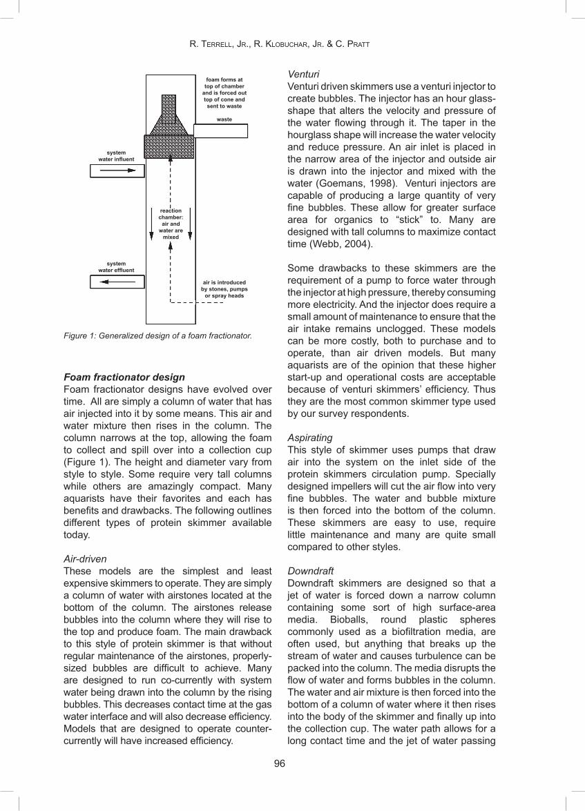
Foam fractionator designFoam fractionator designs have evolved over time. All are simply a column of water that has air injected into it by some means. This air and water mixture then rises in the column. The column narrows at the top, allowing the foam to collect and spill over into a collection cup (Figure 1). The height and diameter vary from style to style. Some require very tall columns while others are amazingly compact. Many aquarists have their favorites and each has benefits and drawbacks. The following outlines different types of protein skimmer available today.
Air-drivenThese models are the simplest and least expensive skimmers to operate. They are simply a column of water with airstones located at the bottom of the column. The airstones release bubbles into the column where they will rise to the top and produce foam. The main drawback to this style of protein skimmer is that without regular maintenance of the airstones, properly-sized bubbles are difficult to achieve. Many are designed to run co-currently with system water being drawn into the column by the rising bubbles. This decreases contact time at the gas water interface and will also decrease efficiency. Models that are designed to operate counter-currently will have increased efficiency.
VenturiVenturi driven skimmers use a venturi injector to create bubbles. The injector has an hour glass-shape that alters the velocity and pressure of the water flowing through it. The taper in the hourglass shape will increase the water velocity and reduce pressure. An air inlet is placed in the narrow area of the injector and outside air is drawn into the injector and mixed with the water (Goemans, 1998). Venturi injectors are capable of producing a large quantity of very fine bubbles. These allow for greater surface area for organics to “stick” to. Many are designed with tall columns to maximize contact time (Webb, 2004).
Some drawbacks to these skimmers are the requirement of a pump to force water through the injector at high pressure, thereby consuming more electricity. And the injector does require a small amount of maintenance to ensure that the air intake remains unclogged. These models can be more costly, both to purchase and to operate, than air driven models. But many aquarists are of the opinion that these higher start-up and operational costs are acceptable because of venturi skimmers’ efficiency. Thus they are the most common skimmer type used by our survey respondents.
AspiratingThis style of skimmer uses pumps that draw air into the system on the inlet side of the protein skimmers circulation pump. Specially designed impellers will cut the air flow into very fine bubbles. The water and bubble mixture is then forced into the bottom of the column. These skimmers are easy to use, require little maintenance and many are quite small compared to other styles.
DowndraftDowndraft skimmers are designed so that a jet of water is forced down a narrow column containing some sort of high surface-area media. Bioballs, round plastic spheres commonly used as a biofiltration media, are often used, but anything that breaks up the stream of water and causes turbulence can be packed into the column. The media disrupts the flow of water and forms bubbles in the column. The water and air mixture is then forced into the bottom of a column of water where it then rises into the body of the skimmer and finally up into the collection cup. The water path allows for a long contact time and the jet of water passing
Figure 1: Generalized design of a foam fractionator.
system water influent
system water effluent
foam forms attop of chamber
and is forced outtop of cone andsent to waste
waste
air is introducedby stones, pumps
or spray heads
reactionchamber:
air andwater are
mixed
R. TeRRell, JR., R. KlobuchaR, JR. & c. PRaTT

97
chaPTeR 10: abioTic filTRaTion meThods foR live coRal sysTems in Public aquaRia
over the media creates a great deal of bubbles. These skimmers tend to be quite large and fairly expensive. But they perform quite well, especially on larger- scale systems. And they have the advantage of halting the production of foam when the skimmate catch reservoir fills up, thus preventing system draining by fractionator overflow.
BeckettFunctioning similar to downdraft models, Beckett style protein skimmers will force water first down a narrow tube before it enters the contact chamber. Instead of using high velocity water passing over media to mix air into the water, this style uses a Beckett foam-generating spray head to inject air into the reaction column. Similar to downdraft skimmers these tend to be quite large. Additionally they can also create quite a bit of noise.
Spray injectionThis style of skimmer uses specially-designed spray nozzles to inject air into a reaction chamber. These units can be as effective as larger units but, because of their design, they are much more compact. They are not widely used at the moment.
Cylofoam™ (Marine Biotech, Beverly, MA, USA)Rather than relying on pumps for circulation, this new design in foam fractionators utilizes a gravity flow to drive water through the unit. Additionally it utilizes a foam extraction and collection device to force the foam out of the vessel, rather than relying on foam to overflow a column. This emerging technology warrants further investigation by the public aquarium industry.
Foam fractionator operational principlesIt is the chemical properties of organic compounds dissolved in the system water that allow them to be removed from system water by the foam fractionation method (Chen, 1993b). Organic compounds are bipolar molecules; they have a hydrophobic end that is repelled by water and a hydrophilic end that is attracted to water. These molecules are also referred to as surfactants. Surfactants are attracted to the air/water interface because the molecule can be oriented in such a way that the hydrophobic end can extend into the air and the hydrophilic end can remain submerged. In foam fractionation bubbles in the reaction column provide an air/
water interface where these surfactants can collect and become concentrated (Figure 2). The large amount of surface area for surfactants to “stick to” make foam fractionators such an effective means of filtration (McCracken and Aiken, 1999)
As the bubbles rise in the column the surfactants are attracted to their surface. These then will condense and form foam at the top of the column (Chen et al., 1993b). This foam is removed by overflowing into a collection cup or to a drain. Foam consistency is the most important consideration of the fractionation process. As the bubbles rise to the top of the contact chamber there are two distinct types of foam that can form; “wet foam” and “dry foam”. For optimal performance the foam produced must be dry in order for the surfactants to flow over into the collection cup when bubbles burst as they leave the water column. If the fractionator is improperly set, the foam will be too “wet”. This will cause the bubbles to burst prematurely. The water may drain back down into the reaction chamber, carrying with it any surfactants that were on the surface of the bubble (Moe, 1989). Additionally foam that is too ”wet” may simply flow over the top of the column and be sentto waste. This can cause considerable water
Figure 2: Air bubbles are coated with surfactants as they rise in the reaction chamber. The hydrophilic ends orient outward and the hydrophobic ends orient into the air bubble.
airbubble
water

98
loss from the system. Foam production can be enhanced and fractionator efficiency improved by the use of ozone mixed into the air supply. Refer to the discussion on ozone use later in this chapter for a more detailed description of its use. The efficiency of foam formation is affected by two major factors; contact time and bubble size. The longer the bubbles are suspended in the water column (referred to as contact time), the longer time they are exposed to the surfactants in the water. Bubble size should be small, ideally in 0.5 to1.0 mm range (Moe, 1989). By having many small bubbles in your column you increase the amount of surface area available for reaction with organics. Additionally small bubbles can increase contact time because they will rise slower through the column than will large bubbles. Contact time can also be increased by using a skimmer with a counter-current flow.
Performance of foam fractionators can be affected by water parameters, particularly by salinity and pH. The process of fractionation does not work well in fresh water mainly because of its typically neutral pH. This reduces electrical interactions between organic and water molecules (Moe, 1989). Foam fractionators work most efficiently at higher salinities and higher pH levels (Webb, 2004).
Even small amounts of lipids in the water can alter surface tension in the system, leading to little to no foam production (Webb, 2004). It is not uncommon to see a reduction in foam for up to several hours after a system has been fed (Timmons et al., 1995).
Foam fractionator placement in life support systems (LSS) designThe style of foam fractionator chosen may determine where in the LSS design it is placed. Ideally it should receive water from the surface of the tank. This is frequently accomplished by allowing water from the tank to overflow into a sump. Water can be either drawn directly from the overflow boxes or from the sump into the foam fractionator. If the LSS design has multiple filtration components, it is best for system water to pass through the foam fractionators first. Any pre-filtering of the water, particularly by a chemical filter, will reduce the fractionator’s efficiency.
The decision on “how much” skimming to use
is really driven by the need of each individual system and relies on close observation and monitoring. The longer the water remains in the column, the more efficiently the skimmer functions. If the turnover rate is too fast, there is not enough contact time between the water and the bubbles. Too low of a flow rate results in no impact because the volume filtered in a given time is insignificant relative to the system volume. The flow rate also depends on the height and diameter of the column. Generally, a narrow column will have a faster flow rate than a wide column and a short column will provide a shorter contact time than a taller one. Opinions on protein skimmer turnover rates vary greatly from some aquarists running them as high as six turnovers per hour to as slow as 2 turnovers per day. Generally most aquarists run them at about one to two tank volumes per hour. Some prefer to have them run full time, while others many only choose to run them intermittently. Some aquarists also turn them off after the addition of trace elements or feeding of fine particulate foods (Moe, 1989).
Foam fractionation in coral systemsWe know it is true that foam fractionation removes protein compounds in the water. Chen et al. (1993b) found the concentration of protein in the foam to be 70 % higher than concentrations in the water being treated. While the majority of the studies conducted on foam fractionation have been conducted on aquaculture systems, fish-only systems and mammal systems, few have looked specifically at their effect on living coral reef tanks. So the question still remains: what else is being removed that may be either beneficial or harmful to a coral system?
In addition to organic proteins, many other compounds are removed to some degree by foam fractionation. These include lipids, amino acids, carbohydrates, enzymes, phenols, phosphates, metals, iodine, algae, bacteria, protozoa and detritus (Dyer and Delbeek, 1991; Moe, 1989). Organic toxins produced by corals, specifically terpenoid compounds produced by soft corals, have also been speculated to be removed through foam fractionation.
Riddle (1999) looked at the effect of adding a protein skimmer to a 7,570 L system containing soft and hard corals. The study specifically looked to test changes in pH, Oxidation-Reduction Potential (ORP), Dissolved Oxygen (DO), five-day Biochemical Oxygen Demand
R. TeRRell, JR., R. KlobuchaR, JR. & c. PRaTT

99
chaPTeR 10: abioTic filTRaTion meThods foR live coRal sysTems in Public aquaRia
(BOD5), oxygen consumption rate (OCR), dissolved carbon dioxide (CO2), APHA color and Photosynthetically Active Radiation (PAR). The most significant findings in the study were a reduction in color from 10 units to 5 units on the APHA color scale (after 24.5 h) and an increase in PAR-intensity of 17 %. Organics in the system water can tend to turn the water yellow in color, reducing light transmission. By adding a protein skimmer to the system they were able to remove organic pollutants that were contributing to coloration in the water and greatly improve light transmission into the system. Considering the importance of light to any coral system this should be seen as a great benefit of foam fractionation.
Another study conducted at the National Aquarium in Baltimore in 1999 found an improvement in water quality stability of their 18,927 L coral system. While the overall water quality remained relatively the same, the amount of water changes necessary to maintain their values significantly decreased after the addition of a foam fractionator. Prior to its addition, water changes of 10 % were conducted every 7-14 d. After the addition of a fractionator, the need for water changes was practically eliminated in the system. In fact, there was only a need for two water changes in a 9 month period (a combined total of less than 15 % of the system volume) (McCracken and Aiken, 1999).Sondervan (2001) analyzed foam collected from a foam fractionator running on an invertebrate system at the Artis Zoo Aquarium. Levels of calcium in the foam were found to be 30 % higher than in natural seawater. This suggests that the process of foam fractionation may be removing calcium from system water so careful monitoring of calcium levels is important for optimal system health. There is truly a need for further research on foam fractionator use in coral reef tank LSS design. Some concerns raised in the aquarium community include the possible removal of or damage to phytoplankton needed by filter feeders in a coral system. Additionally there is some concern that protein skimming may remove trace elements needed by corals. So it is advisable to monitor and replace trace elements over time (Moe, 1989; Dyer and Delbeek, 1991). We know that coral reefs, by their very nature, are delicate systems requiring optimal water conditions for their success. Foam fractionators have been demonstrated to be an effective
tool in successfully maintaining these dynamic living systems in a captive environment.
ozone
Ozone is a strong oxidant made up of three oxygen molecules. Oxidation-Reduction Potential (ORP) is measured in millivolts (mV) and is the sum of all reactions, or half-reactions, involving the transfer of electrons (www5). Addition of ozone results in elevated ORP and can produce persistent oxidants which, collectively, are called Total Residual Oxidants (TRO). These substances are a potential hazard to marine life if they enter the exhibit. While fishes can tolerate up to 0.05 mg.L-1 TRO, corals can only tolerate 0.02 mg.L-1 TRO (www5). For this reason when ozone is used on live coral systems, it is generally applied in a protein skimmer. This makes ozone use safer as the Applied Ozone Dose (AOD) is generally ten or more times less than AOD in a contact/degas system (www5), thereby reducing the potential for measurable TRO in the system.
To ensure the safety of the aquarium inhabitants, especially sensitive invertebrates, it is crucial that a thorough and active monitoring system be employed. Firstly, the AOD must be calculated from the water and gas flow rates entering the protein skimmer and the concentration of ozone in the gas mixture. Secondly, ORP probe(s) must be calibrated frequently. This frequency will depend on the construction, brand and placement of the probe. But weekly calibration is often recommended. Thirdly, the TRO must be measured frequently. Lastly, the system should be observed closely with regard to behavior of the inhabitants, husbandry practices, and function of the ORP controller (Aiken, pers. com.). The AOD should be set such that the ozone flow is always on. The ORP should be remain relatively constant in the ideal range of 300-380 mV, only dropping slightly following feeds, tank cleaning, or other significant husbandry events (www5).
Ozone reduces water color from dissolved organics by oxidation of those organic molecules. It improves skimmer function by micro-flocculation of suspended organics. And ozone can reduce pathogen occurrence inlive coral systems through sterilization of the water it contacts (www5). All of these functionstogether can lead to increased light penetration,

100
decreased algal nutrients and decreased pathogen concentrations in the system. Obviously these are all potential benefits to the aquarist maintaining live corals.
In our survey of public aquaria, ozone was generally used continuously only in systems greater than 15,000 L. This limitation is largely a function of the financial and time commitments required to operate ozone on a live coral system in a safe and effective manner. But this filtration option should be more widely used by public aquaria as the benefits far outweigh the costs.
ConClusIon
Keeping corals alive in aquariums is something that has been done for many years. However, advancements and the rise of new technologies, equipment, and products over recent years have provided aquarists many more options for filtration. Increasingly efficient mechanical filters, advancements in knowledge of chemical filtration media, creation of new dynamic foam fractionators, and even the use of ozone on coral systems have allowed animals that were once thought impossible to keep in captivity to be kept with great successes. By combining the increased diversity of abiotic and biological filtration options, aquarists are able to create many coral systems that thrive while appearing completely different from one another. At the same time, these filtration devices allow aquarists to keep their charges with less effort. This, in turn, will lead to more advances in coral husbandry and propagation in public aquaria.
reFerenCes
Aiken, A., 2000. Application and Benefits of RetrofittingFoam Fractionator to Existing Life Support Systems. Proceedings of the 2000 American Zoo and Aquarium Association Nation Conference. Orlando, Florida, USA.
Aiken, A., D. Warmolts, D.L. Labonne, and S.L. Bailey,2001. Large scale foam fractionation: a different approach to creating mixed species environments for marine systems. Fifth International Aquarium Congress. Proceedings, 20(1):157-164.
Chen, S., M.B. Timmons, J.J. Bisogni Jr. and D.J.Aneshansley, 1993a. Suspended-solids removal by foam fractionation. Progressive Fish-Culturist, 55(2):69-75.
Chen, S., MB Timmons, J.J. Bisogni Jr, and D.J.Aneshansley, 1993b. Protein and its removal by foam fractionation. Progressive Fish-Culturist, 55(2):76-82.
Delbeek, J.C. and J. Sprung. 2005. The Reef Aquarium:Science, Art, and Technology. Volume three. Two Little Fishies, Inc., Coconut Grove, FL. USA. 680 pp.
Dyer, S. and J.C. Delbeek, 1991. To skim or not to skim?That is the question. Aquarium Fish Magazine, 3(4):32-43.
Escobal, P.R. 2000. Aquatic Systems Engineering:Devices and How They Function. Expanded Second Edition. Dimension Engineering Press. Oxnard, CA. USA, 272 pp.
Goemans, B. 1998. The reef scene. Protein skimmers,part II. Tropical Fish Hobbyist, 511(1):50-56.
Hovanec, T. and E.F. DeLong, 1996. ComparativeAnalysis of Nitrifying Bacteria Associated with Freshwater and Marine Aquaria. Applied and Environmental Biology, 62(8):2888-2896
La Bonne, D.L, 1998. Today’s Innovation in LifeSupport Technology Set to the Stage for the 21st Century. Proceeding for the 1998 AZA Eastern Regional Conference. Boston Massachusetts.
McCracken, K. and A. Aiken, 1999. Practical applicationof large-scale protein skimming. Freshwater and Marine Aquarium, 22(5):197-200.
McEwan, T. Active Filter Media (AFM), a glass product,an alternative media for Sand Filters. EUAC, 2005.
Moe, M., 1989. The Marine Aquarium Reference,Systems and Invertebrates. Green Turtle Publications. 510 pp.
Moe, M.A. Jr., 1992. The Marine Aquarium Reference:Systems and Invertebrates. Green Turtle Publications. Plantation, FL. USA, 512 pp.
Paletta, M., 1988. The Relationship of Redox Potential toMicro-algae. Seascope Aquarium Systems, Vol. 5, Winter 1988.
Paletta, M., 1989. Suggestions for Reef Maintenance.Seascope Aquarium Systems, Vol. 6, Summer 1989.
Riddle, D., 1999. Effects of protein skimming (foamfractionation) on a closed system aquarium. Freshwater and Marine Aquarium, 22(6):76,78,80,82.
Sigworth, E.A. and S.B. Smith, 1972. Adsorption ofInorganic Compounds by Activated Carbon. Journal AWWA, Water Technology/Quality, June 1972.
Sondervan, P.J., 2001. The relationship of calciumloss with trace element concentrations in seawater life systems. Fifth International Aquarium Congress, Monaco Institut Oceanographique Bulletin, 20(1):139-148.
Spotte, S.H., 1970. Fish and Invertebrate Culture: Watermanagement in closed systems. Wiley-Intersciense, New York: 145 pp.
Spotte, S., 1979. Seawater Aquariums: The CaptiveEnvironment. John Wiley & Sons, Inc., New York, USA. 413 pp.
Spotte, S., 1992. Captive Seawater Fishes: Science andTechnology. John Wiley & Sons, Inc., New York, USA. 942 pp.
Timmons, M. B., S. Chen and N.C. Weeks, 1995.Mathematical model of a foam fractionator used in aquaculture. Journal of the World Aquaculture Society, 26(3):225-233.
Webb, J., 2004. Venturi foam fractionation: guidelines foroperation. Aquaculture Magazine, 30(5):48-51.
R. TeRRell, JR., R. KlobuchaR, JR. & c. PRaTT

101
chaPTeR 10: abioTic filTRaTion meThods foR live coRal sysTems in Public aquaRia
PersonAl CoMMunICAtIons
Aiken, A., 2007. National Aquarium in Baltimore, Baltimore, MD 21202 USACollins, M., 2007. Mote Marine Aquarium, Sarasota, FL 34236 USACurlee, K., 2007. Georgia Aquarium, Atlanta, GA 30313 USAHemdal, J., 2007. Toledo Zoo, Toledo, OH 43614 USAJanse, M., 2007. Burgers’ Zoo, Arnhem, The NetherlandsMcEwan, T., 2007. The Scientific Center, Salmiya, KuwaitYaiullo, J., 2007. Atlantis Marine World, Riverhead, NY 11901 USA
Internet resourCes
www1. http://www.drydenaqua.com/afm/index.htm www2. http://www.marineland.com/science/ articles/16ActivatedCarb.asp www3. http://www.advancedaquarist.com/issues/ july2003/chem.htm www4. http://www.advancedaquarist.com/issues/ june2004/review.htm www5. http://www.aqualitysymposium.org/ppts/ chemicalprocesses/SMITH%20Ozone%20 dosing%20and%20control.PPTwww6. http://www.reefkeeping.com/issues/2003-04/rhf/ feature/index.phpwww7. http://www.korallen-zucht.de/files/ zeoguide_103_english-1.pdf
Table 1: Abiotic LSS survey results (n=35)
Mechanicalrapid sand filterfilter bagpressurized bag filterfilter flossdiatomaceous earth filtercartridge/pleated filtersettling sumprotating drum filterpowerhead w/spongereverse flow UGFfilter sponge after overflow Chemicalozone in fractionatorozone in contactorcarbonaluminium oxideiron oxidePoly Filter1
synthetic polymer resinKent Marine Phosphate Sponge2
lanthanum chloride Ultraviolet sterilizer Foam fractionatorsventuridowndraftbeckettaspirating/needle wheelspray injection
Continuous #
286
110704
150111
20
60
121520
01
3
342713
231
Continuous %
801731
20
1143
333
5717
343
146
3
9
977737
693
Intermittent #
1517046010000
20
30
152211
32
3
110000
Intermittent %
433
20
1117
3
57
9
436633
96
9
33
1 Poly Filter, Poly Bio Marine, Reading, PA USA2 Phosphate Sponge, Kent Marine, Franklin, WI USA

102
APPEnDix 1: Abiotic life support survey
Contact name:Contact title:
Institution:e-mail address:
telephone number:live coral exhibit size range (units):
______________________________________________________________________________________________________________________________________________________________________________
Mechanical filtrationrapid sand filterfilter bag/sock on surface skimmerpressurized bag filterfilter flossdiatomaceous earth filtercartridge/pleated filtersettling sumprotating drum filterother mechanical (please specify below)
Chemical Mediaozone in foam fractionatorozone in contact chambercarbonaluminum oxideiron oxidePoly Filtersynthetic polymer resin (please specify below)
other chemical media(please specify below)
UV SterilizerFoam Fractionators/Protein Skimmersventuridowndraftbeckettother skimmer (please specify below)
Continuous use
________________________________________________________________________________________________________
_______________________________________
______________________________________________________________________________
__________________________
____________________________________________________
_______________________________________
__________________________
Intermittent use
________________________________________________________________________________________________________
_______________________________________
______________________________________________________________________________
__________________________
____________________________________________________
_______________________________________
__________________________
R. TeRRell, JR., R. KlobuchaR, JR. & c. PRaTT