Chapter 1 Properties and Uses of Metal...magnetic qualities of the metal. Mechanical properties...
233
NAVEDTRA 14251A 1-1 Chapter 1 Properties and Uses of Metal Topics 1.0.0 Properties of Metal and Metal Alloys 2.0.0 Mechanical Properties 3.0.0 Corrosion Resistance 4.0.0 Ferrous Metals and Alloys 5.0.0 Nonferrous Metal and Alloys 6.0.0 Advanced Metal Identification To hear audio, click on the box. Overview As a steelworker, you will be looked upon as the subject matter expert on everything metal. You will be expected to build, repair, and refurbish almost everything metal. Knowing how to identify the metals you will be working with is one of the foundations of your rate. To carry out these responsibilities skillfully, you must possess a sound working knowledge of various metals and their properties. Once you learn how to identify different metals confidently, beyond the ferrous/nonferrous determination you learned in Steelworker Basic, you can make the proper decisions pertaining to materials and tools you will need to complete the job. You will work mainly with the ferrous metals iron and steel; however, you must also become familiar with and be able to differentiate between the nonferrous metals. This chapter will discuss the properties of different metals in greater detail and show how to use simple tests to help identify common metals. Objectives When you have completed this chapter, you will be able to do the following: 1. Identify the properties of metal and metal alloys. 2. Describe the properties of metal and metal alloys. 3. Identify mechanical properties of metal. 4. Describe the concept of corrosion resistance. 5. Describe the different types of ferrous metals and alloys. 6. Describe the different types of nonferrous metals and alloys. 7. Interpret advanced metal identification.
Transcript of Chapter 1 Properties and Uses of Metal...magnetic qualities of the metal. Mechanical properties...

NAVEDTRA 14251A 1-1
Chapter 1
Properties and Uses of Metal
Topics
1.0.0 Properties of Metal and Metal Alloys
2.0.0 Mechanical Properties
3.0.0 Corrosion Resistance
4.0.0 Ferrous Metals and Alloys
5.0.0 Nonferrous Metal and Alloys
6.0.0 Advanced Metal Identification
To hear audio, click on the box.
Overview
As a steelworker, you will be looked upon as the subject matter expert on everything metal. You will be expected to build, repair, and refurbish almost everything metal. Knowing how to identify the metals you will be working with is one of the foundations of your rate. To carry out these responsibilities skillfully, you must possess a sound working knowledge of various metals and their properties.
Once you learn how to identify different metals confidently, beyond the ferrous/nonferrous determination you learned in Steelworker Basic, you can make the proper decisions pertaining to materials and tools you will need to complete the job. You will work mainly with the ferrous metals iron and steel; however, you must also become familiar with and be able to differentiate between the nonferrous metals. This chapter will discuss the properties of different metals in greater detail and show how to use simple tests to help identify common metals.
Objectives
When you have completed this chapter, you will be able to do the following:
1. Identify the properties of metal and metal alloys.
2. Describe the properties of metal and metal alloys.
3. Identify mechanical properties of metal.
4. Describe the concept of corrosion resistance.
5. Describe the different types of ferrous metals and alloys.
6. Describe the different types of nonferrous metals and alloys.
7. Interpret advanced metal identification.

NAVEDTRA 14251A 1-2
Prerequisites
None
This course map shows all of the chapters in Steelworker Advanced. The suggested training order begins at the bottom and proceeds up. Skill levels increase as you advance on the course map.
Welding Costs
S
T
E
E
L
W
O
R
K
E
R
A
D
V
A
N
C
E
D
Metal Fence System
Fabrication and Placement of Reinforcing Steel
Layout and Fabrication of Structural Steel and Pipe
Properties and Uses of Metal
Features of this Manual
This manual has several features that make it easy to use online.
Figure and table numbers in the text are italicized. The Figure or table is either next to or below the text that refers to it.
The first time a glossary term appears in the text, it is bold and italicized. When your cursor crosses over that word or phrase, a popup box displays with the appropriate definition.

NAVEDTRA 14251A 1-3
Audio and video clips are included in the text, with an italicized instruction telling you where to click to activate it.
Review questions that apply to a section are listed under the Test Your Knowledge banner at the end of the section. Select the answer you choose. If the answer is correct, you will be taken to the next section heading. If the answer is incorrect, you will be taken to the area in the chapter where the information is for review. When you have completed your review, select anywhere in that area to return to the review question. Try to answer the question again.
Review questions are included at the end of this chapter. Select the answer you choose. If the answer is correct, you will be taken to the next question. If the answer is incorrect, you will be taken to the area in the chapter where the information is for review. When you have completed your review, select anywhere in that area to return to the review question. Try to answer the question again.

NAVEDTRA 14251A 1-4
1.1.1 PROPERTIES of METAL and METAL ALLOYS
Metals in general have high electrical conductivity, thermal conductivity, luster and density, and the ability to be deformed under stress without cleaving. Chemical elements lacking these properties are classed as nonmetals. A few elements, known as metalloids, sometimes behave like a metal and at other times like a nonmetal. Some examples of metalloids are as follows: boron, arsenic, and silicon.
As you have already studied, metals are divided into two classes, ferrous and nonferrous. Ferrous metals are those in the iron class and are magnetic in nature. These metals consist of iron, steel, and alloys related to them. Nonferrous metals are those that contain either no, or very small amounts of, ferrous metals. These are generally divided into the aluminum, copper, magnesium, lead, and similar groups.
Although you will hardly ever work with pure metals, you need to be knowledgeable of their properties because the alloys you will work with are combinations of pure metals. Some of the pure metals discussed in this chapter are the base metals in these alloys, especially iron, aluminum, and magnesium. Other metals discussed are the alloying elements present in small quantities but important in their effect, including chromium, molybdenum, titanium, and manganese.
An alloy is a mixture of two or more elements in solid solution in which the main element is a metal. Most pure metals are either too soft, brittle, or chemically reactive for practical use. Combining different ratios of metals as alloys modifies the properties of the resultant metals to produce desirable characteristics. The reason for making alloys is generally to create a less brittle, harder, corrosion resistant material, or one with a more desirable color and luster.
Of the metallic alloys in use today, the alloys of iron (steel, stainless steel, cast iron, tool steel, alloy steel) make up the largest proportion by both quantity and commercial value. Iron alloyed with various proportions of carbon gives low-, mid- and high-carbon steels, and as the carbon levels increase, ductility and toughness decrease. The addition of silicon will produce cast irons, while the addition of chromium, nickel, and molybdenum to carbon steels (more than 10%) results in stainless steels.
Aluminum, titanium, copper, and magnesium alloys are also significant in commercial value. Copper alloys have been around since prehistory—bronze gave the Bronze Age its name—and have many applications today, most importantly in electrical wiring. The alloys of aluminum, titanium, and magnesium are valued for their high strength-to- weight ratios. These materials are ideal for situations where high strength-to-weight ratio is more important than material cost, such as in aerospace and some automotive applications.
Alloys specially designed for highly demanding applications, such as jet engines, may contain more than ten elements.

NAVEDTRA 14251A 1-5
Table 1-1 is a list of various elements and their symbols that compose metallic materials.
Table 1-1 Symbols of Base Metals and Alloying Elements.
Element Symbol
Aluminum Al
Antimony Sb
Cadmium Cd
Carbon C
Chromium Cr
Cobalt Co
Copper Cu
Iron Fe
Lead Pb
Magnesium Mg
Manganese Mn
Molybdenum Mo
Nickel Ni
Phosphorus P
Silicon Si
Sulfur S
Tin Sn
Tungsten W
Vanadium V
Zinc Zn
Since you will work mostly with alloys, you need to understand their characteristics. The characteristics of elements and alloys are explained in terms of physical, chemical, electrical, and mechanical properties.
Physical properties relate to color, density, weight, and heat conductivity.
Chemical properties involve the behavior of the metal when placed in contact with the atmosphere, salt water, or other substances.
Electrical properties encompass the electrical conductivity, resistance, and magnetic qualities of the metal.
Mechanical properties relate to load-carrying ability, wear resistance, hardness, and elasticity.
When selecting stock for a job, your main concern is the mechanical properties of the metal. The various properties of metals and alloys were determined in the manufacturers’ laboratories and by various societies interested in metallurgical development. Charts presenting the properties of a particular metal or alloy are available in many commercially published reference books. The charts provide information on the melting point, tensile strength, electrical conductivity, magnetic properties, and other properties of a particular metal or alloy. Simple tests can be conducted to determine some of the properties of a metal; however, we normally use a metal test only as an aid for identifying a piece of stock. Some of these methods of testing are discussed later in this chapter.

NAVEDTRA 14251A 1-6
2.1.1 MECHANICAL PROPERTIES
Strength, hardness, toughness, elasticity, plasticity, brittleness, and ductility and malleability are mechanical properties used as measurements of how metals behave under a load. These properties are described in terms of the types of force or stress that the metal must withstand and how these are resisted. Common types of stress are compression, tension, shear, torsion, impact, or a combination of these stresses, such as fatigue (Figure. 1-1).
Figure 1-1 — Stress applied to a material.
Compression stresses develop within a material when forces compress or crush the material. A column that supports an overhead beam is in compression, and the internal stresses that develop within the column are compression.
Tension (or tensile) stresses develop when a material is subject to a pulling load, for example, when using a wire rope to lift a load or when using it as a guy to anchor an antenna. “Tensile strength” is defined as resistance to longitudinal stress or pull, and can be measured in pounds per square inch of cross section.
Shearing stresses occur within a material when external forces are applied along parallel lines in opposite directions. Shearing forces can separate material by sliding part of it in one direction and the rest in the opposite direction.
Some materials are equally strong in compression, tension, and shear. However, many materials show marked differences; for example, cured concrete has a maximum strength of 2,000 psi in compression, but only 400 psi in tension. Carbon steel has a maximum strength of 56,000 psi in tension and compression but a maximum shear strength of only 42,000 psi; therefore, when dealing with maximum strength, you should always state the type of loading.
Fatigue is the tendency of a material to fail after repeated bending at the same point. A repeatedly stressed material usually fails at a point considerably below its maximum strength in tension, compression, or shear. For example, a thin steel rod can be broken by hand by bending it back and forth several times in the

NAVEDTRA 14251A 1-7
same place; however, if the same force is applied in a steady motion (not bent back and forth), the rod cannot be broken.
2.1.1 Strength
Strength is the property that enables a metal to resist deformation under load.
Compressive strength is the maximum load in compression a material will withstand before a predetermined amount of deformation, or the ability of a material to withstand pressures acting in a given plane. The compressive strength of both cast iron and concrete is greater than their tensile strength. For most materials, the reverse is true.
Tensile strength is defined as the maximum load in tension a material will withstand before fracturing, or the ability of a material to resist being pulled apart by opposing forces. Also known as ultimate strength, it is the maximum strength developed in a metal in a tension test. (The tension test is a method for determining the behavior of a metal under an actual stretch loading. This test provides the elastic limit, elongation, yield point, yield strength, tensile strength, and the reduction in area.) The tensile strength is the value most commonly given for the strength of a material and is given in pounds per square inch (psi) or kilo-Pascals (kPa). The tensile strength is the number of pounds of force required to pull apart a bar of material 1.0 in. (25.4 mm) wide and 1.00 in. (25.4 mm) thick.
Shear strength is the ability of a material to resist being fractured by opposing forces acting in a straight line but not in the same plane, or the ability of a metal to resist being fractured by opposing forces not acting in a straight line.
Fatigue strength is the maximum load a material can withstand without failure during a large number of reversals of load. For example, a rotating shaft that supports a weight has tensile forces on the top portion of the shaft and compressive forces on the bottom. As the shaft is rotated, there is a repeated cyclic change in tensile and compressive strength. Fatigue strength values are used in the design of aircraft wings and other structures subject to rapidly fluctuating loads. Fatigue strength is influenced by microstructure, surface condition, corrosive environment, and cold work. Impact strength is the ability of a metal to resist suddenly applied loads and is measured in foot-pounds of force.
2.2.0 Hardness
Hardness is defined as resistance of metal to plastic deformation, usually by indentation. However, the term may also refer to stiffness (temper) or to resistance to scratching, abrasion, or cutting. It is the property of a metal which gives it the ability to resist being permanently deformed (bent, broken, or have its shape changed) when a load is applied. The greater the hardness of the metal, the greater resistance it has to deformation. There are several methods of measuring the hardness of a material, so hardness is always specified in terms of the particular test used.
The metals industry uses three types of hardness tests with accuracy: the Brinell, Rockwell, and Vickers hardness tests. Since the definitions of metallurgic ultimate strength and hardness are rather similar, it can generally be assumed that a strong metal is also a hard metal.
These hardness tests measure a metal's hardness by determining the metal's resistance to the penetration of a non-deformable ball or cone. The tests determine the

NAVEDTRA 14251A 1-8
depth to which such a ball or cone will sink into the metal under a given load within a specific period of time.
Of these three tests, Rockwell is the most frequently used, the basic principle being that a hard material can penetrate a softer one, so you measure the amount of penetration and compare it to a scale.
In regular Rockwell testing the minor load is always 10 kgf (kilograms of force). The major load can be any of the following loads: 60 kgf, 100 kgf, or 150 kgf. No Rockwell hardness value is specified by a number alone. It must always be prefixed by a letter signifying the value of the major load and type of penetrator (e.g., HRC 35). A letter has been assigned for every possible combination of load and penetrator, as given in Table 1-2. Each test yields a Rockwell hardness value on your tester. Testers with dial gauges have two sets of figures: red and black. When the diamond penetrator is used, the readings are taken from the black divisions. When testing with any of the ball penetrators, the readings are taken from the red divisions. Testers with digital displays have a scale selection switch, allowing an automatic display of the Rockwell hardness number on its screen.
Table 1-2 — Rockwell Hardness Scale.
Scale symbol Penetrator Load in Kilograms-Force (Kgf)
A* Diamond tip* 60
B 1/16” ball 100
C Diamond tip 150
D Diamond tip 100
E 1/8” ball 100
F 1/16” ball 60
G 1/16” ball 150
H 1/8” ball 60
K 1/8” ball 150
L 1/4“ ball 60
M 1/4“ ball 100
P 1/4“ ball 150
R 1/2” ball 60
S 1/2” ball 100
V 1/2” ball 150
* Two scales – carbide and steel.

NAVEDTRA 14251A 1-9
The regular Rockwell scales are established such that an infinitely hard material will read 100 on the diamond penetrator scales and 130 on the ball penetrator scales. One regular Rockwell number represents a penetration of 0.002 mm (0.000080 inch). Therefore, a reading of C60 indicates penetration from a minor to major load of (100 to 60 Rockwell points) x 0.002 mm = 0.080 mm or 0.0032 inch. A reading of B80 indicates a penetration of (130 to 80 Rockwell points) x 0.002 = 0.100 mm or 0.004 inch (Figure 1-2).
A full explanation of the various methods used to determine the hardness of a material is available in commercial books or books located in your base library. ASTM publishes standards for every type of hardness test. Use these standards for the type of testing you will be performing as they are the most up-to-date standards available.
Figure 1-2 — Rockwell testing.

NAVEDTRA 14251A 1-10
2.3.0 Toughness
Toughness is the property that enables a material to withstand shock and be deformed without rupturing. Toughness may be considered as a combination of strength and plasticity. Table 1-3 shows the order of some of the more common materials for toughness as well as other properties.
Table 1-3 — Mechanical Properties of Metals/Alloys.
Toughness
Brittleness
Ductility
Malleability
Corrosion Resistance
Copper White cast iron Gold Gold Gold
Nickel Gray cast iron Silver Silver Platinum
Iron Hardened steel Platinum Aluminum Silver
Magnesium Bismuth Iron Copper Mercury
Zinc Manganese Nickel Tin Copper
Aluminum Bronzes Copper Lead Lead
Lead Aluminum Aluminum Zinc Tin
Tin Brass Tungsten Iron Nickel
Cobalt Structural steels Zinc Iron
Bismuth Zinc Tin Zinc
Monel Lead
Magnesium
Tin Aluminum
Copper
Iron
Metals/alloys are ranked in descending order of having the property named in the column heading.
2.4.0 Elasticity
When a material has a load applied to it, the load causes the material to deform. Elasticity is the ability of a material to return to its original shape after the load is removed. Theoretically, the elastic limit of a material is the limit to which a material can be loaded and still recover its original shape after the load is removed.
All materials are elastic to some extent. It may surprise you to learn that a piece of steel is more elastic than a rubber band. The rubber band stretches more than the steel since it is more easily strained, but the steel returns more nearly to its original shape and size and is, therefore, more truly elastic.
2.5.0 Plasticity
Plasticity describes the ability of materials to undergo irreversible deformation without fracture or damage. This property is the opposite of strength. By careful alloying of metals, the combination of plasticity and strength is used to manufacture large structural members. For example, should a member of a bridge structure become overloaded, plasticity allows the overloaded member to flow, allowing the distribution of the load to

NAVEDTRA 14251A 1-11
other parts of the bridge structure. Sheet aluminum has a high plasticity, whereas tool steel has a very low plasticity.
2.6.0 Brittleness
Brittleness is the opposite of plasticity. A brittle metal will break or shatter before it deforms if bent or struck a sharp blow. Generally, brittle metals are high in compressive strength but low in tensile strength. For example, cast iron is very brittle, so you would not use cast iron for fabricating support beams in a bridge.
2.7.1 Ductility and Malleability
The properties known as ductility and malleability are special cases of plasticity.
Ductility is the property that makes it possible for a material to withstand extensive permanent deformation from tension. It can be stretched or drawn out into a thin wire. A very ductile metal such as copper or aluminum may be pulled through dies to form wire.
Malleability is the property that makes it possible for a material to withstand extensive permanent deformation from compression. It can be stamped, hammered, or rolled into thin sheets.
Most metals that exhibit one of these properties also exhibit the other. However, this is not always true. Lead, for example, is very malleable (it can be permanently deformed in compression without breaking), but it is not ductile (it cannot be permanently deformed in tension to any great extent).
3.0.0 CORROSION RESISTANCE Corrosion resistance is the property that enables a material to resist entering into chemical combination with other substances from attacks by atmospheric, chemical, or electrochemical conditions. A high degree of corrosion resistance is very desirable in all metals exposed to weather elements. Most metals are easily corroded, however, as shown by the fact that pure metals occur only rarely in nature. One of the most common examples of corrosion, sometimes called oxidation, is illustrated by the rusting of iron.
The presence of impurities or the presence of alloying elements may greatly alter the corrosion resistance of a metal. For example, the zinc that is known as “commercially pure” contains a small amount of impurities; this grade of zinc corrodes about 10,000 times as fast as zinc that is chemically pure. On the other hand, many alloys have been developed for the particular purpose of increasing the corrosion resistance of the material. For example, pure iron would be entirely unsuitable for use in boilers because it has very poor resistance to corrosion, particularly at high temperatures; yet alloys composed primarily of iron are used successfully for this service.
4.0.0 FERROUS METALS and ALLOYS
The following discussion is a refresher of SW Basic Chapter 1. Ferrous metals are metals that contain iron. Ferrous metals appear in the form of cast iron, carbon steel, and tool steel. The various alloys of iron, after undergoing certain processes, are pig iron, gray cast iron, white iron, white cast iron, malleable cast iron, wrought iron, alloy steel, and carbon steel. All these types of iron are mixtures of iron and carbon, manganese, sulfur, silicon, and phosphorous. Other elements are also present, but in amounts that do not appreciably affect the characteristics of the metal. Normally, ferrous metals are magnetic and nonferrous metals are nonmagnetic.

NAVEDTRA 14251A 1-12
4.1.0 Iron
Pure iron rarely exists outside of the laboratory. Iron is produced by reducing iron ore to pig iron by using a blast furnace. From pig iron, many other types of iron and steel are produced by the addition or deletion of carbon and alloys. The following paragraphs discuss the different types of iron and steel that can be made from iron ore.
4.1.1 Pig Iron
Pig iron is about 93% iron, from 3% to 5% carbon, with various amounts of other elements. Pig iron is comparatively weak and brittle; therefore, it has a limited use as is (cast iron pipe and some fittings and valves), and approximately ninety percent of it is refined to produce steel.
4.1.2 Wrought Iron
Wrought iron is almost pure iron. It is made from pig iron in a puddling furnace and has a carbon content of less than 0.08 percent. Carbon and other elements present in pig iron are taken out, leaving almost pure iron. In the process of manufacture, some slag is mixed with iron to form a fibrous structure in which long stringers of slag, running lengthwise, are mixed with long threads of iron. Because of the presence of slag, wrought iron resists corrosion and oxidation which cause rusting.
The chemical analyses of wrought iron and mild steel are just about the same. The difference comes from the properties controlled during the manufacturing process. Wrought iron can be gas and arc welded, machined, plated, and easily formed; however, it has a low hardness and a low fatigue strength.
4.1.3 Cast Iron
Cast iron is a manmade alloy of iron, carbon, and silicon. A portion of the carbon exists as free carbon or graphite. Cast iron is any iron containing greater than 2% carbon alloy, with most cast irons ranging between 2.1% to 4% by weight. Cast iron has a high- compressive strength and good wear resistance; however, it lacks ductility, malleability, and impact strength. Alloying it with nickel, chromium, molybdenum, silicon, or vanadium improves toughness, tensile strength, and hardness. A malleable cast iron is produced through a prolonged annealing process.
4.1.4 Ingot Iron
Ingot iron is a commercially pure (99.85% iron), easily formed iron, with good ductility and corrosion resistance. The chemical analysis and properties of ingot iron are practically the same as the lowest carbon steel. The lowest carbon steel, known as dead-soft, has about 0.06% more carbon than ingot iron.
Carbon content in iron is considered an impurity; carbon content in steel is considered an alloying element. The primary use for ingot iron is for galvanized and enameled sheet.
4.2.0 Steel
Steel is an alloy consisting mostly of iron, with carbon content between 0.2% and 2.1% by weight, depending on the grade. Steel contains less carbon than cast iron (2.1% to 4%), but considerably more than wrought iron (less than 0.08%). Basic carbon steels are alloyed with other elements, such as chromium and nickel, to increase certain physical properties of the metal. Steel can be machined, welded, and forged, all to varying degrees, depending on the type of steel.

NAVEDTRA 14251A 1-13
Steels and other metals are classified based on method of manufacture, method of shaping, method of heat treatment, properties, intended use, and chemical composition. In addition, certain steels and other metals are often referred to by trade names.
Probably the most reasonable way to classify steels is by their chemical composition. Steels that derive their properties primarily from the presence of carbon are referred to merely as “steels” or sometimes as “plain carbon steels.” Steels that derive their properties primarily from the presence of some alloying element other than carbon are referred to as “alloys” or “alloy steels.”
4.2.1 Low-Carbon Steel
Low-carbon steel (0.05% to 0.30% carbon) is tough and ductile, and can be rolled, punched, sheared, and worked when either hot or cold. It is easily machined and can readily be welded by all methods. It does not respond to heat-treating; however, it can easily be case hardened.
4.2.2 Medium-Carbon Steel
Medium-carbon steel (0.30% to 0.45% carbon) is strong and hard but cannot be welded or worked as easily as the low-carbon steels. It may be heat-treated after fabrication. It is used for general machining and forging of parts that require surface hardness and strength, such as crane hooks, axles, shafts, setscrews, and so on. Medium-carbon steel is made in bar form in the cold-rolled or the normalized and annealed condition. During welding, the weld zone will become hardened if cooled rapidly and must be stress-relieved after welding.
4.2.3 High-Carbon Steel/Very High-Carbon Steel
High-carbon steel (0.45% to 0.75% carbon) and very high-carbon steel (0.75% to 1.70% carbon) respond well to heat treatment and can be welded with difficulty, but the welding must be done using specific processes due to the hardening effect of heat at the welded joint. This steel is used for the manufacture of drills, taps, dies, springs, and other machine tools and hand tools that are heat-treated after fabrication to develop the hard structure necessary to withstand high shear stress and wear. It is manufactured in bar, sheet, and wire forms, and in the annealed or normalized condition in order to be suitable for machining before heat treatment.
Tool steel (0.70% to 1.40% carbon) refers to a special variety of carbon and alloy steels particularly well suited to be made into tools. Tool steels are made to a number of grades for different applications. Choice of grade depends on, among other things, whether a keen cutting edge is necessary, abrasion resistance is paramount, or the tool must withstand impact loading encountered with such tools as axes, pickaxes, and quarrying implements.
Tool steel is used to manufacture chisels, shear blades, cutters, large taps, woodturning tools, blacksmith’s tools, razors, and similar parts where high hardness is required to maintain a sharp cutting edge. It is very difficult to weld due to the high carbon content. A spark test shows a moderately large volume of white sparks having many fine, repeating bursts.
4.2.4 Low-Alloy, High-Strength, Tempered Structural Steel
This is a special low-carbon steel, containing specific small amounts of alloying elements, that is quenched and tempered to get a yield strength greater than 50,000 psi and tensile strengths of 70,000 to 120,000 psi. Structural members made from these

NAVEDTRA 14251A 1-14
high-strength steels may have smaller cross-sectional areas than common structural steels and still have equal or greater strength. Additionally, these steels are normally more corrosion and abrasion resistant. High-strength steels are covered by ASTM specifications.
NOTE
This type of steel is much tougher than low-carbon steels. Shearing machines for this type of steel must have twice the capacity than that required for low-carbon steels.
4.2.5 Stainless Steel
This type of steel is classified by the American Iron and Steel Institute (AISI) into two general series named the 200-300 series and the 400 series. Each series includes several types of steel with different characteristics.
4.2.5.1 200-300 Series
The 200-300 series of stainless steel is known as austenitic. Austenitic wrought stainless steel is classified in three groups:
The AISI 200 series (alloys of iron-chromium-nickel-manganese)
The AISI 300 series (alloys of iron-chromium-nickel)
Nitrogen-strengthened alloys
Carbon content is usually low (0.15% or less), and the alloys contain a minimum of 16% chromium with sufficient nickel and manganese to provide an austenitic structure at all temperatures from the cryogenic region to the melting point of the alloy.
Nitrogen-strengthened austenitic stainless steels are alloys of chromium-manganese- nitrogen; some grades also contain nickel. Yield strengths of these alloys (annealed) are typically 50% higher than those of the non-nitrogen-bearing grades. They are nonmagnetic, and most remain so, even after severe cold working.
Like carbon, nitrogen increases the strength of a steel, but unlike carbon, nitrogen does not combine significantly with chromium in a stainless steel. This combination, which forms chromium carbide, reduces the strength and corrosion resistance of an alloy.
Until recently, metallurgists had difficulty adding controlled amounts of nitrogen to an alloy. The development of the argon-oxygen decarburization (AOD) method has made possible strength levels formerly unattainable in conventional annealed stainless alloys.
Austenitic stainless steels are generally used where corrosion resistance and toughness are primary requirements. Typical applications include shafts, pumps, fasteners, and piping in seawater, and equipment for processing chemicals, food, and dairy products.
The most well known types of steel in this series are the 302 and 304. They are commonly called 18-8 because they are composed of 18% chromium and 8% nickel. The chromium nickel steels are the most widely used and are normally nonmagnetic.
4.2.5.2 400 Series
The 400 series of steel is subdivided according to their crystalline structure into two general groups. One group is known as ferritic chromium and the other group as martensitic chromium.
Ferritic chromium contains 10.5% to 27% chromium and 0.08% to 0.20% carbon. Low in carbon content but generally higher in chromium than the martensitic grades, these steels cannot be hardened by heat treating and are only moderately hardened by cold

NAVEDTRA 14251A 1-15
working. Ferritic stainless steels are the straight chromium grades of stainless steel since they contain no nickel; they are magnetic and retain their basic microstructure up to the melting point if sufficient Cr and Mo are present. In the annealed condition, strength of these grades is approximately 50% higher than that of carbon steels.
Ferritic stainless steels are typically used where moderate corrosion resistance is required and where toughness is not a major need. They are also used where chloride stress-corrosion cracking may be a problem because they have high resistance to this type of corrosion failure. In heavy sections, achieving sufficient toughness is difficult with the higher-alloyed ferritic grades. Typical applications include automotive trim and exhaust systems and heat-transfer equipment for the chemical and petrochemical industries.
Martensitic chromium contains from 11.5 to 18% chromium, 0.15% to 1.2% carbon, and up to 2.5% nickel. They are magnetic, can be hardened by heat treatment, and have high strength and moderate toughness in the hardened-and-tempered condition. Forming should be done in the annealed condition. Martensitic stainless steels are less resistant to corrosion than the austenitic or ferritic grades. Two types of martensitic steels, 416 and 420F, have been developed specifically for good machinability.
Martensitic stainless steels are used where strength and/or hardness are of primary concern and where the environment is relatively mild from a corrosive standpoint. These alloys are typically used for bearings, molds, cutlery, medical instruments, aircraft structural parts, and turbine components. Type 420 is used increasingly for molds for plastics and for industrial components requiring hardness and corrosion resistance.
4.2.6 Alloy Steels
Steels that derive their properties primarily from the presence of some alloying element other than carbon are called alloys or alloy steels. Alloy steels always contain traces of other elements. Among the more common alloying elements are nickel, chromium, vanadium, silicon, and tungsten. One or more of these elements may be added to the steel during the manufacturing process to produce the desired characteristics.
Alloy steels may be produced in structural sections, sheets, plates, and bars for use in the “as-rolled” condition. Better physical properties are obtained with these steels than are possible with hot-rolled carbon steels. These alloys are used in structures where the strength of material is especially important, such as bridge members, railroad cars, dump bodies, dozer blades, and crane booms. The following paragraphs briefly describe some common alloy steels.
4.2.6.1 Nickel Steels
These steels contain from 3.5% nickel to 5% nickel. The nickel increases the strength and toughness of these steels. Nickel steel containing more than 5% nickel has an increased resistance to corrosion and scale. Nickel steel is used in the manufacture of aircraft parts, such as propellers and airframe support members.
4.2.6.2 Chromium Steels
These steels have chromium added to improve hardening ability, wear resistance, and strength. These steels contain between 0.20% to 0.75% chromium and 0.45% carbon or more. Some of these steels are so highly resistant to wear that they are used for the races and balls in anti-friction bearings. Chromium steels are highly resistant to corrosion and scale.

NAVEDTRA 14251A 1-16
4.2.6.3 Chrome Vanadium Steel
This steel has the maximum amount of strength with the least amount of weight. Steels of this type contain from 0.15% to 0.25% vanadium, 0.6% to 1.5% chromium, and 0.1% to 0.6% carbon. Common uses are for crankshafts, gears, axles, and other items that require high strength. This steel is used also in the manufacture of high quality hand tools, such as wrenches and sockets.
4.2.6.4 Tungsten Steel
This is a special alloy that has the property of red hardness, that is, the ability to continue to cut after it becomes red-hot. A good grade of this steel contains from 13% to 19% tungsten, 1% to 2% vanadium, 3% to 5% chromium, and 0.6% to 0.8% carbon. Because this alloy is expensive to produce, its use is largely restricted to the manufacture of drills, lathe tools, milling cutters, and similar cutting tools.
4.2.6.5 Molybdenum
This is often used as an alloying agent for steel in combination with chromium and nickel. The molybdenum adds toughness to the steel. It can be used in place of tungsten to make the cheaper grades of high-speed steel and in carbon molybdenum high-pressure tubing.
4.2.6.6 Manganese Steels
The amount of manganese used depends upon the properties desired in the finished product. Small amounts of manganese produce strong, free-machining steels. Larger amounts (between 2% and 10%) produce a somewhat brittle steel, while still larger amounts (11% to 14%) produce a steel that is tough and very resistant to wear after proper heat treatment.
5.0.0 NONFERROUS METALS and ALLOYS
Nonferrous metals contain either no iron or only insignificant amounts used as an alloy. Some of the more common nonferrous metals Steelworkers work with include copper, brass, bronze, copper-nickel alloys, lead, zinc, tin, aluminum, and Duralumin. All nonferrous metals are nonmagnetic.
5.1.0 Copper
Copper and its alloys have many desirable properties. Copper is ductile, malleable, hard, tough, strong, wear resistant, machinable, weldable, and corrosion resistant. It also has high-tensile strength, fatigue strength, and thermal and electrical conductivity. Copper is one of the easier metals to work with, but you must be careful because it easily becomes work-hardened. However, this condition can be remedied by annealing, that is, heating it to a cherry red, and then letting it cool; this process restores it to a softened condition. Annealing and softening are the only heat-treating procedures that apply to copper. Seams in copper are joined by riveting, silver brazing, bronze brazing, soft soldering, gas welding, or electrical arc welding. Copper is frequently used to give a protective coating to sheets and rods and to make ball floats, containers, and soldering coppers.
5.2.0 True Brass
Brass is an alloy of copper and zinc, with additional elements such as aluminum, lead, tin, iron, manganese, or phosphorus added to give the alloy specific properties. Naval

NAVEDTRA 14251A 1-17
rolled brass (Tobin bronze) contains about 60% copper, 39% zinc, and 0.75% tin. This brass is highly corrosion resistant and is practically impurity free.
Brass sheets and strips are available in several grades: soft, 1/4 hard, 1/2 hard, full hard, and spring grades. The process of cold rolling creates hardness. All grades of brass can be softened by annealing at a temperature of 550°F to 600°F, then allowing it to cool by itself without quenching, but be careful not to overheat; overheating can destroy the zinc in the alloy.
5.3.0 Bronze
Bronze is a combination of 84% copper and 16% tin, and was the best metal available before steel-making techniques were developed. Many complex bronze alloys are now available, containing such elements as zinc, lead, iron, aluminum, silicon, and phosphorus, so today, the name bronze is applied to any copper-based alloy that looks like bronze. In many cases, there is no real distinction between the composition of bronze and that of brass.
5.4.0 Copper-Nickel Alloys
Nickel is used in these alloys to make them strong, tough, and resistant to wear and corrosion. Because of their high resistance to corrosion, copper-nickel alloys, containing 70% copper and 30% nickel or 90% copper and 10% nickel, are used for saltwater piping systems. Small storage tanks and hot water reservoirs are constructed of a copper-nickel alloy available in sheet form. Copper-nickel alloys should be joined by metal-arc welding or by brazing.
5.5.0 Lead
Lead is a heavy metal that weighs about 710 pounds per cubic foot. In spite of its weight, lead is soft, malleable, and available in pig and sheet form (in rolls). Lead’s surface is grayish, but after scratching or scraping it, you can see that the actual color of the metal is white. Because it is soft, lead is used as backing material when punching holes with a hollow punch or when forming shapes by hammering copper sheets. Sheet lead is also used to line sinks or protect bench tops where a large amount of acid is used. Lead-lined pipes are used in systems that carry corrosive chemicals. Frequently, lead is used in alloyed form to increase its low-tensile strength. Alloyed with tin, lead produces a soft solder; when added to metal alloys, lead improves their machinability.
CAUTION
When working with lead, you must take proper precautions because the dust, fumes, or vapors from it are highly poisonous.
5.6.0 Zinc
You often see zinc used on iron or steel in the form of a protective coating called galvanizing. Zinc is also used in soldering fluxes and die-castings, and as an alloy in making brass and bronze.
5.7.0 Tin
Tin has many important uses as an alloy. It can be alloyed with lead to produce softer solders and with copper to produce bronze. Tin-based alloys have a high resistance to corrosion, low-fatigue strength, and a compressive strength that accommodates light or

NAVEDTRA 14251A 1-18
medium loads. Tin, like lead, has a good resistance to corrosion and has the added advantage of not being poisonous; however, it has a tendency to decompose when subjected to extremely low temperatures.
5.8.0 Aluminum
Aluminum is easy to work with and has a good appearance. It is light in weight with a high strength per unit weight. A disadvantage is that its tensile strength is only one third of iron’s and one fifth of annealed mild steel’s. Aluminum alloys usually contain at least 90% aluminum, while the addition of silicon, magnesium, copper, nickel, or manganese can raise the strength of the alloy to that of mild steel. In its pure state, aluminum is soft, with a strong affinity for gases. Alloying elements are used to overcome these disadvantages, but the alloys, unlike the pure aluminum, corrode unless given a protective coating. Threaded parts made of aluminum alloy should be coated with an anti-seize compound to prevent sticking caused by corrosion.
5.9.0 Duralumin
Developed in 1903, Duralumin is one of the first of the strong structural aluminum alloys; it was used in zeppelins, including the Hindenburg. Over the past hundred years, with the development of a variety of different wrought-aluminum alloys, a numbering system was adopted, with digits indicating the major alloying element and the cold- worked or heat-treated condition of the metal. Today, the name Duralumin is rarely used, and it is now classified in the metal working industries as 2017-T4; the T4 indicates heat treated.
5.10.0 Alclad
This is a protective covering consisting of a thin sheet of pure aluminum rolled onto the surface of an aluminum alloy during manufacture. Zinc chromate is a protective covering that can be applied to an aluminum surface as needed, or used as a primer on steel surfaces for a protective coating
5.11.0 Monel
Monel is an alloy in which nickel is the major element. It contains from 64% to 68% nickel, about 30% copper, and small percentages of iron, manganese, and cobalt. Monel is harder and stronger than either nickel or copper, and has high ductility. It resembles stainless steel in appearance and has many of its qualities. The strength combined with a high resistance to corrosion makes Monel an acceptable substitute for steel in systems where corrosion resistance is the primary concern. Nuts, bolts, screws, and various fittings are made of Monel. This alloy can be forged, welded, and worked cold. If worked in the temperature range between 1200°F and 1600°F, it becomes “hot short” or brittle.
5.12.0 K-Monel
K-monel is a special type of alloy developed for greater strength and hardness than Monel. In strength, it is comparable to heat-treated steel, and is used for instrument parts that must resist corrosion.
5.13.0 Inconel
A high-nickel alloy often used in the exhaust systems of aircraft engines, Inconel is composed of 78.5% nickel, 14% chromium, 6.5% iron, and 1% of other elements. It

NAVEDTRA 14251A 1-19
offers good resistance to corrosion and retains its strength at high operating temperatures.
6.0.0 ADVANCED METAL IDENTIFICATION
This topic is an expansion of the material we discussed in SW Basic Chapter 1; through repetition, you will become more familiar with these identification processes.
Many methods are used to identify a piece of metal. Identification is necessary when selecting a metal for use in fabrication or in determining its weldability. Some common methods used for field identification are surface appearance, spark test, chip test, and use of a magnet.
6.1.1 Surface Appearance
It is possible to identify several metals by their surface appearance. Although examination of the surface does not usually give you enough information to classify the metal exactly, it will often give you enough information to allow you to identify the group to which the metal belongs. Even this much identification is helpful since it will limit the number of tests required for further identification.
In trying to identify a piece of metal by its surface appearance, consider both the color and the texture of the surface. Table 1-4 indicates the surface colors of some of the more common metals.
Referring to the table, you can see that the outside appearance of a metal helps to identify and classify metal, while newly fractured or freshly filed surfaces offer additional clues.
Cast iron and malleable iron usually show evidence of the sand mold.
Low-carbon steel often shows forging marks.
High-carbon steel shows either forging or rolling marks.
Feeling the surface may provide another clue.
Stainless steel is slightly rough in the unfinished state.
The surfaces of wrought iron, copper, brass, bronze, nickel, and Monel are smooth.
Lead is smooth but has a velvety appearance.
When the surface appearance of a metal does not give enough information to positively identify it, other identification tests become necessary. Some of these tests are complicated and require equipment Seabees do not usually have; however, some tests are fairly simple and reliable when done by a skilled person. Three of these tests are the spark test, chip test, and magnetic test.

NAVEDTRA 14251A 1-20
Table 1-4 — Surface Colors of Some Common Metals.
Metals Color of unfinished, unbroken surface
Color and structure of newly fractured surface
Color of freshly filed surface
White cast iron Dull gray Silver white; crystalline Silvery white
Gray cast iron Dull gray Dark gray; crystalline Light silvery gray
Malleable iron Dull gray Dark gray; finely crystalline Light silvery gray
Wrought iron Light gray Bright gray Light silvery gray
Low-carbon and cast steel
Dark gray
Light gray
Bright silvery gray
Stainless steel Dark gray Medium gray Bright silvery gray
Copper Reddish brown to green
Bright red Bright copper color
Brass and bronze
Reddish yellow, yellow-green, of brown
Red to yellow Reddish yellow to yellowish white
Aluminum Light gray White; finely crystalline White
Monel metal Dark gray Light gray Light gray
Nickel Dark gray Off-white Bright silvery white
Lead White to gray Light gray; crystalline White
6.2.1 Spark Test
The spark test is a method of classifying steels and iron according to their composition by observing the sparks formed when the metal is held against a high-speed grinding wheel. This test does not replace chemical analysis, but it is a very convenient and fast method of sorting mixed steels whose spark characteristics are known.
When held lightly against a grinding wheel, the different kinds of iron and steel produce sparks that vary in length, shape, and color. The grinding wheel should be run to give a surface speed of at least 5000 ft (1525 m) per minute to get a good spark stream. Grinding wheels should be hard enough to wear for a reasonable length of time, yet soft enough to keep a free-cutting edge. Spark testing should be done in subdued light since the color of the spark is important. In all cases, it is best to use standard known metal samples to compare their sparks with that of the unknown test sample.
Spark testing is not of much use on nonferrous metals such as coppers, aluminums, and nickel-base alloys since they do not exhibit spark streams of any significance. However, this is one way to separate ferrous and nonferrous metals.
The spark resulting from the test should be directed downward and studied. The color, shape, length, and activity of the sparks relate to characteristics of the material being tested (Figure 1-3).

NAVEDTRA 14251A 1-21
Figure 1-3 — Terms used in spark testing.
The spark stream has specific characteristics which can be identified.
The straight lines are called carrier lines. They are usually solid and continuous.
At the end of the carrier line, the spark stream may divide into three short lines, or forks.
If the spark stream divides into more lines at the end, it is called a sprig.
Sprigs also occur at different places along the carrier line. These are called either star or fan bursts.
In some cases, the carrier line will enlarge slightly for a very short length, continue, and perhaps enlarge again for a short length. When these heavier portions occur at the end of the carrier line, they are called spear points or buds.
One big advantage of this test is that it can be applied to metal in all stages - bar stock in racks, machined forgings, or finished parts. The spark test is best conducted by holding the steel stationary and touching a high speed portable grinder to the specimen with sufficient pressure to throw a horizontal spark stream about 12.00 in. (30.48 cm) long and at right angles to the line of vision. Wheel pressure against the work is important because increasing pressure will raise the temperature of the spark stream and give the appearance of higher carbon content. The sparks near and around the wheel, the middle of the spark stream, and the reaction of incandescent particles at the end of the spark stream should be observed. Sparks produced by various metals are shown in Figure 1-4.

NAVEDTRA 14251A 1-22
Figure 1-4 — Spark patterns formed by common metals.
Low-carbon steel has a long spark stream (about 70 inches normally), and its volume is moderately large, while in high-carbon steel, the stream is shorter (about 55 inches) and larger in volume. The few sparklers that may occur at any place in low-carbon steel are forked, while in high-carbon steel the sparklers are small and repeating, and some of the shafts may be forked. Both will produce a white spark stream.
White cast iron produces a spark stream approximately 20 inches in length. The volume of sparks is small with many small and repeating sparklers. The color of the spark stream close to the wheel is red, while the outer end of the stream is straw colored.
Gray cast iron produces a stream of sparks about 25 inches in length. It is small in volume with fewer sparklers than white cast iron. The sparklers are small and repeating. Part of the stream near the grinding wheel is red, and the outer end of the stream is straw colored.
The malleable iron spark test will produce a spark stream about 30 inches in length. It is of a moderate volume with many small, repeating sparklers toward the end of the stream. The entire stream is straw colored.
The wrought iron spark test produces a spark stream about 65 inches in length. The stream is of large volume with few sparklers. The sparklers show up toward the end of the stream and are forked. The stream next to the grinding wheel is straw colored, while the outer end of the stream is a bright red.

NAVEDTRA 14251A 1-23
Stainless steel produces a spark stream approximately 50 inches in length, of moderate volume, with few sparklers. The sparklers are forked. The stream next to the wheel is straw colored. The sparks form wavy streaks with no sparklers.
Monel metal forms a spark stream almost identical to that of nickel and must be identified by other means.
6.3.0 Chip Test
The chip test or chisel test may also be used to identify metals. The only tools required are a hammer and a cold chisel. Use the cold chisel to hammer on the edge or corner of the material being examined.
The ease of producing a chip is the indication of the hardness of the metal. If the chip is continuous, it is indicative of a ductile metal, whereas if chips break apart, it indicates a brittle material. On such materials as aluminum, mild steel, and malleable iron, the chips are continuous. They are easily chipped and the chips do not tend to break apart. The chips for gray cast iron are so brittle that they become small, broken fragments. On high-carbon steel, the chips are hard to obtain because of the hardness of the material, but can be continuous. Information given in Table 1-5 can help you identify various metals by the chip test.
Table 1-5 — Metal Identification by Chip Test.
Metals Chip characteristics
White cast iron Chips are small brittle fragments. Chipped surfaces are not smooth.
Gray cast iron Chips are about 1/8 inch in length. Metal not easily chipped; chips break off and prevent smooth cut.
Malleable iron Chips vary from 1/4 to 3/8 inch in length. Metal is tough and hard to chip.
Wrought iron Chips have smooth edges. Metal is easily cut or chipped, and a chip can be made as a continuous strip.
Low-carbon and cast steel Chips have smooth edges. Metal is easily cut or chipped, and a chip can be taken off as a continuous strip.
High-carbon steel Chips show a fine grain structure. Edges of chips are lighter in color than chips of low-carbon steel. Metal is hard, but can be chipped in a continuous strip.
Copper Chips are smooth, with sawtooth edges where cut. Metal is easily cut as a continuous strip.
Brass and bronze Chips are smooth, with sawtooth edges. These metals are easily cut, but chips are more brittle than chips of copper. Continuous strip is not easily cut.
Aluminum and aluminum alloys Chips are smooth, with sawtooth edges. A chip can be cut as a continuous strip.
Monel Chips have smooth edges. Continuous strip can be cut. Metal chips easily.
Nickel Chips have smooth edges. Continuous strip can be cut. Metal chips easily
Lead Chips of any shape may be obtained.

NAVEDTRA 14251A 1-24
6.4.0 Magnetic Test
The magnetic test can be quickly performed using a small pocket magnet. With experience, it is possible to judge a strongly magnetic material from a slightly magnetic material. The nonmagnetic materials are easily recognized. Strongly magnetic materials include the carbon and low-alloy steels, iron alloys, pure nickel, and martensitic stainless steels. A slightly magnetic reaction is obtained from Monel and high nickel alloys and the stainless steel of the 18 chrome-8 nickel type when cold worked, such as in a seamless tube. Nonmagnetic materials include copper-base alloys, aluminum-base alloys, zinc-base alloys, annealed 18 chrome-8 nickel stainless, magnesium, and the precious metals.
Summary
This chapter discussed how to identify the various metals and their properties. You also learned how to describe corrosion resistance and identify different types of ferrous and nonferrous metals and alloys, and how to use simple tests to help identify common metals. As always, use the manufacturers’ operator manuals for the specific setup and safety procedures of the equipment you will be using, and wear the proper personal protective equipment.

NAVEDTRA 14251A 1-25
Review Questions 6HOHFW WKH &RUUHFW 5HVSRQVH 1. (True or False) Steelworkers work primarily with iron and steel.
A. True B. False
2. Which symbol is NOT a chemical symbol for a metal?
A. Al B. Fe C. Cr D. Br
3. (True or False)An alloy is defined as a substance having metallic properties that
is composed of two or more elements.
A. True B. False
4. (True or False)The characteristics of elements and alloys are terms of physical,
chemical, electrical, and mechanical properties.
A. True B. False
5. Which property is an electrical property of an alloy?
A. Load carrying B. Heat conductivity C. Magnetic qualities D. Wear resistance
6. (True or False)Tension stresses are also known as “tensile stresses.”
A. True B. False
7. Having the capacity to conduct heat and electricity, to be lustrous, and to be
deformed or permanently shaped at room temperature are properties of which substance?
A. Metalloid B. Nonmetal C. Metal D. Chemical

NAVEDTRA 14251A 1-26
8. Which elements sometimes behave like metals and at other times like nonmetals?
A. Carbon and sulfur B. Titanium and iron C. Silver and tin D. Boron and silicon
9. Which property is NOT a mechanical property of a metal alloy?
A. Sturdiness B. Elasticity C. Weight D. Hardness
10. Within a column that is supporting a roof beam, internal stresses develop. This
condition is referred to by what term?
A. Compression B. Shearing C. Tension D. Torsion
11. Tensile stresses are developed when a material is subjected to what type of
force?
A. Compression load B. Twisting action C. Shearing action D. Pulling load
12. Carbon steel has an ultimate tension and compression strength of what
maximum psi?
A. 42,000
B. 48,000
C. 56,000
D. 66,000
13. What term is used to describe the tendency of a metal to fail after repeated stressing at the same point?
A. Tension B. Ductility C. Malleability D. Fatigue

NAVEDTRA 14251A 1-27
14. What term is used to describe the mechanical property of a metal that allows it to be drawn out into a thin wire?
A. Malleability B. Toughness C. Brittleness D. Ductility
15. What characteristic is responsible for the limited use of pig iron?
A. It is comparatively weak and brittle. B. It is difficult to re-melt. C. It cannot be combined with other metals. D. It is used exclusively for manufacturing cast iron pipe.
16. When cast iron is alloyed with nickel, chromium, molybdenum, silicon, or
vanadium, which characteristic is enhanced?
A. Hardness B. Tensile strength C. Toughness D. All of the above
17. What process is used to produce malleability in cast iron?
A. Re-melting B. Annealing C. Plating D. Alloying
18. What group of steel is best suited for the manufacture of crane hooks and axles?
A. High carbon B. Medium carbon C. Mild carbon D. Low carbon
19. Steel containing 10.5% to 27% chromium, .08% to .20% carbon, and no nickel is
in what group and series of stainless steel?
A. Martensitic-chromium of the 300 series B. Austenitic chromium-nickel of the 300 series C. Ferritic-austenite of the 400 series D. Ferritic-chromium of the 400 series
20. For what purpose is nickel added to low-alloy nickel steel?
A. To increase strength and toughness B. To reduce the chromium requirement due to weight limitations C. To increase its ability to cut other metals after the steel becomes red-hot D. To permit the steel to be drawn into wire

NAVEDTRA 14251A 1-28
21. Which metal is nonferrous?
A. Cast iron B. Carbon steel C. Aluminum D. Pig iron
22. What element or base metal is alloyed with copper to produce bronze and is
alloyed with lead to produce soft solders?
A. Zinc B. Nickel C. Tin D. Aluminum
23. When used in conjunction with a numbering system that classifies different
aluminum alloys, the letter “T” signifies that what action has occurred?
A. The metal has been heat-treated. B. The alloying elements have been tempered. C. The major alloying element has been tested. D. The metal has been covered with a tungsten rolled cover.
24. What alloy contains 64% to 68% nickel, about 30% copper, and small
percentages of iron, manganese, and cobalt?
A. K-monel B. Inconel C. Monel D. Duralumin
25. When applying the spark test to a metal, you notice the spark stream has shafts
and forks only. What does this condition indicate about the metal under test?
A. It is steel having a high-carbon content. B. It is steel having a low-carbon content. C. It is a nickel alloy. D. It is a molybdenum alloy.
26. What metal produces a spark stream about 25 inches long with small and
repeating sparklers of small volume that are initially red in color?
A. Nickel B. Stainless steel C. Grey cast iron D. Monel metal

NAVEDTRA 14251A 1-29
27. Which metal produces the shortest length spark stream?
A. High-carbon steel B. Low-carbon steel C. White cast iron D. Nickel
28. On which metal does a chip test produce chips that have smooth surfaces and
sawtooth edges?
A. Low-carbon steel B. Cast steel C. Aluminum D. Monel

NAVEDTRA 14251A 1-30
Trade Terms Introduced in this Chapter
Cleaving To split or divide by, or as if by, a cutting blow, esp. along a natural line of division.

NAVEDTRA 14251A 1-31
Additional Resources and References
This chapter is intended to present thorough resources for task training. The following reference works are suggested for further study. This is optional material for continued education rather than for task training.
Althouse, Andrew D., Carl H. Turnquist, and William A. Bowditch, Modern Welding, Goodheart-Wilcox Co. Inc., 1970.
Giachino and Weeks, Welding Skills, American Technical Publishers Inc., 1985.
Fundamentals of Machine Tools, TC 9-524, Department of the Army Training Circular, Headquarter, Department of the Army, Washington D.C, 1996
Welding Theory and Application, TC 9-237, Department of the Army Training Circular, Headquarters, Department of the Army, Washington D.C., 1993.
Welding Theory and Application, TM 9-237, Department of the Army Technical Manual,
Headquarters, Department of the Army, Washington D.C., 1976.

NAVEDTRA 14251A 1-32
CSFE Nonresident Training Course – User Update
CSFE makes every effort to keep their manuals up-to-date and free of technical errors. We appreciate your help in this process. If you have an idea for improving this manual, or if you find an error, a typographical mistake, or an inaccuracy in CSFE manuals, please write or email us, using this form or a photocopy. Be sure to include the exact chapter number, topic, detailed description, and correction, if applicable. Your input will be brought to the attention of the Technical Review Committee. Thank you for your assistance.
Write: CSFE N7A 3502 Goodspeed St. Port Hueneme, CA 93130
FAX: 805/982-5508
E- mail: [email protected]
Rate Course Name
Revision Date Chapter Number Page Number(s)
Description
(Optional) Correction
(Optional) Your Name and Address

NAVEDTRA 14251A 2-1
Chapter 2
Layout and Fabrication of Structural Steel and Pipe
Topics
1.0.0 Fabricating Plate and Structural Members
2.0.0 Pipe Fitting
3.0.0 Pipe Cutting
4.0.0 Pipe Bending
To hear audio, click on the box.
Overview
As a Steelworker, you need to know how to lay out and fabricate steel plate and structural steel members. While plate layout procedures are similar to those for sheet metal, there are some procedures of plate fabrication that are fundamentally different, and they are described in this chapter. Steelworkers are also tasked with constructing and installing piping systems designed to carry large quantities of liquids over long distances, so pipe layout and fabrication are other project tasks you can expect.
Objectives
When you have completed this chapter, you will be able to do the following:
1. Describe the procedures associated with fabricating plate and structural members.
2. Describe the procedures associated with pipe fitting.
3. Describe the procedures associated with pipe cutting.
4. Describe the procedures associated with pipe bending.
Prerequisites
None
NAVEDTRA 14251A 2-2
This course map shows all of the chapters in Steelworker Advanced. The suggested training order begins at the bottom and proceeds up. Skill levels increase as you advance on the course map.
Welding Costs
S
T
E
E
L
W
O
R
K
E
R
A
D
V
A
N
C
E
D
Metal Fence System
Fabrication and Placement of Reinforcing Steel
Layout and Fabrication of Structural Steel and Pipe
Properties and Uses of Metal
Features of this Manual
This manual has several features that make it easy to use online.
Figure and table numbers in the text are italicized. The Figure or table is either next to or below the text that refers to it.
The first time a glossary term appears in the text, it is bold and italicized. When your cursor crosses over that word or phrase, a popup box displays with the appropriate definition.
Audio and video clips are included in the text, with an italicized instruction telling you where to click to activate it.

NAVEDTRA 14251A 2-3
Review questions that apply to a section are listed under the Test Your Knowledge banner at the end of the section. Select the answer you choose. If the answer is correct, you will be taken to the next section heading. If the answer is incorrect, you will be taken to the area in the chapter where the information is for review. When you have completed your review, select anywhere in that area to return to the review question. Try to answer the question again.
Review questions are included at the end of this chapter. Select the answer you choose. If the answer is correct, you will be taken to the next question. If the answer is incorrect, you will be taken to the area in the chapter where the information is for review. When you have completed your review, select anywhere in that area to return to the review question. Try to answer the question again.

NAVEDTRA 14251A 2-4
1.1.1 FABRICATING PLATE and STRUCTURAL MEMBERS
In Steelworker Basic, you dealt with already fabricated assemblies such as the PEBs and the towers. However, in order to get to the assembly stage of a structural project, someone needs to lay out and fabricate the steel plate into structural members (Figure 2-1), and that someone may be you.
Figure 2-1 — Structural members.
Steel plate is much thicker than sheet steel, and it is more difficult to work with and form into the desired shapes (Figure 2-2).
Figure 2-2 — Steel plate.

NAVEDTRA 14251A 2-5
In order to fabricate steel plate properly, you will need the following:
Adequate lighting to see the small marks you will scratch on the steel.
Tools available and accessible in the work area.
Accurate field sketches or shop drawings of the item to be fabricated, such as the one shown in Figure 2-3.
Figure 2-3 — Shop drawing.
1.1.1 Layout of Steel Plate
When laying out steel plate you need the following tools:
Adequate straightedge scale, such as a combination square with a square head
Accurate protractor
Set of dividers
Prick punch
Center punch
Ball peen hammer
Before you make any layout marks on steel, first wire brush the intended mark area and then remove all residues with a brush or rag. Next, paint the surface with a colored

NAVEDTRA 14251A 2-6
marking compound. Aerosol spray works very well; it allows the paint to fall only in the areas to be laid out and it produces a thin coat of paint that will not chip or peel off when you begin scribing the lines.
When appropriate, you can use a soapstone marker or a similar device to lay out the lines, but remember that many of the markings from these drawing devices can be either burned off or blown away by the flame or the force of oxygen from the cutting torch.
This is unacceptable and it can ruin an entire fabrication job. If you have no other options besides soapstone or a similar marker, be sure you use a punch and ball peen hammer to make marks along the cut lines. By “connecting the dots” in your cutting operation, you can ensure accuracy.
Plan ahead for minimal material usage before you start scratching the layout on a plate. However, be sure to include enough room between parts to allow for the kerf of the cutting torch, depending on the tip size. An example of proper plate layout and material usage is shown in Figure 2-4. Observe the material used for the cooling box; it will take up slightly more than half of the plate, and the rest of the material can then be used for another job. This is only one example, but the idea is to conserve materials. An example of poor layout is shown in Figure 2-5. The entire plate is used up for this one project; it wastes material and increases layout time.
Figure 2-4 — Proper plate steel
cooling box layout. Figure 2-5 — Improper plate steel
cooling box layout.

NAVEDTRA 14251A 2-7
As the layout person, you must have a straight line or straightedge as the reference to which you can refer all measurements. This straightedge or line can be one edge of the work that has been finished straight, or it can be an outside straight line fastened to the work, such as a straightedge clamped to the work. Once you have established the reference line, you can proceed with the layout as you learned in Steelworker Basic, Chapter 13, Layout and Fabrication of Sheet-Metal and Fiber and Glass Duct.
When your layout is complete, check it for accuracy, ensuring all the parts are in the layout and the measurements are correct. After determining the layout is accurate, center punch all cutting lines; this ensures accurate cutting with either torch or shears. If the shears are used, you can easily check the work after cutting because each piece will have one-half of the center punch marks on the edge of the material. If a torch is used, always remember to cut with the kerf of the torch on the outside edge of the cutting lines.
1.2.0 Layout of Structural Shapes
Structural shapes are slightly more difficult to lay out than plate because the layout lines may not be in your view at all times, and in fact, the reference line may not always be in view either. Note the angle, bolt hole, and coping difficulties in laying out the beam in Figure 2-6.
Figure 2-6 — Steel beam layout.
NAVEDTRA 14251A 2-8
32 323
13
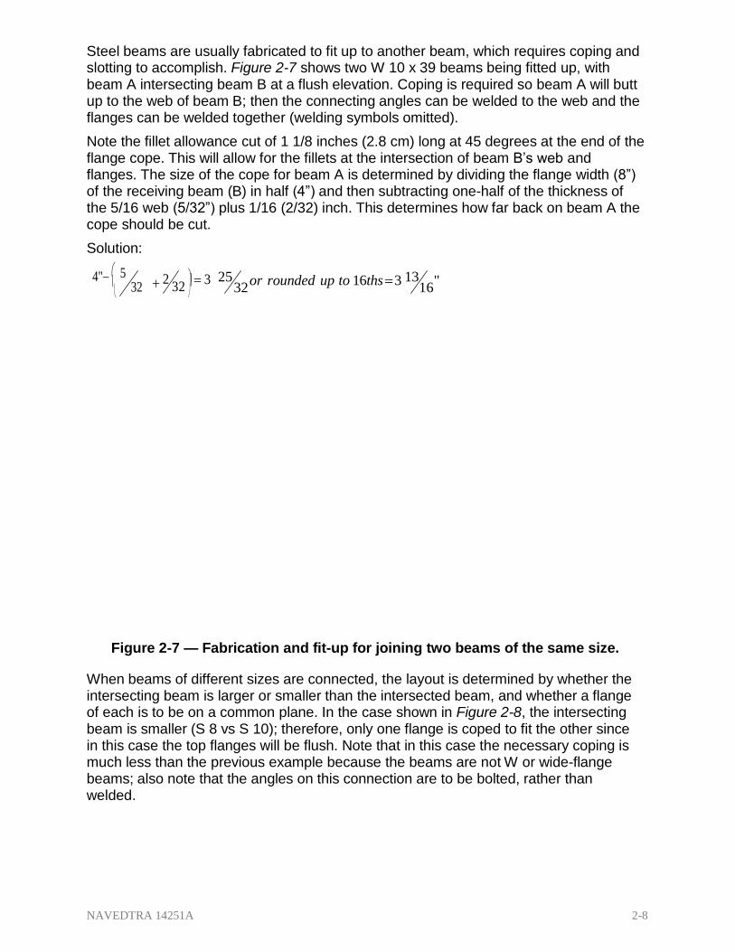
Steel beams are usually fabricated to fit up to another beam, which requires coping and slotting to accomplish. Figure 2-7 shows two W 10 x 39 beams being fitted up, with beam A intersecting beam B at a flush elevation. Coping is required so beam A will butt up to the web of beam B; then the connecting angles can be welded to the web and the flanges can be welded together (welding symbols omitted).
Note the fillet allowance cut of 1 1/8 inches (2.8 cm) long at 45 degrees at the end of the flange cope. This will allow for the fillets at the intersection of beam B’s web and flanges. The size of the cope for beam A is determined by dividing the flange width (8”) of the receiving beam (B) in half (4”) and then subtracting one-half of the thickness of the 5/16 web (5/32”) plus 1/16 (2/32) inch. This determines how far back on beam A the cope should be cut.
Solution:
4" 5
2
25 32
or rounded up to 16ths 3 16
"
Figure 2-7 — Fabrication and fit-up for joining two beams of the same size.
When beams of different sizes are connected, the layout is determined by whether the intersecting beam is larger or smaller than the intersected beam, and whether a flange of each is to be on a common plane. In the case shown in Figure 2-8, the intersecting beam is smaller (S 8 vs S 10); therefore, only one flange is coped to fit the other since in this case the top flanges will be flush. Note that in this case the necessary coping is much less than the previous example because the beams are not W or wide-flange beams; also note that the angles on this connection are to be bolted, rather than welded.

NAVEDTRA 14251A 2-9
Figure 2-8 — Typical framed construction, top flange flush.
1.3.1 Connection Angle Layout
The connection angle is a very common connection with framed construction (Figure 2- 9).
Figure 2-9 — Connection angle layout.
NAVEDTRA 14251A 2-10
The legs of the angles used as connections are specified according to the surface to which they are to be connected, and use distinct terminology:
Web legs — the legs of the angle that attach to the intersecting steel beam.
Outstanding legs — the legs of the angles that attach to the supporting or intersected steel beam.
Gauge lines — the lines in which holes in the angle legs are placed.
Gauges — the distances between gauge lines and known edges.
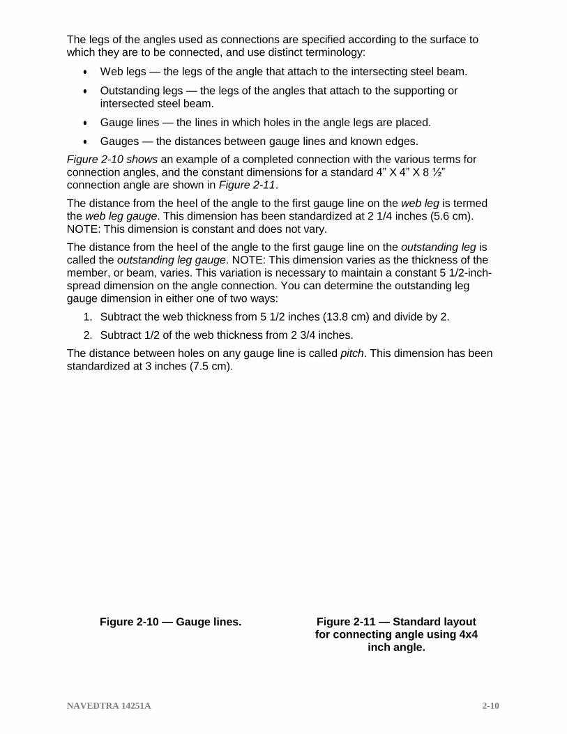
Figure 2-10 shows an example of a completed connection with the various terms for connection angles, and the constant dimensions for a standard 4” X 4” X 8 ½” connection angle are shown in Figure 2-11.
The distance from the heel of the angle to the first gauge line on the web leg is termed the web leg gauge. This dimension has been standardized at 2 1/4 inches (5.6 cm). NOTE: This dimension is constant and does not vary.
The distance from the heel of the angle to the first gauge line on the outstanding leg is called the outstanding leg gauge. NOTE: This dimension varies as the thickness of the member, or beam, varies. This variation is necessary to maintain a constant 5 1/2-inch- spread dimension on the angle connection. You can determine the outstanding leg gauge dimension in either one of two ways:
1. Subtract the web thickness from 5 1/2 inches (13.8 cm) and divide by 2.
2. Subtract 1/2 of the web thickness from 2 3/4 inches.
The distance between holes on any gauge line is called pitch. This dimension has been standardized at 3 inches (7.5 cm).
Figure 2-10 — Gauge lines. Figure 2-11 — Standard layout for connecting angle using 4x4
inch angle.

NAVEDTRA 14251A 2-11
The end distance is equal to one-half of the remainder left after subtracting the total of all pitch spaces from the length of the angle. By common practice, the angle length that is selected should give a 1 1/4-inch (3-cm) end distance.
This section cannot cover all layout and fabrication procedures, but some examples are shown in Figure 2-12. Notice that the layout and fabrication yard has a table designed to allow for layout, cutting, and welding with minimum movement of the structural members, and the stock materials are stored with like kinds of materials.
In addition, the fab table is holding two columns being fabricated out of beams with added baseplates and cap plates, as well as two angles that have already been coped, and there are angle clips for seated connections being installed before erection. Figure 2-13 shows a seated beam to column connection where the beam and column flanges are the same size.
Figure 2-12 — Prefab table and steel
storage.
Figure 2-13 — Seated connection.

NAVEDTRA 14251A 2-12
1.4.1 Cutting and Splicing Beams
As the fabricator, at times you will need to split a beam lengthwise to make a tee shape from an I shape, and you do this by splitting through the web. However, unless you carefully control the splitting process, the split parts will bend or warp from the release of internal stresses locked up in the beams during the manufacturer’s rolling process. Use the following procedure to cut and split a beam.
1. Cut the beam to the desired length.
2. Make splitting cuts about 2 feet (60 cm) long, leaving 2 inches (5 cm) of undisturbed metal between all cuts and at the end of the beam (Figure 2-14).
3. Cool the steel behind the torch with a water spray or wet burlap.
4. Allow the beam to cool.
5. Starting at the center of the beam and working toward the ends, cut through the metal between the cuts following the order shown in Figure 2-14.
This procedure also works very well when splitting plate and you should use it when making bars from plate. You can make multiple cuts from plate by staggering the splitting procedure before cutting the space between slits. If you use this procedure, be sure to cool the entire plate so the bars will not warp or bend.
Figure 2-14 — Cutting order for splitting a beam.

NAVEDTRA 14251A 2-13
1.5.1 Templates
When you need to produce a part in quantity, make a template first and lay out the job from the template. A template is any pattern made that is used as a guide for the work to be done; you can make it from sheet metal, regular template paper, wood, or any other suitable material. A template can be the exact size and shape of the corresponding piece (Figure 2-15, Views 1 and 2), or it may cover only the portions of the piece that contains holes or cuts (Figure 2-15, Views 3 and 4).
When you are going to make holes, cuts, and bends in a finished piece, the pilot holes, punch marks, and notches in the template must correspond exactly to the desired location in the finished piece. To make templates for short members and plates, use template paper of the same size as the piece to be fabricated. To make templates for angles, fold them longitudinally along the line of the heel of the angle (Figure 2-15, View 3).
Templates need specific attention and double-checking for accuracy, and often need to be held to closer tolerances than production models. Obviously, when you are going to produce a number of parts from a template, using inaccurate measurements to make the template will mean all parts produced from it will also be wrong, thus wasting time and resources.
Template paper is a heavy cardboard material with a waxed surface well adapted to scribe and divider marks. When size, dimensions, and planned reuse are appropriate, you can make a template from a combination of wood and template paper.
For long members, such as beams, columns, and truss members, your templates may cover only the connections joined by a wooden strip to ensure accurate spacing (Figure 2-15, Views 1 and 2). Alternatively, you can handle them separately, with the template for each connection being clamped to the member after spacing, aligning, and measuring along the production piece for the proper location.
Figure 2-15 — Paper and combination templates.

NAVEDTRA 14251A 2-14
To make the templates, use the same layout tools discussed in Steelworker Basic, Chapter 13, Layout and Fabrication of Sheet-Metal and Fiber and Glass Duct, except that for marking lines, you can use a pencil or Patternmaker’s knife on the template paper. Also, remember when you align punch holes in a template, the purpose of the holes is to specify the center location, not the size of the hole; therefore, you can use a single diameter punch for all holes. If necessary, make holes and cuts more prominent by marking them with paint.
Mark each template with the following information:
1. Item number of the stock material to be used in making the piece.
2. Description of the material.
3. Assembly mark of the piece it is to be used with.
When you lay out a production piece from a template, do the following:
1. Clamp the template to the material in the exact position.
2. Center punch the holes directly through the holes in the template (Figure 2-16).
3. Mark all cuts.
4. Remove the template.
5. Center punch the cut marks to make permanent rows.
Figure 2-16 — Use of template in laying out
a steel channel.

NAVEDTRA 14251A 2-15
In the fabrication area, many pieces can start to look similar; after all, they are usually made of the same stock materials. Therefore, each member or individual piece of material for a given project must be given identifying marks to correspond with marks shown on the detail drawing (Figure 2-17).
Assembly mark — a mark painted on each piece on completion of its layout so that the piece can be identified during fabrication and fit-up with other pieces to form a finished member such as a truss assembly.
Erection mark — a mark used to identify and locate it for erection at the job site. It is painted on the completed member at the left end, as shown on the detail drawing, and in a position so that it will be right side up when the member is right side up in the finished structure.
Various systems of erection markings can be used as long as all members of the project understand the system. The following are a few examples of erection marks:
C12 (2-4) C is the designation identifying a column
12 is the column number
(2-4) specifies the 2nd through the 4th floors
B3(4) B is the designation identifying a beam
3 is the beam number
(4) specifies the 4th floor

NAVEDTRA 14251A 2-16
Figure 2-17 — Erection and assembly marks.
2.1.1 PIPE FITTING
Do not let the lack of templates, charts, or mathematical formulas hinder your layout of pipe connections. In emergencies, you can quickly and easily lay out for welded pipe of equal diameter in the field by using the methods described here. With a few simple tools, you can lay out branches and Y connections as well as turns of any angle, radius, and number of segments.
Through almost daily use, a Steelworker is familiar with these readily available tools:
Framing square
o For this discussion, the long part of the framing square is referred to as the blade; the short part is referred to as the tongue.
Bevel protractor with a 12-inch (20-cm) blade
Spirit level
Spring steel wraparound (or tape)
o A stiff strip of cardboard or a tin sheet about 3 inches [7.5 cm] wide also makes a good wraparound.
Center punch
Hammer
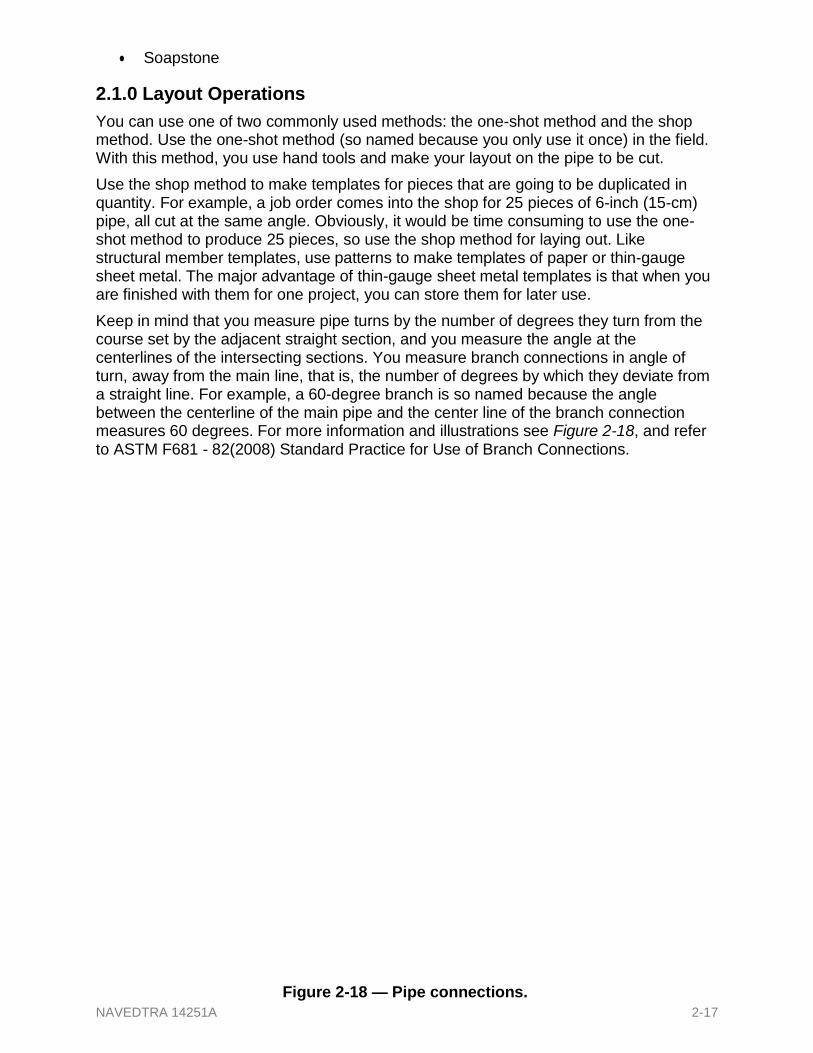
NAVEDTRA 14251A 2-17
Soapstone
2.1.0 Layout Operations
You can use one of two commonly used methods: the one-shot method and the shop method. Use the one-shot method (so named because you only use it once) in the field. With this method, you use hand tools and make your layout on the pipe to be cut.
Use the shop method to make templates for pieces that are going to be duplicated in quantity. For example, a job order comes into the shop for 25 pieces of 6-inch (15-cm) pipe, all cut at the same angle. Obviously, it would be time consuming to use the one- shot method to produce 25 pieces, so use the shop method for laying out. Like structural member templates, use patterns to make templates of paper or thin-gauge sheet metal. The major advantage of thin-gauge sheet metal templates is that when you are finished with them for one project, you can store them for later use.
Keep in mind that you measure pipe turns by the number of degrees they turn from the course set by the adjacent straight section, and you measure the angle at the centerlines of the intersecting sections. You measure branch connections in angle of turn, away from the main line, that is, the number of degrees by which they deviate from a straight line. For example, a 60-degree branch is so named because the angle between the centerline of the main pipe and the center line of the branch connection measures 60 degrees. For more information and illustrations see Figure 2-18, and refer to ASTM F681 - 82(2008) Standard Practice for Use of Branch Connections.
Figure 2-18 — Pipe connections.

NAVEDTRA 14251A 2-18
2.2.1 Quartering the Pipe
In laying out any joint, the first step is to establish reference points or lines from which you can make additional measurements or markings. Do this by locating a center line, then dividing the outside circumference of the pipe into 90-degree segments, or quarters.
Use the framing square, spirit level, and soapstone in the following manner:
Block the pipe so it cannot move or roll.
Place the inside angle of the square against the pipe and level one leg.
o One point on the centerline is then under the scale at a distance of one-half the outside diameter from the inside angle of the square (Figure 2-19).
Repeating at another part of the pipe will locate two points and hence the centerline.
o By this same method, you can locate the quarter points. This operation is a must before you begin any layout with the field method.
Figure 2-19 — Locating the top and side quarter points.

NAVEDTRA 14251A 2-19
If you are using a long piece of pipe and are going to cut both ends, to locate the top and the bottom centerlines, in addition to the square you will need a piece of carpenter’s chalk line with a plumb bob on each end and two 24- or 36-inch (60- or 90-cm) flat steel rules (depending on the diameter of the pipe). Figure 2- 20 shows plumb bobs and rules being used to locate the top and the bottom centerlines.
Another quicker one-shot method of quartering pipe is to take a strip of paper and wrap it around the pipe, then mark, tear, or cut the overlap. The marks or ends should touch. Remove the paper from the pipe and fold it in half (Figure 2-21, View A), then fold the doubled strip in half once again (Figure
Figure 2-20 — Locating the top and bottom
center lines.
2-21, View B). This will divide your strip into four equal parts. Now place the strip of paper around the pipe again, lap the original marks (or butt the ends), and your pipe will be quartered at the crease marks and where the ends meet for marking with soapstone.
Figure 2-21 — Folding a tip of
paper for use in quartering pipe.

NAVEDTRA 14251A 2-20
2.3.1 Template for Two-Piece Turn
Pipe with square ends can be fabricated by wrapping a rectangular section of plate into a cylindrical form. This fact makes available a method (known as parallel forms) of developing pipe surfaces, and hence developing the lines of intersection between pipe walls. Based on this principle, you can make wraparound templates for marking all manner of pipefittings for cutting preparatory to welding.
In practice, you develop a template by dividing the circumference (in the end view) of the pipe into a specific number of equal sections, then project these sections in parallel onto the side view of the desired pipe section. Following that, you lay out the lengths of the various segments that make up the pipe wall, evenly spaced, on a base line. This line is, in effect, the unwrapped circumference (Figure 2-22).
If you wrap the template developed in Figure 2-22, View C around a pipe with the base line square with the pipe, the curved line, a-b-c-d-e-f-, and so forth, will locate the position for cutting to make a 90-degree, two-piece turn. Use the following procedure to develop the template:
1. Figure 2-22, View A — Draw a circle equal to the outside diameter of the pipe.
2. Divide half of it into equal sections (the more sections, the more accurate the result).
3. Figure 2-22, View B — Perpendicular to the centerline and bisected by it, draw line a-i equal to the O.D.
4. To this line, construct the template angle (TA) equal to one-half of the angle of turn, or in this case, 45 degrees.
5. Draw lines parallel to the centerline from points a, b, c, and so forth, on the circle and mark the points where these lines intersect line a-i with corresponding letters.
Figure 2-22 — Principles of template layout.

NAVEDTRA 14251A 2-21
6. Figure 2-22, View C — As an extension of a-i but a little distance from it, draw a straight line equal to the pipe circumference (the circle in View A).
7. Divide this line into twice as many equal spaces as the semicircle, a-b-c-, and so forth, and letter as shown.
8. Project perpendiculars from these points.
9. Project horizontals from View B parallel to the base line in View C.
10. Their intersections determine the curve of the template. .
2.4.1 Simple Miter Turn
You can make a simple miter turn after quartering the pipe (Figure 2-23). First, locate the center of the cut (point c) in the general location where the cut is to be made, and then use a wraparound to make line a-b completely around the pipe at right angles to the center and quarter lines. This establishes a base line for further layout work.
Note: When you are measuring, treat the surface of the pipe as if it were a flat surface. Use a flat- steel rule or tape, which will lie against the surface without kinks, even though it is forced to follow the contour of the pipe. You can check these angles for
Figure 2-23 — Simple miter turn.
accuracy by sighting with the square.
Use the protractor and square to determine the proper cutback for the desired angle of the miter turn by using the following procedure:
1. Start with the protractor scale set at zero so the flat surface of the protractor and the blade are parallel.
2. Set the protractor for the number of degrees desired and lock the blade.
Figure 2-24 — Finding the cutback.

NAVEDTRA 14251A 2-22
3. Place the protractor on the square with the bottom blade on the outside diameter of the pipe (Figure 2-24).
4. Read up to the cutback on the vertical blade of the square.
5. Be sure the flat surface of the protractor is flush against the blade of the square. (The outside radius of the pipe should have been determined during the quartering operation).
6. After you have obtained the cutback measurement, mark one-half of this measurement off along the center line on top of the pipe.
7. From the opposite side of the base line, measure off the same distance along the bottom quarter line.
8. Make punch marks with the center punch on each side of the line along the side quarter lines. These marks will make it easy to align the pipe for welding after the joint is cut.
9. Use the spring steel wraparound and pull the loop to the cutback point.
10. Draw a chalk line over the top half of the pipe through the first cutback point. (NOTE: Do not allow the wraparound to twist or kink, and hold the chalk at a right angle to the wraparound while marking the pipe.)
11. Roll the pipe one-half turn and mark a chalk line in the same way around the bottom half of the pipe.
2.5.0 Two-Piece Turn
For the cut necessary for a two-piece welded turn of any angle between 1 and 90 degrees, if a template is not available you can determine the dimensions and markings by making a full-sized drawing, as shown in Figure 2-25.
Draw the centerlines intersecting at b by using the angle of turn T and then draw the outlines of the pipes by using the centerlines and their respective diameters D. These will intersect at a and c. By laying the pipe over the drawing so point b coincides with the angle determined by construction details, you can draw the lines a-b and c-b in preparation for miter cutting and beveling.
After being prepared for welding, one section of pipe should be rotated through 180 degrees to form the desired angle, and then it should be tack-welded. Spacing should be slightly greater at the inside of
the turn. Figure 2-25 — Locating a cut on a pipe for
any angle of a two-piece turn.

NAVEDTRA 14251A 2-23
2.6.1 Welded Tee
To lay out the template for cutting the branch and header of equal diameter for a 90- degree tee, draw the side and end view, as shown in Figure 2-26, Views A and B.
In making the template for the branch in Figure 2-26, use the following procedures:
1. View A — Draw lines 1-5 at 45 degrees to the centerline.
2. Lay off distance 1-P equal to twice the thickness of the pipe wall and draw the smooth curve s-P-s.
3. View B — Project point P from View A to View B and draw the lines P-t radially.
4. At a distance above point t equal to the thickness of the header wall, draw a-t horizontally, and vertical lines a-a, and t-t.
5. With lower points a as center, swing arcs r-s.
6. Using the intersections of these arcs as centers and with the same radius, draw the curved lines a-b-c-d-e and e-d-c-b-a.
7. Divide the outside circumference of the branch top into equal parts and draw the vertical lines b-b, c-c, and so forth.
8. View D — Draw the horizontal base line a-a.
9. Lay off the unwrapped circumference and divide each half into the same number of equal parts as the branch semi-circumference.
10. Plot the distances a-a, b-b, and so forth, from View B. This gives the distances from the base line to the branch curve of the intersection and determines the location of the branch template.
To make the template for the hole in the header in Figure 2-26, use the following procedures:
1. View B — Divide the circumference of the header into equal parts, as at points 1, 2, 3, and so forth.
2. View A — Project these points across to View A as shown.
3. View C — Lay off the line 1-5-1 equal to one-half the circumference of the header, and divide it into the same number of equal parts as was done on the header.
4. Locate point P, a distance from 1 equal to 1-P in View B.
5. With this point P and the distances 5-5, 4-4, and so forth, in View A, plotted as shown in View C, you have identified the curve of the template for the hole in the header.

NAVEDTRA 14251A 2-24
Figure 2-26 — 90° tee.

NAVEDTRA 14251A 2-25
2.7.1 Branch Connections
You can lay out templates for cutting branch-to-header connections of equal diameter at any angle of 45 to 90 degrees (Figure 2-27). Note: You can make templates with angles less than 45 degrees, but the difficulty of welding the crotch section imposes a practical limitation.
Use the following procedures to lay out the cut for the header:
1. Quarter both sections of pipe.
2. Locate the centerline of the intersection (point B) on the header.
3. Draw line GF around the pipe at this point.
4. Set the diameter FG on the blade of the square.
5. Set and lock the protractor at one-fourth of the number of degrees of turnaway from the header (in the example, 1/4 of 60° = 15°).
6. With the blade along FG, the first cutback measurement, FA, will be indicated on the tongue of the square.
7. Measure off this distance along the centerline of the header from line FG, and mark point A.
8. Join point A with the points of intersection of line FG and the two side quarter lines to outline the first cut.
9. With the same protractor setting, flip the square and mark point H. Distance FH is equal to FA. FH is the first portion of the second cutback measurement.
10. With the same settings and with the square upside down (as compared to before), locate point I the same way you located point H.
11. Set the protractor to one-half of the number of degrees of turnaway from the header (in the example, 1/2 of 60° = 30°).
12. With the blade set to the diameter, the second portion, HD, of the second cutback measurement will be indicated on the tongue. The second cutback measurement is the total distance FC.
13. Connect points C and B and connect C with the point, which corresponds to B, on the quarter line on the opposite side of the header. This outlines the second cut and completes the marking of the header.
Use the same two cutback measurements to
Figure 2-27 — Branch connections.

NAVEDTRA 14251A 2-26
lay out the end of the branch.
Branch cutback distance DA is equal to header cutback distance FA.
Branch cutback distance EC is equal to header cutback distance FC.
If the branch end is square, make cutback measurements from the end, rather than marking in a circumferential line.
Make all cuts as before; level and join the branch and header by welding.
2.8.0 Welded Tee (Branch Smaller Than the Header)
Where the branch is smaller than the header, you can obtain one of the best types of joints for a 90-degree branch connection by inserting the smaller branch pipe through the wall down to the inner surface of the header. This allows the outside surface of the branch to intersect the inside surface of the header at all points, and when the header is properly beveled, this type of intersection presents a very desirable vee for welding. Templates are always recommended, but in case templates or template dimensions are not available, you can locate the line of cut on both header and branch by other methods.
In the first method, you place the square end of the branch in the correct position against the header and mark the line of intersection with a flat soapstone pencil (Figure 2-28).
Since you will use radial cutting in this case, and since the outer branch wall should intersect the inner header wall, locate point B on both sides of the branch a distance from A equal to slightly more than the header wall thickness. Now mark a new line of cut as a smooth curve through the points, tapering to the first line at the top of the header and follow the radial cutting with a beveling cut.
Then slip the branch into the hole until even with point B to locate the line of cut on the branch for radial cutting; no beveling is necessary.
Figure 2-28 — Method where the line of cut is first marked on main.
Figure 2-29 shows a second method for larger diameter pipe. After you have drawn the centerlines, place the branch against the header, as shown. With a straightedge, determine the distance A between the branch and the header wall, and transfer this measurement to the branch wall, as represented by the curved line a-b-c.
After you have cut this line, use the branch to locate the line of cut on the header, allowing for the intersection of the outer branch wall and inner header wall as before. Then, radial cut this line on the header, and follow by beveling.

NAVEDTRA 14251A 2-27
If you need to make an eccentric branch connection in the extreme case where the side of the branch is even with the side of the header, use a similar procedure by projecting the cut location with a straightedge, as shown in Figure 2-30.
Figure 2-29 — Line of cut is first marked on
branch with this method.
Figure 2-30 — Marking cut on branch for
eccentric branch connection.
NAVEDTRA 14251A 2-28
2.9.1 Three-Piece Y Connection
The entire procedure for fabrication of an equal diameter, three-piece Y connection is based on the individual operations just described. As usual, the first step is to quarter the end of all three pieces of pipe and apply circumferential lines. When the three pieces are welded together to form the Y, there will be three centerlines radiating from a common point.
You must decide the open angle between each pair of adjacent centerlines, for each of these angles will be the angle of one of the branches of the Y. As shown in Figure 2-31, these open angles determine the angle of adjoining sides of adjacent branches. Thus, half of the number of degrees between centerlines A and B (90°) is included in each of the adjoining cutbacks between these two branches. The same is true with respect to the other angles and cutbacks between centerlines (B and G=160°as well as A and G=110°). Moreover, each piece of pipe must have a combination of two angles cut on the end.
To determine the amount of cutback to form an angle of the Y:
1. Set the protractor at one-half of the open angle between adjacent branch center lines.
2. Place the protractor on the square, crossing the outside radius measurement of the pipe on the tongue of the square, and read the cutback distance off the blade of the square.
3. Mark off this distance on one side quarter line on each of the two pieces that are to be joined.
4. Mark the cutback lines.
5. Repeat this procedure for the other two angles of the Y, taking care to combine the cutbacks on each pipe end. Three settings of the protractor determine all cutbacks.
An alternate method for determining each cutback is to treat two adjacent branches as a simple miter turn.
1. Subtract the number of degrees of open angle between centerlines from 180 degrees and set the protractor at one-half of the remaining degrees.
2. Cross the outside radius measurement on the tongue.
3. Mark one side of each adjoining pipe section.
4. Repeat for the other two branches. Take care to combine the proper cutbacks on each pipe end. Figure 2-31 — Three-piece Y connection.

NAVEDTRA 14251A 2-29
5. Set the protractor for each open angle of the Y connection.
The computations and measurements for the layout (Figure 2-31) are shown in Table 2- 1. The pipe is 12 inches in diameter and has a radius of 6 inches (15 cm).
Table 2-1 — Computations and Measurements for a Y Connection.
ACB ACG BCG
Open angle between center lines 90° 110° 160°
Protractor setting (half of each angle) 45° 55° 80°
Cutbacks 6” 4 1/8” 1 1/16”
Centerlines A B C
Paired cutback measurements (inches)
fe = 6”
cd = 4 1/8”
ab = 1 1/16”
fe = 6”
ab = 1 1/16”
cd = 4 1/8”
2.10.0 Layout of a True Y
In laying out pipe for the fabrication of a true Y without the use of templates or tables, you should make a full-sized drawing of the intersection (Figure 2-32). The intersection of the centerlines of the three pipes will locate point B, and lines from B to the intersections of the pipe walls will locate points A, C, and D. From these points, you can mark the pipe for miter cutting and suitable beveling to prepare it for welding.
Figure 2-32 — True Y.

NAVEDTRA 14251A 2-30
2.11.0 Template Layout for True Branches and Main Lines
In laying out a template for a true Y, make a drawing of the intersection, as shown in Figure 2-33, View A. After drawing the lines of intersection, follow the same essential methods used for other templates. Note: here it suggests that the equally divided semi- circumferences are more conveniently placed directly on the base line, and when you plot the distances from the base line to the line of intersection (View A, a-d-g) onto the unwrapped base lines [(View B a-d-g-d-a) and (View C g-d-a-d-g)x 2], it determines the template.
2.12.1 Orange Peel Head
Welded pipe construction uses a number of different types of heads. Here we are interested in one general type, the orange peel, since it will often concern you in your work. A main advantage of the orange peel is that it has high strength in resisting internal pressure.
If templates or tables are not available for making an orange peel head, you can still lay out a reasonably accurate template.
The number of arms to make an orange peel head should be the minimum number that you can easily bend over to form the head. Five arms and welds are the recommended minimum for any pipe, but you should increase this number for larger diameter pipes. Dividing the circumference by 5 is a good method for deciding the number of arms, provided there are at least 5.
To lay out the template, use the following procedures:
1. Draw the side and end views as shown in Figure 2-34, Views A and B.
2. Divide the pipe circumference in View B into the number of equal parts you plan to weld.
3. Draw the radial lines o-a, o-b, and so on.
4. Project the points a, b, and so on, in View B onto View A.
5. Divide x-o-x into equal parts, in this case, 6.
6. Draw the lines x1-x1 and x2-x2 in View A. These represent the concentric circles in View B. In laying out the template, the distances a-b, b-c, a1-b1, a2-b2, and so on, are taken from View B. The distances x-x1, x-x2, b-b1, and so on, are taken from View A.
7. All cutting should be radial followed by a beveling cut.
Actually, it is not necessary to draw Views A and B since you can determine all the values by a simple computation. Figure 2-35 shows a one-shot field method of making an orange peel when you are going to make only one, and it will help to line up your template better.

NAVEDTRA 14251A 2-31
Figure 2-33 — Template for true Y branches and main of equal diameter.

NAVEDTRA 14251A 2-32
Figure 2-34 — Orange peel head.
Figure 2-35 — A field method of making an orange peel.

NAVEDTRA 14251A 2-33
3.0.0 PIPE CUTTING
Cutting pipe is not much different from cutting structural shapes, except you must always keep in mind that the cut will be either radial or miter. Use a gas-cutting torch to cut pipe for welding. To review procedures for using a cutting torch, refer to Steelworker Basic, Chapter 4, Gas Cutting. The torch may be hand operated, or it may be mounted on a mechanical device for more accurate control.
Cutting machines are able to prepare many fittings without the use of templates. These machines cut and bevel the pipe in one operation, with the bevel extending for the full pipe wall thickness. When pipe is cut by hand, beveling is done as a second operation.
Many types of welded fittings require a radial cut before beveling. Radial cutting simply means the cutting torch is held perpendicular to the interior centerline at all times, in other words, the cutting orifice always forms a continuation of a radius of the pipe, making the cut edge square with the pipe wall at every point. Figure 2-36 shows radial cutting. Except in the case of the blunt bull plug, for which the radial cut provides the proper vee, you should always follow the radial cut with a beveling cut for pipe with 3/16-inch (4.8 mm) or more wall thickness.
Figure 2-36 — Radial cutting.
In miter cutting, you hold the torch tip so the entire cut surface is in the same plane. The miter cut is followed by a beveling cut, leaving a 1/32- to 1/16-inch (.8 to 1.6-mm) nose at the inner wall. Figure 2-37 shows miter cutting.

NAVEDTRA 14251A 2-34
Figure 2-37 — Miter cutting.
4.0.0 PIPE BENDING
Any piping system of consequence will have bends in it. When fabricating pipe for such a system, you can make bends by a variety of methods, either hot or cold, and either manually or on a power-bending machine. Cold bends in pipe are usually made on a bending machine, and various types of equipment are available, ranging from portable handsets to large hydraulically driven machines that can cold bend pipe up to 16 inches (40.64 cm) in diameter (Figure 2-38). You will be concerned primarily with hot bending techniques, using a bending slab, or using a method known as wrinkle bending.

NAVEDTRA 14251A 2-35
Figure 2-38 — Types of pipe benders.

NAVEDTRA 14251A 2-36
4.1.0 Templates
Whatever method you use to bend pipe, you should normally have some pattern that represents the desired shape of the bend. Templates made from wire or small, flexible tubing can be invaluable in preparing new installations as well as in repair work. When properly made, they will provide an exact guide to the bend desired.
The centerline template is one simple type of bend template. It is made to conform to the bend or bends of the pipe being made, and is used to lay off the bend area on the pipe as well as a guide during the pipe or tube bending operation. Figure 2-39 shows the use of a centerline template. You make these templates out of wire or rod, and shape them to establish the centerline of the pipe to be installed. You secure the ends of the wire to special clamps called flange spiders, and add clearance discs the same diameter as the pipe if there is any doubt about the clearance around the pipe.
Figure 2-39 — Center line template.

NAVEDTRA 14251A 2-37
4.2.1 Hot Bends
You can make hot bends on a bending slab, which requires little maintenance beyond a light coating of machine oil to keep rust in check (Figure 2-40). Use the following procedures:
1. Pack the pipe with dry sand to prevent the heel or outside of the bend from flattening. If flattening occurs, it will reduce the cross-sectional area of the pipe and restrict the flow of fluid through the system.
2. Drive a tapered, wooden plug into one end of the pipe.
3. Place the pipe in a vertical position with the plugged end down.
4. Fill it with dry sand.
Figure 2-40 — Bending on a slab.
Leave just enough space at the upper end to take a second plug.
To ensure that the sand is tightly packed, tap the pipe continually with a wooden or rawhide mallet during the filling operation.
The second plug is identical to the first, except for a small vent hole drilled through its length to vent any gases (mostly steam) that may form in the packed pipe when you apply heat.
No matter how dry the sand may appear, there is always a possibility that some moisture is present. This moisture will form steam that will expand and build up pressure in the heated pipe unless you provide
Figure 2-41 — Heating and bending pipe to
conform to a wire template.

NAVEDTRA 14251A 2-38
some means of escape. If you do not provide a vent, you will almost certainly blow out one of the plugs before you get the pipe bent.
5. Heat the pipe and make the bend.
6. Mark the bend area of the pipe with chalk or soapstone, and heat it to an even red heat along the distance indicated from A to B in Figure 2-41.
7. Apply heat to the bend area, first on the outside of the bend, then on the inside. When you have obtained an even heat, bend the pipe to conform to the wire template. Use the template also to mark the bend area on the pipe.
Exert the pull to make the bend in a direction parallel to the surface of the bending slab. You can gain the necessary leverage for forming the bend by using chain falls, block and tackle, or another length of pipe large enough to slip over the end of the packed pipe. Use bending pins and hold-down clamps (dogs) to position the bend at the desired location.
Be sure to wear the proper gloves when working on hot bending jobs. Often, you must remove pins, clamps, and baffles during the bending operation, and these items absorb heat radiated from the pipe as well as from the torch flame. You cannot safely handle these bending accessories without proper gloves.
The main problem you will have in bending copper tubing and pipe is preventing wrinkles and flat spots. Wrinkles are caused by compression of the pipe wall at the throat (inside) of the bend. Flat spots are caused by lack of support for the pipe wall, by stretch in the heel (outside) of the bend, or by improper heating.
If you properly pack and heat the pipe, you can prevent wrinkles and flat spots by bending the pipe in segments so the stretch is spread evenly over the whole bend area. When you bend a pipe, the stretch tends to occur at the middle of the bend. If you divide the bend area into segments, and bend in segments, the stretch will occur at the center of each segment and thus spread more evenly over the bend area. Another advantage of bending in segments is that this is almost the only way you can follow a wire template accurately.
When you bend steel and some other piping materials, you can control wrinkles and flat spots by slightly overbending the pipe and then pulling the end back (Figure 2-42).
Figure 2-42 — Overbending to correct flattening of pipe.
Each material has its peculiar traits, and you need to know about these traits to get satisfactory results. The following hints for bending different materials should prove helpful:

NAVEDTRA 14251A 2-39
Wrought iron — Wrought iron becomes brittle when hot, so always use a large bend radius. Apply the torch to the throat of the bend instead of to the heel.
Brass — Do not overbend; brass is likely to break when the bend direction is reversed.
Copper — You can make hot bends on copper, but the copper alloys are more adaptable to cold bending. This material is one that is not likely to give any trouble.
Aluminum — Overbending and reverse bending do not harm aluminum, but because there is only a small range between the bending and melting temperature, you will have to work with care. Keep the heat in the throat at all times. You will not be able to see any heat color, so you must depend on “feel” to tell you when the heat is right for bending. You can do this by keeping a strain on the pipe while the bend area is being heated. As soon as the bend starts, flick the flame away from the area. Play it back and forth to both maintain the bending temperature and avoid overheating.
Carbon-molybdenum and chromium-molybdenum — If necessary, you can heat these for bending, but exercise caution to not overheat the bend area. These types of metal easily crystallize when you apply extreme heat. You should cold bend pipes made from these materials in manual or power-bending machines.
4.3.0 Wrinkle Bends
After just describing precautions necessary to keep a bend free of wrinkles, it may seem odd to next describe a method that deliberately produces wrinkles as a means of bending the pipe. Nevertheless, you will find the wrinkle-bending technique a simple and direct method of bending pipe, and perhaps in many pipe-bending situations, the only convenient method. This would particularly be the case if no bending slab were available or if time considerations did not permit the rather lengthy sand-packing process.
Wrinkle bending consists of a simple heating operation in which you heat a section of the pipe on the inside of the bend with a gas-welding torch. When the metal becomes plastic (bright red color), you slightly bend the pipe, either by hand or by tackle rigged for that purpose. The unheated portion forms the heel (outside) of the bend, while the wrinkle forms at the throat (inside) of the bend due to compression.

NAVEDTRA 14251A 2-40
To avoid buckling the pipe, do not bend it through very large angles (12 degrees is the maximum for one wrinkle).To make a large bend, make several small wrinkles one at a time instead. If, for example, you want to produce a bend of 90 degrees, make a minimum of eight separate wrinkles of about 12 degrees (8 X 12° = 96°). Figure 2-43 shows a 90-degree bend made with ten separate wrinkles. To determine the number of wrinkles, divide the degrees per wrinkle required into the degrees of the bend required.
Wrinkle bending has been successful on pipe of more than 20 inches in diameter. Experience has shown that, for 7-inch diameter pipe and over, you can accomplish more complete and even heating by using two welding
Figure 2-43 — 90° bend made with ten
separate wrinkles.
torches rather than one. In any event, the heating procedure is the same; use the torch or torches to heat a strip approximately two thirds of the circumference of the pipe (Figure 2-44). The heated strip need not be very wide (2 to 3 inches, or 5.08 to 7.62 cm, is usually sufficient) since the bend will only be through 12 degrees at most. As already noted, the heated portion is the part that will compress to become the inside of the bend; the portion not heated directly will form the outside of the bend.
The technique most often used to bend the pipe once it has been heated is simple and straightforward. The pipe is merely lifted up by gloved hand (or by tackle), while the other end is held firmly in position.
Figure 2-44 — Part of pipe heated before
wrinkle bending.

NAVEDTRA 14251A 2-41
Summary
This chapter discussed how to lay out and fabricate steel plate and structural steel members. Information was also provided on pipe layout and fabrication, along with specific instructions on pipe cutting, fitting, and bending. As always, use the manufacturer’s operator manuals for the specific setup and safety procedures of the equipment you will be using, and wear the proper personal protective equipment.

NAVEDTRA 14251A 2-42
Review Questions (Select the Correct Response) 1. When laying out a plate with many parts, you must consider which factor?
A. Time required B. Economic use of material C. Type of material used D. All of the above
2. A job has been laid out and is determined to be accurate. At this time, what
modification should be made to all cutting lines?
A. Cut them with a torch on the inside of the kerf. B. Center punch, then cut them with the kerf on the outside edge of the
reference lines. C. Transfer to patterns before cutting them so the work can be checked after
cutting. D. Lightly paint them to preserve the layout lines.
3. (True or False) Structural shapes are more difficult to lay out than plate because
the reference lines are not always visible.
A. True B. False
4. When two beams of equal dimensions are fitted together, coping is required so
one will butt up against the web of the other. You can determine the size of cope needed by dividing the flange width by .
A. 1/8, then adding 1/16 inch B. 1/2, then subtracting 1/2 of the thickness of the web and adding 1/16 inch C. 1/4, then adding 1/8 inch D. 1/2, then adding 1/2 of the thickness of the web and subtracting 1/16 inch
5. (True or False) Outstanding legs are the legs of the angles that attach the
supporting angle or intersected steel beam.
A. True B. False
6. The lines in which holes in the angle legs are drilled are known as what type of
lines?
A. Dimension B. Layout C. Gauge D. Drill

NAVEDTRA 14251A 2-43
7. On what part of a connection angle does the distance from the heel of the angle to the first gauge line remain constant?
A. Web leg gauge B. Outstanding leg C. Gauge line D. Top flange
8. The standard 3-inch distance between the holes on any gauge line is known
as_ .
A. leg gauge B. pitch C. web leg gauge D. dimension angle
9. When using templates to help lay out a steel member, you should make sure the
identifying marks on the templates and the member correspond to which plans or drawings?
A. Erection B. Detail C. Flat D. Field
10. What information does the erection mark on a member provide?
A. Location and orientation of the member during erection B. Date of fabrication C. Sequence of erection D. Erection completion date
11. (True or False) To fabricate 25 pieces of pipe of the same diameter and layout
dimensions, you should use the shop method of making templates.
A. True B. False
12. When quartering a pipe before proceeding to lay out a joint, you should place the
inside angle of the framing square against the pipe after taking what action?
A. Leveling one leg of the framing square. B. Blocking one leg of the framing square. C. Blocking the pipe. D. Leveling the pipe.
13. What is the first step in developing a template layout for pipe?
A. Drawing a circle equal to the outside diameter of the pipe. B. Constructing the template angle equal to twice the angle of the turn. C. Dividing the circumference of the projected view by one-half. D. Bisecting the template angle.

NAVEDTRA 14251A 2-44
14. In making a simple miter turn, what step do you perform after determining the cutback measurement?
A. Measure one-half of the distance to the cutback on the vertical plane. B. Mark one-half of the cutback measurement along the centerline on top of
the pipe. C. Lock the protractor blade. D. Determine the outside radius of the pipe.
15. In what position should the protractor be locked to show the number of degrees
of turnaway from the header to fabricate a branch-to-header connection of equal diameter pipe?
A. At an angle equal to the degree of turnaway B. At half of the angle of turnaway C. At one-third of the angle of turnaway D. At one-fourth of the angle of turnaway
16. In fabricating a three-piece connection of equal diameter pipe, for what reason
must you decide upon the size of the open angle between each pair of centerlines?
A. To determine the position of the centerlines. B. To determine the angle of the adjoining sides of adjacent branches. C. To quarter the ends of the three pieces of pipe. D. To apply circumferential lines to each piece of pipe.
17. When cutting a pipe with a hand torch, what type of cutting process do you use to
hold the cutting torch perpendicular to the interior centerline of the pipe at every point?
A. Miter B. Radial C. Reverse D. Concentric
18. What are the flange spiders of a centerline template made of wire used for in
pipe bending?
A. To clamp the ends of the wire. B. To maintain a constant clearance around the pipe. C. To indicate pipe clearance. D. To indicate the centerline of the pipe.
19. Before heating a pipe, what action should you take to prevent a reduction in the
cross-section area of a hot-bend pipe?
A. Pack it with wet sand. B. Pack it with dry sand. C. Pack it with wet packing. D. None

NAVEDTRA 14251A 2-45
20. Flat spots in hot-bent copper pipe are caused by which factor?
A. Improper heating B. Not enough support for the pipe wall C. Stretch in the outside (heel) of the bend D. All of the above
21. The use of which bending technique should prevent wrinkles and flat spots in
properly packed and heated copper pipe?
A. Bending so all the stretch takes place at the center of the bend area, none on the ends.
B. Bending so all the stretch takes place at the ends of the bend area, none at the center.
C. Bending so more of the stretch takes place at the center of the bend area than at the other end.
D. Dividing the bend area into segments, then bending one segment at a time so stretching is evenly spread over the entire area.
22. (True or False) In bending steel pipe, you can control wrinkles and flat spots at
the throat of a bend by overbending then pulling the end back to round out the flat spot.
A. True B. False
23. Pipe made of what material is likely to break if overbent and then pulled back?
A. Steel B. Brass C. Copper D. Aluminum
24. In hot bending aluminum pipe with a torch, you should use which technique?
A. Flick the flame away and back on the throat while the pipe is being bent. B. Heat only the throat of the bend and avoid overheating. C. Notice changes in heat color to determine the proper bending
temperature. D. Overheat then remove heat when bending starts.
25. When using the wrinkle-bending technique to make a 60-degree bend in a pipe,
you should make a total of how many wrinkles to keep from buckling the pipe?
A. One or two B. Two or three C. Three or four D. Five or more

NAVEDTRA 14251A 2-46
26. What technique should you use to wrinkle-bend a 12-inch-diameter pipe?
A. With one torch, heat a strip about 2 feet long and 2 to 3 inches wide along the throat of the planned bend.
B. With one torch, heat a strip about 2 feet long and 2 to 3 inches wide along the heel of the planned bend.
C. With more than one torch, heat a strip about 2 feet long and 2 to 3 inches wide along the throat of the planned bend.
D. With more than one torch, heat a strip about 2/3 of the circumference of the pipe, and 2 to 3 inches wide along the throat of the planned bend.
27. What technique should you use when bending a heated pipe?
A. While holding one end of the pipe firmly in position, lift the other end. B. While holding the midpoint of the pipe on the ground, lift both ends at the
same time. C. While holding the midpoint of the pipe on the ground, lift one end then the
other. D. None

NAVEDTRA 14251A 2-47
Trade Terms Introduced in this Chapter
Kerf The width of a groove made by a cutting tool.

NAVEDTRA 14251A 2-48
Additional Resources and References
This chapter is intended to present thorough resources for task training. The following reference works are suggested for further study. This is optional material for continued education rather than for task training.
Frankland, Thomas, W., The Pipefitter's and Pipe Welder’s Handbook, Glencoe/McGraw-Hill Publishing Company, Woodland Hills, CA, 1984.
Frankland, Thomas, W., Pipe Trades Pocket Manual, Glencoe/McGraw-Hill Publishing Company, Peoria, IL, 1969.
Nelson, Carl, A., Millwright’s and Mechanic's Guide, 2d ed., Theodore Audel and Company, Indianapolis, IN, 1972.
The Oxy-Acetylene Handbook, 2nd ed., Linde Company, New York NY, 1960.
Walker, John, R., Modern Metalworking, Goodheart-Wilcox Company Inc., South
Holland, IL, 1973.

NAVEDTRA 14251A 2-49
CSFE Nonresident Training Course – User Update
CSFE makes every effort to keep their manuals up-to-date and free of technical errors. We appreciate your help in this process. If you have an idea for improving this manual, or if you find an error, a typographical mistake, or an inaccuracy in CSFE manuals, please write or email us, using this form or a photocopy. Be sure to include the exact chapter number, topic, detailed description, and correction, if applicable. Your input will be brought to the attention of the Technical Review Committee. Thank you for your assistance.
Write: CSFE N7A 3502 Goodspeed St. Port Hueneme, CA 93130
FAX: 805/982-5508
E- mail: [email protected]
Rate_ Course Name
Revision Date Chapter Number Page Number(s)
Description
(Optional) Correction
(Optional) Your Name and Address

NAVEDTRA 14251A 3-1
Chapter 3
Fabrication and Placement of Reinforcing Steel
Topics
1.0.0 Bending Reinforcing Bars
2.0.0 Placing and Tying Reinforcing Steel
To hear audio, click on the box.
Overview
In recent years, increased concerns about security have refocused the attention of military architects and designers on the elements of structural design and structural integrity. An integral part of increasing building resistance to blasts is the proper use and placement of reinforcing steel.
As a Steelworker, you must be able to properly cut, bend, place, and tie reinforcing steel. This chapter describes the purpose of using reinforcing steel in concrete construction, the shapes of reinforcing steel commonly used, and the techniques and tools used by Steelworkers in rebar (reinforcing steel) work.
Objectives
When you have completed this chapter, you will be able to do the following:
1. Describe the procedures associated with bending reinforcing bars.
2. Describe the procedures for placing and tying reinforcing steel.
Prerequisites
None

NAVEDTRA 14251A 3-2
This course map shows all of the chapters in Steelworker Advanced. The suggested training order begins at the bottom and proceeds up. Skill levels increase as you advance on the course map.
Welding Costs
S
T
E
E
L
W
O
R
K
E
R
A
D
V
A
N
C
E
D
Metal Fence System
Fabrication and Placement of Reinforcing Steel
Layout and Fabrication of Structural Steel and Pipe
Properties and Uses of Metal
Features of this Manual
This manual has several features that make it easy to use online.
Figure and table numbers in the text are italicized. The Figure or table is either next to or below the text that refers to it.
The first time a glossary term appears in the text, it is bold and italicized. When your cursor crosses over that word or phrase, a popup box displays with the appropriate definition.
Audio and video clips are included in the text, with an italicized instruction telling you where to click to activate it.

NAVEDTRA 14251A 3-3
Review questions that apply to a section are listed under the Test Your Knowledge banner at the end of the section. Select the answer you choose. If the answer is correct, you will be taken to the next section heading. If the answer is incorrect, you will be taken to the area in the chapter where the information is for review. When you have completed your review, select anywhere in that area to return to the review question. Try to answer the question again.
Review questions are included at the end of this chapter. Select the answer you choose. If the answer is correct, you will be taken to the next question. If the answer is incorrect, you will be taken to the area in the chapter where the information is for review. When you have completed your review, select anywhere in that area to return to the review question. Try to answer the question again.

NAVEDTRA 14251A 3-4
1.0.0 BENDING REINFORCING BARS
Reinforcing bars often need bending (fabrication) into various shapes to accommodate the stresses in the project’s design. Remember, the reason for using reinforcing steel in concrete is to increase the tensile strength of concrete, since concrete’s strength is primarily compressive strength.
Compare the hidden action within a beam to breaking a stick over your knee. As you apply force (compression) and your knee pushes toward the middle on one side of the stick, the splinters on the opposite side pull away (tension) from the middle. This is similar to what happens inside a beam.
For illustration, take a simple beam resting freely on two supports near its ends as in Figure 3-1. The dead load (weight of the beam itself) causes the beam to bend or sag.
Figure 3-1 — Loading a beam.

NAVEDTRA 14251A 3-5
Any additional non-permanent load (live load) increases the loading stress (compression) at the top of the beam. From the center of the beam to the bottom of the beam, the forces tend to stretch or lengthen laterally. This part is in tension, and that is where the beam needs the greatest reinforcement.
With the combination of concrete and steel, the tensile strength in the beam resists the force of the loads and keeps the beam from breaking apart. At the exact center of the beam’s depth, between the compressive stress and the tensile stress, there is no stress at all—it is neutral (Figure 3-2).
Figure 3-2 — Steel reinforcement in a concrete beam.
In the case of a continuous beam, it is a little different. The top of the beam may be in compression (between columns) along part of its length and in tension along another part (at columns). This is because a continuous beam rests on more than two supports. Thus, the bending of the beam is NOT all in one direction but reversed as it goes over intermediate supports.
To help the concrete resist these stresses, engineers design the bends of reinforcing steel so installers will maximize the placement of additional rebar where the tensile stresses take place. That is why some rebar bends are in an almost zigzag (truss) pattern. Figure 3-3 shows a standard rebar bending schedule with some typical rebar bends you will encounter. Types, 3, 4, 5, 6, 7, 22, and 23 are all versions of truss bars.

NAVEDTRA 14251A 3-6
Figure 3-3 — Typical rebar bends.

NAVEDTRA 14251A 3-7
The drawings for a job provide all the information necessary for cutting and bending reinforcing bars. Reinforcing steel can be cut to size with shears or with an oxygas cutting torch, and you can also use the cutting torch in the field to make any necessary on-site field adjustments.
If you are fabricating in the field at the jobsite, before bending the reinforcing bars, check and sort for quantity and sizes to be sure you have all you need for the job. Follow the construction drawings when you sort the bars so they will be in the proper order to be bent and placed in the concrete forms. After you have divided the different sizes into piles, label each pile so that you and your crew can find them easily.
You can use a number of types of benders for the job of bending, often just called fabricating, or “fabbing the rebar.” Stirrups and column ties are normally No. 3 or No. 4 bar, and you can bend them cold by means of the bending table shown in Figure 3-4. Figure 3-5 shows typical stirrup tie shapes for the stirrups used in beams, shown in Figure 3-6. Figure 3-7 shows column ties in position on a preassembled column prior to setting.
Figure 3-4 — Bending table. Figure 3-5 — Stirrup tie shapes.
Figure 3-6 — Stirrups in a beam. Figure 3-7 — Column ties.
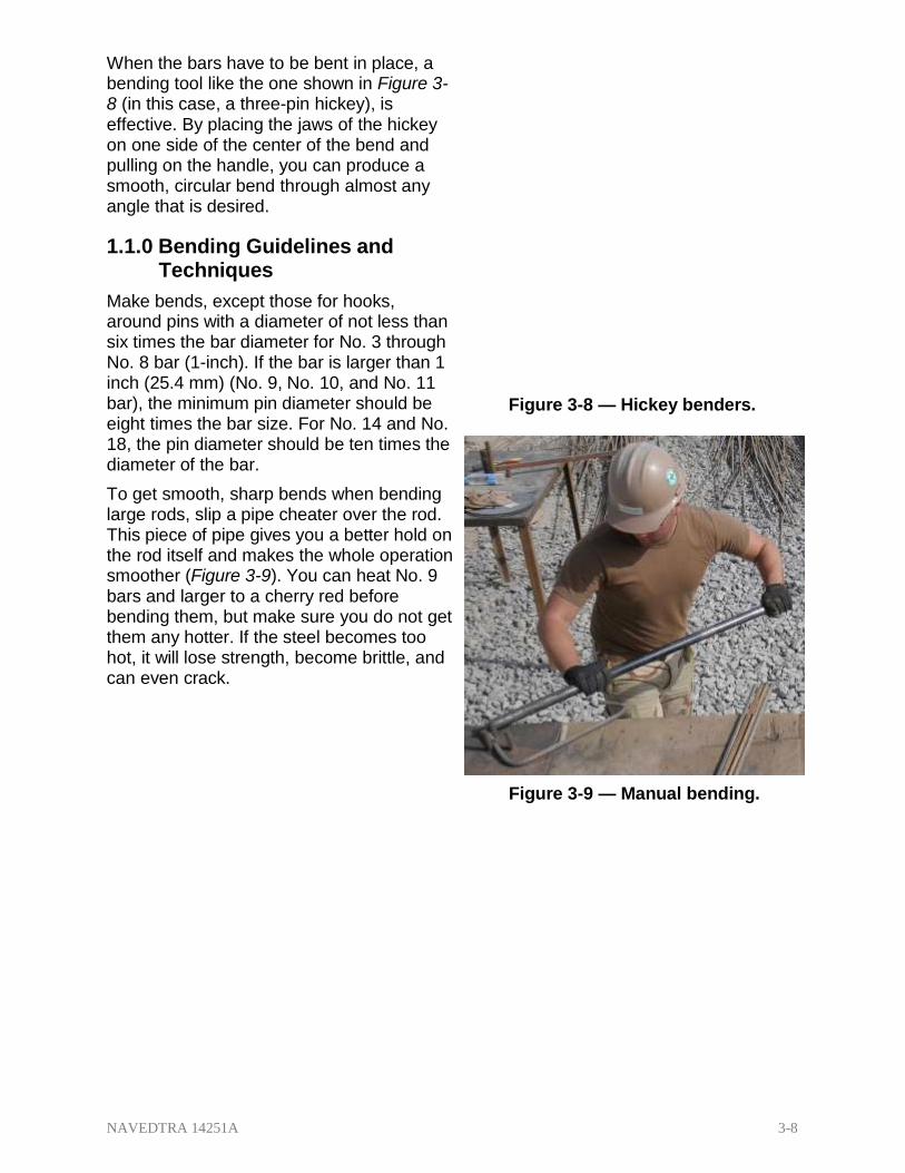
NAVEDTRA 14251A 3-8
When the bars have to be bent in place, a bending tool like the one shown in Figure 3- 8 (in this case, a three-pin hickey), is effective. By placing the jaws of the hickey on one side of the center of the bend and pulling on the handle, you can produce a smooth, circular bend through almost any angle that is desired.
1.1.0 Bending Guidelines and Techniques
Make bends, except those for hooks, around pins with a diameter of not less than six times the bar diameter for No. 3 through No. 8 bar (1-inch). If the bar is larger than 1 inch (25.4 mm) (No. 9, No. 10, and No. 11 bar), the minimum pin diameter should be eight times the bar size. For No. 14 and No. 18, the pin diameter should be ten times the diameter of the bar.
To get smooth, sharp bends when bending large rods, slip a pipe cheater over the rod. This piece of pipe gives you a better hold on the rod itself and makes the whole operation smoother (Figure 3-9). You can heat No. 9 bars and larger to a cherry red before bending them, but make sure you do not get them any hotter. If the steel becomes too hot, it will lose strength, become brittle, and can even crack.
Figure 3-8 — Hickey benders.
Figure 3-9 — Manual bending.

NAVEDTRA 14251A 3-9
1.2.0 Bend Diameters
When bending reinforcing bars, benders in the field or fabricators in the shop must exercise caution to ensure the bends are not too sharp. Rebar may crack or weaken if bent too sharply. The American Concrete Institute (ACI 318 Building Code Requirements for Structural Concrete) has established minimum bend diameters for the different bar sizes and for the various types of hooks.
There are many different types of bends, depending on how the rods are to be used. For example, there are hooks for the ends of heavy beams and girders, offset bends for vertical column splices at or near floor levels, beam stirrups, column ties, slab reinforcement, and spiral for round columns or foundation caissons. These bending details are shown in Figure 3-10.
Figure 3-10 — Multiple bends and bending details.
To save yourself some time and extra work, try to make all bends of one kind at one time instead of continuously measuring and setting the templates on your bending block for different bends.

NAVEDTRA 14251A 3-10
1.3.0 Reinforcing Steel (RST) Bending and Cutting Equipment
RST bending and cutting equipment ranges from a simple leverage bar to a 10,000- pound electro-hydraulic rebar fabricator capable of bending and cutting # 18 rebar. As a Steelworker, you will normally be bending rebar in the field. Most of the tools you will be working with will be portable. The following are some of the tools and machines you may be using in the field.
Leverage bar — also known as a hickey, this bar is comprised of a long handle and a jaw mechanism to hold on to the rebar and impart a bend in it.
Manual cutter and bender —normally attached to a length of 2 x 6, it has a leverage bar and a rebar cutter. The rebar cutter head is very similar to a bolt cutter (Figure 3-11).
On some small projects, such as minor building foundations, curb installations, or similar jobs with minimal but necessary rebar requirements, often contractors will use the combination cutting and bending tool like the one shown.
Figure 3-11 — Manual cutter and bender.
A hand-held electric/hydraulic bender and cutter (Figure 3-12) and hand-held chop saw (Figure 3-13) are used for in-place bending and cutting rebar.
Figure 3-12 — Hand-held cutter and bender.
Figure 3-13 — Hand-held chop saw.

NAVEDTRA 14251A 3-11
A portable table rebar cutter and bender is used for high volume repetitious bends before the rebar is placed into the concrete (Figure 3-14). It has a lever or knob type of angle selector for consistent bends.
1.4.0 Standard Hook Bending
Using an electric or hydraulic rebar bender to bend reinforced steel bars can save you a lot of time and physical effort during the construction process. Learning how to use a rebar bender can be an easy process once you follow a few simple instructions and follow some key safety guidelines.
Rebar bending machines come in a variety of pressure output specifications and bending angle capabilities. Make sure that you choose the correct bender for the thickness of the rebar you are trying to
Figure 3-14 — Table cutter and bender.
bend and the angle you need to achieve. If you have an electrically powered bender, make sure you have the correct electrical connections available for the machine. Bender operation is typically conducted through easy-to-use foot pedals that ensure that you have both hands free to manipulate the rebar during the bending process. Foot pedals also enable you to step away from the machine and halt operation instantly in case of emergencies.
Most common bending machines will come with a variety of bending rollers. Be sure you use the correct set to meet the thickness of the rebar you are going to bend, and use the adjustment knob to adjust the bending angle for the angle desired. The adjustment knobs can typically manipulate rebar from angles of 1 degree to 180 degrees or more.
Always wear protective gloves while handling the rebar. After you have put on your gloves, lift the rebar and place it into the feeding slot of the machine. Note that some machines allow you to bend multiple pieces of rebar simultaneously. However, if you are using the machine for the first time, start with one bar at a time to gain familiarity with the machine’s operation, and prevent alignment and handling issues. Use a firm grip on the rebar and stand in a position that allows you to quickly move away from the machine in case of a safety concern.
The foot pedals will allow you to activate the machine once the rebar is in place. On certain models, an electronic interlocking system may not allow you to activate the machine until certain safety prerequisites are met.
The hydraulic mechanism will engage and start the bending process. You need to be very alert at this point to ensure that your hand is placed out of harm’s reach as the roller bends the rebar.
Once the bending process has ended, keep clear of the foot pedals and remove the rebar from the machine. In many cases, you may need to add a second bend to the same rebar, in which case you can repeat the process as desired.

NAVEDTRA 14251A 3-12
Your speed and efficiency of using the bender will improve as you practice using the machine a few times.
1.5.0 Multiple Bending
Bending multiple reinforcement bars is accomplished the same way as standard hook bending, simply by placing the bars in the machine one on top of the other (Figure 3- 15). The size limitations of the rebar will be stated in the operator’s manual. Do not exceed the rated capacity of the machine, or possible personal injury or damage to the machine may occur.
2.1.1 PLACING and TYING REINFORCING STEEL
Before you place rebar in a form, ensure the form oiling has already been done. Oiling the form after the rebar is in place may allow some of the oil to get on the rebar, which will
Figure 3-15 — Multiple bars.
interfere with the concrete bonding process. Use a piece of burlap to remove rust, loose mill scale, grease, mud, or other foreign matter from the bars. However, a light film of rust or mill scale is acceptable and in fact preferable.
During the bending process, you need to mark the reinforcing bars to indicate where they will be located in the project and fit into a particular assembly. You may work according to either one of the two most often used systems for marking bars; however, the system you use needs to agree with the marking system on the engineering or assembly drawings. The two marking systems used are as follows:
1. All bars in one type of member are given the mark of that member. This system is used for column bars, beam bars, footing bars, and so on.
2. The bars are marked in greater detail. These marks show exactly where the bar is to be placed. In addition to the type member (that is, beam (B), wall (W), column (C), and so on), the marks show the floor on which the bars are to be placed and the size and individual number of each particular bar. Instead of showing the bar size by its diameter measurement, the mark shows the bar size in code by eighths. The examples shown below show the second type of marking system.
Tag 2B805
o 2 = second floor
o B = beam member
o 8 = 8/8- or 1-inch (2.5 cm)-square bar
o 05 = part of the second floor plan designated by the number 5
Tag 2B0605
o 2 = second floor
o B = beam member

NAVEDTRA 14251A 3-13
o 06 = 6/8- or 3/4-inch (1.9 cm)-round bar
o 05 = part of second floor plan designated by the number 5
2.1.0 Types of Ties
Tie wire is used to hold rebar in place to ensure that when concrete is placed the bars do not shift out of position. Typically, 16-gauge wire is used to tie reinforcing bars, although in the civilian industries 15-gauge wire is commonly used and on rare occasion 14-gauge wire is used for special circumstances. About 12 pounds (5.4 kg) of 16-gauge wire is required to tie an average ton (0.9 tonne) of bars.
NOTE
Tie wire adds nothing to the strength of the steel. The tie wire may come in large rolls (shoulder coils) where installers cut smaller sections off and roll it around the neck and shoulders as they use the wire. However, in today’s civilian industry where Ironworkers place the rebar, tie wire reels affixed to belts are the common method of distributing the wire. On small projects when only snap ties are necessary, another alternative is looped end tie wires (Figure 3-16).
Figure 3-16 — Wire ties and tools.

NAVEDTRA 14251A 3-14
Installers use a number of different tie configurations to join rebar together and hold it in the proper spacing and in place as the concrete pours. Each has its particular situational use, such as for speed, climbing, or twist prevention. Figure 3-17 shows six types of ties; below, they are identified according to the letters of the alphabet with characteristics identifying their particular use.
A. Snap tie or simple tie. The wire is simply wrapped once around the two crossing bars in a diagonal manner with the two ends on top. These are twisted together with a pair of sidecutters until they are very tight against the bars. Then the loose ends of the wire are cut off. This tie is used mostly on floor slabs.
Figure 3-17 — Types of ties.
B. Snap tie with a round turn or wall tie. This tie is made by going about 1 1/2 times around the vertical bar, then diagonally around the intersection, twisting the two ends together until the connection is tight, but without breaking the tie wire, then cutting off the excess. The wall tie is used on light vertical mats of steel.
C. Double-strand simple tie. This tie is a variation of the simple tie. It is especially favored for heavy work.
D. Saddle or U tie. The wires pass halfway around one of the bars on either side of the crossing bar and are brought squarely or diagonally around the crossing bar with the ends twisted together and cut off. This tie is used on special locations, such as on walls.
E. Saddle or U tie with a twist. This tie is a variation of the saddle tie. The tie wire is carried completely around one of the bars, then squarely across and halfway

NAVEDTRA 14251A 3-15
around the other, either side of the crossing bars, and finally brought together and twisted either squarely or diagonally across. The saddle tie with twist is used for heavy mats that are to be lifted by a crane.
F. Cross tie or figure eight tie. This type of tie has the advantage of causing little or no twist in the bars.
Figure 3-18 — Slab reinforcement bar supports.
The proper location for the reinforcing bars is usually given on drawings. In order for the structure to withstand the loads it must carry, the steel must be placed as shown in the drawings. Secure the bars in position in such a way that concrete-placing operations will not move them. This can be accomplished by the use of the reinforcing bar supports shown in Figures 3-18 (chairs and bolsters), 3-19 (concrete blocks or “dobies”), and 3- 20 (tie wire and temporary supports).

NAVEDTRA 14251A 3-16
Figure 3-19 — Ties using concrete block.
Figure 3-20 — Ties in a wooden form.

Figure 3-21 — Minimum coverage of rebar in concrete. NAVEDTRA 14251A 3-17
2.2.1 Minimum Concrete Coverage
The proper coverage of bars in the concrete is very important to protect the bars from fire hazards, possibility of corrosion, and exposure to weather. The American Concrete Institute’s ACI 318 publication Building Code Requirements for Structural Concrete and Commentary provides standards for minimal concrete coverage. When unspecified, follow the minimum standards given below and in Figure 3-21.
1. Footings — 3 inches at the sides and on the bottoms of footings or other principal structural members where concrete is deposited on the ground.
2. Walls — 2 inches for bars larger than No. 5, where concrete surfaces, after removal of forms, would be exposed to the weather or be in contact with the ground; 1 1/2 inches for No. 5 bars and smaller; 3/4 inch from the faces of all walls not exposed directly to the ground or the weather.
3. Columns — 1 1/2 inches over spirals and ties.
4. Beams and girders — 1 1/2 inches to the nearest bars on the top, bottom, and sides.
5. Joists and slabs — 3/4 inch on the top, bottom, and sides of joists and on the top and the bottom of slabs where concrete surfaces are not exposed directly to the ground or the weather.
NOTE
All measurements are from the outside of the bar to the face of the concrete, NOT from the main steel, unless otherwise specified.

NAVEDTRA 14251A 3-18
Reinforcing bars are in tension and therefore should never be bent around an inside corner. They can pull straight through the concrete cover. Instead, they should overlap and extend to the far face for anchorage with 180-degree hooks and proper concrete coverage (Figure 3-22).
Splices are sometimes needed to complete a reinforcement project. Where splices in reinforcing steel are not dimensioned on the drawings, the bars should be lapped not less than 30 times the bar diameter nor less than 12 inches (Table 3-1). The stress in a tension bar can be transmitted through the concrete and into another adjoining bar by a lap splice of
Figure 3-22 — Correct and incorrect
placement.
proper length. If you cannot lap the splices, you need to use mechanical butt splices.
NOTE
Lap splicing is prohibited in reinforcement bars sizes #14 and #18. Adhere strictly to the ACI 318 Building Code in all matters of reinforcement bar splicing.
Table 3-1 — Length of Lap Splices in Reinforcing Bars.
INCHES OF LAP CORRESPONDING TO NUMBER OF BAR DIAMETERS*
Number of
Diameters
Size of Bars
#3 #4 #5 #6 #7 #8 #9 #10 #11 #14 #18
30 12 15 19 23 27 30 34 39 43 Prohibited by
ACI 318 32 12 16 20 24 28 32 36 41 45
34 13 17 22 26 30 34 39 44 48
36 14 18 23 27 32 36 41 46 51
38 15 19 24 29 34 38 43 49 54
40 15 20 25 30 35 40 46 51 57
Minimum lap equals 12 inches!
* Figured to the next larger whole inch

NAVEDTRA 14251A 3-19
If you are authorized to use lap splices, consider the following guidelines:
1. Grade of steel: the higher the yield stress, the greater the lap length.
2. Surface condition of the bar: epoxy-coated bars require up to 50% longer laps than black bars.
3. Size of the bars: the larger the bar, the longer the lap.
4. Grade of concrete: the lower the concrete strength, the longer the lap required.
5. Location of the splice: efficiency is dependent on bar location, position in the structural member, edge conditions, and spacing.
6. Design load: the lap length required for bars in tension is much longer than for the same size bars in compression. A lap design for compression load will not perform as a full tension splice. In the event of unanticipated forces to a structure, lap splices may fail.
To lap WWF (weld wire fabric/wire mesh), you can use a number of methods, two of which are the end lap and the side lap. In the end lap method, the wire mesh is lapped by overlapping one full mesh, measured from the ends of the longitudinal wires in one piece to the ends of the longitudinal wires in the adjacent piece, and then tying the two pieces at 1-foot 6-inch (45.0 cm) centers with a snap tie. This method saves some material, but costs in time and labor since the corners of the squares do not meet and require additional tying. In the side lap method, the two longitudinal side wires are placed one alongside and overlapping the other and then are tied with a snap tie every 3 feet (.9 m). In this method, the corners of the squares always overlap and align, thus requiring less tying and lowering labor production time and costs.
You can splice reinforcing bars by metal arc welding, but only if called for in the plans and specifications, and you use a welder certified to weld rebar. For bars placed in a vertical position, a butt weld is preferred. The end of the bottom bar is cut square, and the end of the top bar resting on it is cut in a bevel fashion, thus permitting a butt weld. For bars that will bear a load in a horizontal position, a fillet weld is preferred. Usually, the two bars are placed end to end with pieces of flat bar (or angle iron) placed on either side. Fillet welds are then made where the metals join. The welds are made to a depth of one-half of the bar diameter and for a length eight times the bar diameter.
Unless you are lapping bars, you need to maintain distances between bars to achieve the designed concrete bonding. The minimum clear distance between parallel bars in beams, footings, walls, and floor slabs should be either 1 inch (25.4 mm) or 1 1/3 times the largest size aggregate particle in the concrete, whichever distance is greater. In columns, the clear distance between parallel bars should be not less than 1 1/2 times the bar diameter or 1 1/2 times the maximum size of the coarse aggregate; always use the larger of the two.
The support for reinforcing steel in floor slabs is shown in Figure 3-23. The required concrete protective cover determines the height of the slab bolster. Concrete blocks made of sand-cement mortar can be used in place of the slab bolster unless the plans and specs prohibit it for architectural reasons; never use wood blocks. You can obtain highchairs (Figure 3-18) in heights up to 6 inches (15 cm), or when a height greater than 6 inches is required, you can make the chair out of No. 0, soft, annealed iron wire. To hold the bars firmly in position, tie the bars with a snap tie at frequent intervals where they cross.

NAVEDTRA 14251A 3-20
Figure 3-23 — Floor slab reinforcement bar placement.
You can pre-assemble the rebar for columns by tying the vertical bars and ties into cages by laying the vertical bars for one side of the column horizontally across a couple of sawhorses. Then place and tie the proper number of ties at the spacing required by the plans and add the remaining vertical bars. Tie wire all intersections together to make the assembly rigid so that it can be hoisted and set as a unit. Figure 3-24 shows a typical column tie assembly set in place and spliced to the lower floor’s dowels.
Figure 3-24 — Reinforcement bar column.

NAVEDTRA 14251A 3-21
After the column is raised, it is tied to the dowels or reinforcing steel carried up from below. This holds it firmly in position at the base. Typically, concrete blocks (dobies) are tied to the column to maintain clearances, and the column form is erected and set in place. If dobies are not available and the rebar column is relatively light, it can be tied to the column form at 5-foot (4.5-m) intervals, as shown in Figure 3-25. The trouble with the latter system is the wires protruding from the forms. They must be watched and removed after the concrete is poured but before it sets, or removed after the form is stripped, thus leaving the ends exposed to promote rust.
Refer again to Figure 3-6 for the use of metal supports to hold beam reinforcing in position. Note the position of the beam bolster. The stirrups are tied to the main reinforcing steel with a snap tie. However, while the beam schedule may require only the bars that are illustrated (three in the bottom with the upper bars unplaced yet), practical experience will quickly demonstrate that there is nothing to keep the stirrups from falling over. Often the installer will add a “giveaway” bar, usually a #4, up the side of the stirrups but below bottom slab height, just to keep them in place with their tops at a common elevation. Wherever possible, assemble the stirrups and main reinforcing steel outside the form, and then place the assembled unit in position. Precast concrete blocks or
Figure 3-25 — Method of holding
column steel on plane in formwork.
plastic spacers, as shown in Figure 3-18, may be substituted for metal supports.
Figure 3-26 — Reinforcement steel on a wall
form.
Steel in place on a wall is shown in Figure 3-26. The wood block is removed when the form has been filled up to the level of the block. For high walls, ties in between the top and bottom should be used (Figure 3-27).

NAVEDTRA 14251A 3-22
The horizontal and vertical bars are wired securely to each other at sufficiently frequent intervals to make a rigid mat. Tying is required at every second or third intersection, depending upon the size and spacing of bars, but with not less than three ties to any one bar, and, in any case, not more than 4 to 6 feet apart in either direction.
Figure 3-27 — Reinforcement steel supports
in a wall.
Rebar is placed in footings very much as it is placed in floor slabs. Typically, dobies, rather than steel supports, are used to support the steel at the proper distance above the subgrade. Rebar mats in small footings (Figure 3-28) are generally preassembled and placed after the forms have been set, while mats in large footings (Figure 3-29) are constructed in place.
Figure 3-28 — Reinforcement steel in a slab.

NAVEDTRA 14251A 3-23
Summary
Figure 3-29 — Large floor slab.
This chapter discussed how to properly cut, bend, place, and tie reinforcing steel. It also described the purpose of using reinforcing steel in concrete construction, the shapes of reinforcing steel commonly used, and the techniques and tools used by steelworkers in rebar (reinforcing steel) work. As always, use the manufacturer’s operator manuals for the specific setup and safety procedures of the equipment you will be using, and wear the proper personal protective equipment.

NAVEDTRA 14251A 3-24
Review Questions (Select the Correct Response) 1. What does dead load refer to when describing stress on a beam?
A. External force applied by the columns B. Weight of the beam C. Transverse tension applied by the reinforcing bars D. Compression caused by a load
2. Where is the compression zone on a horizontally positioned beam resting on two
columns?
A. Ends of the beam B. Bottom of the center of the beam C. Top of the center of the beam D. Center of the beam
3. What size pin diameter, in inches, is required when a bend is made on a #9 bar?
A. 8 1/2
B. 9
C. 11 1/4
D. 18
4. What tie is most often used in floor slabs?
A. Saddle B. Double strand C. Wall D. Snap
5. What type of tie is made by going completely around one of the bars, then
squarely or diagonally around the crossing bar with the ends twisted together and cut off?
A. Double-strand single strand B. Saddle tie with a twist C. Figure eight tie D. Saddle tie
6. What tie will cause the least amount of twisting action on rebar?
A. Cross B. Saddle C. Snap D. Wall

NAVEDTRA 14251A 3-25
7. In concrete, proper coverage of the bars is required to prevent what condition(s) from developing?
A. Fire, weather, and corrosion damage B. Bars expanding and breaking through the concrete C. Rust forming on the reinforcement bars D. Loss of tensile strength in the bars
8. In footings between the ground and steel, what minimum thickness of concrete,
in inches, should be provided?
A. 3
B. 4
C. 6
D. 8
9. When splicing 1/2-inch-thick rebar of reinforcing steel without the benefit of drawing specifications, what is the minimum distance, in inches, that you should lap the bar?
A. 12
B. 15
C. 20
D. 25
10. What is the minimum number of wire ties per intersection?
A. 2
B. 3
C. 4
D. 5

NAVEDTRA 14251A 3-26
Trade Terms Introduced in this Chapter
None

NAVEDTRA 14251A 3-27
Additional Resources and References
This chapter is intended to present thorough resources for task training. The following reference works are suggested for further study. This is optional material for continued education rather than for task training.
ACI 318-05 Building Code Requirements for Reinforced Concrete, American Concrete Institute, Detroit MI, 2004.
Concrete Construction Engineering, 2nd ed. Nawy, E.G. Boca Raton, FL, 2008
Concrete and Masonry, FM 5-428, Headquarters Department of the Army, Washington, DC, 1998.
Consolidated Cross-Reference, TA-13, Department of the Navy, Navy Facilities Engineering Command, Alexandria, VA, 1989.
Construction Print Reading in the Field, TM 5-704, Headquarters Department of the Army, Washington, DC, 1969.
Placing Reinforcing Bars, 8th ed., Concrete Reinforcing Steel Institute, Schaumburg, IL, 2005.

NAVEDTRA 14251A 3-28
CSFE Nonresident Training Course – User Update
CSFE makes every effort to keep their manuals up-to-date and free of technical errors. We appreciate your help in this process. If you have an idea for improving this manual, or if you find an error, a typographical mistake, or an inaccuracy in CSFE manuals, please write or email us, using this form or a photocopy. Be sure to include the exact chapter number, topic, detailed description, and correction, if applicable. Your input will be brought to the attention of the Technical Review Committee. Thank you for your assistance.
Write: CSFE N7A 3502 Goodspeed St. Port Hueneme, CA 93130
FAX: 805/982-5508
E-mail: [email protected]
Rate Course Name
Revision Date Chapter Number Page Number(s)
Description
(Optional) Correction
(Optional) Your Name and Address

NAVEDTRA 14251A 4-1
1.0.0 Layout
2.0.0 Terminal
3.0.0 Line Pos
4.0.0 Terminal
5.0.0 Top Rail
6.0.0 Tension
7.0.0 Hanging
8.0.0 Stretchin
9.0.0 Fabric Ti
10.0.0 Gates
Chapter 4
Metal Fence Systems
Topics
Posts
ts
Post Fittings
s
Wires
Fence Fabric
g Fence Fabric
es
To hear audio, click on the box.
Overview
As a steelworker you will be involved in setting up different types of fencing from reinforced seven-foot, barbed-wire topped security fencing around an armory to a light residential baseball field fence. Because of the differences in the specifications for setting up these varied fences, we will only discuss the basic installation for a chain link fence, but once you know the basics, you will become a valuable asset to any fence project with another skill in your personal tool kit.
This chapter will discuss the layout procedures for terminal and line posts, as well as the assembly and hanging of the fence fabric. It will also discuss terminal post fittings, top rails, tension wires, and how to stretch fence fabric. The chapter concludes with fabric ties and installing single and double gates.

NAVEDTRA 14251A 4-2
Objectives
When you have completed this chapter, you will be able to do the following:
1. Identify the properties of metal and metal alloys.
2. Describe the layout of metal fencing systems.
3. Describe the installation of terminal posts.
4. Describe the installation of line posts.
5. Describe the installation of terminal post fittings.
6. Describe the installation of top rails.
7. Describe the installation of tension wires.
8. Describe the procedure of hanging fence fabric.
9. Describe the procedure of stretching fence fabric.
10. Describe the installation of fabric ties.
11. Describe the installation of gates.
Prerequisites
None

NAVEDTRA 14251A 4-3
This course map shows all of the chapters in Steelworker Advanced. The suggested training order begins at the bottom and proceeds up. Skill levels increase as you advance on the course map.
Welding Costs
S
T
E
E
L
W
O
R
K
E
R
A
D
V
A
N
C
E
D
Metal Fence Systems
Fabrication and Placement of Reinforcing Steel
Layout and Fabrication of Structural Steel and Pipe
Properties and Uses of Metal

NAVEDTRA 14251A 4-4
Features of this Manual
This manual has several features that make it easy to use online.
Figure and table numbers in the text are italicized. The Figure or table is either next to or below the text that refers to it.
The first time a glossary term appears in the text, it is bold and italicized. When your cursor crosses over that word or phrase, a popup box displays with the appropriate definition.
Audio and video clips are included in the text, with an italicized instruction telling you where to click to activate it.
Review questions that apply to a section are listed under the Test Your Knowledge banner at the end of the section. Select the answer you choose. If the answer is correct, you will be taken to the next section heading. If the answer is incorrect, you will be taken to the area in the chapter where the information is for review. When you have completed your review, select anywhere in that area to return to the review question. Try to answer the question again.
Review questions are included at the end of this chapter. Select the answer you choose. If the answer is correct, you will be taken to the next question. If the answer is incorrect, you will be taken to the area in the chapter where the information is for review. When you have completed your review, select anywhere in that area to return to the review question. Try to answer the question again.

NAVEDTRA 14251A 4-5
1.1.1 LAYOUT
The first step to any fence project is the layout. This will give you all the information you need to order the material to complete the job.
You may or may not be given a set of plans to erect the fencing; however, you will need to determine the perimeter of the project, and locate any underground lines or pipes to prevent digging or drilling mishaps.
Installation for the fence line, terminal posts, and gates will vary depending on the security level required, site conditions, geographical location, soil conditions, and weather conditions. The best documents to assist you in this process are ASTM-F567, "Standard Practice for Installation of Chain Link Fence", and the MIL-HNBK-1013/10 “Design Guidelines for Security Fencing, Gates, Barriers, and Guard Facilities”.
Once you determine the perimeter, drive stakes a foot or two away from where you will locate the corner posts; this will allow you to drill or dig holes without obstructions (Figure 4-1). It will also allow you to 'drop' the string while excavating for holes. Be careful not to bump or move stakes. If you remove the string to excavate holes, take care to restring the line back the way it was prior to removal.
Figure 4-1 — Layout of fence perimeter.

NAVEDTRA 14251A 4-6
You may want to create a right angle somewhere in your fence line. You can calculate this right angle by using the Pythagorean Theory (for mathematicians),
or by what is also called the 3-4-5 method (for construction application) (Figure 4-2):
1. Stake the spot where your fence will start.
2. Tie a string to the stake and stretch it out roughly parallel to the stake.
3. Measure 4 feet out on the string and mark it.
4. Tie another string to your second stake and stretch it out roughly perpendicular to the first string.
5. Mark a point 3 feet away from the stake.
6. Hold a tape measure diagonally between the three foot mark and the four-foot mark on the string, and move one of the strings until the distance between the marks is exactly 5 feet.
7. Adjust either one of the string lines as necessary to place the fence in the desired direction, and tie it down to this spot. The string lines are now exactly perpendicular. This works because 32 x 42 = 52 or 9 + 16 = 25.
Figure 4-2 — 3-4-5 method.

NAVEDTRA 14251A 4-7
You can use this method for greater accuracy over longer distances as well, just double or treble up the numbers, for example 6-8-10 (36 + 64 = 100) , or 9-12-15 (81 + 144 = 225).
Tie the string tight between the stakes. This string will represent the location of the fence and serve as a guide string as you set posts. Posts will be set in concrete or driven a measured distance from the string line so the work does not interfere with the straight edge line the string provides.
Long stretches of fence require intermediate stakes to eliminate sagging, and windblown curves. Be sure to pull the string taut, since a string that sags or moves with the wind will cause posts to be set incorrectly. Keep in mind, the fence can only be as straight as the guide string.
2.0.0 TERMINAL POSTS
While exact post depth will be determined by local weather and soil conditions, holes for terminal posts (end, corner, and gate) are generally dug three times (usually 8”-10” wide) the post diameter (terminal posts are typically larger diameter than line posts), and 30" deep with vertical sides (the hole should not slope, but be slightly wider at the bottom). If available, use a power auger to dig all postholes (Figure 4-3).
Figure 4-3 — Power auger.
Next, with crayon or chalk, mark the ground line on the posts so once in place, the terminal posts will be the height of the fence fabric plus 2". Terminal posts should be set 2" higher than the height of the fence fabric and line posts 2" lower than the height of the fence fabric (terminal posts should be 4" higher than the line posts).
NAVEDTRA 14251A 4-8
Set posts in concrete with the following mix: 1 part cement, 2 parts sand and 4 parts gravel. Mix a thick solution because too much water weakens concrete and may cause cracking. Posts should be centered in the hole (Figure 4-4). Be sure the crayon or chalk mark remains at ground level. Check the plumb with a carpenter’s level. When plumb, crown all concrete post footings for water drainage by sloping concrete away from post.
Figure 4-4 — Terminal Post.
3.0.0 LINE POSTS
After concrete footings have hardened enough for terminal posts to remain plumb (usually about 24 hours), stretch a piece of nylon string from the base of one terminal post to the base of the other. You want the string to be on the side you are going to have the chain link fabric on, usually the outside of the yard.
You will need to determine the actual distance of the section to be marked (for example, use 52' as the distance between terminal posts). Divide the distance by 10 and round your answer down to the next whole number. This is the required number of line posts. Example: 52' ÷ 10= 5.2. Round down to 5. You will need 5 line posts for this section. If you place 5 line posts in between these 2 terminal posts, it will yield 6 sections of fence. Maximum recommended distance between line posts is ten feet.
To determine the proper, equidistant spacing of line posts, divide the number of sections into the total distance. Example: 52' ÷ 6= 8.66 feet, or 8' 8".
CAUTION
When you arrive at a decimal answer like .66 feet, remember that you are working in 12 inch increments, so .66 feet is NOT rounded up to 7 inches, you must multiply .66 x 12 inches. Another way to remember is that .66 is equivalent to 2/3rds, and 2/3rds of a foot (12 inches) is 8 inches. See Table 4-1 for line post distances.

NAVEDTRA 14251A 4-9
Table 4-1 — Line post spacing chart.
Space Between Terminal Posts
Set Line Posts Apart
Space Between Terminal Posts
Set Line Posts Apart
30 ft 10 ft 76 ft 9 ft 6 in 31 ft 7 ft 9 in 77 ft 9 ft 7 in 32 ft 8 ft 78 ft 9 ft 9 in 33 ft 8 ft 3 in 79 ft 9 ft 10 in 34 ft 8 ft 6 in 80 ft 10 ft 35 ft 8 ft 9 in 81 ft 9 ft 36 ft 9 ft 82 ft 9 ft 1 in 37 ft 9 ft 3 in 83 ft 9 ft 3 in 38 ft 9 ft 6 in 84 ft 9 ft 4 in 39 ft 9 ft 9 in 85 ft 9 ft 6 in 40 ft 10 ft 86 ft 9 ft 7 in 41 ft 8 ft 2 in 87 ft 9 ft 8 in 42 ft 8 ft 5 in 88 ft 9 ft 9 in 43 ft 8 ft 6 in 89 ft 9 ft 10 in 44 ft 8 ft 9 in 90 ft 9 ft 45 ft 9 ft 91 ft 9 ft 2 in 46 ft 9 ft 2 in 92 ft 9 ft 2 in 47 ft 9 ft 5 in 93 ft 9 ft 3 in 48 ft 9 ft 7 in 94 ft 9 ft 5 in 49 ft 9 ft 9 in 95 ft 9 ft 6 in 50 ft 10 ft 96 ft 9 ft 7 in 51 ft 8 ft 6 in 97 ft 9 ft 7 in 52 ft 8 ft 8 in 98 ft 9 ft 8 in 53 ft 8 ft 10 in 99 ft 9 ft 9 in 54 ft 9 ft 100 ft 10 ft 55 ft 8 ft 2 in 101 ft 9 ft 2 in 56 ft 9 ft 4 in 102 ft 9 ft 3 in 57 ft 9 ft 6 in 103 ft 9 ft 4 in 58 ft 9 ft 8 in 104 ft 9 ft 5 in 59 ft 9 ft 10 in 105 ft 9 ft 6 in 60 ft 10 ft 106 ft 9 ft 7 in 61 ft 8 ft 8 in 107 ft 9 ft 8 in 62 ft 8 ft 10 in 108 ft 9 ft 9 in 63 ft 9 ft 109 ft 9 ft 10 in 64 ft 9 ft 110 ft 10 ft 65 ft 9 ft 3 in 111 ft 9 ft 3 in 66 ft 9 ft 5 in 112 ft 9 ft 4 in 67 ft 9 ft 7 in 113 ft 9 ft 5 in 68 ft 9 ft 8 in 114 ft 9 ft 6 in 69 ft 9 ft 10 in 115 ft 9 ft 7 in 70 ft 10 ft 116 ft 9 ft 8 in 71 ft 8 ft 9 in 117 ft 9 ft 9 in 72 ft 9 ft 118 ft 9 ft 10 in 73 ft 9 ft 2 in 119 ft 9 ft 10 in 74 ft 9 ft 3 in 120 ft 10 ft 75 ft 9 ft 4 in 121 ft 9 ft 3 in

NAVEDTRA 14251A 4-10
Using this nylon string and spacing method above, mark the location of the line posts, remove the string to get it out of the way of the auger or post hole digging tools, and dig the line postholes, usually 6"-8” wide, and 18" – 24" deep.
Note: If the line posts you are supplied with are the same length as your terminal posts, you will need to shorten them, or dig the line post holes 4-inches deeper (34”) than the terminal posts that will require additional labor and concrete materials.
Restring the line near the ground on the side of the posts that the fence fabric will be on, and insert a small spacer between the string and the post; for discussion purposes use a 1/4-inch spacer. Set another similar string line at the top of the terminal posts, 4” from the top with a 1/4-inch spacer on the fence fabric side, and use it as a reference line for the top of your line posts.
Install line posts so the fabric face of the line posts line up with the fabric face of the terminal post. This means the outside faces of the line posts will be about 1/4" inside the string line, and the top of the line post should be even with the string (Figure 4-5). While regularly checking side plumb with a level, set the line posts using concrete as described in step 2. Crown the footings like you did to the terminal posts.
Figure 4-5 — Setting line posts.

NAVEDTRA 14251A 4-11
4.0.0 TERMINAL POST FITTINGS
After concrete footings sufficiently harden, slip the tension bands evenly onto the terminal posts. Rule of thumb is to use one less tension band than the height of the fence fabric, for example 3 bands for a 4 foot fence, 4 bands for a 5 foot fence and so on. The long flat surface of the tension band should face toward the outside of the fence. Next, add rail end bands. Take care not to spread or distort the fittings. Ensure, all bolt heads for bands are on the outside of fence and the threaded ends are on the inside. Now apply all post caps to terminal posts (Figure 4-6).
Figure 4-6 — Terminal post fittings.

NAVEDTRA 14251A 4-12
5.0.0 TOP RAILS
Place eye-top, also called loop cap, (Figure 4-7) fitting on the end of each line post. The flat side of the eye-top should be toward the outside of the fence. Some loop caps lean in one direction, install these loop caps with the lean toward the outside of the fence. Slide top rail through a couple loop caps and butt the end firmly into the rail end cup on the 1-piece terminal post cap. If you have the 3-piece terminal post cap (dome cap, brace band & rail end cup), adjust height of rail end cup if necessary.
Figure 4-7 — Top rail fittings.
Some top rails are the same diameter on both ends and some are swedged. If you are using the top rail with both ends the same diameter you must use a rail sleeve to join the two pipes together. If you are using a swedged top rail, first, fit the nonswedged end into the rail end cup at the end or corner posts. Add sections of rail, sliding each non- swedged end onto a swedged end. Be certain to push rails toward your beginning point to 'seat' them all the way into each other by pushing firmly.
Cut excess rail off with hacksaw or pipe cutter. Mark the cut-off point carefully so the rail will fit snugly into the rail end cup. Any slack in your entire length of rail will allow the chain link, when stretched tight, to pull the end posts in towards each other.
Install the top rail in all stretches of fence. Visually check the height of line posts. If you followed the guidance in topic three, and did not allow the post to settle further in the wet concrete, all post should be at the proper height. However, if a post is too high, remove the rail and cap, and trim as necessary. If a post is 1/4" too short, you may also cut a sliver of pipe, the same diameter size as the line post and slip it under the loop cap. Secure rail end cup in place with a carriage bolt.

Figure 4-9 — Using wire ties. NAVEDTRA 14251A 4-13
6.0.0 TENSION WIRES
If the project calls for a base wire or tension wire, for each section of fence, stretch a piece of base wire from one terminal post to the next. Base wire should be installed 2" off the ground and on the same side that the fabric will be going on. Attach the base wire to the line posts with aluminum tie wires. Under this scenario, you will need to attach the fence fabric to the tension wire after stretching the fabric. An alternative method is to stretch the fence fabric first, then weave the base wire through the links and tighten it to the terminal posts. The second method provides a more secure fencing on the lower section.
7.0.0 HANGING FENCE FABRIC
Starting at a terminal post, unroll chain-link fabric on the ground along the outside of the fence line to next terminal post. Then, slide a tension bar through the first row of chain-link. Fasten the tension bar to the tension bands (already on the post) using 5/16" x 1 1/4" carriage bolts with their heads to the outside of the fence (Figure 4-8). Ensure the tension bands are evenly spaced on the post
Now, walk along the fabric, stand the wire up along the framework, taking out the slack as you go and loosely tie it along the top rail about every 20 feet. This is only to keep the chain link from falling as you get further away from the terminal post (Figure 4-9).
Figure 4-8 — Installing a tension bar.

NAVEDTRA 14251A 4-14
Next, separate enough fabric from the roll to span the opening between the terminal posts. It is not necessary to cut wire.
NOTE
To remove excess fabric, open the top and bottom loops (knuckles) of a single strand of wire with pliers at the desired point of separation. Unwind the strand up through the links until the fabric comes apart.
If you need to splice sections of fabric, it can be done easily. Remove as many strands as necessary to provide a proper mesh. Using a single strand of wire removed from the end of fabric; join the two sections by winding the loose strand down, corkscrew style, through the end links. Join and tighten the knuckles at top and bottom to secure (Figure 4-10).
Figure 4-10 — Splicing fabric.
8.0.0 STRETCHING FENCE FABRIC
The next move is to stretch the fence fabric from the terminal post you already attached toward the opposite terminal post.
Let the wire extend past the terminal post you are about to tie off to. Attach your come- a-long at the mid-point on this terminal post, and extend the come-a-long cable out about 8 feet or so.
NOTE
Come-a-long must be on the inside of the fabric and framework.
Drop a tension bar down through the chain link fabric and attach it to the come-a-long with an A-Frame (stretch tool) (Figure 4-11). If you do not have the A-Frame stretch tool, you can simulate one with something as simple as a piece of rope, wire or chain.

NAVEDTRA 14251A 4-15
Begin stretching the chain link by pulling on the come-a-long ratchet bar. Make sure you are not snagged on the ground or grass and that the loose tie wires you just installed along the top rail are not obstructing a clean and full stretch from one end to the other. Do not over-stretch the wire. You have achieved the desired tightness when you can squeeze the fabric with your fingers no more than 1/4”.
After stretching to desired tightness, you may be left with 4 to 5 feet of loose chain link wire at the end of the stretch. Pull this wire as tight as you can manage by hand. Remove excess wire by opening the top and bottom knuckles on a run of fabric, and twist the fabric wire in a counterclockwise
Figure 4-11 — Stretching fabric.
direction until the wire is completely detached.
Insert a tension bar, install the bands, and release the tension on the come-a-long.
9.0.0 FABRIC TIES
Fabric ties are used to secure chain link fabric to posts and horizontal rails. Use the same amount of ties per line post as you did tension bands per terminal post. This is typically one less than the height of fence installed; a 4' high fence has three tie wires per line post spaced evenly, a 5' high fence has four tie wires per line post and so forth. Top rails usually have five tie wires between each line post, averaging one tie every two feet. Finally, securely tighten nuts on all brace and tension bands.
If you will be using prefabricated wire ties they are labeled according to the diameter of the pipe you will be using, for example, you would order 2” wire ties if you are using 2” pipe, 3” for 3” pipe and so on.
Figure 4-12 — Line post fabric
tie.

NAVEDTRA 14251A 4-16
10.0.0 GATES
The same installation procedure is used on both single walk and double drive gates.
For walk through gates, your gate opening should be 4" wider than the actual gate frame width. Common openings (inside post to inside post) for Walk gates: 39", 48", 61", 73", 97"(Figure 4-13)
For drive through gates, your gate opening should be 6" wider than the combined actual gate frame widths. Common openings (inside post to inside post) for Drive gates: 10', 12', 14', 16', 20'(Figure 4-14)
All gates are 3" shorter than stated height. This is for ground clearance.
Apply post (male) hinges to gate post. To prevent removal of the gate, install the top post hinge with the pin pointing down and the bottom post hinge with the pin pointing up. Set gate in place, aligning top of gate with top of fence. Adjust hinges to allow for full swing, position the gate latch at a convenient height, then tighten all bolts securely.
Figure 4-13 — Walk through gate.
Figure 4-14 — Drive through gate.

NAVEDTRA 14251A 4-17
In the case of a double swing gate, unless the ground is perfectly level, install the gate closest to the ground first. Hang second gate level to the first. Although you may 'step' the gates for a tight fit to the ground, it looks best to install them level to one another.
Install double gate drop rod/latch assembly.
Install center stop for double swing gate. Close the double gate, making certain the two leaves are lined up (straight w/ fence line). Mark the ground where the center stop needs to be installed. You may simply use a cut-off piece of pipe as a center stop by driving it into the ground. Proceed slowly, checking the gate to make certain you are driving the pipe straight.
You may also use a prefabricated center stop and cement it for a better appearance. If the center stop is in a concrete drive, simply drill a hole in the concrete larger than the drop rod diameter. Be sure to drill clear through the concrete drive to allow water to drain. Always make a larger hole (or pipe size) than the diameter of the drop rod to allow for gate sag, posts shifting, ice and other factors.
Install gate holdbacks if desired. Open gate(s) to the desired 'open' position. Cement or drive a 2" O.D. post a couple inches beyond this point. Install holdback at correct height using U-bolts provided. Install all post caps.
NOTE: Any fence crossed by overhead power lines in excess of 600 volts needs to be grounded. Ground each side of the gate and the point at which the power line crosses the fence. Guidelines to grounding can be found in Unified Facilities Guide Specifications (UFGS)-32 31 26 “Wire Fences and Gates”.
Summary
This chapter discussed the layout procedures for terminal and line posts, the 3-4-5 method of making perpendicular angles, as well as the assembly and hanging of the fence fabric. It also discussed terminal post fittings, top rails, tension wires, and how to stretch fence fabric. The chapter concluded with topics on fabric ties and installing single and double gates. As always, use the manufacturer’s operator manuals for the specific setup and safety procedures of the equipment you will be using and wear the proper personal protective equipment.

NAVEDTRA 14251A 4-18
Review QuestionV 6HOHFW WKH &RUUHFW 5HVSRQVH 1. What manual will help you determine installation of the fence line, terminal posts,
and gates?
A. ASTM-467 B. ASTM-F567 C. MIL-HNBK-1013/10 D. MIL-HNBK-3231/13
2. What is a field method of creating perpendicular lines?
A. X-Y axis B. 6 x 9 C. 3-4-5 D. Parallel cross
3. How far away from the string line should the line posts be set?
A. Touching the line B. At least 6 inches from the line C. Not to interfere with the line D. The width of the post
4. What is the ratio of post hole to post diameter?
A. 2:1 B. 3:1 C. 4:1 D. 6:1
5. What is the height of the terminal posts once set in place?
A. 2” below the fence fabric B. 2” above the fence fabric C. 4” above the fence fabric D. 4” below the fence fabric
6. What should you do to the concrete footing after the post is plumbed?
A. Crown B. Saddle C. Cover with plastic D. Smooth surface flat
7. Calculate the number of line posts needed for a 93’ distance between terminal
posts?
A. 6
B. 7
C. 8
D. 9

NAVEDTRA 14251A 4-19
8. What is the maximum recommended distance in feet between line posts?
A. 8
B. 10
C. 12
D. 14
9. What height from the top of the terminal posts do you set the string line for your line posts?
A. 2 inches B. 4 inches C. 6 inches D. 7 inches
10. What is the rule of thumb when selecting the number of tension bands to use?
A. Use the same number as the height of the fence B. Use one less than the height of the fence C. Use two less than the height of the fence D. Use one more than the height of the fence
11. What direction should the bolt heads be facing after installation of all post bands?
A. Outward B. Inward C. Toward the posts D. Away for the posts
12. You may cut a sliver of pipe, the same diameter of the line post and slip it under
the loop cap if it is no more than short.
A. 1/16” B. 1/4” C. 1/2” D. 1”
13. How high should the base wire be positioned off the ground?
A. 1” B. 2” C. 3” D. 4”
14. What is the height of the line posts once set in place?
A. 2” below the fence fabric B. 2” above the fence fabric C. 4” above the fence fabric D. 4” below the fence fabric

NAVEDTRA 14251A 4-20
15. When setting up the fabric prior to stretching, what is the recommended distance the fabric should be loosely tied to the top rail?
A. 5’ B. 10’ C. 15’ D. 20’
16. After stretching the fabric, what is the desired movement of the mesh when
squeezed with your hand?
A. 1/4” B. 1/2” C. 1” D. No movement
17. What is the recommended number of fabric ties to use on top rails?
A. 1 every foot B. 2 every foot C. 3 every foot D. One less than the number of tension bands
18. What measurement do you use when ordering prefabricated wire ties?
A. Diameter of the post plus 1” B. Diameter of the post plus 2” C. Diameter of the post plus 3” D. The diameter of the post
19. The distance between the inside faces of the posts for a walk through gate
should be inches wider than the actual gate.
A. 2
B. 3
C. 4
D. 6
20. How many inches shorter are all gates than their stated height?
A. 2
B. 3
C. 4
D. 6

NAVEDTRA 14251A 4-21
Trade Terms Introduced In this Chapter
None

NAVEDTRA 14251A 4-22
Additional Resources and References
This chapter is intended to present thorough resources for task training. The following reference works are suggested for further study. This is optional material for continued education rather than for task training.
Chain Link Fences and Gates, UFGS-32 31 13, Unified Facilities Guide Specifications, 2009
Chain-Link Fence and Gate Installation Instructions, Master Halco, LaHabra, CA 2002
Installing your Chain link Fence, American Fence and Supply Company. League City, TX
Military handbook Design Guidelines for Security Fencing, Gates, Barriers, and Guard Facilities, MIL-HDBK-1013/10, Department of Defense, Philadelphia, PA, 1993
Standard Practice for Installation of Chain Link Fence ASTM F 567, ASTM International
West Conshohocken, PA 2007

NAVEDTRA 14251A 4-23
CSFE Nonresident Training Course – User Update
CSFE makes every effort to keep their manuals up-to-date and free of technical errors. We appreciate your help in this process. If you have an idea for improving this manual, or if you find an error, a typographical mistake, or an inaccuracy in CSFE manuals, please write or email us, using this form or a photocopy. Be sure to include the exact chapter number, topic, detailed description, and correction, if applicable. Your input will be brought to the attention of the Technical Review Committee. Thank you for your assistance.
Write: CSFE N7A 3502 Goodspeed St. Port Hueneme, CA 93130
FAX: 805/982-5508
E- mail: [email protected]
Rate Course Name
Revision Date Chapter Number Page Number(s)
Description
(Optional) Correction
(Optional) Your Name and Address

NAVEDTRA 14251A 5-1
Chapter 5
Welding Costs
Topics
1.0.0 Comparisons of Welding Costs
To hear audio, click on the box.
Overview
Estimating the costs of depositing weld metal can be a difficult task because of the many variables involved. Design engineers must specify the type and size of weld joint to withstand the loads that the weldment must bear. The welding engineer must select the welding process, and type of filler metal that will provide the required welds at the least possible cost. With the cost of operations rising, selection of the process that deposits weld metal most expediently must be carefully considered. Labor and overhead account for approximately 85% of the total welding cost. Power costs usually account for less than 1%; therefore, approximately 14% of the cost of the job is related to the welding process selected.
This chapter will help you understand why certain processes are selected and how the calculations are derived.
Objectives When you have completed this chapter, you will be able to do the following:
1. Explain the comparisons of welding costs.
Prerequisites
None

NAVEDTRA 14251A 5-2
This course map shows all of the chapters in Steelworker Advanced. The suggested training order begins at the bottom and proceeds up. Skill levels increase as you advance on the course map.
Welding Costs
S
T
E
E
L
W
O
R
K
E
R
A
D
V
A
N
C
E
D
Metal Fence System
Fabrication and Placement of Reinforcing Steel
Layout and Fabrication of Structural Steel and Pipe
Properties and Uses of Metal

NAVEDTRA 14251A 5-3
Features of this Manual
This manual has several features that make it easy to use online.
Figure and table numbers in the text are italicized. The Figure or table is either next to or below the text that refers to it.
The first time a glossary term appears in the text, it is bold and italicized. When your cursor crosses over that word or phrase, a popup box displays with the appropriate definition.
Audio and video clips are included in the text, with an italicized instruction telling you where to click to activate it.
Review questions that apply to a section are listed under the Test Your Knowledge banner at the end of the section. Select the answer you choose. If the answer is correct, you will be taken to the next section heading. If the answer is incorrect, you will be taken to the area in the chapter where the information is for review. When you have completed your review, select anywhere in that area to return to the review question. Try to answer the question again.
Review questions are included at the end of this chapter. Select the answer you choose. If the answer is correct, you will be taken to the next question. If the answer is incorrect, you will be taken to the area in the chapter where the information is for review. When you have completed your review, select anywhere in that area to return to the review question. Try to answer the question again.
NAVEDTRA 14251A 5-4
1.0.0 COMPARISONS of WELDING COSTS
This chapter will cover cost estimating for steel weldments produced by the four most common arc welding processes in use today: shielded metal arc welding, gas metal arc welding, flux cored arc welding and gas tungsten arc welding. The GTAW process is a relatively costly method of depositing weld metal, and is usually chosen for weld quality or material thickness and composition limitations, rather than economy.
Welding costs may be divided into two categories; the “fixed” costs involved regardless of the filler metal or welding process selected, and those related to a specific welding process. Fixed costs entail material handling, joint preparation, fixturing, tacking, preheating, weld clean-up, and inspection. Although some of these items will be affected by the specific process and filler metal chosen, they are a necessary part of practically all welding operations. Calculating these costs will depend upon your workers’ capabilities and the equipment you use.
The cost of actually depositing the weld metal will vary considerably with the filler metal and welding process selected. This cost element will be influenced by your labor and overhead rates, the deposition rate and efficiency of the filler metal, your operating factor, and the cost of materials and power.
1.1.0 Cost of Shielded Metal Arc Welding
The cost of welding for a specific application is one of the most important factors for determining whether shielded metal arc welding should be used. The calculation methods used in this chapter can also be used to compare the costs of this welding process with other welding processes.
Shielded metal arc welding is a very low initial investment cost, however, its moderate deposition rates and low operator factors may be outweighed by other considerations.
The cost of this welding process consists of three major items. These are (1) the labor and overhead cost, (2) electrode cost, (3) electric power cost.
1.1.1 Labor Cost
The labor and overhead costs are usually combined in cost calculations, which is common practice in many metal working industries. Overhead usually includes items such as services, taxes, facilities maintenance, and the depreciation of the equipment. The hourly rate and the overhead rate vary from plant to plant and the actual hourly rates for each plant should be used for this calculation.
The operator factor is the percentage of time that the welder is actually welding. Since a large amount of time goes into set-up, preheating, slag removal, and changing electrodes, the operator factor for this process is relatively low. It can range from as low as 10% to as high as 50%, but it is usually in the area of 20-40%. The operator factor varies from plant to plant and for different types of weldments.
The deposition rates of the electrodes affect the labor and overhead costs because the rate at which the electrode is deposited affects productivity. The travel speeds for the shielded metal arc welding process are often low.
The equation for determining the labor and overhead cost per foot of weld is:

NAVEDTRA 14251A 5-5
Labor and Overhead Costs X
Pounds of Weld Deposit
Labor Cost
Hour Foot of Weld Foot of Weld
Deposition Rate X Operating Factor
1.1.2 Electrode Cost
The cost of the electrode per foot of weld is determined by several factors. The first is the weight of electrodes deposited per foot of weld. This is dependent on the size of the weld to be made. The second is the cost per pound of the electrode. The third is the deposition efficiency of the electrode. The deposition efficiency is the percentage of the total weight of the electrode that is actually deposited in the weld. This varies from electrode to electrode and for the calculations we will be using, a 2 in. (51 mm) stub loss is assumed. Some of the weight is lost to spatter, slag, and some of the electrode becoming gas. Table 5-1 shows the electrode consumption for different sizes and types of welds. The equation for the cost of the electrode per foot of weld is:
Pounds of Weld Deposit
Cost of Electrode X
Electrode Cost
Foot of Weld Pound Foot of Weld
Deposition Efficiency

NAVEDTRA 14251A 5-6
Table 5-1 — Calculation of Electrode Consumption
Size of Fillet
L
(in inches)
Pounds of Electrodes required per linear foot of weld* (approx)
Steel Deposited per linear foot of weld (in pounds)
1/8
3/16
1/4
5/16
3/8
1/2
5/8
3/4
1
.048
.113
.189
.296
.427
.760
1.185
1.705
3.030
.027
.063
.106
.166
.239
.425
.663
.955
1.698
Joint Dimensions (in inches)
Pounds of Electrodes required per linear foot of weld* (approx)
Steel deposited per linear foot of weld
MTL. Thick
T
Bead Widt
h
B
Root Open
G
Without reinforcement
With reinforcement*
*
Without reinforcement
(lbs)
With reinforcement
** (lbs)
3/16 3/8 0 - .16 - .088
1/16 .04 .20 .020 .109 1/4 7/16 1/16 .05 .23 .027 .129
3/32 .07 .26 .039 .143 5/16 1/2 1/16 .06 .27 .033 .153
3/32 .09 .30 .050 .170
1/8 1/4 0 - .21 - .119
1/32 .03 .24 .013 .132 3/16 3/8 1/32 .04 .36 .020 .199
1/16 .07 .39 .040 .218 1/4 7/16 1/16 .10 .47 .053 .261
3/32 .14 .53 .080 .288
Joint Dimensions Pounds of Electrodes required per linear foot of weld* (approx)
Steel deposited per linear foot of weld
MTL. Thick
T
Bead Widt h B
Root Open
G
Without reinforcement
With reinforcement*
*
Without reinforcement
(lbs)
With reinforcement
** (lbs)
1/4 .207 1/16 .15 .25 .085 .143 5/16 .311 3/32 .31 .46 .173 .258 3/8 .414 1/8 .50 .70 .282 .394 1/2 .558 1/8 .87 1.15 .489 .641 5/8 .702 1/8 1.35 1.68 .753 .942 3/4 .847 1/8 1.94 2.35 1.088 1.320 1 1.138 1/8 3.45 4.00 1.930 2.240

NAVEDTRA 14251A 5-7
1.1.3 Electric Power Cost
The cost of the electric power is a relatively minor cost factor, but it can become important when large amounts of welding are required on a certain job. The cost of electric power used is dependent on the amount of welding current, welding voltage, the efficiency of the power source, welding time, and the cost per kilowatt-hour. The power source efficiency will be assumed for this calculation. This is the same equation used for all of the welding processes. The equation for estimating the electric power cost is:
Electric Power Cost Welding Current X Welding Voltage Power Welding
Foot of Weld Power Source Efficiency X Cost X Time
1.1.4 Examples
Table 5-2 shows a cost comparison of several different electrode types. The following are sample calculations: (Values taken from Table 5-2) E6011, 3/16" Electrode, 1/4" Fillet Weld.
Labor and Overhead Costs X
Pounds of Weld Deposit
Labor Cost
Hour Foot of Weld Foot of Weld
Deposition Rate X Operating Factor
$18.00 .106 Pounds
X
Labor Cost
Hour Foot
$1.211
Foot of Weld 4.5 Pounds X .35
Hour
Foot
Pounds of Weld Deposit
Cost of Electrode X
Electrode Cost
Foot of Weld Pound Foot of Weld
Deposition Efficiency
.106Pounds $.45
X
Electrode Cost
Foot
Pound $.069
Foot of Weld
.69
Foot

NAVEDTRA 14251A 5-8
Electric Power Cost Welding Current X Welding Voltage Welding Power
Foot of Weld Power Source Efficiency X Time X Cost

NAVEDTRA 14251A 5-9
Use the following formula to figure Welding Time, which is an additional calculation you need to determine Electric Power Costs per Foot of Weld.
Pounds of Weld Metal Deposited
Welding Time
Foot Foot of Weld
Deposition Rate
Hour
.106 Pounds
Welding Time
Foot
.024 Hour
Foot of Weld 4.5 Pounds
Hour
Foot
Electric Power Cost 180 Amps X 26Volts X .24 hr X $.35 X 1kw
$.008 Foot of Weld .50 kw hr
1000 w Foot
When you have your labor, electrode, and power costs calculated, you can determine your total costs per foot of weld.
SMAW example
Total Costs
Labor Electrode Electric Power
$1.288
Foot of Weld $1.211 $.069 $.008 Foot of Weld
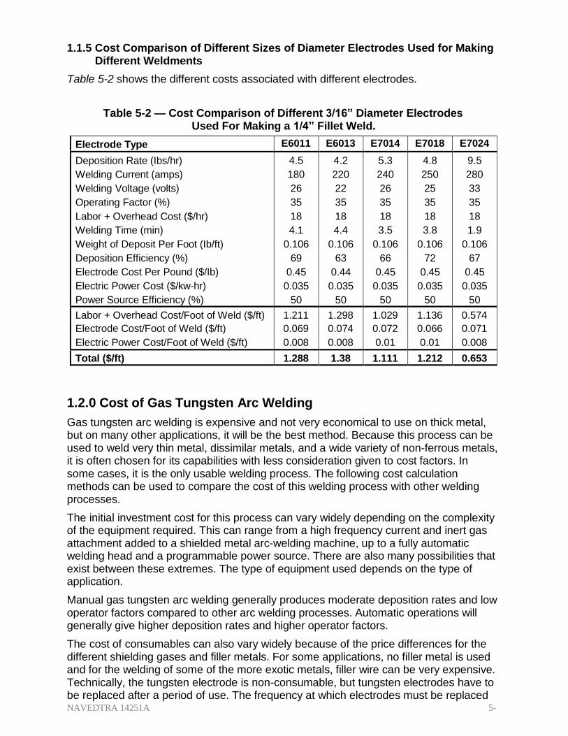
NAVEDTRA 14251A 5-10
1.1.5 Cost Comparison of Different Sizes of Diameter Electrodes Used for Making Different Weldments
Table 5-2 shows the different costs associated with different electrodes.
Table 5-2 — Cost Comparison of Different 3/16” Diameter Electrodes Used For Making a 1/4” Fillet Weld.
Electrode Type E6011 E6013 E7014 E7018 E7024
Deposition Rate (Ibs/hr)
Welding Current (amps)
Welding Voltage (volts)
Operating Factor (%)
Labor + Overhead Cost ($/hr)
Welding Time (min)
Weight of Deposit Per Foot (Ib/ft)
Deposition Efficiency (%)
Electrode Cost Per Pound ($/Ib)
Electric Power Cost ($/kw-hr)
Power Source Efficiency (%)
4.5
180
26
35
18
4.1
0.106
69
0.45
0.035
50
4.2
220
22
35
18
4.4
0.106
63
0.44
0.035
50
5.3
240
26
35
18
3.5
0.106
66
0.45
0.035
50
4.8
250
25
35
18
3.8
0.106
72
0.45
0.035
50
9.5
280
33
35
18
1.9
0.106
67
0.45
0.035
50
Labor + Overhead Cost/Foot of Weld ($/ft) 1.211 1.298 1.029 1.136 0.574
Electrode Cost/Foot of Weld ($/ft) 0.069 0.074 0.072 0.066 0.071
Electric Power Cost/Foot of Weld ($/ft) 0.008 0.008 0.01 0.01 0.008
Total ($/ft) 1.288 1.38 1.111 1.212 0.653
1.2.0 Cost of Gas Tungsten Arc Welding
Gas tungsten arc welding is expensive and not very economical to use on thick metal, but on many other applications, it will be the best method. Because this process can be used to weld very thin metal, dissimilar metals, and a wide variety of non-ferrous metals, it is often chosen for its capabilities with less consideration given to cost factors. In some cases, it is the only usable welding process. The following cost calculation methods can be used to compare the cost of this welding process with other welding processes.
The initial investment cost for this process can vary widely depending on the complexity of the equipment required. This can range from a high frequency current and inert gas attachment added to a shielded metal arc-welding machine, up to a fully automatic welding head and a programmable power source. There are also many possibilities that exist between these extremes. The type of equipment used depends on the type of application.
Manual gas tungsten arc welding generally produces moderate deposition rates and low operator factors compared to other arc welding processes. Automatic operations will generally give higher deposition rates and higher operator factors.
The cost of consumables can also vary widely because of the price differences for the different shielding gases and filler metals. For some applications, no filler metal is used and for the welding of some of the more exotic metals, filler wire can be very expensive. Technically, the tungsten electrode is non-consumable, but tungsten electrodes have to be replaced after a period of use. The frequency at which electrodes must be replaced

NAVEDTRA 14251A 5-10
depends on conditions such as the welder skill and the amount of welding current. A good approximation of the cost of the tungsten electrode is 4% of the shielding gas cost. The torch nozzles may also have to be replaced from time to time, depending on the type of nozzle and the care they are given by the welder.
The cost of this welding process is similar to SMAW but it has additional factors to consider in the shielding gas and the wear on the tungsten electrode. It consists of four major items including (1) the labor and overhead cost, (2) the filler metal cost, (3) the shielding gas cost, (4) the electric power cost, and one minor item, wear on the electrode.
1.2.1 Labor Cost
As discussed earlier, the labor and overhead costs are often combined in cost calculations; this is usually the largest cost factor in welding.
The operator factor in percentage is about the same for GTAW as for SMAW, but for different reasons. With GTAW, while little or no slag is produced, more time is needed for setup, preheating, and changing filler rods. However, because this process can be used manually and automatically, the operator factor can vary widely depending on which process you use.
For manual welding, the operator factor is relatively low and may range from about 10% to as high as 50%, but is normally in the range of 20% to 40%. Automatic welding generally gives high operator factors because it can usually proceed to completion without interruption. Operating factors for this can rise as high as 80% or more, depending on the specific application.
The deposition rates and travel speeds affect the labor and overhead costs because the rate at which the weld can be completed affects the productivity; travel speeds used with this process are often fairly low.
The equation for determining the labor and overhead cost per foot of weld is the same as SMAW:
Labor and Overhead Costs X
Pounds of Weld Deposit
Labor Cost
Hour Foot of Weld Foot of Weld
Deposition Rate X Operating Factor
The equation for determining your total labor cost is:
Labor and Overhead Costs
Total Labor Cost Total Welding TimeX
Hour
1.2.2 Filler Metal Cost
Filler metal costs are made up of the same three factors that affect SMAW: 1) weight of electrodes deposited per foot of weld dependent on the size of the weld to be made, 2) cost per pound of the electrode, and 3) deposition efficiency of the electrode. However,

NAVEDTRA 14251A 5-11
the deposition efficiency is nearly 100% for most GTAW welding operations because little or no filler metal is lost through spatter, vaporization, or stub end loss. For the calculations to be used for GTAW, a deposition efficiency of 100% will be assumed. Refer to Tables 5-3 and 5-4 for filler metal weights and consumption. The equations used for determining the cost of the filler metal are as follows:
For manual welding:
Filler Metal Cost Length of Deposition Wire Rate Per X X
Wire Cost
Wire Used Efficiency Unit of Length
X
Pound
Alternatively, for manual welding you can use:
Weight of Deposit X Filler Metal Costs Filler Metal Cost
Deposition Efficiency
For automatic welding:
Filler Metal Cost
Arc Wire Feed Wire Rate Per X X
Wire Cost
Time
Rate Unit of Length X
Pound
Table 5-3 — Inches Per Pound of Filler or Bare Electrode Wire.
Wire Diameter Metal or Alloy
Decimal Inches
Fraction Inches
Aluminum
Bronze, Alum. 10%
Bronze, Silicon
Copper (deox.)
Copper Nickel
Magnesium
Nickel
Steel, Mild
Steel
Stainless
0.02 32400 11600 10300 9800 9950 50500 9900 11100 10950
0.025 22300 7960 7100 6750 6820 34700 6820 7680 7550
0.03 14420 5150 4600 4360 4430 22400 4400 4960 4880
0.035 10600 3780 3380 3200 3260 16500 3240 3650 3590
0.04 8120 2900 2580 2450 2490 12600 2480 2790 2750
0.045 3/64 6410 2290 2040 1940 1970 9990 1960 2210 2170
0.062 1/16 3382 1120 1070 1020 1040 5270 1030 1160 1140
0.078 5/64 2120 756 675 640 650 3300 647 730 718
0.093 3/32 1510 538 510 455 462 2350 460 519 510
0.125 1/8 825 295 263 249 253 1280 252 284 279
0.156 5/32 530 189 169 160 163 825 162 182 179
0.187 3/16 377 134 120 114 116 587 115 130 127
0.25 1/4 206 74 66 62 64 320 63 71 70

NAVEDTRA 14251A 5-12
Table 5-4 — Filler Metal Consumption for Different Sizes and Types of Welds Made With Different Types of Base and Filler Metal.
Type of Weld Weight of Deposit (Lbs/ft)
T or S
(in)
T or S (mm)
Steel* Stainless
Steel
Nickel* Copper
Phosphor Bronze
Aluminum
Magnesium
1/16 1/8 3/16 1/4 3/8
1.6 3.2 4.8 6.4 9.6
.02 .05 .10 .16 .32
.03 .06 .11 .18 .37
.01 .02 .03 .05 .11
>.01 .01 .02 .04 .07
1/4 6.4 .19 .22 .07 .04
5/16 7.9 .27 .31 .09 .06
3/8 9.5 .37 .42 .13 .08
7/16 11.1 .48 .55 .16 .11
1/2 12.7 .61 .70 .21 .14
5/8 15.9 .91 1.04 .31 .20
3/4 19.1 1.28 1.47 .44 .29
1/8 3.2 .03 .03 .01 >.01
3/16 4.8 .06 .07 .02 .01
1/4 6.4 .11 .12 .04 .02
5/16 7.9 .17 .19 .06 .04
3/8 9.5 .24 .27 .08 .05
1/2 12.7 .43 .49 .15 .09
5/8 15.9 .66 .76 .23 .15
3/4 19.1 .96 1.09 .33 .21
1 25.4 1.70 1.94 .58 .38
5/8
15.9
.70
.80
.24
.16
3/4 19.1 .92 1.05 .32 .21
7/8 22.2 1.18 1.35 .40 .26
1 25.4 1.46 1.67 .50 .33
5/8
15.9
1.04
1.19
.36
.23
3/4 19.1 1.37 1.57 .47 .31
7/8 22.2 1.73 1.98 .59 .39
1 25.4 2.14 2.45 .73 .48
*Note: The metals within these two categories do not all have exactly the same density but are close enough to give a good approximation. These figures are based on an 1/16 inch (1.6 mm) reinforcement and a 100% deposition efficiency. For manual welding, approximately a 5% increase should be added to these figures.

NAVEDTRA 14251A 5-13
1.2.3 Shielding Gas Cost
The calculation for the cost of shielding gas is the same for GTAW, GMAW, and FCAW. The cost of the shielding gas depends on the gas flow rate, the arc time, and the cost for the type of shielding gas. Helium costs much more than argon per cubic foot and higher flow rates must be used with helium that can make it much more expensive than argon. The equation for determining the shielding gas cost is:
Shielded Gas Cost Arc Gas Flow Cost of Gas X X
Foot of Weld Time
Rate
Cubic Foot
1.2.4 Electric Power Cost
Electric power costs are the same in all the welding processes. The equation for the electric power cost is:
Electric Power Cost Welding Current X Welding Voltage Arc Power Cost X X
Foot of Weld Power Source Efficiency Time kw hr
To determine arc time per foot of weld, use:
ArcTime Length of Weld
For example:
Foot of Weld
Travel Speed
Arc Time
12 inch
X 1hour
.020 hr
Foot of Weld 10 in / min 60 min Foot of Weld
Then include your operator factor to calculate total welding time per foot of weld.
Total Welding Time Length of Weld
Foot of Weld Travel Speed X Operating Factor
For example:
Total Welding Time
12 inch
X 1hour
.057 hr
Foot of Weld 10 in / min X .35 60 min Foot of Weld
Or
Total Welding Time
ArcTime
Foot of Weld Operating Factor
For example:
Total Welding Time

NAVEDTRA 14251A 5-14
.020
hr
.057 Foot of Weld .35

NAVEDTRA 14251A 5-15
1.2.5 Examples
Now you are ready to calculate your total costs per foot of weld. Table 5-5 shows the figures used for the cost calculations of both manual and automatic gas tungsten arc welding. The following is a sample calculation of the manual method of welding (values taken from Table 5-5).
Total Labor Cost Labor and Overhead Costs
Foot of Weld Total Welding TimeX
Hour
Total Labor Cost
.057X $18.00
$1.026 Foot of Weld Hour
Filler Metal Cost Weight of Deposit X Filler Metal Costs
Foot of Weld
Deposition Efficiency
Filler Metal Cost .037X $1.60
Foot of Weld 1.00 $.059
Shielded Gas Cost Arc Gas Flow Cost of Gas X X
Foot of Weld Time
Rate
Cubic Foot
Shielded Gas Cost
.020 hr X 30 ft 3
/ hr X $.06
$.036
Foot of Weld ft 3
For this example of a calculation, assume a tungsten electrode cost at 4% of the cost of the shielding gas.
Electrode Cost .04X $.36$.001
Foot of Weld
Electric Power Cost Welding Current X Welding Voltage Arc Power Cost X X
Foot of Weld Power Source Efficiency Time kw hr
Electric Power Cost Amps X Volts kw
240
25 X .020 hr X $.035 X
1 $.008
Foot of Weld .50 kw hr 1000 w
Total Costs
GTAW example
Labor Filler Metal Shielding Gas Electrode Electric Power

NAVEDTRA 14251A 5-16
Foot of Weld
$1.026 $.059 $.036 $.001 $.008 $1.130

NAVEDTRA 14251A 5-17
1.2.6 Cost Comparison of Manual vs. Automatic
Table 5-5 — Cost comparison of Manual vs. Automatic welding
Method of Welding
Manual
Automatic
Welding Current (amps) 240 300 Welding Voltage (volts) 25 30
Travel Speed (in/min) 10 15
Gas Flow (f3/hr) 30 40
Welding Time (hr) 0.057 0.022
Arc Time (hr) 0.02 0.013
Labor + Overhead Cost ($/hr) 18 18
Operator Factor (%) 35 60
Weight of Deposit (Ibs) 0.037 0.037
Filler Wire Cost ($/Ib) 1.6 1.6
Deposition Efficiency (%) 100 100
Gas Cost ($/f3) 0.06 0.06
Gas Used (f3) 0.6 0.53
Electric Power Cost ($/kw-hr) 0.035 0.035
Power Source Efficiency (%) 50 50
Labor + Overhead Cost ($/ft) 1.026 0.396 Filler Wire Cost ($/ft) 0.059 0.059
Shielding Gas Cost ($/ft) 0.036 0.032
Electrode Cost ($/ft) 0.001 0.001
Electric Power Cost ($/ft) 0.008 0.008
Total Cost ($/ft) 1.130 0.496
1.3.0 Cost of Gas Metal Arc Welding
Gas metal arc welding can be used to weld many thicknesses and types of metals as economically as possible. It is usually selected because it is the least expensive process that can be used for many applications.
The initial investment for the equipment can vary depending on the complexity and size of the equipment used. The equipment for a semiautomatic welding station is much less expensive than the equipment required for a fully automatic set-up. The type of equipment depends on the type of application. Semiautomatic gas metal arc welding produces higher deposition rates and operator factors when compared to manual shielded metal arc welding.
The level of welder skill for gas metal arc welding is generally less than that required for shielded metal arc welding and gas tungsten arc welding. This helps to develop welds with a more consistent quality. Semiautomatic welding often competes against manual processes such as oxyacetylene welding, shielded metal arc welding, and gas tungsten arc welding for many applications. This process will generally produce higher deposition rates and operator factors than these other manual processes.
Automatic gas metal arc welding operations will give higher deposition rates and operator factors. The cost of electrode wires and shielding gases can vary widely because of price differences between different types and sizes of electrodes and

NAVEDTRA 14251A 5-18
different types of shielding gas. The cost of electric power consumed will depend on the type of machine, amount of welding, and the welding currents being used.
The cost of this welding process consists of four major items: labor and overhead, electrode, shielding gas, and electric power.
1.3.1 Labor Cost
GMAW can be used semiautomatically and automatically, which means the operator factor can vary widely. Operator factors for semiautomatic welding usually range from about 25% to as high as 60%. These operator factors are low compared to machine and automatic welding, where operator factors can range up to 80% or more depending on the application. The machine and automatic welding operations give higher operator factors because the welding can proceed to completion without interruption. The deposition rates and travel speeds affect the labor and overhead costs because the rate at which the electrode wire is deposited affects the productivity. The deposition rates and travel speeds used will be affected by the size of the electrode wire, the welding current, the thickness of the base metal, and the type of base metal.
The equation for determining the labor and overhead costs is:
Labor and Overhead Costs X
Pounds of Weld Deposit
Labor Cost
Hour Foot of Weld Foot of Weld
Deposition Rate X Operating Factor
Or
Labor and Overhead Costs Total Labor Cost Total Welding TimeX
Hour
1.3.2 Electrode Cost
As previously discussed, the cost of the electrode wire per weld is determined by several factors: the weight of the weld deposited, the cost per pound of the filler metal, and the deposition efficiency of the filler metal. Refer to Tables 5-3 and 5-4 which show the inches per pound and the filler metal consumption for different sizes and types of welds. The small diameter solid electrode wires used for this process cost more per pound than larger diameter solid electrode wires and covered electrodes. Electrode wire is less expensive per pound when supplied in a reel or large coil, as compared to a small coil. The total amount of wire purchased also affects the cost. Large shipments of wire will generally cost less per pound than small shipments.
The deposition efficiency is about 95% for most welding operations. Some of the electrode wire is lost to spatter and vaporization. This will vary slightly depending on the type of shielding gas. Argon will generally give higher deposition efficiencies than carbon dioxide due to the fact that less spatter is produced by spray transfer. The lowest deposition efficiencies are obtained when using the globular transfer mode because larger amounts of spatter are created.
The equations used for determining the cost of the electrode/filler metal are:

NAVEDTRA 14251A 5-19
Electrode Cost Arc Wire Feed Wire Rate Per X X
Wire Cost
Foot of Weld Time
Rate Unit of Length X
Pound
Electrode Cost
Or
Weight of Deposit X Filler Metal Costs
Foot of Weld
Deposition Efficiency
1.3.3 Shielding Gas Cost
Remember, the calculation for GTAW, GMAW, and FCAW is the same
The equation for determining the shielding gas cost is:
Shielded Gas Cost Arc Gas Flow Cost of Gas X X
Foot of Weld Time
Rate
Cubic Foot
1.3.4 Electric Power Cost
Remember, the calculation for SMAW, GTAW, GMAW, and FCAW is the same.
The equation for electric power cost is:
Electric Power Cost Welding Current X Welding Voltage Arc Power Cost X X
Foot of Weld Power Source Efficiency Time kw hr
1.3.5 Examples
Table 5-6 shows the figures used for cost calculations of semiautomatic and automatic gas metal arc welding and a comparison with shielded metal arc welding. In equations where arc time is necessary, it can be determined from the following equations:
ArcTime Length of Weld
Foot of Weld
Travel Speed
Arc Time
Or
Weight of Deposit
Foot of Weld
Deposition Rate
Arc Time
.106 lbs / ft
.017 hr
Foot of Weld 6.3lbs / hr

NAVEDTRA 14251A 5-20
The total welding time can then be determined by the equation:

NAVEDTRA 14251A 5-21
Total Welding Time ArcTime
Foot of Weld Operating Factor
Total Welding Time
.017 hr
.034 hr Foot of Weld
.50
The following is a sample calculation for making a ¼ in. (6.4mm) fillet weld with semiautomatic gas metal arc welding using the figures from Table 5-6.
Labor and Overhead Costs X
Pounds of Weld Deposit
Labor Cost
Hour Foot of Weld Foot of Weld
Deposition Rate X Operating Factor
$18.00 X
.106 lbs
Labor Cost
Hour Foot $.606
Foot of Weld 6.3lbs / hr X .50
Electrode Cost Weight of Deposit X Filler Metal Costs
Foot of Weld
Deposition Efficiency
Electrode Cost .106 lbs / ft X $.60 / lb
Foot of Weld .95 $.067
Electrode Cost
Or
Arc Wire Feed Wire Rate Per X X
Wire Cost
Foot of Weld Time
Rate Unit of Length X
Pound
Electrode Cost .017 hr
X 240 in
X 60 min
X 1lb
$.60
$.067
Foot of Weld
ft
min 1hr 2210 in X
Pound
Shielded Gas Cost Arc Gas Flow Cost of Gas X X

NAVEDTRA 14251A 5-22
hr
Foot of Weld Time
Rate
Cubic Foot
Shielded Gas Cost hr ft 3
.017 X
25 X
$.03 $.013
Foot of Weld ft
ft
3

NAVEDTRA 14251A 5-23
Electric Power Cost Welding Current X Welding Voltage Arc Power Cost X X
Foot of Weld Power Source Efficiency Time kw hr
Electric Power Cost Amps X Volts kw
200
73 X .017 hr X $.035 X
1 $.003
Foot of Weld .8 kw hr 1000 w
Total Costs
GMAW example
Labor Electrode Shielding Gas Electric Power
Foot of Weld
$.606 $.067 $.013 $.003 $.689
1.3.6 Cost Comparison of Manual (SMAW) vs. Semiautomatic (GMAW) and Automatic (GMAW)
Table 5-6 — Cost Comparison of Manual Shielded Metal Arc Welding vs.
Semiautomatic and Automatic Gas Metal Arc Welding for Making a 1/4 in. (6.4 mm) Fillet Weld.
Process Method of Welding
SMAW Manual
GMAW Semiautomatic
GMAW Automatic
Electrode Diameter (in) 3/16 0.045 1/16
Welding Current (amps) 250 200 350
Welding Voltage (volts) 25 23 24
Travel Speed (in/min) 9 15 25
Gas Flow (ft3/hr) 25 35
Welding Time (hr) 0.063 0.033 0.01
Arc Time (hr) 0.022 0.017 0.008
Wire Feed Speed (in/min) 240 270
Labor + Overhead Cost ($/hr) 18 18 18
Operator Factor (%) 35 50 80
Weight of Deposit (Ibs) 0.106 0.106 0.106
Electrode Cost ($/Ibs) 0.45 0.6 0.55
Deposition Efficiency (%) 72 95 95
Deposition Rate (Ibs/hr) 4.8 6.3 13.2
Gas Cost ($/ft3) 0.03 0.03
Gas Used (ft3) 0.33 0.29
Electric Power Cost ($/kw/hr) 0.035 0.035 0.035
Power Source Efficiency (%) 50 80 80
Labor + Overhead Cost ($/ft) 1.136 0.606 0.181
Electrode Cost ($/ft) 0.066 0.067 0.061
Shielding Gas Cost ($/ft) 0.013 0.008
Electric Power Cost ($/ft) 0.01 0.003 0.003
Total Cost ($/ft) 1.212 0.689 0.253
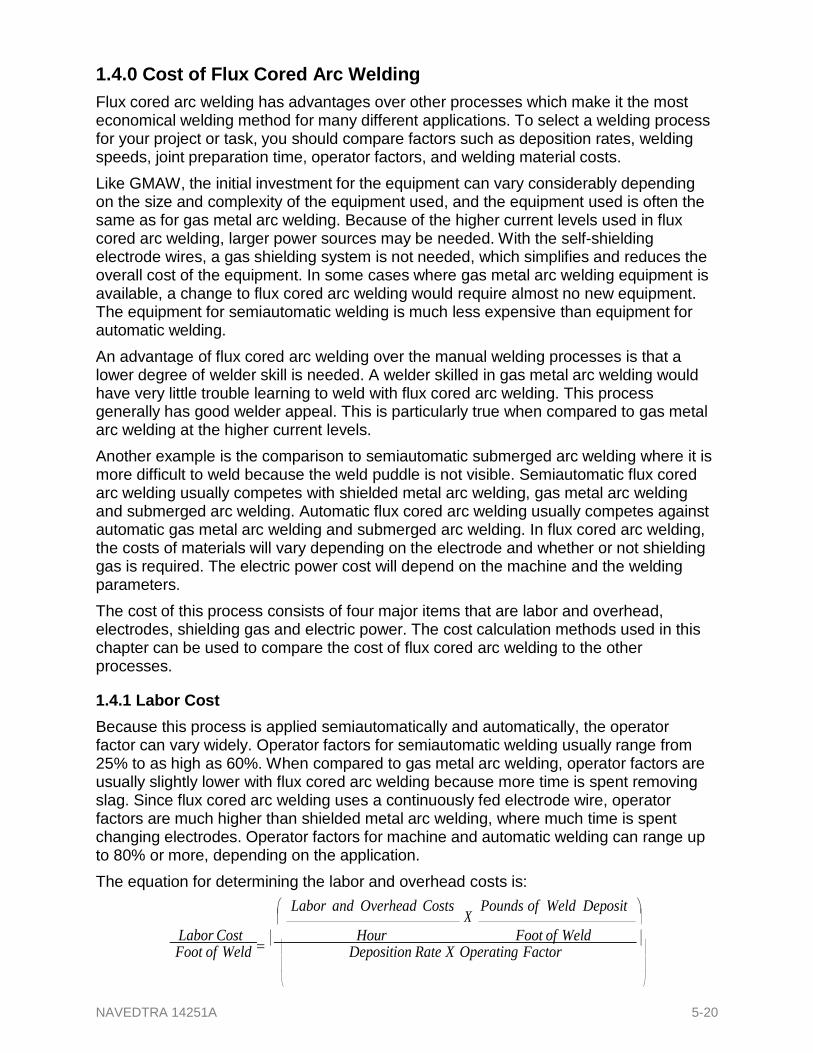
NAVEDTRA 14251A 5-20
1.4.0 Cost of Flux Cored Arc Welding
Flux cored arc welding has advantages over other processes which make it the most economical welding method for many different applications. To select a welding process for your project or task, you should compare factors such as deposition rates, welding speeds, joint preparation time, operator factors, and welding material costs.
Like GMAW, the initial investment for the equipment can vary considerably depending on the size and complexity of the equipment used, and the equipment used is often the same as for gas metal arc welding. Because of the higher current levels used in flux cored arc welding, larger power sources may be needed. With the self-shielding electrode wires, a gas shielding system is not needed, which simplifies and reduces the overall cost of the equipment. In some cases where gas metal arc welding equipment is available, a change to flux cored arc welding would require almost no new equipment. The equipment for semiautomatic welding is much less expensive than equipment for automatic welding.
An advantage of flux cored arc welding over the manual welding processes is that a lower degree of welder skill is needed. A welder skilled in gas metal arc welding would have very little trouble learning to weld with flux cored arc welding. This process generally has good welder appeal. This is particularly true when compared to gas metal arc welding at the higher current levels.
Another example is the comparison to semiautomatic submerged arc welding where it is more difficult to weld because the weld puddle is not visible. Semiautomatic flux cored arc welding usually competes with shielded metal arc welding, gas metal arc welding and submerged arc welding. Automatic flux cored arc welding usually competes against automatic gas metal arc welding and submerged arc welding. In flux cored arc welding, the costs of materials will vary depending on the electrode and whether or not shielding gas is required. The electric power cost will depend on the machine and the welding parameters.
The cost of this process consists of four major items that are labor and overhead, electrodes, shielding gas and electric power. The cost calculation methods used in this chapter can be used to compare the cost of flux cored arc welding to the other processes.
1.4.1 Labor Cost
Because this process is applied semiautomatically and automatically, the operator factor can vary widely. Operator factors for semiautomatic welding usually range from 25% to as high as 60%. When compared to gas metal arc welding, operator factors are usually slightly lower with flux cored arc welding because more time is spent removing slag. Since flux cored arc welding uses a continuously fed electrode wire, operator factors are much higher than shielded metal arc welding, where much time is spent changing electrodes. Operator factors for machine and automatic welding can range up to 80% or more, depending on the application.
The equation for determining the labor and overhead costs is:
Labor and Overhead Costs X
Pounds of Weld Deposit
Labor Cost
Hour Foot of Weld Foot of Weld
Deposition Rate X Operating Factor

NAVEDTRA 14251A 5-21
Or
Labor and Overhead Costs Total Labor Cost Total Welding TimeX
Hour
1.4.2 Electrode Cost
The deposition efficiency of flux cored wire is lower than that of solid wires because the flux core provides shielding gas and a slag covering. Self-shielding flux cored wires typically have a deposition efficiency of about 75-80%, which is much higher than obtained from covered electrodes. Gas shielded electrode wires have deposition efficiencies ranging from 80-90%. These are higher than self-shielding wires because less of the core becomes shielding gas and slag. With both types of flux cored wires, some wire is lost to spatter and vaporization. Spatter is generally higher with self- shielding electrodes that also contributes to the lower deposition efficiencies. The type of shielding gas used will have an effect on the deposition efficiency. Carbon dioxide will produce higher spatter levels than argon-carbon dioxide and argon-oxygen mixtures.
The equations used for determining the cost of an electrode wire are:
Electrode Cost Arc Wire Feed Wire Rate Per
X X
Wire Cost
Foot of Weld Time
Rate Unit of Length X
Pound
Electrode Cost
Or
Weight of Deposit X Filler Metal Costs
Foot of Weld
Deposition Efficiency
For the first equation, the wire weight per unit of length is needed. This figure will vary depending on the type of electrode wire used. Some flux-cored electrodes contain more core elements than others do. This is true of the self-shielding wires when compared to gas shielded wires. A good approximation of the percent fill or amount of flux in a tubular wire for cost calculations is about 16% by weight. This gives inches of wire per pound as shown in Table 5-7.
Table 5-7 — Inches of wire needed to make one pound.
Electrode Diameter in. Inches of wire per pound
.045 2375
1/16 1230
5/64 996
3/32 640
7/64 469
1/8 346

NAVEDTRA 14251A 5-22
3/32 225

NAVEDTRA 14251A 5-23
1.4.3 Shielding Gas Cost
If you do not use self-shielded flux cored wire you will have to determine shielding gas costs.
The equation for determining the shielding gas cost is:
Shielded Gas Cost Arc Gas Flow Cost of Gas X X
Foot of Weld Time
Rate
Cubic Foot
1.4.4 Electric Power Cost
The equation for electric power cost is:
Electric Power Cost Welding Current X Welding Voltage Arc Power Cost X X
Foot of Weld Power Source Efficiency Time kw hr
1.4.5 Examples
Table 5-8 shows the figures used for a cost calculation comparison of shielded metal arc welding, gas metal arc welding, flux cored arc welding using a self-shielding wire, flux cored arc welding using a gas-shielded wire, and submerged arc welding. The examples given are typical but the exact data should be obtained from the manufacturer’s data sheets and the actual welding conditions. In equations where arc time is necessary, it can be determined from the following equation.
ArcTime Length of Weld X Number of Passes
Foot of Weld
Travel Speed
Arc Time
Or
Weight of Deposit
Foot of Weld
Deposition Rate
The total welding time can then be determined by the equation:
Total Welding Time ArcTime
Foot of Weld Operating Factor
The following sample calculation is for making a ½ inch (12.7 mm) fillet weld in the horizontal position using semiautomatic flux cored arc welding with a gas-shielded electrode.
Labor and Overhead Costs X
Pounds of Weld Deposit
Labor Cost
Hour Foot of Weld Foot of Weld

NAVEDTRA 14251A 5-24
Deposition Rate X Operating Factor

NAVEDTRA 14251A 5-25
hr
$18.00 X
.425lbs
Labor Cost
Hour Foot $1.001
Foot of Weld 17 lbs / hr X .45
Electrode Cost Weight of Deposit X Filler Metal Costs
Foot of Weld
Deposition Efficiency
Electrode Cost .425lbs / ft X $.75 / lb
Foot of Weld .90 $.345
Shielded Gas Cost Arc Gas Flow Cost of Gas X X
Foot of Weld Time
Rate
Cubic Foot
Arc Time Weight of Deposit
Foot of Weld
Deposition Rate
Arc Time
.425 lbs / ft
.0250 hr
Foot of Weld 17.0 lbs / hr
Shielded Gas Cost hr ft 3
.0250 X
35 X
$.025 $.022
Foot of Weld ft
ft
3
Electric Power Cost Welding Current X Welding Voltage Arc Power Cost X X
Foot of Weld Power Source Efficiency Time kw hr
Electric Power Cost Amps X Volts kw
475
29 X .0250X $.04 X
1 $.017
Foot of Weld .8 kw hr 1000 w
Total Costs
Labor
FCAW example
Electrode Shielding Gas Electric Power
$1.384 Foot of Weld $1.001 $.345 $.022 $.017

NAVEDTRA 14251A 5-26
1.4.6 Cost Comparison of Between (SMAW), (GMAW) and (FCAW)
Table 5-8 — Cost Comparisons Between SMAW, GMAW, FCAW, and Submerged Arc Welding of 1/2 in. (12.7 mm) Fillet Weld in the Horizontal Position.
Process SMAW GMAW FCAW FCAW SAW Method of Application Manual Semiautomatic Semiautomatic Semiautomatic Semiautomatic
Electrode Type E7024 E70S-3 E70T-4 E70T-1 EM 12K
Electrode Diameter (in.) 1/4 1/16 3/32 3/32 3/32
Welding Current (amps) 380 350 375 475 550
Welding Voltage (volts) 33 25 28 29 33
Travel Speed (in./min.) 11-3 18-3 -- 15 12
Gas Flow (f3/hr.) -- 45 -- 35 --
Total Welding Time (hr.) 0.0995 0.8654 0.0587 0.0556 0.0605
Arc Time (hr.) 0.0348 0.0327 0.0264 0.025 0.0272
Wire Feed Speed (in./min.) -- 270 215 200 120
Labor and Overhead Cost ($/hr.) 18 18 18 18 18
Operator Factor (%) 35 50 45 45 45
Weight of Deposit (Ibs.) 0.425 0.425 0.425 0.425 0.425
Electrode Cost ($/Ib.) 0.5 0.6 0.6 0.75 0.52
Deposition Efficiency (%) 67 93 80 90 100*
Deposition Rate (Ibs./hr.) 12.2 13 16.1 17 15.6
Gas Cost ($/f3) -- 0.025 -- 0.025 --
Gas Used (f3) -- -- -- -- --
Flux Cost ($/Ib.) -- -- -- -- 0.5
Flux Used (Ibs.) -- -- -- -- 0.53 Electric Power Cost ($/kw- hr.) 0.04 0.04 0.04 0.04 0.04
Power Source Efficiency (%) 50 80 80 80 80
Labor and Overhead Cost ($/ft.) 1.71 1.177 1.057 1.001 1.09 Electrode Cost ($/ft.) 0.317 0.274 0.318 0.354 0.221
Shielding Gas Cost ($/ft.) -- 0.037 -- 0.022 --
Flux Cost (#/ft.) -- -- -- -- 0.266
Electric Power Cost ($/ft.) 0.035 0.014 0.014 0.017 0.024
Total Cost ($/ft.) 2.143 1.502 1.389 1.384 1.601
6XPPDU\
This chapter discussed how to determine the welding costs of multiple processes.

NAVEDTRA 14251A 5-27
Review Questions 6HOHFW WKH &RUUHFW 5HVSRQVH 1. Which of the following is NOT a fixed welding cost?
A. Joint preparation B. Filler metal C. Inspection D. Preheating
2. What costs are used to determine the overall cost of SMAW?
A. Labor and overhead, electrode, and electric power B. Labor, machinery, filler metal, and shielding gas C. Electrical power, filler metal, shielding gas D. Electrode, Labor and overhead, shielding gas
3. The percentage of time that a welder is actually welding is called?
A. Labor cost B. Welding cost C. Operator factor D. Deposition efficiency
4. When calculating deposition efficiency for SMAW, what is the assumed stub loss
in inches?
A. 1
B. 2
C. 3
D. 4
5. Of all of the cost factors, which is the least significant?
A. Electrode B. Power C. Labor D. Shielding gas
6. Why is GTAW considered a viable welding process?
A. Inexpensive B. Easy to use C. Capabilities on very thin metal D. Shielding gas costs

NAVEDTRA 14251A 5-28
7. What is the assumed disposition efficiency when calculating GTAW filler metal costs?
A. 50%
B. 70%
C. 85%
D. 100%
8. How is arc time determined?
A. Travel speed divided by length of weld B. Arc ignition divided by arc termination C. Length of weld divided by travel speed D. Thickness of weld multiplied by weld current
9. What is the greatest cost factor difference between manual and automatic GTAW
processes?
A. Filler wire B. Shielding gas C. Electrode D. Labor and overhead
10. What is the least expensive welding process that can be used for many
applications?
A. GMAW B. GTAW C. SMAW D. SAW
11. What factors directly affect the deposition rates of electrode wire?
A. Type of base metal B. Type of filler metal C. Weld position D. Shielding gas
12. Which mode of transfer provides the lowest deposition efficiency when using the
GMAW process?
A. Short circuiting B. Globular C. Spray D. Pulsed
13. What is an advantage of FCAW over other welding processes?
A. Lower initial costs B. Lower level of welder skill needed C. Welds the thickest metal D. Can be used for unique metals such as titanium

NAVEDTRA 14251A 5-29
14. (True or False) Spatter is generally less with self-shielding electrodes.
A. True B. False

NAVEDTRA 14251A 5-30
Trade Terms Introduced in this Chapter
None

NAVEDTRA 14251A 5-31
Additional Resources and References
This chapter is intended to present thorough resources for task training. The following reference works are suggested for further study. This is optional material for continued education rather than for task training.
Flux-Cored Arc Welding Basic. EW-492 Technical Guide. Hobart Institute of Welding Technology, Troy Ohio,1998
Gas Metal Arc Welding Basic. EW-473 Technical Guide. Hobart Institute of Welding Technology, Troy Ohio,1998
Gas Tungsten Arc Welding Basic. EW-470 Technical Guide. Hobart Institute of Welding Technology, Troy Ohio,1998
Shielded Metal Arc Welding Basic. EW-472 Technical Guide. Hobart Institute of Welding Technology, Troy Ohio,1998

NAVEDTRA 14251A 5-30
CSFE Nonresident Training Course – User Update
CSFE makes every effort to keep their manuals up-to-date and free of technical errors. We appreciate your help in this process. If you have an idea for improving this manual, or if you find an error, a typographical mistake, or an inaccuracy in CSFE manuals, please write or email us, using this form or a photocopy. Be sure to include the exact chapter number, topic, detailed description, and correction, if applicable. Your input will be brought to the attention of the Technical Review Committee. Thank you for your assistance.
Write: CSFE N7A 3502 Goodspeed St. Port Hueneme, CA 93130
FAX: 805/982-5508
E- mail: [email protected]
Rate_ Course Name
Revision Date Chapter Number Page Number(s)
Description
(Optional) Correction
(Optional) Your Name and Address

NAVEDTRA 14251A AI-1
APPENDIX I MATHEMATICS
The purpose of this mathematics appendix is twofold; first, it is a refresher for the Seabees who have encountered a time lapse between his or her schooling in mathematics; second, and more important, this section applies mathematics to the tasks that can not be accomplished without the correct use of mathematical equations.
Linear Measurement
Measurements are most often made in feet (ft) and inches (in). It is necessary that a Seabee know how to make computations involving feet and inches.
Changing Inches to Feet and Inches
To change inches to feet and inches, divide inches by 12. The quotient will be the number of feet, and the remainder will be inches.
Changing Feet and Inches to Inches
To change feet and inches to inches, multiply the number of feet by 12 and add the number of inches. The results will be inches.
Changing Inches to Feet in Decimal Form
To change inches to feet in decimal form, divide the number of inches by 12 and carry the result to the required number of places.
Changing Feet to Inches in Decimal Form
To change feet in decimal form to inches, multiply the number of feet in decimal form by 12.
Addition of Feet and Inches
A Seabee often finds it necessary to combine or subtract certain dimensions which are given in feet and inches.
Arrange in columns of feet and inches and add separately. If the answer in the inches column is more than 12, change to feet and inches and combine feet.
Subtraction of Feet and Inches
Arrange in columns with the number to be subtracted below the other number. If the inches in the lower number are greater, borrow 1 foot (12 Inches) from the feet column in the upper number. Subtract as in any other problem.
Multiplication of Feet and Inches
Arrange in columns. Multiply each column by the required number. If the inches column is greater than 12, change to feet and inches then add to the number of feet.

NAVEDTRA 14251A AI-2
Division of Feet and Inches
In dividing feet and inches by a given number, the problem should be reduced to inches unless the number of feet will divide by the number evenly.
To divide feet and inches by feet and inches, change to inches or feet (decimals).
Angles
When two lines are drawn in different directions from the same point, an angle is formed.
Angles are of four types:
● Right angle is a 90° angle.
● Acute angles are angles less than 90°.
● Obtuse angles are angles greater than 90°, but less than 180°.
● Reflex angle is an angle greater than 180°.
Measurement of Angles
Observe that two straight lines have been drawn to form four right angles. Refer to Figure A-1.
In order to have a way to measure angles, a system of angle-degrees has been established. Assume that each of the four right angles is divided into 90 equal angles. The measure of each is 1 angle degree; therefore, in the four right angles, there are 4 x 90°, or 360 angle degrees. For accurate measurement, degrees have been subdivided into minutes and minutes into seconds.
1 degree= 60 minutes (’).
1 minute= 60 seconds (“).
Figure A-1 — Right angles.

NAVEDTRA 14251A AI-3
Relationship of Angles
Figure A-2 — Relationship of angles.
1. ZOY and ZOX are supplementary angles and their total measure in degrees is equal to 180°. When one straight line meets another, two supplementary angles are formed. One is the supplement of the other. Refer to Figure A-2, View 1.
2. DAC and CAB are complementary angles and their total is a right angle or 90°. Refer to Figure A-2, View 2.
Two angles whose sum is 90° are said to be complementary, and one is the complement of the other.
3. MOP and RON are a pair of vertical angles and are equal. Refer to Figure A- 2, View 3.
When two straight lines cross, two pairs of vertical angles are formed. Pairs of vertical angles are equal.
Bisecting Angles
To bisect an angle merely means to divide the angle into two equal angles. This may be done by use of a compass.
Perpendicular Lines
Lines are said to be perpendicular when they form a right angle (90°).
Parallel Lines
Two lines are said to be parallel if they are equidistant (equally distant) at all points.
Facts about parallel lines:
Two straight lines lying in the same plane either intersect or are parallel.
Through a point there can be only one parallel drawn to a given line.
If two lines are perpendicular to the third, and in the same plane, they are parallel.

NAVEDTRA 14251A AI-4
Plane Shapes
A plane shape is a portion of a plane bounded by straight or curved lines or a combination of the two.
The number of different types of plane shapes is infinite, but we are concerned with those which are of importance to you as a Seabee. We will cover the circle, triangle, quadrilateral, other polygons, and ellipses.
Definitions:
Circles
A CIRCLE is a closed curved line in which any point on the curved line is equidistant from a point called the center. (Circle O). Refer to Figure A-3.
A RADIUS is a line drawn from the center of a circle to a point on a circle. (As OA, OB, OX, and OY). Refer to Figure A-3.
A DIAMETER is a line drawn through the center of a circle with its ends lying on the circle. Refer to Figure A-3.
A DIAMETER is twice the length of a radius. (AB is a diameter of circle O) Refer to Figure A-3.
A CHORD is a line joining any two points lying on a circle. (CD is a chord of circle O.) Refer to Figure A-3.
Figure A-3 — Circle.
An ARC is a portion of the closed curved lines which forms the circle. It is designated by CD. An arc is said to be subtended by a chord. Chord CD subtends arc CD. Refer to Figure A-3.
A TANGENT is a straight line which touches the circle at one and only one point. (Line MZ is a tangent to circle O.) Refer to Figure A-3.
A CENTRAL ANGLE is an angle whose vertex is the center of a circle and whose side are radii of the circle. (As XOY, YOA, and XOB.) Refer to Figure A-3.
CONCENTRIC CIRCLES are circles having the same center and having different radii.
The CIRCUMFERENCE of a circle is the distance around the circle. It is the distance on the curve from C to A to X to Y to B to D and back to C. Refer to Figure A-3.

NAVEDTRA 14251A AI-5
Triangles
A triangle is a plane shape having 3 sides. Its name is derived from its three (tri) angles.
1. Equilateral - all sides are equal, all angles are equal, and all angles are 60°. Refer to Figure A-4.
2. Isosceles - two sides are equal and two angles are equal. Refer to Figure A-4.
3. Scalene - all sides are unequal and all angles are unequal. Refer to Figure A-4.
4. Right - one right angle is present. Refer to Figure A-4.
Figure A-4 — Types of triangles.
Altitudes and Medians
The altitude and median of a triangle are not the same; the difference is pointed out in the following definitions:
1. The altitude of a triangle is a line drawn from the vertex, perpendicular to the base. Refer to Figure A-5, View 1.
2. The median of a triangle is a line drawn from the vertex to the midpoint of the base. Refer to Figure A-5, View 2.
Figure A-5 — Altitude and median of a triangle.

NAVEDTRA 14251A AI-6
Construction of Triangles
There are many ways to construct a triangle, depending upon what measurements are known to you. The following definitions will assist you.
1. A triangle may be constructed if the lengths of three sides are known.
2. A triangle may be constructed if two sides and the included angle (angle between the sides) are known.
3. A triangle may be constructed if two angles and the included side are given.
4. A right triangle may be constructed if the two sides adjacent to the right angle are known.
5. A right triangle may be constructed by making the sides 3, 4, and 5 inches or multiples or fractions thereof.
Quadrilaterals
A quadrilateral is a four-sided plane shape. There are many types, but only the trapezoid, parallelogram, rectangle, and square are described here.
Trapezoid is a quadrilateral having only two sides parallel. If the other two sides are equal, it is an isosceles trapezoid. BF is the altitude of the trapezoid. See Figure A-6.
Parallelogram is a quadrilateral having opposite sides parallel. Refer to Figure A-7.
1. AB is parallel to CD.
2. AC is parallel to BD.
3. AD and CB are diagonals.
4. Diagonals bisect each other so CO = OB and AO = OD.
5. Opposite angles are equal. ACD = DBA and CAB = BDC.
6. If two sides of a quadrilateral are equal and parallel, the figure is a parallelogram.
7. A parallelogram may be constructed if two adjoining sides and one angle are known.
Rectangle is a parallelogram having one right angle. Refer to Figure A-8.
1. ABCD is a parallelogram having one right angle. This, of course, makes all angles right angles.
2. AC and BD are diagonals.
3. O is the midpoint of AC and BD and OB = OC = OD = OA.
4. O is equidistant from BC and AD and is also equidistant from AB and CD.
5. A rectangle may be constructed if two adjoining sides are known.
Square is a rectangle having its adjoining sides equal. Refer to Figure A-9.
Figure A-6 — Trapezoid.
Figure A-7 — Parallelogram.
Figure A-8 — Rectangle.

NAVEDTRA 14251A AI-7
1. ABCD is a square.
2. AC and BD are diagonals.
3. O is the geometric center of the square. AO = OC = OB = OD.
4. O is equidistant from all sides.
5. A square may be constructed if one side is known.
Polygons
A polygon is a many-sided plane shape. It is said to be regular if all sides are equal and irregular when they are not. Only regular polygons are described here.
Figure A-9 —
Square.
Triangles and quadrilaterals fit the description of a polygon and have been covered previously. Three other types of regular polygons are shown in Figure A-10. Each one is inscribed in a circle. This means that all vertices of the polygon lie on the circumference of the circle.
Note that the sides of each of the inscribed polygons are actually equal chords of the circumscribed circle. Since equal chords subtend equal arcs, by dividing the circumference into an equal number of arcs, a regular polygon may be inscribed in a circle. Also note that the central angles are equal because they intercept equal arcs. This gives a basic rule for the construction of regular polygons inscribed in a circle as follows:
To inscribe a regular polygon in a circle, create equal chords of the circle by dividing the circumference into equal arcs or by dividing the circle into equal central angles.
Dividing a circle into a given number of parts has been discussed, so construction should be no problem. Since there are 360 degrees around the center of the circle, you should have no problem in determining the number of degrees to make each equal central angle.
Figure A-10 — Types of polygons.

NAVEDTRA 14251A AI-8
Methods for Constructing Polygons
The three methods for constructing polygons described here are the pentagon, hexagon, and octagon.
The Pentagon is a developed by dividing the circumference into 5 equal parts.
The Hexagon is developed by dividing the circumference into 6 equal parts.
The Octagon method has been developed by creating central angles of 90° to divide a circle into 4 parts and bisecting each arc to divide the circumference into 8 equal parts.
Ellipses
An ellipse is a plane shape generated by point P, moving in such
a manner that the sum of its distances from two points, F 1 and
F 2 , is constant. Refer to Figure A-11.
BF 1 + PF 2 = C = (a constant)
AE is the major axis.
BD is the minor axis.
Figure A-11 — Ellipses.
Perimeters and Circumferences
Perimeter and circumference have the same meaning; that is, the distance around. Generally, circumference is applied to a circular object and perimeter to an object bounded by straight lines.
Perimeter of a Polygon
The perimeter of a triangle, quadrilateral, or any other polygon is actually the sum of the sides.
Circumference of a Circle
Definition of Pi: Mathematics have established that the relationship of the circumference
to the diameter of a circle is a constant called Pi and written as . The numerical value of this constant is approximately 3.141592653. For our purposes 3.1416 or simply 3.14 will suffice.
The formula for the circumference of a circle is C = 2 D where C is the circumference and D is the diameter since D = 2R where R is the radius, the formula may be written as C = 2 R.
All areas are measured in squares.
Areas
The area of a square is the product of two of its sides and since both sides are equal, it may be said to be square of its side.
NOTE
The area of any plane surface is the measure of the number of squares contained in the object. The unit of measurement is the square of the unit which measures the sides of the square.

NAVEDTRA 14251A AI-9
Where:
A = area of a rectangle
L = length of a rectangle
W = width of a rectangle
Area of Rectangle
A = L x W Area of a Cross Section
The cross section of an object is a plane figure established by a plane cutting the object at right angles to its axis. The area of this cross section will be the area of the plane figure produced by this cut.
The area of the cross section is L x W.
The most common units are square inches, square feet, square yards and in roofing, “squares.”
1 square foot = 144 square inches
1 square yard = 9 square feet
1 square of roofing = 100 square feet
Common Conversions
1. To convert square inches to square feet, divide square inches by 144.
2. To convert square feet to square inches, multiply by 144.
3. To convert square feet to square yards, divide by 9.
4. To convert square yards to square feet, multiply by 9.
5. To convert square feet to squares, divide by 100.
Conversion of Units of Cubic Measure
It is often necessary to convert from one cubic measure to another. The conversion factors used are as follows:
1. 1 cubic foot = 1,728 cubic inches
2. 1 cubic yard = 27 cubic feet
3. 1 cubic foot = 7.48 US gallons (liquid measure)
4. 1 us gallon (liquid measure) = 231 cubic inches
5. 1 bushel (dry measure) = 2,150.42 cubic inches
Area of a Circle
The formula for the area of a circle is:
Where:
A = area of circle
r = radius of circle
= 3.1416
A = r 2

NAVEDTRA 14251A AI-10
2
Since r = d/2 where d is the diameter of a circle, the formula for the area of a circle in terms of its diameter is:
A = ( d 2
d 2
) 4
Geometric Solids
In describing plane shapes, you use only two dimensions: width and length; there is no thickness. By adding the third dimension, you describe a solid object.
Consider the solids described below.
Prism - is a figure whose two bases are polygons, alike in size and shape, lying in parallel planes and whose lateral edges connect corresponding vertices and are parallel and equal in length. A prism is a right prism if the lateral edge is perpendicular the base. The altitude of a prism is the perpendicular distance between the bases.
Cone - is a figure generated by a line moving in such a manner that one end stays fixed at a point called the “vertex.” The line constantly touches a plane curve which is the base of the cone. A cone is a circular cone if its base is a circle. A circular cone is a right circular cone if the line generating it is constant in length. The altitude of a cone is the length of a perpendicular to the plane of the base drawn from the vertex.
Pyramid - is a figure whose base is a plane shape bounded by straight lines and whose sides are triangular plane shapes connecting the vertex and a line of the base. A regular pyramid is one whose base is a regular polygon and whose vertex lays on a perpendicular to the base at its center. The altitude of a pyramid is the length of a perpendicular to the plane of the base drawn from the vertex.
Circular Cylinder - is a figure whose bases are circles lying in parallel planes connected by a curved lateral surface. A right circular cylinder is one whose lateral surface is perpendicular to the base. The altitude of a circular cylinder is the perpendicular distance between the planes of the two bases.
Measurement of Volume
Volume is measured in terms of cubes.
Common Volume Formulas
All factors in the formulas must be in the same linear units. As an example, one term could not be expressed in feet while other terms are in inches.
Volume of a Rectangular Prism
V = L x W x H
Where:
V = Volume in cubic inches
W = Width of the base in linear units
L = Length of base in linear units
H = Altitude of the prism in linear units

NAVEDTRA 14251A AI-11
Volume of a Cone
V = A x h
3
Where:
V= Volume of a cone in cubic units
A = Area of the base in square units
h = Altitude of a cone in linear units
r = Radius of the base
d = Diameter of the base
Or
r 2 h
V = 3
Or
d 2
h V =
12
Volume of a Pyramid
Where:
V = Volume in cubic units
A = Area of base in square units
h = Altitude in linear units
V = A h 3
Volume of a Cylinder
V = Ah
Or
V = r 2 h
Or
d 2 h
V = 4
Where:
V = Volume in cubic units
A = Area of the base in square units
h = Altitude in linear units
r = Radius of the base
d = Diameter of the base
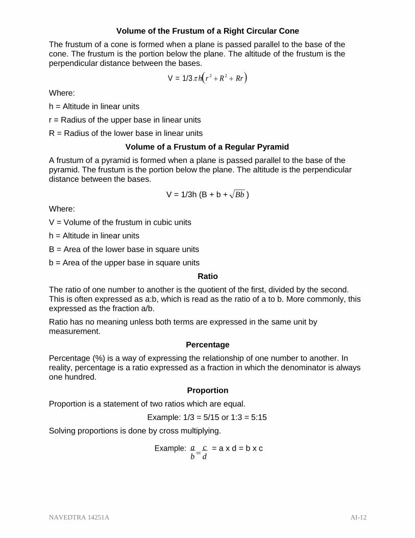
NAVEDTRA 14251A AI-12
Volume of the Frustum of a Right Circular Cone
The frustum of a cone is formed when a plane is passed parallel to the base of the cone. The frustum is the portion below the plane. The altitude of the frustum is the perpendicular distance between the bases.
V = 1/3 hr 2 R
2 Rr
Where:
h = Altitude in linear units
r = Radius of the upper base in linear units
R = Radius of the lower base in linear units
Volume of a Frustum of a Regular Pyramid
A frustum of a pyramid is formed when a plane is passed parallel to the base of the pyramid. The frustum is the portion below the plane. The altitude is the perpendicular distance between the bases.
Where:
V = 1/3h (B + b + Bb )
V = Volume of the frustum in cubic units
h = Altitude in linear units
B = Area of the lower base in square units
b = Area of the upper base in square units
Ratio
The ratio of one number to another is the quotient of the first, divided by the second. This is often expressed as a:b, which is read as the ratio of a to b. More commonly, this expressed as the fraction a/b.
Ratio has no meaning unless both terms are expressed in the same unit by measurement.
Percentage
Percentage (%) is a way of expressing the relationship of one number to another. In reality, percentage is a ratio expressed as a fraction in which the denominator is always one hundred.
Proportion
Proportion is a statement of two ratios which are equal.
Example: 1/3 = 5/15 or 1:3 = 5:15
Solving proportions is done by cross multiplying.
Example: a
c = a x d = b x c b d

NAVEDTRA 14251A AI-13
Law of Pythagoras
The Law of Pythagoras is the square of the hypotenuse of a right triangle equals the
sum of the two legs. It is expressed by the formula a 2 b
2 c
2 .
Right Triangle: a triangle having one right angle
Hypotenuse: The hypotenuse of a right triangle is the side opposite the right angle
Leg: The leg of a right triangle is a side opposite and acute angle of a right triangle.
METRIC CONVERSION TABLES
Length Conversion
When You Know: You Can Find: If You Multiply By:
inches millimeters 25.4
inches centimeters 2.54
feet centimeters 30
feet meters 0.3
yards centimeters 90
yards meters 0.9
miles kilometers 1.6
miles meters 1609
millimeters inches 0.04
centimeters inches 0.4
centimeters feet 0.0328
meters feet 3.3
centimeters yards 0.0109
meters yards 1.1
meters miles 0.000621
kilometers miles 0.6
meters nautical miles 0.00054
nautical miles meters 1852

NAVEDTRA 14251A AI-14
Weight Conversion
When You Know: You Can Find: If You Multiply By:
ounces grams 28.3
pounds kilograms 0.45
short tons megagrams 0.9
(2000 lbs) (metric tons)
grams ounces 0.0353
kilograms pounds 2.2
megagrams short tons 1.1
(metric tons) (2000 lbs)
Temperature Conversion
When You Know: You Can Find: If You Multiply By:
Degrees Fahrenheit
Degrees Celsius
Degrees Celsius
Degree Celsius
Degree Fahrenheit
Kelvins
Subtract 32 then multiply by 5/9
Multiply by 9/5 then add 32
Add 273.15

NAVEDTRA 14251A AI-15
Volume Conversion
When You Know: You Can Find: If You Multiply By:
teaspoons milliters 5
tablespoons milliters 1 5
fluid ounces milliters 3 0
cups liters 0.24
pints liters 0.47
quarts liters 0.95
gallons liters 3.8
milliters teaspoons 0.2
milliters tablespoons 0.067
milliters fluid ounces 0.034
liters cups 4.2
liters pints 2.1
liters quarts 1.06
liters gallons 0.26
cubic feet cubic meters 0.028
cubic yards cubic meters 0.765
cubic meters cubic feet 35.3
cubic meters cubic yards 1.31

NAVEDTRA 14251A AI-16
Area Conversions
When You Know: You Can Find: If You Multiply By:
Square inches Square centimeters 6.45
Square inches Square meters 0.000 6
Square feet Square centimeters 929
Square feet Square meters 0.0929
Square yards Square centimeters 8.360
Square yards Square meters 0.836
Square miles Square kilometers 2.6
Square centimeters Square inches 0.155
Square meters Square inches 1550
Square centimeters Square feet 0.001
Square meters Square feet 10.8
Square centimeters Square yards 0.00012
Square meters Square yards 1.2
Square kilometers Square miles 0.4

NAVEDTRA 14251A AI-17
Table A-1 — Decimal Equivalents.
Fraction 16th 32nd 64th Decimal Fraction 16th 32nd 64th Decimal
1 .015625 33 .515625
1 2 .03125 17 34 .53125
3 .046875 35 .54875
1 2 4 .0625 9 18 36 .5625
5 .078125 37 .578125
3 6 .09375 19 38 .59375
7 .109375 39 .609375
1/8 2 4 8 .125 5/8 10 20 40 .625
9 .140625 41 .640625
5 10 .15625 21 42 .65625
11 .171875 43 .671875
3 6 12 .1875 11 22 44 .6875
13 .203125 45 .703125
7 14 .21875 23 46 .71875
15 .234375 47 .734375
1/4 4 8 16 .25 3/4 12 24 48 .75
17 .265625 49 .765625
9 18 .28125 25 50 .78125
19 .296875 51 .796875
5 10 20 .3125 13 26 52 .8125
21 .328125 53 .818225
11 22 .34375 27 54 .84375
23 .359375 55 .859375
3/8 6 12 24 .375 7/8 14 28 56 .875
25 .390623 57 .890625
13 26 .40625 29 58 .90625
27 .421875 59 .921875
7 14 28 .4375 15 30 60 .9375
29 .453125 61 .953125
15 30 .46875 31 62 .96875
31 .484375 63 .984375
1/2 8 16 32 .5 1 16 32 64 1.0

NAVEDTRA 14251A AI-18
Table A-2 — Metric measures of length.
10 millimeters = 1 centimeter (cm)
10 centimeters = 1 decimeter (dm)
10 decimeters = 1 meter (m)
10 meters = 1 decameter (dkm)
10 decameters = 1 hectometer (hm)
10 hectometers = 1 kilometer (km)
Table A-3 — Conversion of inches to millimeters. Inches Millimeters Inches Millimeters Inches Millimeters Inches Millimeters
1 25.4 26 660.4 51 1295.4 76 1930.4
2 50.8 27 685.8 52 1320.8 77 1955.8
3 76.2 28 711.2 53 1346.2 78 1981.2
4 101.6 29 736.6 54 1371.6 79 2006.6
5 127 30 762 55 1397 80 2032
6 152.4 31 787.4 56 1422.4 81 2057.4
7 177.8 32 812.8 57 1447.8 82 2082.8
8 203.2 33 838.2 58 1473.2 83 2108.2
9 228.6 34 863.6 59 1498.6 84 2133.6
10 254 35 889 60 1524 85 2159
11 279.4 36 914.4 61 1549.4 86 2184.4
12 304.8 37 939.8 62 1574.8 87 2209.8
13 330.2 38 965.2 63 1600.2 88 2235.2
14 355.6 39 990.6 64 1625.6 89 2260.6
15 381 40 1016 65 1651 90 2286
16 406.4 41 1041.4 66 1676.4 91 2311.4
17 431.8 42 1066.8 67 1701.8 92 2336.8
18 457.2 43 1092.2 68 1727.2 93 2362.2
19 482.6 44 1117.6 69 1752.6 94 2387.6
20 508 45 1143 70 1778 95 2413
21 533.4 46 1168.4 71 1803.4 96 2438.4
22 558.8 47 1193.8 72 1828.8 97 2463.8
23 584.2 48 1219.2 73 1854.2 98 2489.2
24 609.6 49 1244.6 74 1879.6 99 2514.6
25 635 50 1270 75 1905 100 2540

NAVEDTRA 14251A AI-19
Table A-4 — Conversions of fractions and decimals to millimeters. Fraction of inch (64ths)
Decimal of Inch
Millimeters Fraction of inch (64ths)
Decimal of Inch
Millimeters
1 .015625 .3968 33 .515625 13.0966
2 .03125 .7937 34 .53125 13.4934
3 .046875 1.1906 35 .546875 13.8903
4 (1/16”) .0625 1.5875 36 .5625 14.2872
5 .078125 1.9843 37 .578125 14.6841
6 .09375 2.3812 38 .59375 15.0809
7 .109375 2.7780 39 .609375 15.4778
8 (1/8”) .125 3.1749 40 (5/8”) .625 15.8747
9 .140625 3.5817 41 .640625 16.2715
10 .15625 3.9686 42 .65625 16.6684
11 .171875 4.3655 43 .671875 17.0653
12 .1875 4.7624 44 .6875 17.4621
13 .203125 5.1592 45 .703125 17.8590
14 .21875 5.5561 46 .71875 18.2559
15 .234375 5.9530 47 .734375 18.6527
16 (1/4”) .25 6.3498 48 (3/4”) .75 19.0496
17 .265625 6.7467 49 .765625 19.4465
18 .28125 7.1436 50 .78125 19.8433
19 .296875 7.5404 51 .796875 20.2402
20 .3125 7.9373 52 .8125 20.6371
21 .328125 8.3342 53 .818225 21.0339
22 .34375 8.7310 54 .84375 21.4308
23 .359375 9.1279 55 .859375 21.8277
24 (3/8”) .375 9.5248 56 (7/8”) .875 22.2245
25 .390623 9.9216 57 .890625 22.6214
26 .40625 10.3185 58 .90625 23.0183
27 .421875 10.7154 59 .921875 23.4151
28 .4375 11.1122 60 .9375 23.8120
29 .453125 11.5091 61 .953125 24.2089
30 .46875 11.9060 62 .96875 24.6057
31 .484375 12.3029 63 .984375 25.0026
32 (1/2”) .5 12.6997 64 (1”) 1.0 25.3995
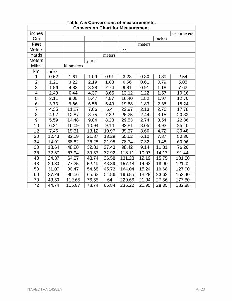
NAVEDTRA 14251A AI-20
Table A-5 Conversions of measurements. Conversion Chart for Measurement
inches centimeters
Cm inches
Feet meters
Meters feet
Yards meters
Meters yards
Miles kilometers
km miles
1 0.62 1.61 1.09 0.91 3.28 0.30 0.39 2.54
2 1.21 3.22 2.19 1.83 6.56 0.61 0.79 5.08
3 1.86 4.83 3.28 2.74 9.81 0.91 1.18 7.62
4 2.49 6.44 4.37 3.66 13.12 1.22 1.57 10.16
5 3.11 8.05 5.47 4.57 16.40 1.52 1.97 12.70
6 3.73 9.66 6.56 5.49 19.68 1.83 2.36 15.24
7 4.35 11.27 7.66 6.4 22.97 2.13 2.76 17.78
8 4.97 12.87 8.75 7.32 26.25 2.44 3.15 20.32
9 5.59 14.48 9.84 8.23 29.53 2.74 3.54 22.86
10 6.21 16.09 10.94 9.14 32.81 3.05 3.93 25.40
12 7.46 19.31 13.12 10.97 39.37 3.66 4.72 30.48
20 12.43 32.19 21.87 18.29 65.62 6.10 7.87 50.80
24 14.91 38.62 26.25 21.95 78.74 7.32 9.45 60.96
30 18.64 48.28 32.81 27.43 98.42 9.14 11.81 76.20
36 22.37 57.94 39.37 32.92 118.11 10.97 14.17 91.44
40 24.37 64.37 43.74 36.58 131.23 12.19 15.75 101.60
48 29.83 77.25 52.49 43.89 157.48 14.63 18.90 121.92
50 31.07 80.47 54.68 45.72 164.04 15.24 19.68 127.00
60 37.28 96.56 65.62 54.86 196.85 18.29 23.62 152.40
70 43.50 112.65 76.55 64 229.66 21.34 27.56 177.80
72 44.74 115.87 78.74 65.84 236.22 21.95 28.35 182.88

NAVEDTRA 14251A AI-21
Table A-6 — Cubic conversion chart. Cubic Conversion Chart
Cubic Meters
Cubic Feet Cubic Yard
Cubic Yard Cubic
Meters
Cubic Feet Cubic
Meters
Cubic Inches
Cubic Centimeters
1 16.39 0.028 0.76 35.3 1.31
2 32.77 0.057 1.53 70.6 2.62
3 49.16 0.085 2.29 105.9 3.92
4 65.55 0.113 3.06 141.3 5.23
5 81.94 0.142 3.82 176.6 6.54
6 98.32 0.170 4.59 211.9 7.85
7 114.71 0.198 5.35 247.2 9.16
8 131.10 0.227 6.12 282.5 10.46
9 147.48 0.255 6.88 317.8 11.77
10 163.87 0.283 7.65 353.1 13.07
20 327.74 0.566 15.29 706.3 26.16
30 491.61 0.850 29.94 1059.4 39.24
40 655.48 1.133 30.58 1412.6 52.32
50 819.35 1.416 38.23 1765.7 65.40
60 983.22 1.700 45.87 2118.9 78.48
70 1174.09 1.982 53.52 2472.0 91.56
80 1310.96 2.265 61.16 2825.2 104.63
90 1474.84 2.548 68.81 3178.3 117.71
100 1638.71 2.832 76.46 3531.4 130.79
Example: 3 cu. Yd = 2.29 cu. M Volume: The cubic meter is the only common dimension used for measuring the volume of solids in the metric system.

NAVEDTRA 14251A AI-22
Table A-7 — Gallon and liter conversion chart.
Gallon Liter Gallon Liter Gallon Liter
.1 .38 1 3.79 10 37.85
.2 .76 2 7.57 20 57.71
.3 1.14 3 11.36 30 113.56
.4 1.51 4 15.14 40 151.42
.5 1.89 5 18.93 50 189.27
.6 2.27 6 22.71 60 227.12
.7 2.65 7 26.50 70 264.98
.8 3.03 8 30.28 80 302.83
.9 3.41 9 34.07 90 340.69 NOTE: 1 us Gallon = 3.785412 Liters 100 us Gallons = 378.5412 Liters
Table A-8 — Weight conversion chart.
Weight Conversion Chart
Ounces Grams
Grams Ounces
Pounds Kilograms
Kilograms Pounds
Short Ton Metric
Ton
Metric Ton
Short Ton
1 1.10 0.91 2.20 0.45 0.04 28.1
2 2.20 1.81 4.41 0.91 0.07 56.7
3 3.31 2.72 6.61 1.36 0.11 85.0
4 4.41 3.63 8.82 1.81 0.14 113.4
5 5.51 4.54 11.02 2.67 0.18 141.8
6 6.61 5.44 13.23 2.72 0.21 170.1
7 7.72 6.35 15.43 3.18 0.25 198.4
8 8.82 7.26 17.64 3.63 0.28 226.8
9 9.92 8.16 19.81 4.08 0.32 255.2
10 11.02 9.07 22.05 4.54 0.35 283.5
16 17.63 14.51 35.27 7.25 0.56 453.6
20 22.05 18.14 44.09 9.07 0.71 567.0
30 33.07 27.22 66.14 13.61 1.06 850.5
40 44.09 36.29 88.14 18.14 1.41 1134.0
50 55.12 45.36 110.23 22.68 1.76 1417.5
60 66.14 54.43 132.28 27.22 2.12 1701.0
70 77.16 63.50 154.32 31.75 2.17 1981.5
80 88.18 72.57 176.37 36.29 2.82 2268.0
90 99.21 81.65 198.42 40.82 3.17 2551.5
100 110.20 90.72 220.46 45.36 3.53 2835.0 NOTE: 1 pound = 0.4535925 KG; 1 US Short Ton = 2,000 pounds; and 1 Metric Ton = 1,000 KG

NAVEDTRA 14251A AI-23
Effective Value = 0.707 x Peak Value
Average Value = 0.637 x Peak Value
Peak Value = 1.414 x Effective Value
Effective Value = 1.11 x Average Value
Peak Value = 1.57 x Average Value
Average Value = 0.9 x Effective Value
FORMULAS
Conversion Factors and Constants Sinusoidal Voltages and Currents
3.14 26.28
2 9.87 (2)2
39.5
2.718 2 1.414
3 1.732 LOG = 0.497
Temperature
(F to C) C = 5/9 (F – 32)
(C to F) F = 9/5 C = 32
(C to K) K = C + 73
Power
1 kilowatt = 1.341 horsepower
1 horsepower = 746 watts
Trigonometric Formulas
sin A = a
Opposite Side
c Hypotenuse
cos A = b
Adjacent Side
c Hypotenuse
tan A = a
Opposite Side
b Adjacent Side Figure A-12
cot A = b
Adjacent Side — Trapezoid. a Opposite Side
Ohm’s Law- Direct Current Ohm’s Law- Alternating Current
Figure A-13 —
Direct Current.
Figure A-14 — Alternating
Current.

NAVEDTRA 14251A AI-24
1,000 P F P P E
I =
P E
P PF
P kVA =
2 x E x I kW kW
E x PF I x PF E x I 1,000 P F
P L P L
3 3
Speed vs. Poles Formulas
F = NP
N = 120
F 120 P =
P
F 120
N
F = frequency
N= speed of rotation
P = number of poles
120 = time constant
Power Factor
PF = actual power
watts
kW
R apparent power volts x amperes kVA Z
PF P
E x I
kVA x PF
lanced
Power: Three-Phase Balanced Wye or Delta Circuits
P = 1.732 x E x I x PF VA = 1.732 x E x I
E = P
0.577 x P
PF x 1.73 x I PF x I
I = P
0.577 x P
PF x 1.73 x E PF x E
PF = P
0.577 x P
PF x 1.73 x E I x E
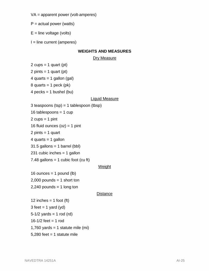
NAVEDTRA 14251A AI-25
VA = apparent power (volt-amperes)
P = actual power (watts)
E = line voltage (volts)
I = line current (amperes)
2 cups = 1 quart (pt)
2 pints = 1 quart (pt)
4 quarts = 1 gallon (gal)
8 quarts = 1 peck (pk)
4 pecks = 1 bushel (bu)
WEIGHTS AND MEASURES
Dry Measure
Liquid Measure
3 teaspoons (tsp) = 1 tablespoon (tbsp)
16 tablespoons = 1 cup
2 cups = 1 pint
16 fluid ounces (oz) = 1 pint
2 pints = 1 quart
4 quarts = 1 gallon
31.5 gallons = 1 barrel (bbl)
231 cubic inches = 1 gallon
7.48 gallons = 1 cubic foot (cu ft)
16 ounces = 1 pound (lb)
2,000 pounds = 1 short ton
2,240 pounds = 1 long ton
12 inches = 1 foot (ft)
3 feet = 1 yard (yd)
5-1/2 yards = 1 rod (rd)
16-1/2 feet = 1 rod
1,760 yards = 1 statute mile (mi)
5,280 feet = 1 statute mile
Weight
Distance
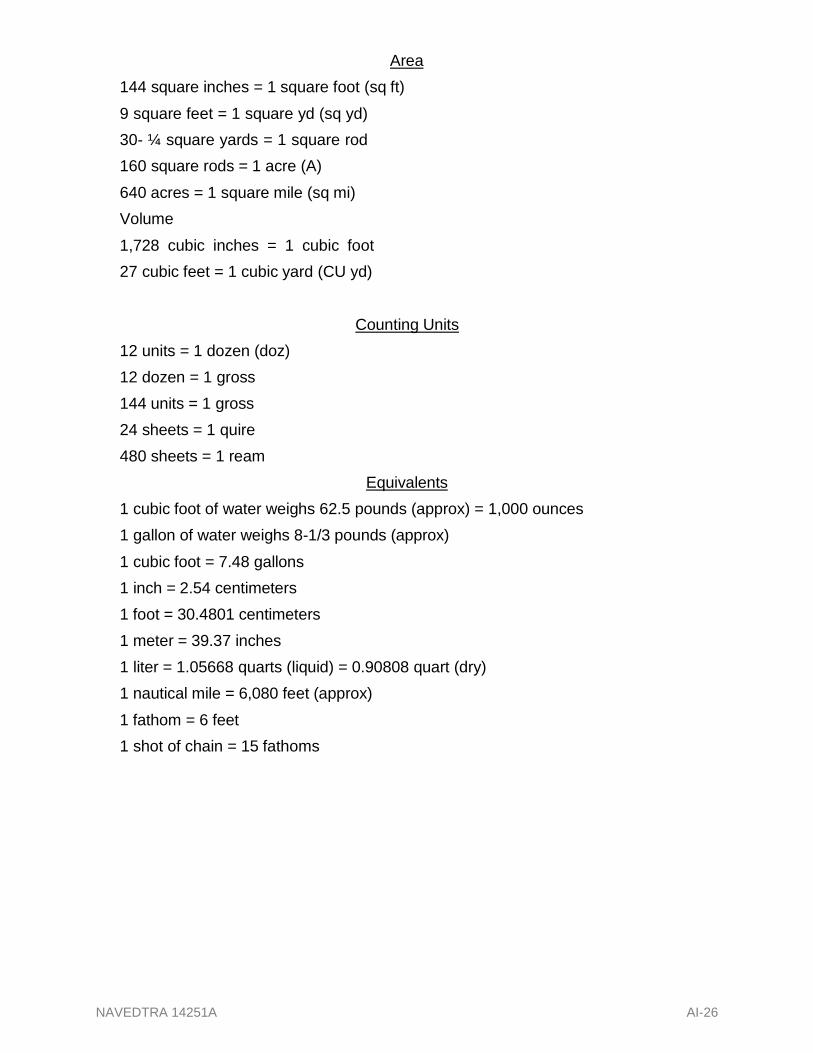
NAVEDTRA 14251A AI-26
Area
144 square inches = 1 square foot (sq ft)
9 square feet = 1 square yd (sq yd)
30- ¼ square yards = 1 square rod
160 square rods = 1 acre (A)
640 acres = 1 square mile (sq mi)
Volume
1,728 cubic inches = 1 cubic foot
27 cubic feet = 1 cubic yard (CU yd)
12 units = 1 dozen (doz)
12 dozen = 1 gross
144 units = 1 gross
24 sheets = 1 quire
480 sheets = 1 ream
Counting Units
Equivalents
1 cubic foot of water weighs 62.5 pounds (approx) = 1,000 ounces
1 gallon of water weighs 8-1/3 pounds (approx)
1 cubic foot = 7.48 gallons
1 inch = 2.54 centimeters
1 foot = 30.4801 centimeters
1 meter = 39.37 inches
1 liter = 1.05668 quarts (liquid) = 0.90808 quart (dry)
1 nautical mile = 6,080 feet (approx)
1 fathom = 6 feet
1 shot of chain = 15 fathoms
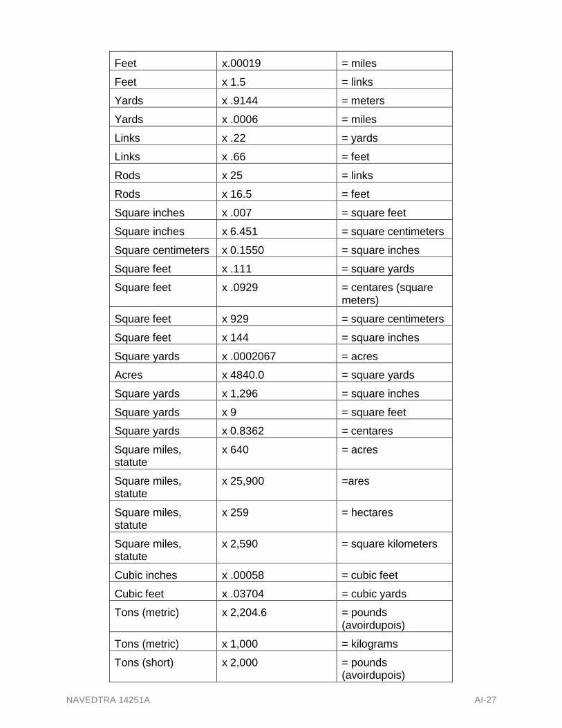
NAVEDTRA 14251A AI-27
Feet x.00019 = miles
Feet x 1.5 = links
Yards x .9144 = meters
Yards x .0006 = miles
Links x .22 = yards
Links x .66 = feet
Rods x 25 = links
Rods x 16.5 = feet
Square inches x .007 = square feet
Square inches x 6.451 = square centimeters
Square centimeters x 0.1550 = square inches
Square feet x .111 = square yards
Square feet x .0929 = centares (square meters)
Square feet x 929 = square centimeters
Square feet x 144 = square inches
Square yards x .0002067 = acres
Acres x 4840.0 = square yards
Square yards x 1,296 = square inches
Square yards x 9 = square feet
Square yards x 0.8362 = centares
Square miles, statute
x 640 = acres
Square miles, statute
x 25,900 =ares
Square miles, statute
x 259 = hectares
Square miles, statute
x 2,590 = square kilometers
Cubic inches x .00058 = cubic feet
Cubic feet x .03704 = cubic yards
Tons (metric) x 2,204.6 = pounds (avoirdupois)
Tons (metric) x 1,000 = kilograms
Tons (short) x 2,000 = pounds (avoirdupois)
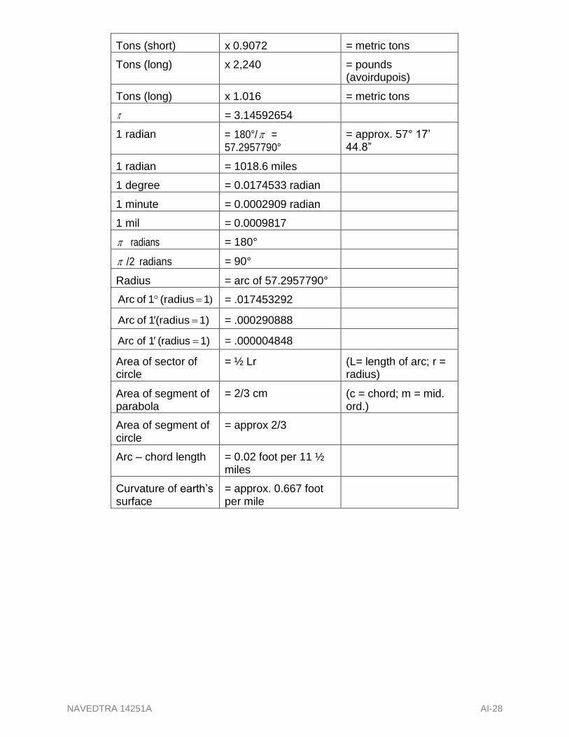
NAVEDTRA 14251A AI-28
Tons (short) x 0.9072 = metric tons
Tons (long) x 2,240 = pounds (avoirdupois)
Tons (long) x 1.016 = metric tons
= 3.14592654
1 radian = 180°/ = 57.2957790°
= approx. 57° 17’ 44.8”
1 radian = 1018.6 miles
1 degree = 0.0174533 radian
1 minute = 0.0002909 radian
1 mil = 0.0009817
radians = 180°
/2 radians = 90°
Radius = arc of 57.2957790°
Arc of 1(radius 1) = .017453292
Arc of 1(radius 1) = .000290888
Arc of 1(radius 1) = .000004848
Area of sector of circle
= ½ Lr (L= length of arc; r = radius)
Area of segment of parabola
= 2/3 cm (c = chord; m = mid. ord.)
Area of segment of circle
= approx 2/3
Arc – chord length = 0.02 foot per 11 ½ miles
Curvature of earth’s surface
= approx. 0.667 foot per mile

NAVEDTRA 14251A AII-1
APPENDIX II
Hand Signals

NAVEDTRA 14251A AII-2

NAVEDTRA 14251A AII-3

NAVEDTRA 14251A AII-4
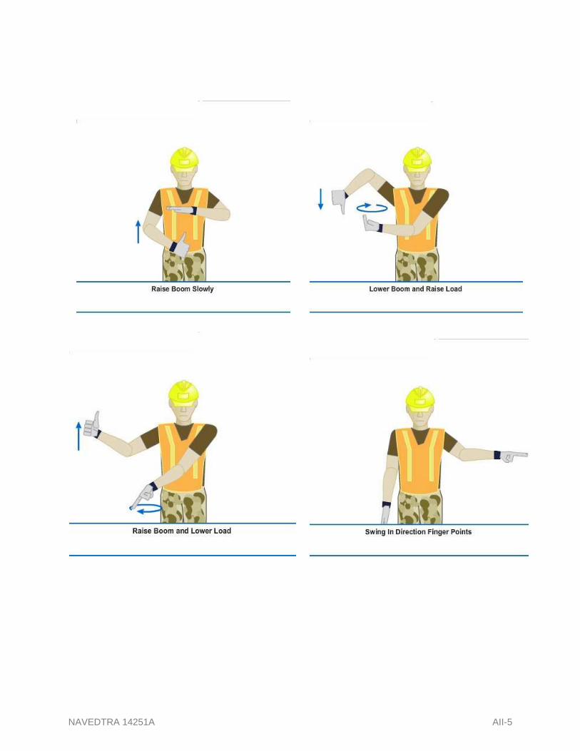
NAVEDTRA 14251A AII-5

NAVEDTRA 14251A AII-6

NAVEDTRA 14251A AII-7

NAVEDTRA 14251A AII-8

NAVEDTRA 14251A AII-9

NAVEDTRA 14251A AIII-1
APPENDIX II,
COMMON CONSTRUCTION SYMBOLOGY

NAVEDTRA 14251A AIII-2

NAVEDTRA 14251A AIII-3

NAVEDTRA 14251A AIII-4

NAVEDTRA 14251A AIII-5

NAVEDTRA 14251A AIII-6

NAVEDTRA 14251A AIII-7

NAVEDTRA 14251A AIII-8

NAVEDTRA 14251A AIII-9

NAVEDTRA 14251A AIII-10

NAVEDTRA 14251A AIII-11

NAVEDTRA 14251A AIII-12

NAVEDTRA 14251A AIII-13

NAVEDTRA 14251A AIII-14

NAVEDTRA 14251A AIII-15

NAVEDTRA 14251A AIII-16

NAVEDTRA 14251A AIII-17
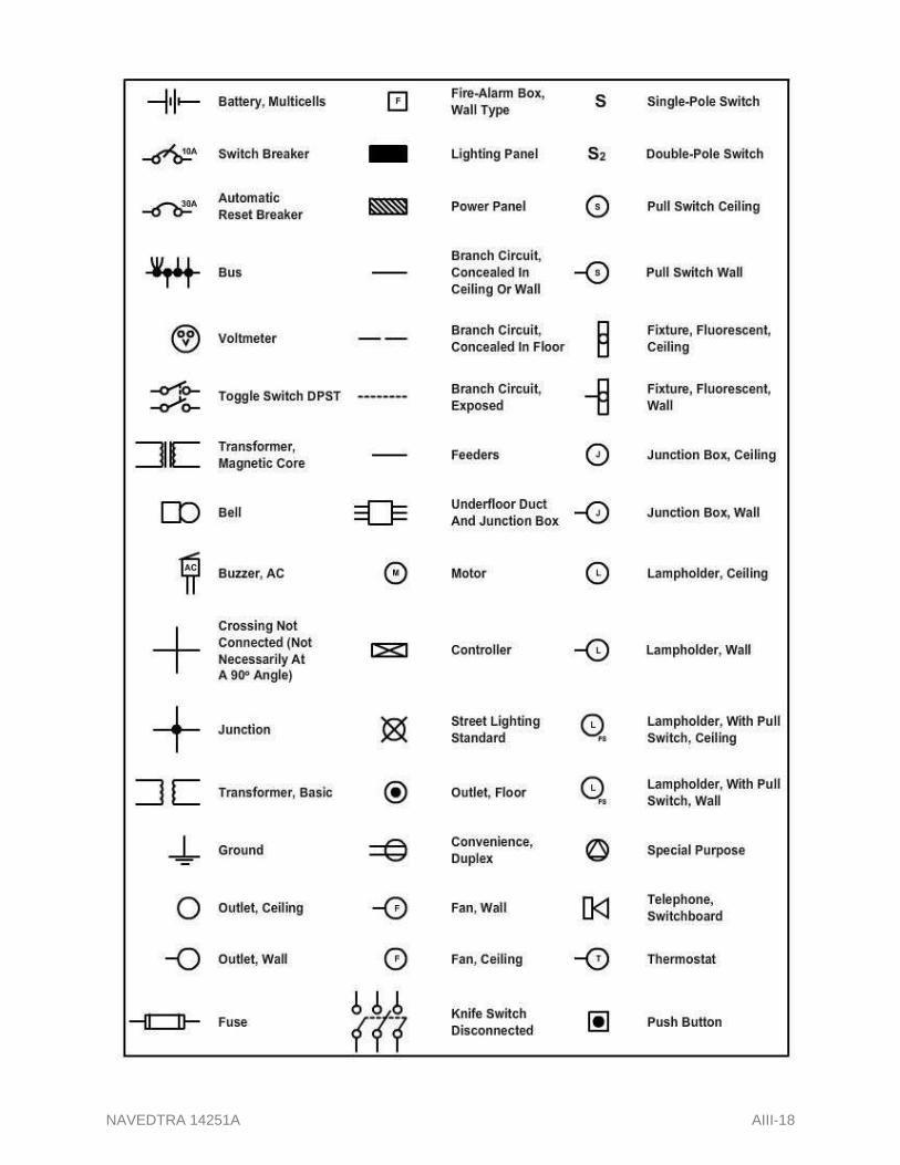
NAVEDTRA 14251A AIII-18

NAVEDTRA 14251A AIII-19
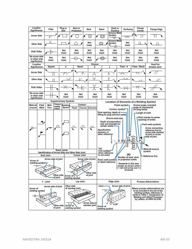
NAVEDTRA 14251A AIII-20

NAVEDTRA 14251A AIII-21

NAVEDTRA 14251A AIII-22

NAVEDTRA 14251A AIII-23

NAVEDTRA 14251A AIII-24

NAVEDTRA 14251A AIII-25

NAVEDTRA 14251A AIII-26