O-Pump | Automated Wireless Water Distribution System (Español)

Wireless multiplex Energy Distribution Management System
Er.Rakesh Kumar Kumawat
1 | P a g e Project report Final year electrical engineering
CHAPTER- 1
OVERVIEW OF WIRELESS MULTIPLEX ENERGY DISTRIBUTION
MANAGEMENT SYSTEM
INTRODUCTION:-
This project is a solution to remote detection of illegal electricity. By this project we prevent
illegal usage of electricity and remote detection of illegal usage of electricity. We can achieve
this with the help of four energy meters. The energy meters used are electronic energy meters for
high accuracy. The electronic energy meters are interfaced to a relay circuit so that the energy
count can be converted into pulses. Main energy meter delivers the power continuously to the
three sub meters. The main meter is interfaced to the PC serial port using the relay circuit so that
the total energy count can be calculated. Likewise the sub meters are interfaced by the relay
circuit to an encoder circuit which converts multiple bit pulse pattern into a single serial stream,
which is then wirelessly transmitted. The receiver at the main meter side receives the wireless
signals and the signals are decoded using an appropriate decoder and fed to the pc. The PC now
has the reading of the total energy count and the energy consumed by individual units. By
comparing the data of main energy meter and three sub-meters, detection of illegal usage of
electricity is achieved. For remote detection of illegal usage of electricity all the energy count is
shown on computer. Thus energy distribution can be managed in a very simple way.
The block diagram of multiplex energy distribution management system is shown. As per the
block diagram this multiplex energy distribution management system mainly contains four
energy meters. One is the main meter and others are sub-meters. The main meter is connected to
relay, which is connected to the parallel port. All the sub-meters are connected to the load in
series and also connected to the relay as shown in block diagram. The entire relay connected to
the encoder and this encoder is connected to RF transmitter. Other side as shown in block
diagram a decoder and RF receiver is connected to the parallel port which in turn gives the
readings on the PC.

Wireless multiplex Energy Distribution Management System
Er.Rakesh Kumar Kumawat
2 | P a g e Project report Final year electrical engineering
Parallel
Port
Fig 1: Block Diagram of Multiplex Energy Distribution Management System
.
Sub-Meter 1
Load 1
Main Meter
Relay
Encoder
RF Transmitter
RF Receiver
Decoder
Relay
Relay
Load 3
Sub-Meter 3
Load 2
Sub-Meter 2
Relay
Main Meter - Sub-Meter1- Sub-Meter1- Sub-Meter1- T&D Losses- % T&D Losses-

Wireless multiplex Energy Distribution Management System
Er.Rakesh Kumar Kumawat
3 | P a g e Project report Final year electrical engineering
CHAPTER 2
DRISCRIPTION OF COMPONENT
LIST OF COMPONENTS:-
1. P-N Diodes (1N4007)
2. NPN Transistors (BC547)
3. Voltage Regulator (LM7805)
4. Photo transistor optocoupler (MCT2E)
5. Capacitor (1000µF,1µF)
6. Relay
7. Transformer (220v/12v)
8. Rf module
9. IC-MAX232
10. IC-HT12E(Encoder)
11. IC-HT12D(Decoder)
12. IC-PCI16F73(Microcontroller)
13. Energy meter

Wireless multiplex Energy Distribution Management System
Er.Rakesh Kumar Kumawat
4 | P a g e Project report Final year electrical engineering
2.1) DIODES:-
Diodes are components that allow current to flow in only one direction. They have a positive
side (leg) and a negative side. When the voltage on the positive leg is higher than on the negative
leg then current flows through the diode (the resistance is very low). When the voltage is lower
on the positive leg than on the negative leg then the current does not flow (the resistance is very
high). The negative leg of a diode is the one with the line closest to it. It is called the cathode.
The positive end is called the anode.
Fig 02: Diode
Usually when current is flowing through a diode, the voltage on the positive leg is 0.65 volts
higher than on the negative leg.
2.2). TRANSISTOR:-
Transistors are basic components in all of today's electronics. They are just simple switches that
we can use to turn things on and off. Even though they are simple, they are the most important
electrical component. For example, transistors are almost the only components used to build a
Pentium processor. A single Pentium chip has about 3.5 million transistors. The ones in the
Pentium are smaller than the ones we will use but they work the same way.

Wireless multiplex Energy Distribution Management System
Er.Rakesh Kumar Kumawat
5 | P a g e Project report Final year electrical engineering
Fig 03: Transistor
The transistor has three legs, the Collector (C), Base (B), and Emitter (E). Sometimes they are
labeled on the flat side of the transistor. Transistors always have one round side and one flat side.
If the round side is facing you, the Collector leg is on the left, the Base leg is in the middle, and
the Emitter leg is on the right. The following symbol is used in circuit drawings (schematics) to
represent a transistor.
Fig 04: Transistor symbol
2.3) POWER SUPPLY:-
Power supply can be defined as electronic equipment, which is a stable source of D.C. power
for electronic circuits.
Power supply can be classified into two major categories: -
A) UNREGULATED POWER SUPPLY
B) REGULATED POWER SUPPLY

Wireless multiplex Energy Distribution Management System
Er.Rakesh Kumar Kumawat
6 | P a g e Project report Final year electrical engineering
A) UNREGULATED POWER SUPPLY: -
These power supplies, supply power to the load but do not take into variation of power supply output voltage
or current with respect to the change in A.C. mains voltage, load current or temperature variations. In other
words, we can say that the output voltage or current of an unregulated power supply changes with the change
in A.C.mains voltage, load current and temperature.
B) REGULATED POWER SUPPLY: -
These power supplies are regulated over the change in source voltage or load current i.e. its output remains
stable. Regulated power supplies are of two types: -
a) Current regulated power supplies
These are constant current supplies in spite of change in load or input voltage.
b) Voltage regulated power supplies
These supplies supply constant output voltage with respect to the variation in load or source input
voltage.
Fig 05: Block diagram of unregulated power supply
A .C. INPUT LOAD RECTIFIER FILTER

Wireless multiplex Energy Distribution Management System
Er.Rakesh Kumar Kumawat
7 | P a g e Project report Final year electrical engineering
Fig 07: Regulated power supply with half wave rectifier and IC-7805
Here diode D1, D2, D3 and D4 forms half wave rectifier. Capacitor C1 is filtering capacitor. IC-
7805 is used for voltage regulation. Capacitor C2 is used for bypassing, if any ripples are present
then it eliminates those ripples.
As IC-7805 is used so it gives 5v dc regulated voltage ideally. If we take 12volts transformer
then we will get 5v at output. Thus voltage is regulated.
C20.1uF
IN
COM
OUT
C1
1000uFD4D3D2D1
T110TO1
VL Vdc Vac A.C.
INPUT
LOAD REGULATOR FILTER RECTIFIER
FIER Fig 06: Block diagram of regulated power supply
OUTPUT

Wireless multiplex Energy Distribution Management System
Er.Rakesh Kumar Kumawat
8 | P a g e Project report Final year electrical engineering
2.4) RELAYS:-
A relay is usually an electromechanical device that is actuated by an electrical current. The
current flowing in one circuit causes the opening or closing of another circuit. Relays are like
remote control switches and are used in many applications because of their relative simplicity,
long life, and proven high reliability. They are used in a wide variety of applications throughout
industry, such as in telephone exchanges, digital computers and automation systems.
How do relays work?
All relays contain a sensing unit, the electric coil, which is powered by AC or DC current. When
the applied current or voltage exceeds a threshold value, the coil activates the armature, which
operates either to close the open contacts or to open the closed contacts. When a power is
supplied to the coil, it generates a magnetic force that actuates the switch mechanism. The
magnetic force is, in effect, relaying the action from one circuit to another. The first circuit is
called the control circuit; the second is called the load circuit. A relay is usually an
electromechanical device that is actuated by an electrical current.
The current flowing in one circuit causes the opening or closing of another circuit.
Fig 08: Relay circuit

Wireless multiplex Energy Distribution Management System
Er.Rakesh Kumar Kumawat
9 | P a g e Project report Final year electrical engineering
Types of relays:-
There are two basic classifications of relays:
A) Electromechanical Relay
B) Solid State Relay.
Electromechanical relays have moving parts, whereas solid state relays have no moving parts.
Advantages of Electromechanical relays include lower cost, no heat sink is required, multiple
poles are available, and they can switch AC or DC with equal ease.
A) Electromechanical Relays:-
a) General Purpose Relay: -
The general-purpose relay is rated by the amount of current its switch contacts can handle. Most
versions of the general-purpose relay have one to eight poles and can be single or double throw.
These are found in computers, copy machines, and other consumer electronic equipment and
appliances.
Fig 09: General Purpose Relay

Wireless multiplex Energy Distribution Management System
Er.Rakesh Kumar Kumawat
10 | P a g e Project report Final year electrical engineering
b) Power Relay: -
The power relay is capable of handling larger power loads – 10-50 amperes or more. They are
usually single-pole or double-pole units.
Fig 10: Power Relay
c) Contractor:-
A special type of high power relay, it‟s used mainly to control high voltages and currents in
industrial electrical applications. Because of these high power requirements, contactors always
have double-make contacts.
d) Time-Delay Relay: -
The contacts might not open or close until sometime interval after the coil has been energized.
This is called delay-on-operate. Delay On-release means that the contacts will remain in their
actuated position until some interval after the power has been removed from the coil. A third
delay is called interval timing. Contacts revert to their alternate position at a specific interval of
time after the coil has been energized. The timing of these actions may be a fixed parameter of
the relay, or adjusted by a knob on the relay itself, or remotely adjusted through an external
circuit.

Wireless multiplex Energy Distribution Management System
Er.Rakesh Kumar Kumawat
11 | P a g e Project report Final year electrical engineering
B) Solid State Relays:-
Fig 11: Solid State Relays
These active semiconductor devices use light instead of magnetism to actuate a switch. The light
comes from an LED, or light emitting diode. When control power is applied to the device‟s
output, the light is turned on and shines across an open space.
On the load side of this space, a part of the device senses the presence of the light, and triggers a
solid state switch that either opens or closes the circuit under control. Often, solid state relays
are used where the circuit under control must be protected from the introduction of electrical
noises.
Advantages of Solid State Relays include low EMI/RFI, long life, no moving parts, no contact
bounce, and fast response. The drawback to using a solid state relay is that it can only
accomplish single pole switching.

Wireless multiplex Energy Distribution Management System
Er.Rakesh Kumar Kumawat
12 | P a g e Project report Final year electrical engineering
2.5) CAPACITOR:-
Now suppose you want to control how the current in your circuit changes (or not changes) over
time. Now why would you? Well radio signals require very fast current changes. Robot motors
cause current fluctuations in your circuit which you need to control. What do you do when
batteries cannot supply current as fast as you circuit drains them? How do you prevent sudden
current spikes that could fry your robot circuitry? The solution to this is capacitors.
Fig 12: capacitor
Capacitors are like electron storage banks. If your circuit is running low, it will deliver electrons
to your circuit.In our water analogy, think of this as a water tank with water always flowing in,
but with drainage valves opening and closing. Since capacitors take time to charge, and time to
discharge, they can also be used for timing circuits. Timing circuits can be used to generate
signals such as PWM or be used to turn on/off motors in solar powered BEAM robots. Quick
note, some capacitors are polarized, meaning current can only flow one direction through them.
If a capacitor has a lead that is longer than the other, assume the longer lead must always connect
to positive.
Fig 13: capacitor electrical symbol

Wireless multiplex Energy Distribution Management System
Er.Rakesh Kumar Kumawat
13 | P a g e Project report Final year electrical engineering
2.6) THE LED:-
An LED is the device shown above. Besides red, they can also be yellow, green and blue. The
letters LED stand for Light Emitting Diode. The important thing to remember about diodes
(including LEDs) is that current can only flow in one direction.
Fig 14: Led
2.7) PRINTED CIRCUIT BOARDS:-
The use of miniaturization and sub miniaturization in electronic equipment design has been
responsible for the introduction of a new technique in inters component wiring and assembly that
is popularly known as printed circuit.
The printed circuit boards (PCBs) consist of an insulating substrate material with metallic
circuitry photo chemically formed upon that substrate. Thus PCB provides sufficient mechanical
support and necessary electrical connections for an electronic circuit.
Advantages of printed circuit boards: -
i. Circuit characteristics can be maintained without introducing variations inter circuit
capacitance.
ii. Wave soldering or vapour phase reflow soldering can mechanize component wiring and
assembly.
iii. Mass production can be achieved at lower cost.
iv. The size of component assembly can be reduced with corresponding decrease in weight

Wireless multiplex Energy Distribution Management System
Er.Rakesh Kumar Kumawat
14 | P a g e Project report Final year electrical engineering
.
Types of PCB‟s: -
There are four major types of PCB‟s: -
i. Single sided PCB: - In this, copper tracks are on one side of the board, and are the
simplest form of PCB. These are simplest to manufacture thus have low production cost.
ii. Double sided PCB:- In this, copper tracks are provided on both sides of the substrate. To
achieve the connections between the boards, hole plating is done, which increase the
manufacturing complexity.
iii. Multilayered PCB: - In this, two or more pieces of dielectric substrate material with
circuitry formed upon them are stacked up and bonded together. Electrically connections
are established from one side to the other and to the layer circuitry by drilled holes, which
are subsequently plated through copper.
iv. Flexible PCB: - Flexible circuit is basically a highly flexible variant of the conventional
rigid printed circuit board theme.
PCB Manufacturing Process: -
There are a number of different processes, which are used to manufacture a PCB, which is ready
for component assembly, from a copper clad base material. These processes are as follows
i. Preprocessing: - This consists of initial preparation of a copper clad laminate ready for
subsequent processing. Next is to drill tooling holes. Passing a board through rollers
performs cleaning operation.
ii. Photolithography: - This process for PCBs involves the exposure of a photo resist
material to light through a mask. This is used for defining copper track and land patterns.
iii. Etching: - The etching process is performed by exposing the surface of the board to an
etchant solution which dissolves away the exposed copper areas .The different solutions
used are: FeCl, CuCl, etc.

Wireless multiplex Energy Distribution Management System
Er.Rakesh Kumar Kumawat
15 | P a g e Project report Final year electrical engineering
iv. Drilling: - Drilling is used to create the component lead holes and through holes in a PCB
.The drilling can be done before or after the track areas have been defined.
v. Solder Masking: - It is the process of applying organic coatings selectively to those areas
where no solder wettings is needed .The solder mask is applied by screen-printing.
vi. Metal Plating: - The plating is done to ensure protection of the copper tracks and
establish connection between different layers of multiplayer boards. PCBs are stacked
before being taken for final assembly of components .The PCB should retain its solder
ability.
vii. Bare-Board Testing: - Each board needs to ensure that the required connections exist, that
there are no short circuits and holes are properly placed .The testing usually consists of
visual inspection and continuity testing.
2.8) ENERGY METER:-
A meter is any device built to accurately detect and display an electrical quantity in a form
readable by a human being. Usually this "readable form" is visual: motion of a pointer on a scale,
a series of lights arranged to form a "bargraph," or some sort of display composed of numerical
figures. In the analysis and testing of circuits, there are meters designed to accurately measure
the basic quantities of voltage, current, and resistance. There are many other types of meters as
well, but this chapter primarily covers the design and operation of the basic three. Most modern
meters are "digital" in design, meaning that their readable display is in the form of numerical
digits. Older designs of meters are mechanical in nature, using some kind of pointer device to
show quantity of measurement. In either case, the principles applied in adapting a display unit to
the measurement of (relatively) large quantities of voltage, current, or resistance are the same?
The display mechanism of a meter is often referred to as a movement, borrowing from its
mechanical nature to move a pointer along a scale so that a measured value may be read. Though
modern digital meters have no moving parts, the term "movement" may be applied to the same
basic device performing the display function.

Wireless multiplex Energy Distribution Management System
Er.Rakesh Kumar Kumawat
16 | P a g e Project report Final year electrical engineering
CHAPTER 3
RF TRANSMITTER AND RECEIVER MODULE
These modules are now widely and cheaply available with the operating frequency of 433 MHz.
The transmitter module accepts serial data. The encoder IC takes in parallel data at the TX side
packages it into serial format and then transmits it with the help of a RF transmitter module. At
the RX end, the decoder IC receives the signal via the RF receiver module, decodes the serial
data and reproduces the original data in the parallel format.
Features:-
i. Range in open space (Standard Conditions): 100 Meters
ii. RX Receiver Frequency: 433 MHz
iii. Low Power Consumption
iv. Easy For Application
v. RX Operating Voltage: 5V
vi. TX Frequency Range: 433.92 MHz
Fig 15. 433 MHz Transmitter

Wireless multiplex Energy Distribution Management System
Er.Rakesh Kumar Kumawat
17 | P a g e Project report Final year electrical engineering
Fig 16. 433 MHz RF Receiver
3.1) TX433 (TRANSMISSION MODULE):-
The TX433 wireless RF transmitter uses on/off keying to transmit data to the matching receiver,
RX433. The data input “keys” the saw resonator in the transmitter when the input is +3 volts or
greater, AM modulating the data onto the 433 MHz carrier. The data is then demodulated by the
receiver, which accurately reproduces the original data. The data input is CMOS level
Compatible when the unit is run on +5 volts.
When driving with a CMOS input, there must be enough level to achieve at least 3V on the data
input, 5V is preferable. This is due to the start-up time of the oscillator needing to be fast to
accurately reproduce your data. If the voltage is too low, the oscillator will not start fast enough
to accurately reproduces your data, especially at higher data rates. Luckily not much drive is
needed, so this should be easy since it is 22K ohms of load. Almost any CMOS output will drive
this without any problems. There are some CMOS outputs which have very little drive capability

Wireless multiplex Energy Distribution Management System
Er.Rakesh Kumar Kumawat
18 | P a g e Project report Final year electrical engineering
which may not work, so testing the voltage at the data input may be a wise choice if you are
having problems.
3.2) RX433 (RECEIVER MODULE):-
The receiver shown in Figure also contains just one transistor. It is biased to act as a regenerative
oscillator, in which the received antenna signal causes the transistor to switch to high
amplification, thereby automatically arranging the signal detection. Next, the „raw‟ demodulated
signal is amplified and shaped-up by op-amps. The result is a fairly clean digital signal at the
output of the receiver. The logic high level is at about 2/3 of the supply voltage, i.e., between 3 V
and 4.5 V.
The range of the simple system shown in Figures is much smaller than that of more expensive
units, mainly because of the low transmit power (approx. 1 mW) and the relative insensitivity
and wide-band nature of the receiver. Moreover, amplitude-modulated noise is not suppressed in
any way.
3.3) ANTENNA CONSIDERATIONS:-
The simplest antenna consists of a piece of wire approximately 6 to 7 inches long. If you desire
more range you can try a ground plane antenna or a Yagi such as the Ramsey 400-4 model. The
antenna should be tuned for the 433 MHz band for best operation.
Having two Yagi antennas, one for the transmitter and one for the receiver will allow you to
extend the range considerably, but since they are directional, this would be best for if your
receiver and transmitter are in fixed positions.
3.4) HT12E ENCODERS:-
General Description:-
The 212 encoders are a series of CMOS LSIs for remote control system applications. They are
capable of encoding information which consistsof N address bits and 12_N data bits. Each
address data input can be set to one of the two logic states. The programmed addresses/data are

Wireless multiplex Energy Distribution Management System
Er.Rakesh Kumar Kumawat
19 | P a g e Project report Final year electrical engineering
transmitted together with the header bits via an RF or an infrared transmission medium upon
receipt of a trigger signal. The capability to select a TE trigger on the HT12E or a DATA trigger
on the HT12A further enhances the application flexibility of the 212 series of encoders. The
HT12A additionally provides a 38kHz carrier for infrared systems.
Features:-
i. Operating voltage
ii. 2.4V~12V for the HT12E
iii. Low power and high noise immunity CMOS technology
iv. Low standby current: 0.1_A (typ.) at VDD=5V
v. HT12A with a 38kHz carrier for infrared transmission medium
vi. Minimum transmission word
vii. Data code has positive polarity
viii. Minimal external components
ix. HT12E: 18-pin DIP/20-pin SOP package
Applications:-
i. Burglar alarm system
ii. Smoke and fire alarm system
iii. Garage door controllers
iv. Car door controllers
v. Car alarm system
vi. Security system
vii. Cordless telephones
viii. Other remote control systems

Wireless multiplex Energy Distribution Management System
Er.Rakesh Kumar Kumawat
20 | P a g e Project report Final year electrical engineering
Fig 17: HT12E Encoder
3.5) HT12D DECODERS:-
General Description:-
The decoders are a series of CMOS LSIs for remote control system applications. They are paired
with Holtek series of encoders (refer to the encoder/decoder cross reference table). For proper
operation, a pair of encoder/decoder with the same number of addresses and data format should
be chosen. The decoders receive serial addresses and data from a programmed 2 12 series of
encoders that are transmitted by a carrier using an RF or an IR transmission medium. They
compare the serial input data three times continuously with their local addresses. If no error or
unmatched codes are found, the input data codes are decoded and then transferred to the output
pins. The VT pin also goes high to indicate a valid transmission. The series of decoders are
capable of decoding information‟s that consist of N bits of address and bits of data. Of this

Wireless multiplex Energy Distribution Management System
Er.Rakesh Kumar Kumawat
21 | P a g e Project report Final year electrical engineering
series, the HT12D is arranged to provide 8 address bits and 4 data bits, and HT12F is used to
decode 12
Features:-
i. Operating voltage: 2.4V~12V
ii. Low power and high noise immunity CMOS technology
iii. Low standby current
iv. Capable of decoding 12 bits of information
v. Pair with Holtek series of encoders
vi. Binary address setting
vii. Received codes are checked 3 times
viii. Address/Data number combination
ix. HT12D: 8 address bits and 4 data bits
x. Built-in oscillator needs only 5% resistor
xi. Valid transmission indicator
xii. Easy interface with an RF or an infrared transmission medium Minimal external
components
Applications:-
i. Burglar alarm system
ii. Smoke and fire alarm system
iii. Garage door controllers
iv. Car door controllers
v. Car alarm system
vi. Security system
vii. Cordless telephones
viii. Other remote control systems

Wireless multiplex Energy Distribution Management System
Er.Rakesh Kumar Kumawat
22 | P a g e Project report Final year electrical engineering
Fig 18: HT12D Decoder
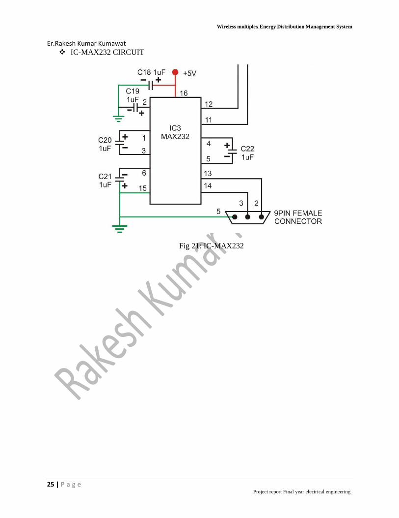
3.6) IC-MAX232:-
The MAX232 is a dual driver/receiver that includes a capacitive voltage generator to supply
TIA/EIA-232F Voltage levels from a single 5-V supply. Each receiver converts TIA/EIA-232-F
inputs to 5-V TTL/CMOS levels. These receivers have a typical threshold of 1.3 V, a typical
hysteresis of 0.5 V, and can accept 30-V inputs. Each driver converts TTL/CMOS input levels
into TIA/EIA-232-F levels. The driver, receiver, and voltage-generator functions are available as
cells in the Texas Instruments Lin ASI library.
Fig 19: IC-MAX232

Wireless multiplex Energy Distribution Management System
Er.Rakesh Kumar Kumawat
23 | P a g e Project report Final year electrical engineering
CIRCUIT DIAGRAM:-
ENCODER CIRCUIT:-
Fig 20: Encoder circuit

Wireless multiplex Energy Distribution Management System
Er.Rakesh Kumar Kumawat
24 | P a g e Project report Final year electrical engineering
DECODER CIRCUIT:-
Fig 21: Decoder circuit
HT12D+PCI16F73
Fig 22:HT12D+PCI16F73
Wireless multiplex Energy Distribution Management System
Er.Rakesh Kumar Kumawat
25 | P a g e Project report Final year electrical engineering
IC-MAX232 CIRCUIT
Fig 21: IC-MAX232

Wireless multiplex Energy Distribution Management System
Er.Rakesh Kumar Kumawat
26 | P a g e Project report Final year electrical engineering
CHAPTER 4
MICROCONTROLER COADING
void main()
{
unsigned int meter1,meter2,meter3,mainmeter;
unsigned int digit1,digit2,digit3,temp;
unsigned int count;
Usart_Init(9600);
meter1=0;
meter2=0;
meter3=0;
mainmeter=0;
count=0;
Usart_Write('M');
Usart_Write('E');
Usart_Write('M');
Usart_Write('D');
Usart_Write('S');
Usart_Write(10);
Usart_Write(13);
while(1)
{
if(PORTC.bit0==0)
Wireless multiplex Energy Distribution Management System
Er.Rakesh Kumar Kumawat
27 | P a g e Project report Final year electrical engineering
{
while(PORTC.bit0==0)
{
}
meter1=meter1+1;
if(meter1>999)
{
meter1=0;
meter2=0;
meter3=0;
mainmeter=0;
}
if(PORTC.bit1==0)
{
while(PORTC.bit1==0)
{
}
meter2=meter2+1;
if(meter2>999)
{
meter1=0;
meter2=0;
meter3=0;
mainmeter=0;
}

Wireless multiplex Energy Distribution Management System
Er.Rakesh Kumar Kumawat
28 | P a g e Project report Final year electrical engineering
}
if(PORTC.bit2==0)
{
while(PORTC.bit2==0)
{
}
meter3=meter3+1;
if(meter3>999)
{
meter1=0;
meter2=0;
meter3=0;
mainmeter=0;
}
}
if(PORTC.bit4==0)
{
while(PORTC.bit4==0)
{
}
mainmeter=mainmeter+1;
if(mainmeter>999)
{
meter1=0;
meter2=0;

Wireless multiplex Energy Distribution Management System
Er.Rakesh Kumar Kumawat
29 | P a g e Project report Final year electrical engineering
meter3=0;
mainmeter=0;
}
}
if(count>1000)
{
temp=meter1;
Usart_Write('M');
Usart_Write('1');
Usart_Write(':');
Usart_Write(' ');
if(temp>=0 && temp<10)
{
Usart_Write(temp+48);
}
else if(temp>=10 && temp<100)
{
digit1=temp%10;
digit2=temp/10;
Usart_Write(digit2+48);
Usart_Write(digit1+48);
}
else if(temp>=100 && temp<1000)
{
digit1=temp%10;

Wireless multiplex Energy Distribution Management System
Er.Rakesh Kumar Kumawat
30 | P a g e Project report Final year electrical engineering
temp=temp/10;
digit2=temp%10;
digit3=temp/10;
Usart_Write(digit3+48);
Usart_Write(digit2+48);
Usart_Write(digit1+48);
}
Usart_Write(10);
Usart_Write(13);
temp=meter2;
Usart_Write('M');
Usart_Write('2');
Usart_Write(':');
Usart_Write(' ');
if(temp>=0 && temp<10)
{
Usart_Write(temp+48);
}
else if(temp>=10 && temp<100)
{
digit1=temp%10;
digit2=temp/10;
Usart_Write(digit2+48);

Wireless multiplex Energy Distribution Management System
Er.Rakesh Kumar Kumawat
31 | P a g e Project report Final year electrical engineering
Usart_Write(digit1+48);
}
else if(temp>=100 && temp<1000)
{
digit1=temp%10;
temp=temp/10;
digit2=temp%10;
digit3=temp/10;
Usart_Write(digit3+48);
Usart_Write(digit2+48);
Usart_Write(digit1+48);
}
Usart_Write(10);
Usart_Write(13);
temp=meter3;
Usart_Write('M');
Usart_Write('3');
Usart_Write(':');
Usart_Write(' ');
if(temp>=0 && temp<10)
{
Usart_Write(temp+48);

Wireless multiplex Energy Distribution Management System
Er.Rakesh Kumar Kumawat
32 | P a g e Project report Final year electrical engineering
}
else if(temp>=10 && temp<100)
{
digit1=temp%10;
digit2=temp/10;
Usart_Write(digit2+48);
Usart_Write(digit1+48);
}
else if(temp>=100 && temp<1000)
{
digit1=temp%10;
temp=temp/10;
digit2=temp%10;
digit3=temp/10;
Usart_Write(digit3+48);
Usart_Write(digit2+48);
Usart_Write(digit1+48);
}
Usart_Write(10);
Usart_Write(13);
temp=mainmeter;
Usart_Write('M');
Usart_Write('M');

Wireless multiplex Energy Distribution Management System
Er.Rakesh Kumar Kumawat
33 | P a g e Project report Final year electrical engineering
Usart_Write(':');
Usart_Write(' ');
if(temp>=0 && temp<10)
{
Usart_Write(temp+48);
}
else if(temp>=10 && temp<100)
{
digit1=temp%10;
digit2=temp/10;
Usart_Write(digit2+48);
Usart_Write(digit1+48);
}
else if(temp>=100 && temp<1000)
{
digit1=temp%10;
temp=temp/10;
digit2=temp%10;
digit3=temp/10;
Usart_Write(digit3+48);
Usart_Write(digit2+48);
Usart_Write(digit1+48);
}

Wireless multiplex Energy Distribution Management System
Er.Rakesh Kumar Kumawat
34 | P a g e Project report Final year electrical engineering
Usart_Write(10);
Usart_Write(13);
Usart_Write(10);
Usart_Write(13);
Usart_Write(10);
Usart_Write(13);
count=0;
}
count=count+1;
delay_ms(1);
}
}

Wireless multiplex Energy Distribution Management System
Er.Rakesh Kumar Kumawat
35 | P a g e Project report Final year electrical engineering
COST TABLE OF COMPONENT:-
S.NO. NAME OF COMPONENT QUANTITY RANGE TYPE COAST
01 Energy meter 4 - 2000Rs/-
02 Transformer 6 220/12v Step down 500Rs/-
03 Capacitor 7 1000𝜇f - 50Rs/-
04 Capacitor 7 10𝜇f - 40Rs/-
05 Capacitor 6 1𝜇f - 20Rs/-
06 Diode 20 12v 1N4007 40Rs/-
07 Relay 4 Electromagnet
relay
120Rs/-
08 Transistor 4 NPN 25Rs/-
09 LED 13 12v 40Rs/-
10 Regulator IC 3 7805 40Rs/-
11 Encoder 1 - HT 12 55Rs/-
12 Decoder 1 - HT 12 55Rs/-
13 Microcontroller IC 1 - 150Rs/-
14 MAX 32 1 - IC232 100Rs/-
15 RF module 1 - - 400Rs/-
16 Cristal oscillator 1 3.57MHz - 35Rs/-
17 Tow pin connector 5 - - 25Rs/-
18 Holder 3 - - 30Rs/-
19 Serial port 1 - - 50Rs/-
20 Resistor 12 1kΩ - 35Rs/-
21 Resistor 4 640kΩ - 25Rs/-
22 Connecting wire - - - 80Rs/-
23 P.C.B 3 - - 120Rs/-
24 Switches 4 - - 25Rs/-
25 Plyboard 1 - - 100Rs/-
26 Bulb 3 100w - 45Rs/-
27 Other - - 250Rs/-
28 Coading 900Rs/-
29 TOTAL - 5355Rs/-

Wireless multiplex Energy Distribution Management System
Er.Rakesh Kumar Kumawat
36 | P a g e Project report Final year electrical engineering
CONCLUSIONS
This project is a solution to remote detection of illegal electricity. By this project we prevent
illegal usage of electricity and remote detection of illegal usage of electricity. We can achieve
this with the help of four energy meters.
One is the main meter and others are sub-meters. The main meter is connected to relay, which is
connected to the parallel port. All the sub-meters are connected to the load in series and also
connected to the relay as shown in block diagram. The entire relay connected to the encoder and
this encoder is connected to RF transmitter. Other side as shown in block diagram a decoder and
RF receiver is connected to the parallel port which in turn gives the readings on the PC.

Wireless multiplex Energy Distribution Management System
Er.Rakesh Kumar Kumawat
37 | P a g e Project report Final year electrical engineering
REFERENCES
1. http://search.wikipedia.com
2. www.electronicprojects.com
3. http://en.wikipedia.org/wiki
4. http://science.howstuffworks.com