Chapter 1 Introduction - Penn State College of … to perform reactor physics calculations as well...
20
Page 1 NUCE 512 - Nuclear Reactor Statics and Fuel Management Prof. K. Ivanov Chapter 1 Introduction The heart of a nuclear power plant (NPP) is the reactor core producing power from the fissioning of uranium or plutonium fuel. In reality, a nuclear reactor is composed of individual fuel assemblies having a heterogeneous design. A fuel assembly (FA) consists of discrete components such as fuel rods, spacer grids, control rod channels, etc. Figure 1.1.1 and Figure 1.1.2 show typical fuel assemblies of Pressurized Water Reactors (PWR) and Boiling Water Reactors (BWR), respectively. Figure 1.1.3 shows the top view of a reactor core, where the fuel assemblies are arranged in a cylindrical type configuration. The typical neutron spectrum for Light Water Reactors (LWR) is shown in Figure 1.1.4. Expertise in many different fields is required to provide fuel for continuous economical operation of a NPP. In general, these various technical disciplines can be dichotomized into “Out-of-core” and “In-core” fuel management. In-core fuel management is concerned, as the name implies, with the reactor core itself. It entails calculating the core reactivity, power distribution and isotopic inventory for the first and subsequent cores of a nuclear power plant to maintain adequate safety margins and operating lifetime for each core. In addition, the selection of reloading schemes is made to minimize energy costs. Minimizing fuel costs requires, in part, calculational techniques that determine fuel costs from isotropic inventory at the beginning of the reactor cycle (BOC) and end of the reactor cycle (EOC) cores. The beginning of life (BOL) and end of life (EOL) terms are related to an individual fuel assembly or batch of assembly and define the time of inserting and time of removing of FA from the reactor core. The objective of this in-core fuel management course is to describe the methods to perform reactor physics calculations as well as strategies used to perform core reloads. During all phases of the core performance analyses, special attention must be given to reactor core constraints, i.e., power density limitations, maximum burn up allowed, etc. Of equal importance and directly related to the various constraints are the manifold safety calculations that must be performed to verify the safeness of the design and to obtain Nuclear Regulatory Commission (NRC) approval. In-core fuel management calculates reactor’s first and subsequent cores, which are to produce rated full power within adequate safety margins. The calculations analyze depletion characteristics from the BOC through the EOC and design the reload configuration of subsequent cores. These configurations should maximize operating flexibility, meet safety requirements, and minimize energy costs. After the cores have been designed, safety and economic analyses are performed. This order of the calculations is necessary to meet schedule requirements of such regulatory agencies as the NRC. Three principle characteristics of the reactor core are computed: 1) The core reactivity to ensure that energy requirements are met; 2) The power distribution at BOC and during depletion to EOC to provide data for safety analysis;
Transcript of Chapter 1 Introduction - Penn State College of … to perform reactor physics calculations as well...
Page 1
NUCE 512 - Nuclear Reactor Statics and Fuel Management Prof. K. Ivanov
Chapter 1
Introduction
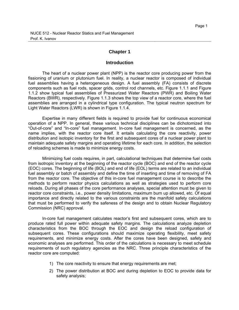
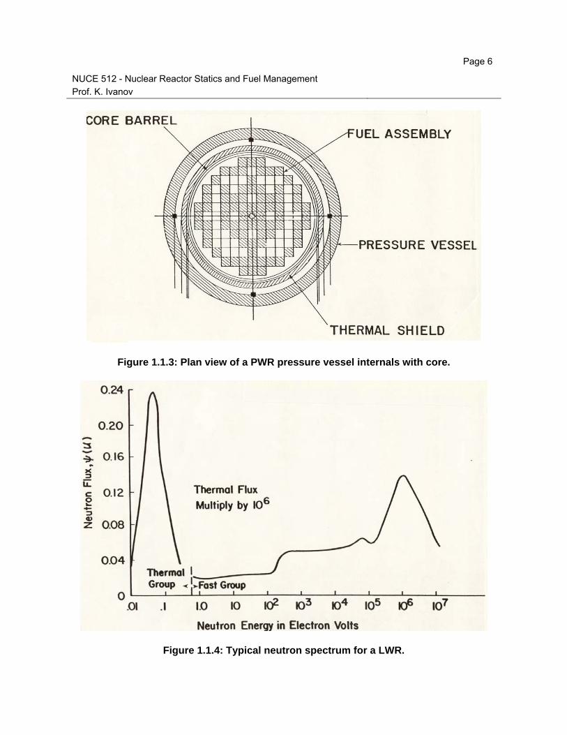
The heart of a nuclear power plant (NPP) is the reactor core producing power from the fissioning of uranium or plutonium fuel. In reality, a nuclear reactor is composed of individual fuel assemblies having a heterogeneous design. A fuel assembly (FA) consists of discrete components such as fuel rods, spacer grids, control rod channels, etc. Figure 1.1.1 and Figure 1.1.2 show typical fuel assemblies of Pressurized Water Reactors (PWR) and Boiling Water Reactors (BWR), respectively. Figure 1.1.3 shows the top view of a reactor core, where the fuel assemblies are arranged in a cylindrical type configuration. The typical neutron spectrum for Light Water Reactors (LWR) is shown in Figure 1.1.4.
Expertise in many different fields is required to provide fuel for continuous economical operation of a NPP. In general, these various technical disciplines can be dichotomized into “Out-of-core” and “In-core” fuel management. In-core fuel management is concerned, as the name implies, with the reactor core itself. It entails calculating the core reactivity, power distribution and isotopic inventory for the first and subsequent cores of a nuclear power plant to maintain adequate safety margins and operating lifetime for each core. In addition, the selection of reloading schemes is made to minimize energy costs.
Minimizing fuel costs requires, in part, calculational techniques that determine fuel costs from isotropic inventory at the beginning of the reactor cycle (BOC) and end of the reactor cycle (EOC) cores. The beginning of life (BOL) and end of life (EOL) terms are related to an individual fuel assembly or batch of assembly and define the time of inserting and time of removing of FA from the reactor core. The objective of this in-core fuel management course is to describe the methods to perform reactor physics calculations as well as strategies used to perform core reloads. During all phases of the core performance analyses, special attention must be given to reactor core constraints, i.e., power density limitations, maximum burn up allowed, etc. Of equal importance and directly related to the various constraints are the manifold safety calculations that must be performed to verify the safeness of the design and to obtain Nuclear Regulatory Commission (NRC) approval.
In-core fuel management calculates reactor’s first and subsequent cores, which are to produce rated full power within adequate safety margins. The calculations analyze depletion characteristics from the BOC through the EOC and design the reload configuration of subsequent cores. These configurations should maximize operating flexibility, meet safety requirements, and minimize energy costs. After the cores have been designed, safety and economic analyses are performed. This order of the calculations is necessary to meet schedule requirements of such regulatory agencies as the NRC. Three principle characteristics of the reactor core are computed:
1) The core reactivity to ensure that energy requirements are met;
2) The power distribution at BOC and during depletion to EOC to provide data for safety analysis;

Page 2
NUCE 512 - Nuclear Reactor Statics and Fuel Management Prof. K. Ivanov
3) The isotopic inventory at the end-of-cycle (EOC) to permit economic analysis;
4) Reload to minimize energy costs.
Other reactor physics parameters, such as control rod worth, effective delayed neutron fraction, and effective neutron lifetime are determined for safety analyses. These parameters may not change significantly after the first few cycles. Because the safety analyses normally continue to be valid for later cycles, constraints may be used instead.
The nature of in-core fuel management dictates several practical tasks. More than a year before fuel is used in the reactor; the utility’s nuclear engineers must determine the fixed energy requirements for the reload cycle. But predicting the energy requirements precisely so far in advance is difficult because many things can happen before the fuel is actually used. Common causes in the past were fuel failures requiring that substantial fresh fuel be loaded, plant equipment failure forcing premature prolonged outage and thus an incentive to reload early, changes to the utility’s system plan requiring that the plant operates longer by doing a coastdown. We define”coastdown” when at a normal EOC the reactor is continued to be operated at less than full power.
Once the energy requirements are established for the next cycle, other factors must be designed: the enrichment of the fresh fuel, the reload configuration, poison control during depletion, fraction of depleted fuel to be removed, and the use of previously used fuel. These decisions must be made following a strict schedule. The fuel must be manufactured on time. Numerous safety analyses must be completed on schedule for the first few cycles and must be submitted to the NRC for its approval. In general, all subsequent reloads are designed to have safety characteristics similar to previous cycles and thus to fall within approved technical specifications. In this case, no new safety analysis need be performed. To minimize delays caused by unexpected events, a contingency analysis should determine operational characteristics of the core. Covering energy use about the expected requirements – the energy window – this analysis allows last-minute adjustments. However, the best insurance against long delays in nuclear analysis is to employ nuclear engineers equipped with a complete set of in-core fuel management computer codes. The engineers should have experience analyzing the behavior of the power plant’s core cycles.
1.1 Nuclear Fuel Cycle
The nuclear fuel cycle includes all activities involved in obtaining and irradiating fuel in nuclear reactors, as well as spent fuel processing and disposing of the fission product wastes produced during irradiation of these reactors. The many activities involved in the fuel cycle may be divided into three categories. The first category involves activities that take place prior to fuel irradiation, when fuel radioactivity levels are relatively low. These activities include milling, conversion to uranium hexafluoride, enrichment in the fissile isotope 235U (in the case of all but natural uranium fueled reactors), and fabrication into fuel elements and assemblies. These activities are designed as head-end fuel management.

Page 3
NUCE 512 - Nuclear Reactor Statics and Fuel Management Prof. K. Ivanov
The second category of activities involves fuel cycle design and irradiation of the fuel
assemblies in the reactor. These activities include evaluation of reactivity and control requirements, programming of fuel assemblies in the reactor, power distribution analysis, and core capability evaluation. This category is primarily the responsibility of the nuclear engineer, and will be covered in depth in later chapters of the book. It will be referred to as in-core fuel management.
The final category of fuel management activities includes those activities that involve operations on the highly radioactive spent fuel storage and shipping, reprocessing of the spent fuel to remove fission products and separate transuranium elements, and waste disposal. It will be designed as tail-end fuel management.
There are several features of nuclear fuel that are considerably different from fossil fuel. A unit mass of fissile material fissioned yields nearly four million times as much energy as a unit mass of coal burned. Nuclear fuel is therefore quite valuable. A second feature of nuclear fuel and the nuclear fuel cycle is the presence of radioactivity. Although activity levels in the head end of the fuel cycle are relatively low, they are not insignificant, and care must be taken to prevent the release of radioactivity to the environment. Once any fissioning has taken place in the fuel, activity levels resulting from both fission products and neutron capture products are extremely high, and the release of even a small fraction of this activity to the environment would cause acceptable radioactivity levels to be exceeded.
Another feature of nuclear fuel that differentiates it from other energy sources is that the material produced for use in some types of reactors, and some of the by-products of the reactor operation, could be used to produce crude nuclear explosive. For this reason, access too many phases of the fuel cycle must be carefully controlled, and the probability of diversion of such material reduced to a very low value.
A final feature of nuclear fuel management, as opposed to the management of fossil fuel, is the long time required between mining the ore, irradiation of the fuel in the reactor, and removal of fission product wastes. This process requires a minimum of two years and could extend too many decades if spent fuel is stored for an indefinite period prior to separation of fuel material from fission products, if this separation is performed at all.
Although the nuclear engineer may not be directly involved with the technical details of these activities, he or she should be familiar with how the major fuel processing steps are affected when changes are made in fuel design or reactor operation, as well as how these interactions affect fuel cycle economics.
A cycle is a period of time in which certain events are repeated in the same order and at the same intervals. This is the case with nuclear fuel cycle. Not all fuel cycles are the same, however, and there are a number of different types of fuel cycles that are of interest to us. The differences arise both because of differences in resource availability as well as differences in the state of technology or national policy objectives in various parts of the world.

Page 4
NUCE 512 - Nuclear Reactor Statics and Fuel Management Prof. K. Ivanov
There is large number of variations of nuclear fuel cycles. However, in practice, there are
only a handful of different cycles that best fit the needs of the particular enterprises and governments involved. For example, the United States has developed reactors that use enriched uranium, because the enrichment plants were available after World War II as a result of the Manhattan project. Also, the U.S. nuclear industry uses light water as coolant since this technology was originally developed for nuclear-powered submarines. Canada, on the other hand, chose CANDU reactor that does not require enrichment of the natural uranium. As a result, the Canadian nuclear industry is self-sufficient without going through the considerable expense of developing enrichment facilities. The use of natural uranium as fuel made possible by the well-developed heavy water (D2O) technology. The rest of this section gives a brief description of the major fuel cycles.
Figure 1.1.1: Cutaway of typical rod cluster control assembly for a PWR.

Page 5
NUCE 512 - Nuclear Reactor Statics and Fuel Management Prof. K. Ivanov
Figure 1.1.2: Fuel assembly for a BWR.
Page 6
NUCE 512 - Nuclear Reactor Statics and Fuel Management Prof. K. Ivanov
Figure 1.1.3: Plan view of a PWR pressure vessel internals with core.
Figure 1.1.4: Typical neutron spectrum for a LWR.

Page 7
NUCE 512 - Nuclear Reactor Statics and Fuel Management Prof. K. Ivanov
Once-Through Cycle: this cycle is shown in Figure 1.1.5 and represents the LWR fuel
activities as practiced by the U.S. nuclear industry at the end of last century. Looking at Figure 1.1.5, one notices that the once-through cycle is not a whole cycle but stops at the spent fuel stage. The spent fuel is considered a waste product that will be disposed of as prescript by the Nuclear Wasdte Policy Act (NWPA).
Uranium and Plutonium recycled in LWRs: In this case the spent fuel is reprocessed and the U and Pu are recovered. The reprocessed U is stored. The Pu, in the form of PuO2, is mixed with depleted uranium, in the form of UO2, and fabricated into fuel known as MOX (Mixed Oxide). The MOX fuel is placed in the core of an LWR where it fissions and produces power. With the signing of nuclear weapon reduction treaties and the dismantling of a large number of such weapons, a considerable amount of so-called weapon-grade U and Pu will become available and may be used as a fuel in LWRs. The main advantage of recycling U and Pu are a decrease in the needed U ore and also a reduction in enrichment services. The U.S. government is recycling reactor-grade uranium for the needs of its nuclear-powered vessels. The civilian U.S. nuclear industry does not find it economical to reprocess its spent fuel and use the recovered Pu as MOX fuel. Other countries, however, are practicing reprocessing and recycling of reactor-grade Pu, e.g. France.
Breeder reactor fuel cycle: This cycle is, essentially, the one shown in Figure 1.1.6. In a breeder reactor cycle reprocessing is necessary; no reactor can be a breeder without the fuel being reprocessed and recycled. Thus, a breeder reactor must utilize a closed flue cycle. When a breeder reactor starts operating, it requires initial fuel to operate that may be 235U or Pu and 238U. Or, in principle, it may start operating with 233U and 232Th. After a few cycles, the true breeder produces enough new fuel (Pu or 233U) to be self –sufficient. It is interesting to note that whereas a breeder using Pu as a fuel operates as fast neutron reactor, a breeder using the Th-233U cycle may operate as a thermal reactor.

Page 8
NUCE 512 - Nuclear Reactor Statics and Fuel Management Prof. K. Ivanov
Figure 1.1.5: The once-through cycle nuclear fuel activities.
Figure 1.1.6: The nuclear fuel activities taking reprocessing of uranium and plutonium into account.

Page 9
NUCE 512 - Nuclear Reactor Statics and Fuel Management Prof. K. Ivanov
1.2 In-core Fuel Management
The term “fuel management” is not uniquely defined. It means different things to different people. There are, however, several activities that definitely belong to this area, as given in the following partial list:
a) Supply of materials and services required in the various steps of the nuclear fuel cycle (examples: uranium, conversion services, enrichment, services, fabrication, transportation, of fresh fuel, disposal of spent fuel, and storage);
b) Developmental, reviews, and evaluation of bids related to contracts that supply materials and services;
c) Study of the cost of fuel as one of the cost components for the generation of electricity;
d) Study of requirements and design of the fuel needed for successive fuel cycles;
e) Operational considerations related to fuel performance in the core;
f) Power history of the reactor, i.e. operational history of the fuel in the core;
g) Core loading pattern;
h) Refueling activities;
i) Storage and disposal of spent fuel.
From this list, items a), b), c), and i) constitute “out-of-core” fuel management activities. The rest of the activities belong to “in-core” fuel management and are the subject of this course.
The main objective of the fuel manager is to minimize fuel costs, thus reducing the cost of generating electricity. The person responsible for this task tries to achieve this objective by altering the parameters that can be changed without violating any of the constraints imposed by operational and safety considerations. Operational constraints include:
i. Refueling must be scheduled for a period of low demand;
ii. The reactivity of the fuel must be adequate to achieve the scheduled burnup;
iii. The core should have adequate reactivity control;
iv. Reduction of the fast neutron flux at the pressure vessel (of PWRs.)
The safety constraints are expressed in terms of the values of certain parameters that are not allowed to exceed certain predetermined limits. Examples are:
i. The peak-to-average power ratio;
ii. The maximum temperature in the core;
iii. The deviation from nuclear boiling ratio (DNBR);
iv. The core reactivity;

Page 10
NUCE 512 - Nuclear Reactor Statics and Fuel Management Prof. K. Ivanov
v. The temperature coefficient of reactivity.
The fuel loading and the power distribution in the core must be such that none of the safety parameters exceeds the prescribed values. The objective of minimizing fuel costs sounds simple enough, but the factors that determine the “cost” may change over the years. The “cost” may not be strictly and directly financial. To make this point better understood, a brief history of fuel management objectives and concerns for the U.S. nuclear power industry are discussed here.
Civilian nuclear started in the United States in the late 1950s under the premise of a positive value for the spent fuel. The U.S. government had promised the utilities that it would buy from them the plutonium generated in their reactor for use in breeders; thus, the fuel managers carried on in their books a future income to be collected from spent fuel. There was also an inherent promise by the government to take the spent fuel away from the utilities no later than two years after discharge from the core. Based on this understanding, the early plants provided for about five years of spent fuel storage on site. At that time, the optimization studies of nuclear fuel management were based on the assumption that uranium prices would be stable and low and that reprocessing of the spent fuel would also occur at relatively low prices. No particular attention was paid to final burnup.
By about 1970, the U.S. government seemed committed to the reprocessing and recycling of the spent fuel. The development of a Generic Environmental Impact Statement for Mixed-Oxide Fuel (GESMO) was set in motion, to be completed by 1976. In 1977 GESMO was almost completed. With Nuclear Fuel Services Company in New York State (NFS), the first private reprocessing plant in the United States, in operation from 1966 to 1972, and another commercial reprocessing plant at Barnwell, South Carolina, almost ready for operation, the new U.S. administration decided not to allow reprocessing in the United States. The newly created U.S. Department of Energy (DOE) was then instructed to initiate a study of new nuclear fuel designs that would achieve burnups of the order of 45,000 to 50,000 MWD/MTU (and today it is moving toward 75,000 MWD/MTU). This value is higher than the typical burnup of 28,000 to 30,000 MWD/MTU achieved by LWR fuel up to that time. The new high-burnup fuel would presumably constitute an alternative to reprocessing and recycling for better utilization of uranium resources. The advantage is obvious, at least as far as the quantity of needed uranium is concerned, since the reciprocal of burnup gives MTU/MWD, i.e., mass of fuel per unit energy produced. It was estimated that increasing the burnup from 33,000 to 50,000 MWD/MTU in PWRs would reduce the mass of yellow cake required (U3O8) by ~15%, the number of separative work units (SWUs) by 1 to 3%, and the number of discharged assemblies by ~40%, annually. By 1988, considerable experience with the new fuel design for LWRs had been accumulated.
An even better utilization of nuclear fuels could be achieved if plutonium recycling were to be implemented. Of course, plutonium generated in LWRs in the course of their normal operation is partially burned in those same reactors, and contributes up to 20% of the plant power in same cases.

Page 11
NUCE 512 - Nuclear Reactor Statics and Fuel Management Prof. K. Ivanov
By 1977 many utilities were hard pressed in order to find space for storage of their spent
fuel. The new high-burnup fuel design would certainly help, but its implementation was years away. Because immediate relief for spent fuel storage was necessary at certain plants, studies were undertaken by many utilities to determine how to alleviate this problem. Two ideas were considered, and in many plants both were implemented. One was redesigning the existing fuel storage racks in spent fuel pools to provide space for more fuel assemblies. The other was an extension of each cycle from 12 to 18 months. Such an extension resulted in fewer fuel assemblies being used over the life of the plant and at the same time reduced fuel cycle cost, primarily because of the decrease in the average (over plant lifetime) downtime required for refueling. However, the higher burnup requires more highly enriched fuel, which necessitates that fuel storage racks be designed to hold more highly enriched fuel without a criticality accident.
In 1982, Congress passed the NWPA, amended in 1987. In accordance with the NWPA, the federal government, through DOE, is obligated to take the spent fuel away from the plant, for a fee, and dispose of it properly. More than that, if a utility needs storage space before the government is ready to take the fuel, the NWPA obligates the government to provide interim storage. Thus, storage of spent fuel appeared to exist as an issue that affected the fuel cycle.
The NWPA obligated the utilities that own and operate nuclear power plants to pay the government, starting in April 1983, a fee of $ 0.001/kWh (e) of nuclear generated electricity. The money accumulated in this fashion will be used for research and development and all other costs associated with the disposal of the spent fuel. Thus, an expense was officially established for the disposal of spent fuel instead of an income from the sale of plutonium produced in the course of a plant’s operation.
As the cost of constructing nuclear power plant increased, and operating experiences accumulated, many people in the nuclear industry started to discuss the possibility of extending the life of a plant beyond its original 30-yr license. Any extension would require certification by the U.S. Nuclear Regulatory Commission (NRC) that all safety-related components are sound and will operate properly under normal and abnormal conditions.
The primary safety component is the pressure vessel. As a result of neutron bombardment, the steel of a pressure vessel suffers radiation damage (damage directly related to the magnitude of the neutron fluence). Extension of plant life would require less radiation damage to the pressure vessel, which means, in turn, fewer neutrons bombarding it. How to achieve this objective, namely, the reduction of the number of neutron leaking out of the core and bombarding the pressure vessel, became the latest objective, or constraint, of nuclear fuel management. This issue is known as “low-leakage core management”.
1.3 Refueling Activities
Refueling of nuclear reactor plants is generally guided by two major requirements: it should take place during the proper refueling “window” and it should be completed as quickly as
Page 12
NUCE 512 - Nuclear Reactor Statics and Fuel Management Prof. K. Ivanov
possible. Since a NPP also needs maintenance that can be best performed when the plant is shut down, the refueling activities are not only those strictly related to the discharge of the spent fuel and the insertion of the new fuel, but also the necessary maintenance tasks.
The refueling “window” mentioned above is a time of low demand when the NPP can be shut down without putting undue pressure on the reserve of the utility. All utilities that own NPPs operate them as base load plants, i.e., they operate them at the maximum possible power all the time. For load following, a utility utilizes smaller fossil plants. The reason for this mode of operation is the large size of the NPPs and their relatively low cost to operate. Every nuclear utility would like to shut down a NPP at a time when there are adequate reserves and there is not need to buy replacements power. The period of low demand, the refueling window, is not the same for all the utilities. It depends on the country, and on the region of the country that the company serves and on what fraction of its total capacity the NPP represents.
Utilities in the Midwest of U.S., for example, face two peak load demands, one in the summer and one in the winter. There are two refueling windows. The first is about from March to May, and the second is about from September to October. Keeping in mind that refueling takes about five weeks, it is obvious that these periods do not coincide with either the hot summer or the cold winter days. For utilities serving the southern regions of U.S., there is only one peak demand, during the summer, and the refueling window is therefore about from October to April.
If the reactor can be refueled on-line, i.e., without having to shut down, there is considerable flexibility in the refueling planning. Examples of reactors for which on-line refueling is possible are the CANDU, a heavy-water-moderated, natural-uranium-fueled reactor developed by Canada; the pebble bed, a gas-cooled reactor designed in Germany; and the Russian RBMK (Chernobyl-type) reactor.
1.3.1 Planning for a Refueling Outage
Planning for the outage is extremely important. Just how important becomes obvious if one remembers that the 24-hour income from a 1200-MW(e) plant is between $800,000 and $1,000,000. Thus, even hours count since the loss of income per hour is from $33,000 to $42,000. The loss of income is particularly painful if the utility has to buy replacement power from another company. For a successful outage, the utility ought to:
i. Establish an outage organization with a single person in charge at least six months before shutdown;
ii. Maintain, at all times, an inventory of outstanding tasks to be performed;
iii. Prepare as soon as possible the master list of tasks that have to be done during the next refueling.
Every item in the list is examined for:

Page 13
NUCE 512 - Nuclear Reactor Statics and Fuel Management Prof. K. Ivanov
i. The possibility of deferral
ii. Relative priority;
iii. The number of other tasks affected by it;
iv. The need for off-site expertise and equipment;
v. The need for contingency preplanning, particularly for critical items.
Of the items in the master list, the most important ones are those that affect what is called the “critical path”. The critical path is the path that will take the plant from shut down to startup in the minimum time, resulting in the shortest outage. Critical tasks are those that may lengthen the critical path. Many methods have been developed for the determination of the critical path. One of them, described briefly here, is the critical path method (CPM); another, also used frequently, is called the program evaluation and review technique (PERT).
Consider planning for the refueling of a reactor. All the activities that have to be performed are identified by a letter or a number (see Figure 1.3.1). For example, number 10 may indicate reactor vessel head removal, number 20 may mean opening a steam generator, number 30 may be fuel removal, number 80 may be reintroducing fuel back into the core, etc. The number above each circle in Figure 1.3.1indicates the time it takes, in weeks, to complete the corresponding activity. The arrows indicate the sequence in which each operation must be performed. For example, the reactor vessel head must be removed prior to fuel removal. Having two or more arrows originating from one activity means that those tasks may be performed in parallel. For example, activities 20 and 30 may both start after 10 are completed. As shown in the figure, there are several options or paths that may lead to the final activity shown (100). From Figure 1.3.1 it can be seen that path B is the critical path because any slippage in any of the activities encountered along this path, will cause a delay in reaching activity 100. Path B may be the longest in terms of actual time span, but it represents the minimum time waiting between any two activities.
Figure 1.3.1: A typical CPM diagram.

Page 14
NUCE 512 - Nuclear Reactor Statics and Fuel Management Prof. K. Ivanov
1.3.2 New Fuel Procurement
The activities necessary to design, fabricate, and have the fuel transported on-site start about two years before the plant is shut down for refueling. The detailed list of activities is presented in Table 1.3.1, in chronological order, assuming refueling begins on 2/1/2000, as an example. This is also shown in Figure 1.3.2.
Some utilities have in-house capability to perform all the tasks necessary for the design and safety analysis of the new fuel; others prefer to hire outside persons or organizations to do the work for them. Because a utility may realize several and considerable benefits by performing all the work in-house, the Electric Power research Institute (EPRI) has developed a methodology for the complete analysis required for the new fuel. This work by EPRI is known as the Reactor Analysis Support Package (RASP).
1.3.3 New Fuel Design Activities
The major requirements for the new fuel are (a) to satisfy the energy requirements of the cycle and (b) to operate within the technical specifications of the plant. The new fuel design activities have as a goal the determination of the enrichment and number of assemblies for the new batch, the actual mechanical design of the new assemblies and the core loading pattern. This proceeds along the following steps.
1. Determine cycle operational and safety requirements;
2. Develop a preliminary core design that includes number of assemblies, old and fresh; enrichment; and loading pattern;
3. Identify the values of the key safety parameters used in the Final Safety Analysis Report (FSAR);
4. Determine the values of the key safety parameters for the new cycle;
5. Confirm the applicability of FSAR accident analysis. If applicability is not possible because of changes in the new fuel, the issue should be re-examined;
6. Identify technical specification changes required;
7. Finalize core design;
8. Write reload safety document.
1.3.4 Licensing the New Fuel
The licensing requirements for new fuel are described in the Code of Federal Regulations, specifically in 10CFR50. Detailed guidance for the content of applications for

Page 15
NUCE 512 - Nuclear Reactor Statics and Fuel Management Prof. K. Ivanov
license and safety analysis reports is given in a regulatory guide entitled “LWR Core Reloads: Guidance on Applications for Amendments to operating Licenses on Refueling and Startup Tests”. The regulatory guide identifies three cases
a. “No change in facility or procedures, as described in the safety analysis report”;
b. “Changes in facility or procedures that do not involve an unreviewed safety question or a change in the technical specifications”;
c. “Changes in facility or procedures that do involve an unreviewed safety question or a change in some provision of the technical specifications”.
If the refueling falls under cases (a) or (b) above, the activity may be carried out without specific authorization by the NRC. Information about the refueling is included in the annual report that the utility is required to submit to the NRC. This report contains a brief description of changes, tests, and experiments and a safety evaluation of each one.
If the refueling falls under case (c), an amendment to the operating license of the facility is required. The utility must submit an application and a safety analysis report. The general objective of the safety report is to show the NRC that the new core is, at a minimum, equally acceptable from the safety point of view as the one it replaced.
Table 1.3.1: A list of refueling activities.

Page 16
NUCE 512 - Nuclear Reactor Statics and Fuel Management Prof. K. Ivanov
Figure 1.3.2: The new fuel procurement activities calendar.
1.3.5 Refueling Sequence Tasks
There are no two refueling sequences that are identical in any one plant or in different plants because maintenance activities are an essential part of the tasks performed during shutdown for refueling, and it is highly unlikely that maintenance activities will be identical for two different shutdowns. However, the actual refueling activities follow a certain pattern and they take a certain time to perform. There is enough experience at this time, for both BWRs and PWRs, to make possible the enumeration of the major activities and their approximate duration. The reader should keep in mind that activities may overlap.
One may divide the tasks into six categories, in terms of the time period in which they are performed:
1. Shutdown activities prior to reloading operations: examples of activities during this period are cooldown, de-inserting, drywell and vessel disassembly, etc., for BWR; containment service, preparing crane, cleaning the refueling pool, preparing transfer canal, removing reactor vessel head insulation, etc., for PWRs.
2. Unloading the fuel: in LWRs, although only a fraction of the core is discharged at every refueling, the whole core is unloaded because (A) all the assemblies are inspected for leaks, (b) work needs to be performed inside the pressure vessel (inspection, repair, replacement of internals), and (c) the safety requirements are quite different depending on whether or not fuel is

Page 17
NUCE 512 - Nuclear Reactor Statics and Fuel Management Prof. K. Ivanov
present inside the vessel. The average time it takes to remove one assembly from the core to the spent fuel is about 1/3 h.
3. Fuel inspection (sipping): all assemblies that will go back into the core must be inspected for leaks, i.e. the fuel must undergo sipping. The time it takes for sipping depends on the method and on the number of assemblies that failed. Sipping may be done concurrently with unloading the fuel.
4. Work on in-vessel (internals) and ex-vessel equipment: these activities vary considerably from refueling to refueling and from plant to plant and cycle to cycle.
5. Reloading the fuel and closing the vessel: same as in item 2 above, minus the time for inspection.
6. Equipment inspections and repair before startup tests: examples are reactor coolant pump work, main turbine work, steam generator maintenance, reconnection of instrumentation, etc. These activities fall under maintenance but they are listed here because they are performed, to some extent, during every refueling
7. Startup tests: these are tests required before the reactor reaches 100% of its design power. Examples are reactor coolant heatup, reactor criticality, turbine generator on-line, and various tests to verify nuclear and thermal-hydraulic parameters at various power levels.
The downtime for refueling LWRs in the United States has decreased continuously. The average time for refueling has gone down from 83 days in 1989 to about 40 in 1999, with some plants completing refueling in less than 30 days. This considerable improvement in performance, translating in better capacity factors and therefore reduced generating costs, is due, primarily, to the establishment of a better management team responsible for the refueling outage.
As afore mentioned, in addition to the refueling itself, the outage is used to complete other tasks generally referred to as maintenance tasks. Maintenance has to do with the following activities being applied to components of equipment or whole pieces of equipment: modification, repair, inspection and testing, replacement, and cleaning.
1.3.6 Radiation Exposure during Refueling
Refueling activities are the major source of radiation exposure to personnel at nuclear power plants. Although the annual limit of exposure for radiation workers is 50 mSv (5 rem), the operators of nuclear power plants are required to follow the “as low as reasonably achievable” (ALARA) principle, as a result of which the average exposure to personnel over a year continuously declined from about 7 man-Sv (700 man-rem) for PWRs and 10 man-Sv (1000 man-rem) for BWRs in 1981 to about 3 man-Sv for PWRs and 4 man-sv in BWR in 1990. There is a continuous effort in nuclear power plants all over the world to follow such practices so that

Page 18
NUCE 512 - Nuclear Reactor Statics and Fuel Management Prof. K. Ivanov
the average exposure to workers will be minimized. For LWRs, experience has shown that proper control of the water coolant chemistry may reduce the radiation dose considerably.
In LWRs, most of radiation dose is a result of radioactive materials that are removed by the chemical action of the water flowing through the core and from the assemblies and the other internals of the pressure vessel. These material, generally referred to as “crud”, have been activated by neutrons in the core and, once entered into the coolant, they circulate with it. In PWRs, the crud is retained in the primary loop unless there is a leak in one of the steam generator tubes. In BWRs, the crud will reach the turbine. Two cobalt isotopes are the primary source of radiation; they are 60Co, produced by the (n,γ) reaction with 59Co and 58Co produced by the (n,p) reaction with 58Ni.
In PWRs, experience has shown that there is a considerable reduction in the radiation field if the pH of the water in the primary loop is kept at 6.9 or higher and the lithium concentration is between 2 to 7 ppm.
In BWRs, there is no unanimity about the best method for water chemistry control. General electric uses injection of zinc oxide into the fed water in the range of 5 to 15 ppb. The Japanese adopted this method to control the Ni/Fe ratio to 0.2 ppb, either by bypassing the condensate system or by iron injection.
1.4 Glossary of Nuclear Fuel Terms
In this section we will define some of the terms most frequently used in fuel management and fuel cycle analysis.
Batch – A group of assemblies entering and leaving the reactor core at the same time. This will be a minimum of one assembly per batch. The batch is composed of the same fuel type and enrichment.
Book life – The time that a utility must keep track of a “batch” of fuel from the purchase of the uranium through fuel fabrication, burnup, and cooling. When the U.S. Department of Energy (DOE) takes ownership of the fuel “batch” from the utility, the utility removes the fuel batch from its books.
Burnup – The energy produced by the fuel expressed in megawatt days per metric ton of uranium (MWD/MTU). MWD/MTU corresponds to the fission of 1.3 g of fissile material, including the production of 236U by non-fission capture.
Capacity Factor (CF) – CF= (energy produced during time T)/(P0*T); where P0 is the design power.

Page 19
NUCE 512 - Nuclear Reactor Statics and Fuel Management Prof. K. Ivanov
Cycle Operating Length – The time period between the reactor refueling. It is equal to
“fuel residence time” if all fuel is replaced at each refueling. If 1/n of the core is replaced at one time, then
Fuel residence time = n x cycle operating length
Enrichment – This term is used to describe the percentage of a specified isotope present in a mixture of isotopes of the same element. Both weight and atom percent are used. It is occasionally (but incorrectly) used to describe the ratio of fissile to total fuel material (e.g., percent of plutonium in a mixture of plutonium plus uranium).
Fertile – Isotopes that can be converted to fissile material by the capture of a neutron; e.g., 238U and 232Th.
Fissile – Isotopes that will fission with slow (thermal) neutrons; e.g., 235U, 233U, 239Pu, and 241Pu.
Fuel Loading (M) – The fuel loading of a reactor is most commonly defined as the total weight of fissionable (fissile plus fertile) material in the reactor. In some cases such as with metallic alloy fuel or breeder reactor fuel, the loading may be defined as the weight of fissile material only. Units are kg or metric tons.
Fuel Inventory (I) – This term describes the total fuel weight in the fuel cycle, and has the same units as fuel loading. It is usually 30 to 100 percent greater than fuel loading.
Fuel Residence Time – The calendar time between insertion of a given batch of fuel and removal of that batch from the reactor. Note that
Fuel residence time = (Burnup)/(CF*Ps) days
Linear Power Density – Power generation per unit length of fuel element. It is most commonly used when the fuel elements are cylindrical rods. Units are W/cm.
Net Plant Efficiency (η) – The ratio of net electrical power output to the total thermal power produced by the fuel.
On the Books – A traditional accounting term meaning an investment is recorded on the utility ledger. Usually all tax information is included.
Power density – Power generation per unit of volume of reactor core. This is also sometimes used to express power per unit volume of fuel material. Units are kW/l.
Reprocessing – The chemical processes of recovering plutonium, 233U, and unused uranium from spent or irradiated fuel.

Page 20
NUCE 512 - Nuclear Reactor Statics and Fuel Management Prof. K. Ivanov
Separatuive Work Unit (SWU) – A unit of measure indicating the physical effort needed for a certain degree of enrichment; cost of enrichment is proportional to the physical effort.
Sipping – The process of examining the fuel assemblies for failed fuel rods.
Specific Power (Ps) – The thermal power produced per unit of fuel loading. Units are kW/kg of fuel material.