Chapter 01 Introduction · 2019-08-21 · 22/08/62 3 Chapter 1 Introduction Contents Drawing...
15
22/08/62 1
Transcript of Chapter 01 Introduction · 2019-08-21 · 22/08/62 3 Chapter 1 Introduction Contents Drawing...
22/08/62
1

22/08/62
2
พรีเรคคูสิท
22/08/62
3
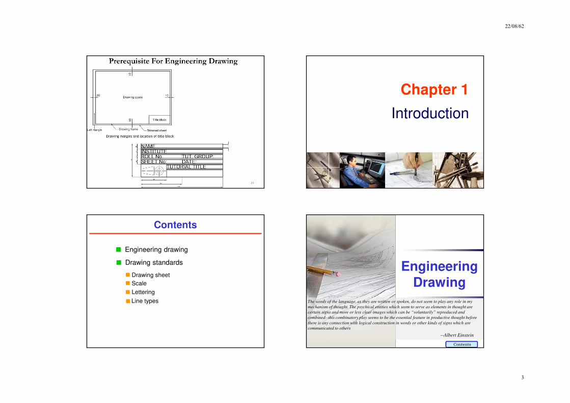
Chapter 1
Introduction
Contents
Drawing standards
Engineering drawing
Drawing sheet
Scale
Lettering
Line types
Engineering
Drawing
The words of the language, as they are written or spoken, do not seem to play any role in my
mechanism of thought. The psychical entities which seem to serve as elements in thought are
certain signs and more or less clear images which can be “voluntarily” reproduced and
combined--this combinatory play seems to be the essential feature in productive thought before
there is any connection with logical construction in words or other kinds of signs which are
communicated to others
--Albert Einstein
Contents

22/08/62
4
1. Try to write a description of
this object.
2. Test your written description
by having someone attempt
to make a sketch or visualize
from your description.
Effectiveness of Graphic Language
The word language is inadequate for describing the size,
shape and features completely as well as concisely.
You can easily understand that …
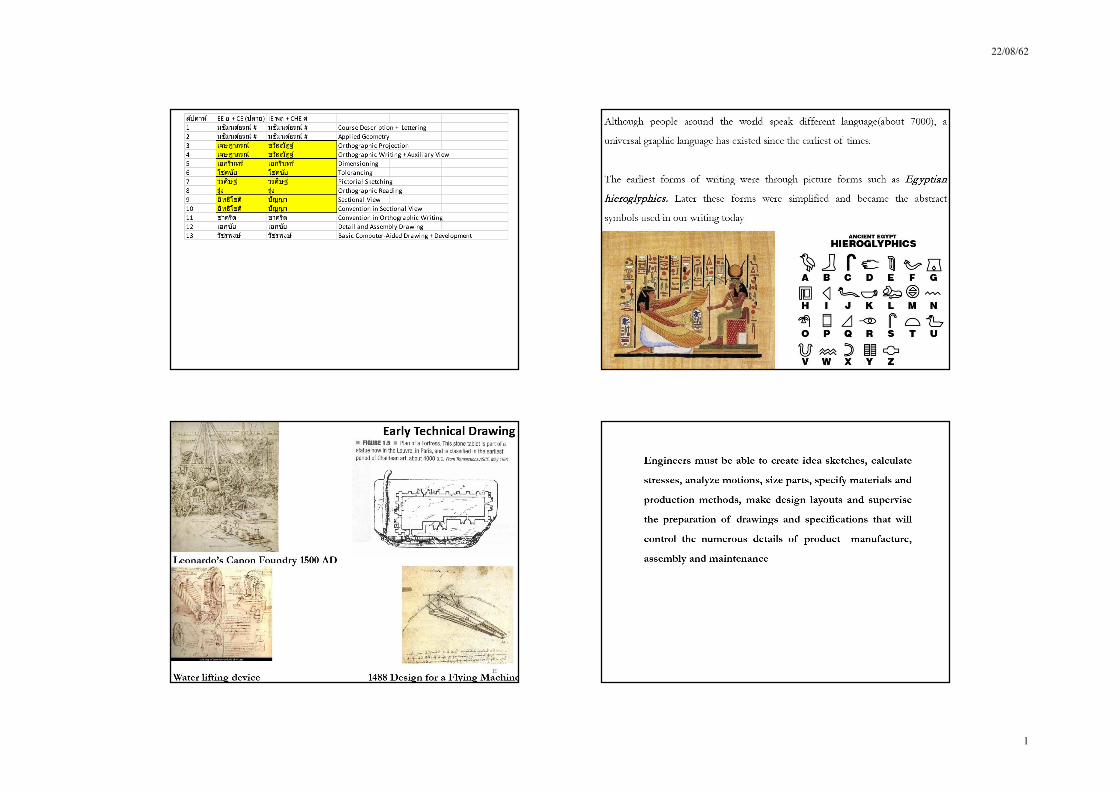
Graphic Language inEngineering Drawing
“Engineering drawing” or “blueprint” uses lines to
represent the features of an object.
Features of an object are surface (include plane) and
edge.
Surface
Edge
A drawing can be created in 3 ways
Ways to Create anEngineering Drawing
1. Freehand sketch
2. Using typical drawing instruments
3. Using a computer
Example
Create a Drawing : Freehand sketch
The lines are drawn using only pencil and erasers on a
blank or grid paper.
Pictorial sketch Orthographic sketch
22/08/62
5
Example
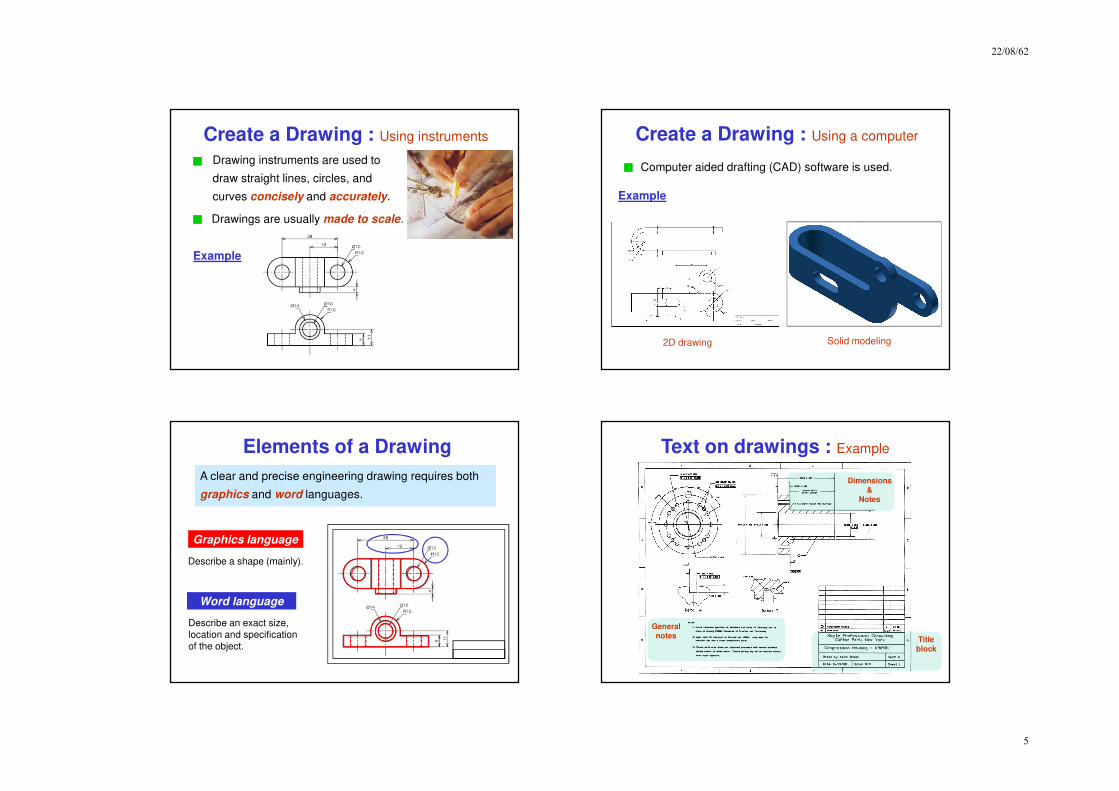
Create a Drawing : Using instruments
Drawing instruments are used to
draw straight lines, circles, and
curves concisely and accurately.
Drawings are usually made to scale.
Example
Create a Drawing : Using a computer
Computer aided drafting (CAD) software is used.
2D drawing Solid modeling
Elements of a Drawing
A clear and precise engineering drawing requires both
graphics and word languages.
Graphics language
Describe a shape (mainly).
Word language
Describe an exact size, location and specificationof the object.
Text on drawings : Example
General
notes Title
block
Dimensions
&Notes
22/08/62
6
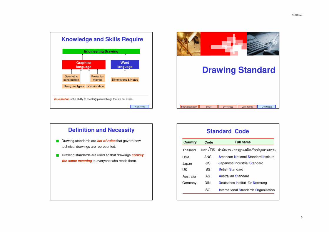
Knowledge and Skills Require
Graphics
language
Word
language
Dimensions & Notes
Visualization is the ability to mentally picture things that do not exists.
VisualizationUsing line types
Geometricconstruction
Projectionmethod
Engineering Drawing
Contents
Drawing Standard
Drawing sheet Scale Lettering Line types Contents
Definition and Necessity
Drawing standards are set of rules that govern how
technical drawings are represented.
Drawing standards are used so that drawings convey
the same meaning to everyone who reads them.
ISO International Standards Organization
Standard Code
ANSI American National Standard InstituteUSA
JIS Japanese Industrial StandardJapan
BS British StandardUK
AS Australian StandardAustralia
Deutsches Institut für NormungDINGermany
Country Code Full name
มอก./TIS สาํนักงานมาตรฐานผลิตภณัฑอ์ตุสาหกรรมThailand

22/08/62
7
Examples of TIS Standard
มอก. 210 2520 วิธ ีเขียนแบบทั %วไป : ทางเครื%องกล
มอก. 440 ล.1 2541 การเขียนแบบก่อสร้างเล่ม 1 ท ั %วไป
มอก. 446 ล.4 2532 ข้อแนะนําสาํหรบัการเขียนแผนภาพวงจรไฟฟ้า
มอก. 1473 2540 การเขียนแบบเทคนิค การติดต ั 6งสญัลกัษณ์สาํหรบัระบบท่อของเหลวระบบทาํความร้อน การระบายอากาศและระบบท่ออากาศ
Code number Contents
ที%มา : http://library.tisi.go.th/data/lib_resources/pdf/catalog-online49/tis/02_ICS.pdf
JIS Z 8311 Sizes and Format of Drawings
JIS Z 8312 Line Conventions
JIS Z 8313 Lettering
JIS Z 8314 Scales
JIS Z 8315 Projection methods
JIS Z 8316 Presentation of Views and Sections
JIS Z 8317 Dimensioning
Code number Contents
Examples of JIS Standard
Drawing StandardDrawing Sheet
Drawing standard Contents
Drawing Sheet : Standard size
Trimmed paper of
a size A0 ~ A4.
Standard sheet size
(JIS)
A4 210 x 297
A3 297 x 420
A2 420 x 594
A1 594 x 841
A0 841 x 1189
A4
A3
A2
A1
A0(Dimensions in millimeters)
22/08/62
8
Drawing space
Drawing
space
Title block
d
d
c
c
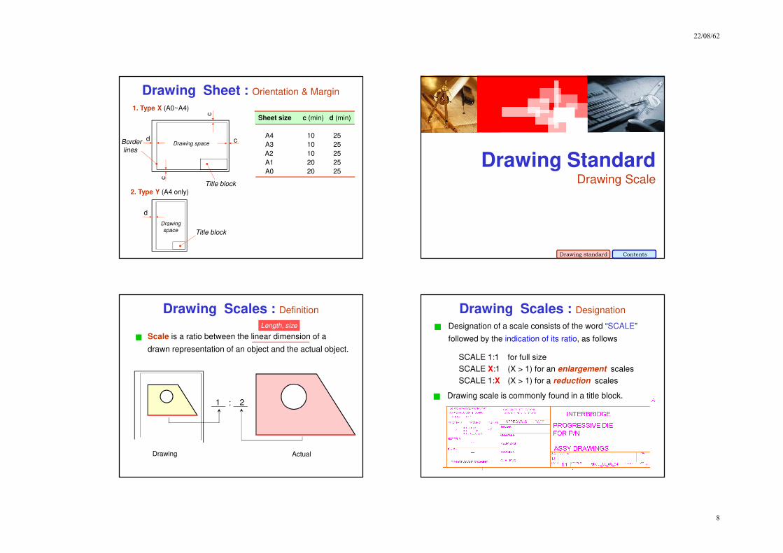
cBorder
lines
1. Type X (A0~A4)
2. Type Y (A4 only)
Title block
Sheet size c (min) d (min)
A4 10 25
A3 10 25
A2 10 25
A1 20 25
A0 20 25
Drawing Sheet : Orientation & Margin
Drawing StandardDrawing Scale
Drawing standard Contents
Drawing Scales : Definition
Drawing Actual
Length, size
:
Scale is a ratio between the linear dimension of a
drawn representation of an object and the actual object.
1 2
Designation of a scale consists of the word “SCALE”
followed by the indication of its ratio, as follows
SCALE 1:1 for full size
SCALE X:1 (X > 1) for an enlargement scales
SCALE 1:X (X > 1) for a reduction scales
Drawing Scales : Designation
Drawing scale is commonly found in a title block.
22/08/62
9
Dimension numbers shown in the drawing represent
the “true size” of an object and they are independent of
the drawing scale used.
Drawing Scales : Notes
Standard reducing scales are
1:2, 1:5, 1:10, 1:20, 1:50, 1:100
Drawing Scales : Standard scale
Standard enlarging scales are
2:1, 5:1, 10:1, 20:1, 50:1, 100:1
Drawing StandardLettering
Drawing standard Contents
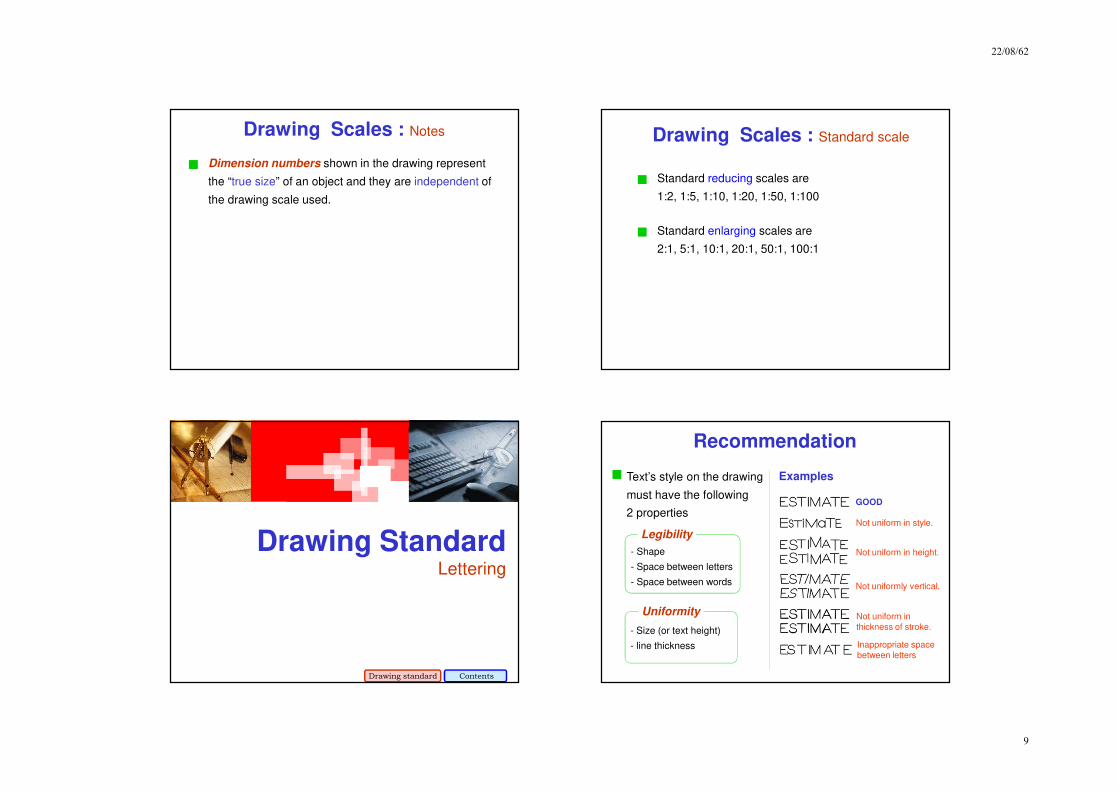
- Size (or text height)
- line thickness
- Shape
- Space between letters
- Space between words
Recommendation
Legibility
Uniformity
Text’s style on the drawing
must have the following
2 properties
Examples
GOOD
Not uniform in style.
Not uniform in height.
Not uniformly vertical.
Not uniform in
thickness of stroke.
Inappropriate space
between letters
22/08/62
10
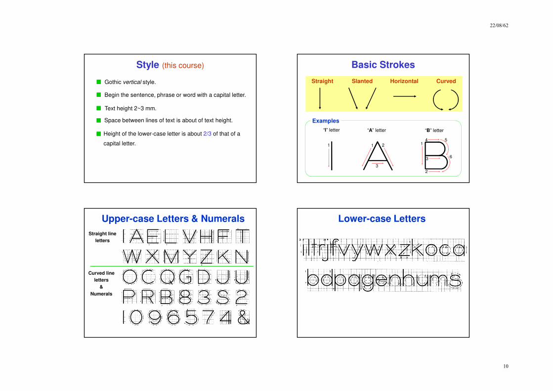
Style (this course)
Gothic vertical style.
Begin the sentence, phrase or word with a capital letter.
Text height 2~3 mm.
Space between lines of text is about of text height.
Height of the lower-case letter is about 2/3 of that of a
capital letter.
Basic Strokes
Straight Slanted CurvedHorizontal
1 1 2
3
“I” letter “A” letter
1
2
3
4 5
6
“B” letter
Examples
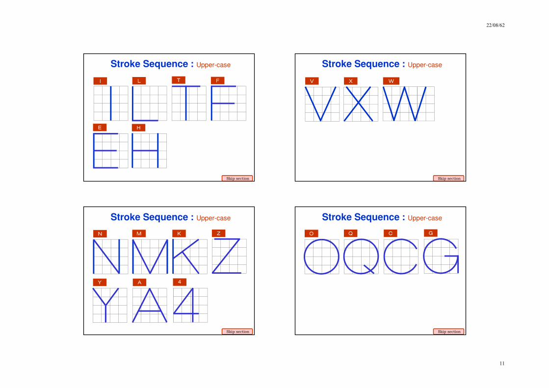
Suggested Strokes SequenceStraight line
letters
Curved line
letters
&
Numerals
Upper-case Letters & Numerals Lower-case Letters
22/08/62
11
I L T F
E H
Stroke Sequence : Upper-case
Skip section
V X W
Stroke Sequence : Upper-case
Skip section
N M K Z
Y A 4
Stroke Sequence : Upper-case
Skip section
O Q C G
Stroke Sequence : Upper-case
Skip section

22/08/62
12
D U P B
R J
Stroke Sequence : Upper-case
Skip section
5 7
Stroke Sequence : Upper-case
1 2
Skip section
6
8 9
0S 3
Stroke Sequence : Upper-case
Skip section
l i
Stroke Sequence : Lower-case
Skip section

22/08/62
13
v w x k
z
Stroke Sequence : Lower-case
Skip section
j y f
r
t
Stroke Sequence : Lower-case
Skip section
c o a b
d p q e
Stroke Sequence : Lower-case
Skip section
g n m h
u s
Stroke Sequence : Lower-case
Skip section
22/08/62
14
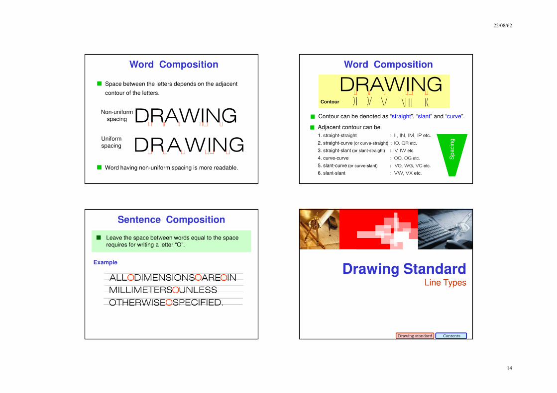
DRAWING
Word Composition
Non-uniform
spacing
Uniform
spacing DRAWING
Space between the letters depends on the adjacent
contour of the letters.
Word having non-uniform spacing is more readable.
Word Composition
Contour
DRAWING
Contour can be denoted as “straight”, “slant” and “curve”.
Adjacent contour can be
1. straight-straight : II, IN, IM, IP etc.
2. straight-curve (or curve-straight) : IO, QR etc.
3. straight-slant (or slant-straight) : IV, IW etc.
4. curve-curve : OO, OG etc.
5. slant-curve (or curve-slant) : VO, WG, VC etc.
6. slant-slant : VW, VX etc.
Sp
acin
g
Leave the space between words equal to the space
requires for writing a letter “O”.
Example
Sentence Composition
ALL DIMENSIONS ARE IN
MILLIMETERS
O O O
OUNLESS
OTHERWISE SPECIFIED.O
Drawing StandardLine Types
Drawing standard Contents
22/08/62
15
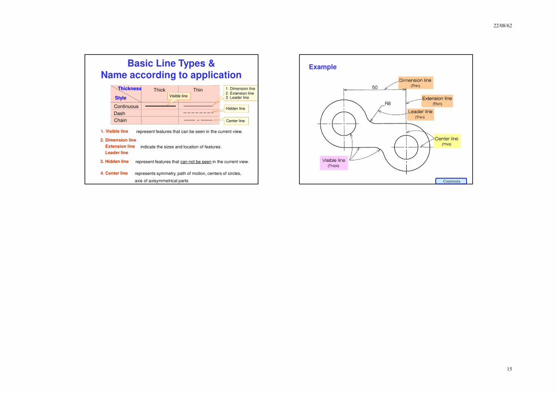
Basic Line Types &Name according to application
Continuous
Dash
Chain
Style
Thickness Thick Thin 1. Dimension line
2. Extension line3. Leader line
Center line
Hidden line
Visible line
represent features that can be seen in the current view.
represent features that can not be seen in the current view.
represents symmetry, path of motion, centers of circles,
axis of axisymmetrical parts
indicate the sizes and location of features.
1. Visible line
3. Hidden line
4. Center line
2. Dimension line
Extension line
Leader line
Example
Contents