Chap 3. Architectural Views - Electrical engineeringitraore/seng422-06/notes/arch06-3-2.pdf · Chap...
28
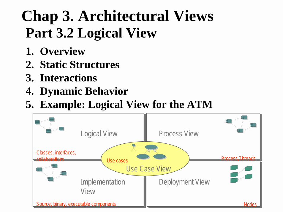
Chap 3. Architectural Views Logical View Process View Implementation View Process,Threads Classes, interfaces, collaborations Source, binary, executable components Deployment View Nodes Use Case View Use cases Part 3.2 Logical View 1. Overview 2. Static Structures 3. Interactions 4. Dynamic Behavior 5. Example: Logical View for the ATM
Transcript of Chap 3. Architectural Views - Electrical engineeringitraore/seng422-06/notes/arch06-3-2.pdf · Chap...
1
Chap 3. Architectural Views
Logical View Process View
Implementation View
Process,ThreadsClasses, interfaces,collaborations
Source, binary, executable components
Deployment View
Nodes
Use Case ViewUse cases
Part 3.2 Logical View1. Overview2. Static Structures3. Interactions4. Dynamic Behavior5. Example: Logical View for the ATM
2
1. Overview-The purpose of the logical view is to specify the functional requirements of the system. The main artifact of the logical viewis the design model:
÷The design model gives a concrete description of the functionalbehavior of the system. It is derived from the analysis model.
÷The analysis model gives an abstract description of the system behavior based on the use case model.
÷In general only the design model is maintained in the logical view,since the analysis model provides a rough sketch, which is later refined into design artifacts.
Design Model -The design model consists of collaborating classes, organizedinto subsystems or packages.
-Artifacts involved in the design model may include:÷class, interaction, and state diagrams ÷the subsystems and their interfaces described using package diagrams
3
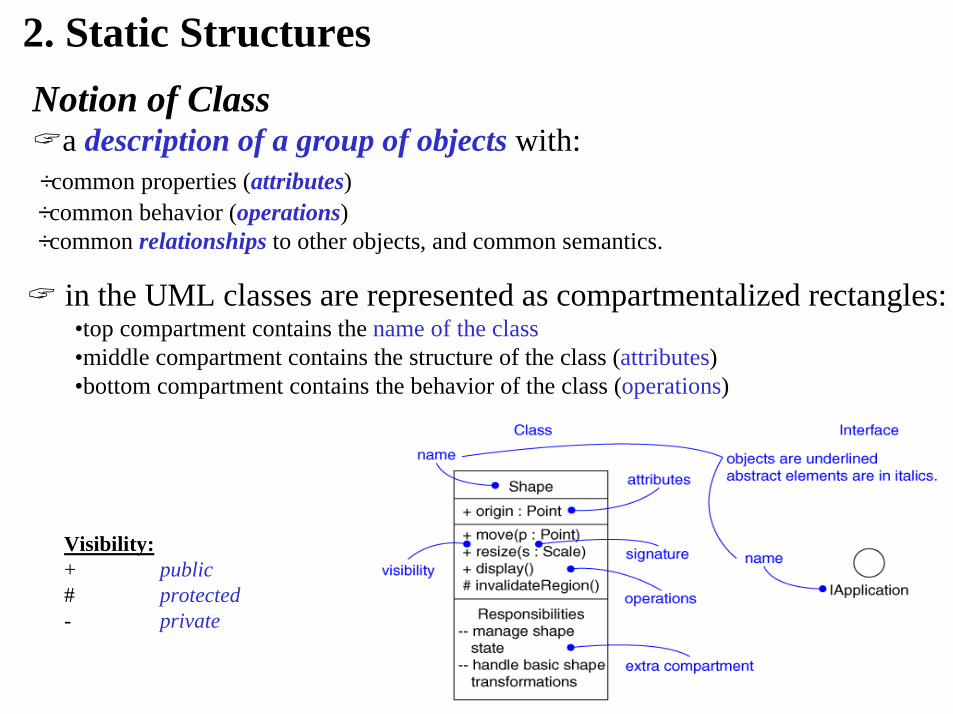
2. Static Structures
� in the UML classes are represented as compartmentalized rectangles:•top compartment contains the name of the class•middle compartment contains the structure of the class (attributes)•bottom compartment contains the behavior of the class (operations)
Visibility:+ public# protected- private
Notion of Class�a description of a group of objects with:÷common properties (attributes)÷common behavior (operations) ÷common relationships to other objects, and common semantics.
4
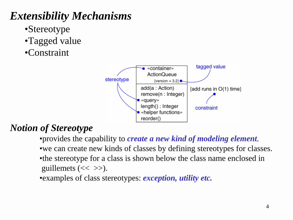
Extensibility Mechanisms•Stereotype•Tagged value•Constraint
Notion of Stereotype•provides the capability to create a new kind of modeling element.•we can create new kinds of classes by defining stereotypes for classes.•the stereotype for a class is shown below the class name enclosed in guillemets (<< >>).
•examples of class stereotypes: exception, utility etc.
5
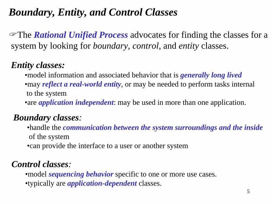
Boundary, Entity, and Control Classes
�The Rational Unified Process advocates for finding the classes for a system by looking for boundary, control, and entity classes.
Entity classes:•model information and associated behavior that is generally long lived •may reflect a real-world entity, or may be needed to perform tasks internal to the system
•are application independent: may be used in more than one application.
Boundary classes:•handle the communication between the system surroundings and the insideof the system
•can provide the interface to a user or another system
Control classes:•model sequencing behavior specific to one or more use cases.•typically are application-dependent classes.
6
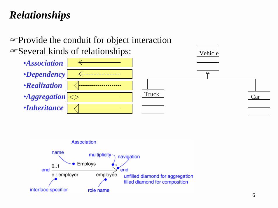
Relationships
�Provide the conduit for object interaction�Several kinds of relationships:
•Association•Dependency•Realization•Aggregation•Inheritance
Vehicle
Truck Car
7
** **
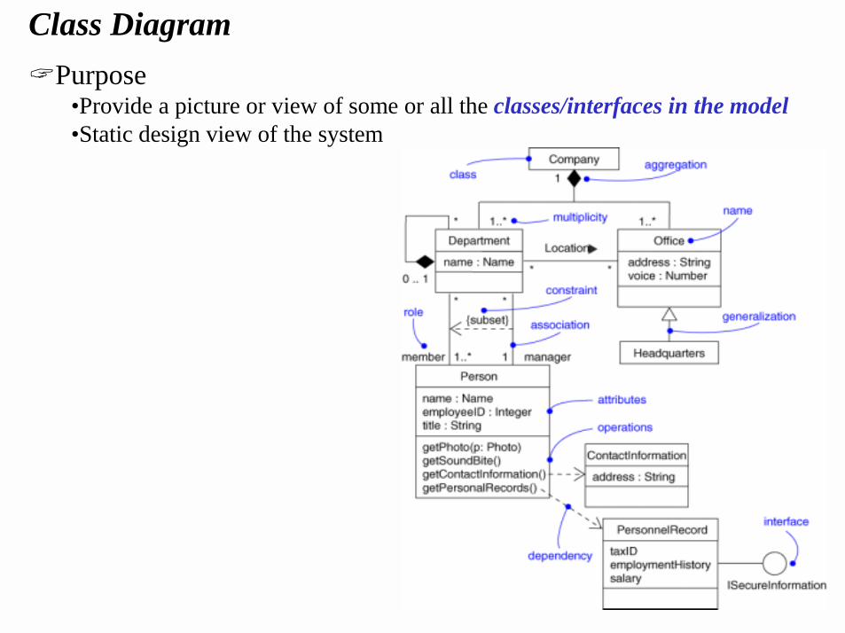
Class Diagram�Purpose
•Provide a picture or view of some or all the classes/interfaces in the model•Static design view of the system
8
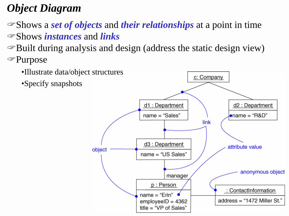
Object Diagram�Shows a set of objects and their relationships at a point in time�Shows instances and links�Built during analysis and design (address the static design view)�Purpose
•Illustrate data/object structures•Specify snapshots
9
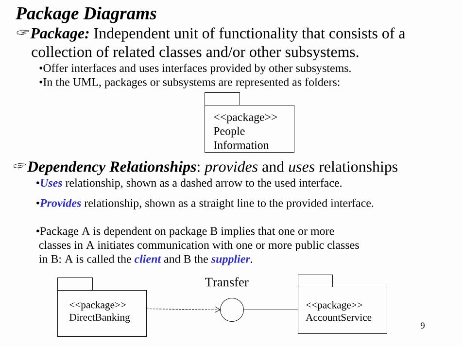
Package Diagrams�Package: Independent unit of functionality that consists of a
collection of related classes and/or other subsystems.•Offer interfaces and uses interfaces provided by other subsystems.•In the UML, packages or subsystems are represented as folders:
<<package>>PeopleInformation
�Dependency Relationships: provides and uses relationships•Uses relationship, shown as a dashed arrow to the used interface.
•Provides relationship, shown as a straight line to the provided interface.
•Package A is dependent on package B implies that one or moreclasses in A initiates communication with one or more public classesin B: A is called the client and B the supplier.
<<package>>DirectBanking
<<package>>AccountService
Transfer
10
3. Interactions
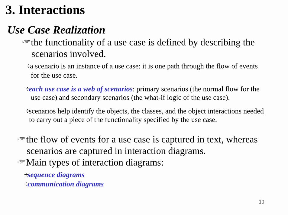
�the flow of events for a use case is captured in text, whereas scenarios are captured in interaction diagrams.
�Main types of interaction diagrams: ÷sequence diagrams÷communication diagrams
Use Case Realization�the functionality of a use case is defined by describing the
scenarios involved.÷a scenario is an instance of a use case: it is one path through the flow of events
for the use case.
÷each use case is a web of scenarios: primary scenarios (the normal flow for theuse case) and secondary scenarios (the what-if logic of the use case).
÷scenarios help identify the objects, the classes, and the object interactions neededto carry out a piece of the functionality specified by the use case.
11
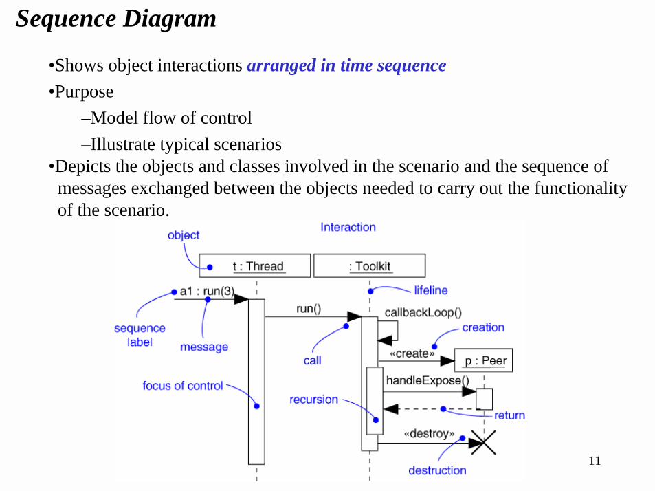
Sequence Diagram
•Shows object interactions arranged in time sequence•Purpose
–Model flow of control–Illustrate typical scenarios
•Depicts the objects and classes involved in the scenario and the sequence of messages exchanged between the objects needed to carry out the functionality of the scenario.
12
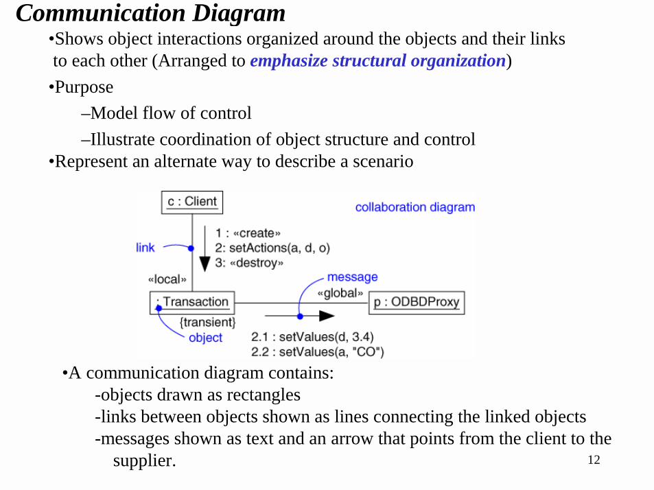
Communication Diagram•Shows object interactions organized around the objects and their links to each other (Arranged to emphasize structural organization)
•Purpose–Model flow of control–Illustrate coordination of object structure and control
•Represent an alternate way to describe a scenario
•A communication diagram contains:-objects drawn as rectangles-links between objects shown as lines connecting the linked objects-messages shown as text and an arrow that points from the client to the
supplier.
13
4. Dynamic Behavior
State Transition Diagram�Use cases and scenarios provide a way to describe system
behavior, that is the interaction between objects in the system.
�A state transition diagram allows the modeling of the behavior inside a single object.
÷It shows the events or messages that cause a transition from one state to another, and the actions that result from a state change.
÷It is created only for classes with significant dynamic behavior, like control classes.
14
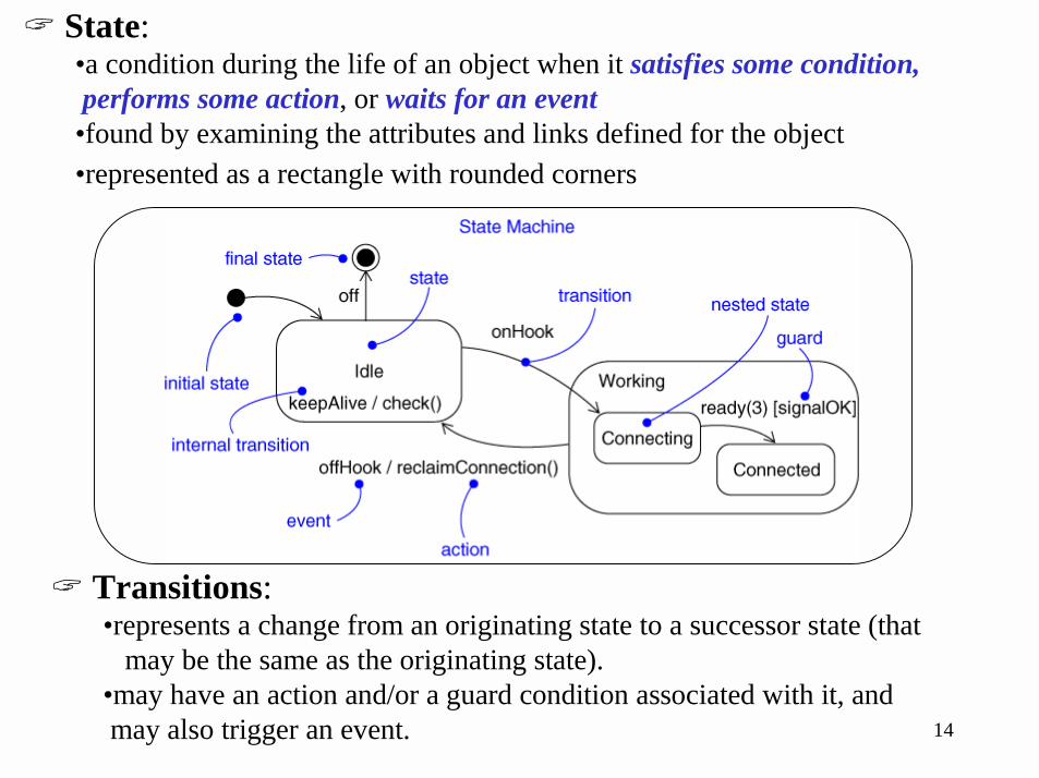
� State:•a condition during the life of an object when it satisfies some condition,performs some action, or waits for an event
•found by examining the attributes and links defined for the object•represented as a rectangle with rounded corners
� Transitions:•represents a change from an originating state to a successor state (that
may be the same as the originating state).•may have an action and/or a guard condition associated with it, andmay also trigger an event.
15
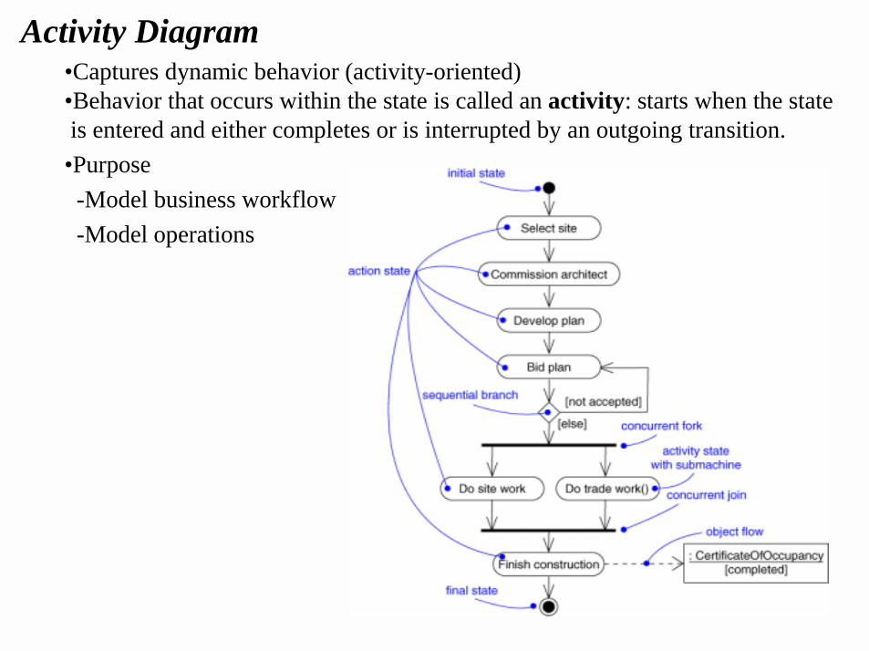
Activity Diagram•Captures dynamic behavior (activity-oriented)•Behavior that occurs within the state is called an activity: starts when the stateis entered and either completes or is interrupted by an outgoing transition.
•Purpose-Model business workflow-Model operations
16ForeignCustomer Bank
Officer
Validation
Customer
Query
Withdrawal
Deposit
Transfer
<<include>>
<<include>>
<<include>>
Bank Customer
Maintain
ATM System
Handle Exception
<<extend>>
Check PIN
<<include>>
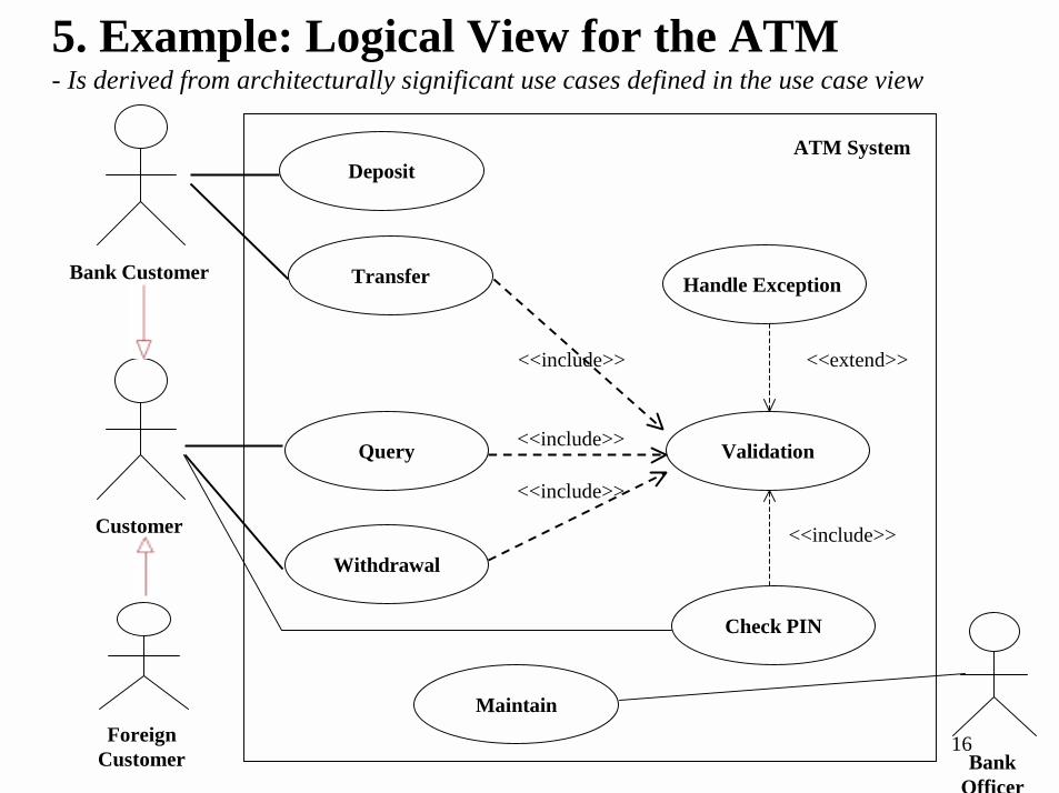
5. Example: Logical View for the ATM- Is derived from architecturally significant use cases defined in the use case view
17
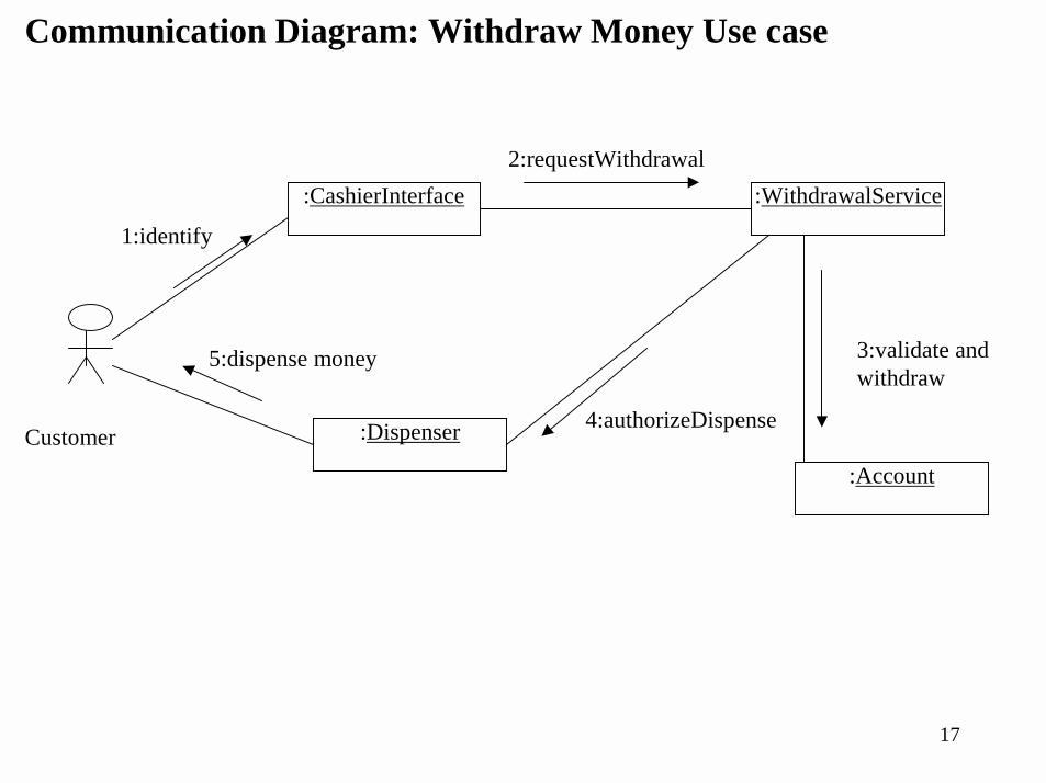
Communication Diagram: Withdraw Money Use case
Customer
:CashierInterface
:Dispenser
:WithdrawalService
:Account
1:identify
2:requestWithdrawal
5:dispense money 3:validate and withdraw
4:authorizeDispense
18
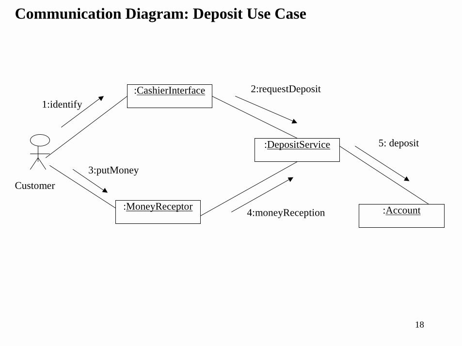
Communication Diagram: Deposit Use Case
:CashierInterface
:MoneyReceptor
:DepositService
:Account
Customer
1:identify2:requestDeposit
3:putMoney
4:moneyReception
5: deposit
19
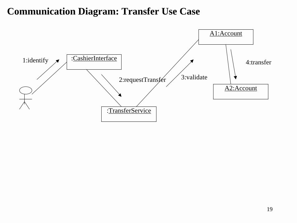
Communication Diagram: Transfer Use Case
:CashierInterface
:TransferService
A1:Account
A2:Account
1:identify
2:requestTransfer 3:validate
4:transfer
20
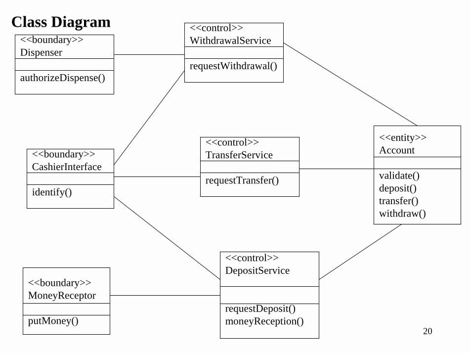
Class Diagram
<<boundary>>CashierInterface
identify()
<<boundary>>Dispenser
authorizeDispense()
<<boundary>>MoneyReceptor
putMoney()
<<control>>WithdrawalService
requestWithdrawal()
<<control>>TransferService
requestTransfer()
<<control>>DepositService
requestDeposit()moneyReception()
<<entity>>Account
validate()deposit()transfer()withdraw()
21
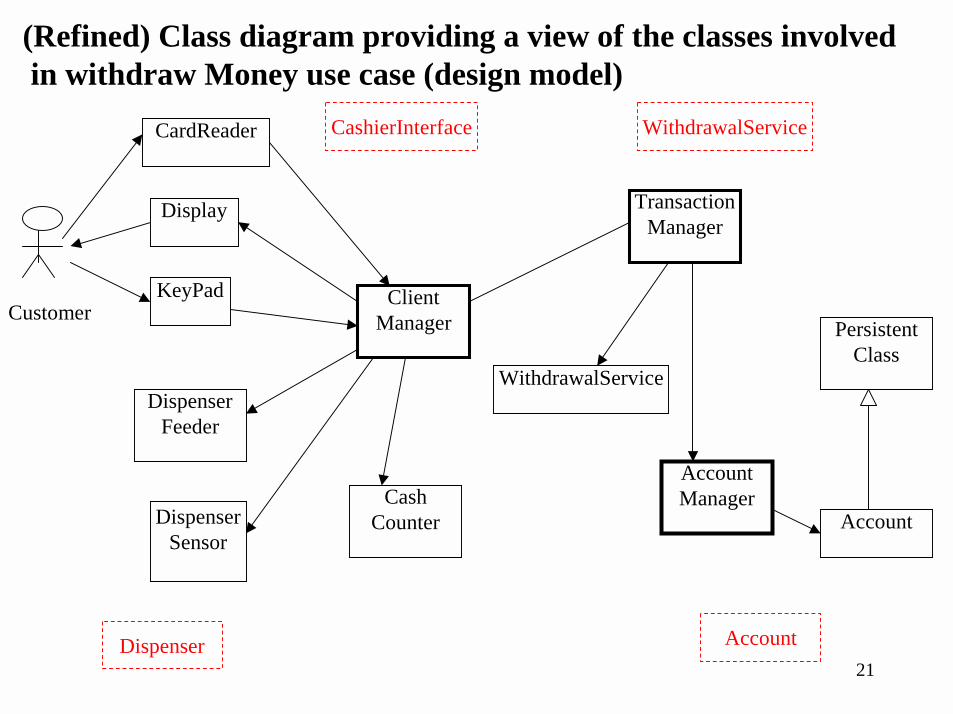
(Refined) Class diagram providing a view of the classes involvedin withdraw Money use case (design model)
DispenserSensor
DispenserFeeder
CashCounter
WithdrawalService
TransactionManager
Account
PersistentClass
AccountManager
Display
KeyPad
CardReader
ClientManagerCustomer
CashierInterface
Dispenser
WithdrawalService
Account
22
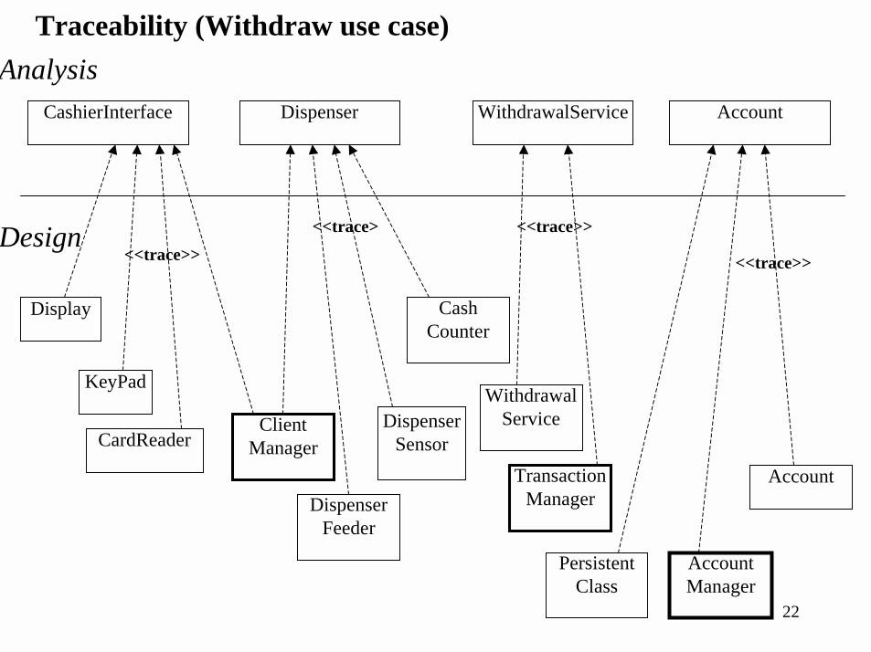
CashierInterface
Traceability (Withdraw use case)
Dispenser WithdrawalService Account
Analysis
Design
Display
KeyPad
CardReaderDispenser
Sensor
DispenserFeeder
CashCounter
ClientManager
WithdrawalService
TransactionManager
Account
PersistentClass
AccountManager
<<trace>> <<trace>>
<<trace> <<trace>>
23
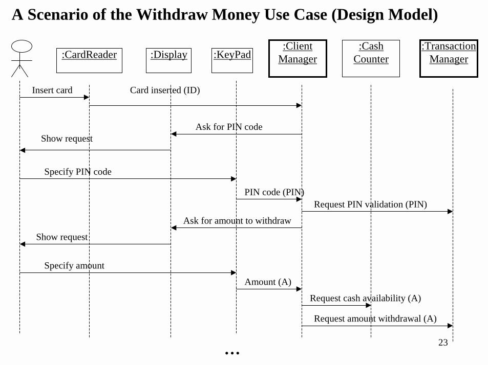
:Display :KeyPad:CardReader:Cash
Counter:Client
Manager:Transaction
Manager
A Scenario of the Withdraw Money Use Case (Design Model)
…
Insert card Card inserted (ID)
Ask for PIN codeShow request
Specify PIN code
PIN code (PIN)Request PIN validation (PIN)
Ask for amount to withdraw
Show request
Specify amount
Amount (A)
Request cash availability (A)
Request amount withdrawal (A)
24
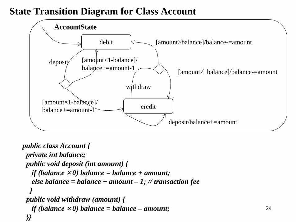
State Transition Diagram for Class Account
debit
credit
deposit
withdraw
deposit/balance+=amount
[amount ⁄ balance]/balance-=amount
[amount>balance]/balance-=amount
[amount×1-balance]/balance+=amount-1
[amount<1-balance]/balance+=amount-1
AccountState
public class Account {private int balance;public void deposit (int amount) {
if (balance ×××× 0) balance = balance + amount;else balance = balance + amount – 1; // transaction fee}
public void withdraw (amount) {if (balance ×××× 0) balance = balance – amount;
}}
25
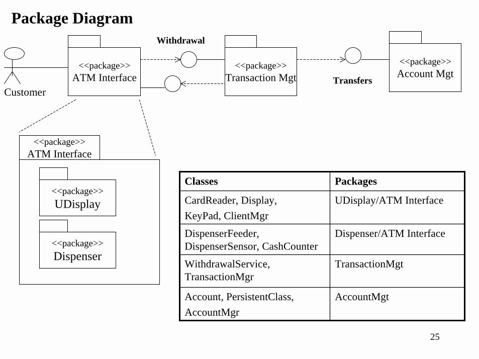
Package Diagram
AccountMgtAccount, PersistentClass,AccountMgr
TransactionMgtWithdrawalService, TransactionMgr
Dispenser/ATM InterfaceDispenserFeeder, DispenserSensor, CashCounter
UDisplay/ATM InterfaceCardReader, Display,KeyPad, ClientMgr
PackagesClasses
<<package>>ATM Interface
<<package>>UDisplay
<<package>>Dispenser
Transfers
Withdrawal
<<package>>ATM Interface
<<package>>Transaction Mgt
<<package>>Account Mgt
Customer
26
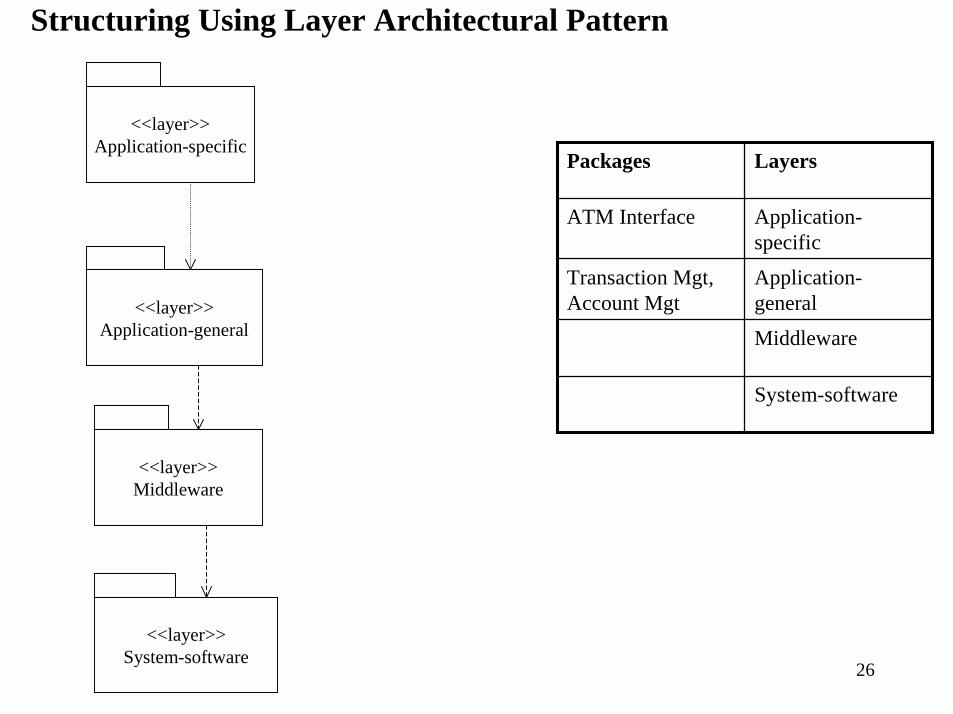
Structuring Using Layer Architectural Pattern
<<layer>>Application-specific
<<layer>>Application-general
<<layer>>Middleware
Middleware
System-software
Application-general
Transaction Mgt, Account Mgt
Application-specific
ATM Interface
LayersPackages
<<layer>>System-software
27
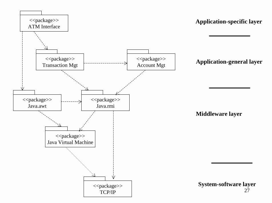
<<package>>ATM Interface
<<package>>Transaction Mgt
<<package>>Account Mgt
<<package>>Java Virtual Machine
<<package>>Java.rmi
<<package>>Java.awt
<<package>>TCP/IP
Application-specific layer
Application-general layer
System-software layer
Middleware layer
28
<<subsystem>>ATM Interface
<<subsystem>>Transaction Mgt
<<subsystem>>Account Mgt
<<subsystem>>Java Virtual Machine
<<subsystem>>Java.rmi
<<subsystem>>Java.awt
<<subsystem>>TCP/IP
Application-specific layer
Application-general layer
System-software layer
Middleware layer
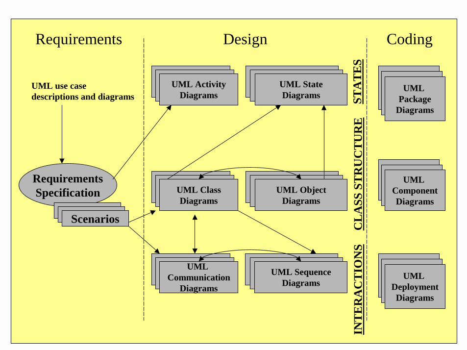
Requirements Design Coding
UML Package
Diagrams
UML ComponentDiagrams
UML DeploymentDiagrams
RequirementsSpecification
Scenarios
UML use casedescriptions and diagrams
UML ActivityDiagrams
UML StateDiagrams ST
ATE
S
UML ClassDiagrams
UML ObjectDiagrams
CLA
SS S
TRU
CTU
RE
UML Communication
Diagrams
UML SequenceDiagrams
INTE
RA
CTI
ON
S