Chap 03
53
Packet switching Protocols
-
Upload
shraddhabpatel -
Category
Education
-
view
82 -
download
0
Transcript of Chap 03

Packet switching Protocols

Introduction
• Two switching Techniques: Packet switching and Circuit Switching
• Circuit switching appeared in form of telephone network.
• Dynamic link bandwidth distribution of was not possible.
• Packet switching introduced to tackle enormous data traffic.
– Use of buffer memory PSNs permit efficient link bandwidth management
– but result delay in data traffic.
• Both networks switching technology have its own advantages and
disadvantages.

What is Packet switching ?
• Packet switching is data transmitting technique in which data to be
transmitted is divided into small fragments called packets.
• Packet transmitted to the destination through network channel is
provided
1) header containing the address of the source and destination
node, which is important to deliver packet.
2) trailer consist of the checksum, which allows you to check
whether information is corrupted during transmission.
3) central part of each packet consist original data.
• In PSN compare to the circuit switching network is always ready to
receive packet from any of its user,.
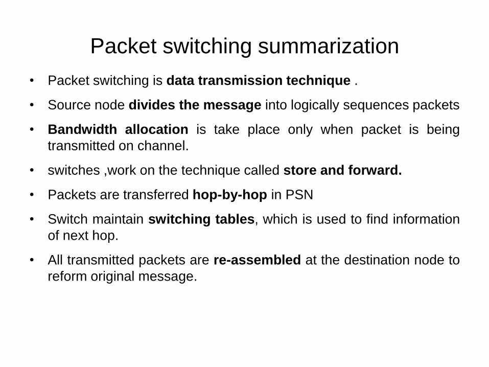
Packet switching summarization
• Packet switching is data transmission technique .
• Source node divides the message into logically sequences packets
• Bandwidth allocation is take place only when packet is being
transmitted on channel.
• switches ,work on the technique called store and forward.
• Packets are transferred hop-by-hop in PSN
• Switch maintain switching tables, which is used to find information
of next hop.
• All transmitted packets are re-assembled at the destination node to
reform original message.
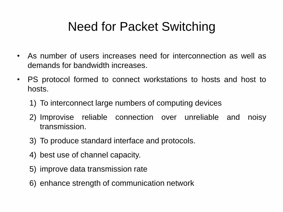
Need for Packet Switching
• As number of users increases need for interconnection as well as
demands for bandwidth increases.
• PS protocol formed to connect workstations to hosts and host to
hosts.
1) To interconnect large numbers of computing devices
2) Improvise reliable connection over unreliable and noisy
transmission.
3) To produce standard interface and protocols.
4) best use of channel capacity.
5) improve data transmission rate
6) enhance strength of communication network

Working
• PSN contains switches same as CSN but working is different.
• In PSN ,Packet Switch has
• 1) Internal buffer :
– Sore and forward packets containing header,payload,trailer
part.
– packets are placed into input buffer if information contained in
the header and trailer part of the packets are found correct.
– Buffering is essential for synchronizing the speed of arriving of
packets and their switching
– Buffer size should not be greater than the size of single packet to
store the input.

Queue processing in Switch

Methods for Packet Switching
Packet Switched Networks
Connection lessPacket Switching
Connection-oriented
Packet Switching
Datagram Transmission
Logical Connection
Virtual circuit packet
switching
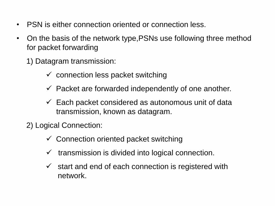
• PSN is either connection oriented or connection less.
• On the basis of the network type,PSNs use following three method
for packet forwarding
1) Datagram transmission:
connection less packet switching
Packet are forwarded independently of one another.
Each packet considered as autonomous unit of data
transmission, known as datagram.
2) Logical Connection:
Connection oriented packet switching
transmission is divided into logical connection.
start and end of each connection is registered with
network.

Processing for entire set of packets as logical
connection rather than separately for each packets.
3) Virtual Circuit Packet Switching:
Connection oriented
connection parameter includes delivery route
All transmitted packet follow same route for that (logical)
connection
This distinct, predefined route connecting end nodes in
PSN is known as Virtual circuit.
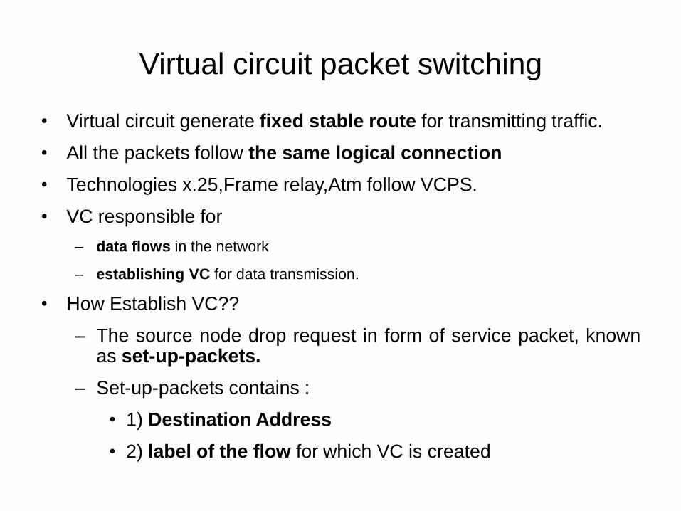
Virtual circuit packet switching
• Virtual circuit generate fixed stable route for transmitting traffic.
• All the packets follow the same logical connection
• Technologies x.25,Frame relay,Atm follow VCPS.
• VC responsible for
– data flows in the network
– establishing VC for data transmission.
• How Establish VC??
– The source node drop request in form of service packet, knownas set-up-packets.
– Set-up-packets contains :
• 1) Destination Address
• 2) label of the flow for which VC is created
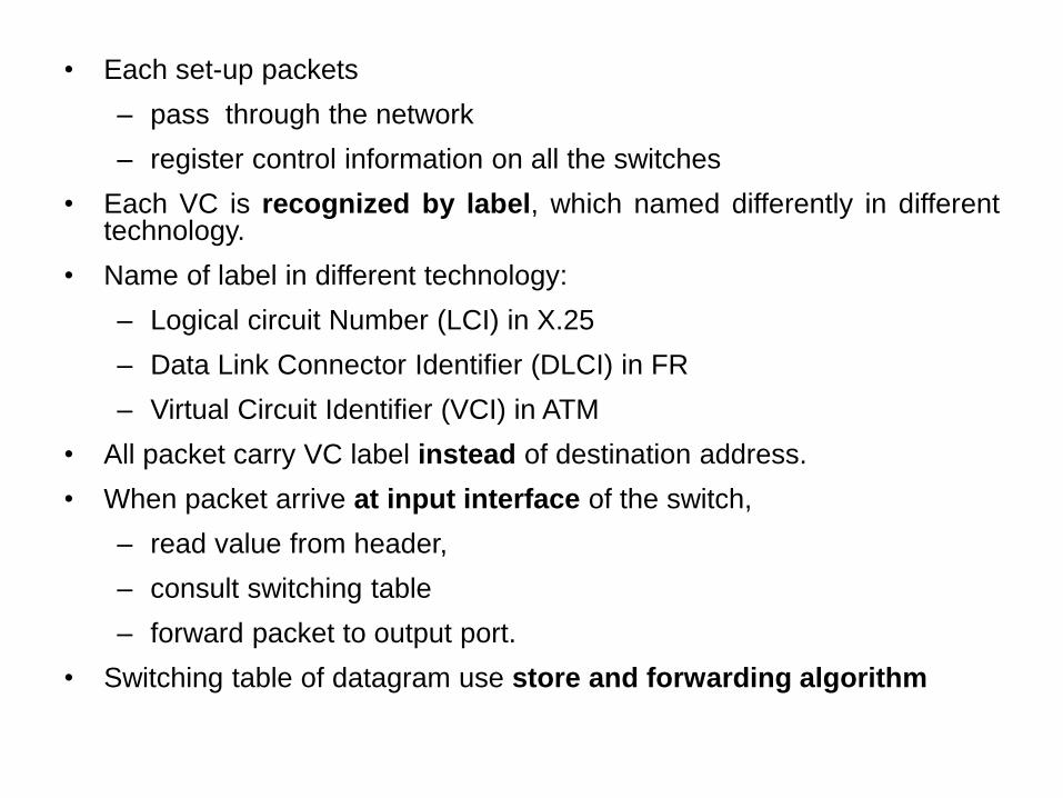
• Each set-up packets
– pass through the network
– register control information on all the switches
• Each VC is recognized by label, which named differently in differenttechnology.
• Name of label in different technology:
– Logical circuit Number (LCI) in X.25
– Data Link Connector Identifier (DLCI) in FR
– Virtual Circuit Identifier (VCI) in ATM
• All packet carry VC label instead of destination address.
• When packet arrive at input interface of the switch,
– read value from header,
– consult switching table
– forward packet to output port.
• Switching table of datagram use store and forwarding algorithm

• Switching table in VC make entry only on VC passing through
switch.
• VC carry less overhead since label is shorter than destination
address.

Virtual Circuit Technologies
• 1) X.25 :
– Used virtual circuit for reliable data transmission.
– Had a potential for restoring lost and damaged packets
transmitted in network.
• 2) Frame Relay:
– Working similar to Ethernet in LAN.
– Consist reduced set of function than x.25 for delivering frame to
destination.
– FR also supports high quality voice transmission.
• 3) ATM :
– Introduced for transmission of data ,voice and audio and object
control.
– Popular due to its performances and scalability.
– High price and difficulty in processing cells at high transmission
rate.

Introducing X.25
• X.25 protocols for VCPS.
• X.25 used to offer users with WAN connecting across Pubic Data
Networks(PDN).
• X.25 is communication technology over slow, analog , and noisy
telecommunication links.
• X.25 provides
• end-to end error detection
• correction as solution to limit the data loss due to high bit rate.
• Error correction by retransmitting the lost packets.
• Boost in speed and quality of communication links limited use of
x.25.
• But x.25 always serve as basis for comparison and foundational
packet switching technology.

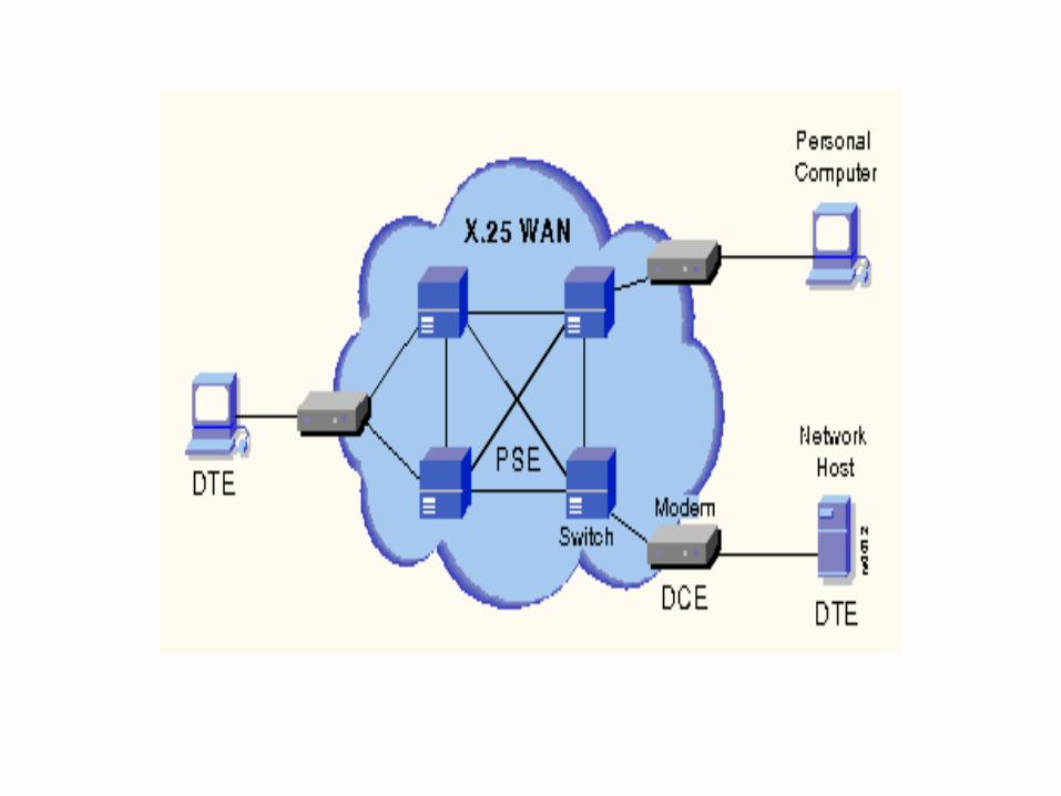
X.25 Equipment
• Data Terminal Equipment(DTEs): Equipment serving as data
source or data sink.
• Data Circuit Terminating Equipment (DCEs): offer functions
required to create, sustain and stop a connection and signal
conversion.e.g modem works as DCE.
• Packet Switching Exchanges(PSE): switches that create most of
the carrier’s network and transmit data from one DTE to another
DTE through X.25 PSN.
• Packet Assembler/Disassembler(PAD): usually used in x.25
– Used between DTE and DCE devices.
– Buffering: storing data until a device is ready to process data.
– Packet assembly: adding header with the data to form a Packet
– Packet Disassembly: removing data and header apart in a
packet.

Working of PAD

X.25 Virtual Circuit
• Two types of VC are used in x.25 PSN.
1) Switched Virtual Circuit(SVCs):
short term connection between two DTEs.
SVCs are similar to the telephone calls.
first, connection is formed, then data is transmitted
and finally connection is stopped.
Each DTE is assigned a distinct DTE address ,which can be
utilized similar to telephone number.

2) Permanent Virtual Circuits(PVCs):
– Refer to fixed connection between two DTES.
– Means if there is a regular and constant data transmission
between DTEs across PSN
– setting up connection and path every time, is more efficient to
PSN.
– It is very much similar to leased line where the connection
always exists.
– Hence ,data may always be transmitted without any call setup.

Architecture of X.25
• Basic idea behind the development of X.25 was to create global
PSN.
• The basic layers were present in X.25 Architecture:
• 1) Physical Level:
– Works with the physical interface between the nodes of the
network.
– Operate between a DTEs and the link that joins the DTE to
packet switching node.
– X.21 is a standard protocol used for physical layer.
• 2) Link level :
– Provide reliable transmission of information across the physical
link.

– Link level transfer data traffic as a sequences of frames and
– Uses a subset of high level data link control(HDLC) known asLink Access protocol balanced(LAPB) which is bit orientedprotocol.
• 3) Packet Level :
– Carries end –to- end connection between DTEs.
– Functions:
– Establishing connection
– Transferring data
– Terminating a Connection
– Error and Flow control
– Information is transmitted in packets through VCs using x.25 packet level.
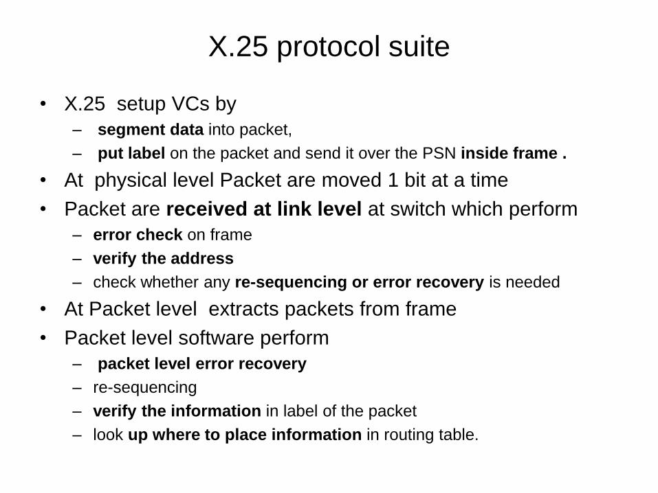
X.25 protocol suite
• X.25 setup VCs by
– segment data into packet,
– put label on the packet and send it over the PSN inside frame .
• At physical level Packet are moved 1 bit at a time
• Packet are received at link level at switch which perform
– error check on frame
– verify the address
– check whether any re-sequencing or error recovery is needed
• At Packet level extracts packets from frame
• Packet level software perform
– packet level error recovery
– re-sequencing
– verify the information in label of the packet
– look up where to place information in routing table.
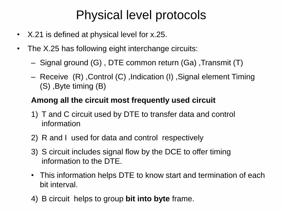
Physical level protocols
• X.21 is defined at physical level for x.25.
• The X.25 has following eight interchange circuits:
– Signal ground (G) , DTE common return (Ga) ,Transmit (T)
– Receive (R) ,Control (C) ,Indication (I) ,Signal element Timing
(S) ,Byte timing (B)
Among all the circuit most frequently used circuit
1) T and C circuit used by DTE to transfer data and control
information
2) R and I used for data and control respectively
3) S circuit includes signal flow by the DCE to offer timing
information to the DTE.
• This information helps DTE to know start and termination of each
bit interval.
4) B circuit helps to group bit into byte frame.
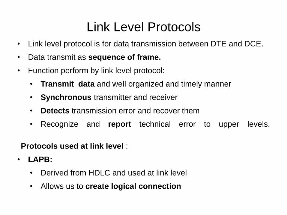
Link Level Protocols
• Link level protocol is for data transmission between DTE and DCE.
• Data transmit as sequence of frame.
• Function perform by link level protocol:
• Transmit data and well organized and timely manner
• Synchronous transmitter and receiver
• Detects transmission error and recover them
• Recognize and report technical error to upper levels.
Protocols used at link level :
• LAPB:
• Derived from HDLC and used at link level
• Allows us to create logical connection

• Link Access Protocol (LAP) : prior edition of LAPB
• Link Access Procedure , D channel:
– Derived from LAPB
– Used for ISDNs
– Provide transmission between two DTEs through D channel
• Logical Link Control (LLC):
– Allow x.25 packets to transferred over a LAN channels
– Denote a protocol that is institute of electronics and electrical
engineering 802 LAN protocol.
• Information Frame (I-Frame):
– contains data information as well as control information that is being
transferred between sender and receiver.
– Control frame contain frame sequence number, send sequence
numbers(SSNs) and RSNs
– Functions: sequencing, Flow control, error detection and recovery.

Packet Level Protocols(PLP)
• Manages end-to-end communication between various DTEs.
• Each PLP packets contain four types of field:
1) General Format Identifier(GFI):Contains information about
– Type of data and control information
– Type of windowing used
– Packet delivery conformation is essential or not
2) Logical Channel Identifier (LCI):
– Identifier that uniquely identifies the virtual circuit across DTE or DCE
3) Packet Type Identifier(PTI): identifies the PLP packet type
4) User Data :Data that retain information of upper layers
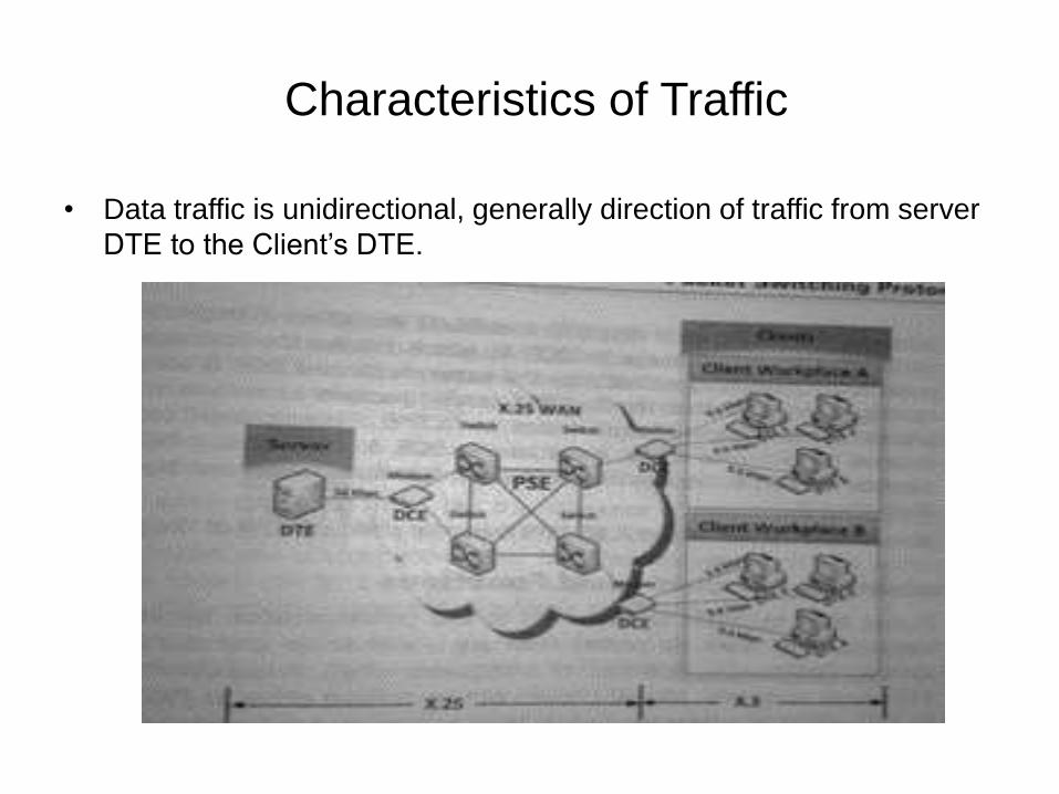
Characteristics of Traffic
• Data traffic is unidirectional, generally direction of traffic from server
DTE to the Client’s DTE.
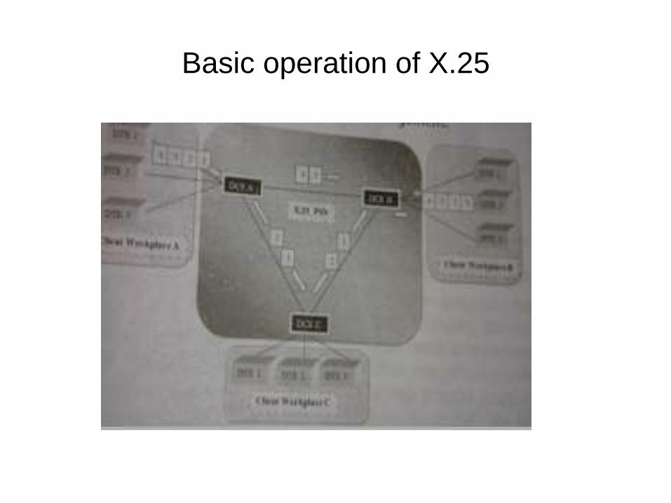
Basic operation of X.25

Packet Level Functions
• Functions that works on packet level: call set-up and clearing, data
transfer and flow control.
• Packets are delivered in sequence when virtual circuit is used.
• Virtual circuit are created
– PVC which is static circuit
– SVC which is dynamic circuit.
• Data packets and call control packets are handle by PVCs and
SVCs.
• X.25 global address is used
– establish call to communicate with remote interface in the network
– call breakup.
– X.25 globally significant
• SVC channel number is assigned between each switch which is
locally significant.
• All data packets transmitted in call set-up and breakup are
recognized by the SVC channel number.

Different Modes in X.25 packet transfer
sequence
1) Call setup mode :
refer to a mode that sets up SVCs between DTEs.
2) Data Transfer Mode:
facilitate data transmission between two DTEs.
3) Idle Mode: refer to a mode that is applied when virtual circuit has
been established but no data is begin transferred between DTEs.
4) Call clearing mode: refer to a mode that ends up communication
session between DTEs and removes SVCs as well.
5) Restarting mode: refer to a mode that synchronizes data transfer
between DTE and DCE.

X.25 control packet format
1 2 3 4 5 6 7 8
General Format Identifier Logical channel Group Number
Logical Channel Number
Control Packet Type Identifier 1
Variable Type

Normal Data Packet Format
1 2 3 4 5 6 7 8
Logical channel Group Number
Logical Channel Number
RSN SSN 0M
Q D 0 1
User Data Field

Windowing and Flow control
• Windowing needed for efficient transmission of data packets and
implement flow control in PSN.
• Flow Control: determine amount of data deliver without receiving
acknowledgement from receiver.
• In X.25 SSNs and RSNs used to present flow control between the
packet-level sender and receiver.

Fast Connect Option
• Fast packet transaction is possible in X.25 with help of connect
option.
• Options:
• 1) Fast select call: from Clients contains both• call request packet and user data packet
– Server can react with
• call accept packet that encloses user data from server.
2) Fast select with immediate clear: refer to the option where
call request packet : sets up the connection
clear indication packet : stops the connection.
X.75-Internetworking Protocol
• X.75 describe the protocol format and process for internetworking
several x.25 packet switching private data network together.
• It interconnect larger backbone switches.
• X.75 and x.121 together offer address translation.
• A numbers of countries posses private and public PSNs and use
x.75 to link these networks.

Advantages of X.25 PSN
• Perform packet format conversion, code conversion, speed
conversion between DTEs.
• Forms packets of different size of messages, which do not interface
with each other.
• Provides
– fast exchange of short messages
– naturals secure data transfer scheme
– steady delay of long messages
– Present network functions that are not visible to users
– both asynchronous and synchronous interface
– better switching technology than circuit switching
– global connectivity with reduced cost circuit.

Disadvantages
• Limited access Speed
• High delay potential
• High overhead that decrease valuable throughput
Switched Multimegabit Data Service
• SMDC is connectionless ,cell-switched public data service that facilitate
data to be switched between multiple public-addressed subscribers.
• provides a technique of high speed LAN and MAN interconnection
across WAN
• SMDS is most cost effective and capable than using a dedicated
network.
• Provide facility to virtually extend LAN across MAN and WAN.
• SMDS,while working with modern packet protocols, does not provide
network error correction.
• So ,it require retransferring of data over low loss digital and fiber optics
network.

SMDS Network Components
1) Customer Premises Equipment (CPE) :
– possessed and maintained by the customer.
– Consist of end equipment such as terminals, as well as
intermediate nodes such as routers,modems,multiplexers.
– Intermediate nodes are categorized in SMDS carrier equipment.
2) Carrier Equipment :
– contains High speed WAN switches that should be convention to
network equipment specification which describe network
operations.
– equipments: used between local carrier network and long
distance network and between two switches inside a single
carrier network.
3) Subscriber Network Interface(SNI) : refer to an interface between
CPE and carrier equipment where customer network finish and
carrier network initiate.

Compare with OSI reference model
Network Layer
Network Layer 802.1
Data Link Layer
LLC Sublayer
MAC sublayer
802.2
Physical Layer
Physical Layer
Ethernet802.3
Token bus802.4
Token Ring802.5
SMDS802.6
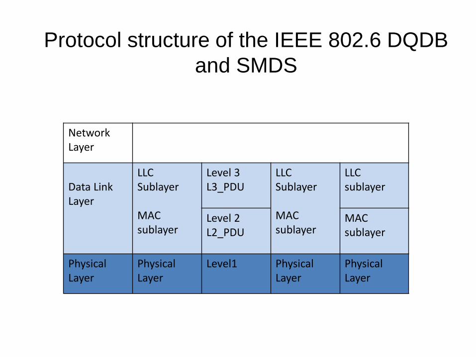
Network Layer
Data Link Layer
LLC Sublayer
MAC sublayer
Level 3L3_PDU
LLC Sublayer
MAC sublayer
LLC sublayer
Level 2L2_PDU
MAC sublayer
Physical Layer
Physical Layer
Level1 Physical Layer
Physical Layer
Protocol structure of the IEEE 802.6 DQDB
and SMDS

DQDB-(Distributed Queue Dual Bus)
• Man protocol used for data link layer communication.
• DQDB describes a network topology made up of two unidirectional
logical buses that join several systems.
• The access DQDB defines only the functions of the DQDB across a
user network interface.
• The access of DQDB made up of following basic SMDS network
components:
• 1) Carrier Equipment: Switch in SMDS network that works as one
station on the bus
• 2)CPEs: function as station on bus
• 3)SNI : works as an interface between the CPE and the carrier
equipment.

Access of DQDB with two CPE devices and
one Switch
•
SNI
SMDS
WAN
Computer Router
CPE Customer Premises Equipment
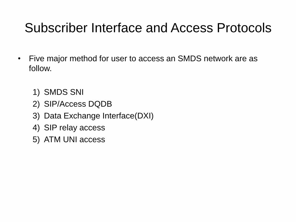
Subscriber Interface and Access Protocols
• Five major method for user to access an SMDS network are as
follow.
1) SMDS SNI
2) SIP/Access DQDB
3) Data Exchange Interface(DXI)
4) SIP relay access
5) ATM UNI access

SNI
• Defined as Physical and administrative interface of the subscribers
• Placed at the boundary of an SMDS network.
• Provides utility for CPE to interface an SMDS network.
• SNI access technique utilize the access DQDB protocol and
standard channel service Unit/Data service Unit(CSU/DSU).

SIP
• SIP offers numbers of CPEs that communicate over the SNI
applying the access DQDB.
• It exchange L3_PDUs between CPE and SMDS network switching
nodes known as access DQDB which is differentiated as CPE-to-
MAN switching system access as opposed to switching-system to
switching system access.
• The SMDS access DQDB follows the open bus topology.
• Many CPEs can be connected to a single access DQDB through
E1,E3,DS1 or DS3 circuits.
• Some of the most frequently used CPEs are bridges,router,switches.
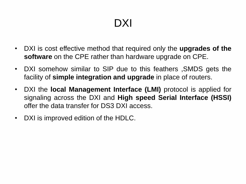
DXI
• DXI is cost effective method that required only the upgrades of the
software on the CPE rather than hardware upgrade on CPE.
• DXI somehow similar to SIP due to this feathers ,SMDS gets the
facility of simple integration and upgrade in place of routers.
• DXI the local Management Interface (LMI) protocol is applied for
signaling across the DXI and High speed Serial Interface (HSSI)
offer the data transfer for DS3 DXI access.
• DXI is improved edition of the HDLC.
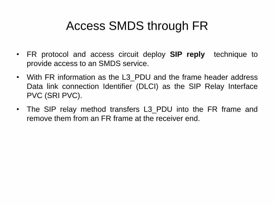
Access SMDS through FR
• FR protocol and access circuit deploy SIP reply technique to
provide access to an SMDS service.
• With FR information as the L3_PDU and the frame header address
Data link connection Identifier (DLCI) as the SIP Relay Interface
PVC (SRI PVC).
• The SIP relay method transfers L3_PDU into the FR frame and
remove them from an FR frame at the receiver end.
Access SMDS Through ATM
• SMDS service offered over ATM network by using ATM interface.
• ATM VCC connectivity for access to SMDS service through an ATM
UNI access protocol.
• SIP option for ATM access ,which permit us use of one or more
VCCs to be assigned as SMDS SIPs.
• FIG.

Addressing and Traffic Control
• SMDS addressing scheme utilizes E.164 numbering scheme andinclude 15 digit addresses.
• This scheme was selected for quick integration of SMDS into thetelephone network addressing .
• Source and destination address have 15 digit preserved to containany E.164 address.
• The NANP has 10 digit numbering plans, however it increase 1more and make total 11 digits to signify for global use.
• SMDS utilize 7 bit- describe switching system used to find outindividuals and group addresses. 4 bit- utilized to locate a specificaccess line on the switching system.
• CPE interface technique to access CPE equipment.
• Unique address are assigned to each SNI by SMDS serviceprovider.
• Subscriber receive full control over the each individual address
and May give multiple SMDS addresses per CPE.
• SMDS give a single group address to multiple equipment to
multicast their data to other members of their group address.
• Each SNI can be associated with up to 16 subscribers.

Group Addressing
• SMDS facilitate either point to point packet delivery or point to
multipoint packet delivery.
• 1) Unicast Addressing: Denotes point-to point datagram delivery
service.
• 2) Multicast Addressing: Denotes point-to multipoint datagram
delivery service.