Chaos Control
5
Control of Chaos by Resonant Parametric Perturbation in a Current Mode Controlled Buck- Boost Dc-Dc Converter A.KAVITHA 1 , G.UMA 2 1. Lecturer, EEE Dept., CEG, Anna University, E-mail: akavitha@annauni v.edu 2. Assistant Professor, EEE Dept., CEG, Anna University, E-mail: [email protected] Abstract- Resonant parametric perturbation (RPP) method is an effective non-feedback method for controlling chaos. In this paper, the above method is applied for the voltage control of a current programmed buck-boost DC-DC converter which has been known to easily become chaotic for wide parameter variations. The different possible operating regimes leading to chaotic operation of the current mode controlled buck-boost converter has been discussed and the control of output voltage by RPP method is demonstrated through computer simulations and experimental studies. The converter has been stabilized to period-1 operation practically . Keywords: - Resonant parametric perturbation, Chaos, buck-boost DC-DC converter I. I NTRODUCTION Chaotic behavior has been identified in many physical and engineering systems. In particular it has been observed that a large number of power electronic systems exhibit chaos. [1-3]. When chaos is found undesirable for a particular system, as would be the case for most engineering applications, controlling it becomes necessary to avoid harmful consequences. Various methods have been proposed for the control of chaos. They can be classified into two general categories [4], namely feedback control methods and non- feedback control methods. Examples of feedback control methods include the Ott-Grebogi- Yorke method, Occasional proportional feedback method and time delayed feedback method. Examples of non-feedback methods include adaptive control, resonant parametric perturbation, and weak periodic perturbation method. Compared to the feedback type of control, the non-feedback type of control is simple and suitable for practical implementations. Attention in this paper has been focused on the non-feedback type of control for controlling chaos. The resonant parametric perturbation method has been considered for controlling chaos in a current mode controlled buck-boost converter and show that an unstable period-1 orbit in the chaotic attractor can be stabilized. II. REVIEW OF RESONANT PARAMETRIC PERTURBATION: Resonant parametric perturbation can suppress chaos [5]. In general parametric perturbations can make a system chaotic, but applying it at appropriate frequencies and amplitudes can induce the system to stay in periodic regimes. Thus the resonant parametric perturbation is to perturb some parameters at appropriate frequencies and amplitudes, thereby converting a chaotic operation into a regular one. Usually a parameter that strongly affects the system and can be easily varied is chosen. Suppose this parameter is c. This parameter is then perturbed with the function (1+ αsin2πft) where α <<1 and f is the perturbation frequency to be chosen. This approach has been used by Lima and Pettini for stabilizing a chaotic Duffing-Holmes system [6]. In particular it has been shown that when the perturbation frequency f resonates with the periodic driving frequency f s , chaos subsides and periodic state e merges. III.APPLICATION OF RESONANT PARAMETRIC PERTURBATION TO CONTROL CHAOS IN DC-DC CURRENT MODE CONTROLLED BUCK-BOOST CONVERTER: 3.1 Overview of circuit operation: The current mode controlled buck-boost converter [7] is shown in Fig.1.The switch is turned on periodically by the clock and off according to the output of a comparator that compares the inductor current i L with the reference current i ref . Figure 1. Circuit diagram of current mode controlled buck-boost DC-DC converter 978-1-4244-1 874-9/08/$25.00 ©2008 IEEE 323 Authorized licensed use limited to: BIRLA INSTITUTE OF TECHN OLOGY AND SCIENCE. Downloade d on August 14,2010 at 10:08:58 UTC from IEEE Xplore. Restrictions apply.
-
Upload
kautilya1987 -
Category
Documents
-
view
223 -
download
0
Transcript of Chaos Control

8/8/2019 Chaos Control
http://slidepdf.com/reader/full/chaos-control 1/5
Control of Chaos by Resonant Parametric
Perturbation in a Current Mode Controlled Buck-
Boost Dc-Dc Converter
A.KAVITHA1, G.UMA2 1. Lecturer, EEE Dept., CEG, Anna University, E-mail: [email protected]
2. Assistant Professor, EEE Dept., CEG, Anna University, E-mail: [email protected]
Abstract- Resonant parametric perturbation (RPP) methodis an effective non-feedback method for controlling chaos. Inthis paper, the above method is applied for the voltage controlof a current programmed buck-boost DC-DC converter whichhas been known to easily become chaotic for wide parametervariations. The different possible operating regimes leading tochaotic operation of the current mode controlled buck-boostconverter has been discussed and the control of output voltageby RPP method is demonstrated through computersimulations and experimental studies. The converter has beenstabilized to period-1 operation practically.
Keywords: - Resonant parametric perturbation, Chaos,buck-boost DC-DC converter
I. I NTRODUCTION
Chaotic behavior has been identified in many
physical and engineering systems. In particular it has been
observed that a large number of power electronic systems
exhibit chaos. [1-3]. When chaos is found undesirable for a
particular system, as would be the case for most engineering
applications, controlling it becomes necessary to avoid
harmful consequences.
Various methods have been proposed for the
control of chaos. They can be classified into two general
categories [4], namely feedback control methods and non-
feedback control methods. Examples of feedback control
methods include the Ott-Grebogi-Yorke method, Occasional
proportional feedback method and time delayed feedback
method. Examples of non-feedback methods include
adaptive control, resonant parametric perturbation, and
weak periodic perturbation method. Compared to the
feedback type of control, the non-feedback type of control is
simple and suitable for practical implementations.
Attention in this paper has been focused on thenon-feedback type of control for controlling chaos. The
resonant parametric perturbation method has been
considered for controlling chaos in a current mode
controlled buck-boost converter and show that an unstable period-1 orbit in the chaotic attractor can be stabilized.
II. REVIEW OF RESONANT PARAMETRIC
PERTURBATION:
Resonant parametric perturbation can suppress
chaos [5]. In general parametric perturbations can make a
system chaotic, but applying it at appropriate frequencies
and amplitudes can induce the system to stay in periodic
regimes. Thus the resonant parametric perturbation is to
perturb some parameters at appropriate frequencies and
amplitudes, thereby converting a chaotic operation into a
regular one.
Usually a parameter that strongly affects the
system and can be easily varied is chosen. Suppose this
parameter is c. This parameter is then perturbed with the
function (1+ αsin2πft) where α <<1 and f is the perturbation
frequency to be chosen. This approach has been used by
Lima and Pettini for stabilizing a chaotic Duffing-Holmes
system [6]. In particular it has been shown that when the
perturbation frequency f resonates with the periodic driving
frequency f s, chaos subsides and periodic state emerges.
III.APPLICATION OF RESONANT PARAMETRIC
PERTURBATION TO CONTROL CHAOS IN DC-DC CURRENT MODE CONTROLLED BUCK-BOOST
CONVERTER:
3.1 Overview of circuit operation:
The current mode controlled buck-boost converter [7] is shown in Fig.1.The switch is turned on periodically by
the clock and off according to the output of a comparator that compares the inductor current iL with the reference
current iref .
Figure 1. Circuit diagram of current mode controlled buck-boost DC-DCconverter
978-1-4244-1874-9/08/$25.00 ©2008 IEEE 323
Authorized licensed use limited to: BIRLA INSTITUTE OF TECHNOLOGY AND SCIENCE. Downloaded on August 14,2010 at 10:08:58 UTC from IEEE Xplore. Restrictions app

8/8/2019 Chaos Control
http://slidepdf.com/reader/full/chaos-control 2/5
While the switch is on, the inductor current climbs
up, and as it reaches iref , the switch is turned off, thereby
causing the inductor current to ramp down till the next clock
comes. This behavior is illustrated in Fig.2. It has beenassumed that the converter operates in continuous current
mode. There are two circuit configurations according towhether the switch is closed or open.
When switch S is closed, the state equations are (1) and (2):
L
E
dt
diL = (1)
cc v
RC
1
dt
dv−= (2)
Figure.2 Inductor current and Capacitor voltage waveforms of the currentmode controlled buck-boost DC-DC converter
When switch S is opened, the state equations are (3) and (4)
cL v
L
1
dt
di−= (3)
cL
c vRC
1-i
C
1
dt
dv= (4)
There are two state variables, inductor current iL
and capacitor voltage vc. Sampled data modeling in the formof stroboscopic map has been adopted, where the state
variables are observed in synchronism with clock. Let the
state variables at a clock instant be in and vn and those at thenext instant is in+1 and vn+1.
There are two ways in which the state can movefrom one clock instant to the next [8]. A clock pulse may
arrive before the current reaches iref . In this case the map
can be obtained by solving the equations for the on state
with in and vn as the initial conditions. These yields,
L
Tvii in
n1n +=+ (5)
RC
T
n1n evv
−
+ = (6)
If the inductor current reaches iref before the arrival of nextclock pulse, the map would include an on and off interval.
The map is obtained by stacking the solutions of on and off time equations:
))tT(sinc)tT(cosc(ei n2n1
)tT(
1nn −β+−β= −α
+
(7)
)]tT(sin)cc(
)tT(cos)cc[(ev
n12
n21
)tT(
1nn
−ββ−α
+−ββ+α= −α+
(8)
Where,2RC
1α −= , 1
L
C4R
2RC
1β
2
−= ,
ref 1 ic = ,
⎟⎟⎟
⎠
⎞
⎜⎜⎜
⎝
⎛ += αi
L
ev
β
1-c ref
RC
t
n2
n
3.2 Chaotic behavior:
Based on the map the chaos in buck-boost
converter has been studied. As the parameter iref is variedfrom 1A to 4A, the converter goes through period-1, period-
2, period-4, period-8 and eventually exhibit chaos. To verify
the theoretical analysis and simulation results, an
experimental circuit of a current mode controlled buck- boost converter has been built. For analyzing the chaotic
behavior, the reference current iref is varied. The circuit parameters are chosen as E=12V, L=1mH, C=4µF, R=20Ω,
T= 50µs (f s=20 kHz).The input voltage is kept at 12V. The
various possible operating regimes of the current
programmed buck-boost converter have been analyzed.
A. Period - 1 operation
With iref 0.3A, the buck-boost converter exhibits
fundamental period-1 waveform. The simulated andexperimental capacitor voltage waveforms and thecorresponding phase portrait are shown in Figures 3.11,
3.12 and 3.13 respectively.
Figure 3.11 Simulated capacitor voltage waveform of Period-1 operationwith iref =0.3A
Figure 3.12 Experimental capacitor voltage waveform of Period-1operation with iref =0.3A
324
Authorized licensed use limited to: BIRLA INSTITUTE OF TECHNOLOGY AND SCIENCE. Downloaded on August 14,2010 at 10:08:58 UTC from IEEE Xplore. Restrictions app

8/8/2019 Chaos Control
http://slidepdf.com/reader/full/chaos-control 3/5
Figure 3.31 Simulated capacitor voltage waveform of Period-4 operationwith iref =2A
Figure 3.13 Experimental phase portrait showing period-1 operation
B. Period - 2 operationWhen the reference current is increased further, the
converter enters into period-2 operation. By increasing the
value of iref to 1.86 A, the capacitor voltage waveform of the
Period-2 operation has been obtained. The simulation andhardware results showing Period-2 operation are shown in
Figures 3.21 and 3.22 respectively and the corresponding phase
portrait is shown in Figure 3.23.
Figure 3.21 Simulated capacitor voltage waveform of Period-2 operation withiref =1. 86A
Figure 3.22 Experimental capacitor voltage waveform of period-2 operationwith
iref =1. 86A
Figure 3.23 Experimental phase portrait showing Period-2 Operation
C. Period - 4 operation
By increasing the value of iref further to 2A, the
converter enters into Period-4 operation. The simulatedcapacitor voltage waveform and the experimental capacitor
voltage waveform of the converter are shown in Figures 3.31
and 3.32 respectively.
Figure 3.32 Experimental capacitor voltage waveform of Period-4 operationwith iref =2A
C. Chaotic operation
When the value of iref is further increased the
converter enters into chaotic regime. The simulated capacitor
voltage waveform and the experimental capacitor voltagewaveform are shown in Figure 3.41 and 3.42 respectively. The
experimental phase portrait showing chaotic operation has been shown in Figure 3.43.
Figure 3.41 Simulated capacitor voltage waveform of chaotic operation withiref =2.21A
Figure 3.42 Experimental capacitor voltage waveform of chaotic operationwith iref =2.21A
325
Authorized licensed use limited to: BIRLA INSTITUTE OF TECHNOLOGY AND SCIENCE. Downloaded on August 14,2010 at 10:08:58 UTC from IEEE Xplore. Restrictions app
8/8/2019 Chaos Control
http://slidepdf.com/reader/full/chaos-control 4/5
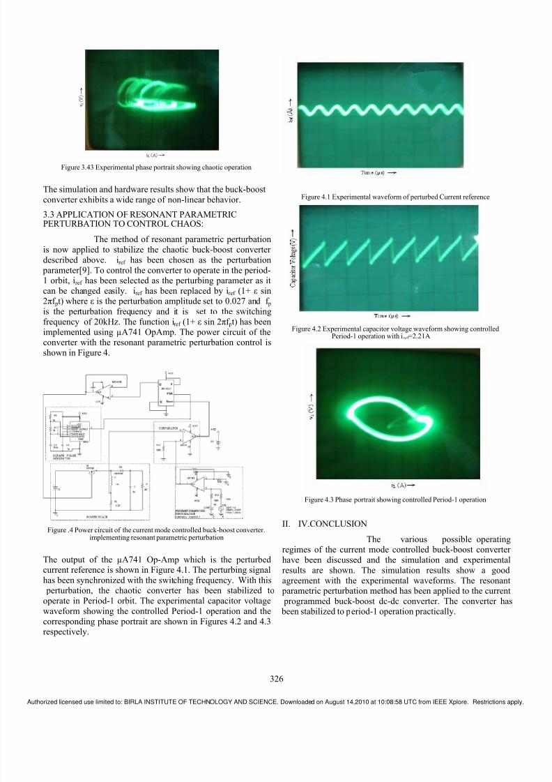
Figure 3.43 Experimental phase portrait showing chaotic operation
The simulation and hardware results show that the buck-boost
converter exhibits a wide range of non-linear behavior.
3.3 APPLICATION OF RESONANT PARAMETRIC
PERTURBATION TO CONTROL CHAOS:
The method of resonant parametric perturbation
is now applied to stabilize the chaotic buck-boost converter
described above. iref has been chosen as the perturbation
parameter[9]. To control the converter to operate in the period-1 orbit, iref has been selected as the perturbing parameter as it
can be changed easily. iref has been replaced by iref (1+ ε sin2πf pt) where ε is the perturbation amplitude set to 0.027 and f p
is the perturbation frequency and it is set to the switching
frequency of 20kHz. The function iref (1+ ε sin 2πf pt) has been
implemented using µA741 OpAmp. The power circuit of theconverter with the resonant parametric perturbation control is
shown in Figure 4.
Figure .4 Power circuit of the current mode controlled buck-boost converter.implementing resonant parametric perturbation
The output of the µA741 Op-Amp which is the perturbedcurrent reference is shown in Figure 4.1. The perturbing signal
has been synchronized with the switching frequency. With this perturbation, the chaotic converter has been stabilized to
operate in Period-1 orbit. The experimental capacitor voltage
waveform showing the controlled Period-1 operation and the
corresponding phase portrait are shown in Figures 4.2 and 4.3respectively.
Figure 4.1 Experimental waveform of perturbed Current reference
Figure 4.2 Experimental capacitor voltage waveform showing controlledPeriod-1 operation with iref =2.21A
Figure 4.3 Phase portrait showing controlled Period-1 operation
II. IV.CONCLUSION
The various possible operating
regimes of the current mode controlled buck-boost converter have been discussed and the simulation and experimental
results are shown. The simulation results show a good
agreement with the experimental waveforms. The resonant parametric perturbation method has been applied to the current
programmed buck-boost dc-dc converter. The converter has been stabilized to period-1 operation practically.
326
Authorized licensed use limited to: BIRLA INSTITUTE OF TECHNOLOGY AND SCIENCE. Downloaded on August 14,2010 at 10:08:58 UTC from IEEE Xplore. Restrictions app

8/8/2019 Chaos Control
http://slidepdf.com/reader/full/chaos-control 5/5