Chaos computing: a unified view -...
14
Chaos computing: a unified view Toshinori Munakata a *, Jun Takahashi b , Munehisa Sekikawa c and Kazuyuki Aihara de a Computer and Information Science Department, Cleveland State University, Cleveland, OH 44115, USA; b Aihara Electrical Engineering Co., Ltd, 2-16-8 Hama-cho, Funabashi-shi 273-0012, Japan; c Department of Bioengineering and Robotics, Graduate School of Engineering, Tohoku University, 6-6-01, Aza-Aoba, Aramaki, Aoba-ku, Sendai, 980-8579, Japan; d Institute of Industrial Science, The University of Tokyo, 4-6-1 Komaba, Meguro-ku 153-8505, Japan; e Aihara Complexity Modeling Project, ERATO, JST, 4-6-1 Komaba, Meguro-ku 153-8505, Japan Chaos computing is a non-traditional new paradigm that exploits the extreme non-linearity of chaotic systems. This article presents a unified theoretical view of chaos computing. It introduces the fundamental concept and the unique features that are characteristics of chaos computing, and discusses various implementation approaches. Basic aspects of digital chaos computing to realise logical gates are introduced, followed by two specific techniques: (1) direct utilisation of the threshold mechanisms; (2) an application of the chaos neuron model. After presenting these approaches, we discuss general characteristics of digital chaos computing. Other digital, analog and digital/analog hybrid forms of chaos computing are also considered. Potential advantages of chaos computing include: high speed, low power and low cost, a general-purpose form of computing, re-configurable or dynamic logical architecture, implementation of continuous logic, robustness against noise, and parallel and distributed computing. Keywords: new computing paradigms; chaos computing fundamentals; chaos computing theory; chaos neuron model; FPGA; parallel processing 1. Introduction Recently, there has been a growing interest for computing concepts based on new principles other than the traditional CMOS or silicon-based integrated circuit (so-called ‘silicon-based’) architecture [28]. While none of these new techniques has been seen as a possible replacement of the silicon-based architecture yet, these ideas have stimulated the scientific community by their fundamental nature, their intrinsic novelty, and their potential as the basis for new forms of information processing and applications. This article presents a unified theory of chaos computing, one of these new paradigms. Our primary focus is on the theoretical aspects rather than the physical implementation issues, which are beyond the scope of this article. The study of chaotic systems, or chaos in short, has attracted much attention for the past 30 years or so. Chaos represents a deterministic dynamical system that is non-linear, sensitive to initial conditions and that exhibits sustained irregularity. There are abundant candidates for chaos computing since chaos is all around us and is found in many disciplines, such as engineering, physics, chemistry and biology. For example, chaotic phenomena are found in lasers, electronic circuits and chemical and biological systems. There is another reason to support high feasibilities of chaos computing: the versatility ISSN 1744-5760 print/ISSN 1744-5779 online q 2010 Taylor & Francis DOI: 10.1080/17445760902774898 http://www.informaworld.com *Corresponding author. Email: [email protected] International Journal of Parallel, Emergent and Distributed Systems Vol. 25, No. 1, February 2010, 3–16 Author Posting. (c) 2010 Taylor & Francis, 2010. This is the author's version of the work. It is posted here by permission of Taylor & Francis for personal use, not for redistribution. The definitive version was published in International Journal of Parallel, Emergent and Distributed Systems, Volume 25 Issue 1, February 2010. doi:10.1080/17445760902774898 (http://dx.doi.org/10.1080/17445760902774898)
Transcript of Chaos computing: a unified view -...
Chaos computing: a unified view
Toshinori Munakataa*, Jun Takahashib, Munehisa Sekikawac and Kazuyuki Aiharade
aComputer and Information Science Department, Cleveland State University, Cleveland, OH 44115,USA; bAihara Electrical Engineering Co., Ltd, 2-16-8 Hama-cho, Funabashi-shi 273-0012, Japan;cDepartment of Bioengineering and Robotics, Graduate School of Engineering, Tohoku University,6-6-01, Aza-Aoba, Aramaki, Aoba-ku, Sendai, 980-8579, Japan; dInstitute of Industrial Science,The University of Tokyo, 4-6-1 Komaba, Meguro-ku 153-8505, Japan; eAihara Complexity Modeling
Project, ERATO, JST, 4-6-1 Komaba, Meguro-ku 153-8505, Japan
Chaos computing is a non-traditional new paradigm that exploits the extremenon-linearity of chaotic systems. This article presents a unified theoretical view ofchaos computing. It introduces the fundamental concept and the unique features thatare characteristics of chaos computing, and discusses various implementationapproaches. Basic aspects of digital chaos computing to realise logical gates areintroduced, followed by two specific techniques: (1) direct utilisation of the thresholdmechanisms; (2) an application of the chaos neuron model. After presenting theseapproaches, we discuss general characteristics of digital chaos computing. Otherdigital, analog and digital/analog hybrid forms of chaos computing are also considered.Potential advantages of chaos computing include: high speed, low power and low cost,a general-purpose form of computing, re-configurable or dynamic logical architecture,implementation of continuous logic, robustness against noise, and parallel anddistributed computing.
Keywords: new computing paradigms; chaos computing fundamentals; chaoscomputing theory; chaos neuron model; FPGA; parallel processing
1. Introduction
Recently, there has been a growing interest for computing concepts based on new
principles other than the traditional CMOS or silicon-based integrated circuit (so-called
‘silicon-based’) architecture [28]. While none of these new techniques has been seen as a
possible replacement of the silicon-based architecture yet, these ideas have stimulated the
scientific community by their fundamental nature, their intrinsic novelty, and their
potential as the basis for new forms of information processing and applications. This
article presents a unified theory of chaos computing, one of these new paradigms. Our
primary focus is on the theoretical aspects rather than the physical implementation issues,
which are beyond the scope of this article.
The study of chaotic systems, or chaos in short, has attracted much attention for the
past 30 years or so. Chaos represents a deterministic dynamical system that is non-linear,
sensitive to initial conditions and that exhibits sustained irregularity. There are abundant
candidates for chaos computing since chaos is all around us and is found in many
disciplines, such as engineering, physics, chemistry and biology. For example, chaotic
phenomena are found in lasers, electronic circuits and chemical and biological systems.
There is another reason to support high feasibilities of chaos computing: the versatility
ISSN 1744-5760 print/ISSN 1744-5779 online
q 2010 Taylor & Francis
DOI: 10.1080/17445760902774898
http://www.informaworld.com
*Corresponding author. Email: [email protected]
International Journal of Parallel, Emergent and Distributed Systems
Vol. 25, No. 1, February 2010, 3–16
Author Posting. (c) 2010 Taylor & Francis, 2010. This is the author's version of the work. It is posted here by permission of Taylor & Francis for personal use, not for redistribution. The definitive version was published in International Journal of Parallel, Emergent and Distributed Systems, Volume 25 Issue 1, February 2010. doi:10.1080/17445760902774898 (http://dx.doi.org/10.1080/17445760902774898)
of chaotic functions in general gives us opportunities to exploit many input-to-output
mappings, including the ones discussed in this article. Many researchers have worked in
the field because of the theoretical and practical importance of the subject and the
challenging and fascinating features of extreme non-linearity [9,26]. Successful
applications include the exploitation of chaotic behaviour for control [33], synchronisation
[10,32], encoding information [14], communications [41], cryptosystems [21,22] and
computation [2].
More recently chaos has been observed in atomic and molecular scale phenomena such
as atomic nuclei, electron billiards and inorganic/organic molecules, some of which have
quantum effects [18,19]. These nano-scale and quantum platforms are the current major
interests for new computing paradigms beyond CMOS. They can be potential candidates
for chaos computing. Recent developments in the biological arena include the realisation
of chaotic neuron-like behaviour in the platform of amoeba [5].
We begin the following discussion with common properties of digital chaos computing
(Section 2). It follows two specific approaches: one based on direct threshold mechanisms
(Section 3) and the other on the chaos neuron model (Section 4). After studying the two
approaches, we generalise digital chaos computing by discussing the basic principles
(Section 5). As further variations, other types of digital, analog and digital/analog hybrid
forms of chaos computing are discussed (Section 6). Physical and biological
implementation issues are briefly discussed (Section 7). Finally, the Conclusions section
gives future perspectives of the chaos computing field.
2. Digital chaos computing prelude: common characteristics
Digital chaos computing aims at implementing computing functions through construction
of logical gates by employing chaotic or non-linear elements. The basic computing
functions are logical and arithmetic operations and construction of memory. These three
basic computing functions are sufficient ingredients to build a computer. The logical gates
(or functions) are one-input–output gate of the NOT operator and two-input–one-output
gates such as the AND, OR, XOR, NOR and NAND operators. Once these logical gates
are constructed, arithmetic operations and construction of memory can be realised by
combining the logical gates.
Let I, I1 and I2 be the ‘interpreted’ inputs and O be the ‘interpreted’ output. Each of
these variables can assume either 0 or 1, representing logical False and True, respectively.
I is used for the NOT gate and I1 and I2 for two-input–one-output gates such as AND.
Let X, X1 and X2 be the ‘actual’ inputs and Z be the ‘actual’ output. X is used for the NOT
gate and X1 and X2 for two-input–one-output gates. Each of these variables can assume
any one of two distinct values, for example, either 0 or d, where d is a positive constant.
The actual values are similar to physical values; e.g. the values of 0 and d correspond to the0 and 1 of interpreted values, respectively. The two actual values can also be 21 and 1,
corresponding to the 0 and 1 of interpreted values, respectively. As is the case with
silicon-based systems, as well as with some of the new paradigms, our task is to realise
mappings from the given input to the output employing a chaotic element.
In scenarios having two inputs, I1 and I2, there are four cases of (I1, I2) ¼ (0, 0), (0, 1),
(1, 0) and (1, 1). However, in chaos computing it is sufficient to consider only three cases,
such that (0, 1) and (1, 0) are combined into one case as (0, 1) or (1, 0). This is because we
always consider the linear sum of I1 þ I2 as the total input to the system. Hence, we
consider the following three cases:
Case 1: I1 þ I2 ¼ 0, representing (I1, I2) ¼ (0, 0);.
T. Munakata et al.4

Case 2: I1 þ I2 ¼ 1, representing (I1, I2) ¼ (0, 1) or (1, 0);.
Case 3: I1 þ I2 ¼ 2, representing (I1, I2) ¼ (1, 1).
In the following, we discuss how each logical gate can be realised for these three cases.
3. Digital chaos computing: direct threshold approach
For the past 8 years, a new computing scheme directly based on the threshold mechanisms
of chaotic functions has been proposed [8,27,29,31,34–36]. For the completeness of this
article, we describe fundamentals of this technique in this section.
3.1 Basic steps and conditions
The direct threshold approach works as follows:
Step 1. Initialisation of the state x of the system to x0 and addition of external inputs:
x ¼ x0 þ X1 þ X2:
Step 2. Chaotic update: x! f ðxÞ, where f(x) is a chaotic function.
Step 3. Threshold mechanism to obtain output, i.e. the output Z is: Z ¼ 0 if f(x) # uZ ¼ d ¼ f ðxÞ2 u if f(x) . u.
u is called the threshold value of the system. In Step 2, let x at time t be x(t). The chaotic
update here means that x(t) changes to xðt þ 1Þ ¼ f ðxðtÞÞ after an appropriately selected
time unit. The core of chaos computing is to realise various logical gates by carefully
selecting the parameter values of d, x0 and u.The next step is to design our system in such a way that it yields the desired input-to-
output mapping. More specifically, given a chaotic function f(x), we want to have the three
parameters, d, x0, u, be consistent with the procedure and also to achieve the required
mapping. Take, for example, the case of Z ¼ AND (X1,X2). There are three possible input
value combinations for (X1, X2) ¼ (0, 0), (0, d) or (d, 0) and (d, d), that is, (X1, X2) ¼ 0, dand 2d. In the case of the AND gate, they should yield outputs of 0, 0 and d, respectively.
Case 1: both X1, X2 are 0. In this case, x in Step 1 is x0 and f(x) in Step 2 is f(x0). Since Z
in Step 3 should be 0 in this case, we must have f(x0) # u.
Case 2: one of X1, X2 is 0 and the other d. In this case, x in Step 1 is x þ d and f(x) in
Step 2 is f(x0 þ d). Since Z in Step 3 is 0 in this case for AND, we must have
f(x0 þ d) # u.
Case 3: both X1, X2 are d. In this case, x in Step 1 is x0 þ 2d and f(x) in Step 2 is
f(x0 þ 2d). Since Z in Step 3 is d in this case, we must first have f(x0 þ 2d) . 0.
Furthermore, f ðxÞ2 u ¼ f ðx0 þ 2dÞ2 u must end up with the value of d . 0 to be
consistent with the value of d in other places. Combining these two requirements, we
write the condition for Case 3 to be f ðx0 þ 2dÞ2 u ¼ d.
It is necessary to have all three conditions, f ðx0Þ # u, f ðx0 þ dÞ # u and
f ðx0 þ 2dÞ2 u ¼ d, satisfied simultaneously to implement Z ¼ AND ðX1;X2Þ, since
mapping from ðX1; X2Þ to Z must hold for all combinations of ðX1; X2Þ. Conversely, whenthese three conditions are satisfied, Z ¼ AND ðX1; X2Þ holds. That is, the three conditionsare necessary and sufficient for Z ¼ AND ðX1; X2Þ. Necessary and sufficient conditions
International Journal of Parallel, Emergent and Distributed Systems 5
for other logical operations can be obtained similarly. For example, to implement Z ¼ OR
ðX1; X2Þ, the conditions are: f ðx0Þ # u, f ðx0 þ dÞ2 u ¼ d and f ðx0 þ 2dÞ2 u ¼ d.
3.2 Case study
We consider a specific form of f ðxÞ called the logistic map: f ðxÞ ¼ rxð12 xÞ, 0 , r # 4.
This is a one-dimensional function that is well known for its historic background and for the
chaotic characteristics it can exhibit despite its simplicity [24,26]. This map has widespread
relevance to physical and biological chaotic phenomena. For example, electrical circuits and
non-linear oscillators can exhibit such phenomena. In the following, we consider a special
case of the logisticmap by selecting r ¼ 4.Althoughother values of r close to four can also be
used, r ¼ 4 guarantees that the function is chaotic and that the dynamics are equivalent to
those of the tent map. Under this consideration, the expressions in the previous subsection
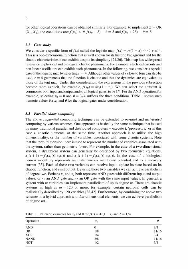
become more explicit, for example, f ðx0Þ ¼ 4x0ð12 x0Þ. We can select the constant d,common to both input and output and to all logical gates, to be 1/4. For theANDoperation, for
example, selecting x0 ¼ 0 and u ¼ 3=4 suffices the three conditions. Table 1 shows such
numeric values for x0 and u for the logical gates under consideration.
3.3 Parallel chaos computing
The above sequential computing technique can be extended to parallel and distributed
computing by various schemes. One approach is basically the same technique that is used
by many traditional parallel and distributed computers – execute L ‘processors,’ or in this
case L chaotic elements, at the same time. Another approach is to utilise the high
dimensionality, or the number of variables, associated with some chaotic systems. Note
that the term ‘dimension’ here is used to represent the number of variables associated with
the system, rather than geometric forms. For example, in the case of a two-dimensional
system, a dynamical system can generally be described by two recurrence equations,
x1ðt þ 1Þ ¼ f 1ðx1ðtÞ; x2ðtÞÞ and x2ðt þ 1Þ ¼ f 2ðx1ðtÞ; x2ðtÞÞ. In the case of a biological
neuron model, x1 represents an instantaneous membrane potential and x2 a recovery
current [35]. Each of these two variables can receive input, update its state based on its
chaotic function, and emit output. By using these two variables we can achieve parallelism
of degree two. Perhaps x1 and x2 both represent AND gates with different input and output
values, or x1 an AND gate and x2 an OR gate with the same input values. In general, a
system with m variables can implement parallelism of up to degree m. There are chaotic
systems as high as m ¼ 120 or more; for example, certain neuronal cells can be
realistically described by 120 variables [38,42]. Furthermore, by combining the above two
schemes in a hybrid approach with Lm-dimensional elements, we can achieve parallelism
of degree mL.
Table 1. Numeric examples for x0 and u for f ðxÞ ¼ 4xð12 xÞ and d ¼ 1=4.
Operation x0 u
AND 0 3/4OR 1/8 11/16XOR 1/4 3/4NAND 3/8 11/16NOT 1/2 3/4
T. Munakata et al.6
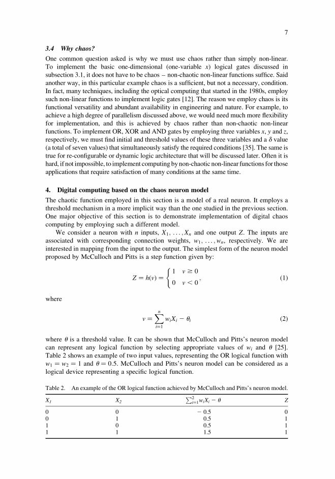
3.4 Why chaos?
One common question asked is why we must use chaos rather than simply non-linear.
To implement the basic one-dimensional (one-variable x) logical gates discussed in
subsection 3.1, it does not have to be chaos – non-chaotic non-linear functions suffice. Said
another way, in this particular example chaos is a sufficient, but not a necessary, condition.
In fact, many techniques, including the optical computing that started in the 1980s, employ
such non-linear functions to implement logic gates [12]. The reason we employ chaos is its
functional versatility and abundant availability in engineering and nature. For example, to
achieve a high degree of parallelism discussed above, we would need much more flexibility
for implementation, and this is achieved by chaos rather than non-chaotic non-linear
functions. To implement OR, XOR and AND gates by employing three variables x, y and z,
respectively, we must find initial and threshold values of these three variables and a d value
(a total of seven values) that simultaneously satisfy the required conditions [35]. The same is
true for re-configurable or dynamic logic architecture that will be discussed later. Often it is
hard, if not impossible, to implement computingbynon-chaotic non-linear functions for those
applications that require satisfaction of many conditions at the same time.
4. Digital computing based on the chaos neuron model
The chaotic function employed in this section is a model of a real neuron. It employs a
threshold mechanism in a more implicit way than the one studied in the previous section.
One major objective of this section is to demonstrate implementation of digital chaos
computing by employing such a different model.
We consider a neuron with n inputs, X1; . . . ;Xn and one output Z. The inputs are
associated with corresponding connection weights, w1; . . . ;wn, respectively. We are
interested in mapping from the input to the output. The simplest form of the neuron model
proposed by McCulloch and Pitts is a step function given by:
Z ¼ hðvÞ ¼1 v $ 0
0 v , 0
(; ð1Þ
where
v ¼Xni¼1
wiXi 2 ui ð2Þ
where u is a threshold value. It can be shown that McCulloch and Pitts’s neuron model
can represent any logical function by selecting appropriate values of wi and u [25].
Table 2 shows an example of two input values, representing the OR logical function with
w1 ¼ w2 ¼ 1 and u ¼ 0:5. McCulloch and Pitts’s neuron model can be considered as a
logical device representing a specific logical function.
Table 2. An example of the OR logical function achieved by McCulloch and Pitts’s neuron model.
X1 X2
P2i¼1wiXi 2 u Z
0 0 2 0.5 00 1 0.5 11 0 0.5 11 1 1.5 1
International Journal of Parallel, Emergent and Distributed Systems 7
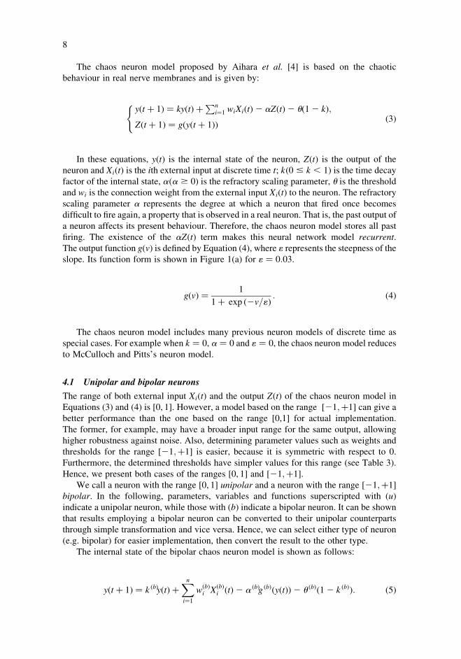
The chaos neuron model proposed by Aihara et al. [4] is based on the chaotic
behaviour in real nerve membranes and is given by:
yðt þ 1Þ ¼ kyðtÞ þPni¼1 wiXiðtÞ2 aZðtÞ2 uð12 kÞ;
Zðt þ 1Þ ¼ gðyðt þ 1ÞÞ
(ð3Þ
In these equations, yðtÞ is the internal state of the neuron, ZðtÞ is the output of the
neuron and XiðtÞ is the ith external input at discrete time t; kð0 # k , 1Þ is the time decay
factor of the internal state, aða $ 0Þ is the refractory scaling parameter, u is the thresholdand wi is the connection weight from the external input XiðtÞ to the neuron. The refractoryscaling parameter a represents the degree at which a neuron that fired once becomes
difficult to fire again, a property that is observed in a real neuron. That is, the past output of
a neuron affects its present behaviour. Therefore, the chaos neuron model stores all past
firing. The existence of the aZðtÞ term makes this neural network model recurrent.
The output function gðvÞ is defined by Equation (4), where 1 represents the steepness of theslope. Its function form is shown in Figure 1(a) for 1 ¼ 0:03.
gðvÞ ¼ 1
1þ exp ð2v=1Þ : ð4Þ
The chaos neuron model includes many previous neuron models of discrete time as
special cases. For example when k ¼ 0, a ¼ 0 and 1 ¼ 0, the chaos neuron model reduces
to McCulloch and Pitts’s neuron model.
4.1 Unipolar and bipolar neurons
The range of both external input XiðtÞ and the output ZðtÞ of the chaos neuron model in
Equations (3) and (4) is [0, 1]. However, a model based on the range ½21;þ1� can give a
better performance than the one based on the range [0,1] for actual implementation.
The former, for example, may have a broader input range for the same output, allowing
higher robustness against noise. Also, determining parameter values such as weights and
thresholds for the range ½21;þ1� is easier, because it is symmetric with respect to 0.
Furthermore, the determined thresholds have simpler values for this range (see Table 3).
Hence, we present both cases of the ranges [0, 1] and ½21;þ1�.We call a neuron with the range [0, 1] unipolar and a neuron with the range ½21;þ1�
bipolar. In the following, parameters, variables and functions superscripted with ðuÞindicate a unipolar neuron, while those with ðbÞ indicate a bipolar neuron. It can be shownthat results employing a bipolar neuron can be converted to their unipolar counterparts
through simple transformation and vice versa. Hence, we can select either type of neuron
(e.g. bipolar) for easier implementation, then convert the result to the other type.
The internal state of the bipolar chaos neuron model is shown as follows:
yðt þ 1Þ ¼ k ðbÞyðtÞ þXni¼1
wðbÞi XðbÞ
i ðtÞ2 a ðbÞg ðbÞðyðtÞÞ2 u ðbÞð12 k ðbÞÞ: ð5Þ
T. Munakata et al.8
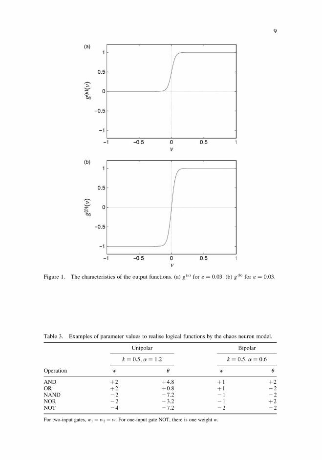
Table 3. Examples of parameter values to realise logical functions by the chaos neuron model.
Unipolar Bipolar
k ¼ 0:5; a ¼ 1:2 k ¼ 0:5; a ¼ 0:6
Operation w u w u
AND þ2 þ4.8 þ1 þ2OR þ2 þ0.8 þ1 22NAND 22 27.2 21 22NOR 22 23.2 21 þ2NOT 24 27.2 22 22
For two-input gates, w1 ¼ w2 ¼ w. For one-input gate NOT, there is one weight w.
Figure 1. The characteristics of the output functions. (a) g ðuÞ for 1 ¼ 0:03. (b) g ðbÞ for 1 ¼ 0:03.
International Journal of Parallel, Emergent and Distributed Systems 9

g ðbÞ is defined by Equation (6). Figure 1(b) shows g ðbÞ for 1 ¼ 0:03.
g ðbÞ ¼ 2
1þ exp ð2v=1Þ2 1: ð6Þ
4.2 Implementation of logical functions
We consider implementing standard logical functions by employing a unipolar neuron.
A unipolar neuron is easier to understand, but the actual implementation can be done using
a bipolar neuron as discussed in the previous subsection. For the two-input–one-output
logical functions such as AND, OR, NAND and NOR, we consider a special case of n ¼ 2,
i.e. two external inputs in Equation (3). It is sufficient to select w1 ¼ w2 ¼ w in this case.
The one-input–output logical function NOT is a special case where n ¼ 1.
We constructed the OR and NAND logical gates and numerically simulated their
dynamics. In the following, we assign parameter values k ¼ 0:5, a ¼ 1:2 and 1 ¼ 0:03 forboth OR and NAND gates. Selection of the remaining parameters u and w determines the
gate to be OR or NAND. The behaviour of the unipolar neuron for the OR gate is
shown in Figure 2(a) with parameter values w ¼ 2 and u ¼ 0:8 and initial conditions of
yð0Þ ¼ 0:001 and Zð0Þ ¼ gðyð0ÞÞ. We interpret that outputO is 0 for ZðtÞ # 0:05 andO is 1
for ZðtÞ . 0:95. Figure 2(a) is a relation between X1 þ X2 and ZðtÞ for
t ¼ 1001; . . . ; 1100, after a transient phase of t ¼ 0; . . . ; 1000. The band-like regions
(e.g. in the neighbourhoods of X1 þ X2 ¼ 0:25 and 0.75) exhibit the chaotic behaviour of
the neuron model, where ZðtÞ takes many values in terms of t. Similarly, Figure 2(b) shows
the NAND gate with w ¼ 22 and u ¼ 27:2.Implementation of standard logical functions by a bipolar neuron can be achieved
similarly. Table 3 summarises examples of parameter values that are needed to realise
various logical gates by employing unipolar and bipolar neurons. The NOT gate can be
obtained as a special case of either the NAND or NOR gate by merging the two incoming
edges into one. It is sufficient to consider only cases of X1 ¼ X2 and assign X ¼ X1.
We can select w for the NOT gate equal to 2w for the NAND or NOR gate. The table
shows parameter values using the NAND gate.
Several notes follow. In the example above, when we change the values of w1 and w2
in the OR gate from 2 to22 and change the value of u from 0:8 to27:2, it changes to theNAND gate. This is the dynamic logic architecture discussed in the previous section.
The concepts of parallel processing by a higher dimensionality of neurons and continuous
Figure 2. Behaviour of a unipolar chaos neuron (k ¼ 0:5, a ¼ 1:2, 1 ¼ 0:03). (a) the OR gate(w ¼ 2, u ¼ 0:8). (b) the NAND gate (w ¼ 22, u ¼ 27:2).
T. Munakata et al.10

logic discussed in the previous section also apply in this section. Robustness against noise
can be observed for ZðtÞ versus X1 þ X2 in Figure 2. The values of ZðtÞ in the
neighbourhood of X1 þ X2 ¼ 0; 1; 2 stay constant. Hence, small amounts, say 5%, of noise
in the input does not affect the resulting output.
5. General features of digital chaos computing
After studying the two specific approaches in the preceding sections, we are now
ready to define digital chaos computing in more general terms. Digital chaos
computing is any scheme used to implement basic computing ingredients – logical and
arithmetic functions and memory – by employing chaotic elements. Since arithmetic
functions and memory can be constructed by combining logical gates, the problem
reduces to realisation of logical gates. For example, we can implement a half adder by
combining an AND and an XOR gate. Furthermore, we can build full and higher bit
adders and flip–flop memory by combining logical operations based on integrated
circuits [7,20].
An essential point in digital chaos computing is that each input and output can
assume one of two clearly distinguishable values, corresponding to 0 and 1. For the
two-input logical gates such as AND, it is sufficient to consider a special form of
inputs as Z ¼AND ðX1 þ X2Þ. Output Z of one gate must be accepted as input X of the
next gate (cascading). The two approaches discussed in the preceding sections are
special cases, and any other form that satisfies the conditions can be digital chaos
computing.
Digital chaos computing has unique features that include the following:
Parallel computing. As discussed before for the direct threshold approach, parallel
processing of degree n can be realised by utilising n physical quantities associated with
each chaotic element.
Reconfigurable or dynamic logic architecture, where logical gates in a network can
change during computation. This is a somewhat similar idea to FPGA (Field
Programmable Gate Array) or evolvable hardware. Because of the characteristics of
chaos, we can achieve various logical gates, adders and memory by applying small
changes to the parameters on the same element. For example, consider the one-
dimensional logisticmap example discussed earlier. By selecting x0 ¼ 0 and u ¼ 3=4, wehave an AND gate; by changing them to x0 ¼ 1=8 and u ¼ 11=16 on the same chaotic
element, we can have an OR gate. Other types of gates such as XOR and NAND can be
obtained in the same fashion by slightly (all on the order of 1/16) changing these parameter
values. This is also true for the second approach, the chaos neuron model. Note that
all these conversions are made at the ‘hardware’ level on the same physical unit.
The flexibility of achieving various operation types by chaos computing leads to the new
computing architecture concept called dynamic logic architecture or evolvable dynamic
architecture.
Robustness against noise. There are three basic reasons that digital chaos computing
is robust against noise: (1) the underlying physical phenomena are deterministic;
(2) the input-to-output mappings are mostly obtained in a relatively small number of
chaotic updates, often within a few steps; (3) the physical quantities for input and
output values are based on broad ranges of values rather than single points. This is
explained in the previous section. For the direct threshold approach, a numerical
experiment is performed to demonstrate the robustness [35].
International Journal of Parallel, Emergent and Distributed Systems 11
One of the common questions asked is that why chaos computing is sensitive to small
changes, while at the same time being robust with respect to noise. The answer is it is a
matter of the degree of smallness. Our assumption is that the range of noise is smaller than
the magnitude needed for control. In Table 1, for example, to convert the AND gate to the
OR, the ratio of changes in threshold value u is 1/12 x < 8%, which is small, but not very
small. We consider a typical noise level to be smaller, which gives the rationale for
robustness. If this assumption does not hold, because either the noise level is higher or the
control ratio is smaller, this can become an issue. In most implementations, however, we
expect the assumption to hold.
A universal form of computing, i.e. a general-purpose computer for a wide spectrum of
applications.
Abundant candidates in nature and engineering.
High/low speeds, low power, simple yet cost effective.
Compared with other new computing paradigms, chaos computing can be competi-
tive in terms of speed, power consumption, cost and other characteristics. These
elements, of course, depend on a specific implementation, but there are many candidates
in nature for which these potential characteristics seem to be feasible. High speed
computing may be realised by physical/engineering devices such as chaotic lasers.
Low speed computing may be implemented in biological and micro/nano fluidic
systems. These are typically for special purposes, and not aimed at replacing conven-
tional silicon-based computers. Massively parallel processing may increase the effective
speed for biological chaos computing. In micro/nano fluidic systems, turbulence due to
ordinary convection does not occur because of low Reynolds numbers. Chaos-like
phenomena, however, due to advection [6], may be a platform of chaos computing.
Generating laser light may not require much power and may not be expensive (e.g. CD).
It does not require an extreme environment such as the very low temperature and high
magnetic fields that are required for quantum computing. Many chaotic systems are
probably less sensitive than organic or biology-oriented computing to environmental
changes such as temperature.
Chaos computing can overlap and interact with other important technical areas such
as nanotechnology.
Extensions to non-discrete computing.
We note that although we employed chaotic elements to represent ordinary logical
gates, the values involved change continuously. Hence, the methods can be extended to
represent ‘continuous’ logic such as fuzzy logic and analog computing.
6. Chaos engineering and computing
In addition to the approaches discussed in the previous sections, the direct threshold
mechanism and the chaos neuron model, there have been other chaos applications in
digital form. One major difference between these two approaches and the others is that the
first two are based on logical gates. That is, although they employ chaotic elements, the
basic principle of computing is the same as silicon-based computing. This is also true for
most other new computing paradigm techniques such as molecular and optical computing.
On the other hand, the other digital chaos computing applications are not based on logical
gates and do not perform general logical and arithmetic operations as do silicon-based
T. Munakata et al.12
computers. Rather, they manipulate digital information for specialised applications. In this
sense, the term chaos ‘computing’ can be somewhat misleading. One such example is the
encryption application [21,22], which may be considered digital chaos computing.
Quantum encryption is currently the most practical application of quantum computing.
Conventional encryption algorithms are implemented on silicon-based computers in
digital form. Other examples of digital chaos computing, in a broad sense, are applications
of the synchronisation to communications [17].
Applications of chaotic systems come in many forms. In this article, we use the
term ‘chaos engineering’ to represent engineering applications of chaotic systems in
general. Chaos engineering exploits the unique characteristics of chaotic systems to
manipulate, control or communicate a variety of systems and its practical applications
started after 1990. Chaos engineering has been applied to various engineering
problems such as control, synchronisation and communications, as well as to other
fields such as biomedicine [3,9]. Many chaos engineering applications are based on
analog systems; the remainder is digital, as cited in the above-mentioned encryption
and communications applications. Chaos computing, as discussed in this article, can
also be considered to be a special application domain of chaos engineering. Some of
the analog forms of chaos engineering can be candidates for analog chaos computing.
Physical quantities in chaotic systems are all continuous. This is also true of the digital
chaos computing discussed in the preceding sections. We can use these continuous
physical quantities in chaotic systems without digitising them. This is the basis of analog
chaos computing. For example, in a system with one input x and one output z in the direct
threshold mechanism method, we can obtain an approximate value of z by chaotic update:
x! z ¼ f ðx; tÞ, where f ðx; tÞ is a chaotic function. The analog implementation of chaotic
systems guarantees that we can obtain various desired values approximately for practical
applications [11].
Past application examples of analog based chaos engineering include: stabilisation and
control, synthesis of chaotic systems and synchronised chaos for communications and
information processing [2,3,9,11,13]. The analog aspects of these techniques may be
applied to analog chaos computing. The very basic idea is: given input values in analog
form, we compute desired output values in analog form using these chaos engineering
systems. Given a problem of a certain input-to-output mapping, we will search for a
suitable system and parameter setting. There is no guarantee of finding such a system and
parameter setting for a given problem, but considering the ergodic and fractal property of
chaotic systems in general, the chance should be high.
Analog computing has mostly been applied to special rather than general purpose
computing. This will also be true for chaos computing. For example, the three-dimensional
Lorenz equations are modeled for chaotic weather patterns. It is known that there exists a
correspondence between a coherently pumped far-infrared ammonia laser and the Lorenz
system. Analog chaos computing based on such laser systems may be applicable for
modeling weather patterns [29,35].
By combining the digital and analog schemes, we can also implement digital/analog
hybrid chaos computing systems. Such systems can perform efficient computing, utilising
the strength of each scheme. For example, analog input data may be preprocessed by the
analog part, while the intelligent computing portion is performed by the digital part.
A digital-analog hybrid system has also been implemented in hardware for large-scale
chaotic neural network simulation. This system has been applied to solve hard problems
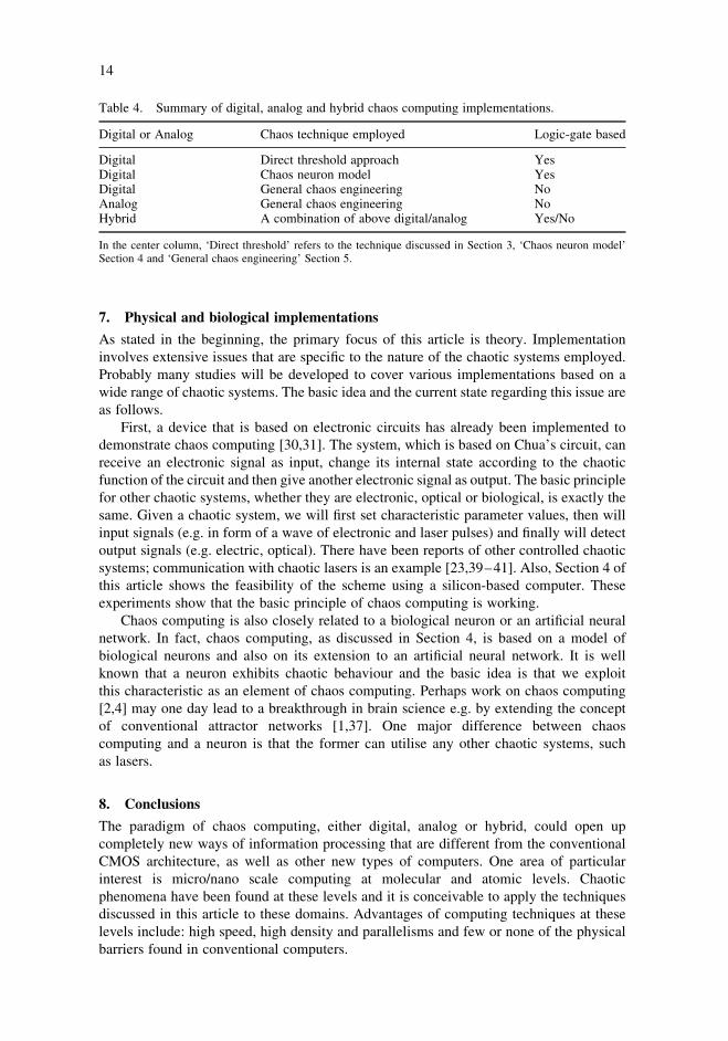
such as the quadratic assignment problem [15,16]. Table 4 summarises the computing
schemes discussed in this article.
International Journal of Parallel, Emergent and Distributed Systems 13
7. Physical and biological implementations
As stated in the beginning, the primary focus of this article is theory. Implementation
involves extensive issues that are specific to the nature of the chaotic systems employed.
Probably many studies will be developed to cover various implementations based on a
wide range of chaotic systems. The basic idea and the current state regarding this issue are
as follows.
First, a device that is based on electronic circuits has already been implemented to
demonstrate chaos computing [30,31]. The system, which is based on Chua’s circuit, can
receive an electronic signal as input, change its internal state according to the chaotic
function of the circuit and then give another electronic signal as output. The basic principle
for other chaotic systems, whether they are electronic, optical or biological, is exactly the
same. Given a chaotic system, we will first set characteristic parameter values, then will
input signals (e.g. in form of a wave of electronic and laser pulses) and finally will detect
output signals (e.g. electric, optical). There have been reports of other controlled chaotic
systems; communication with chaotic lasers is an example [23,39–41]. Also, Section 4 of
this article shows the feasibility of the scheme using a silicon-based computer. These
experiments show that the basic principle of chaos computing is working.
Chaos computing is also closely related to a biological neuron or an artificial neural
network. In fact, chaos computing, as discussed in Section 4, is based on a model of
biological neurons and also on its extension to an artificial neural network. It is well
known that a neuron exhibits chaotic behaviour and the basic idea is that we exploit
this characteristic as an element of chaos computing. Perhaps work on chaos computing
[2,4] may one day lead to a breakthrough in brain science e.g. by extending the concept
of conventional attractor networks [1,37]. One major difference between chaos
computing and a neuron is that the former can utilise any other chaotic systems, such
as lasers.
8. Conclusions
The paradigm of chaos computing, either digital, analog or hybrid, could open up
completely new ways of information processing that are different from the conventional
CMOS architecture, as well as other new types of computers. One area of particular
interest is micro/nano scale computing at molecular and atomic levels. Chaotic
phenomena have been found at these levels and it is conceivable to apply the techniques
discussed in this article to these domains. Advantages of computing techniques at these
levels include: high speed, high density and parallelisms and few or none of the physical
barriers found in conventional computers.
Table 4. Summary of digital, analog and hybrid chaos computing implementations.
Digital or Analog Chaos technique employed Logic-gate based
Digital Direct threshold approach YesDigital Chaos neuron model YesDigital General chaos engineering NoAnalog General chaos engineering NoHybrid A combination of above digital/analog Yes/No
In the center column, ‘Direct threshold’ refers to the technique discussed in Section 3, ‘Chaos neuron model’Section 4 and ‘General chaos engineering’ Section 5.
T. Munakata et al.14

Chaos computing can also be implemented in other specialised domains such as a
biological environment and micro/nano fluidics. The major objective will be to
incorporate computing functions within their application domains, enhancing the system
performance. In summary, chaos computing may lead to unique environments such as
dynamic logic architecture and parallel processing in various domains.
Acknowledgement
This research was partially supported by Grant-in-Aid for Encouragement of Scientists from MEXTof Japan (16919013).
References
[1] M. Adachi and K. Aihara, Associative dynamics in a chaotic neural network, Neural Netw.10(1) (1997), pp. 83–98.
[2] K. Aihara, Chaos engineering and its application to parallel distributed processing withchaotic neural networks, Proc. IEEE 90(5) (2002), pp. 919–930.
[3] K. Aihara and R. Katayama, Chaos engineering in Japan, Comm. ACM 38(11) (1995),pp. 103–107.
[4] K. Aihara, T. Takabe, and M. Toyoda, Chaotic neural networks, Phys. Lett. A 144(6/7) (1990),pp. 333–340.
[5] M. Aono, M. Hara, and K. Aihara, Amoeba-based neurocomputing with chaotic dynamics,Comm. ACM 50(9) (2007), pp. 69–72.
[6] H. Aref, Fluid dynamics: order in chaos, Nature 401(6755) (1999), pp. 756–758.[7] T.C. Bartee, Computer Architecture and Logic Design, McGraw-Hill College, New York,
1991.[8] D. Cafagna and G. Grassi, Chaos-based SR flip–flop via chua’s circuit, Int. J. Bifurc. Chaos
16(5) (2006), pp. 1521–1526.[9] W.L. Ditto and T. Munakata, Principles and applications of chaotic systems, Comm. ACM
38(11) (1995), pp. 96–102.[10] W.L. Ditto and L.M. Pecora, Mastering chaos, Sci. Am. 269(2) (1993), pp. 78–84.[11] Y. Dote and S.J. Ovaska, Industrial applications of soft computing: a review, Proc. IEEE 89(9)
(2001), pp. 1243–1265.[12] Y. Horio, K. Aihara, and O. Yamamoto, Neuron-synapse IC chip-set for large-scale chaotic
neural networks, IEEE Trans. Neural Netw. 14(5) (2003), pp. 1393–1404.[13] D.G. Feitelson, Optical Computing, MIT Press, Cambridge, MA, 1988.[14] S. Hayes, C. Grebogi, E. Ott, and A. Mark, Experimental control of chaos for communication,
Phys. Rev. Lett. 73(13) (1994), pp. 1781–1784.[15] M. Hasler et al., ed. Special issue on applications of nonlinear dynamics to electronic and
information engineering, Proc. IEEE 90(5) (2002).[16] Y. Horio, T. Ikeguchi, and K. Aihara, A mixed analog/digital chaotic neuro-computer system
for quadratic assignment problems, Neural Netw. 18(5/6) (2005), pp. 505–513.[17] G. Kolumban, M.P. Kennedy, and L.O. Chua, The role of synchronization in digital
communications using chaos. Part I: fundamentals of digital communications, IEEE Trans.Circuits Syst. I 44(10) (1997), pp. 927–936.
[18] X. Leyronas, P.G. Silvestrov, and C.W.J. Beenakker, Scaling at the chaos threshold forinteracting electrons in a quantum dot, Phys. Rev. Lett. 84(15) (2000), pp. 3414–3417.
[19] J.C. Lorquet, Landmarks in the theory of mass spectra, Int. J. Mass Spectrom. 200(1) (2000),pp. 43–56.
[20] M.M. Mano, Computer System Architecture, 3rd ed., Prentice Hall, Englewood Cliffs, NJ,1992.
[21] N. Masuda and K. Aihara, Cryptosystems with discretized chaotic maps, IEEE Trans. CircuitsSyst. I 49(1) (2002), pp. 28–40.
[22] N. Masuda, G. Jakimoski, K. Aihara, and L. Kocarev, Chaotic block ciphers: from theory topractical algorithms, IEEE Trans. Circuits Syst. I 53(6) (2006), pp. 1341–1352.
[23] T. Matsuura, A. Uchida, and S. Yohimori, Chaotic wavelength division multiplexing for opticalcommunication, Optics Lett. 29(23) (2004), pp. 2731–2733.
International Journal of Parallel, Emergent and Distributed Systems 15

[24] R.M. May, Simple mathematical models with very complicated dynamics, Nature 261(5560)(1976), pp. 459–467.
[25] W.S. McCulloch and W.H. Pitts, A logical calculus of the ideas immanent in neural nets,Bull. Math. Biophys. 5(4) (1943), pp. 115–133.
[26] T. Munakata, Fundamentals of the New Artificial Intelligence: Neural, Evolutionary, Fuzzy andMore, Chap. 7, Springer, London, 2008.
[27] T. Munakata and S. Sinha, Implementation of fundamental logical gates by 1-D chaoticelements, in Proceedings of COOL Chips VI. Yokohama, 16–18 April 2003, p. 73.
[28] T. Munakata (ed.), Special section, beyond silicon: new computing paradigms, Comm. ACM50(9) (2007), pp. 30–72.
[29] T. Munakata, S. Sinha, and W.L. Ditto, Chaos computing: implementation of fundamentallogical gates by chaotic elements, IEEE Trans. Circuits Syst. I 49(11) (2002), pp. 1629–1633.
[30] K. Murali, S. Sinha, and W.L. Ditto, Implementation of NOR gate by a chaotic Chua’s circuit,Int. J. Bifurcation Chaos 13(9) (2003), pp. 2669–2672.
[31] K. Murali, S. Sinha, and W.L. Ditto, Realization of the fundamental NOR gate using a chaoticcircuit, Phys. Rev. E 68(1) (2003), 016205.
[32] L.M. Pecora and T.L. Caroll, Driving systems with chaotic signals, Phys. Rev. A 44(4) (1991),pp. 2374–2383.
[33] T. Shinbrot, C. Grebogi, E. Ott, and J.A. Yorke, Using small perturbations to control chaos,Nature 363(6428) (1993), pp. 411–417.
[34] S. Sinha and W.L. Ditto, Dynamics based computation, Phys. Rev. Lett. 81(10) (1998),pp. 2156–2159.
[35] S. Sinha, T. Munakata, and W.L. Ditto, Flexible parallel implementation of logic gates usingchaotic elements, Phys. Rev. E 65(3) (2002), 036216.
[36] S. Sinha, T. Munakata, and W.L. Ditto, Parallel computing with extended dynamical systems,Phys. Rev. E 65(3) (2002), 036214.
[37] C.A. Skarda and W.J. Freeman, How brains make chaos in order to make sense of the world,Behav. Brain Sci. 10(2) (1987), pp. 161–195.
[38] R.D. Traub and R. Miles, Neuronal Networks of the Hippocampus, Cambridge UniversityPress, New York, 1991.
[39] A. Uchida and S. Yoshimori, Synchronization of chaos in microchip lasers and itscommunication applications, C.R. Phys. 5(6) (2004), pp. 643–656.
[40] A. Uchida, F. Rogister, J. Garcia-Ojalvo, and R. Roy, Synchronization and communication withchaotic laser systems, in Progress in Optics, vol. 48, E. Wolf, ed., Elsevier, The Netherlands,2005, pp. 203–341.
[41] G.D. Van Wiggeren and R. Roy, Communications with chaotic lasers, Science 279(5354)(1998), pp. 1198–1200.
[42] B.J. West (ed.), Patterns, Information and Chaos in Neuronal Systems, World ScientificPublishing, Singapore, 1993, and references therein.
T. Munakata et al.16