Channels and Maximum Power Settings for Cisco Aironet ... · Contents iv Channels and Maximum Power...
130
Americas Headquarters Cisco Systems, Inc. 170 West Tasman Drive San Jose, CA 95134-1706 USA http://www.cisco.com Tel: 408 526-4000 800 553-NETS (6387) Fax: 408 527-0883 Channels and Maximum Power Settings for Cisco Aironet Lightweight Access Points October, 2008 Text Part Number: OL-11321-08
Transcript of Channels and Maximum Power Settings for Cisco Aironet ... · Contents iv Channels and Maximum Power...
Channels and Maximum Power Settings for Cisco Aironet Lightweight Access PointsOctober, 2008
Americas HeadquartersCisco Systems, Inc.170 West Tasman DriveSan Jose, CA 95134-1706 USAhttp://www.cisco.comTel: 408 526-4000
800 553-NETS (6387)Fax: 408 527-0883
Text Part Number: OL-11321-08
THE SPECIFICATIONS AND INFORMATION REGARDING THE PRODUCTS IN THIS MANUAL ARE SUBJECT TO CHANGE WITHOUT NOTICE. ALL STATEMENTS, INFORMATION, AND RECOMMENDATIONS IN THIS MANUAL ARE BELIEVED TO BE ACCURATE BUT ARE PRESENTED WITHOUT WARRANTY OF ANY KIND, EXPRESS OR IMPLIED. USERS MUST TAKE FULL RESPONSIBILITY FOR THEIR APPLICATION OF ANY PRODUCTS.
THE SOFTWARE LICENSE AND LIMITED WARRANTY FOR THE ACCOMPANYING PRODUCT ARE SET FORTH IN THE INFORMATION PACKET THAT SHIPPED WITH THE PRODUCT AND ARE INCORPORATED HEREIN BY THIS REFERENCE. IF YOU ARE UNABLE TO LOCATE THE SOFTWARE LICENSE OR LIMITED WARRANTY, CONTACT YOUR CISCO REPRESENTATIVE FOR A COPY.
The following information is for FCC compliance of Class A devices: This equipment has been tested and found to comply with the limits for a Class A digital device, pursuant to part 15 of the FCC rules. These limits are designed to provide reasonable protection against harmful interference when the equipment is operated in a commercial environment. This equipment generates, uses, and can radiate radio-frequency energy and, if not installed and used in accordance with the instruction manual, may cause harmful interference to radio communications. Operation of this equipment in a residential area is likely to cause harmful interference, in which case users will be required to correct the interference at their own expense.
The following information is for FCC compliance of Class B devices: The equipment described in this manual generates and may radiate radio-frequency energy. If it is not installed in accordance with Cisco’s installation instructions, it may cause interference with radio and television reception. This equipment has been tested and found to comply with the limits for a Class B digital device in accordance with the specifications in part 15 of the FCC rules. These specifications are designed to provide reasonable protection against such interference in a residential installation. However, there is no guarantee that interference will not occur in a particular installation.
Modifying the equipment without Cisco’s written authorization may result in the equipment no longer complying with FCC requirements for Class A or Class B digital devices. In that event, your right to use the equipment may be limited by FCC regulations, and you may be required to correct any interference to radio or television communications at your own expense.
You can determine whether your equipment is causing interference by turning it off. If the interference stops, it was probably caused by the Cisco equipment or one of its peripheral devices. If the equipment causes interference to radio or television reception, try to correct the interference by using one or more of the following measures:
• Turn the television or radio antenna until the interference stops.
• Move the equipment to one side or the other of the television or radio.
• Move the equipment farther away from the television or radio.
• Plug the equipment into an outlet that is on a different circuit from the television or radio. (That is, make certain the equipment and the television or radio are on circuits controlled by different circuit breakers or fuses.)
Modifications to this product not authorized by Cisco Systems, Inc. could void the FCC approval and negate your authority to operate the product.
The Cisco implementation of TCP header compression is an adaptation of a program developed by the University of California, Berkeley (UCB) as part of UCB’s public domain version of the UNIX operating system. All rights reserved. Copyright © 1981, Regents of the University of California.
NOTWITHSTANDING ANY OTHER WARRANTY HEREIN, ALL DOCUMENT FILES AND SOFTWARE OF THESE SUPPLIERS ARE PROVIDED “AS IS” WITH ALL FAULTS. CISCO AND THE ABOVE-NAMED SUPPLIERS DISCLAIM ALL WARRANTIES, EXPRESSED OR IMPLIED, INCLUDING, WITHOUT LIMITATION, THOSE OF MERCHANTABILITY, FITNESS FOR A PARTICULAR PURPOSE AND NONINFRINGEMENT OR ARISING FROM A COURSE OF DEALING, USAGE, OR TRADE PRACTICE.
IN NO EVENT SHALL CISCO OR ITS SUPPLIERS BE LIABLE FOR ANY INDIRECT, SPECIAL, CONSEQUENTIAL, OR INCIDENTAL DAMAGES, INCLUDING, WITHOUT LIMITATION, LOST PROFITS OR LOSS OR DAMAGE TO DATA ARISING OUT OF THE USE OR INABILITY TO USE THIS MANUAL, EVEN IF CISCO OR ITS SUPPLIERS HAVE BEEN ADVISED OF THE POSSIBILITY OF SUCH DAMAGES.
Cisco and the Cisco Logo are trademarks of Cisco Systems, Inc. and/or its affiliates in the U.S. and other countries. A listing of Cisco's trademarks can be found at www.cisco.com/go/trademarks. Third party trademarks mentioned are the property of their respective owners. The use of the word partner does not imply a partnership relationship between Cisco and any other company. (1005R)
Channels and Maximum Power Settings for Cisco Aironet Lightweight Access Points©2011 Cisco Systems, Inc. All rights reserved.

ChanOL-11321-08
C O N T E N T S
Preface vii
Audience i-vii
Purpose i-vii
Organization i-viii
Conventions i-viii
Related Publications i-ix
Obtaining Documentation, Obtaining Support, and Security Guidelines i-ix
C H A P T E R 1 Cisco Aironet 1000 Series Access Points 1-1
Channels and Maximum Power Levels 1-2
IEEE 802.11b/g (2.4-GHz Band) 1-2
IEEE 802.11a (5-GHz Band) 1-3
Special Country Restrictions 1-6
Changing the Lightweight Access Point Output Power 1-6
C H A P T E R 2 Cisco Aironet 1100 Series Access Points 2-9
Channels 2-10
AIR-LAP1121G IEEE 802.11g (2.4-GHz Band) 2-10
Maximum Power Levels 2-11
IEEE 802.11b (2.4-GHz Band) 2-11
IEEE 802.11g (2.4-GHz Band) 2-11
Changing the Lightweight Access Point Output Power 2-12
C H A P T E R 3 Cisco Aironet 1130 Series Access Points 3-1
IEEE 802.11b/g (2.4-GHz Band) 3-2
Channels and Maximum Power Levels 3-3
IEEE 802.11b/g (2.4-GHz Band) 3-3
IEEE 802.11a (5-GHz Band) 3-3
Special Country Restrictions 3-5
Changing the Lightweight Access Point Output Power 3-5
iiinels and Maximum Power Settings for Cisco Aironet Lightweight Access Points
Contents
C H A P T E R 4 Cisco Aironet 1140 Series Lightweight Access Points 4-1
Channels and Maximum Power Levels 4-2
2.4 GHz Band (Draft IEEE 802.11n Version 2.0) 4-3
5 GHz Band (Draft IEEE 802.11n Version 2.0) 4-9
Special Country Restrictions 4-19
Changing Lightweight Access Point Output Power 4-19
C H A P T E R 5 Cisco Aironet 1200 Series Access Points 5-1
Channels 5-2
IEEE 802.11g (2.4-GHz Band) 5-2
IEEE 802.11a (5-GHz Band) 5-2
Maximum Power Levels and Antenna Gains 5-4
IEEE 802.11g (2.4-GHz Band) 5-4
IEEE 802.11a (5-GHz Band) 5-5
Maximum Power Levels in Some Regulatory Domains with External Antennas 5-8
Special Country Restrictions 5-9
Power Conversion Table 5-9
Changing the Lightweight Access Point Output Power 5-10
C H A P T E R 6 Cisco Aironet 1240 Series Access Points 6-1
Channels and Maximum Power Levels 6-2
IEEE 802.11g (2.4-GHz Band) 6-2
IEEE 802.11g (2.4-GHz Band) 6-3
IEEE 802.11a (5-GHz Band) 6-4
Maximum Power Levels in Some Regulatory Domains with External Antennas 6-5
Special Country Restrictions 6-7
Changing the Lightweight Access Point Output Power 6-7
C H A P T E R 7 Cisco Aironet 1250 Series Lightweight Access Points 7-1
Channels and Maximum Power Levels 7-2
2.4 GHz Band (Draft IEEE 802.11n Version 2.0) 7-2
5 GHz Band (Draft IEEE 802.11n Version 2.0) 7-8
Special Country Restrictions 7-18
Changing Lightweight Access Point Output Power 7-18
ivChannels and Maximum Power Settings for Cisco Aironet Lightweight Access Points
OL-11321-08
Contents
C H A P T E R 8 Cisco Aironet 1300 Series Access Points 8-1
Channels 8-2
IEEE 802.11g (2.4-GHz Band) 8-2
Maximum Power Levels and Antenna Gains 8-3
IEEE 802.11b/g (2.4-GHz Band) 8-3
Changing the Lightweight Access Point Output Power 8-4
Power Conversion Table 8-6
C H A P T E R 9 Cisco Aironet 1500 Series Mesh Access Points 9-1
Channels and Maximum Power Levels 9-2
IEEE 802.11b/g (2.4-GHz Band) 9-2
IEEE 802.11a (5-GHz Band) 9-3
Antenna Settings 9-5
Maximum Power Levels Allowed in Some Regulatory Domains 9-5
Special Country Restrictions 9-7
Changing the Lightweight Access Point Output Power 9-8
C H A P T E R 10 Cisco Aironet 1520 Series Mesh Access Points 10-1
Channels and Maximum Power Levels 10-2
AIR-LAP1521G 10-2
IEEE 802.11b/g (2.4-GHz Band) 10-2
AIR-LAP1522AG 10-4
IEEE 802.11b/g (2.4-GHz Band) 10-4
IEEE 802.11a (5-GHz Band) 10-5
Minimum 5-GHz Radio Power Levels 10-12
Special Country Restrictions 10-13
AIR-LAP1524AG and 4.9-GHz Public Safety Models 10-14
IEEE 802.11b/g (2.4-GHz Band) 10-14
4.9-GHz Public Safety Band 10-15
IEEE 802.11a (5-GHz Band) 10-16
Changing the Lightweight Access Point Output Power 10-17
vChannels and Maximum Power Settings for Cisco Aironet Lightweight Access Points
OL-11321-08
Contents
viChannels and Maximum Power Settings for Cisco Aironet Lightweight Access Points
OL-11321-08
Preface
AudienceThis guide is for the networking professional who installs and manages Cisco Aironet access points and bridges.
To use this guide with lightweight access points, you should have experience working with a Cisco Wireless LAN Controller and be familiar with the concepts and terminology of wireless local area networks.
PurposeThis guide provides the channel and maximum power settings you need to install your lightweight access points and bridges in supported regulatory regions.
For hardware information about Cisco Aironet access points and bridges, refer to the product hardware installation guides for your access points and bridges available from the Cisco.com at this URL:
http://www.cisco.com/en/US/products/hw/wireless/
The access point products are listed under the “Access Points” and “Outdoor Wireless” sections. Choose the needed product, then click Install and Upgrade in the Support box.
For information about Cisco Wireless LAN Controllers, refer to the Cisco documentation sets available under the “Wireless LAN Controllers” section. Choose the needed controller, then click on the documentation type in the Support box.
viiChannels and Maximum Power Settings for Cisco Aironet Lightweight Access Points
OL-11321-08
Preface Organization
OrganizationThis guide is organized into these chapters:
Chapter 1, “Cisco Aironet 1000 Series Access Points,” lists the 1000 series lightweight access point radio channels and the maximum power levels supported by the world’s regulatory domains.
Chapter 2, “Cisco Aironet 1100 Series Access Points,” lists the 1100 series lightweight access point radio channels and the maximum power levels supported by the world’s regulatory domains.
Chapter 3, “Cisco Aironet 1130 Series Access Points,” lists the 1130 series lightweight access point radio channels and the maximum power levels supported by the world’s regulatory domains.
Chapter 4, “Cisco Aironet 1040 and 1140 Series Lightweight Access Points”, lists the 1140 series lightweight access point radio channels and maximum power levels supported by the world’s regulatory domains.
Chapter 5, “Cisco Aironet 1200 Series Access Points,” lists the 1200 series lightweight access point radio channels and the maximum power levels supported by the world’s regulatory domains.
Chapter 6, “Cisco Aironet 1240 Series Access Points,” lists the 1240 series lightweight access point radio channels and the maximum power levels supported by the world’s regulatory domains.
Chapter 7, “Cisco Aironet 1250 Series Lightweight Access Points,” lists the 1250 series lightweight access point radio channels and the maximum power levels supported by the world’s regulatory domains.
Chapter 8, “Cisco Aironet 1300 Series Access Points,” lists the 1300 series lightweight outdoor access point/bridge radio channels and the maximum power levels supported by the world’s regulatory domains.
Chapter 9, “Cisco Aironet 1500 Series Mesh Access Points,” lists the 1500 series lightweight outdoor mesh access point radio channels and the maximum power levels supported by the world’s regulatory domains.
Chapter 10, “Cisco Aironet 1520 Series Mesh Access Points,” lists the 1520 series lightweight outdoor mesh access point radio channels and the maximum power levels supported by the world’s regulatory domains.
ConventionsThis publication uses these conventions to convey instructions and information:
Interactive examples use these conventions:
• Terminal sessions and system displays are in screen font.
• Information you enter is in boldface screen font.
• Nonprinting characters, such as passwords or tabs, are in angle brackets (< >).
Notes, cautions, and timesavers use these conventions and symbols:
Tip Means the following will help you solve a problem. The tips information might not be troubleshooting or even an action, but could be useful information.
Note Means reader take note. Notes contain helpful suggestions or references to materials not contained in this manual.
viiiChannels and Maximum Power Settings for Cisco Aironet Lightweight Access Points
OL-11321-08
Preface Related Publications
Caution Means reader be careful. In this situation, you might do something that could result equipment damage or loss of data.
Related PublicationsThese documents provide information about the access points and bridges:
• Cisco Aironet 1000 Series Lightweight Access Point Hardware Installation Guide
• Cisco Aironet 1100 Series Access Point Hardware Installation Guide
• Cisco Aironet 1130AG Series Access Point Hardware Installation Guide
• Cisco Aironet 1140 Series Lightweight Access Point Getting Started Guide
• Cisco Aironet 1200 Series Access Point Hardware Installation Guide
• Cisco Aironet 1240AG Series Access Point Hardware Installation Guide
• Cisco Aironet 1250 Series Access Point Hardware Installation Guide
• Cisco Aironet 1300 Series Access Point/Bridge Hardware Installation Guide
• Cisco Aironet 1500 Series Outdoor Mesh Access Point Hardware Installation Guide
• Cisco Aironet 1520 Series Outdoor Mesh Access Point Hardware Installation Guide
• Cisco IOS Software Configuration Guide for Cisco Aironet Access Points
• Cisco Wireless LAN Controller Configuration Guide
Click this link to browse to the Cisco Wireless documentation home page:
http://www.cisco.com/en/US/products/hw/wireless/
To browse to the access point and bridge documentation, scroll down to the Product Portfolio section and select a product. The documentation is available from the Support box.
To browse to the Cisco Wireless LAN Controller documentation, click Cisco 4400 Series Wireless LAN Controllers or Cisco 2100 Series Wireless LAN Controllers listed in the “Standalone Controllers” section under “Wireless LAN Controllers.” The documentation is available from the Support box.
Obtaining Documentation, Obtaining Support, and Security Guidelines
For information on obtaining documentation, obtaining support, providing documentation feedback, security guidelines, and also recommended aliases and general Cisco documents, see the monthly What’s New in Cisco Product Documentation, which also lists all new and revised Cisco technical documentation, at:
http://www.cisco.com/en/US/docs/general/whatsnew/whatsnew.html
ixChannels and Maximum Power Settings for Cisco Aironet Lightweight Access Points
OL-11321-08
Preface Obtaining Documentation, Obtaining Support, and Security Guidelines
xChannels and Maximum Power Settings for Cisco Aironet Lightweight Access Points
OL-11321-08
Channels and Maximum Power SeOL-11321-08
C H A P T E R 1
Cisco Aironet 1000 Series Access PointsThis chapter lists the IEEE 802.11b/g (2.4-GHz) and the IEEE 802.11a (5-GHz) channels and maximum power levels supported by the world’s regulatory domains for the Cisco Aironet 1000 Series Lightweight Access Point. For additional product hardware information refer to the Cisco Aironet 1000 Series Lightweight Access Point Hardware Installation Guide.
The following topic is covered in this appendix:
• Channels and Maximum Power Levels, page 1-2
1-1ttings for Cisco Aironet Lightweight Access Points
Chapter 1 Cisco Aironet 1000 Series Access Points Channels and Maximum Power Levels
Channels and Maximum Power Levels
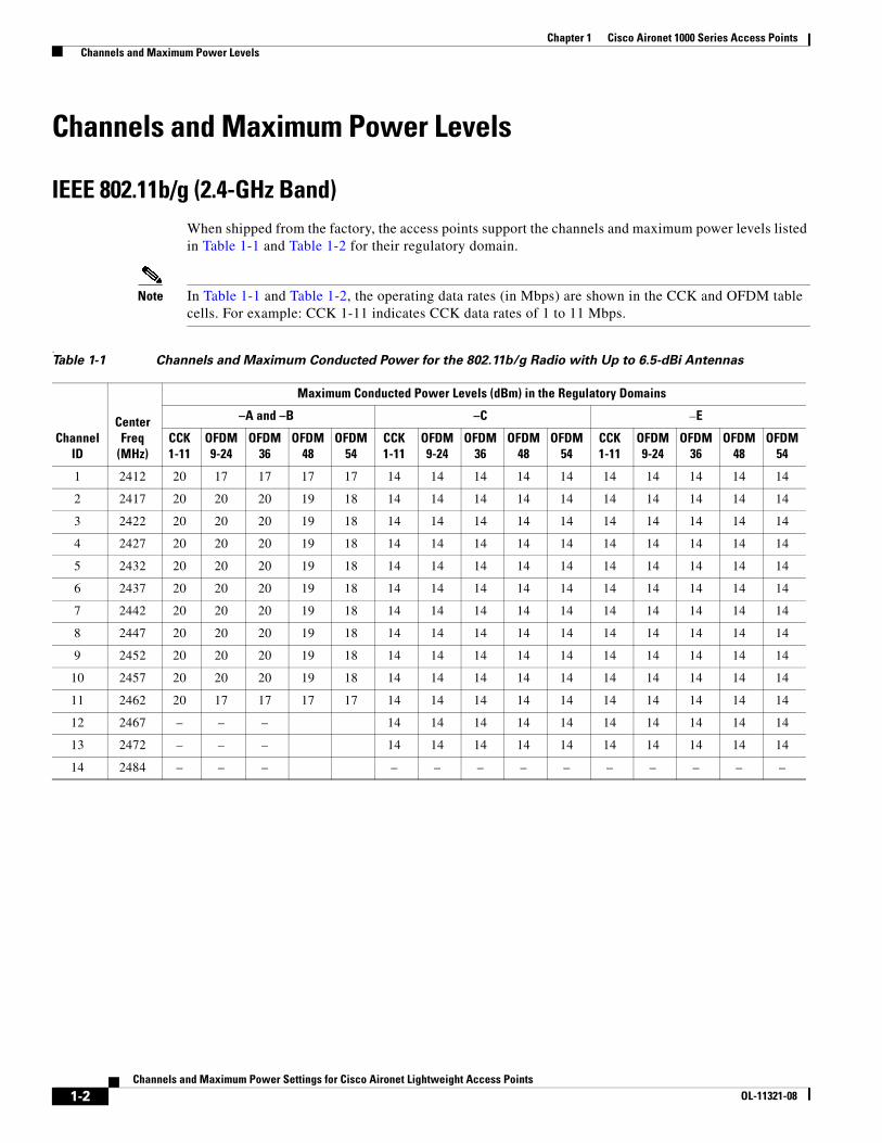
IEEE 802.11b/g (2.4-GHz Band)When shipped from the factory, the access points support the channels and maximum power levels listed in Table 1-1 and Table 1-2 for their regulatory domain.
Note In Table 1-1 and Table 1-2, the operating data rates (in Mbps) are shown in the CCK and OFDM table cells. For example: CCK 1-11 indicates CCK data rates of 1 to 11 Mbps.
.Table 1-1 Channels and Maximum Conducted Power for the 802.11b/g Radio with Up to 6.5-dBi Antennas
Channel ID
Center Freq
(MHz)
Maximum Conducted Power Levels (dBm) in the Regulatory Domains
–A and –B –C –E
CCK1-11
OFDM9-24
OFDM36
OFDM48
OFDM54
CCK1-11
OFDM9-24
OFDM36
OFDM48
OFDM54
CCK1-11
OFDM9-24
OFDM36
OFDM48
OFDM54
1 2412 20 17 17 17 17 14 14 14 14 14 14 14 14 14 14
2 2417 20 20 20 19 18 14 14 14 14 14 14 14 14 14 14
3 2422 20 20 20 19 18 14 14 14 14 14 14 14 14 14 14
4 2427 20 20 20 19 18 14 14 14 14 14 14 14 14 14 14
5 2432 20 20 20 19 18 14 14 14 14 14 14 14 14 14 14
6 2437 20 20 20 19 18 14 14 14 14 14 14 14 14 14 14
7 2442 20 20 20 19 18 14 14 14 14 14 14 14 14 14 14
8 2447 20 20 20 19 18 14 14 14 14 14 14 14 14 14 14
9 2452 20 20 20 19 18 14 14 14 14 14 14 14 14 14 14
10 2457 20 20 20 19 18 14 14 14 14 14 14 14 14 14 14
11 2462 20 17 17 17 17 14 14 14 14 14 14 14 14 14 14
12 2467 – – – 14 14 14 14 14 14 14 14 14 14
13 2472 – – – 14 14 14 14 14 14 14 14 14 14
14 2484 – – – – – – – – – – – – –
1-2Channels and Maximum Power Settings for Cisco Aironet Lightweight Access Points
OL-11321-08
Chapter 1 Cisco Aironet 1000 Series Access Points Channels and Maximum Power Levels
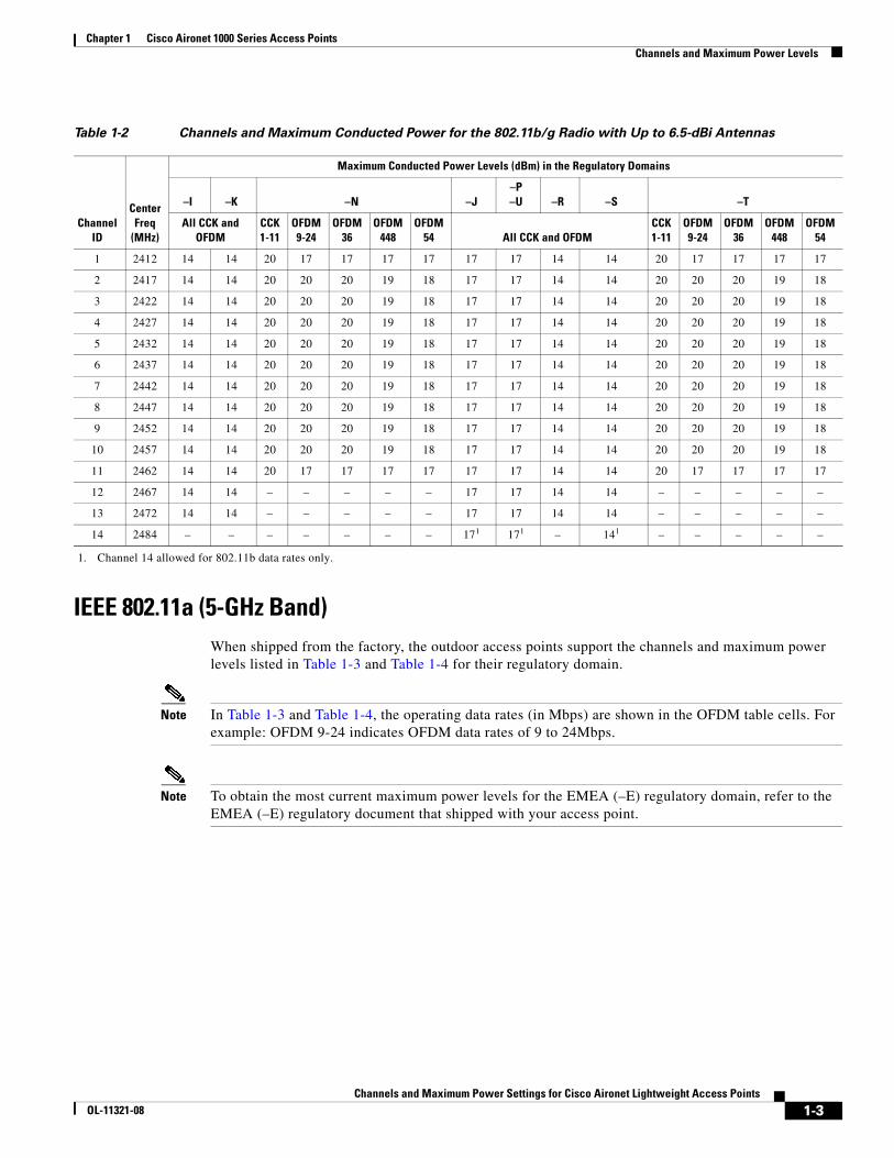
IEEE 802.11a (5-GHz Band)When shipped from the factory, the outdoor access points support the channels and maximum power levels listed in Table 1-3 and Table 1-4 for their regulatory domain.
Note In Table 1-3 and Table 1-4, the operating data rates (in Mbps) are shown in the OFDM table cells. For example: OFDM 9-24 indicates OFDM data rates of 9 to 24Mbps.
Note To obtain the most current maximum power levels for the EMEA (–E) regulatory domain, refer to the EMEA (–E) regulatory document that shipped with your access point.
Table 1-2 Channels and Maximum Conducted Power for the 802.11b/g Radio with Up to 6.5-dBi Antennas
Maximum Conducted Power Levels (dBm) in the Regulatory Domains
Channel ID
Center Freq
(MHz)
–I –K –N –J–P–U –R –S –T
All CCK and OFDM
CCK1-11
OFDM9-24
OFDM36
OFDM448
OFDM54 All CCK and OFDM
CCK1-11
OFDM9-24
OFDM36
OFDM448
OFDM54
1 2412 14 14 20 17 17 17 17 17 17 14 14 20 17 17 17 17
2 2417 14 14 20 20 20 19 18 17 17 14 14 20 20 20 19 18
3 2422 14 14 20 20 20 19 18 17 17 14 14 20 20 20 19 18
4 2427 14 14 20 20 20 19 18 17 17 14 14 20 20 20 19 18
5 2432 14 14 20 20 20 19 18 17 17 14 14 20 20 20 19 18
6 2437 14 14 20 20 20 19 18 17 17 14 14 20 20 20 19 18
7 2442 14 14 20 20 20 19 18 17 17 14 14 20 20 20 19 18
8 2447 14 14 20 20 20 19 18 17 17 14 14 20 20 20 19 18
9 2452 14 14 20 20 20 19 18 17 17 14 14 20 20 20 19 18
10 2457 14 14 20 20 20 19 18 17 17 14 14 20 20 20 19 18
11 2462 14 14 20 17 17 17 17 17 17 14 14 20 17 17 17 17
12 2467 14 14 – – – – – 17 17 14 14 – – – – –
13 2472 14 14 – – – – – 17 17 14 14 – – – – –
14 2484 – – – – – – – 171
1. Channel 14 allowed for 802.11b data rates only.
171 – 141 – – – – –
1-3Channels and Maximum Power Settings for Cisco Aironet Lightweight Access Points
OL-11321-08
Chapter 1 Cisco Aironet 1000 Series Access Points Channels and Maximum Power Levels
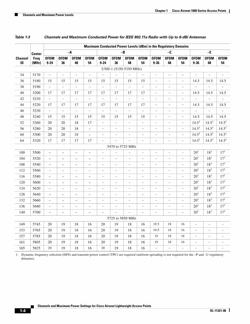
, Table 1-3 Channels and Maximum Conducted Power for IEEE 802.11a Radio with Up to 6-dBi Antennas
ChannelID
Center Freq
(MHz)
Maximum Conducted Power Levels (dBm) in the Regulatory Domains
–A –B –C –E
OFDM9-24
OFDM36
OFDM48
OFDM54
OFDM9-24
OFDM36
OFDM48
OFDM54
OFDM9-36
OFDM48
OFDM54
OFDM9-36
OFDM48
OFDM54
UNII-1 (5150-5350 MHz)
34 5170 – – – – – – – – – – – – – –
36 5180 15 15 15 15 15 15 15 15 – – – 14.5 14.5 14.5
38 5190 – – – – – – – – – – – – – –
40 5200 17 17 17 17 17 17 17 17 – – – 14.5 14.5 14.5
42 5210 – – – – – – – – – – – – – –
44 5220 17 17 17 17 17 17 17 17 – – – 14.5 14.5 14.5
46 5230 – – – – – – – – – – – – – –
48 5240 15 15 15 15 15 15 15 15 – – – 14.5 14.5 14.5
52 5260 20 20 18 17 – – – – – – – 14.51
1. Dynamic frequency selection (DFS) and transmit power control (TPC) are required (uniform spreading is not required for the –P and –U regulatory domains).
14.51 14.51
56 5280 20 20 18 – – – – – – – – 14.51 14.51 14.51
60 5300 20 20 18 – – – – – – – – 14.51 14.51 14.51
64 5320 17 17 17 17 – – – – – – – 14.51 14.51 14.51
5470 to 5725 MHz
100 5500 – – – – – – – – – – – 201 181 171
104 5520 – – – – – – – – – – – 201 181 171
108 5540 – – – – – – – – – – – 201 181 171
112 5560 – – – – – – – – – – – 201 181 171
116 5580 – – – – – – – – – – – 201 181 171
120 5600 – – – – – – – – – – – 201 181 171
124 5620 – – – – – – – – – – – 201 181 171
128 5640 – – – – – – – – – – – 201 181 171
132 5660 – – – – – – – – – – – 201 181 171
136 5680 – – – – – – – – – – – 201 181 171
140 5700 – – – – – – – – – – – 201 181 171
5725 to 5850 MHz
149 5745 20 19 18 16 20 19 18 16 19.5 18 16 – – –
153 5765 20 19 18 16 20 19 18 16 19.5 18 16 – – –
157 5785 20 19 18 16 20 19 18 16 19 18 16 – – –
161 5805 20 19 18 16 20 19 18 16 19 18 16 – – –
165 5825 20 19 18 16 20 19 18 16 – – – – – –
1-4Channels and Maximum Power Settings for Cisco Aironet Lightweight Access Points
OL-11321-08
Chapter 1 Cisco Aironet 1000 Series Access Points Channels and Maximum Power Levels
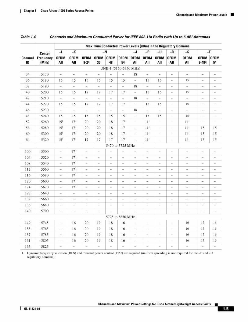
Table 1-4 Channels and Maximum Conducted Power for IEEE 802.11a Radio with Up to 6-dBi Antennas
ChannelID
Center Frequency
(MHz)
Maximum Conducted Power Levels (dBm) in the Regulatory Domains
–I –K –N –J –P –U –R –S –T
OFDMAll
OFDMAll
OFDM9-24
OFDM36
OFDM48
OFDM54
OFDMAll
OFDMAll
OFDMAll
OFDMAll
OFDMAll
OFDM9-484
OFDM54
UNII-1 (5150-5350 MHz)
34 5170 – – – – – – 18 – – – – – –
36 5180 15 15 15 15 15 15 – 15 15 – 15 – –
38 5190 – – – – – – 18 – – – – – –
40 5200 15 15 17 17 17 17 – 15 15 – 15 – –
42 5210 – – – – – – 18 – – – – – –
44 5220 15 15 17 17 17 17 – 15 15 – 15 – –
46 5230 – – – – – – 18 – – – – – –
48 5240 15 15 15 15 15 15 – 15 15 – 15 – –
52 5260 151 171 20 20 18 17 – 111
1. Dynamic frequency selection (DFS) and transmit power control (TPC) are required (uniform spreading is not required for the –P and –U regulatory domains).
– – 141 – –
56 5280 151 171 20 20 18 17 – 111 – – 141 15 15
60 5300 151 171 20 20 18 17 – 111 – – 141 15 15
64 5320 151 171 17 17 17 17 – 111 – – 141 15 15
5470 to 5725 MHz
100 5500 – 171 – – – – – – – – – – –
104 5520 – 171 – – – – – – – – – – –
108 5540 – 171 – – – – – – – – – – –
112 5560 – 171 – – – – – – – – – – –
116 5580 – 171 – – – – – – – – – – –
120 5600 – 171 – – – – – – – – – – –
124 5620 – 171 – – – – – – – – – – –
128 5640 – – – – – – – – – – – – –
132 5660 – – – – – – – – – – – – –
136 5680 – – – – – – – – – – – – –
140 5700 – – – – – – – – – – – – –
5725 to 5850 MHz
149 5745 – 16 20 19 18 16 – – – – 16 17 16
153 5765 – 16 20 19 18 16 – – – – 16 17 16
157 5785 – 16 20 19 18 16 – – – – 16 17 16
161 5805 – 16 20 19 18 16 – – – – 16 17 16
165 5825 – – – – – – – – – – – – –
1-5Channels and Maximum Power Settings for Cisco Aironet Lightweight Access Points
OL-11321-08
Chapter 1 Cisco Aironet 1000 Series Access Points Channels and Maximum Power Levels
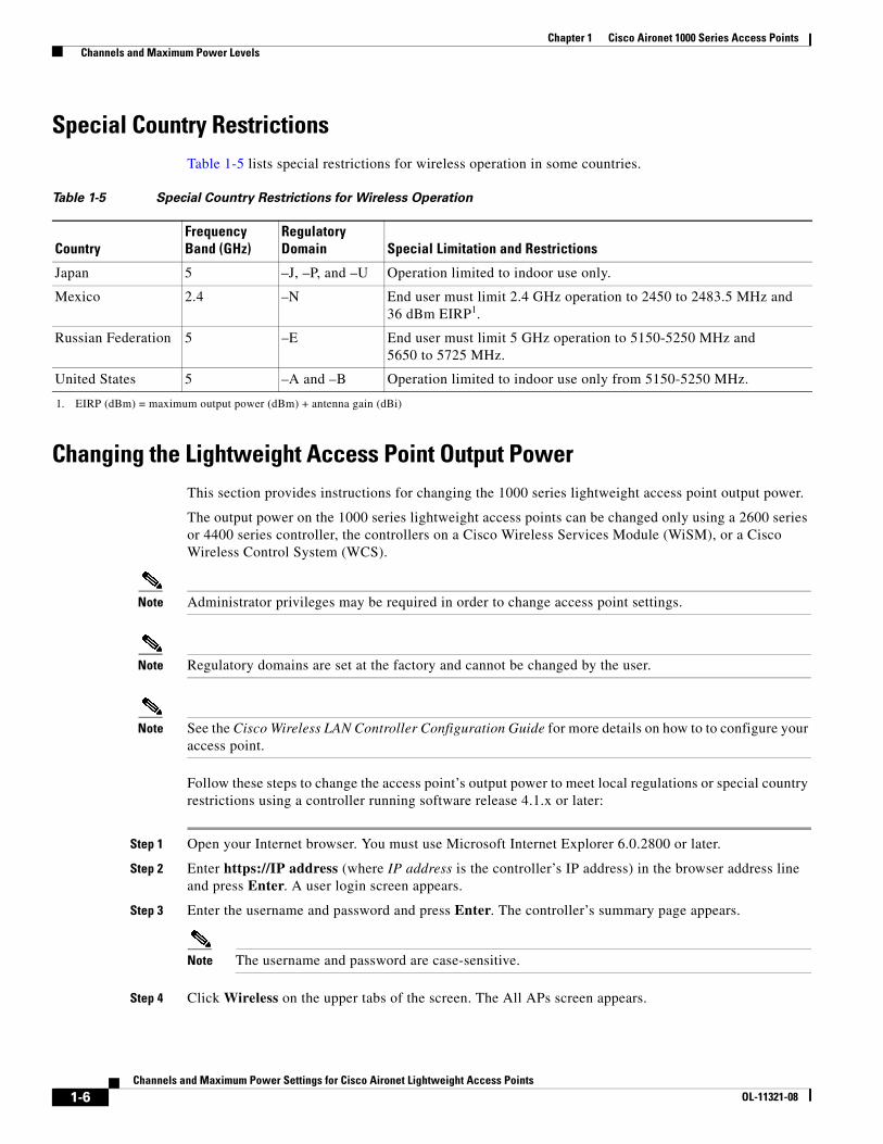
Special Country RestrictionsTable 1-5 lists special restrictions for wireless operation in some countries.
Changing the Lightweight Access Point Output PowerThis section provides instructions for changing the 1000 series lightweight access point output power.
The output power on the 1000 series lightweight access points can be changed only using a 2600 series or 4400 series controller, the controllers on a Cisco Wireless Services Module (WiSM), or a Cisco Wireless Control System (WCS).
Note Administrator privileges may be required in order to change access point settings.
Note Regulatory domains are set at the factory and cannot be changed by the user.
Note See the Cisco Wireless LAN Controller Configuration Guide for more details on how to to configure your access point.
Follow these steps to change the access point’s output power to meet local regulations or special country restrictions using a controller running software release 4.1.x or later:
Step 1 Open your Internet browser. You must use Microsoft Internet Explorer 6.0.2800 or later.
Step 2 Enter https://IP address (where IP address is the controller’s IP address) in the browser address line and press Enter. A user login screen appears.
Step 3 Enter the username and password and press Enter. The controller’s summary page appears.
Note The username and password are case-sensitive.
Step 4 Click Wireless on the upper tabs of the screen. The All APs screen appears.
Table 1-5 Special Country Restrictions for Wireless Operation
CountryFrequency Band (GHz)
Regulatory Domain Special Limitation and Restrictions
Japan 5 –J, –P, and –U Operation limited to indoor use only.
Mexico 2.4 –N End user must limit 2.4 GHz operation to 2450 to 2483.5 MHz and 36 dBm EIRP1.
1. EIRP (dBm) = maximum output power (dBm) + antenna gain (dBi)
Russian Federation 5 –E End user must limit 5 GHz operation to 5150-5250 MHz and 5650 to 5725 MHz.
United States 5 –A and –B Operation limited to indoor use only from 5150-5250 MHz.
1-6Channels and Maximum Power Settings for Cisco Aironet Lightweight Access Points
OL-11321-08
Chapter 1 Cisco Aironet 1000 Series Access Points Channels and Maximum Power Levels
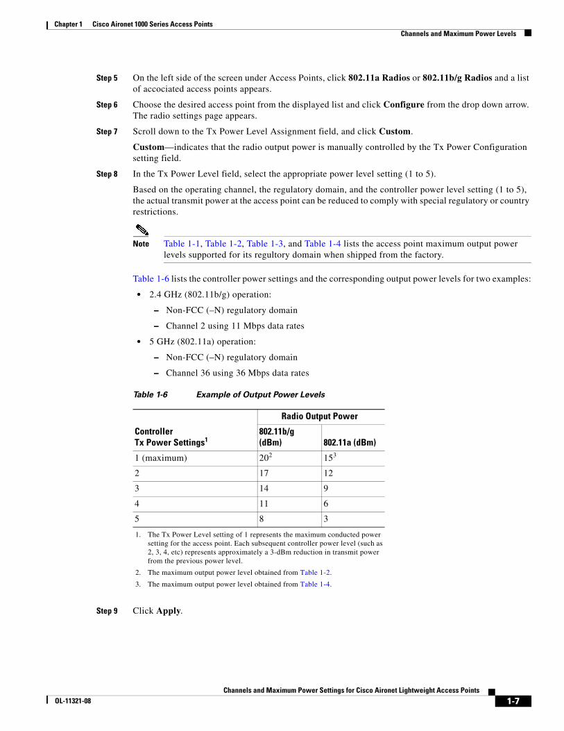
Step 5 On the left side of the screen under Access Points, click 802.11a Radios or 802.11b/g Radios and a list of accociated access points appears.
Step 6 Choose the desired access point from the displayed list and click Configure from the drop down arrow. The radio settings page appears.
Step 7 Scroll down to the Tx Power Level Assignment field, and click Custom.
Custom—indicates that the radio output power is manually controlled by the Tx Power Configuration setting field.
Step 8 In the Tx Power Level field, select the appropriate power level setting (1 to 5).
Based on the operating channel, the regulatory domain, and the controller power level setting (1 to 5), the actual transmit power at the access point can be reduced to comply with special regulatory or country restrictions.
Note Table 1-1, Table 1-2, Table 1-3, and Table 1-4 lists the access point maximum output power levels supported for its regultory domain when shipped from the factory.
Table 1-6 lists the controller power settings and the corresponding output power levels for two examples:
• 2.4 GHz (802.11b/g) operation:
– Non-FCC (–N) regulatory domain
– Channel 2 using 11 Mbps data rates
• 5 GHz (802.11a) operation:
– Non-FCC (–N) regulatory domain
– Channel 36 using 36 Mbps data rates
Step 9 Click Apply.
Table 1-6 Example of Output Power Levels
Controller Tx Power Settings1
1. The Tx Power Level setting of 1 represents the maximum conducted power setting for the access point. Each subsequent controller power level (such as 2, 3, 4, etc) represents approximately a 3-dBm reduction in transmit power from the previous power level.
Radio Output Power
802.11b/g (dBm) 802.11a (dBm)
1 (maximum) 202
2. The maximum output power level obtained from Table 1-2.
153
3. The maximum output power level obtained from Table 1-4.
2 17 12
3 14 9
4 11 6
5 8 3
1-7Channels and Maximum Power Settings for Cisco Aironet Lightweight Access Points
OL-11321-08
Chapter 1 Cisco Aironet 1000 Series Access Points Channels and Maximum Power Levels
Step 10 Close your Internet browser.
For additional configuration information, refer to the Cisco Wireless LAN Controller Configuration Guide.
1-8Channels and Maximum Power Settings for Cisco Aironet Lightweight Access Points
OL-11321-08
Channels and Maximum Power SeOL-11321-08
C H A P T E R 2
Cisco Aironet 1100 Series Access PointsThis chapter lists the 1100 series lightweight (AIR-LAP1121G) access point IEEE 802.11b (2.4-GHz) and IEEE 802.11g (2.4-GHz) channels and the maximum power levels supported by the world’s regulatory domains. For additional product hardware information refer to the Cisco Aironet 1100 Series Access Point Hardware Installation Guide.
The following topics are covered in this chapter:
• Channels, page 2-10
• Maximum Power Levels, page 2-11
• Changing the Lightweight Access Point Output Power, page 2-12
2-9ttings for Cisco Aironet Lightweight Access Points
Chapter 2 Cisco Aironet 1100 Series Access Points Channels
Channels
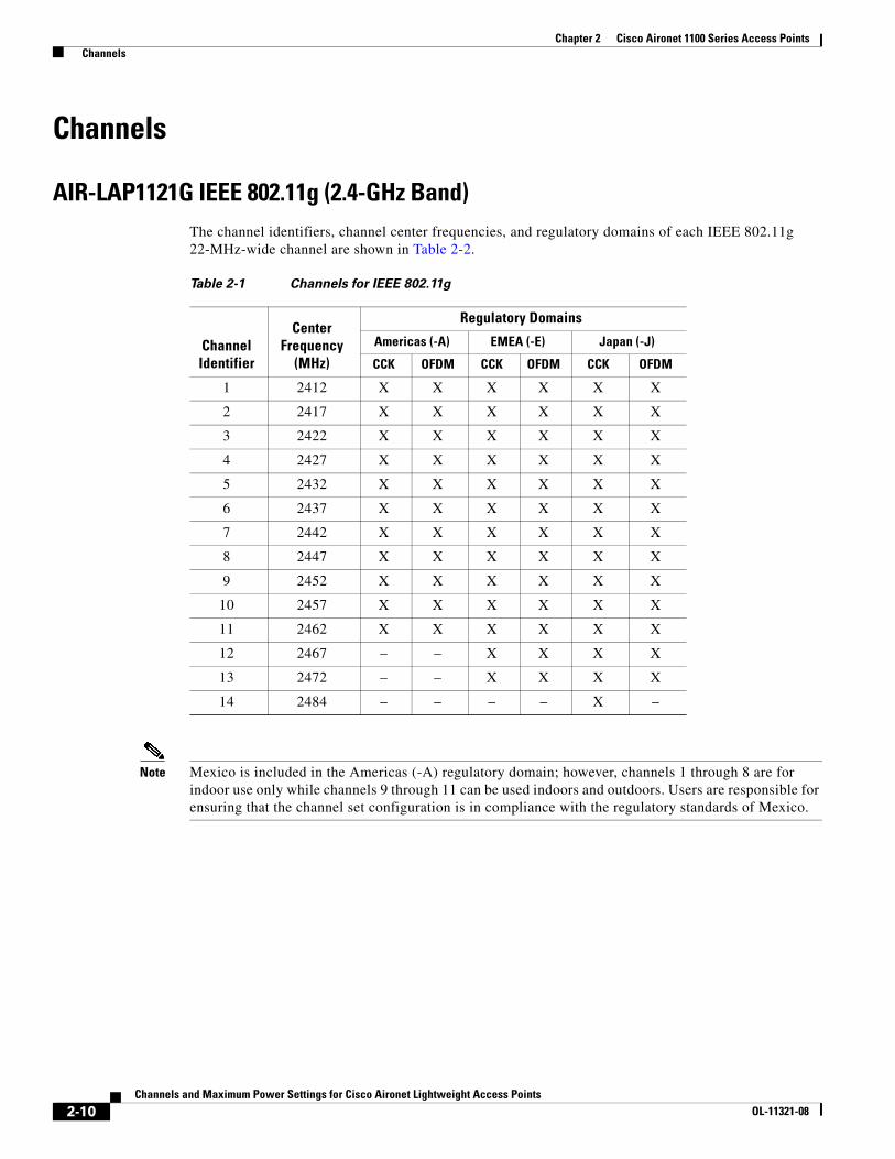
AIR-LAP1121G IEEE 802.11g (2.4-GHz Band)The channel identifiers, channel center frequencies, and regulatory domains of each IEEE 802.11g 22-MHz-wide channel are shown in Table 2-2.
Note Mexico is included in the Americas (-A) regulatory domain; however, channels 1 through 8 are for indoor use only while channels 9 through 11 can be used indoors and outdoors. Users are responsible for ensuring that the channel set configuration is in compliance with the regulatory standards of Mexico.
Table 2-1 Channels for IEEE 802.11g
Channel Identifier
Center Frequency
(MHz)
Regulatory Domains
Americas (-A) EMEA (-E) Japan (-J)
CCK OFDM CCK OFDM CCK OFDM
1 2412 X X X X X X
2 2417 X X X X X X
3 2422 X X X X X X
4 2427 X X X X X X
5 2432 X X X X X X
6 2437 X X X X X X
7 2442 X X X X X X
8 2447 X X X X X X
9 2452 X X X X X X
10 2457 X X X X X X
11 2462 X X X X X X
12 2467 – – X X X X
13 2472 – – X X X X
14 2484 – – – – X –
2-10Channels and Maximum Power Settings for Cisco Aironet Lightweight Access Points
OL-11321-08
Chapter 2 Cisco Aironet 1100 Series Access Points Maximum Power Levels
Maximum Power Levels
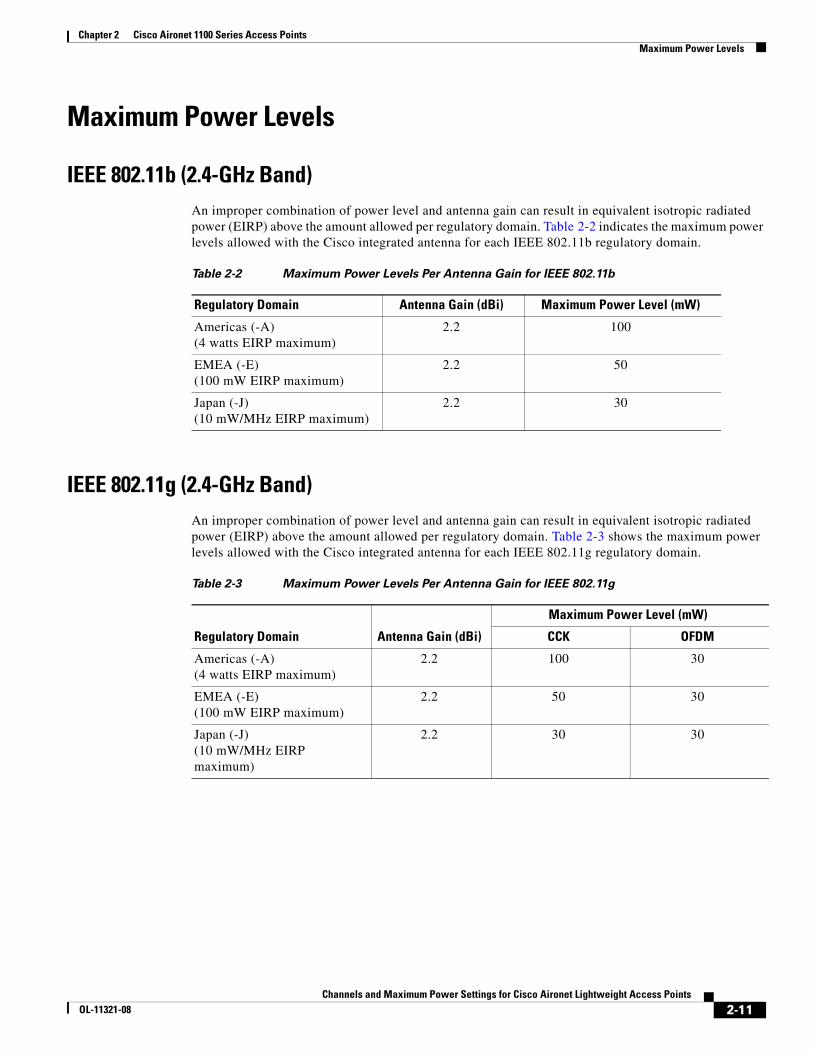
IEEE 802.11b (2.4-GHz Band)An improper combination of power level and antenna gain can result in equivalent isotropic radiated power (EIRP) above the amount allowed per regulatory domain. Table 2-2 indicates the maximum power levels allowed with the Cisco integrated antenna for each IEEE 802.11b regulatory domain.
IEEE 802.11g (2.4-GHz Band)An improper combination of power level and antenna gain can result in equivalent isotropic radiated power (EIRP) above the amount allowed per regulatory domain. Table 2-3 shows the maximum power levels allowed with the Cisco integrated antenna for each IEEE 802.11g regulatory domain.
Table 2-2 Maximum Power Levels Per Antenna Gain for IEEE 802.11b
Regulatory Domain Antenna Gain (dBi) Maximum Power Level (mW)
Americas (-A)(4 watts EIRP maximum)
2.2 100
EMEA (-E)(100 mW EIRP maximum)
2.2 50
Japan (-J)(10 mW/MHz EIRP maximum)
2.2 30
Table 2-3 Maximum Power Levels Per Antenna Gain for IEEE 802.11g
Regulatory Domain Antenna Gain (dBi)
Maximum Power Level (mW)
CCK OFDM
Americas (-A)(4 watts EIRP maximum)
2.2 100 30
EMEA (-E)(100 mW EIRP maximum)
2.2 50 30
Japan (-J)(10 mW/MHz EIRP maximum)
2.2 30 30
2-11Channels and Maximum Power Settings for Cisco Aironet Lightweight Access Points
OL-11321-08
Chapter 2 Cisco Aironet 1100 Series Access Points Changing the Lightweight Access Point Output Power
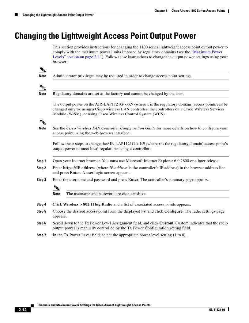
Changing the Lightweight Access Point Output PowerThis section provides instructions for changing the 1100 series lightweight access point output power to comply with the maximum power limits imposed by regulatory domains (see the “Maximum Power Levels” section on page 2-11). Follow these instructions to change the output power settings using your browser:
Note Administrator privileges may be required in order to change access point settings.
Note Regulatory domains are set at the factory and cannot be changed by the user.
The output power on the AIR-LAP1121G-x-K9 (where x is the regulatory domain) access points can be changed only by using a Cisco wireless LAN controller, the controllers on a Cisco Wireless Services
Module (WiSM), or using Cisco Wireless Control System (WCS).
Note See the Cisco Wireless LAN Controller Configuration Guide for more details on how to configure your access point using the web-browser interface.
Follow these steps to change theAIR-LAP1121G-x-K9 (where x is the regulatory domain) access point’s output power to meet local regulations using a controller:
Step 1 Open your Internet browser. You must use Microsoft Internet Explorer 6.0.2800 or a later release.
Step 2 Enter https://IP address (where IP address is the controller’s IP address) in the browser address line and press Enter. A user login screen appears.
Step 3 Enter the username and password and press Enter. The controller’s summary page appears.
Note The username and password are case-sensitive.
Step 4 Click Wireless > 802.11b/g Radio and a list of associated access points appears.
Step 5 Choose the desired access point from the displayed list and click Configure. The radio settings page appears.
Step 6 Scroll down to the Tx Power Level Assignment field, and click Custom. Custom indicates that the radio output power is manually controlled by the Tx Power Configuration setting field.
Step 7 In the Tx Power Level field, select the appropriate power level setting (1 to 8).
2-12Channels and Maximum Power Settings for Cisco Aironet Lightweight Access Points
OL-11321-08
dekurian
Typewritten Text
Chapter 2 Cisco Aironet 1100 Series Access Points Changing the Lightweight Access Point Output Power
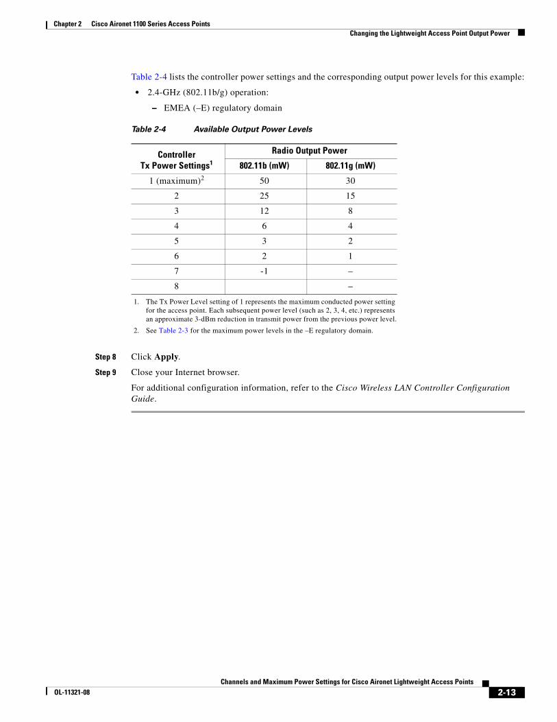
Table 2-4 lists the controller power settings and the corresponding output power levels for this example:
• 2.4-GHz (802.11b/g) operation:
– EMEA (–E) regulatory domain
Step 8 Click Apply.
Step 9 Close your Internet browser.
For additional configuration information, refer to the Cisco Wireless LAN Controller Configuration Guide.
Table 2-4 Available Output Power Levels
Controller Tx Power Settings1
1. The Tx Power Level setting of 1 represents the maximum conducted power setting for the access point. Each subsequent power level (such as 2, 3, 4, etc.) represents an approximate 3-dBm reduction in transmit power from the previous power level.
Radio Output Power
802.11b (mW) 802.11g (mW)
1 (maximum)2
2. See Table 2-3 for the maximum power levels in the –E regulatory domain.
50 30
2 25 15
3 12 8
4 6 4
5 3 2
6 2 1
7 -1 –
8 –
2-13Channels and Maximum Power Settings for Cisco Aironet Lightweight Access Points
OL-11321-08

Chapter 2 Cisco Aironet 1100 Series Access Points Changing the Lightweight Access Point Output Power
2-14Channels and Maximum Power Settings for Cisco Aironet Lightweight Access Points
OL-11321-08

Channels and Maximum Power SeOL-11321-08
C H A P T E R 3
Cisco Aironet 1130 Series Access PointsThis chapter lists the 1130 series lightweight access point (models: AIR-LAP1131G-x-K9 and AIR-LAP1131AG-x-K9) IEEE 802.11b/g (2.4-GHz) and the IEEE 802.11a (5-GHz) channels and maximum power levels supported by the world’s regulatory domains. For additional product hardware information refer to the Cisco Aironet 1130AG Series Access Point Hardware Installation Guide.
The following topics are covered in this chapter:
• Channels and Maximum Power Levels, page 3-3
• Special Country Restrictions, page 3-5
• Changing the Lightweight Access Point Output Power, page 3-5
3-1ttings for Cisco Aironet Lightweight Access Points
Chapter 3 Cisco Aironet 1130 Series Access Points
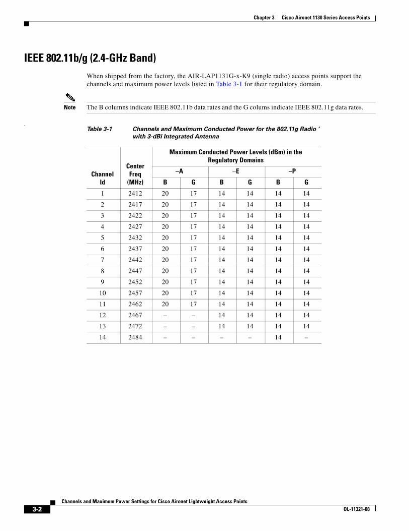
IEEE 802.11b/g (2.4-GHz Band)When shipped from the factory, the AIR-LAP1131G-x-K9 (single radio) access points support the channels and maximum power levels listed in Table 3-1 for their regulatory domain.
Note The B columns indicate IEEE 802.11b data rates and the G colums indicate IEEE 802.11g data rates.
.Table 3-1 Channels and Maximum Conducted Power for the 802.11g Radio ‘
with 3-dBi Integrated Antenna
Channel Id
Center Freq
(MHz)
Maximum Conducted Power Levels (dBm) in the Regulatory Domains
–A –E –P
B G B G B G
1 2412 20 17 14 14 14 14
2 2417 20 17 14 14 14 14
3 2422 20 17 14 14 14 14
4 2427 20 17 14 14 14 14
5 2432 20 17 14 14 14 14
6 2437 20 17 14 14 14 14
7 2442 20 17 14 14 14 14
8 2447 20 17 14 14 14 14
9 2452 20 17 14 14 14 14
10 2457 20 17 14 14 14 14
11 2462 20 17 14 14 14 14
12 2467 – – 14 14 14 14
13 2472 – – 14 14 14 14
14 2484 – – – – 14 –
3-2Channels and Maximum Power Settings for Cisco Aironet Lightweight Access Points
OL-11321-08
Chapter 3 Cisco Aironet 1130 Series Access Points Channels and Maximum Power Levels
Channels and Maximum Power Levels
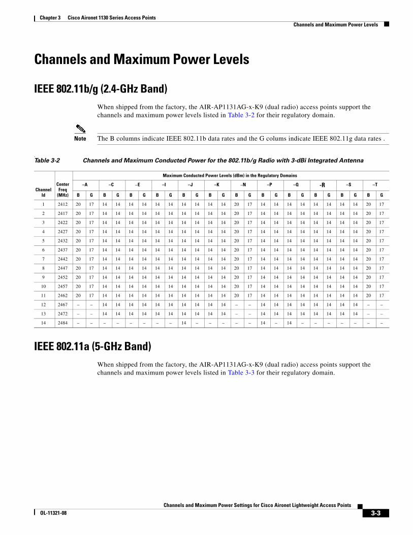
IEEE 802.11b/g (2.4-GHz Band)When shipped from the factory, the AIR-AP1131AG-x-K9 (dual radio) access points support the channels and maximum power levels listed in Table 3-2 for their regulatory domain.
Note The B columns indicate IEEE 802.11b data rates and the G colums indicate IEEE 802.11g data rates .
.
IEEE 802.11a (5-GHz Band)When shipped from the factory, the AIR-AP1131AG-x-K9 (dual radio) access points support the channels and maximum power levels listed in Table 3-3 for their regulatory domain.
Table 3-2 Channels and Maximum Conducted Power for the 802.11b/g Radio with 3-dBi Integrated Antenna
Channel Id
Center Freq
(MHz)
Maximum Conducted Power Levels (dBm) in the Regulatory Domains
–A –C –E –I –J –K –N –P –Q -R –S –T
B G B G B G B G B G B G B G B G B G B G B G B G
1 2412 20 17 14 14 14 14 14 14 14 14 14 14 20 17 14 14 14 14 14 14 14 14 20 17
2 2417 20 17 14 14 14 14 14 14 14 14 14 14 20 17 14 14 14 14 14 14 14 14 20 17
3 2422 20 17 14 14 14 14 14 14 14 14 14 14 20 17 14 14 14 14 14 14 14 14 20 17
4 2427 20 17 14 14 14 14 14 14 14 14 14 14 20 17 14 14 14 14 14 14 14 14 20 17
5 2432 20 17 14 14 14 14 14 14 14 14 14 14 20 17 14 14 14 14 14 14 14 14 20 17
6 2437 20 17 14 14 14 14 14 14 14 14 14 14 20 17 14 14 14 14 14 14 14 14 20 17
7 2442 20 17 14 14 14 14 14 14 14 14 14 14 20 17 14 14 14 14 14 14 14 14 20 17
8 2447 20 17 14 14 14 14 14 14 14 14 14 14 20 17 14 14 14 14 14 14 14 14 20 17
9 2452 20 17 14 14 14 14 14 14 14 14 14 14 20 17 14 14 14 14 14 14 14 14 20 17
10 2457 20 17 14 14 14 14 14 14 14 14 14 14 20 17 14 14 14 14 14 14 14 14 20 17
11 2462 20 17 14 14 14 14 14 14 14 14 14 14 20 17 14 14 14 14 14 14 14 14 20 17
12 2467 – – 14 14 14 14 14 14 14 14 14 14 – – 14 14 14 14 14 14 14 14 – –
13 2472 – – 14 14 14 14 14 14 14 14 14 14 – – 14 14 14 14 14 14 14 14 – –
14 2484 – – – – – – – – 14 – – – – – 14 – 14 – – – – – – –
3-3Channels and Maximum Power Settings for Cisco Aironet Lightweight Access Points
OL-11321-08

Chapter 3 Cisco Aironet 1130 Series Access Points Channels and Maximum Power Levels
Note Access points with FCC Certification Number (LDK102054) do not support dynamic frequency selection (DFS) on channels 100 to 140 in the US, Canada, and the Philippines. The FCC Certification Number (also called FCC ID number) is shown on the product label on the bottom of the unit. Only access points with LDK102054E on the product label and running the 4.1.170.0 software release can support DFS in the US, Canada, and the Philippines.
.Table 3-3 Channels and Maximum Conducted Power for IEEE 802.11a Radio with 4.5-dBI Integrated Antenna
Channel ID
Center Freq
(MHz)
Maximum Conducted Power Levels (dBm) in the Regulatory Domains
–A –C –E –I –J –K –N –P –Q -R –U –S –T
5150 to 5250 MHz
34 5170 – – – – 15 – – – – – – – –
36 5180 15 – 17 17 – 15 15 15 15 17 15 17 –
38 5190 – – – – 15 – – – – – – – –
40 5200 15 – 17 17 – 15 15 15 15 17 15 17 –
42 5210 – – – – 15 – – – – – – – –
44 5220 15 – 17 17 – 15 15 15 15 17 15 17 –
46 5230 – – – – 15 – – – – – – – –
48 5240 15 – 17 17 – 15 15 15 15 17 15 17 –
5250 to 5350 MHz
52 5260 17 – 171
1. Frequencies require DFS (Uniform spreading not required for the –P regulatory domain).
171 – 171 171 151 151 17 – 141 –
56 5280 17 – 171 171 – 171 171 151 151 17 – 141 15
60 5300 17 – 171 171 – 171 171 151 151 17 – 141 15
64 5320 17 – 171 171 – 171 171 151 151 17 – 141 15
5450 to 5725 MHz
100 5500 171 – 171 – – 171 – – 171 – – – 171
104 5520 171 – 171 – – 171 – – 171 – – – 171
108 5540 171 – 171 – – 171 – – 171 – – – 171
112 5560 171 – 171 – – 171 – – 171 – – – 171
116 5580 171 – 171 – – 171 – – 171 – – – 171
120 5600 – – 171 – – 171 – – 171 – – – 171
124 5620 – – 171 – – 171 – – 171 – – – 171
128 5640 – – 171 – – – – – 171 – – – 171
132 5660 171 – 171 – – – – – 171 17 – – 171
136 5680 171 – 171 – – – – – 171 17 – – 171
140 5700 171 – 171 – – – – – 171 17 – – 171
5725 to 5850 MHz
149 5745 17 17 – – – 17 17 – – 17 – 17 17
153 5765 17 17 – – – 17 17 – – 17 – 17 17
157 5785 17 17 – – – 17 17 – – 17 – 17 17
161 5805 17 17 – – – 17 17 – – 17 – 17 17
165 5825 – – – – – – – – – – – – –
3-4Channels and Maximum Power Settings for Cisco Aironet Lightweight Access Points
OL-11321-08
Chapter 3 Cisco Aironet 1130 Series Access Points Special Country Restrictions
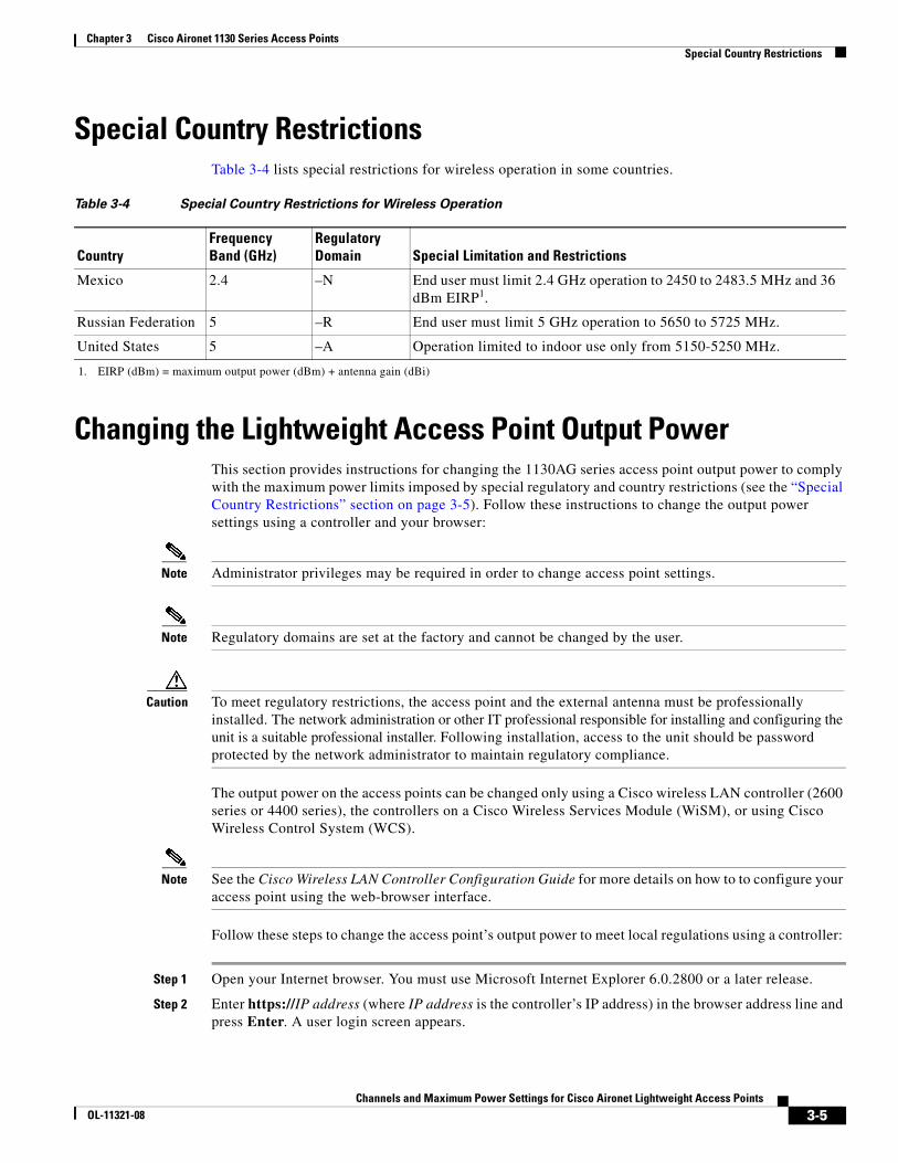
Special Country RestrictionsTable 3-4 lists special restrictions for wireless operation in some countries.
Changing the Lightweight Access Point Output PowerThis section provides instructions for changing the 1130AG series access point output power to comply with the maximum power limits imposed by special regulatory and country restrictions (see the “Special Country Restrictions” section on page 3-5). Follow these instructions to change the output power settings using a controller and your browser:
Note Administrator privileges may be required in order to change access point settings.
Note Regulatory domains are set at the factory and cannot be changed by the user.
Caution To meet regulatory restrictions, the access point and the external antenna must be professionally installed. The network administration or other IT professional responsible for installing and configuring the unit is a suitable professional installer. Following installation, access to the unit should be password protected by the network administrator to maintain regulatory compliance.
The output power on the access points can be changed only using a Cisco wireless LAN controller (2600 series or 4400 series), the controllers on a Cisco Wireless Services Module (WiSM), or using Cisco Wireless Control System (WCS).
Note See the Cisco Wireless LAN Controller Configuration Guide for more details on how to to configure your access point using the web-browser interface.
Follow these steps to change the access point’s output power to meet local regulations using a controller:
Step 1 Open your Internet browser. You must use Microsoft Internet Explorer 6.0.2800 or a later release.
Step 2 Enter https://IP address (where IP address is the controller’s IP address) in the browser address line and press Enter. A user login screen appears.
Table 3-4 Special Country Restrictions for Wireless Operation
CountryFrequency Band (GHz)
Regulatory Domain Special Limitation and Restrictions
Mexico 2.4 –N End user must limit 2.4 GHz operation to 2450 to 2483.5 MHz and 36 dBm EIRP1.
1. EIRP (dBm) = maximum output power (dBm) + antenna gain (dBi)
Russian Federation 5 –R End user must limit 5 GHz operation to 5650 to 5725 MHz.
United States 5 –A Operation limited to indoor use only from 5150-5250 MHz.
3-5Channels and Maximum Power Settings for Cisco Aironet Lightweight Access Points
OL-11321-08
Chapter 3 Cisco Aironet 1130 Series Access Points Changing the Lightweight Access Point Output Power
Step 3 Enter the username and password and press Enter. The controller’s summary page appears.
Note The username and password are case-sensitive.
Step 4 Click Wireless > 802.11a Radios or 802.11b/g Radios and a list of associated access points displays.
Step 5 Choose the desired access point from the displayed list and click Configure. The radio settings page displays.
Step 6 Scroll down to the Tx Power Level Assignment field, and click Custom.
Custom indicates that the radio output power is manually controlled by the Tx Power Configuration setting field.
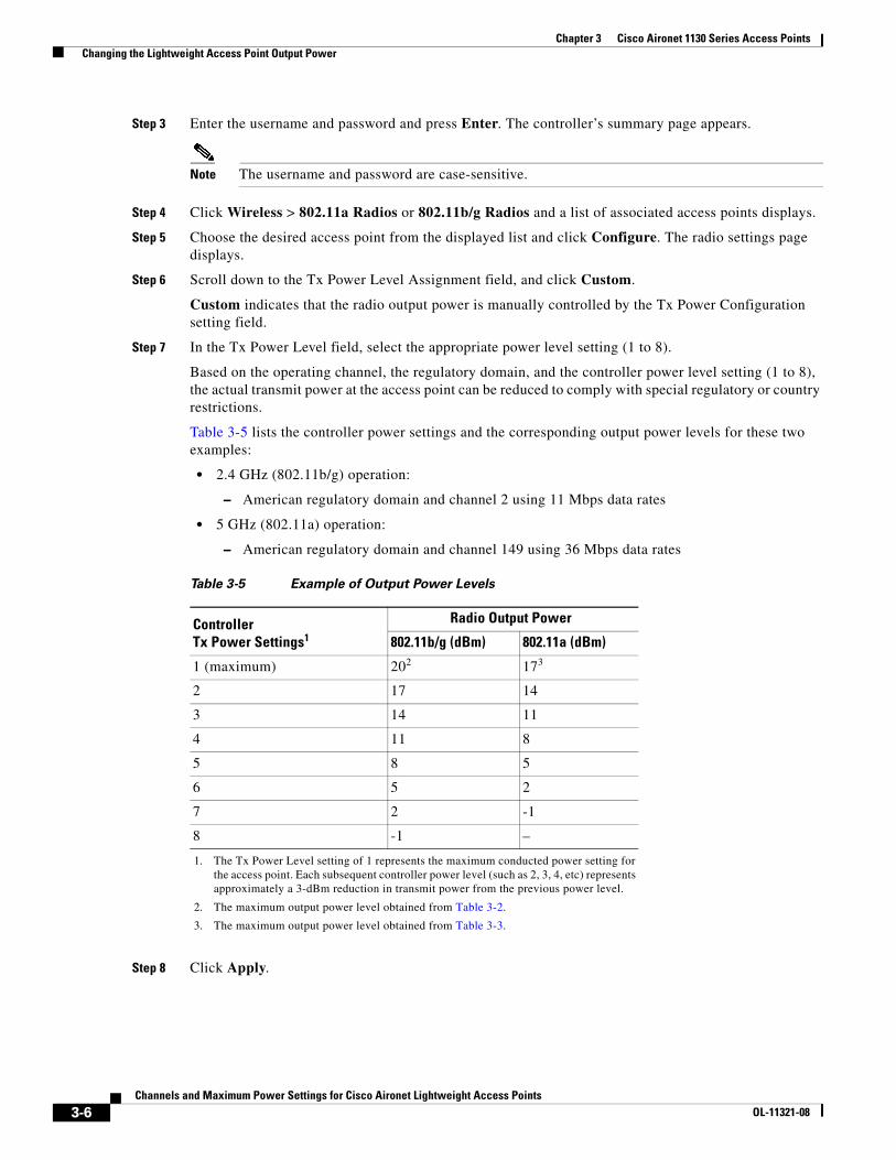
Step 7 In the Tx Power Level field, select the appropriate power level setting (1 to 8).
Based on the operating channel, the regulatory domain, and the controller power level setting (1 to 8), the actual transmit power at the access point can be reduced to comply with special regulatory or country restrictions.
Table 3-5 lists the controller power settings and the corresponding output power levels for these two examples:
• 2.4 GHz (802.11b/g) operation:
– American regulatory domain and channel 2 using 11 Mbps data rates
• 5 GHz (802.11a) operation:
– American regulatory domain and channel 149 using 36 Mbps data rates
Step 8 Click Apply.
Table 3-5 Example of Output Power Levels
Controller Tx Power Settings1
1. The Tx Power Level setting of 1 represents the maximum conducted power setting for the access point. Each subsequent controller power level (such as 2, 3, 4, etc) represents approximately a 3-dBm reduction in transmit power from the previous power level.
Radio Output Power
802.11b/g (dBm) 802.11a (dBm)
1 (maximum) 202
2. The maximum output power level obtained from Table 3-2.
173
3. The maximum output power level obtained from Table 3-3.
2 17 14
3 14 11
4 11 8
5 8 5
6 5 2
7 2 -1
8 -1 –
3-6Channels and Maximum Power Settings for Cisco Aironet Lightweight Access Points
OL-11321-08
Chapter 3 Cisco Aironet 1130 Series Access Points Changing the Lightweight Access Point Output Power
Step 9 Close your Internet browser.
For additional configuration information, refer to the Cisco Wireless LAN Controller Configuration Guide.
3-7Channels and Maximum Power Settings for Cisco Aironet Lightweight Access Points
OL-11321-08
Chapter 3 Cisco Aironet 1130 Series Access Points Changing the Lightweight Access Point Output Power
3-8Channels and Maximum Power Settings for Cisco Aironet Lightweight Access Points
OL-11321-08
Channels and Maximum Power SeOL-11321-08
C H A P T E R 4
Cisco Aironet 1040 and 1140 Series Lightweight Access PointsThis section lists the 1040 and 1140 series lightweight access points (model: AIR-LAP1141) 2.4-GHz and 5-GHz (IEEE 802.11n Draft 2.0) radio channels and maximum power levels supported by the world’s regulatory domains. The following topics are covered in this section:
• Channels and Maximum Power Levels, page 4-2
• Special Country Restrictions, page 4-19
• Changing Lightweight Access Point Output Power, page 4-19
4-1ttings for Cisco Aironet Lightweight Access Points
Chapter 4 Cisco Aironet 1040 and 1140 Series Lightweight Access Points Channels and Maximum Power Levels
Channels and Maximum Power Levels
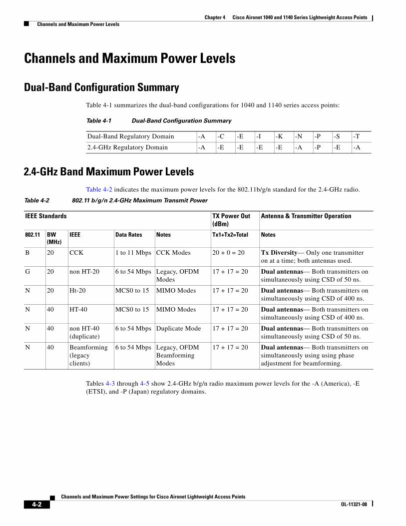
Dual-Band Configuration SummaryTable 4-1 summarizes the dual-band configurations for 1040 and 1140 series access points:
2.4-GHz Band Maximum Power LevelsTable 4-2 indicates the maximum power levels for the 802.11b/g/n standard for the 2.4-GHz radio.
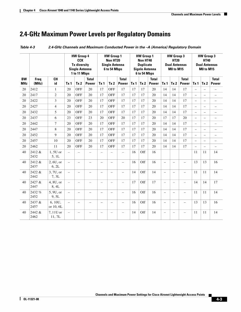
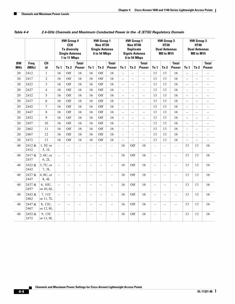
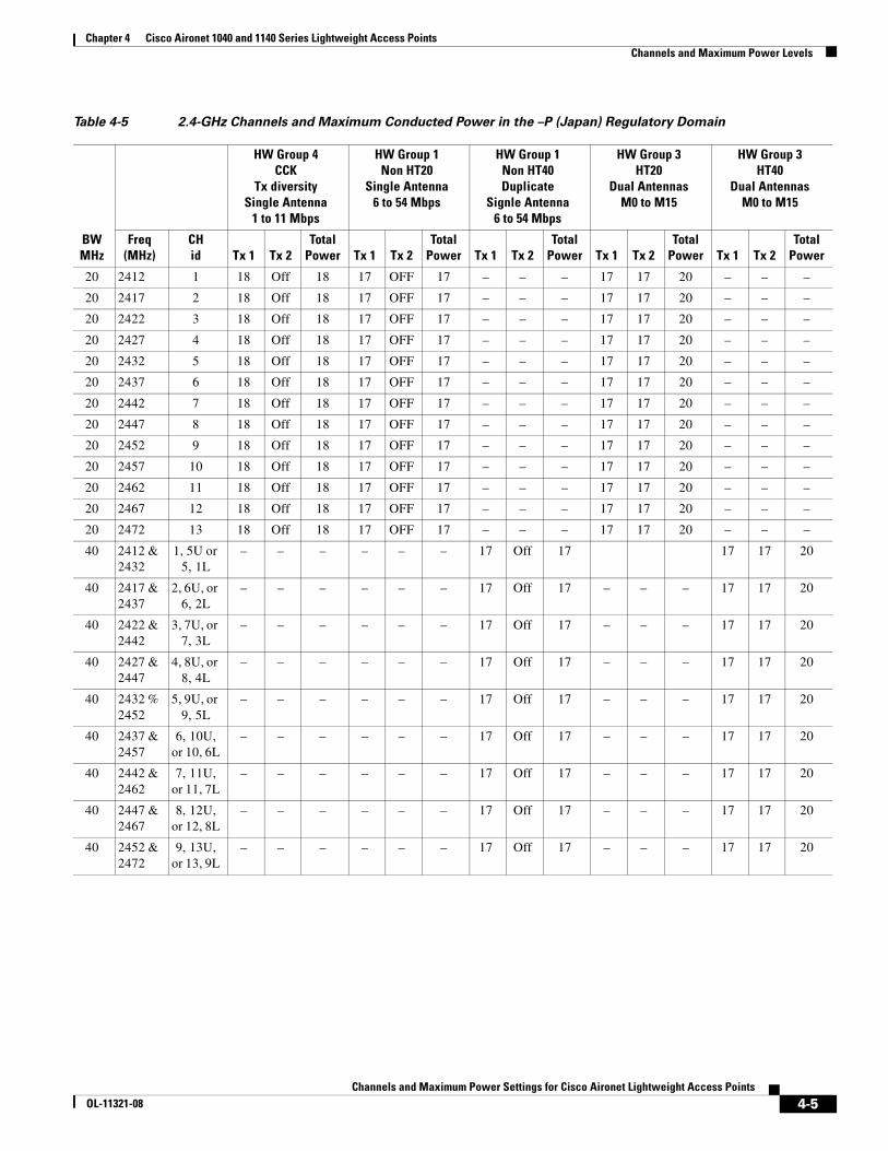
Tables 4-3 through 4-5 show 2.4-GHz b/g/n radio maximum power levels for the -A (America), -E (ETSI), and -P (Japan) regulatory domains.
Table 4-1 Dual-Band Configuration Summary
Dual-Band Regulatory Domain -A -C -E -I -K -N -P -S -T
2.4-GHz Regulatory Domain -A -E -E -E -E -A -P -E -A
Table 4-2 802.11 b/g/n 2.4-GHz Maximum Transmit Power
IEEE Standards TX Power Out (dBm)
Antenna & Transmitter Operation
802.11 BW (MHz)
IEEE Data Rates Notes Tx1+Tx2=Total Notes
B 20 CCK 1 to 11 Mbps CCK Modes 20 + 0 = 20 Tx Diversity— Only one transmitter on at a time; both antennas used.
G 20 non HT-20 6 to 54 Mbps Legacy, OFDM Modes
17 + 17 = 20 Dual antennas— Both transmitters on simultaneously using CSD of 50 ns.
N 20 Ht-20 MCS0 to 15 MIMO Modes 17 + 17 = 20 Dual antennas— Both transmitters on simultaneously using CSD of 400 ns.
N 40 HT-40 MCS0 to 15 MIMO Modes 17 + 17 = 20 Dual antennas— Both transmitters on simultaneously using CSD of 400 ns.
N 40 non HT-40 (duplicate)
6 to 54 Mbps Duplicate Mode 17 + 17 = 20 Dual antennas— Both transmitters on simultaneously using CSD of 50 ns.
N 40 Beamforming (legacy clients)
6 to 54 Mbps Legacy, OFDM Beamforming Modes
17 + 17 = 20 Dual antennas— Both transmitters on simultaneously using using phase adjustment for beamforming.
4-2Channels and Maximum Power Settings for Cisco Aironet Lightweight Access Points
OL-11321-08
Chapter 4 Cisco Aironet 1040 and 1140 Series Lightweight Access Points Channels and Maximum Power Levels
2.4-GHz Maximum Power Levels per Regulatory Domains
Table 4-3 2.4-GHz Channels and Maximum Conducted Power in the –A (America) Regulatory Domain
BWMHz
HW Group 4 CCK
Tx diversity Single Antenna
1 to 11 Mbps
HW Group 1Non HT20
Single Antenna6 to 54 Mbps
HW Group 1Non HT40Duplicate
Signle Antenna6 to 54 Mbps
HW Group 3HT20
Dual AntennasM0 to M15
HW Group 3HT40
Dual AntennasM0 to M15
Freq (MHz)
CHid Tx 1 Tx 2
TotalPower Tx 1 Tx 2
TotalPower Tx 1 Tx 2
TotalPower Tx 1 Tx 2
TotalPower Tx 1 Tx 2
TotalPower
20 2412 1 20 OFF 20 17 OFF 17 17 17 20 14 14 17 – – –
20 2417 2 20 OFF 20 17 OFF 17 17 17 20 14 14 17 – – –
20 2422 3 20 OFF 20 17 OFF 17 17 17 20 14 14 17 – – –
20 2427 4 20 OFF 20 17 OFF 17 17 17 20 14 14 17 – – –
20 2432 5 20 OFF 20 17 OFF 17 17 17 20 14 14 17 – – –
20 2437 6 23 OFF 23 20 OFF 20 17 17 20 17 17 20 – – –
20 2442 7 20 OFF 20 17 OFF 17 17 17 20 14 14 17 – – –
20 2447 8 20 OFF 20 17 OFF 17 17 17 20 14 14 17 – – –
20 2452 9 20 OFF 20 17 OFF 17 17 17 20 14 14 17 – – –
20 2457 10 20 OFF 20 17 OFF 17 17 17 20 14 14 17 – – –
20 2462 11 20 OFF 20 17 OFF 17 17 17 20 14 14 17 – – –
40 2412 & 2432
1, 5U or 5, 1L
– – – – – – 16 Off 16 11 11 14
40 2412 & 2437
2, 6U, or 6, 2L
– – – – – – 16 Off 16 – – – 13 13 16
40 2422 & 2442
3, 7U, or 7, 3L
– – – – – – 14 Off 14 – – – 11 11 14
40 2427 & 2447
4, 8U, or 8, 4L
– – – – – – 17 Off 17 – – – 14 14 17
40 2432 % 2452
5, 9U, or 9, 5L
– – – – – – 16 Off 16 – – – 11 11 14
40 2437 & 2457
6, 10U, or 10, 6L
– – – – – – 16 Off 16 – – – 13 13 16
40 2442 & 2462
7, 11U or 11, 7L
– – – – – – 14 Off 14 – – – 11 11 14
4-3Channels and Maximum Power Settings for Cisco Aironet Lightweight Access Points
OL-11321-08
Chapter 4 Cisco Aironet 1040 and 1140 Series Lightweight Access Points Channels and Maximum Power Levels
Table 4-4 2.4-GHz Channels and Maximum Conducted Power in the –E (ETSI) Regulatory Domain
BWMHz
HW Group 4 CCK
Tx diversity Single Antenna
1 to 11 Mbps
HW Group 1Non HT20
Single Antenna6 to 54 Mbps
HW Group 1Non HT40Duplicate
Signle Antenna6 to 54 Mbps
HW Group 3HT20
Dual AntennasM0 to M15
HW Group 3HT40
Dual AntennasM0 to M15
Freq (MHz)
CHid Tx 1 Tx 2
TotalPower Tx 1 Tx 2
TotalPower Tx 1 Tx 2
TotalPower Tx 1 Tx 2
TotalPower Tx 1 Tx 2
TotalPower
20 2412 1 16 Off 16 16 Off 16 – – – 13 13 16 – – –
20 2417 2 16 Off 16 16 Off 16 – – – 13 13 16 – – –
20 2422 3 16 Off 16 16 Off 16 – – – 13 13 16 – – –
20 2427 4 16 Off 16 16 Off 16 – – – 13 13 16 – – –
20 2432 5 16 Off 16 16 Off 16 – – – 13 13 16 – – –
20 2437 6 16 Off 16 16 Off 16 – – – 13 13 16 – – –
20 2442 7 16 Off 16 16 Off 16 – – – 13 13 16 – – –
20 2447 8 16 Off 16 16 Off 16 – – – 13 13 16 – – –
20 2452 9 16 Off 16 16 Off 16 – – – 13 13 16 – – –
20 2457 10 16 Off 16 16 Off 16 – – – 13 13 16 – – –
20 2462 11 16 Off 16 16 Off 16 – – – 13 13 16 – – –
20 2467 12 16 Off 16 16 Off 16 – – – 13 13 16 – – –
20 2472 13 16 Off 16 16 Off 16 – – – 13 13 16 – – –
40 2412 & 2432
1, 5U or 5, 1L
– – – – – – 16 Off 16 – – – 13 13 16
40 2417 & 2437
2, 6U, or 6, 2L
– – – – – – 16 Off 16 – – – 13 13 16
40 2422 & 2442
3, 7U, or 7, 3L
– – – – – – 16 Off 16 – – – 13 13 16
40 2427 & 2447
4, 8U, or 8, 4L
– – – – – – 16 Off 16 – – – 13 13 16
40 2437 & 2457
6, 10U, or 10, 6L
– – – – – – 16 Off 16 – – – 13 13 16
40 2442 & 2462
7, 11U or 11, 7L
– – – – – – 16 Off 16 – – – 13 13 16
40 2447 & 2467
8, 12U, or 12, 8L
– – – – – – 16 Off 16 – – – 13 13 16
40 2452 & 2472
9, 13U or 13, 9L
– – – – – – 16 Off 16 – – – 13 13 16
4-4Channels and Maximum Power Settings for Cisco Aironet Lightweight Access Points
OL-11321-08
Chapter 4 Cisco Aironet 1040 and 1140 Series Lightweight Access Points Channels and Maximum Power Levels
Table 4-5 2.4-GHz Channels and Maximum Conducted Power in the –P (Japan) Regulatory Domain
BWMHz
HW Group 4 CCK
Tx diversity Single Antenna
1 to 11 Mbps
HW Group 1Non HT20
Single Antenna6 to 54 Mbps
HW Group 1Non HT40Duplicate
Signle Antenna6 to 54 Mbps
HW Group 3HT20
Dual AntennasM0 to M15
HW Group 3HT40
Dual AntennasM0 to M15
Freq (MHz)
CHid Tx 1 Tx 2
TotalPower Tx 1 Tx 2
TotalPower Tx 1 Tx 2
TotalPower Tx 1 Tx 2
TotalPower Tx 1 Tx 2
TotalPower
20 2412 1 18 Off 18 17 OFF 17 – – – 17 17 20 – – –
20 2417 2 18 Off 18 17 OFF 17 – – – 17 17 20 – – –
20 2422 3 18 Off 18 17 OFF 17 – – – 17 17 20 – – –
20 2427 4 18 Off 18 17 OFF 17 – – – 17 17 20 – – –
20 2432 5 18 Off 18 17 OFF 17 – – – 17 17 20 – – –
20 2437 6 18 Off 18 17 OFF 17 – – – 17 17 20 – – –
20 2442 7 18 Off 18 17 OFF 17 – – – 17 17 20 – – –
20 2447 8 18 Off 18 17 OFF 17 – – – 17 17 20 – – –
20 2452 9 18 Off 18 17 OFF 17 – – – 17 17 20 – – –
20 2457 10 18 Off 18 17 OFF 17 – – – 17 17 20 – – –
20 2462 11 18 Off 18 17 OFF 17 – – – 17 17 20 – – –
20 2467 12 18 Off 18 17 OFF 17 – – – 17 17 20 – – –
20 2472 13 18 Off 18 17 OFF 17 – – – 17 17 20 – – –
40 2412 & 2432
1, 5U or 5, 1L
– – – – – – 17 Off 17 17 17 20
40 2417 & 2437
2, 6U, or 6, 2L
– – – – – – 17 Off 17 – – – 17 17 20
40 2422 & 2442
3, 7U, or 7, 3L
– – – – – – 17 Off 17 – – – 17 17 20
40 2427 & 2447
4, 8U, or 8, 4L
– – – – – – 17 Off 17 – – – 17 17 20
40 2432 % 2452
5, 9U, or 9, 5L
– – – – – – 17 Off 17 – – – 17 17 20
40 2437 & 2457
6, 10U, or 10, 6L
– – – – – – 17 Off 17 – – – 17 17 20
40 2442 & 2462
7, 11U, or 11, 7L
– – – – – – 17 Off 17 – – – 17 17 20
40 2447 & 2467
8, 12U, or 12, 8L
– – – – – – 17 Off 17 – – – 17 17 20
40 2452 & 2472
9, 13U, or 13, 9L
– – – – – – 17 Off 17 – – – 17 17 20
4-5Channels and Maximum Power Settings for Cisco Aironet Lightweight Access Points
OL-11321-08
Chapter 4 Cisco Aironet 1040 and 1140 Series Lightweight Access Points Channels and Maximum Power Levels
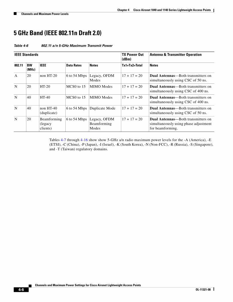
5 GHz Band (IEEE 802.11n Draft 2.0)
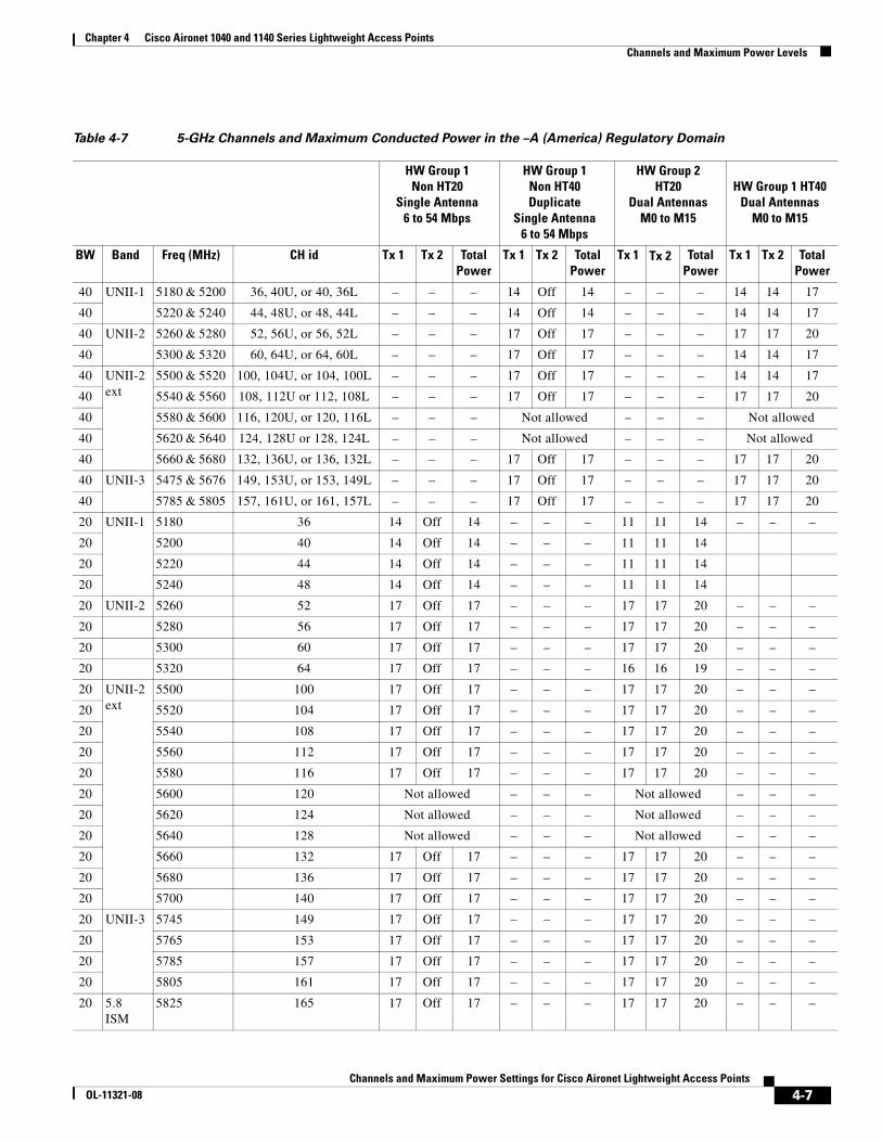
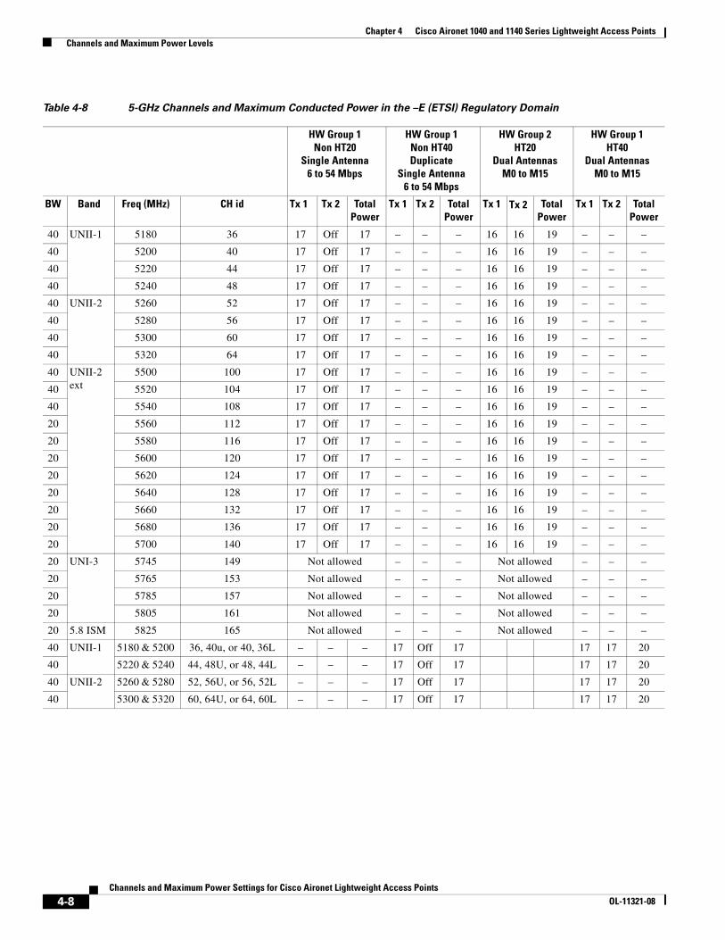
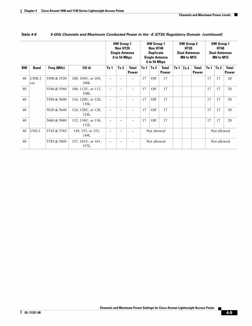
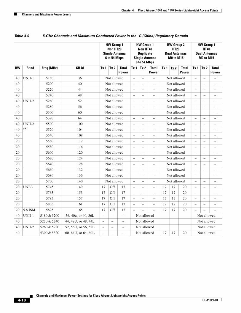
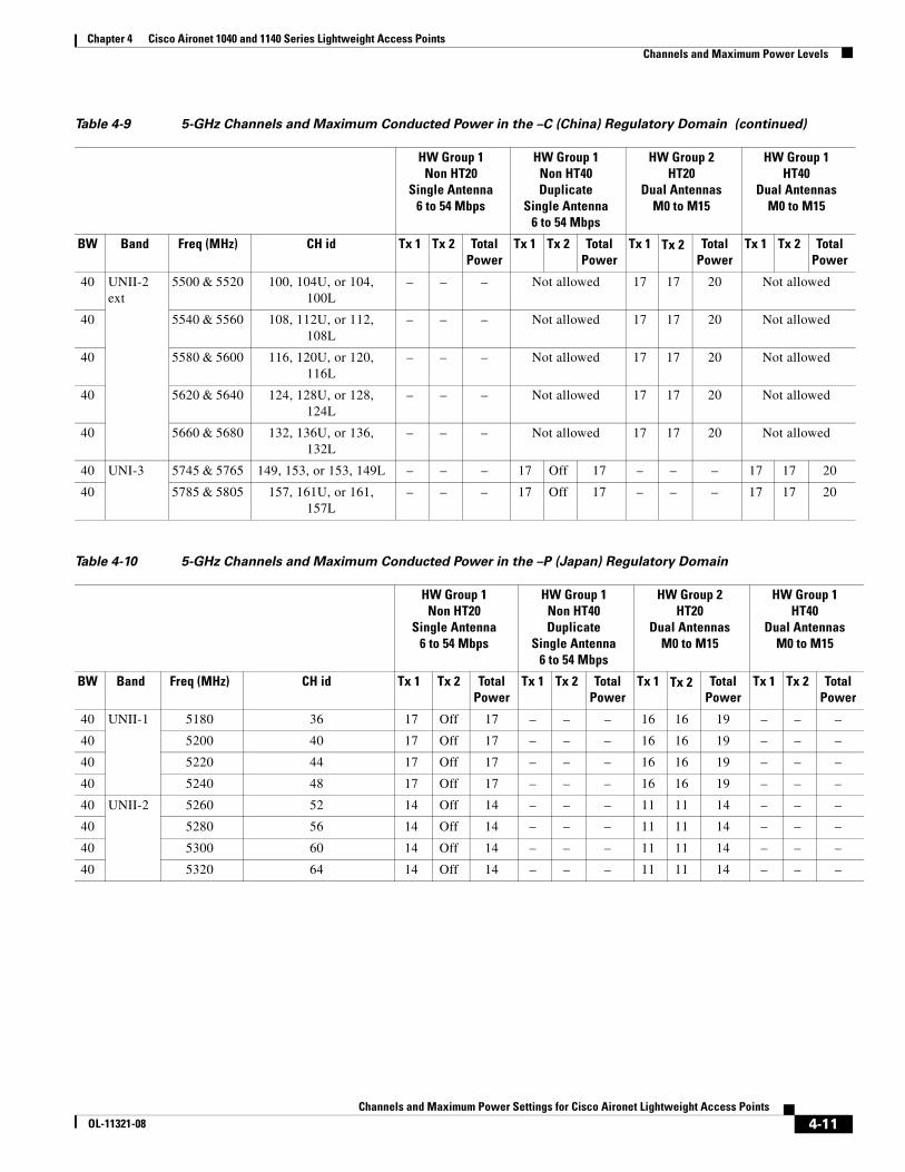
Tables 4-7 through 4-16 show show 5-GHz a/n radio maximum power levels for the -A (America), -E (ETSI), -C (China), -P (Japan), -I (Israel), -K (South Korea), -N (Non-FCC), -R (Russia), -S (Singapore), and -T (Taiwan) regulatory domains.
Table 4-6 802.11 a/n 5-GHz Maximum Transmit Power
IEEE Standards TX Power Out (dBm)
Antenna & Transmitter Operation
802.11 BW (MHz)
IEEE Data Rates Notes Tx1+Tx2=Total Notes
A 20 non HT-20 6 to 54 Mbps Legacy, OFDM Modes
17 + 17 = 20 Dual Antennas—Both transmitters on simultaneously using CSC of 50 ns.
N 20 HT-20 MCS0 to 15 MIMO Modes 17 + 17 = 20 Dual Antennas—Both transmitters on simultaneously using CSC of 400 ns.
N 40 HT-40 MCS0 to 15 MIMO Modes 17 + 17 = 20 Dual Antennas—Both transmitters on simultaneously using CSC of 400 ns.
N 40 non HT-40 (duplicate)
6 to 54 Mbps Duplicate Mode 17 + 17 = 20 Dual Antennas—Both transmitters on simultaneously using CSC of 50 ns.
N 20 Beamforming (legacy clients)
6 to 54 Mbps Legacy, OFDM Beamforming Modes
17 + 17 = 20 Dual Antennas—Both transmitters on simultaneously using phase adjustment for beamforming.
4-6Channels and Maximum Power Settings for Cisco Aironet Lightweight Access Points
OL-11321-08
Chapter 4 Cisco Aironet 1040 and 1140 Series Lightweight Access Points Channels and Maximum Power Levels
Table 4-7 5-GHz Channels and Maximum Conducted Power in the –A (America) Regulatory Domain
HW Group 1 Non HT20
Single Antenna6 to 54 Mbps
HW Group 1 Non HT40Duplicate
Single Antenna6 to 54 Mbps
HW Group 2HT20
Dual Antennas M0 to M15
HW Group 1 HT40Dual Antennas
M0 to M15
BW Band Freq (MHz) CH id Tx 1 Tx 2 TotalPower
Tx 1 Tx 2 TotalPower
Tx 1 Tx 2 TotalPower
Tx 1 Tx 2 TotalPower
40 UNII-1 5180 & 5200 36, 40U, or 40, 36L – – – 14 Off 14 – – – 14 14 17
40 5220 & 5240 44, 48U, or 48, 44L – – – 14 Off 14 – – – 14 14 17
40 UNII-2 5260 & 5280 52, 56U, or 56, 52L – – – 17 Off 17 – – – 17 17 20
40 5300 & 5320 60, 64U, or 64, 60L – – – 17 Off 17 – – – 14 14 17
40 UNII-2 ext
5500 & 5520 100, 104U, or 104, 100L – – – 17 Off 17 – – – 14 14 17
40 5540 & 5560 108, 112U or 112, 108L – – – 17 Off 17 – – – 17 17 20
40 5580 & 5600 116, 120U, or 120, 116L – – – Not allowed – – – Not allowed
40 5620 & 5640 124, 128U or 128, 124L – – – Not allowed – – – Not allowed
40 5660 & 5680 132, 136U, or 136, 132L – – – 17 Off 17 – – – 17 17 20
40 UNII-3 5475 & 5676 149, 153U, or 153, 149L – – – 17 Off 17 – – – 17 17 20
40 5785 & 5805 157, 161U, or 161, 157L – – – 17 Off 17 – – – 17 17 20
20 UNII-1 5180 36 14 Off 14 – – – 11 11 14 – – –
20 5200 40 14 Off 14 – – – 11 11 14
20 5220 44 14 Off 14 – – – 11 11 14
20 5240 48 14 Off 14 – – – 11 11 14
20 UNII-2 5260 52 17 Off 17 – – – 17 17 20 – – –
20 5280 56 17 Off 17 – – – 17 17 20 – – –
20 5300 60 17 Off 17 – – – 17 17 20 – – –
20 5320 64 17 Off 17 – – – 16 16 19 – – –
20 UNII-2 ext
5500 100 17 Off 17 – – – 17 17 20 – – –
20 5520 104 17 Off 17 – – – 17 17 20 – – –
20 5540 108 17 Off 17 – – – 17 17 20 – – –
20 5560 112 17 Off 17 – – – 17 17 20 – – –
20 5580 116 17 Off 17 – – – 17 17 20 – – –
20 5600 120 Not allowed – – – Not allowed – – –
20 5620 124 Not allowed – – – Not allowed – – –
20 5640 128 Not allowed – – – Not allowed – – –
20 5660 132 17 Off 17 – – – 17 17 20 – – –
20 5680 136 17 Off 17 – – – 17 17 20 – – –
20 5700 140 17 Off 17 – – – 17 17 20 – – –
20 UNII-3 5745 149 17 Off 17 – – – 17 17 20 – – –
20 5765 153 17 Off 17 – – – 17 17 20 – – –
20 5785 157 17 Off 17 – – – 17 17 20 – – –
20 5805 161 17 Off 17 – – – 17 17 20 – – –
20 5.8 ISM
5825 165 17 Off 17 – – – 17 17 20 – – –
4-7Channels and Maximum Power Settings for Cisco Aironet Lightweight Access Points
OL-11321-08
Chapter 4 Cisco Aironet 1040 and 1140 Series Lightweight Access Points Channels and Maximum Power Levels
Table 4-8 5-GHz Channels and Maximum Conducted Power in the –E (ETSI) Regulatory Domain
HW Group 1 Non HT20
Single Antenna6 to 54 Mbps
HW Group 1 Non HT40Duplicate
Single Antenna6 to 54 Mbps
HW Group 2HT20
Dual Antennas M0 to M15
HW Group 1 HT40
Dual AntennasM0 to M15
BW Band Freq (MHz) CH id Tx 1 Tx 2 TotalPower
Tx 1 Tx 2 TotalPower
Tx 1 Tx 2 TotalPower
Tx 1 Tx 2 TotalPower
40 UNII-1 5180 36 17 Off 17 – – – 16 16 19 – – –
40 5200 40 17 Off 17 – – – 16 16 19 – – –
40 5220 44 17 Off 17 – – – 16 16 19 – – –
40 5240 48 17 Off 17 – – – 16 16 19 – – –
40 UNII-2 5260 52 17 Off 17 – – – 16 16 19 – – –
40 5280 56 17 Off 17 – – – 16 16 19 – – –
40 5300 60 17 Off 17 – – – 16 16 19 – – –
40 5320 64 17 Off 17 – – – 16 16 19 – – –
40 UNII-2 ext
5500 100 17 Off 17 – – – 16 16 19 – – –
40 5520 104 17 Off 17 – – – 16 16 19 – – –
40 5540 108 17 Off 17 – – – 16 16 19 – – –
20 5560 112 17 Off 17 – – – 16 16 19 – – –
20 5580 116 17 Off 17 – – – 16 16 19 – – –
20 5600 120 17 Off 17 – – – 16 16 19 – – –
20 5620 124 17 Off 17 – – – 16 16 19 – – –
20 5640 128 17 Off 17 – – – 16 16 19 – – –
20 5660 132 17 Off 17 – – – 16 16 19 – – –
20 5680 136 17 Off 17 – – – 16 16 19 – – –
20 5700 140 17 Off 17 – – – 16 16 19 – – –
20 UNI-3 5745 149 Not allowed – – – Not allowed – – –
20 5765 153 Not allowed – – – Not allowed – – –
20 5785 157 Not allowed – – – Not allowed – – –
20 5805 161 Not allowed – – – Not allowed – – –
20 5.8 ISM 5825 165 Not allowed – – – Not allowed – – –
40 UNII-1 5180 & 5200 36, 40u, or 40, 36L – – – 17 Off 17 17 17 20
40 5220 & 5240 44, 48U, or 48, 44L – – – 17 Off 17 17 17 20
40 UNII-2 5260 & 5280 52, 56U, or 56, 52L – – – 17 Off 17 17 17 20
40 5300 & 5320 60, 64U, or 64, 60L – – – 17 Off 17 17 17 20
4-8Channels and Maximum Power Settings for Cisco Aironet Lightweight Access Points
OL-11321-08
Chapter 4 Cisco Aironet 1040 and 1140 Series Lightweight Access Points Channels and Maximum Power Levels
40 UNII-2 ext
5500 & 5520 100, 104U, or 104, 100L
– – – 17 Off 17 17 17 20
40 5540 & 5560 108, 112U, or 112, 108L
– – – 17 Off 17 17 17 20
40 5580 & 5600 116, 120U, or 120, 116L
– – – 17 Off 17 17 17 20
40 5620 & 5640 124, 128U, or 128, 124L
– – – 17 Off 17 17 17 20
40 5660 & 5680 132, 136U, or 136, 132L
– – – 17 Off 17 17 17 20
40 UNI-3 5745 & 5765 149, 153, or 153, 149L
– – – Not allowed Not allowed
40 5785 & 5805 157, 161U, or 161, 157L
– – – Not allowed Not allowed
Table 4-8 5-GHz Channels and Maximum Conducted Power in the –E (ETSI) Regulatory Domain (continued)
HW Group 1 Non HT20
Single Antenna6 to 54 Mbps
HW Group 1 Non HT40Duplicate
Single Antenna6 to 54 Mbps
HW Group 2HT20
Dual Antennas M0 to M15
HW Group 1 HT40
Dual AntennasM0 to M15
BW Band Freq (MHz) CH id Tx 1 Tx 2 TotalPower
Tx 1 Tx 2 TotalPower
Tx 1 Tx 2 TotalPower
Tx 1 Tx 2 TotalPower
4-9Channels and Maximum Power Settings for Cisco Aironet Lightweight Access Points
OL-11321-08
Chapter 4 Cisco Aironet 1040 and 1140 Series Lightweight Access Points Channels and Maximum Power Levels
Table 4-9 5-GHz Channels and Maximum Conducted Power in the –C (China) Regulatory Domain
HW Group 1 Non HT20
Single Antenna6 to 54 Mbps
HW Group 1 Non HT40Duplicate
Single Antenna6 to 54 Mbps
HW Group 2HT20
Dual Antennas M0 to M15
HW Group 1 HT40
Dual AntennasM0 to M15
BW Band Freq (MHz) CH id Tx 1 Tx 2 TotalPower
Tx 1 Tx 2 TotalPower
Tx 1 Tx 2 TotalPower
Tx 1 Tx 2 TotalPower
40 UNII-1 5180 36 Not allowed – – – Not allowed – – –
40 5200 40 Not allowed – – – Not allowed – – –
40 5220 44 Not allowed – – – Not allowed – – –
40 5240 48 Not allowed – – – Not allowed – – –
40 UNII-2 5260 52 Not allowed – – – Not allowed – – –
40 5280 56 Not allowed – – – Not allowed – – –
40 5300 60 Not allowed – – – Not allowed – – –
40 5320 64 Not allowed – – – Not allowed – – –
40 UNII-2 ext
5500 100 Not allowed – – – Not allowed – – –
40 5520 104 Not allowed – – – Not allowed – – –
40 5540 108 Not allowed – – – Not allowed – – –
20 5560 112 Not allowed – – – Not allowed – – –
20 5580 116 Not allowed – – – Not allowed – – –
20 5600 120 Not allowed – – – Not allowed – – –
20 5620 124 Not allowed – – – Not allowed – – –
20 5640 128 Not allowed – – – Not allowed – – –
20 5660 132 Not allowed – – – Not allowed – – –
20 5680 136 Not allowed – – – Not allowed – – –
20 5700 140 Not allowed – – – Not allowed – – –
20 UNI-3 5745 149 17 Off 17 – – – 17 17 20 – – –
20 5765 153 17 Off 17 – – – 17 17 20 – – –
20 5785 157 17 Off 17 – – – 17 17 20 – – –
20 5805 161 17 Off 17 – – – 17 17 20 – – –
20 5.8 ISM 5825 165 17 Off 17 – – – 17 17 20 – – –
40 UNII-1 5180 & 5200 36, 40u, or 40, 36L – – – Not allowed Not allowed
40 5220 & 5240 44, 48U, or 48, 44L – – – Not allowed Not allowed
40 UNII-2 5260 & 5280 52, 56U, or 56, 52L – – – Not allowed Not allowed
40 5300 & 5320 60, 64U, or 64, 60L – – – Not allowed 17 17 20 Not allowed
4-10Channels and Maximum Power Settings for Cisco Aironet Lightweight Access Points
OL-11321-08
Chapter 4 Cisco Aironet 1040 and 1140 Series Lightweight Access Points Channels and Maximum Power Levels
40 UNII-2 ext
5500 & 5520 100, 104U, or 104, 100L
– – – Not allowed 17 17 20 Not allowed
40 5540 & 5560 108, 112U, or 112, 108L
– – – Not allowed 17 17 20 Not allowed
40 5580 & 5600 116, 120U, or 120, 116L
– – – Not allowed 17 17 20 Not allowed
40 5620 & 5640 124, 128U, or 128, 124L
– – – Not allowed 17 17 20 Not allowed
40 5660 & 5680 132, 136U, or 136, 132L
– – – Not allowed 17 17 20 Not allowed
40 UNI-3 5745 & 5765 149, 153, or 153, 149L – – – 17 Off 17 – – – 17 17 20
40 5785 & 5805 157, 161U, or 161, 157L
– – – 17 Off 17 – – – 17 17 20
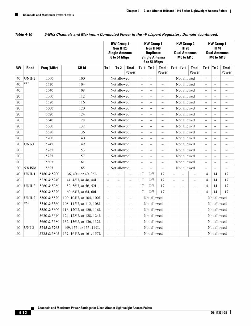
Table 4-10 5-GHz Channels and Maximum Conducted Power in the –P (Japan) Regulatory Domain
HW Group 1 Non HT20
Single Antenna6 to 54 Mbps
HW Group 1 Non HT40Duplicate
Single Antenna6 to 54 Mbps
HW Group 2HT20
Dual Antennas M0 to M15
HW Group 1 HT40
Dual AntennasM0 to M15
BW Band Freq (MHz) CH id Tx 1 Tx 2 TotalPower
Tx 1 Tx 2 TotalPower
Tx 1 Tx 2 TotalPower
Tx 1 Tx 2 TotalPower
40 UNII-1 5180 36 17 Off 17 – – – 16 16 19 – – –
40 5200 40 17 Off 17 – – – 16 16 19 – – –
40 5220 44 17 Off 17 – – – 16 16 19 – – –
40 5240 48 17 Off 17 – – – 16 16 19 – – –
40 UNII-2 5260 52 14 Off 14 – – – 11 11 14 – – –
40 5280 56 14 Off 14 – – – 11 11 14 – – –
40 5300 60 14 Off 14 – – – 11 11 14 – – –
40 5320 64 14 Off 14 – – – 11 11 14 – – –
Table 4-9 5-GHz Channels and Maximum Conducted Power in the –C (China) Regulatory Domain (continued)
HW Group 1 Non HT20
Single Antenna6 to 54 Mbps
HW Group 1 Non HT40Duplicate
Single Antenna6 to 54 Mbps
HW Group 2HT20
Dual Antennas M0 to M15
HW Group 1 HT40
Dual AntennasM0 to M15
BW Band Freq (MHz) CH id Tx 1 Tx 2 TotalPower
Tx 1 Tx 2 TotalPower
Tx 1 Tx 2 TotalPower
Tx 1 Tx 2 TotalPower
4-11Channels and Maximum Power Settings for Cisco Aironet Lightweight Access Points
OL-11321-08
Chapter 4 Cisco Aironet 1040 and 1140 Series Lightweight Access Points Channels and Maximum Power Levels
40 UNII-2 ext
5500 100 Not allowed – – – Not allowed – – –
40 5520 104 Not allowed – – – Not allowed – – –
40 5540 108 Not allowed – – – Not allowed – – –
20 5560 112 Not allowed – – – Not allowed – – –
20 5580 116 Not allowed – – – Not allowed – – –
20 5600 120 Not allowed – – – Not allowed – – –
20 5620 124 Not allowed – – – Not allowed – – –
20 5640 128 Not allowed – – – Not allowed – – –
20 5660 132 Not allowed – – – Not allowed – – –
20 5680 136 Not allowed – – – Not allowed – – –
20 5700 140 Not allowed – – – Not allowed – – –
20 UNI-3 5745 149 Not allowed – – – Not allowed – – –
20 5765 153 Not allowed – – – Not allowed – – –
20 5785 157 Not allowed – – – Not allowed – – –
20 5805 161 Not allowed – – – Not allowed – – –
20 5.8 ISM 5825 165 Not allowed – – – Not allowed – – –
40 UNII-1 5180 & 5200 36, 40u, or 40, 36L – – – 17 Off 17 – – – 14 14 17
40 5220 & 5240 44, 48U, or 48, 44L – – – 17 Off 17 – – – 14 14 17
40 UNII-2 5260 & 5280 52, 56U, or 56, 52L – – – 17 Off 17 – – – 14 14 17
40 5300 & 5320 60, 64U, or 64, 60L – – – 17 Off 17 – – – 14 14 17
40 UNII-2 ext
5500 & 5520 100, 104U, or 104, 100L – – – Not allowed Not allowed
40 5540 & 5560 108, 112U, or 112, 108L – – – Not allowed Not allowed
40 5580 & 5600 116, 120U, or 120, 116L – – – Not allowed Not allowed
40 5620 & 5640 124, 128U, or 128, 124L – – – Not allowed Not allowed
40 5660 & 5680 132, 136U, or 136, 132L – – – Not allowed Not allowed
40 UNI-3 5745 & 5765 149, 153, or 153, 149L – – – Not allowed Not allowed
40 5785 & 5805 157, 161U, or 161, 157L – – – Not allowed Not allowed
Table 4-10 5-GHz Channels and Maximum Conducted Power in the –P (Japan) Regulatory Domain (continued)
HW Group 1 Non HT20
Single Antenna6 to 54 Mbps
HW Group 1 Non HT40Duplicate
Single Antenna6 to 54 Mbps
HW Group 2HT20
Dual Antennas M0 to M15
HW Group 1 HT40
Dual AntennasM0 to M15
BW Band Freq (MHz) CH id Tx 1 Tx 2 TotalPower
Tx 1 Tx 2 TotalPower
Tx 1 Tx 2 TotalPower
Tx 1 Tx 2 TotalPower
4-12Channels and Maximum Power Settings for Cisco Aironet Lightweight Access Points
OL-11321-08
Chapter 4 Cisco Aironet 1040 and 1140 Series Lightweight Access Points Channels and Maximum Power Levels
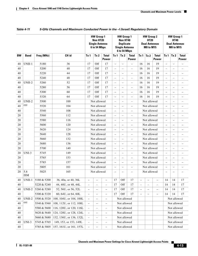
Table 4-11 5-GHz Channels and Maximum Conducted Power in the –I (Israel) Regulatory Domain
HW Group 1 Non HT20
Single Antenna6 to 54 Mbps
HW Group 1 Non HT40Duplicate
Single Antenna6 to 54 Mbps
HW Group 2HT20
Dual Antennas M0 to M15
HW Group 1 HT40
Dual AntennasM0 to M15
BW Band Freq (MHz) CH id Tx 1 Tx 2 TotalPower
Tx 1 Tx 2 TotalPower
Tx 1 Tx 2 TotalPower
Tx 1 Tx 2 TotalPower
40 UNII-1 5180 36 17 Off 17 – – – 16 16 19 – – –
40 5200 40 17 Off 17 – – – 16 16 19 – – –
40 5220 44 17 Off 17 – – – 16 16 19 – – –
40 5240 48 17 Off 17 – – – 16 16 19 – – –
40 UNII-2 5260 52 17 Off 17 – – – 16 16 19 – – –
40 5280 56 17 Off 17 – – – 16 16 19 – – –
40 5300 60 17 Off 17 – – – 16 16 19 – – –
40 5320 64 17 Off 17 – – – 16 16 19 – – –
40 UNII-2 ext
5500 100 Not allowed – – – Not allowed – – –
40 5520 104 Not allowed – – – Not allowed – – –
40 5540 108 Not allowed – – – Not allowed – – –
20 5560 112 Not allowed – – – Not allowed – – –
20 5580 116 Not allowed – – – Not allowed – – –
20 5600 120 Not allowed – – – Not allowed – – –
20 5620 124 Not allowed – – – Not allowed – – –
20 5640 128 Not allowed – – – Not allowed – – –
20 5660 132 Not allowed – – – Not allowed – – –
20 5680 136 Not allowed – – – Not allowed – – –
20 5700 140 Not allowed – – – Not allowed – – –
20 UNI-3 5745 149 Not allowed – – – Not allowed – – –
20 5765 153 Not allowed – – – Not allowed – – –
20 5785 157 Not allowed – – – Not allowed – – –
20 5805 161 Not allowed – – – Not allowed – – –
20 5.8 ISM
5825 165 Not allowed – – – Not allowed – – –
40 UNII-1 5180 & 5200 36, 40u, or 40, 36L – – – 17 Off 17 – – – 14 14 17
40 5220 & 5240 44, 48U, or 48, 44L – – – 17 Off 17 – – – 14 14 17
40 UNII-2 5260 & 5280 52, 56U, or 56, 52L – – – 17 Off 17 – – – 14 14 17
40 5300 & 5320 60, 64U, or 64, 60L – – – 17 Off 17 – – – 14 14 17
40 UNII-2 ext
5500 & 5520 100, 104U, or 104, 100L – – – Not allowed Not allowed
40 5540 & 5560 108, 112U, or 112, 108L – – – Not allowed Not allowed
40 5580 & 5600 116, 120U, or 120, 116L – – – Not allowed Not allowed
40 5620 & 5640 124, 128U, or 128, 124L – – – Not allowed Not allowed
40 5660 & 5680 132, 136U, or 136, 132L – – – Not allowed Not allowed
40 UNI-3 5745 & 5765 149, 153, or 153, 149L – – – Not allowed Not allowed
40 5785 & 5805 157, 161U, or 161, 157L – – – Not allowed Not allowed
4-13Channels and Maximum Power Settings for Cisco Aironet Lightweight Access Points
OL-11321-08
Chapter 4 Cisco Aironet 1040 and 1140 Series Lightweight Access Points Channels and Maximum Power Levels
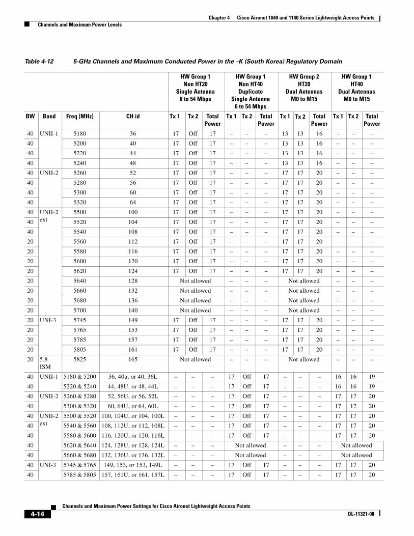
Table 4-12 5-GHz Channels and Maximum Conducted Power in the –K (South Korea) Regulatory Domain
HW Group 1 Non HT20
Single Antenna6 to 54 Mbps
HW Group 1 Non HT40Duplicate
Single Antenna6 to 54 Mbps
HW Group 2HT20
Dual Antennas M0 to M15
HW Group 1 HT40
Dual AntennasM0 to M15
BW Band Freq (MHz) CH id Tx 1 Tx 2 TotalPower
Tx 1 Tx 2 TotalPower
Tx 1 Tx 2 TotalPower
Tx 1 Tx 2 TotalPower
40 UNII-1 5180 36 17 Off 17 – – – 13 13 16 – – –
40 5200 40 17 Off 17 – – – 13 13 16 – – –
40 5220 44 17 Off 17 – – – 13 13 16 – – –
40 5240 48 17 Off 17 – – – 13 13 16 – – –
40 UNII-2 5260 52 17 Off 17 – – – 17 17 20 – – –
40 5280 56 17 Off 17 – – – 17 17 20 – – –
40 5300 60 17 Off 17 – – – 17 17 20 – – –
40 5320 64 17 Off 17 – – – 17 17 20 – – –
40 UNII-2 ext
5500 100 17 Off 17 – – – 17 17 20 – – –
40 5520 104 17 Off 17 – – – 17 17 20 – – –
40 5540 108 17 Off 17 – – – 17 17 20 – – –
20 5560 112 17 Off 17 – – – 17 17 20 – – –
20 5580 116 17 Off 17 – – – 17 17 20 – – –
20 5600 120 17 Off 17 – – – 17 17 20 – – –
20 5620 124 17 Off 17 – – – 17 17 20 – – –
20 5640 128 Not allowed – – – Not allowed – – –
20 5660 132 Not allowed – – – Not allowed – – –
20 5680 136 Not allowed – – – Not allowed – – –
20 5700 140 Not allowed – – – Not allowed – – –
20 UNI-3 5745 149 17 Off 17 – – – 17 17 20 – – –
20 5765 153 17 Off 17 – – – 17 17 20 – – –
20 5785 157 17 Off 17 – – – 17 17 20 – – –
20 5805 161 17 Off 17 – – – 17 17 20 – – –
20 5.8 ISM
5825 165 Not allowed – – – Not allowed – – –
40 UNII-1 5180 & 5200 36, 40u, or 40, 36L – – – 17 Off 17 – – – 16 16 19
40 5220 & 5240 44, 48U, or 48, 44L – – – 17 Off 17 – – – 16 16 19
40 UNII-2 5260 & 5280 52, 56U, or 56, 52L – – – 17 Off 17 – – – 17 17 20
40 5300 & 5320 60, 64U, or 64, 60L – – – 17 Off 17 – – – 17 17 20
40 UNII-2 ext
5500 & 5520 100, 104U, or 104, 100L – – – 17 Off 17 – – – 17 17 20
40 5540 & 5560 108, 112U, or 112, 108L – – – 17 Off 17 – – – 17 17 20
40 5580 & 5600 116, 120U, or 120, 116L – – – 17 Off 17 – – – 17 17 20
40 5620 & 5640 124, 128U, or 128, 124L – – – Not allowed – – – Not allowed
40 5660 & 5680 132, 136U, or 136, 132L – – – Not allowed – – – Not allowed
40 UNI-3 5745 & 5765 149, 153, or 153, 149L – – – 17 Off 17 – – – 17 17 20
40 5785 & 5805 157, 161U, or 161, 157L – – – 17 Off 17 – – – 17 17 20
4-14Channels and Maximum Power Settings for Cisco Aironet Lightweight Access Points
OL-11321-08

Chapter 4 Cisco Aironet 1040 and 1140 Series Lightweight Access Points Channels and Maximum Power Levels
Table 4-13 5-GHz Channels and Maximum Conducted Power in the –N (Non FCC) Regulatory Domain
HW Group 1 Non HT20
Single Antenna6 to 54 Mbps
HW Group 1 Non HT40Duplicate
Single Antenna6 to 54 Mbps
HW Group 2HT20
Dual Antennas M0 to M15
HW Group 1 HT40
Dual AntennasM0 to M15
BW Band Freq (MHz) CH id Tx 1 Tx 2 TotalPower
Tx 1 Tx 2 TotalPower
Tx 1
Tx 2 TotalPower
Tx 1 Tx 2 TotalPower
40 UNII-1 5180 36 14 Off 14 – – – 11 11 14 – – –
40 5200 40 14 Off 14 – – – 11 11 14 – – –
40 5220 44 14 Off 14 – – – 11 11 14 – – –
40 5240 48 14 Off 14 – – – 11 11 14 – – –
40 UNII-2 5260 52 17 Off 17 – – – 17 17 20 – – –
40 5280 56 17 Off 17 – – – 17 17 20 – – –
40 5300 60 17 Off 17 – – – 17 17 20 – – –
40 5320 64 17 Off 17 – – – 16 16 19 – – –
40 UNII-2 ext
5500 100 Not allowed – – – Not allowed – – –
40 5520 104 Not allowed – – – Not allowed – – –
40 5540 108 Not allowed – – – Not allowed – – –
20 5560 112 Not allowed – – – Not allowed – – –
20 5580 116 Not allowed – – – Not allowed – – –
20 5600 120 Not allowed – – – Not allowed – – –
20 5620 124 Not allowed – – – Not allowed – – –
20 5640 128 Not allowed – – – Not allowed – – –
20 5660 132 Not allowed – – – Not allowed – – –
20 5680 136 Not allowed – – – Not allowed – – –
20 5700 140 Not allowed – – – Not allowed – – –
20 UNI-3 5745 149 17 Off 17 – – – 17 17 20 – – –
20 5765 153 17 Off 17 – – – 17 17 20 – – –
20 5785 157 17 Off 17 – – – 17 17 20 – – –
20 5805 161 17 Off 17 – – – 17 17 20 – – –
20 5.8 ISM
5825 165 17 Off 17 – – – 17 17 20 – – –
40 UNII-1 5180 & 5200 36, 40u, or 40, 36L – – – 17 Off 17 – – – 14 14 17
40 5220 & 5240 44, 48U, or 48, 44L – – – 17 Off 17 – – – 14 14 17
40 UNII-2 5260 & 5280 52, 56U, or 56, 52L – – – 17 Off 17 – – – 17 17 20
40 5300 & 5320 60, 64U, or 64, 60L – – – 17 Off 17 – – – 14 14 17
40 UNII-2 ext
5500 & 5520 100, 104U, or 104, 100L – – – Not allowed – – – Not allowed
40 5540 & 5560 108, 112U, or 112, 108L – – – Not allowed – – – Not allowed
40 5580 & 5600 116, 120U, or 120, 116L – – – Not allowed – – – Not allowed
40 5620 & 5640 124, 128U, or 128, 124L – – – Not allowed – – – Not allowed
40 5660 & 5680 132, 136U, or 136, 132L – – – Not allowed – – – Not allowed
40 UNI-3 5745 & 5765 149, 153, or 153, 149L – – – 17 Off 17 – – – 17 17 20
40 5785 & 5805 157, 161U, or 161, 157L – – – 17 Off 17 – – – 17 17 20
4-15Channels and Maximum Power Settings for Cisco Aironet Lightweight Access Points
OL-11321-08
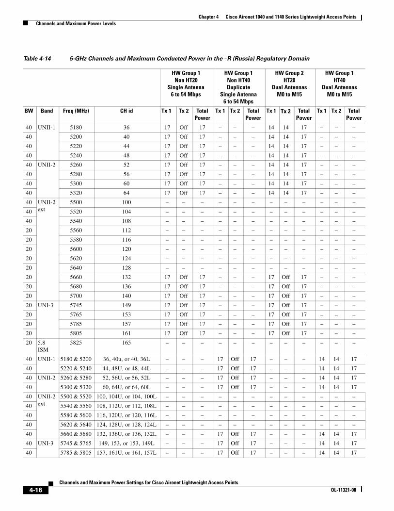
Chapter 4 Cisco Aironet 1040 and 1140 Series Lightweight Access Points Channels and Maximum Power Levels
Table 4-14 5-GHz Channels and Maximum Conducted Power in the –R (Russia) Regulatory Domain
HW Group 1 Non HT20
Single Antenna6 to 54 Mbps
HW Group 1 Non HT40Duplicate
Single Antenna6 to 54 Mbps
HW Group 2HT20
Dual Antennas M0 to M15
HW Group 1 HT40
Dual AntennasM0 to M15
BW Band Freq (MHz) CH id Tx 1 Tx 2 TotalPower
Tx 1 Tx 2 TotalPower
Tx 1 Tx 2 TotalPower
Tx 1 Tx 2 TotalPower
40 UNII-1 5180 36 17 Off 17 – – – 14 14 17 – – –
40 5200 40 17 Off 17 – – – 14 14 17 – – –
40 5220 44 17 Off 17 – – – 14 14 17 – – –
40 5240 48 17 Off 17 – – – 14 14 17 – – –
40 UNII-2 5260 52 17 Off 17 – – – 14 14 17 – – –
40 5280 56 17 Off 17 – – – 14 14 17 – – –
40 5300 60 17 Off 17 – – – 14 14 17 – – –
40 5320 64 17 Off 17 – – – 14 14 17 – – –
40 UNII-2 ext
5500 100 – – – – – – – – – – – –
40 5520 104 – – – – – – – – – – – –
40 5540 108 – – – – – – – – – – – –
20 5560 112 – – – – – – – – – – – –
20 5580 116 – – – – – – – – – – – –
20 5600 120 – – – – – – – – – – – –
20 5620 124 – – – – – – – – – – – –
20 5640 128 – – – – – – – – – – – –
20 5660 132 17 Off 17 – – – 17 Off 17 – – –
20 5680 136 17 Off 17 – – – 17 Off 17 – – –
20 5700 140 17 Off 17 – – – 17 Off 17 – – –
20 UNI-3 5745 149 17 Off 17 – – – 17 Off 17 – – –
20 5765 153 17 Off 17 – – – 17 Off 17 – – –
20 5785 157 17 Off 17 – – – 17 Off 17 – – –
20 5805 161 17 Off 17 – – – 17 Off 17 – – –
20 5.8 ISM
5825 165 – – – – – – – – – – – –
40 UNII-1 5180 & 5200 36, 40u, or 40, 36L – – – 17 Off 17 – – – 14 14 17
40 5220 & 5240 44, 48U, or 48, 44L – – – 17 Off 17 – – – 14 14 17
40 UNII-2 5260 & 5280 52, 56U, or 56, 52L – – – 17 Off 17 – – – 14 14 17
40 5300 & 5320 60, 64U, or 64, 60L – – – 17 Off 17 – – – 14 14 17
40 UNII-2 ext
5500 & 5520 100, 104U, or 104, 100L – – – – – – – – – – – –
40 5540 & 5560 108, 112U, or 112, 108L – – – – – – – – – – – –
40 5580 & 5600 116, 120U, or 120, 116L – – – – – – – – – – – –
40 5620 & 5640 124, 128U, or 128, 124L – – – – – – – – – – – –
40 5660 & 5680 132, 136U, or 136, 132L – – – 17 Off 17 – – – 14 14 17
40 UNI-3 5745 & 5765 149, 153, or 153, 149L – – – 17 Off 17 – – – 14 14 17
40 5785 & 5805 157, 161U, or 161, 157L – – – 17 Off 17 – – – 14 14 17
4-16Channels and Maximum Power Settings for Cisco Aironet Lightweight Access Points
OL-11321-08
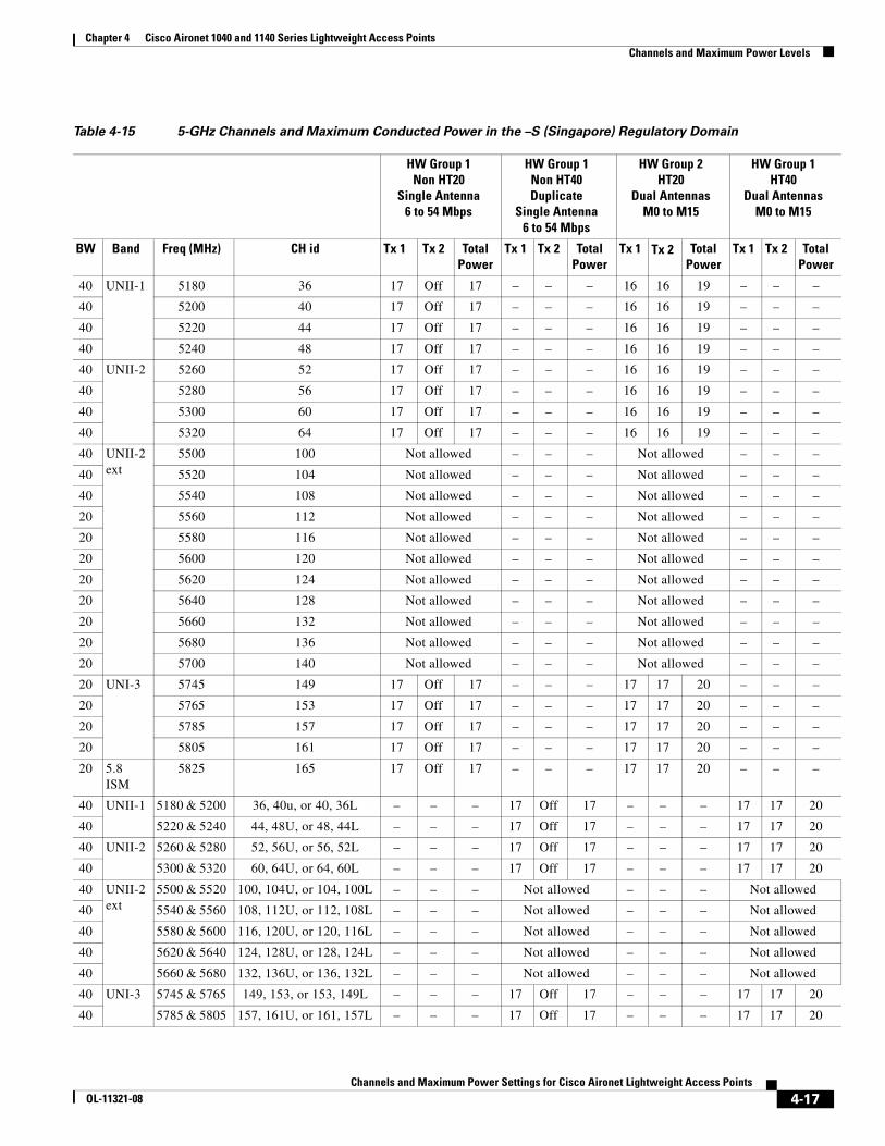
Chapter 4 Cisco Aironet 1040 and 1140 Series Lightweight Access Points Channels and Maximum Power Levels
Table 4-15 5-GHz Channels and Maximum Conducted Power in the –S (Singapore) Regulatory Domain
HW Group 1 Non HT20
Single Antenna6 to 54 Mbps
HW Group 1 Non HT40Duplicate
Single Antenna6 to 54 Mbps
HW Group 2HT20
Dual Antennas M0 to M15
HW Group 1 HT40
Dual AntennasM0 to M15
BW Band Freq (MHz) CH id Tx 1 Tx 2 TotalPower
Tx 1 Tx 2 TotalPower
Tx 1 Tx 2 TotalPower
Tx 1 Tx 2 TotalPower
40 UNII-1 5180 36 17 Off 17 – – – 16 16 19 – – –
40 5200 40 17 Off 17 – – – 16 16 19 – – –
40 5220 44 17 Off 17 – – – 16 16 19 – – –
40 5240 48 17 Off 17 – – – 16 16 19 – – –
40 UNII-2 5260 52 17 Off 17 – – – 16 16 19 – – –
40 5280 56 17 Off 17 – – – 16 16 19 – – –
40 5300 60 17 Off 17 – – – 16 16 19 – – –
40 5320 64 17 Off 17 – – – 16 16 19 – – –
40 UNII-2 ext
5500 100 Not allowed – – – Not allowed – – –
40 5520 104 Not allowed – – – Not allowed – – –
40 5540 108 Not allowed – – – Not allowed – – –
20 5560 112 Not allowed – – – Not allowed – – –
20 5580 116 Not allowed – – – Not allowed – – –
20 5600 120 Not allowed – – – Not allowed – – –
20 5620 124 Not allowed – – – Not allowed – – –
20 5640 128 Not allowed – – – Not allowed – – –
20 5660 132 Not allowed – – – Not allowed – – –
20 5680 136 Not allowed – – – Not allowed – – –
20 5700 140 Not allowed – – – Not allowed – – –
20 UNI-3 5745 149 17 Off 17 – – – 17 17 20 – – –
20 5765 153 17 Off 17 – – – 17 17 20 – – –
20 5785 157 17 Off 17 – – – 17 17 20 – – –
20 5805 161 17 Off 17 – – – 17 17 20 – – –
20 5.8 ISM
5825 165 17 Off 17 – – – 17 17 20 – – –
40 UNII-1 5180 & 5200 36, 40u, or 40, 36L – – – 17 Off 17 – – – 17 17 20
40 5220 & 5240 44, 48U, or 48, 44L – – – 17 Off 17 – – – 17 17 20
40 UNII-2 5260 & 5280 52, 56U, or 56, 52L – – – 17 Off 17 – – – 17 17 20
40 5300 & 5320 60, 64U, or 64, 60L – – – 17 Off 17 – – – 17 17 20
40 UNII-2 ext
5500 & 5520 100, 104U, or 104, 100L – – – Not allowed – – – Not allowed
40 5540 & 5560 108, 112U, or 112, 108L – – – Not allowed – – – Not allowed
40 5580 & 5600 116, 120U, or 120, 116L – – – Not allowed – – – Not allowed
40 5620 & 5640 124, 128U, or 128, 124L – – – Not allowed – – – Not allowed
40 5660 & 5680 132, 136U, or 136, 132L – – – Not allowed – – – Not allowed
40 UNI-3 5745 & 5765 149, 153, or 153, 149L – – – 17 Off 17 – – – 17 17 20
40 5785 & 5805 157, 161U, or 161, 157L – – – 17 Off 17 – – – 17 17 20
4-17Channels and Maximum Power Settings for Cisco Aironet Lightweight Access Points
OL-11321-08

Chapter 4 Cisco Aironet 1040 and 1140 Series Lightweight Access Points Channels and Maximum Power Levels
Table 4-16 5-GHz Channels and Maximum Conducted Power in the –T (Taiwan) Regulatory Domain
HW Group 1 Non HT20
Single Antenna6 to 54 Mbps
HW Group 1 Non HT40Duplicate
Single Antenna6 to 54 Mbps
HW Group 2HT20
Dual Antennas M0 to M15
HW Group 1 HT40
Dual AntennasM0 to M15
BW Band Freq (MHz) CH id Tx 1 Tx 2 TotalPower
Tx 1 Tx 2 TotalPower
Tx 1 Tx 2 TotalPower
Tx 1 Tx 2 TotalPower
40 UNII-1 5180 36 Not allowed – – – Not allowed – – –
40 5200 40 Not allowed – – – Not allowed – – –
40 5220 44 Not allowed – – – Not allowed – – –
40 5240 48 Not allowed – – – Not allowed – – –
40 UNII-2 5260 52 Not allowed – – – Not allowed – – –
40 5280 56 15 Off 15 – – – 11 11 14 – – –
40 5300 60 15 Off 15 – – – 11 11 14 – – –
40 5320 64 15 Off 15 – – – 11 11 14 – – –
40 UNII-2 ext
5500 100 17 Off 17 – – – 17 17 20 – – –
40 5520 104 17 Off 17 – – – 17 17 20 – – –
40 5540 108 17 Off 17 – – – 17 17 20 – – –
20 5560 112 17 Off 17 – – – 17 17 20 – – –
20 5580 116 17 Off 17 – – – 17 17 20 – – –
20 5600 120 17 Off 17 – – – 17 17 20 – – –
20 5620 124 17 Off 17 – – – 17 17 20 – – –
20 5640 128 17 Off 17 – – – 17 17 20 – – –
20 5660 132 17 Off 17 – – – 17 17 20 – – –
20 5680 136 17 Off 17 – – – 17 17 20 – – –
20 5700 140 17 Off 17 – – – 17 17 20 – – –
20 UNI-3 5745 149 17 Off 17 – – – 17 17 20 – – –
20 5765 153 17 Off 17 – – – 17 17 20 – – –
20 5785 157 17 Off 17 – – – 17 17 20 – – –
20 5805 161 17 Off 17 – – – 17 17 20 – – –
20 5.8 ISM
5825 165 17 Off 17 – – – 17 17 20 – – –
40 UNII-1 5180 & 5200 36, 40u, or 40, 36L – – – Not allowed Not allowed
40 5220 & 5240 44, 48U, or 48, 44L – – – Not allowed Not allowed
40 UNII-2 5260 & 5280 52, 56U, or 56, 52L – – – Not allowed Not allowed
40 5300 & 5320 60, 64U, or 64, 60L – – – 14 Off 14 14 14 17
40 UNII-2 ext
5500 & 5520 100, 104U, or 104, 100L – – – 17 Off 17 14 14 17
40 5540 & 5560 108, 112U, or 112, 108L – – – 17 Off 17 17 17 20
40 5580 & 5600 116, 120U, or 120, 116L – – – 17 Off 17 17 17 20
40 5620 & 5640 124, 128U, or 128, 124L – – – 17 Off 17 17 17 20
40 5660 & 5680 132, 136U, or 136, 132L – – – 17 Off 17 17 17 20
40 UNI-3 5745 & 5765 149, 153, or 153, 149L – – – 17 Off 17 17 17 20
40 5785 & 5805 157, 161U, or 161, 157L – – – 17 Off 17 17 17 20
4-18Channels and Maximum Power Settings for Cisco Aironet Lightweight Access Points
OL-11321-08
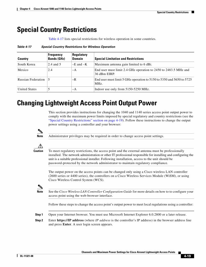
Chapter 4 Cisco Aironet 1040 and 1140 Series Lightweight Access Points Special Country Restrictions
Special Country RestrictionsTable 4-17 lists special restrictions for wireless operation in some countries.
Changing Lightweight Access Point Output PowerThis section provides instructions for changing the 1040 and 1140 series access point output power to comply with the maximum power limits imposed by special regulatory and country restrictions (see the “Special Country Restrictions” section on page 4-19). Follow these instructions to change the output power settings using a controller and your browser:
Note Administrator privileges may be required in order to change access point settings.
Caution To meet regulatory restrictions, the access point and the external antenna must be professionally installed. The network administration or other IT professional responsible for installing and configuring the unit is a suitable professional installer. Following installation, access to the unit should be password-protected by the network administrator to maintain regulatory compliance.
The output power on the access points can be changed only using a Cisco wireless LAN controller(2600 series or 4400 series), the controllers on a Cisco Wireless Services Module (WiSM), or using Cisco Wireless Control System (WCS).
Note See the Cisco Wireless LAN Controller Configuration Guide for more details on how to to configure your access point using the web-browser interface.
Follow these steps to change the access point’s output power to meet local regulations using a controller:
Step 1 Open your Internet browser. You must use Microsoft Internet Explorer 6.0.2800 or a later release.
Step 2 Enter https://IP address (where IP address is the controller’s IP address) in the browser address line and press Enter. A user login screen appears.
Table 4-17 Special Country Restrictions for Wireless Operation
CountryFrequency Bands (GHz)
Regulatory Domain Special Limitation and Restrictions
South Korea 2.4 and 5 –E and –K Maximum antenna gain limited to 6 dBi.
Mexico 2.4 –A End user must limit 2.4 GHz operation to 2450 to 2483.5 MHz and 36 dBm EIRP.
Russian Federation 5 –R End user must limit 5 GHz operation to 5150 to 5350 and 5650 to 5725 MHz.
United States 5 –A Indoor use only from 5150-5250 MHz.
4-19Channels and Maximum Power Settings for Cisco Aironet Lightweight Access Points
OL-11321-08
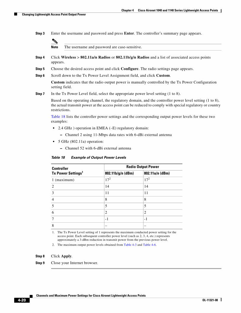
Chapter 4 Cisco Aironet 1040 and 1140 Series Lightweight Access Points Changing Lightweight Access Point Output Power
Step 3 Enter the username and password and press Enter. The controller’s summary page appears.
Note The username and password are case-sensitive.
Step 4 Click Wireless > 802.11a/n Radios or 802.11b/g/n Radios and a list of associated access points appears.
Step 5 Choose the desired access point and click Configure. The radio settings page appears.
Step 6 Scroll down to the Tx Power Level Assignment field, and click Custom.
Custom indicates that the radio output power is manually controlled by the Tx Power Configuration setting field.
Step 7 In the Tx Power Level field, select the appropriate power level setting (1 to 8).
Based on the operating channel, the regulatory domain, and the controller power level setting (1 to 8), the actual transmit power at the access point can be reduced to comply with special regulatory or country restrictions.
Table 18 lists the controller power settings and the corresponding output power levels for these two examples:
• 2.4 GHz ) operation in EMEA (–E) regulatory domain:
– Channel 2 using 11-Mbps data rates with 6-dBi external antenna
• 5 GHz (802.11a) operation:
– Channel 52 with 6-dBi external antenna
Step 8 Click Apply.
Step 9 Close your Internet browser.
Table 18 Example of Output Power Levels
Controller Tx Power Settings1
1. The Tx Power Level setting of 1 represents the maximum conducted power setting for the access point. Each subsequent controller power level (such as 2, 3, 4, etc.) represents approximately a 3-dBm reduction in transmit power from the previous power level.
Radio Output Power
802.11b/g/n (dBm) 802.11a/n (dBm)
1 (maximum) 172
2. The maximum output power levels obtained from Table 4-3 and Table 4-6.
172
2 14 14
3 11 11
4 8 8
5 5 5
6 2 2
7 -1 -1
8 – –
4-20Channels and Maximum Power Settings for Cisco Aironet Lightweight Access Points
OL-11321-08

Channels and Maximum Power SeOL-11321-08
C H A P T E R 5
Cisco Aironet 1200 Series Access PointsThis section lists the 1200 series lightweight access point (models: AIR-LAP1231G and AIR-LAP1232AG) IEEE 802.11g (2.4-GHz) and IEEE 802.11a (5-GHz) channels, maximum power levels, and antenna gains supported by the world’s regulatory domains. For additional product hardware information refer to the Cisco Aironet 1200 Series Access Point Hardware Installation Guide.
The following topics are covered in this section:
• Channels, page 5-2
• Maximum Power Levels and Antenna Gains, page 5-4
• Power Conversion Table, page 5-9
• Changing the Lightweight Access Point Output Power, page 5-10
5-1ttings for Cisco Aironet Lightweight Access Points
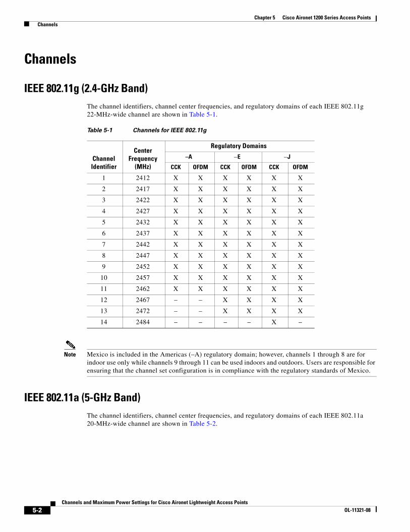
Chapter 5 Cisco Aironet 1200 Series Access Points Channels
Channels
IEEE 802.11g (2.4-GHz Band)The channel identifiers, channel center frequencies, and regulatory domains of each IEEE 802.11g 22-MHz-wide channel are shown in Table 5-1.
Note Mexico is included in the Americas (–A) regulatory domain; however, channels 1 through 8 are for indoor use only while channels 9 through 11 can be used indoors and outdoors. Users are responsible for ensuring that the channel set configuration is in compliance with the regulatory standards of Mexico.
IEEE 802.11a (5-GHz Band)The channel identifiers, channel center frequencies, and regulatory domains of each IEEE 802.11a 20-MHz-wide channel are shown in Table 5-2.
Table 5-1 Channels for IEEE 802.11g
Channel Identifier
Center Frequency
(MHz)
Regulatory Domains
–A –E –J
CCK OFDM CCK OFDM CCK OFDM
1 2412 X X X X X X
2 2417 X X X X X X
3 2422 X X X X X X
4 2427 X X X X X X
5 2432 X X X X X X
6 2437 X X X X X X
7 2442 X X X X X X
8 2447 X X X X X X
9 2452 X X X X X X
10 2457 X X X X X X
11 2462 X X X X X X
12 2467 – – X X X X
13 2472 – – X X X X
14 2484 – – – – X –
5-2Channels and Maximum Power Settings for Cisco Aironet Lightweight Access Points
OL-11321-08
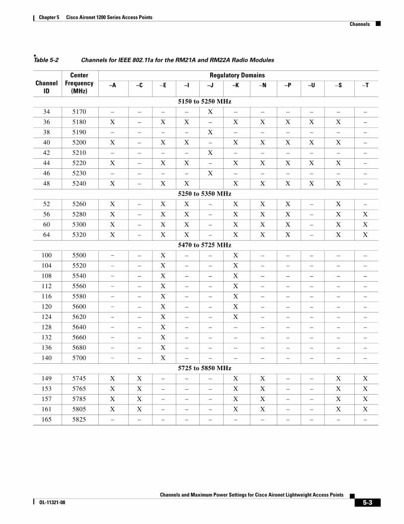
Chapter 5 Cisco Aironet 1200 Series Access Points Channels
..Table 5-2 Channels for IEEE 802.11a for the RM21A and RM22A Radio Modules
Channel ID
Center Frequency
(MHz)
Regulatory Domains–A –C –E –I –J –K –N –P –U –S –T
5150 to 5250 MHz
34 5170 – – – – X – – – – – –
36 5180 X – X X – X X X X X –
38 5190 – – – – X – – – – – –
40 5200 X – X X – X X X X X –
42 5210 – – – – X – – – – – –
44 5220 X – X X – X X X X X –
46 5230 – – – – X – – – – – –
48 5240 X – X X X X X X X –
5250 to 5350 MHz
52 5260 X – X X – X X X – X –
56 5280 X – X X – X X X – X X
60 5300 X – X X – X X X – X X
64 5320 X – X X – X X X – X X
5470 to 5725 MHz
100 5500 – – X – – X – – – – –
104 5520 – – X – – X – – – – –
108 5540 – – X – – X – – – – –
112 5560 – – X – – X – – – – –
116 5580 – – X – – X – – – – –
120 5600 – – X – – X – – – – –
124 5620 – – X – – X – – – – –
128 5640 – – X – – – – – – – –
132 5660 – – X – – – – – – – –
136 5680 – – X – – – – – – – –
140 5700 – – X – – – – – – – –
5725 to 5850 MHz
149 5745 X X – – – X X – – X X
153 5765 X X – – – X X – – X X
157 5785 X X – – – X X – – X X
161 5805 X X – – – X X – – X X
165 5825 – – – – – – – – – – –
5-3Channels and Maximum Power Settings for Cisco Aironet Lightweight Access Points
OL-11321-08

Chapter 5 Cisco Aironet 1200 Series Access Points Maximum Power Levels and Antenna Gains
Maximum Power Levels and Antenna Gains
IEEE 802.11g (2.4-GHz Band)An improper combination of power level and antenna gain can result in equivalent isotropic radiated power (EIRP) above the amount allowed per regulatory domain. Table 5-3 indicates the maximum power levels and antenna gains allowed for each IEEE 802.11g regulatory domain.
Table 5-3 Maximum Power Levels Per Antenna Gain for IEEE 802.11g
Regulatory Domain Antenna Gain (dBi)
Maximum Power Level (mW)
CCK Modulation OFDM Modulation
–A(4 W EIRP maximum)
2.2 100 30
5 100 30
6 100 30
6.5 100 30
8.5 100 30
10 100 30
–E(100 mW EIRP maximum)
2.2 50 30
5 30 10
6 30 10
6.5 20 10
8.5 10 5
10 10 5
–I(100 mW EIRP maximum)
2.2 50 30
5 30 10
6 30 10
6.5 20 10
8.5 10 5
10 10 5
–J(10 mW/MHz EIRP maximum)
2.2 30 30
5 30 30
6 30 30
6.5 30 30
8.5 – –
10 – –
5-4Channels and Maximum Power Settings for Cisco Aironet Lightweight Access Points
OL-11321-08
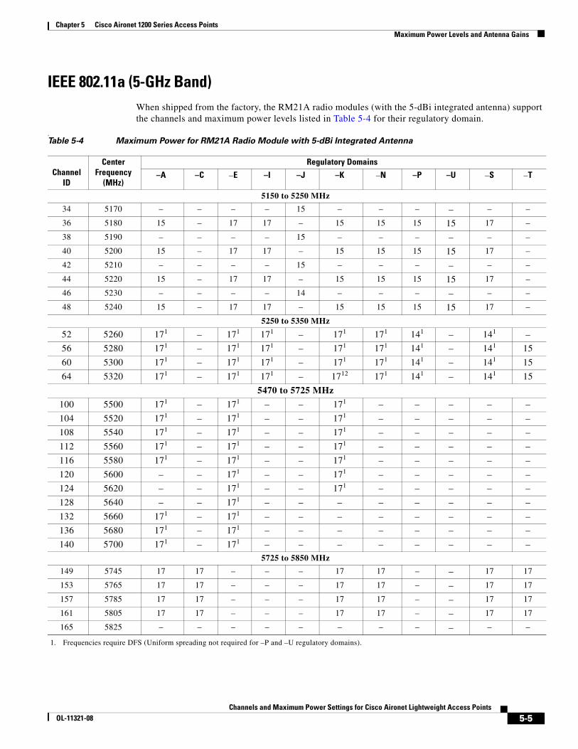
Chapter 5 Cisco Aironet 1200 Series Access Points Maximum Power Levels and Antenna Gains
IEEE 802.11a (5-GHz Band)When shipped from the factory, the RM21A radio modules (with the 5-dBi integrated antenna) support the channels and maximum power levels listed in Table 5-4 for their regulatory domain.
.Table 5-4 Maximum Power for RM21A Radio Module with 5-dBi Integrated Antenna
Channel ID
Center Frequency
(MHz)
Regulatory Domains
–A –C –E –I –J –K –N –P –U –S –T
5150 to 5250 MHz
34 5170 – – – – 15 – – – – – –
36 5180 15 – 17 17 – 15 15 15 15 17 –
38 5190 – – – – 15 – – – – – –
40 5200 15 – 17 17 – 15 15 15 15 17 –
42 5210 – – – – 15 – – – – – –
44 5220 15 – 17 17 – 15 15 15 15 17 –
46 5230 – – – – 14 – – – – – –
48 5240 15 – 17 17 – 15 15 15 15 17 –
5250 to 5350 MHz
52 5260 171
1. Frequencies require DFS (Uniform spreading not required for –P and –U regulatory domains).
– 171 171 – 171 171 141 – 141 –
56 5280 171 – 171 171 – 171 171 141 – 141 15
60 5300 171 – 171 171 – 171 171 141 – 141 15
64 5320 171 – 171 171 – 1712 171 141 – 141 15
5470 to 5725 MHz
100 5500 171 – 171 – – 171 – – – – –
104 5520 171 – 171 – – 171 – – – – –
108 5540 171 – 171 – – 171 – – – – –
112 5560 171 – 171 – – 171 – – – – –
116 5580 171 – 171 – – 171 – – – – –
120 5600 – – 171 – – 171 – – – – –
124 5620 – – 171 – – 171 – – – – –
128 5640 – – 171 – – – – – – – –
132 5660 171 – 171 – – – – – – – –
136 5680 171 – 171 – – – – – – – –
140 5700 171 – 171 – – – – – – – –
5725 to 5850 MHz
149 5745 17 17 – – – 17 17 – – 17 17
153 5765 17 17 – – – 17 17 – – 17 17
157 5785 17 17 – – – 17 17 – – 17 17
161 5805 17 17 – – – 17 17 – – 17 17
165 5825 – – – – – – – – – – –
5-5Channels and Maximum Power Settings for Cisco Aironet Lightweight Access Points
OL-11321-08

Chapter 5 Cisco Aironet 1200 Series Access Points Maximum Power Levels and Antenna Gains
When shipped from the factory, the RM21A radio modules (with the 9-dBi integrated antenna) support the channels and maximum power levels listed in Table 5-5 for their regulatory domain.
..Table 5-5 Maximum Power for RM21A Radio Module with 9-dBi Integrated Antenna
Channel ID
Center Frequency
(MHz)
Regulatory Domains–A –C –E –I –J –K –N –P –U –S –T
5150 to 5250 MHz
34 5170 – – – – 11 – – – – – –
36 5180 11 – 14 14 – 15 11 11 11 14 –
38 5190 – – – – 11 – – – – – –
40 5200 11 – 14 14 – 15 11 11 11 14 –
42 5210 – – – – 11 – – – – – –
44 5220 11 – 14 14 – 15 11 11 11 14 –
46 5230 – – – – 11 – – – – – –
48 5240 11 – 14 14 – 15 11 11 11 14 –
5250 to 5350 MHz
52 5260 171
1. Frequencies require DFS (Uniform spreading not required for the –P and –U regulatory domains).
– 141 141 – 171 171 81 – 111 –
56 5280 171 – 141 141 – 171 171 81 – 111 11
60 5300 171 – 141 141 – 171 171 81 – 111 11
64 5320 111 – 141 141 – 171 171 81 – 111 11
5470 to 5725 MHz
100 5500 171 – 171 – – 171 – – – – –
104 5520 171 – 171 – – 171 – – – – –
108 5540 171 – 171 – – 171 – – – – –
112 5560 171 – 171 – – 171 – – – – –
116 5580 171 – 171 – – 171 – – – – –
120 5600 – – 171 – – 171 – – – – –
124 5620 – – 171 – – 171 – – – – –
128 5640 – – 171 – – – – – – – –
132 5660 171 – 171 – – – – – – – –
136 5680 171 – 171 – – – – – – – –
140 5700 171 – 171 – – – – – – – –
5725 to 5850 MHz
149 5745 17 17 – – – 17 17 – – 17 17
153 5765 17 17 – – – 17 17 – – 17 17
157 5785 14 17 – – – 17 14 – – 17 14
161 5805 11 17 – – – 17 11 – – 17 11
165 5825 – – – – – – – – – – –
5-6Channels and Maximum Power Settings for Cisco Aironet Lightweight Access Points
OL-11321-08
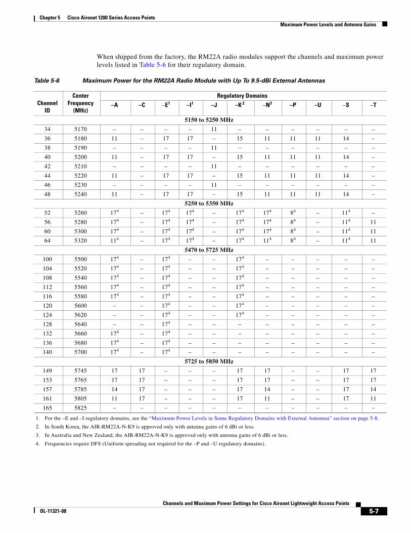
Chapter 5 Cisco Aironet 1200 Series Access Points Maximum Power Levels and Antenna Gains
When shipped from the factory, the RM22A radio modules support the channels and maximum power levels listed in Table 5-6 for their regulatory domain.
.Table 5-6 Maximum Power for the RM22A Radio Module with Up To 9.5-dBi External Antennas
Channel ID
Center Frequency
(MHz)
Regulatory Domains
–A –C –E1
1. For the –E and –I regulatory domains, see the “Maximum Power Levels in Some Regulatory Domains with External Antennas” section on page 5-8.
–I1 –J –K,2
2. In South Korea, the AIR-RM22A-N-K9 is approved only with antenna gains of 6 dBi or less.
–N3
3. In Australia and New Zealand, the AIR-RM22A-N-K9 is approved only with antenna gains of 6 dBi or less.
–P –U –S –T
5150 to 5250 MHz
34 5170 – – – – 11 – – – – – –
36 5180 11 – 17 17 – 15 11 11 11 14 –
38 5190 – – – – 11 – – – – – –
40 5200 11 – 17 17 – 15 11 11 11 14 –
42 5210 – – – – 11 – – – – – –
44 5220 11 – 17 17 – 15 11 11 11 14 –
46 5230 – – – – 11 – – – – – –
48 5240 11 – 17 17 – 15 11 11 11 14 –
5250 to 5350 MHz
52 5260 174
4. Frequencies require DFS (Uniform spreading not required for the –P and –U regulatory domains).
– 174 174 – 174 174 84 – 114 –
56 5280 174 – 174 174 – 174 174 84 – 114 11
60 5300 174 – 174 174 – 174 174 84 – 114 11
64 5320 114 – 174 174 – 174 114 84 – 114 11
5470 to 5725 MHz
100 5500 174 – 174 – – 174 – – – – –
104 5520 174 – 174 – – 174 – – – – –
108 5540 174 – 174 – – 174 – – – – –
112 5560 174 – 174 – – 174 – – – – –
116 5580 174 – 174 – – 174 – – – – –
120 5600 – – 174 – – 174 – – – – –
124 5620 – – 174 – – 174 – – – – –
128 5640 – – 174 – – – – – – – –
132 5660 174 – 174 – – – – – – – –
136 5680 174 – 174 – – – – – – – –
140 5700 174 – 174 – – – – – – – –
5725 to 5850 MHz
149 5745 17 17 – – – 17 17 – – 17 17
153 5765 17 17 – – – 17 17 – – 17 17
157 5785 14 17 – – – 17 14 – – 17 14
161 5805 11 17 – – – 17 11 – – 17 11
165 5825 – – – – – – – – – – –
5-7Channels and Maximum Power Settings for Cisco Aironet Lightweight Access Points
OL-11321-08
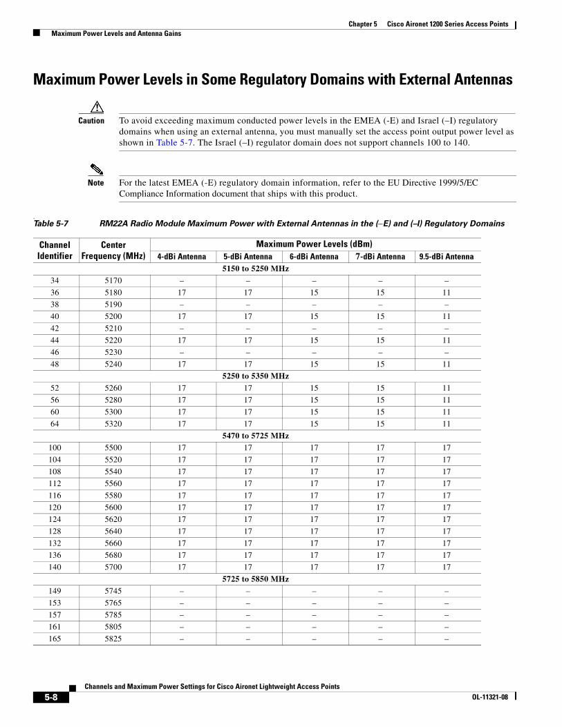
Chapter 5 Cisco Aironet 1200 Series Access Points Maximum Power Levels and Antenna Gains
Maximum Power Levels in Some Regulatory Domains with External Antennas
Caution To avoid exceeding maximum conducted power levels in the EMEA (-E) and Israel (–I) regulatory domains when using an external antenna, you must manually set the access point output power level as shown in Table 5-7. The Israel (–I) regulator domain does not support channels 100 to 140.
Note For the latest EMEA (-E) regulatory domain information, refer to the EU Directive 1999/5/EC Compliance Information document that ships with this product.
.Table 5-7 RM22A Radio Module Maximum Power with External Antennas in the (–E) and (–I) Regulatory Domains
Channel Identifier
Center Frequency (MHz)
Maximum Power Levels (dBm) 4-dBi Antenna 5-dBi Antenna 6-dBi Antenna 7-dBi Antenna 9.5-dBi Antenna
5150 to 5250 MHz
34 5170 – – – – –
36 5180 17 17 15 15 11
38 5190 – – – – –
40 5200 17 17 15 15 11
42 5210 – – – – –
44 5220 17 17 15 15 11
46 5230 – – – – –
48 5240 17 17 15 15 11
5250 to 5350 MHz
52 5260 17 17 15 15 11
56 5280 17 17 15 15 11
60 5300 17 17 15 15 11
64 5320 17 17 15 15 11
5470 to 5725 MHz100 5500 17 17 17 17 17
104 5520 17 17 17 17 17
108 5540 17 17 17 17 17
112 5560 17 17 17 17 17
116 5580 17 17 17 17 17
120 5600 17 17 17 17 17
124 5620 17 17 17 17 17
128 5640 17 17 17 17 17
132 5660 17 17 17 17 17
136 5680 17 17 17 17 17
140 5700 17 17 17 17 17
5725 to 5850 MHz149 5745 – – – – –
153 5765 – – – – –
157 5785 – – – – –
161 5805 – – – – –
165 5825 – – – – –
5-8Channels and Maximum Power Settings for Cisco Aironet Lightweight Access Points
OL-11321-08

Chapter 5 Cisco Aironet 1200 Series Access Points Power Conversion Table
Special Country RestrictionsTable 5-8 lists special restrictions for wireless operation in some countries.
Power Conversion TableYou can use Table 5-9 to convert power values from dBm to mW or from mW to dBm.
Table 5-8 Special Country Restrictions for Wireless Operation
CountryFrequency Band (GHz)
Regulatory Domain Special Limitation and Restrictions
Australia andNew Zealand
5 –N 2.4 and 5 GHz external antenna gain limited to 6 dBi. or less
South Korea 2.4 and 5 –K 2.4 and 5 GHz external antenna gain limited to 6 dBi or less.
Mexico 2.4 –N End user must limit 2.4 GHz operation to 2450 to 2483.5 MHz and36 dBm EIRP1.
1. EIRP (dBm) = maximum output power (dBm) + antenna gain (dBi)
Russian Federation 5 –E End user must limit 5 GHz operation to 5150 to 5350 and 5650 to 5725 MHz.
United States 2.4 –A Operation limited to indoor use only from 5150-5250 MHz.
Table 5-9 Power Conversion Table
mW dBm mW dBm
200 23 15 12
150 22 12 11
125 21 10 10
100 20 8 9
80 19 6 8
60 18 5 7
50 17 4 6
40 16 3 5
30 15 2 2
25 14 1 –1
20 13 –
5-9Channels and Maximum Power Settings for Cisco Aironet Lightweight Access Points
OL-11321-08

Chapter 5 Cisco Aironet 1200 Series Access Points Changing the Lightweight Access Point Output Power
Changing the Lightweight Access Point Output PowerThis section provides instructions for changing the 1200 series access point output power to comply with the maximum power limits imposed by special regulatory and country restrictions (see the“Maximum Power Levels in Some Regulatory Domains with External Antennas” section on page 5-8 and the “Special Country Restrictions” section on page 5-9). Follow these instructions to change the output power settings using a controller and your browser:
Note Administrator privileges may be required in order to change access point settings.
Note Regulatory domains are set at the factory and cannot be changed by the user.
Caution To meet regulatory restrictions, the access point and the external antenna must be professionally installed. The network administration or other IT professional responsible for installing and configuring the unit is a suitable professional installer. Following installation, access to the unit should be password protected by the network administrator to maintain regulatory compliance.
The output power on the access points can be changed only using a Cisco wireless LAN controller (2600 series or 4400 series), the controllers on a Cisco Wireless Services Module (WiSM), or using Cisco Wireless Control System (WCS).
Note See the Cisco Wireless LAN Controller Configuration Guide for more details on how to to configure your access point using the web-browser interface.
Follow these steps to change the access point’s output power to meet local regulations using a controller:
Step 1 Open your Internet browser. You must use Microsoft Internet Explorer 6.0.2800 or a later release.
Step 2 Enter https://IP address (where IP address is the controller’s IP address) in the browser address line and press Enter. A user login screen appears.
Step 3 Enter the username and password and press Enter. The controller’s summary page appears.
Note The username and password are case-sensitive.
Step 4 Click Wireless > 802.11a Radios or 802.11b/g Radios and a list of associated access points appears.
Step 5 Choose the desired access point from the displayed list and click Configure. The radio settings page appears.
Step 6 Scroll down to the Tx Power Level Assignment field, and click Custom.
Custom indicates that the radio output power is manually controlled by the Tx Power Configuration setting field.
5-10Channels and Maximum Power Settings for Cisco Aironet Lightweight Access Points
OL-11321-08

Chapter 5 Cisco Aironet 1200 Series Access Points Changing the Lightweight Access Point Output Power
Step 7 In the Tx Power Level field, select the appropriate power level setting (1 to 8).
Based on the operating channel, the regulatory domain, and the controller power level setting (1 to 8), the actual transmit power at the access point can be reduced to comply with special regulatory or country restrictions.
Table 5-10 lists the controller power settings and the corresponding output power levels for these two examples:
• 2.4-GHz (802.11b/g) operation:
– (–E) regulatory domain and channel 2 using 11-Mbps data rates
– 6-dBi external antenna
• 5-GHz (802.11a) operation:
– (–E) regulatory domain and channel 52 using 36-Mbps data rates
– RM22A with 6-dBi external antenna
• For 802.11b (CCK) and 802.11g (OFDM) data rates (see Table 5-3 and Table 5-10), the manual controller Tx Power Level setting is 3.
• For only 802.11b (CCK) data rates (see Table 5-3 and Table 5-10), the manual controller Tx Power Level setting is 2.
• For 802.11a (see Table 5-7 and Table 5-10), the manual controller Tx Power Level setting is 2.
Step 8 Click Apply.
Step 9 Close your Internet browser.
For additional configuration information, refer to the Cisco Wireless LAN Controller Configuration Guide.
Table 5-10 Example of Output Power Levels
Controller Tx Power Settings1
1. The Tx Power Level setting of 1 represents the maximum conducted power setting for the access point. Each subsequent controller power level (such as 2, 3, 4, etc.) represents approximately a 3-dBm reduction in transmit power from the previous power level.
Radio Output Power
802.11b (mW) 802.11g (mW) 802.11a (dBm)
1 (maximum) 50 2
2. The maximum output power levels obtained from Table 5-3 and the values converted using Table 5-9.
302 17 3
3. The maximum output power level of 17 dBi obtained from Table 5-6.
2 25 15 14
3 12 8 11
4 6 4 8
5 3 2 5
6 2 1 2
7 1 – -1
8 – – –
5-11Channels and Maximum Power Settings for Cisco Aironet Lightweight Access Points
OL-11321-08

Chapter 5 Cisco Aironet 1200 Series Access Points Changing the Lightweight Access Point Output Power
5-12Channels and Maximum Power Settings for Cisco Aironet Lightweight Access Points
OL-11321-08
Channels and Maximum Power SeOL-11321-08
C H A P T E R 6
Cisco Aironet 1240 Series Access PointsThis chapter lists the 1240 series lightweight access point (models: AIR-LAP1242AG-x-K9 and AIR-LAP1242G-x-K9) IEEE 802.11b/g (2.4-GHz) and the IEEE 802.11a (5-GHz) channels and maximum power levels supported by the world’s regulatory domains. For additional product hardware information refer to the Cisco Aironet 1240AG Series Access Point Hardware Installation Guide.
The following topics are covered in this chapter:
• Channels and Maximum Power Levels, page 6-2
• Special Country Restrictions, page 6-7
• Changing the Lightweight Access Point Output Power, page 6-8
6-1ttings for Cisco Aironet Lightweight Access Points
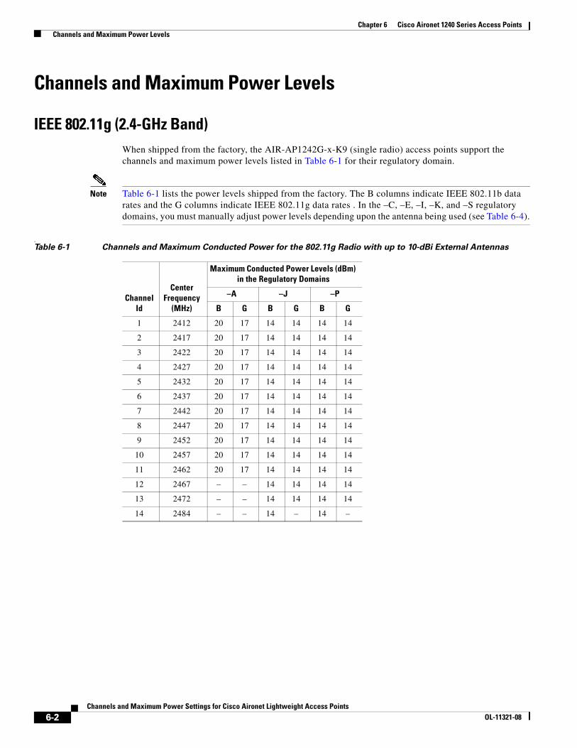
Chapter 6 Cisco Aironet 1240 Series Access Points Channels and Maximum Power Levels
Channels and Maximum Power Levels
IEEE 802.11g (2.4-GHz Band)When shipped from the factory, the AIR-AP1242G-x-K9 (single radio) access points support the channels and maximum power levels listed in Table 6-1 for their regulatory domain.
Note Table 6-1 lists the power levels shipped from the factory. The B columns indicate IEEE 802.11b data rates and the G columns indicate IEEE 802.11g data rates . In the –C, –E, –I, –K, and –S regulatory domains, you must manually adjust power levels depending upon the antenna being used (see Table 6-4).
.Table 6-1 Channels and Maximum Conducted Power for the 802.11g Radio with up to 10-dBi External Antennas
Channel Id
Center Frequency
(MHz)
Maximum Conducted Power Levels (dBm) in the Regulatory Domains
–A –J –P
B G B G B G
1 2412 20 17 14 14 14 14
2 2417 20 17 14 14 14 14
3 2422 20 17 14 14 14 14
4 2427 20 17 14 14 14 14
5 2432 20 17 14 14 14 14
6 2437 20 17 14 14 14 14
7 2442 20 17 14 14 14 14
8 2447 20 17 14 14 14 14
9 2452 20 17 14 14 14 14
10 2457 20 17 14 14 14 14
11 2462 20 17 14 14 14 14
12 2467 – – 14 14 14 14
13 2472 – – 14 14 14 14
14 2484 – – 14 – 14 –
6-2Channels and Maximum Power Settings for Cisco Aironet Lightweight Access Points
OL-11321-08
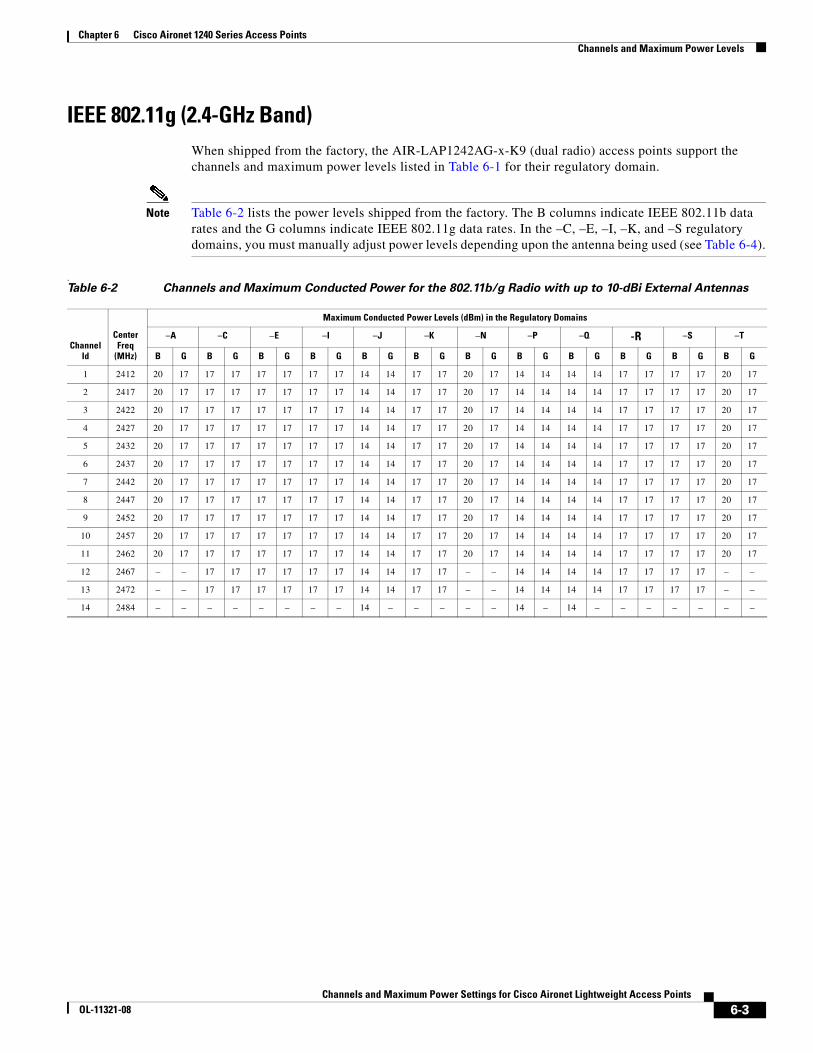
Chapter 6 Cisco Aironet 1240 Series Access Points Channels and Maximum Power Levels
IEEE 802.11g (2.4-GHz Band)When shipped from the factory, the AIR-LAP1242AG-x-K9 (dual radio) access points support the channels and maximum power levels listed in Table 6-1 for their regulatory domain.
Note Table 6-2 lists the power levels shipped from the factory. The B columns indicate IEEE 802.11b data rates and the G columns indicate IEEE 802.11g data rates. In the –C, –E, –I, –K, and –S regulatory domains, you must manually adjust power levels depending upon the antenna being used (see Table 6-4).
.Table 6-2 Channels and Maximum Conducted Power for the 802.11b/g Radio with up to 10-dBi External Antennas
Channel Id
Center Freq
(MHz)
Maximum Conducted Power Levels (dBm) in the Regulatory Domains
–A –C –E –I –J –K –N –P –Q -R –S –T
B G B G B G B G B G B G B G B G B G B G B G B G
1 2412 20 17 17 17 17 17 17 17 14 14 17 17 20 17 14 14 14 14 17 17 17 17 20 17
2 2417 20 17 17 17 17 17 17 17 14 14 17 17 20 17 14 14 14 14 17 17 17 17 20 17
3 2422 20 17 17 17 17 17 17 17 14 14 17 17 20 17 14 14 14 14 17 17 17 17 20 17
4 2427 20 17 17 17 17 17 17 17 14 14 17 17 20 17 14 14 14 14 17 17 17 17 20 17
5 2432 20 17 17 17 17 17 17 17 14 14 17 17 20 17 14 14 14 14 17 17 17 17 20 17
6 2437 20 17 17 17 17 17 17 17 14 14 17 17 20 17 14 14 14 14 17 17 17 17 20 17
7 2442 20 17 17 17 17 17 17 17 14 14 17 17 20 17 14 14 14 14 17 17 17 17 20 17
8 2447 20 17 17 17 17 17 17 17 14 14 17 17 20 17 14 14 14 14 17 17 17 17 20 17
9 2452 20 17 17 17 17 17 17 17 14 14 17 17 20 17 14 14 14 14 17 17 17 17 20 17
10 2457 20 17 17 17 17 17 17 17 14 14 17 17 20 17 14 14 14 14 17 17 17 17 20 17
11 2462 20 17 17 17 17 17 17 17 14 14 17 17 20 17 14 14 14 14 17 17 17 17 20 17
12 2467 – – 17 17 17 17 17 17 14 14 17 17 – – 14 14 14 14 17 17 17 17 – –
13 2472 – – 17 17 17 17 17 17 14 14 17 17 – – 14 14 14 14 17 17 17 17 – –
14 2484 – – – – – – – – 14 – – – – – 14 – 14 – – – – – – –
6-3Channels and Maximum Power Settings for Cisco Aironet Lightweight Access Points
OL-11321-08
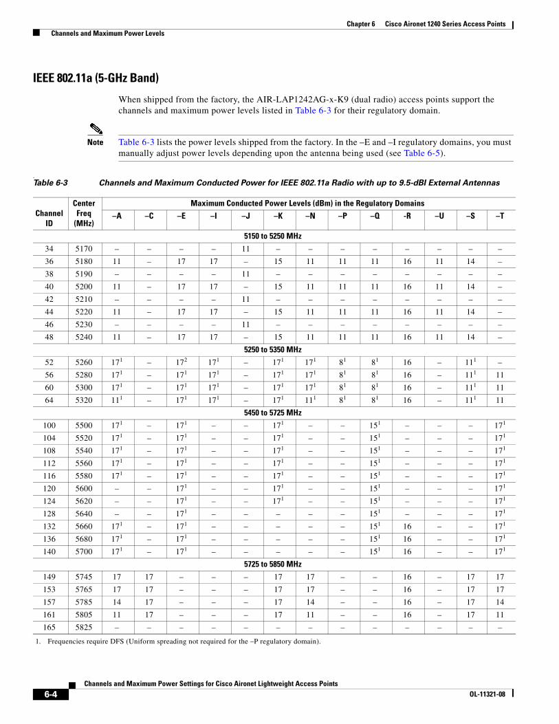
Chapter 6 Cisco Aironet 1240 Series Access Points Channels and Maximum Power Levels
IEEE 802.11a (5-GHz Band)
When shipped from the factory, the AIR-LAP1242AG-x-K9 (dual radio) access points support the channels and maximum power levels listed in Table 6-3 for their regulatory domain.
Note Table 6-3 lists the power levels shipped from the factory. In the –E and –I regulatory domains, you must manually adjust power levels depending upon the antenna being used (see Table 6-5).
.Table 6-3 Channels and Maximum Conducted Power for IEEE 802.11a Radio with up to 9.5-dBI External Antennas
Channel ID
Center Freq
(MHz)
Maximum Conducted Power Levels (dBm) in the Regulatory Domains
–A –C –E –I –J –K –N –P –Q -R –U –S –T
5150 to 5250 MHz
34 5170 – – – – 11 – – – – – – – –
36 5180 11 – 17 17 – 15 11 11 11 16 11 14 –
38 5190 – – – – 11 – – – – – – – –
40 5200 11 – 17 17 – 15 11 11 11 16 11 14 –
42 5210 – – – – 11 – – – – – – – –
44 5220 11 – 17 17 – 15 11 11 11 16 11 14 –
46 5230 – – – – 11 – – – – – – – –
48 5240 11 – 17 17 – 15 11 11 11 16 11 14 –
5250 to 5350 MHz
52 5260 171
1. Frequencies require DFS (Uniform spreading not required for the –P regulatory domain).
– 172 171 – 171 171 81 81 16 – 111 –
56 5280 171 – 171 171 – 171 171 81 81 16 – 111 11
60 5300 171 – 171 171 – 171 171 81 81 16 – 111 11
64 5320 111 – 171 171 – 171 111 81 81 16 – 111 11
5450 to 5725 MHz
100 5500 171 – 171 – – 171 – – 151 – – – 171
104 5520 171 – 171 – – 171 – – 151 – – – 171
108 5540 171 – 171 – – 171 – – 151 – – – 171
112 5560 171 – 171 – – 171 – – 151 – – – 171
116 5580 171 – 171 – – 171 – – 151 – – – 171
120 5600 – – 171 – – 171 – – 151 – – – 171
124 5620 – – 171 – – 171 – – 151 – – – 171
128 5640 – – 171 – – – – – 151 – – – 171
132 5660 171 – 171 – – – – – 151 16 – – 171
136 5680 171 – 171 – – – – – 151 16 – – 171
140 5700 171 – 171 – – – – – 151 16 – – 171
5725 to 5850 MHz
149 5745 17 17 – – – 17 17 – – 16 – 17 17
153 5765 17 17 – – – 17 17 – – 16 – 17 17
157 5785 14 17 – – – 17 14 – – 16 – 17 14
161 5805 11 17 – – – 17 11 – – 16 – 17 11
165 5825 – – – – – – – – – – – – –
6-4Channels and Maximum Power Settings for Cisco Aironet Lightweight Access Points
OL-11321-08
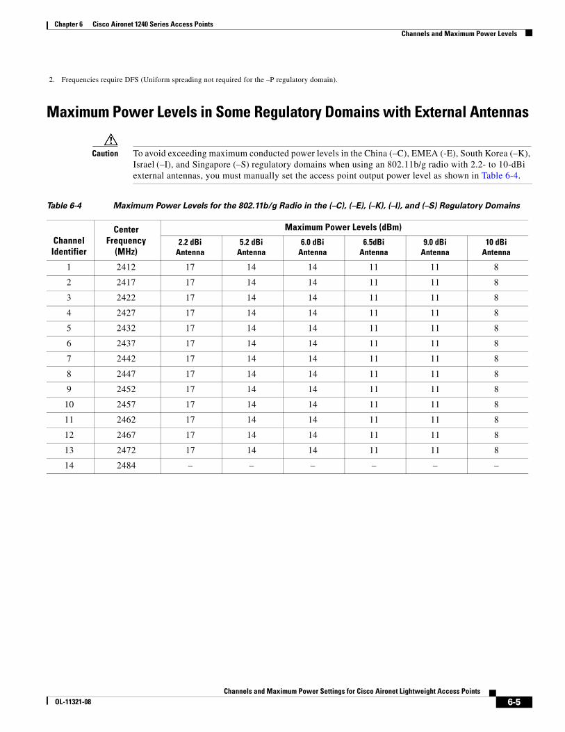
Chapter 6 Cisco Aironet 1240 Series Access Points Channels and Maximum Power Levels
Maximum Power Levels in Some Regulatory Domains with External Antennas
Caution To avoid exceeding maximum conducted power levels in the China (–C), EMEA (-E), South Korea (–K), Israel (–I), and Singapore (–S) regulatory domains when using an 802.11b/g radio with 2.2- to 10-dBi external antennas, you must manually set the access point output power level as shown in Table 6-4.
2. Frequencies require DFS (Uniform spreading not required for the –P regulatory domain).
Table 6-4 Maximum Power Levels for the 802.11b/g Radio in the (–C), (–E), (–K), (–I), and (–S) Regulatory Domains
Channel Identifier
Center Frequency
(MHz)
Maximum Power Levels (dBm)
2.2 dBiAntenna
5.2 dBi Antenna
6.0 dBi Antenna
6.5dBi Antenna
9.0 dBi Antenna
10 dBi Antenna
1 2412 17 14 14 11 11 8
2 2417 17 14 14 11 11 8
3 2422 17 14 14 11 11 8
4 2427 17 14 14 11 11 8
5 2432 17 14 14 11 11 8
6 2437 17 14 14 11 11 8
7 2442 17 14 14 11 11 8
8 2447 17 14 14 11 11 8
9 2452 17 14 14 11 11 8
10 2457 17 14 14 11 11 8
11 2462 17 14 14 11 11 8
12 2467 17 14 14 11 11 8
13 2472 17 14 14 11 11 8
14 2484 – – – – – –
6-5Channels and Maximum Power Settings for Cisco Aironet Lightweight Access Points
OL-11321-08
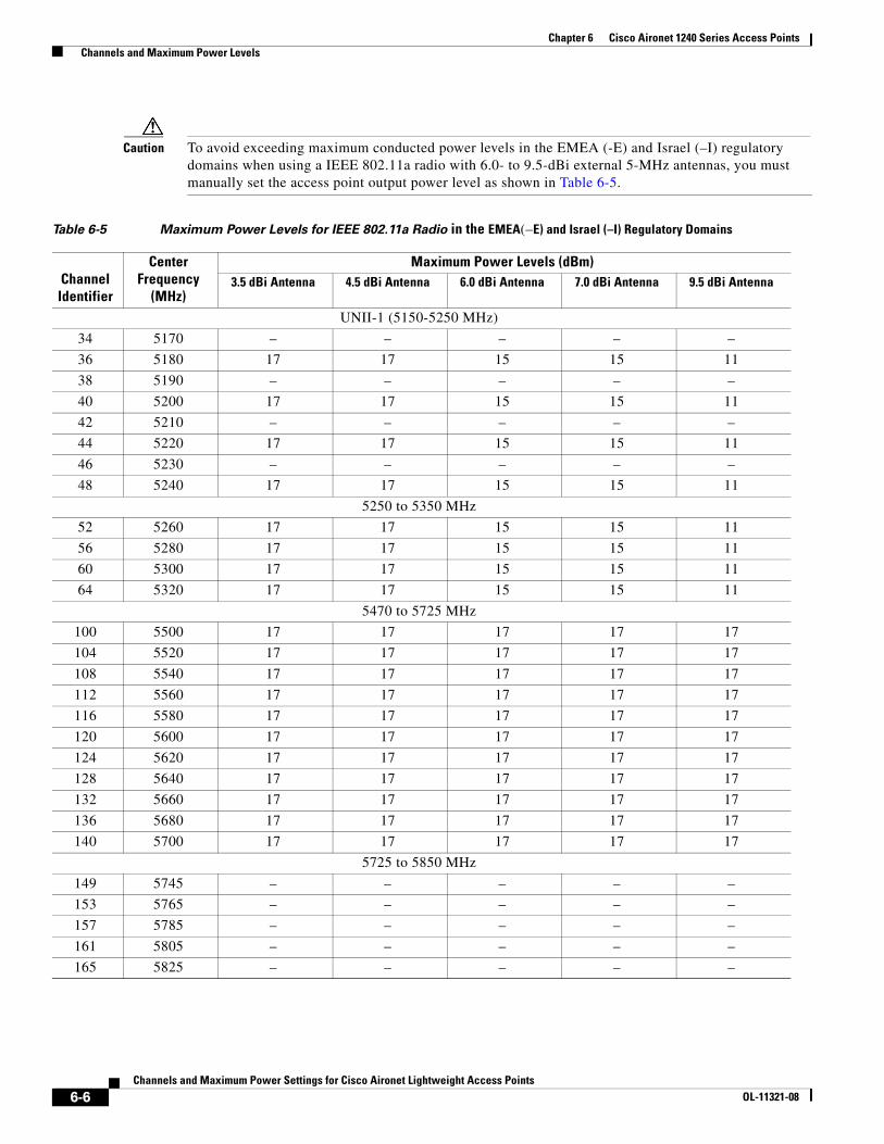
Chapter 6 Cisco Aironet 1240 Series Access Points Channels and Maximum Power Levels
Caution To avoid exceeding maximum conducted power levels in the EMEA (-E) and Israel (–I) regulatory domains when using a IEEE 802.11a radio with 6.0- to 9.5-dBi external 5-MHz antennas, you must manually set the access point output power level as shown in Table 6-5.
Table 6-5 Maximum Power Levels for IEEE 802.11a Radio in the EMEA(–E) and Israel (–I) Regulatory Domains
Channel Identifier
Center Frequency
(MHz)
Maximum Power Levels (dBm) 3.5 dBi Antenna 4.5 dBi Antenna 6.0 dBi Antenna 7.0 dBi Antenna 9.5 dBi Antenna
UNII-1 (5150-5250 MHz)
34 5170 – – – – –
36 5180 17 17 15 15 11
38 5190 – – – – –
40 5200 17 17 15 15 11
42 5210 – – – – –
44 5220 17 17 15 15 11
46 5230 – – – – –
48 5240 17 17 15 15 11
5250 to 5350 MHz
52 5260 17 17 15 15 11
56 5280 17 17 15 15 11
60 5300 17 17 15 15 11
64 5320 17 17 15 15 11
5470 to 5725 MHz
100 5500 17 17 17 17 17
104 5520 17 17 17 17 17
108 5540 17 17 17 17 17
112 5560 17 17 17 17 17
116 5580 17 17 17 17 17
120 5600 17 17 17 17 17
124 5620 17 17 17 17 17
128 5640 17 17 17 17 17
132 5660 17 17 17 17 17
136 5680 17 17 17 17 17
140 5700 17 17 17 17 17
5725 to 5850 MHz
149 5745 – – – – –
153 5765 – – – – –
157 5785 – – – – –
161 5805 – – – – –
165 5825 – – – – –
6-6Channels and Maximum Power Settings for Cisco Aironet Lightweight Access Points
OL-11321-08

Chapter 6 Cisco Aironet 1240 Series Access Points Special Country Restrictions
Special Country RestrictionsTable 6-7 lists special restrictions for wireless operation in some countries.
Table 6-6 Maximum Power Levels for IEEE 802.11a Radio in the Russia (-R) Regulatory Domain
Channel Identifier
Center Frequency
(MHz)
Maximum Power Levels (dBm) 3.5 dBi Antenna 4.5 dBi Antenna 6.0 dBi Antenna 7.0 dBi Antenna 9.5 dBi Antenna
UNII-1 (5150-5250 MHz)
34 5170 – – – – –
36 5180 16 15 14 13 10
38 5190 – – – – –
40 5200 16 15 14 13 10
42 5210 – – – – –
44 5220 16 15 14 13 10
46 5230 – – – – –
48 5240 16 15 14 13 10
5250 to 5350 MHz
52 5260 16 15 14 13 10
56 5280 16 15 14 13 10
60 5300 16 15 14 13 10
64 5320 16 15 14 13 10
5470 to 5725 MHz
100 5500 – – – – –
104 5520 – – – – –
108 5540 – – – – –
112 5560 – – – – –
116 5580 – – – – –
120 5600 – – – – –
124 5620 – – – – –
128 5640 – – – – –
132 5660 16 15 14 13 10
136 5680 16 15 14 13 10
140 5700 16 15 14 13 10
5725 to 5850 MHz
149 5745 16 15 14 13 10
153 5765 16 15 14 13 10
157 5785 16 15 14 13 10
161 5805 16 15 14 13 10
165 5825 – – – – –
6-7Channels and Maximum Power Settings for Cisco Aironet Lightweight Access Points
OL-11321-08
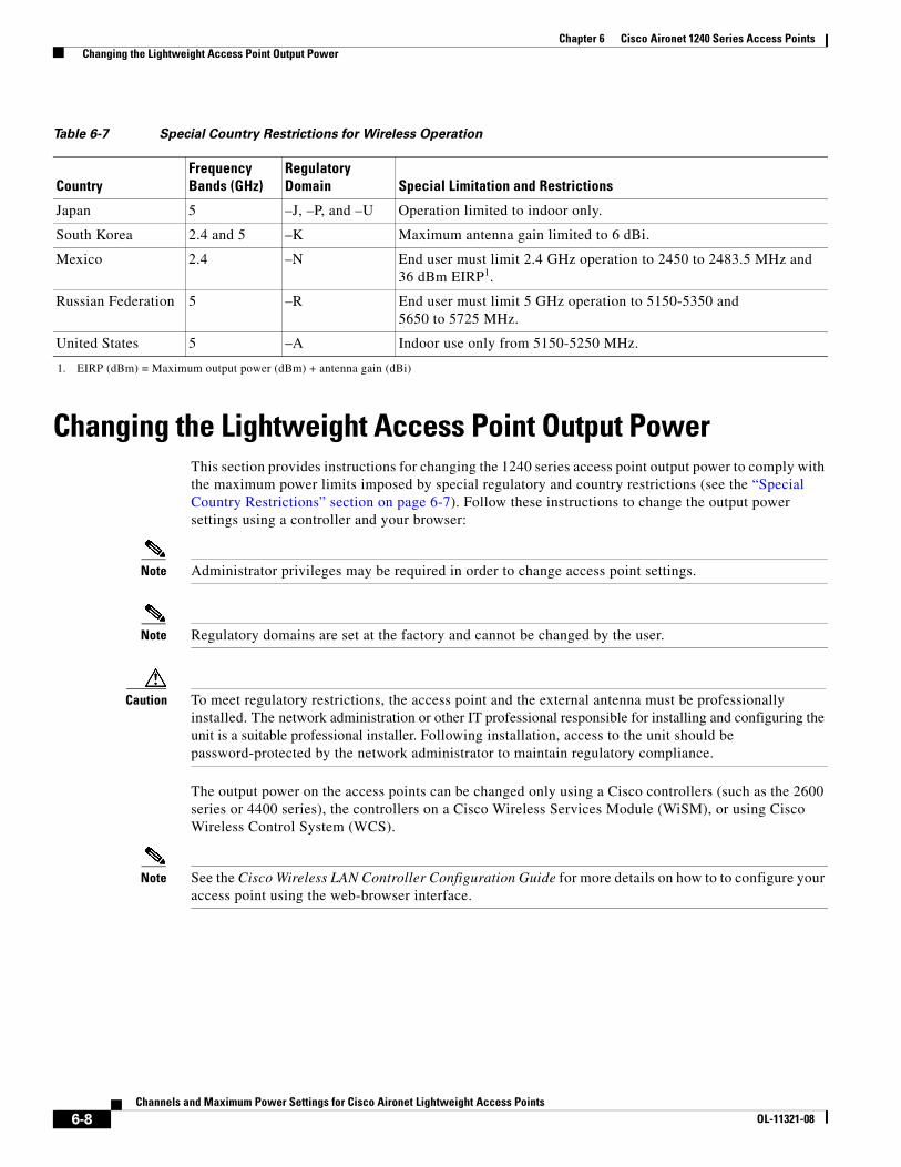
Chapter 6 Cisco Aironet 1240 Series Access Points Changing the Lightweight Access Point Output Power
Changing the Lightweight Access Point Output PowerThis section provides instructions for changing the 1240 series access point output power to comply with the maximum power limits imposed by special regulatory and country restrictions (see the “Special Country Restrictions” section on page 6-7). Follow these instructions to change the output power settings using a controller and your browser:
Note Administrator privileges may be required in order to change access point settings.
Note Regulatory domains are set at the factory and cannot be changed by the user.
Caution To meet regulatory restrictions, the access point and the external antenna must be professionally installed. The network administration or other IT professional responsible for installing and configuring the unit is a suitable professional installer. Following installation, access to the unit should be password-protected by the network administrator to maintain regulatory compliance.
The output power on the access points can be changed only using a Cisco controllers (such as the 2600 series or 4400 series), the controllers on a Cisco Wireless Services Module (WiSM), or using Cisco Wireless Control System (WCS).
Note See the Cisco Wireless LAN Controller Configuration Guide for more details on how to to configure your access point using the web-browser interface.
Table 6-7 Special Country Restrictions for Wireless Operation
CountryFrequency Bands (GHz)
Regulatory Domain Special Limitation and Restrictions
Japan 5 –J, –P, and –U Operation limited to indoor only.
South Korea 2.4 and 5 –K Maximum antenna gain limited to 6 dBi.
Mexico 2.4 –N End user must limit 2.4 GHz operation to 2450 to 2483.5 MHz and 36 dBm EIRP1.
1. EIRP (dBm) = Maximum output power (dBm) + antenna gain (dBi)
Russian Federation 5 –R End user must limit 5 GHz operation to 5150-5350 and 5650 to 5725 MHz.
United States 5 –A Indoor use only from 5150-5250 MHz.
6-8Channels and Maximum Power Settings for Cisco Aironet Lightweight Access Points
OL-11321-08
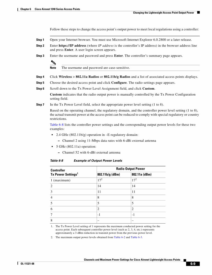
Chapter 6 Cisco Aironet 1240 Series Access Points Changing the Lightweight Access Point Output Power
Follow these steps to change the access point’s output power to meet local regulations using a controller:
Step 1 Open your Internet browser. You must use Microsoft Internet Explorer 6.0.2800 or a later release.
Step 2 Enter https://IP address (where IP address is the controller’s IP address) in the browser address line and press Enter. A user login screen appears.
Step 3 Enter the username and password and press Enter. The controller’s summary page appears.
Note The username and password are case-sensitive.
Step 4 Click Wireless > 802.11a Radios or 802.11b/g Radios and a list of associated access points displays.
Step 5 Choose the desired access point and click Configure. The radio settings page appears.
Step 6 Scroll down to the Tx Power Level Assignment field, and click Custom.
Custom indicates that the radio output power is manually controlled by the Tx Power Configuration setting field.
Step 7 In the Tx Power Level field, select the appropriate power level setting (1 to 8).
Based on the operating channel, the regulatory domain, and the controller power level setting (1 to 8), the actual transmit power at the access point can be reduced to comply with special regulatory or country restrictions.
Table 6-8 lists the controller power settings and the corresponding output power levels for these two examples:
• 2.4 GHz (802.11b/g) operation in –E regulatory domain:
– Channel 2 using 11-Mbps data rates with 6-dBi external antenna
• 5 GHz (802.11a) operation:
– Channel 52 with 6-dBi external antenna
Table 6-8 Example of Output Power Levels
Controller Tx Power Settings1
1. The Tx Power Level setting of 1 represents the maximum conducted power setting for the access point. Each subsequent controller power level (such as 2, 3, 4, etc.) represents approximately a 3-dBm reduction in transmit power from the previous power level.
Radio Output Power
802.11b/g (dBm) 802.11a (dBm)
1 (maximum) 172
2. The maximum output power levels obtained from Table 6-2 and Table 6-3.
172
2 14 14
3 11 11
4 8 8
5 5 5
6 2 2
7 -1 -1
8 – –
6-9Channels and Maximum Power Settings for Cisco Aironet Lightweight Access Points
OL-11321-08
Chapter 6 Cisco Aironet 1240 Series Access Points Changing the Lightweight Access Point Output Power
• For 802.11b/g (see Table 6-4 and Table 6-8), the manual controller Tx Power Level setting is 2.
• For 802.11a (see Table 6-5 and Table 6-8), the manual controller Tx Power Level setting is 2.
Step 8 Click Apply.
Step 9 Close your Internet browser.
6-10Channels and Maximum Power Settings for Cisco Aironet Lightweight Access Points
OL-11321-08
Channels and Maximum Power SeOL-11321-08
C H A P T E R 7
Cisco Aironet 1250 Series Lightweight Access PointsThis section lists the 1250 series lightweight access points (model: AIR-LAP1251) 2.4-GHz and 5-GHz ( draft IEEE 802.11n version 2.0) radio channels and maximum power levels supported by the world’s regulatory domains. The following topics are covered in this section:
• Channels and Maximum Power Levels, page 7-2
• Special Country Restrictions, page 7-21
• Changing Lightweight Access Point Output Power, page 7-21
7-1ttings for Cisco Aironet Lightweight Access Points
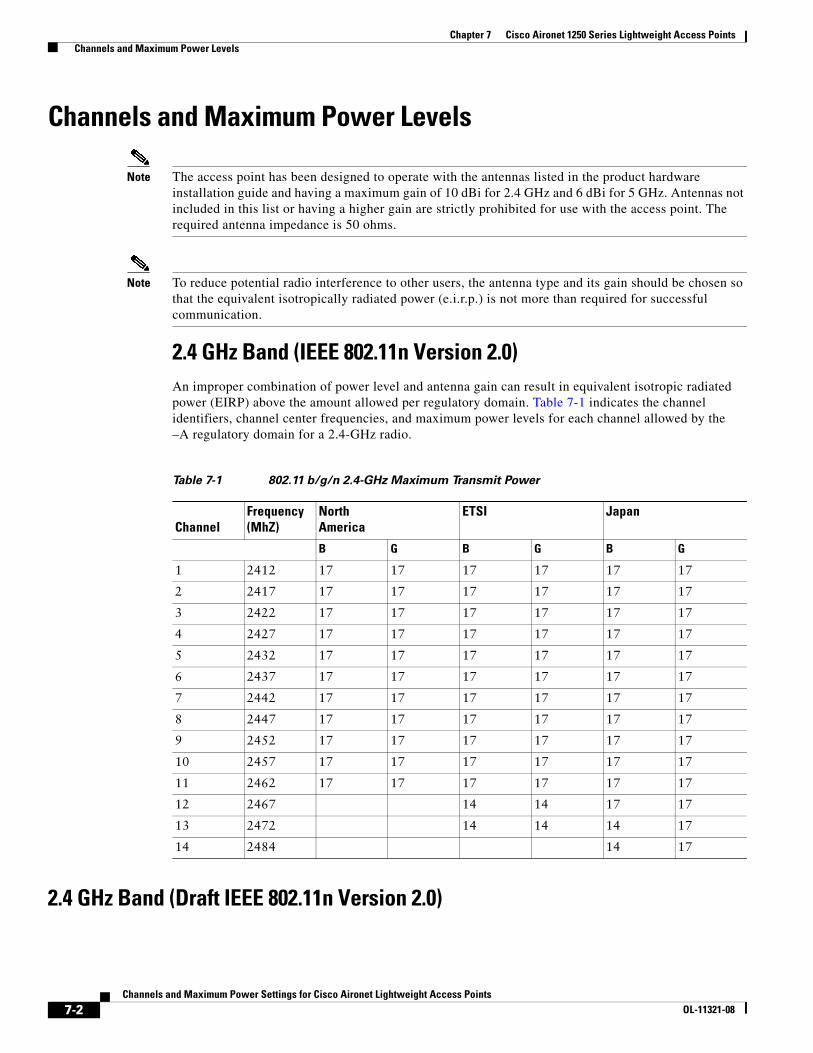
Chapter 7 Cisco Aironet 1250 Series Lightweight Access Points Channels and Maximum Power Levels
Channels and Maximum Power Levels
Note The access point has been designed to operate with the antennas listed in the product hardware installation guide and having a maximum gain of 10 dBi for 2.4 GHz and 6 dBi for 5 GHz. Antennas not included in this list or having a higher gain are strictly prohibited for use with the access point. The required antenna impedance is 50 ohms.
Note To reduce potential radio interference to other users, the antenna type and its gain should be chosen so that the equivalent isotropically radiated power (e.i.r.p.) is not more than required for successful communication.
2.4 GHz Band (IEEE 802.11n Version 2.0) An improper combination of power level and antenna gain can result in equivalent isotropic radiated power (EIRP) above the amount allowed per regulatory domain. Table 7-1 indicates the channel identifiers, channel center frequencies, and maximum power levels for each channel allowed by the–A regulatory domain for a 2.4-GHz radio.
2.4 GHz Band (Draft IEEE 802.11n Version 2.0)
Table 7-1 802.11 b/g/n 2.4-GHz Maximum Transmit Power
ChannelFrequency (MhZ)
North America
ETSI Japan
B G B G B G
1 2412 17 17 17 17 17 17
2 2417 17 17 17 17 17 17
3 2422 17 17 17 17 17 17
4 2427 17 17 17 17 17 17
5 2432 17 17 17 17 17 17
6 2437 17 17 17 17 17 17
7 2442 17 17 17 17 17 17
8 2447 17 17 17 17 17 17
9 2452 17 17 17 17 17 17
10 2457 17 17 17 17 17 17
11 2462 17 17 17 17 17 17
12 2467 14 14 17 17
13 2472 14 14 14 17
14 2484 14 17
7-2Channels and Maximum Power Settings for Cisco Aironet Lightweight Access Points
OL-11321-08
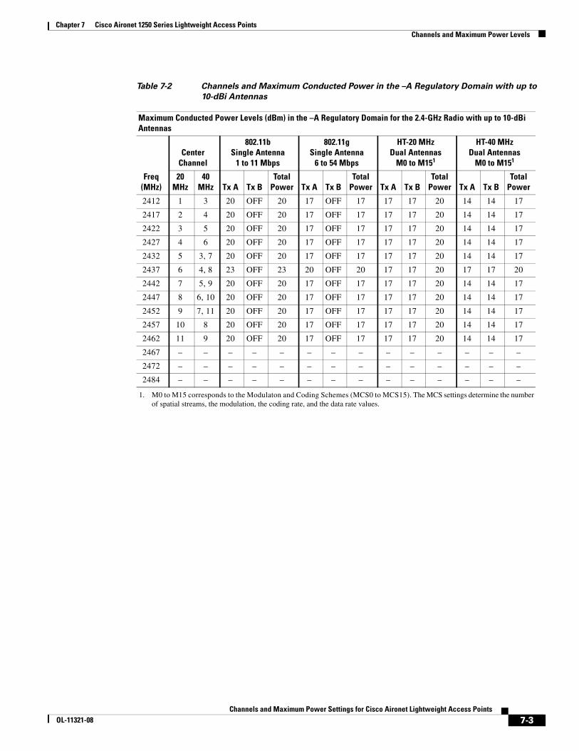
Chapter 7 Cisco Aironet 1250 Series Lightweight Access Points Channels and Maximum Power Levels
Table 7-2 Channels and Maximum Conducted Power in the –A Regulatory Domain with up to
10-dBi Antennas
Maximum Conducted Power Levels (dBm) in the –A Regulatory Domain for the 2.4-GHz Radio with up to 10-dBi Antennas
Freq(MHz)
CenterChannel
802.11bSingle Antenna
1 to 11 Mbps
802.11gSingle Antenna
6 to 54 Mbps
HT-20 MHzDual Antennas
M0 to M151
1. M0 to M15 corresponds to the Modulaton and Coding Schemes (MCS0 to MCS15). The MCS settings determine the number of spatial streams, the modulation, the coding rate, and the data rate values.
HT-40 MHzDual Antennas
M0 to M151
20MHz
40MHz Tx A Tx B
TotalPower Tx A Tx B
TotalPower Tx A Tx B
TotalPower Tx A Tx B
TotalPower
2412 1 3 20 OFF 20 17 OFF 17 17 17 20 14 14 17
2417 2 4 20 OFF 20 17 OFF 17 17 17 20 14 14 17
2422 3 5 20 OFF 20 17 OFF 17 17 17 20 14 14 17
2427 4 6 20 OFF 20 17 OFF 17 17 17 20 14 14 17
2432 5 3, 7 20 OFF 20 17 OFF 17 17 17 20 14 14 17
2437 6 4, 8 23 OFF 23 20 OFF 20 17 17 20 17 17 20
2442 7 5, 9 20 OFF 20 17 OFF 17 17 17 20 14 14 17
2447 8 6, 10 20 OFF 20 17 OFF 17 17 17 20 14 14 17
2452 9 7, 11 20 OFF 20 17 OFF 17 17 17 20 14 14 17
2457 10 8 20 OFF 20 17 OFF 17 17 17 20 14 14 17
2462 11 9 20 OFF 20 17 OFF 17 17 17 20 14 14 17
2467 – – – – – – – – – – – – – –
2472 – – – – – – – – – – – – – –
2484 – – – – – – – – – – – – – –
7-3Channels and Maximum Power Settings for Cisco Aironet Lightweight Access Points
OL-11321-08
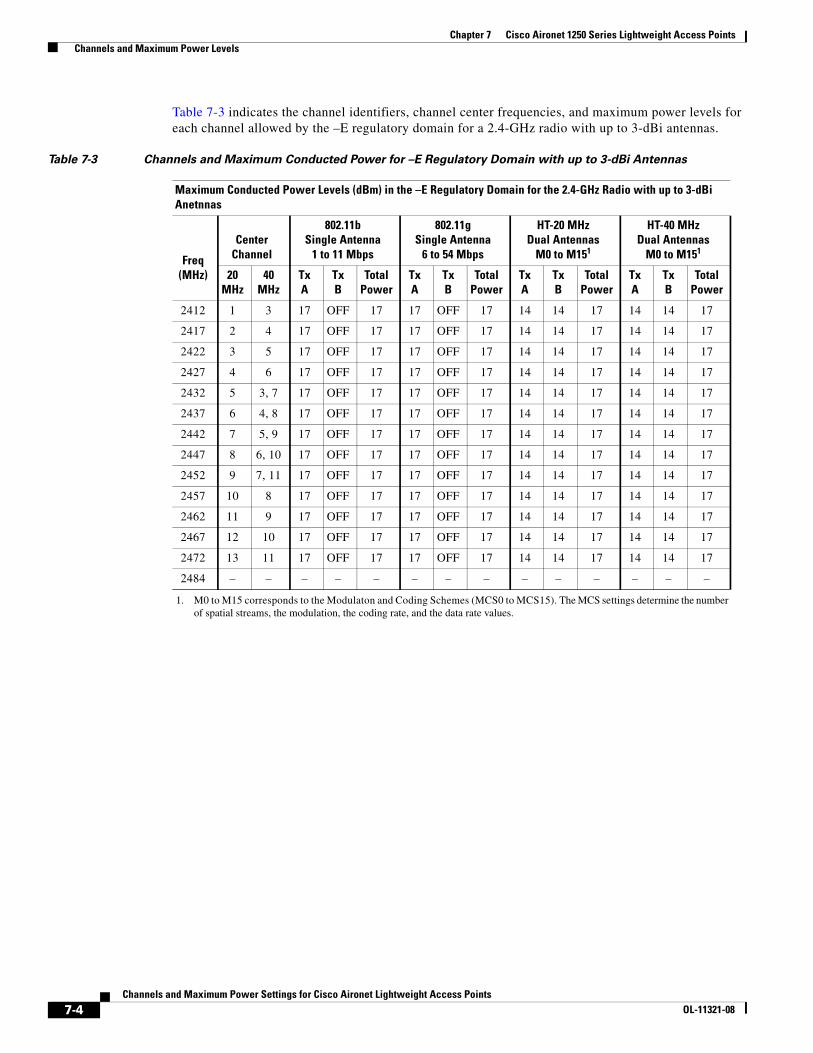
Chapter 7 Cisco Aironet 1250 Series Lightweight Access Points Channels and Maximum Power Levels
Table 7-3 indicates the channel identifiers, channel center frequencies, and maximum power levels for each channel allowed by the –E regulatory domain for a 2.4-GHz radio with up to 3-dBi antennas.
Table 7-3 Channels and Maximum Conducted Power for –E Regulatory Domain with up to 3-dBi Antennas
Maximum Conducted Power Levels (dBm) in the –E Regulatory Domain for the 2.4-GHz Radio with up to 3-dBi Anetnnas
Freq(MHz)
CenterChannel
802.11bSingle Antenna
1 to 11 Mbps
802.11gSingle Antenna
6 to 54 Mbps
HT-20 MHzDual Antennas
M0 to M151
1. M0 to M15 corresponds to the Modulaton and Coding Schemes (MCS0 to MCS15). The MCS settings determine the number of spatial streams, the modulation, the coding rate, and the data rate values.
HT-40 MHzDual Antennas
M0 to M151
20MHz
40MHz
TxA
TxB
TotalPower
TxA
TxB
TotalPower
TxA
TxB
TotalPower
TxA
TxB
TotalPower
2412 1 3 17 OFF 17 17 OFF 17 14 14 17 14 14 17
2417 2 4 17 OFF 17 17 OFF 17 14 14 17 14 14 17
2422 3 5 17 OFF 17 17 OFF 17 14 14 17 14 14 17
2427 4 6 17 OFF 17 17 OFF 17 14 14 17 14 14 17
2432 5 3, 7 17 OFF 17 17 OFF 17 14 14 17 14 14 17
2437 6 4, 8 17 OFF 17 17 OFF 17 14 14 17 14 14 17
2442 7 5, 9 17 OFF 17 17 OFF 17 14 14 17 14 14 17
2447 8 6, 10 17 OFF 17 17 OFF 17 14 14 17 14 14 17
2452 9 7, 11 17 OFF 17 17 OFF 17 14 14 17 14 14 17
2457 10 8 17 OFF 17 17 OFF 17 14 14 17 14 14 17
2462 11 9 17 OFF 17 17 OFF 17 14 14 17 14 14 17
2467 12 10 17 OFF 17 17 OFF 17 14 14 17 14 14 17
2472 13 11 17 OFF 17 17 OFF 17 14 14 17 14 14 17
2484 – – – – – – – – – – – – – –
7-4Channels and Maximum Power Settings for Cisco Aironet Lightweight Access Points
OL-11321-08
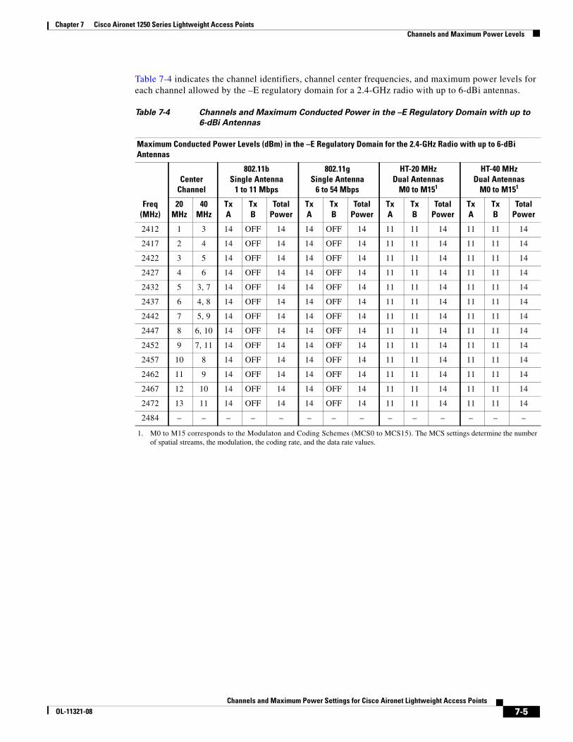
Chapter 7 Cisco Aironet 1250 Series Lightweight Access Points Channels and Maximum Power Levels
Table 7-4 indicates the channel identifiers, channel center frequencies, and maximum power levels for each channel allowed by the –E regulatory domain for a 2.4-GHz radio with up to 6-dBi antennas.
Table 7-4 Channels and Maximum Conducted Power in the –E Regulatory Domain with up to
6-dBi Antennas
Maximum Conducted Power Levels (dBm) in the –E Regulatory Domain for the 2.4-GHz Radio with up to 6-dBi Antennas
Freq(MHz)
CenterChannel
802.11bSingle Antenna
1 to 11 Mbps
802.11gSingle Antenna
6 to 54 Mbps
HT-20 MHzDual Antennas
M0 to M151
1. M0 to M15 corresponds to the Modulaton and Coding Schemes (MCS0 to MCS15). The MCS settings determine the number of spatial streams, the modulation, the coding rate, and the data rate values.
HT-40 MHzDual Antennas
M0 to M151
20MHz
40MHz
TxA
TxB
TotalPower
TxA
TxB
TotalPower
TxA
TxB
TotalPower
TxA
TxB
TotalPower
2412 1 3 14 OFF 14 14 OFF 14 11 11 14 11 11 14
2417 2 4 14 OFF 14 14 OFF 14 11 11 14 11 11 14
2422 3 5 14 OFF 14 14 OFF 14 11 11 14 11 11 14
2427 4 6 14 OFF 14 14 OFF 14 11 11 14 11 11 14
2432 5 3, 7 14 OFF 14 14 OFF 14 11 11 14 11 11 14
2437 6 4, 8 14 OFF 14 14 OFF 14 11 11 14 11 11 14
2442 7 5, 9 14 OFF 14 14 OFF 14 11 11 14 11 11 14
2447 8 6, 10 14 OFF 14 14 OFF 14 11 11 14 11 11 14
2452 9 7, 11 14 OFF 14 14 OFF 14 11 11 14 11 11 14
2457 10 8 14 OFF 14 14 OFF 14 11 11 14 11 11 14
2462 11 9 14 OFF 14 14 OFF 14 11 11 14 11 11 14
2467 12 10 14 OFF 14 14 OFF 14 11 11 14 11 11 14
2472 13 11 14 OFF 14 14 OFF 14 11 11 14 11 11 14
2484 – – – – – – – – – – – – – –
7-5Channels and Maximum Power Settings for Cisco Aironet Lightweight Access Points
OL-11321-08
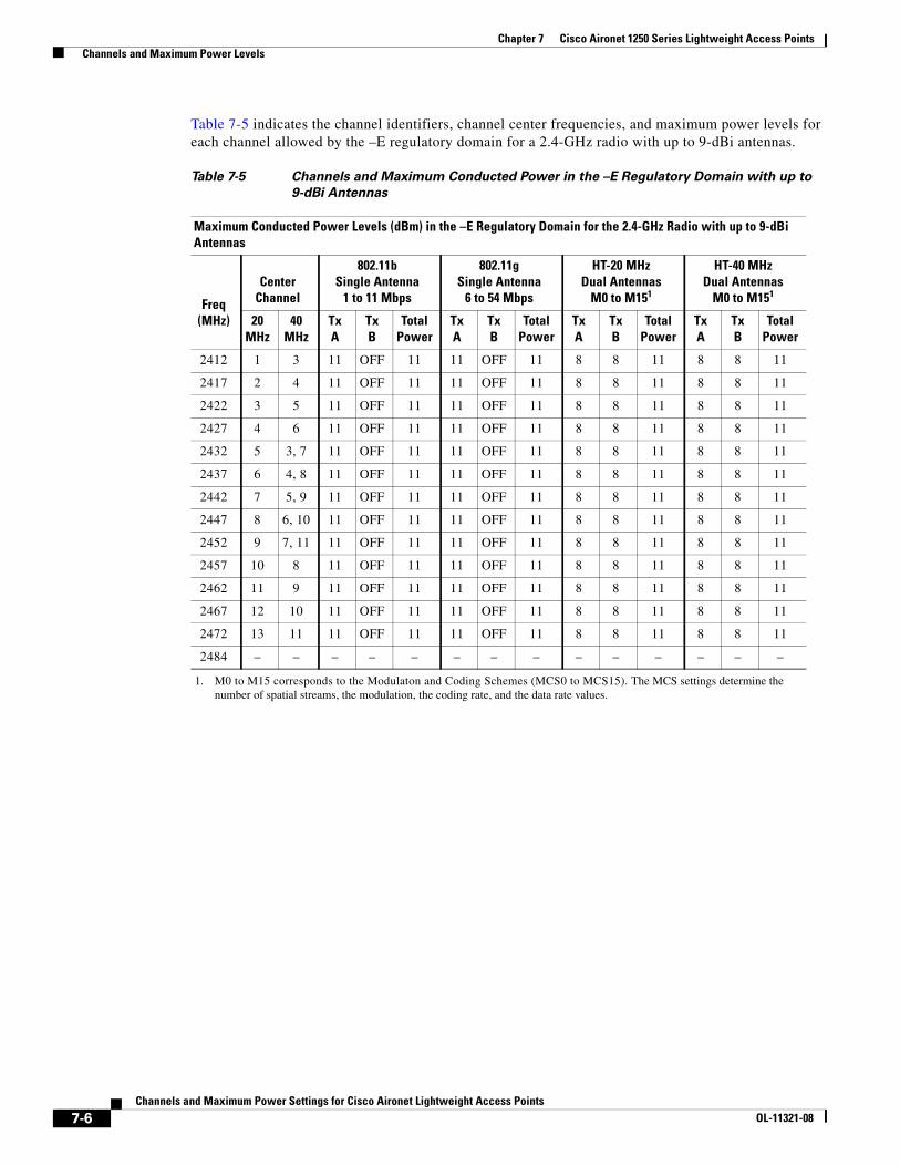
Chapter 7 Cisco Aironet 1250 Series Lightweight Access Points Channels and Maximum Power Levels
Table 7-5 indicates the channel identifiers, channel center frequencies, and maximum power levels for each channel allowed by the –E regulatory domain for a 2.4-GHz radio with up to 9-dBi antennas.
Table 7-5 Channels and Maximum Conducted Power in the –E Regulatory Domain with up to
9-dBi Antennas
Maximum Conducted Power Levels (dBm) in the –E Regulatory Domain for the 2.4-GHz Radio with up to 9-dBi Antennas
Freq(MHz)
CenterChannel
802.11bSingle Antenna
1 to 11 Mbps
802.11gSingle Antenna
6 to 54 Mbps
HT-20 MHzDual Antennas
M0 to M151
1. M0 to M15 corresponds to the Modulaton and Coding Schemes (MCS0 to MCS15). The MCS settings determine the number of spatial streams, the modulation, the coding rate, and the data rate values.
HT-40 MHzDual Antennas
M0 to M151
20MHz
40MHz
TxA
TxB
TotalPower
TxA
TxB
TotalPower
TxA
TxB
TotalPower
TxA
TxB
TotalPower
2412 1 3 11 OFF 11 11 OFF 11 8 8 11 8 8 11
2417 2 4 11 OFF 11 11 OFF 11 8 8 11 8 8 11
2422 3 5 11 OFF 11 11 OFF 11 8 8 11 8 8 11
2427 4 6 11 OFF 11 11 OFF 11 8 8 11 8 8 11
2432 5 3, 7 11 OFF 11 11 OFF 11 8 8 11 8 8 11
2437 6 4, 8 11 OFF 11 11 OFF 11 8 8 11 8 8 11
2442 7 5, 9 11 OFF 11 11 OFF 11 8 8 11 8 8 11
2447 8 6, 10 11 OFF 11 11 OFF 11 8 8 11 8 8 11
2452 9 7, 11 11 OFF 11 11 OFF 11 8 8 11 8 8 11
2457 10 8 11 OFF 11 11 OFF 11 8 8 11 8 8 11
2462 11 9 11 OFF 11 11 OFF 11 8 8 11 8 8 11
2467 12 10 11 OFF 11 11 OFF 11 8 8 11 8 8 11
2472 13 11 11 OFF 11 11 OFF 11 8 8 11 8 8 11
2484 – – – – – – – – – – – – – –
7-6Channels and Maximum Power Settings for Cisco Aironet Lightweight Access Points
OL-11321-08
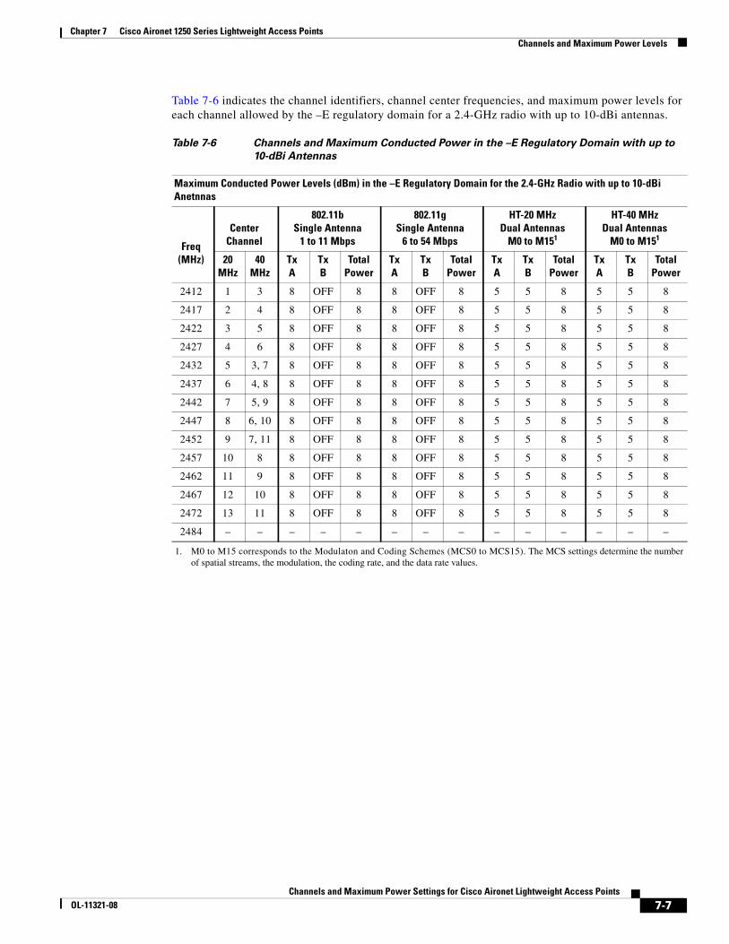
Chapter 7 Cisco Aironet 1250 Series Lightweight Access Points Channels and Maximum Power Levels
Table 7-6 indicates the channel identifiers, channel center frequencies, and maximum power levels for each channel allowed by the –E regulatory domain for a 2.4-GHz radio with up to 10-dBi antennas.
Table 7-6 Channels and Maximum Conducted Power in the –E Regulatory Domain with up to
10-dBi Antennas
Maximum Conducted Power Levels (dBm) in the –E Regulatory Domain for the 2.4-GHz Radio with up to 10-dBi Anetnnas
Freq(MHz)
CenterChannel
802.11bSingle Antenna
1 to 11 Mbps
802.11gSingle Antenna
6 to 54 Mbps
HT-20 MHzDual Antennas
M0 to M151
1. M0 to M15 corresponds to the Modulaton and Coding Schemes (MCS0 to MCS15). The MCS settings determine the number of spatial streams, the modulation, the coding rate, and the data rate values.
HT-40 MHzDual Antennas
M0 to M151
20MHz
40MHz
TxA
TxB
TotalPower
TxA
TxB
TotalPower
TxA
TxB
TotalPower
TxA
TxB
TotalPower
2412 1 3 8 OFF 8 8 OFF 8 5 5 8 5 5 8
2417 2 4 8 OFF 8 8 OFF 8 5 5 8 5 5 8
2422 3 5 8 OFF 8 8 OFF 8 5 5 8 5 5 8
2427 4 6 8 OFF 8 8 OFF 8 5 5 8 5 5 8
2432 5 3, 7 8 OFF 8 8 OFF 8 5 5 8 5 5 8
2437 6 4, 8 8 OFF 8 8 OFF 8 5 5 8 5 5 8
2442 7 5, 9 8 OFF 8 8 OFF 8 5 5 8 5 5 8
2447 8 6, 10 8 OFF 8 8 OFF 8 5 5 8 5 5 8
2452 9 7, 11 8 OFF 8 8 OFF 8 5 5 8 5 5 8
2457 10 8 8 OFF 8 8 OFF 8 5 5 8 5 5 8
2462 11 9 8 OFF 8 8 OFF 8 5 5 8 5 5 8
2467 12 10 8 OFF 8 8 OFF 8 5 5 8 5 5 8
2472 13 11 8 OFF 8 8 OFF 8 5 5 8 5 5 8
2484 – – – – – – – – – – – – – –
7-7Channels and Maximum Power Settings for Cisco Aironet Lightweight Access Points
OL-11321-08
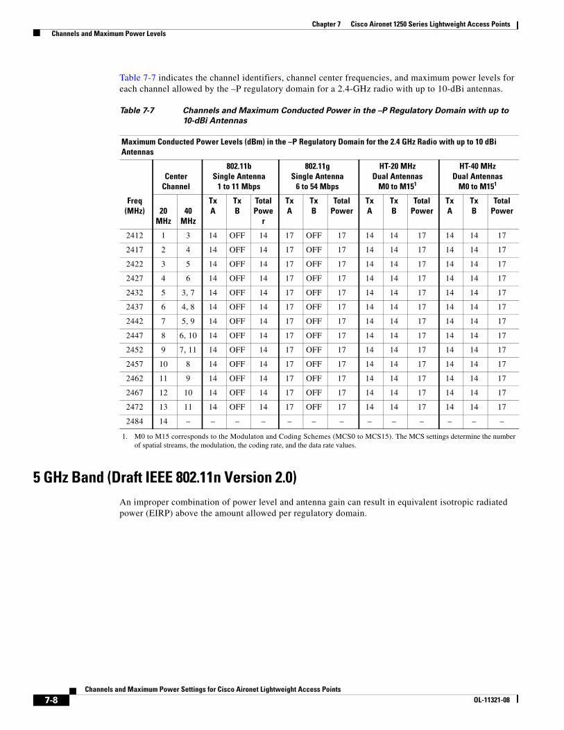
Chapter 7 Cisco Aironet 1250 Series Lightweight Access Points Channels and Maximum Power Levels
Table 7-7 indicates the channel identifiers, channel center frequencies, and maximum power levels for each channel allowed by the –P regulatory domain for a 2.4-GHz radio with up to 10-dBi antennas.
5 GHz Band (Draft IEEE 802.11n Version 2.0)An improper combination of power level and antenna gain can result in equivalent isotropic radiated power (EIRP) above the amount allowed per regulatory domain.
Table 7-7 Channels and Maximum Conducted Power in the –P Regulatory Domain with up to
10-dBi Antennas
Maximum Conducted Power Levels (dBm) in the –P Regulatory Domain for the 2.4 GHz Radio with up to 10 dBi Antennas
Freq(MHz)
CenterChannel
802.11bSingle Antenna
1 to 11 Mbps
802.11gSingle Antenna
6 to 54 Mbps
HT-20 MHzDual Antennas
M0 to M151
1. M0 to M15 corresponds to the Modulaton and Coding Schemes (MCS0 to MCS15). The MCS settings determine the number of spatial streams, the modulation, the coding rate, and the data rate values.
HT-40 MHzDual Antennas
M0 to M151
20MHz
40MHz
TxA
TxB
TotalPowe
r
TxA
TxB
TotalPower
TxA
TxB
TotalPower
TxA
TxB
TotalPower
2412 1 3 14 OFF 14 17 OFF 17 14 14 17 14 14 17
2417 2 4 14 OFF 14 17 OFF 17 14 14 17 14 14 17
2422 3 5 14 OFF 14 17 OFF 17 14 14 17 14 14 17
2427 4 6 14 OFF 14 17 OFF 17 14 14 17 14 14 17
2432 5 3, 7 14 OFF 14 17 OFF 17 14 14 17 14 14 17
2437 6 4, 8 14 OFF 14 17 OFF 17 14 14 17 14 14 17
2442 7 5, 9 14 OFF 14 17 OFF 17 14 14 17 14 14 17
2447 8 6, 10 14 OFF 14 17 OFF 17 14 14 17 14 14 17
2452 9 7, 11 14 OFF 14 17 OFF 17 14 14 17 14 14 17
2457 10 8 14 OFF 14 17 OFF 17 14 14 17 14 14 17
2462 11 9 14 OFF 14 17 OFF 17 14 14 17 14 14 17
2467 12 10 14 OFF 14 17 OFF 17 14 14 17 14 14 17
2472 13 11 14 OFF 14 17 OFF 17 14 14 17 14 14 17
2484 14 – – – – – – – – – – – – –
7-8Channels and Maximum Power Settings for Cisco Aironet Lightweight Access Points
OL-11321-08
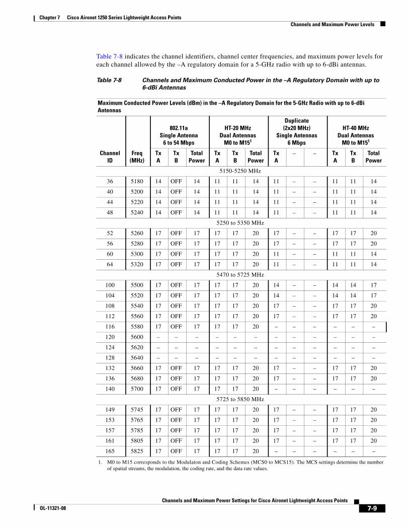
Chapter 7 Cisco Aironet 1250 Series Lightweight Access Points Channels and Maximum Power Levels
Table 7-8 indicates the channel identifiers, channel center frequencies, and maximum power levels for each channel allowed by the –A regulatory domain for a 5-GHz radio with up to 6-dBi antennas.
Table 7-8 Channels and Maximum Conducted Power in the –A Regulatory Domain with up to
6-dBi Antennas
Maximum Conducted Power Levels (dBm) in the –A Regulatory Domain for the 5-GHz Radio with up to 6-dBi Antennas
ChannelID
Freq(MHz)
802.11aSingle Antenna
6 to 54 Mbps
HT-20 MHzDual Antennas
M0 to M151
1. M0 to M15 corresponds to the Modulaton and Coding Schemes (MCS0 to MCS15). The MCS settings determine the number of spatial streams, the modulation, the coding rate, and the data rate values.
Duplicate(2x20 MHz)
Single Antennas6 Mbps
HT-40 MHzDual Antennas
M0 to M151
TxA
TxB
TotalPower
TxA
TxB
TotalPower
TxA
– – TxA
TxB
TotalPower
5150-5250 MHz
36 5180 14 OFF 14 11 11 14 11 – – 11 11 14
40 5200 14 OFF 14 11 11 14 11 – – 11 11 14
44 5220 14 OFF 14 11 11 14 11 – – 11 11 14
48 5240 14 OFF 14 11 11 14 11 – – 11 11 14
5250 to 5350 MHz
52 5260 17 OFF 17 17 17 20 17 – – 17 17 20
56 5280 17 OFF 17 17 17 20 17 – – 17 17 20
60 5300 17 OFF 17 17 17 20 11 – – 11 11 14
64 5320 17 OFF 17 17 17 20 11 – – 11 11 14
5470 to 5725 MHz
100 5500 17 OFF 17 17 17 20 14 – – 14 14 17
104 5520 17 OFF 17 17 17 20 14 – – 14 14 17
108 5540 17 OFF 17 17 17 20 17 – – 17 17 20
112 5560 17 OFF 17 17 17 20 17 – – 17 17 20
116 5580 17 OFF 17 17 17 20 – – – – – –
120 5600 – – – – – – – – – – – –
124 5620 – – – – – – – – – – – –
128 5640 – – – – – – – – – – – –
132 5660 17 OFF 17 17 17 20 17 – – 17 17 20
136 5680 17 OFF 17 17 17 20 17 – – 17 17 20
140 5700 17 OFF 17 17 17 20 – – – – – –
5725 to 5850 MHz
149 5745 17 OFF 17 17 17 20 17 – – 17 17 20
153 5765 17 OFF 17 17 17 20 17 – – 17 17 20
157 5785 17 OFF 17 17 17 20 17 – – 17 17 20
161 5805 17 OFF 17 17 17 20 17 – – 17 17 20
165 5825 17 OFF 17 17 17 20 – – – – – –
7-9Channels and Maximum Power Settings for Cisco Aironet Lightweight Access Points
OL-11321-08
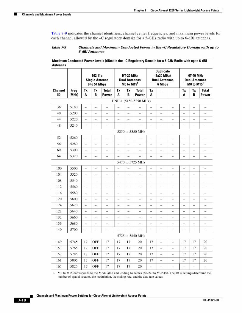
Chapter 7 Cisco Aironet 1250 Series Lightweight Access Points Channels and Maximum Power Levels
Table 7-9 indicates the channel identifiers, channel center frequencies, and maximum power levels for each channel allowed by the –C regulatory domain for a 5-GHz radio with up to 6-dBi antennas.
Table 7-9 Channels and Maximum Conducted Power in the –C Regulatory Domain with up to
6-dBi Antennas
Maximum Conducted Power Levels (dBm) in the –C Regulatory Domain for a 5-GHz Radio with up to 6-dBi Antennas
ChannelID
Freq(MHz)
802.11aSingle Antenna
6 to 54 Mbps
HT-20 MHzDual Antennas
M0 to M151
1. M0 to M15 corresponds to the Modulaton and Coding Schemes (MCS0 to MCS15). The MCS settings determine the number of spatial streams, the modulation, the coding rate, and the data rate values.
Duplicate(2x20 MHz)
Dual Antennas6 Mbps
HT-40 MHzDual Antennas
M0 to M151
TxA
TxB
TotalPower
TxA
TxB
TotalPower
TxA
– – TxA
TxB
TotalPower
UNII-1 (5150-5250 MHz)
36 5180 – – – – – – – – – – – –
40 5200 – – – – – – – – – – – –
44 5220 – – – – – – – – – – – –
48 5240 – – – – – – – – – – – –
5250 to 5350 MHz
52 5260 – – – – – – – – – – – –
56 5280 – – – – – – – – – – – –
60 5300 – – – – – – – – – – – –
64 5320 – – – – – – – – – – – –
5470 to 5725 MHz
100 5500 – – – – – – – – – – – –
104 5520 – – – – – – – – – – – –
108 5540 – – – – – – – – – – – –
112 5560 – – – – – – – – – – – –
116 5580 – – – – – – – – – – – –
120 5600 – – – – – – – – – – – –
124 5620 – – – – – – – – – – – –
128 5640 – – – – – – – – – – – –
132 5660 – – – – – – – – – – – –
136 5680 – – – – – – – – – – – –
140 5700 – – – – – – – – – – – –
5725 to 5850 MHz
149 5745 17 OFF 17 17 17 20 17 – – 17 17 20
153 5765 17 OFF 17 17 17 20 17 – – 17 17 20
157 5785 17 OFF 17 17 17 20 17 – – 17 17 20
161 5805 17 OFF 17 17 17 20 17 – – 17 17 20
165 5825 17 OFF 17 17 17 20 – – – – – –
7-10Channels and Maximum Power Settings for Cisco Aironet Lightweight Access Points
OL-11321-08
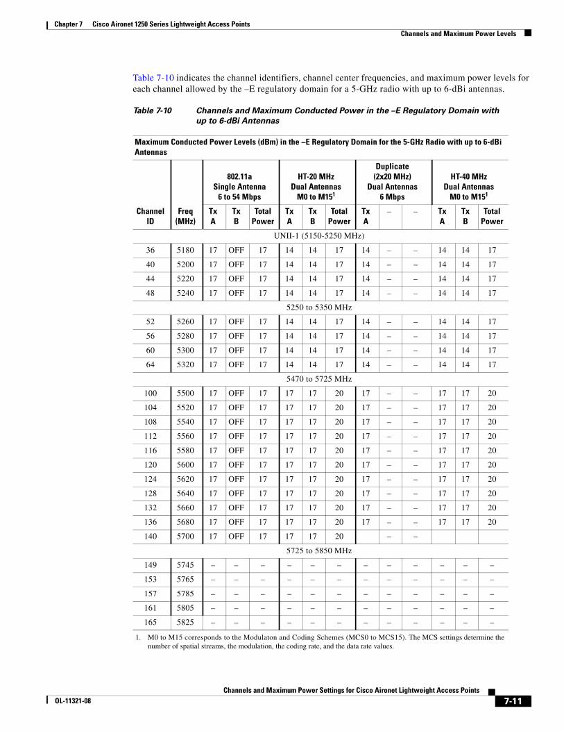
Chapter 7 Cisco Aironet 1250 Series Lightweight Access Points Channels and Maximum Power Levels
Table 7-10 indicates the channel identifiers, channel center frequencies, and maximum power levels for each channel allowed by the –E regulatory domain for a 5-GHz radio with up to 6-dBi antennas.
Table 7-10 Channels and Maximum Conducted Power in the –E Regulatory Domain with
up to 6-dBi Antennas
Maximum Conducted Power Levels (dBm) in the –E Regulatory Domain for the 5-GHz Radio with up to 6-dBi Antennas
ChannelID
Freq(MHz)
802.11aSingle Antenna
6 to 54 Mbps
HT-20 MHzDual Antennas
M0 to M151
1. M0 to M15 corresponds to the Modulaton and Coding Schemes (MCS0 to MCS15). The MCS settings determine the number of spatial streams, the modulation, the coding rate, and the data rate values.
Duplicate(2x20 MHz)
Dual Antennas6 Mbps
HT-40 MHzDual Antennas
M0 to M151
TxA
TxB
TotalPower
TxA
TxB
TotalPower
TxA
– – TxA
TxB
TotalPower
UNII-1 (5150-5250 MHz)
36 5180 17 OFF 17 14 14 17 14 – – 14 14 17
40 5200 17 OFF 17 14 14 17 14 – – 14 14 17
44 5220 17 OFF 17 14 14 17 14 – – 14 14 17
48 5240 17 OFF 17 14 14 17 14 – – 14 14 17
5250 to 5350 MHz
52 5260 17 OFF 17 14 14 17 14 – – 14 14 17
56 5280 17 OFF 17 14 14 17 14 – – 14 14 17
60 5300 17 OFF 17 14 14 17 14 – – 14 14 17
64 5320 17 OFF 17 14 14 17 14 – – 14 14 17
5470 to 5725 MHz
100 5500 17 OFF 17 17 17 20 17 – – 17 17 20
104 5520 17 OFF 17 17 17 20 17 – – 17 17 20
108 5540 17 OFF 17 17 17 20 17 – – 17 17 20
112 5560 17 OFF 17 17 17 20 17 – – 17 17 20
116 5580 17 OFF 17 17 17 20 17 – – 17 17 20
120 5600 17 OFF 17 17 17 20 17 – – 17 17 20
124 5620 17 OFF 17 17 17 20 17 – – 17 17 20
128 5640 17 OFF 17 17 17 20 17 – – 17 17 20
132 5660 17 OFF 17 17 17 20 17 – – 17 17 20
136 5680 17 OFF 17 17 17 20 17 – – 17 17 20
140 5700 17 OFF 17 17 17 20 – –
5725 to 5850 MHz
149 5745 – – – – – – – – – – – –
153 5765 – – – – – – – – – – – –
157 5785 – – – – – – – – – – – –
161 5805 – – – – – – – – – – – –
165 5825 – – – – – – – – – – – –
7-11Channels and Maximum Power Settings for Cisco Aironet Lightweight Access Points
OL-11321-08

Chapter 7 Cisco Aironet 1250 Series Lightweight Access Points Channels and Maximum Power Levels
Table 7-11 indicates the channel identifiers, channel center frequencies, and maximum power levels for each channel allowed by the –I regulatory domain for a 5-GHz radio with up to 6-dBi antenna.s
Table 7-11 Channels and Maximum Conducted Power in the –I Regulatory Domain with up to
6-dBi Antennas
Maximum Conducted Power Levels (dBm) in the –I Regulatory Domain for a 5-GHz Radio with up to 6-dBi Antennas
ChannelID
Freq(MHz)
802.11aSingle Antenna
6 to 54 Mbps
HT-20 MHzDual Antennas
M0 to M151
1. M0 to M15 corresponds to the Modulaton and Coding Schemes (MCS0 to MCS15). The MCS settings determine the number of spatial streams, the modulation, the coding rate, and the data rate values.
Duplicate(2x20 MHz)
Dual Antennas6 Mbps
HT-40 MHzDual Antennas
M0 to M151
TxA
TxB
TotalPower
TxA
TxB
TotalPower
TxA
– – TxA
TxB
TotalPower
UNII-1 (5150-5250 MHz)
36 5180 17 OFF 17 14 14 17 14 – – 14 14 17
40 5200 17 OFF 17 14 14 17 14 – – 14 14 17
44 5220 17 OFF 17 14 14 17 14 – – 14 14 17
48 5240 17 OFF 17 14 14 17 14 – – 14 14 17
5250 to 5350 MHz
52 5260 17 OFF 17 14 14 17 14 – – 14 14 17
56 5280 17 OFF 17 14 14 17 14 – – 14 14 17
60 5300 17 OFF 17 14 14 17 14 – – 14 14 17
64 5320 17 OFF 17 14 14 17 14 – – 14 14 17
5470 to 5725 MHz
100 5500 – – – – – – – – – – – –
104 5520 – – – – – – – – – – – –
108 5540 – – – – – – – – – – – –
112 5560 – – – – – – – – – – – –
116 5580 – – – – – – – – – – – –
120 5600 – – – – – – – – – – – –
124 5620 – – – – – – – – – – – –
128 5640 – – – – – – – – – – – –
132 5660 – – – – – – – – – – – –
136 5680 – – – – – – – – – – – –
140 5700 – – – – – – – – – – – –
5725 to 5850 MHz
149 5745 – – – – – – – – – – – –
153 5765 – – – – – – – – – – – –
157 5785 – – – – – – – – – – – –
161 5805 – – – – – – – – – – – –
165 5825 – – – – – – – – – – – –
7-12Channels and Maximum Power Settings for Cisco Aironet Lightweight Access Points
OL-11321-08

Chapter 7 Cisco Aironet 1250 Series Lightweight Access Points Channels and Maximum Power Levels
Table 7-12 indicates the channel identifiers, channel center frequencies, and maximum power levels for each channel allowed by the –K regulatory domain for a 5-GHz radio with up to 6-dBi antennas.
Table 7-12 Channels and Maximum Conducted Power in the –K Regulatory Domain with
up to 6-dBi Antennas
Maximum Conducted Power Levels (dBm) in the –K Regulatory Domain for a 5-GHz Radio with up to 6-dBi Antennas
ChannelID
Freq(MHz)
802.11aSingle Antenna
6 to 54 Mbps
HT-20 MHzDual Antennas
M0 to M151
1. M0 to M15 corresponds to the Modulaton and Coding Schemes (MCS0 to MCS15). The MCS settings determine the number of spatial streams, the modulation, the coding rate, and the data rate values.
Duplicate(2x20 MHz)
Dual Antennas6 Mbps
HT-40 MHzDual Antennas
M0 to M151
TxA
TxB
TotalPower
TxA
TxB
TotalPower
TxA
– – TxA
TxB
TotalPower
UNII-1 (5150-5250 MHz)
36 5180 14 OFF 14 8 8 11 8 – – 8 8 11
40 5200 14 OFF 14 8 8 11 8 – – 8 8 11
44 5220 14 OFF 14 8 8 11 8 – – 8 8 11
48 5240 14 OFF 14 8 8 11 8 – – 8 8 11
5250 to 5350 MHz
52 5260 17 OFF 17 17 17 20 17 – – 17 17 20
56 5280 17 OFF 17 17 17 20 17 – – 17 17 20
60 5300 17 OFF 17 17 17 20 17 – – 17 17 20
64 5320 17 OFF 17 17 17 20 17 – – 17 17 20
5470 to 5725 MHz
100 5500 17 OFF 17 17 17 20 17 – – 17 17 20
104 5520 17 OFF 17 17 17 20 17 – – 17 17 20
108 5540 17 OFF 17 17 17 20 17 – – 17 17 20
112 5560 17 OFF 17 17 17 20 17 – – 17 17 20
116 5580 17 OFF 17 17 17 20 17 – – 17 17 20
120 5600 17 OFF 17 17 17 20 17 – – 17 17 20
124 5620 17 OFF 17 17 17 20 17 – – – – –
128 5640 – – – – – – – – – – – –
132 5660 – – – – – – – – – – – –
136 5680 – – – – – – – – – – – –
140 5700 – – – – – – – – – – – –
5725 to 5850 MHz
149 5745 17 OFF 17 17 17 20 17 – – 17 17 20
153 5765 17 OFF 17 17 17 20 17 – – 17 17 20
157 5785 17 OFF 17 17 17 20 17 – – 17 17 20
161 5805 17 OFF 17 17 17 20 17 – – 17 17 20
165 5825 – – – – – – – – – – – –
7-13Channels and Maximum Power Settings for Cisco Aironet Lightweight Access Points
OL-11321-08
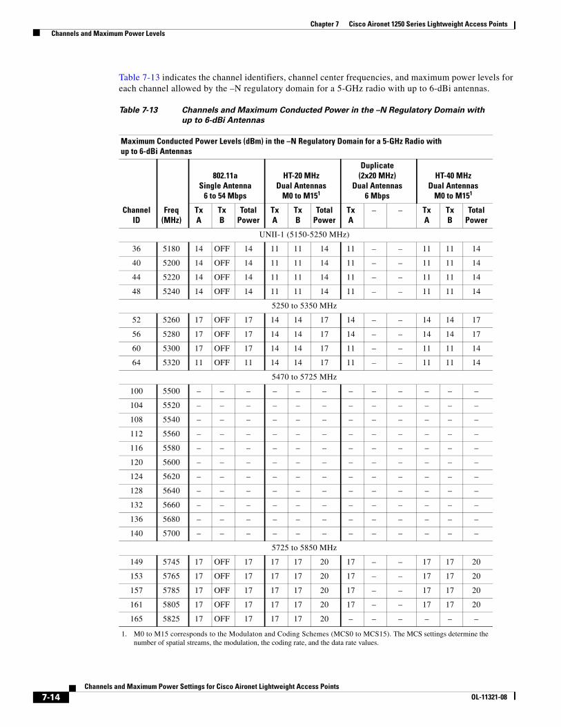
Chapter 7 Cisco Aironet 1250 Series Lightweight Access Points Channels and Maximum Power Levels
Table 7-13 indicates the channel identifiers, channel center frequencies, and maximum power levels for each channel allowed by the –N regulatory domain for a 5-GHz radio with up to 6-dBi antennas.
Table 7-13 Channels and Maximum Conducted Power in the –N Regulatory Domain with
up to 6-dBi Antennas
Maximum Conducted Power Levels (dBm) in the –N Regulatory Domain for a 5-GHz Radio with up to 6-dBi Antennas
ChannelID
Freq(MHz)
802.11aSingle Antenna
6 to 54 Mbps
HT-20 MHzDual Antennas
M0 to M151
1. M0 to M15 corresponds to the Modulaton and Coding Schemes (MCS0 to MCS15). The MCS settings determine the number of spatial streams, the modulation, the coding rate, and the data rate values.
Duplicate(2x20 MHz)
Dual Antennas6 Mbps
HT-40 MHzDual Antennas
M0 to M151
TxA
TxB
TotalPower
TxA
TxB
TotalPower
TxA
– – TxA
TxB
TotalPower
UNII-1 (5150-5250 MHz)
36 5180 14 OFF 14 11 11 14 11 – – 11 11 14
40 5200 14 OFF 14 11 11 14 11 – – 11 11 14
44 5220 14 OFF 14 11 11 14 11 – – 11 11 14
48 5240 14 OFF 14 11 11 14 11 – – 11 11 14
5250 to 5350 MHz
52 5260 17 OFF 17 14 14 17 14 – – 14 14 17
56 5280 17 OFF 17 14 14 17 14 – – 14 14 17
60 5300 17 OFF 17 14 14 17 11 – – 11 11 14
64 5320 11 OFF 11 14 14 17 11 – – 11 11 14
5470 to 5725 MHz
100 5500 – – – – – – – – – – – –
104 5520 – – – – – – – – – – – –
108 5540 – – – – – – – – – – – –
112 5560 – – – – – – – – – – – –
116 5580 – – – – – – – – – – – –
120 5600 – – – – – – – – – – – –
124 5620 – – – – – – – – – – – –
128 5640 – – – – – – – – – – – –
132 5660 – – – – – – – – – – – –
136 5680 – – – – – – – – – – – –
140 5700 – – – – – – – – – – – –
5725 to 5850 MHz
149 5745 17 OFF 17 17 17 20 17 – – 17 17 20
153 5765 17 OFF 17 17 17 20 17 – – 17 17 20
157 5785 17 OFF 17 17 17 20 17 – – 17 17 20
161 5805 17 OFF 17 17 17 20 17 – – 17 17 20
165 5825 17 OFF 17 17 17 20 – – – – – –
7-14Channels and Maximum Power Settings for Cisco Aironet Lightweight Access Points
OL-11321-08

Chapter 7 Cisco Aironet 1250 Series Lightweight Access Points Channels and Maximum Power Levels
Table 7-14 indicates the channel identifiers, channel center frequencies, and maximum power levels for each channel allowed by the –P regulatory domain for a 5-GHz radio with up to 6-dBi antennas.
Table 7-14 Channels and Maximum Conducted Power in the –P Regulatory Domain with up to
6-dBi Antennas
Maximum Conducted Power Levels (dBm) in the –P Regulatory Domain for the 5-GHz Radio with up to 6-dBi Antennas
ChannelID
Freq(MHz)
802.11aSingle Antenna
6 to 54 Mbps
HT-20 MHzDual Antennas
M0 to M151
1. M0 to M15 corresponds to the Modulaton and Coding Schemes (MCS0 to MCS15). The MCS settings determine the number of spatial streams, the modulation, the coding rate, and the data rate values.
Duplicate(2x20 MHz)
Dual Antennas6 Mbps
HT-40 MHzDual Antennas
M0 to M151
TxA
TxB
TotalPower
TxA
TxB
TotalPower
TxA
– – TxA
TxB
TotalPower
UNII-1 (5150-5250 MHz)
36 5180 14 OFF 14 11 11 14 11 – – 11 11 14
40 5200 14 OFF 14 11 11 14 11 – – 11 11 14
44 5220 14 OFF 14 11 11 14 11 – – 11 11 14
48 5240 14 OFF 14 11 11 14 11 – – 11 11 14
5250 to 5350 MHz
52 5260 14 OFF 14 11 11 14 11 – – 11 11 14
56 5280 14 OFF 14 11 11 14 11 – – 11 11 14
60 5300 14 OFF 14 11 11 14 11 – – 11 11 14
64 5320 14 OFF 14 11 11 14 11 – – 11 11 14
5470 to 5725 MHz
100 5500 – – – – – – – – – – – –
104 5520 – – – – – – – – – – – –
108 5540 – – – – – – – – – – – –
112 5560 – – – – – – – – – – – –
116 5580 – – – – – – – – – – – –
120 5600 – – – – – – – – – – – –
124 5620 – – – – – – – – – – – –
128 5640 – – – – – – – – – – – –
132 5660 – – – – – – – – – – – –
136 5680 – – – – – – – – – – – –
140 5700 – – – – – – – – – – – –
5725 to 5850 MHz
149 5745 – – – – – – – – – – – –
153 5765 – – – – – – – – – – – –
157 5785 – – – – – – – – – – – –
161 5805 – – – – – – – – – – – –
165 5825 – – – – – – – – – – – –
7-15Channels and Maximum Power Settings for Cisco Aironet Lightweight Access Points
OL-11321-08
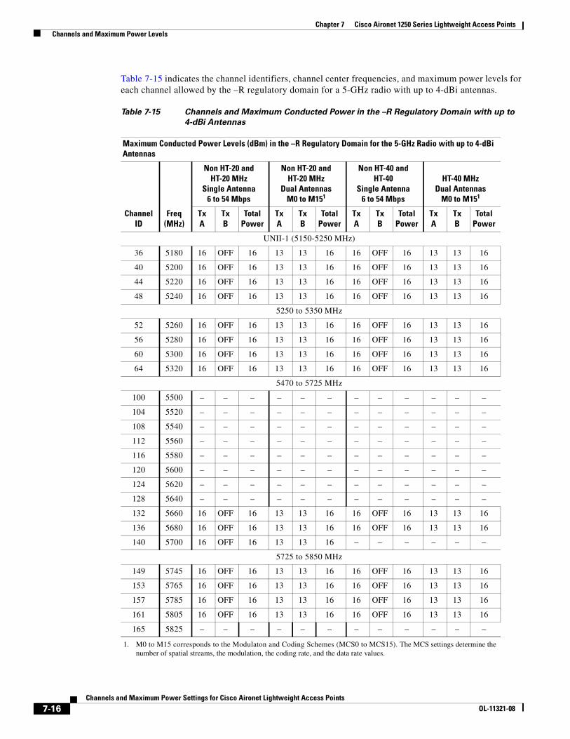
Chapter 7 Cisco Aironet 1250 Series Lightweight Access Points Channels and Maximum Power Levels
Table 7-15 indicates the channel identifiers, channel center frequencies, and maximum power levels for each channel allowed by the –R regulatory domain for a 5-GHz radio with up to 4-dBi antennas.
Table 7-15 Channels and Maximum Conducted Power in the –R Regulatory Domain with up to
4-dBi Antennas
Maximum Conducted Power Levels (dBm) in the –R Regulatory Domain for the 5-GHz Radio with up to 4-dBi Antennas
ChannelID
Freq(MHz)
Non HT-20 and HT-20 MHz
Single Antenna6 to 54 Mbps
Non HT-20 and HT-20 MHz
Dual AntennasM0 to M151
1. M0 to M15 corresponds to the Modulaton and Coding Schemes (MCS0 to MCS15). The MCS settings determine the number of spatial streams, the modulation, the coding rate, and the data rate values.
Non HT-40 and HT-40
Single Antenna6 to 54 Mbps
HT-40 MHzDual Antennas
M0 to M151
TxA
TxB
TotalPower
TxA
TxB
TotalPower
TxA
TxB
TotalPower
TxA
TxB
TotalPower
UNII-1 (5150-5250 MHz)
36 5180 16 OFF 16 13 13 16 16 OFF 16 13 13 16
40 5200 16 OFF 16 13 13 16 16 OFF 16 13 13 16
44 5220 16 OFF 16 13 13 16 16 OFF 16 13 13 16
48 5240 16 OFF 16 13 13 16 16 OFF 16 13 13 16
5250 to 5350 MHz
52 5260 16 OFF 16 13 13 16 16 OFF 16 13 13 16
56 5280 16 OFF 16 13 13 16 16 OFF 16 13 13 16
60 5300 16 OFF 16 13 13 16 16 OFF 16 13 13 16
64 5320 16 OFF 16 13 13 16 16 OFF 16 13 13 16
5470 to 5725 MHz
100 5500 – – – – – – – – – – – –
104 5520 – – – – – – – – – – – –
108 5540 – – – – – – – – – – – –
112 5560 – – – – – – – – – – – –
116 5580 – – – – – – – – – – – –
120 5600 – – – – – – – – – – – –
124 5620 – – – – – – – – – – – –
128 5640 – – – – – – – – – – – –
132 5660 16 OFF 16 13 13 16 16 OFF 16 13 13 16
136 5680 16 OFF 16 13 13 16 16 OFF 16 13 13 16
140 5700 16 OFF 16 13 13 16 – – – – – –
5725 to 5850 MHz
149 5745 16 OFF 16 13 13 16 16 OFF 16 13 13 16
153 5765 16 OFF 16 13 13 16 16 OFF 16 13 13 16
157 5785 16 OFF 16 13 13 16 16 OFF 16 13 13 16
161 5805 16 OFF 16 13 13 16 16 OFF 16 13 13 16
165 5825 – – – – – – – – – – – –
7-16Channels and Maximum Power Settings for Cisco Aironet Lightweight Access Points
OL-11321-08
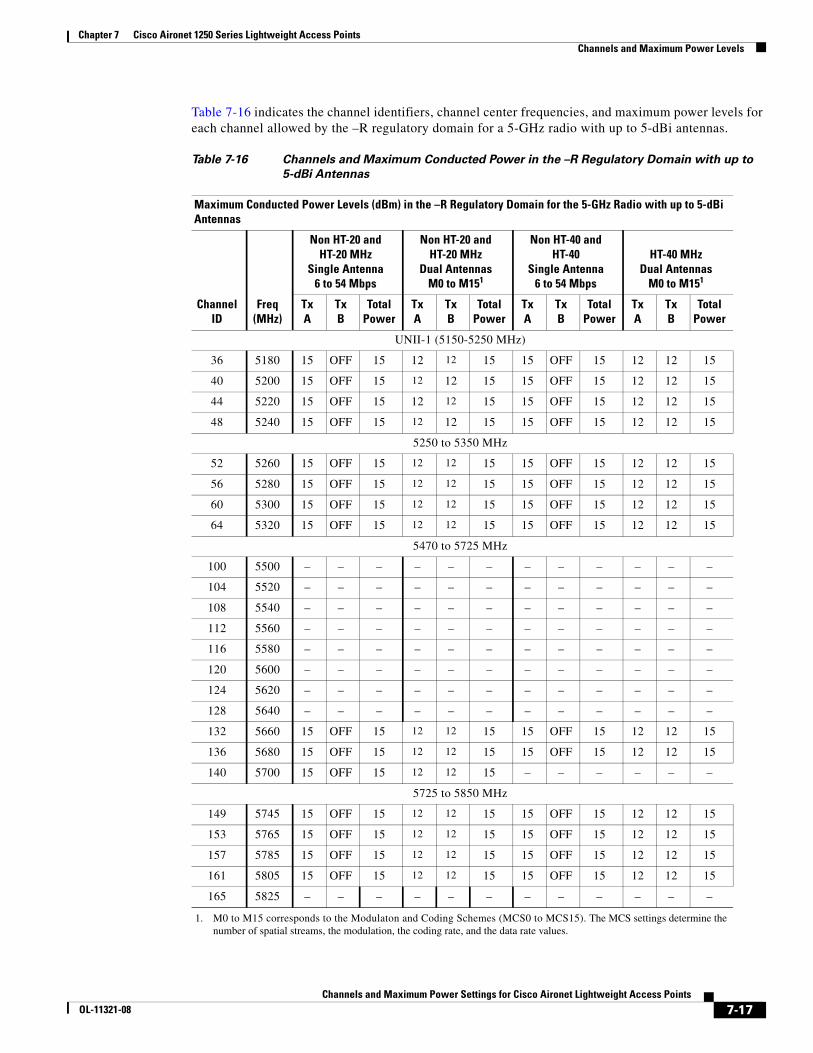
Chapter 7 Cisco Aironet 1250 Series Lightweight Access Points Channels and Maximum Power Levels
Table 7-16 indicates the channel identifiers, channel center frequencies, and maximum power levels for each channel allowed by the –R regulatory domain for a 5-GHz radio with up to 5-dBi antennas.
Table 7-16 Channels and Maximum Conducted Power in the –R Regulatory Domain with up to
5-dBi Antennas
Maximum Conducted Power Levels (dBm) in the –R Regulatory Domain for the 5-GHz Radio with up to 5-dBi Antennas
ChannelID
Freq(MHz)
Non HT-20 and HT-20 MHz
Single Antenna6 to 54 Mbps
Non HT-20 and HT-20 MHz
Dual AntennasM0 to M151
1. M0 to M15 corresponds to the Modulaton and Coding Schemes (MCS0 to MCS15). The MCS settings determine the number of spatial streams, the modulation, the coding rate, and the data rate values.
Non HT-40 and HT-40
Single Antenna6 to 54 Mbps
HT-40 MHzDual Antennas
M0 to M151
TxA
TxB
TotalPower
TxA
TxB
TotalPower
TxA
TxB
TotalPower
TxA
TxB
TotalPower
UNII-1 (5150-5250 MHz)
36 5180 15 OFF 15 12 12 15 15 OFF 15 12 12 15
40 5200 15 OFF 15 12 12 15 15 OFF 15 12 12 15
44 5220 15 OFF 15 12 12 15 15 OFF 15 12 12 15
48 5240 15 OFF 15 12 12 15 15 OFF 15 12 12 15
5250 to 5350 MHz
52 5260 15 OFF 15 12 12 15 15 OFF 15 12 12 15
56 5280 15 OFF 15 12 12 15 15 OFF 15 12 12 15
60 5300 15 OFF 15 12 12 15 15 OFF 15 12 12 15
64 5320 15 OFF 15 12 12 15 15 OFF 15 12 12 15
5470 to 5725 MHz
100 5500 – – – – – – – – – – – –
104 5520 – – – – – – – – – – – –
108 5540 – – – – – – – – – – – –
112 5560 – – – – – – – – – – – –
116 5580 – – – – – – – – – – – –
120 5600 – – – – – – – – – – – –
124 5620 – – – – – – – – – – – –
128 5640 – – – – – – – – – – – –
132 5660 15 OFF 15 12 12 15 15 OFF 15 12 12 15
136 5680 15 OFF 15 12 12 15 15 OFF 15 12 12 15
140 5700 15 OFF 15 12 12 15 – – – – – –
5725 to 5850 MHz
149 5745 15 OFF 15 12 12 15 15 OFF 15 12 12 15
153 5765 15 OFF 15 12 12 15 15 OFF 15 12 12 15
157 5785 15 OFF 15 12 12 15 15 OFF 15 12 12 15
161 5805 15 OFF 15 12 12 15 15 OFF 15 12 12 15
165 5825 – – – – – – – – – – – –
7-17Channels and Maximum Power Settings for Cisco Aironet Lightweight Access Points
OL-11321-08

Chapter 7 Cisco Aironet 1250 Series Lightweight Access Points Channels and Maximum Power Levels
Table 7-17 indicates the channel identifiers, channel center frequencies, and maximum power levels for each channel allowed by the –R regulatory domain for a 5-GHz radio with up to 6-dBi antennas.
Table 7-17 Channels and Maximum Conducted Power in the –R Regulatory Domain with up to
6-dBi Antennas
Maximum Conducted Power Levels (dBm) in the –R Regulatory Domain for the 5-GHz Radio with up to 6-dBi Antennas
ChannelID
Freq(MHz)
Non HT-20 and HT-20 MHz
Single Antenna6 to 54 Mbps
Non HT-20 and HT-20 MHz
Dual AntennasM0 to M151
1. M0 to M15 corresponds to the Modulaton and Coding Schemes (MCS0 to MCS15). The MCS settings determine the number of spatial streams, the modulation, the coding rate, and the data rate values.
Non HT-40 and HT-40
Single Antenna6 to 54 Mbps
HT-40 MHzDual Antennas
M0 to M151
TxA
TxB
TotalPower
TxA
TxB
TotalPower
TxA
TxB
TotalPower
TxA
TxB
TotalPower
UNII-1 (5150-5250 MHz)
36 5180 14 OFF 14 11 11 14 14 OFF 14 11 11 14
40 5200 14 OFF 14 11 11 14 14 OFF 14 11 11 14
44 5220 14 OFF 14 11 11 14 14 OFF 14 11 11 14
48 5240 14 OFF 14 11 11 14 14 OFF 14 11 11 14
5250 to 5350 MHz
52 5260 14 OFF 14 11 11 14 14 OFF 14 11 11 14
56 5280 14 OFF 14 11 11 14 14 OFF 14 11 11 14
60 5300 14 OFF 14 11 11 14 14 OFF 14 11 11 14
64 5320 14 OFF 14 11 11 14 14 OFF 14 11 11 14
5470 to 5725 MHz
100 5500 – – – – – – – – – – – –
104 5520 – – – – – – – – – – – –
108 5540 – – – – – – – – – – – –
112 5560 – – – – – – – – – – – –
116 5580 – – – – – – – – – – – –
120 5600 – – – – – – – – – – – –
124 5620 – – – – – – – – – – – –
128 5640 – – – – – – – – – – – –
132 5660 14 OFF 14 11 11 14 14 OFF 14 11 11 14
136 5680 14 OFF 14 11 11 14 14 OFF 14 11 11 14
140 5700 14 OFF 14 11 11 14 – – – – – –
5725 to 5850 MHz
149 5745 14 OFF 14 11 11 14 14 OFF 14 11 11 14
153 5765 14 OFF 14 11 11 14 14 OFF 14 11 11 14
157 5785 14 OFF 14 11 11 14 14 OFF 14 11 11 14
161 5805 14 OFF 14 11 11 14 14 OFF 14 11 11 14
165 5825 – – – – – – – – – – – –
7-18Channels and Maximum Power Settings for Cisco Aironet Lightweight Access Points
OL-11321-08
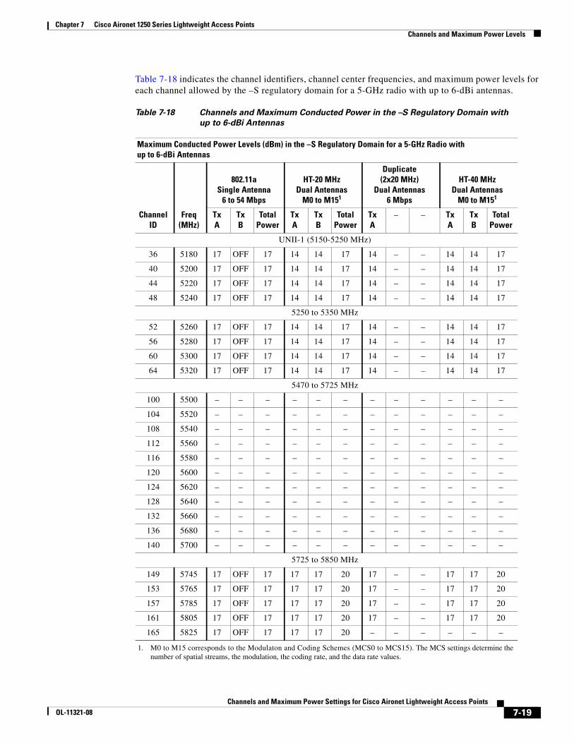
Chapter 7 Cisco Aironet 1250 Series Lightweight Access Points Channels and Maximum Power Levels
Table 7-18 indicates the channel identifiers, channel center frequencies, and maximum power levels for each channel allowed by the –S regulatory domain for a 5-GHz radio with up to 6-dBi antennas.
Table 7-18 Channels and Maximum Conducted Power in the –S Regulatory Domain with
up to 6-dBi Antennas
Maximum Conducted Power Levels (dBm) in the –S Regulatory Domain for a 5-GHz Radio with up to 6-dBi Antennas
ChannelID
Freq(MHz)
802.11aSingle Antenna
6 to 54 Mbps
HT-20 MHzDual Antennas
M0 to M151
1. M0 to M15 corresponds to the Modulaton and Coding Schemes (MCS0 to MCS15). The MCS settings determine the number of spatial streams, the modulation, the coding rate, and the data rate values.
Duplicate(2x20 MHz)
Dual Antennas6 Mbps
HT-40 MHzDual Antennas
M0 to M151
TxA
TxB
TotalPower
TxA
TxB
TotalPower
TxA
– – TxA
TxB
TotalPower
UNII-1 (5150-5250 MHz)
36 5180 17 OFF 17 14 14 17 14 – – 14 14 17
40 5200 17 OFF 17 14 14 17 14 – – 14 14 17
44 5220 17 OFF 17 14 14 17 14 – – 14 14 17
48 5240 17 OFF 17 14 14 17 14 – – 14 14 17
5250 to 5350 MHz
52 5260 17 OFF 17 14 14 17 14 – – 14 14 17
56 5280 17 OFF 17 14 14 17 14 – – 14 14 17
60 5300 17 OFF 17 14 14 17 14 – – 14 14 17
64 5320 17 OFF 17 14 14 17 14 – – 14 14 17
5470 to 5725 MHz
100 5500 – – – – – – – – – – – –
104 5520 – – – – – – – – – – – –
108 5540 – – – – – – – – – – – –
112 5560 – – – – – – – – – – – –
116 5580 – – – – – – – – – – – –
120 5600 – – – – – – – – – – – –
124 5620 – – – – – – – – – – – –
128 5640 – – – – – – – – – – – –
132 5660 – – – – – – – – – – – –
136 5680 – – – – – – – – – – – –
140 5700 – – – – – – – – – – – –
5725 to 5850 MHz
149 5745 17 OFF 17 17 17 20 17 – – 17 17 20
153 5765 17 OFF 17 17 17 20 17 – – 17 17 20
157 5785 17 OFF 17 17 17 20 17 – – 17 17 20
161 5805 17 OFF 17 17 17 20 17 – – 17 17 20
165 5825 17 OFF 17 17 17 20 – – – – – –
7-19Channels and Maximum Power Settings for Cisco Aironet Lightweight Access Points
OL-11321-08
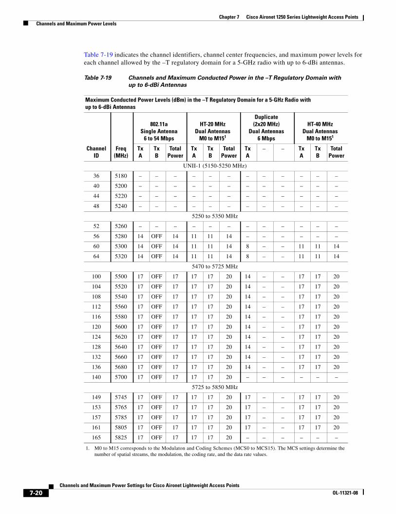
Chapter 7 Cisco Aironet 1250 Series Lightweight Access Points Channels and Maximum Power Levels
Table 7-19 indicates the channel identifiers, channel center frequencies, and maximum power levels for each channel allowed by the –T regulatory domain for a 5-GHz radio with up to 6-dBi antennas.
Table 7-19 Channels and Maximum Conducted Power in the –T Regulatory Domain with
up to 6-dBi Antennas
Maximum Conducted Power Levels (dBm) in the –T Regulatory Domain for a 5-GHz Radio with up to 6-dBi Antennas
ChannelID
Freq(MHz)
802.11aSingle Antenna
6 to 54 Mbps
HT-20 MHzDual Antennas
M0 to M151
1. M0 to M15 corresponds to the Modulaton and Coding Schemes (MCS0 to MCS15). The MCS settings determine the number of spatial streams, the modulation, the coding rate, and the data rate values.
Duplicate(2x20 MHz)
Dual Antennas6 Mbps
HT-40 MHzDual Antennas
M0 to M151
TxA
TxB
TotalPower
TxA
TxB
TotalPower
TxA
– – TxA
TxB
TotalPower
UNII-1 (5150-5250 MHz)
36 5180 – – – – – – – – – – – –
40 5200 – – – – – – – – – – – –
44 5220 – – – – – – – – – – – –
48 5240 – – – – – – – – – – – –
5250 to 5350 MHz
52 5260 – – – – – – – – – – – –
56 5280 14 OFF 14 11 11 14 – – – – – –
60 5300 14 OFF 14 11 11 14 8 – – 11 11 14
64 5320 14 OFF 14 11 11 14 8 – – 11 11 14
5470 to 5725 MHz
100 5500 17 OFF 17 17 17 20 14 – – 17 17 20
104 5520 17 OFF 17 17 17 20 14 – – 17 17 20
108 5540 17 OFF 17 17 17 20 14 – – 17 17 20
112 5560 17 OFF 17 17 17 20 14 – – 17 17 20
116 5580 17 OFF 17 17 17 20 14 – – 17 17 20
120 5600 17 OFF 17 17 17 20 14 – – 17 17 20
124 5620 17 OFF 17 17 17 20 14 – – 17 17 20
128 5640 17 OFF 17 17 17 20 14 – – 17 17 20
132 5660 17 OFF 17 17 17 20 14 – – 17 17 20
136 5680 17 OFF 17 17 17 20 14 – – 17 17 20
140 5700 17 OFF 17 17 17 20 – – – – – –
5725 to 5850 MHz
149 5745 17 OFF 17 17 17 20 17 – – 17 17 20
153 5765 17 OFF 17 17 17 20 17 – – 17 17 20
157 5785 17 OFF 17 17 17 20 17 – – 17 17 20
161 5805 17 OFF 17 17 17 20 17 – – 17 17 20
165 5825 17 OFF 17 17 17 20 – – – – – –
7-20Channels and Maximum Power Settings for Cisco Aironet Lightweight Access Points
OL-11321-08
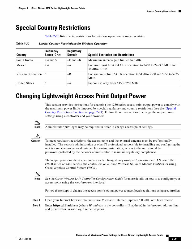
Chapter 7 Cisco Aironet 1250 Series Lightweight Access Points Special Country Restrictions
Special Country RestrictionsTable 7-20 lists special restrictions for wireless operation in some countries.
Changing Lightweight Access Point Output PowerThis section provides instructions for changing the 1250 series access point output power to comply with the maximum power limits imposed by special regulatory and country restrictions (see the “Special Country Restrictions” section on page 7-21). Follow these instructions to change the output power settings using a controller and your browser:
Note Administrator privileges may be required in order to change access point settings.
Caution To meet regulatory restrictions, the access point and the external antenna must be professionally installed. The network administration or other IT professional responsible for installing and configuring the unit is a suitable professional installer. Following installation, access to the unit should be password-protected by the network administrator to maintain regulatory compliance.
The output power on the access points can be changed only using a Cisco wireless LAN controller(2600 series or 4400 series), the controllers on a Cisco Wireless Services Module (WiSM), or using Cisco Wireless Control System (WCS).
Note See the Cisco Wireless LAN Controller Configuration Guide for more details on how to to configure your access point using the web-browser interface.
Follow these steps to change the access point’s output power to meet local regulations using a controller:
Step 1 Open your Internet browser. You must use Microsoft Internet Explorer 6.0.2800 or a later release.
Step 2 Enter https://IP address (where IP address is the controller’s IP address) in the browser address line and press Enter. A user login screen appears.
Table 7-20 Special Country Restrictions for Wireless Operation
CountryFrequency Bands (GHz)
Regulatory Domain Special Limitation and Restrictions
South Korea 2.4 and 5 –E and –K Maximum antenna gain limited to 6 dBi.
Mexico 2.4 –A End user must limit 2.4 GHz operation to 2450 to 2483.5 MHz and 36 dBm EIRP.
Russian Federation 5 –R End user must limit 5 GHz operation to 5150 to 5350 and 5650 to 5725 MHz.
United States 5 –A Indoor use only from 5150-5250 MHz.
7-21Channels and Maximum Power Settings for Cisco Aironet Lightweight Access Points
OL-11321-08
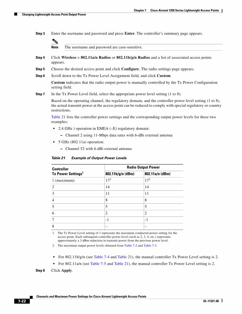
Chapter 7 Cisco Aironet 1250 Series Lightweight Access Points Changing Lightweight Access Point Output Power
Step 3 Enter the username and password and press Enter. The controller’s summary page appears.
Note The username and password are case-sensitive.
Step 4 Click Wireless > 802.11a/n Radios or 802.11b/g/n Radios and a list of associated access points appears.
Step 5 Choose the desired access point and click Configure. The radio settings page appears.
Step 6 Scroll down to the Tx Power Level Assignment field, and click Custom.
Custom indicates that the radio output power is manually controlled by the Tx Power Configuration setting field.
Step 7 In the Tx Power Level field, select the appropriate power level setting (1 to 8).
Based on the operating channel, the regulatory domain, and the controller power level setting (1 to 8), the actual transmit power at the access point can be reduced to comply with special regulatory or country restrictions.
Table 21 lists the controller power settings and the corresponding output power levels for these two examples:
• 2.4 GHz ) operation in EMEA (–E) regulatory domain:
– Channel 2 using 11-Mbps data rates with 6-dBi external antenna
• 5 GHz (802.11a) operation:
– Channel 52 with 6-dBi external antenna
• For 802.11b/g/n (see Table 7-4 and Table 21), the manual controller Tx Power Level setting is 2.
• For 802.11a/n (see Table 7-5 and Table 21), the manual controller Tx Power Level setting is 2.
Step 8 Click Apply.
Table 21 Example of Output Power Levels
Controller Tx Power Settings1
1. The Tx Power Level setting of 1 represents the maximum conducted power setting for the access point. Each subsequent controller power level (such as 2, 3, 4, etc.) represents approximately a 3-dBm reduction in transmit power from the previous power level.
Radio Output Power
802.11b/g/n (dBm) 802.11a/n (dBm)
1 (maximum) 172
2. The maximum output power levels obtained from Table 7-2 and Table 7-3.
172
2 14 14
3 11 11
4 8 8
5 5 5
6 2 2
7 -1 -1
8 – –
7-22Channels and Maximum Power Settings for Cisco Aironet Lightweight Access Points
OL-11321-08
Chapter 7 Cisco Aironet 1250 Series Lightweight Access Points Changing Lightweight Access Point Output Power
Step 9 Close your Internet browser.
7-23Channels and Maximum Power Settings for Cisco Aironet Lightweight Access Points
OL-11321-08
Chapter 7 Cisco Aironet 1250 Series Lightweight Access Points Changing Lightweight Access Point Output Power
7-24Channels and Maximum Power Settings for Cisco Aironet Lightweight Access Points
OL-11321-08

Channels and Maximum Power SeOL-11321-08
C H A P T E R 8
Cisco Aironet 1300 Series Access PointsThis chapter lists the lightweight access point (model: AIR-LAP1310G) IEEE 802.11b/g 2.4-GHz channels, maximum power levels, and antenna gains supported by the world’s regulatory domains. For additional product hardware information refer to the Cisco Aironet 1300 Series Outdoor Access Point/Bridge Hardware Installation Guide.
The following topics are covered in this chapter:
• Channels, page 8-2
• Maximum Power Levels and Antenna Gains, page 8-3
• Changing the Lightweight Access Point Output Power, page 8-4
• Power Conversion Table, page 8-6
8-1ttings for Cisco Aironet Lightweight Access Points
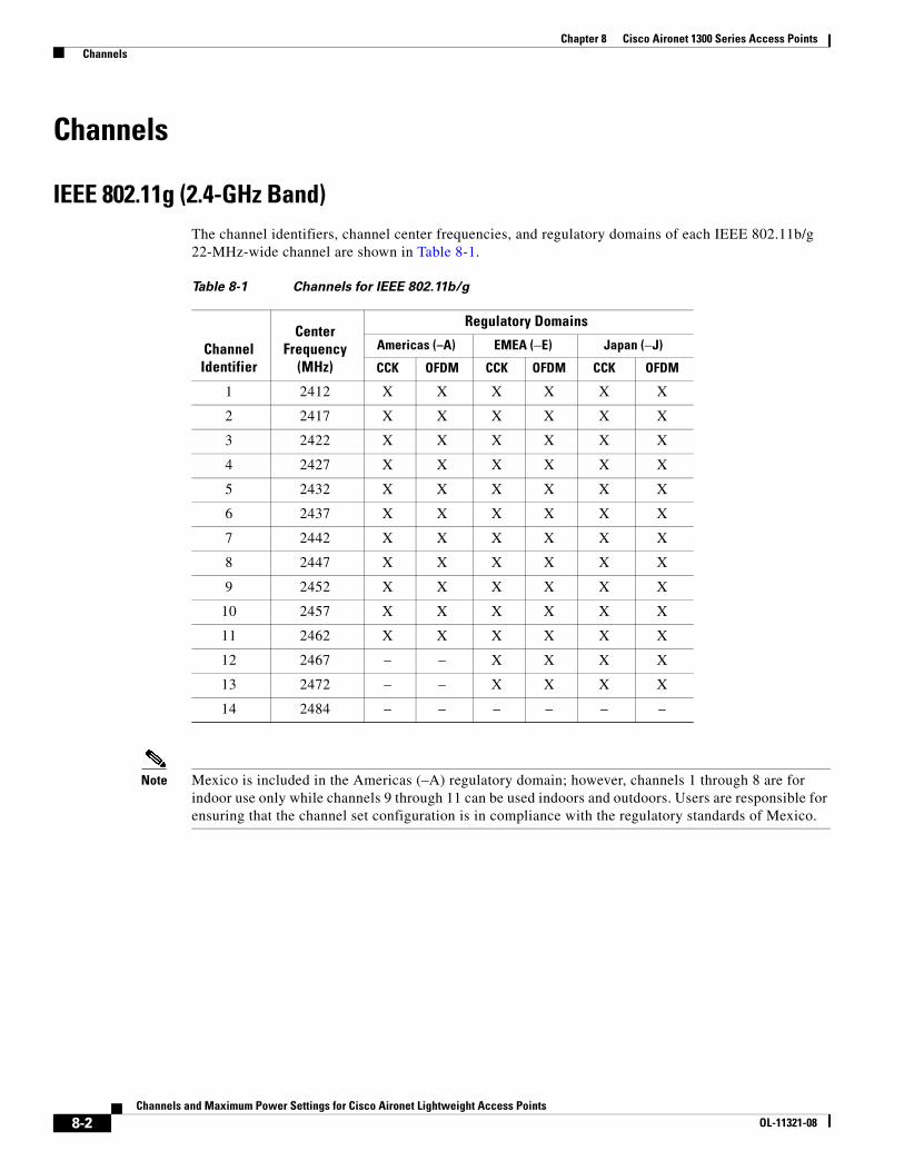
Chapter 8 Cisco Aironet 1300 Series Access Points Channels
Channels
IEEE 802.11g (2.4-GHz Band)The channel identifiers, channel center frequencies, and regulatory domains of each IEEE 802.11b/g 22-MHz-wide channel are shown in Table 8-1.
Note Mexico is included in the Americas (–A) regulatory domain; however, channels 1 through 8 are for indoor use only while channels 9 through 11 can be used indoors and outdoors. Users are responsible for ensuring that the channel set configuration is in compliance with the regulatory standards of Mexico.
Table 8-1 Channels for IEEE 802.11b/g
Channel Identifier
Center Frequency
(MHz)
Regulatory Domains
Americas (–A) EMEA (–E) Japan (–J)
CCK OFDM CCK OFDM CCK OFDM
1 2412 X X X X X X
2 2417 X X X X X X
3 2422 X X X X X X
4 2427 X X X X X X
5 2432 X X X X X X
6 2437 X X X X X X
7 2442 X X X X X X
8 2447 X X X X X X
9 2452 X X X X X X
10 2457 X X X X X X
11 2462 X X X X X X
12 2467 – – X X X X
13 2472 – – X X X X
14 2484 – – – – – –
8-2Channels and Maximum Power Settings for Cisco Aironet Lightweight Access Points
OL-11321-08
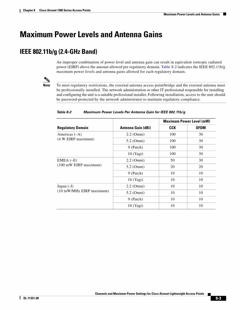
Chapter 8 Cisco Aironet 1300 Series Access Points Maximum Power Levels and Antenna Gains
Maximum Power Levels and Antenna Gains
IEEE 802.11b/g (2.4-GHz Band)An improper combination of power level and antenna gain can result in equivalent isotropic radiated power (EIRP) above the amount allowed per regulatory domain. Table 8-2 indicates the IEEE 802.11b/g maximum power levels and antenna gains allowed for each regulatory domain.
Note To meet regulatory restrictions, the external antenna access point/bridge and the external antenna must be professionally installed. The network administration or other IT professional responsible for installing and configuring the unit is a suitable professional installer. Following installation, access to the unit should be password-protected by the network administrator to maintain regulatory compliance.
Table 8-2 Maximum Power Levels Per Antenna Gain for IEEE 802.11b/g
Regulatory Domain Antenna Gain (dBi)
Maximum Power Level (mW)
CCK OFDM
Americas (–A)(4 W EIRP maximum)
2.2 (Omni) 100 30
5.2 (Omni) 100 30
9 (Patch) 100 30
10 (Yagi) 100 30
EMEA (–E) (100 mW EIRP maximum)
2.2 (Omni) 50 30
5.2 (Omni) 20 20
9 (Patch) 10 10
10 (Yagi) 10 10
Japan (-J)(10 mW/MHz EIRP maximum)
2.2 (Omni) 10 10
5.2 (Omni) 10 10
9 (Patch) 10 10
10 (Yagi) 10 10
8-3Channels and Maximum Power Settings for Cisco Aironet Lightweight Access Points
OL-11321-08

Chapter 8 Cisco Aironet 1300 Series Access Points Changing the Lightweight Access Point Output Power
Changing the Lightweight Access Point Output PowerThis section provides instructions for changing the 1300 series lightweight access point output power to comply with the maximum power limits imposed by regulatory domains (see the “Maximum Power Levels and Antenna Gains” section on page 8-3). Follow these instructions to change the output power settings using your browser:
Note Administrator privileges may be required in order to change access point settings.
Note Regulatory domains are set at the factory and cannot be changed by the user.
The output power on the AIR-LAP1310G-x-K9 (where x is the regulatory domain) access points can be changed only by using a Cisco wireless LAN controller (2600 series or 4400 series), the controllers on a Cisco Wireless Services Module (WiSM), or using Cisco Wireless Control System (WCS).
Note See the Cisco Wireless LAN Controller Configuration Guide for more details on how to configure your access point using the web-browser interface.
Follow these steps to change the AIR-LAP1310G-x-K9 (where x is the regulatory domain) access point’s output power to meet local regulations using a controller:
Step 1 Open your Internet browser. You must use Microsoft Internet Explorer 6.0.2800 or a later release.
Step 2 Enter https://IP address (where IP address is the controller’s IP address) in the browser address line and press Enter. A user login screen appears.
Step 3 Enter the username and password and press Enter. The controller’s summary page appears.
Note The username and password are case-sensitive.
Step 4 Click Wireless > 802.11b/g Radio and a list of associated access points appears.
Step 5 Choose the desired access point from the displayed list and click Configure. The radio settings page appears.
Step 6 Scroll down to the Tx Power Level Assignment field, and click Custom. Custom indicates that the radio output power is manually controlled by the Tx Power Configuration setting field.
8-4Channels and Maximum Power Settings for Cisco Aironet Lightweight Access Points
OL-11321-08

Chapter 8 Cisco Aironet 1300 Series Access Points Changing the Lightweight Access Point Output Power
Step 7 In the Tx Power Level field, select the appropriate power level setting (1 to 8).
Based on the configured antenna gain, the configured channel, and the configured power level, the actual transmit power at the access point can be reduced so that the specific country regulations are not exceeded.
Table 8-3 lists the controller power settings and the corresponding output power levels for this example:
• 2.4-GHz (802.11b/g) operation:
– EMEA (–E) regulatory domain and channel 2
– 5.2-dBi external antenna
• The manual controller Tx Power Level setting is 3 for 802.11b (CCK) data rates (see Table 8-2).
• The manual controller Tx Power Level setting is 2 for only 802.11g (OFDM) data rates (see Table 8-2).
Step 8 Click Apply.
Step 9 Close your Internet browser.
For additional configuration information, refer to the Cisco Wireless LAN Controller Configuration Guide.
Table 8-3 Available Output Power Levels
Controller Tx Power Settings1
1. The Tx Power Level setting of 1 represents the maximum conducted power setting for the access point. Each subsequent power level (such as 2, 3, 4, etc.) represents an approximate 3-dBm reduction in transmit power from the previous power level.
Radio Output Power
802.11b (mW) 802.11g (mW)
1 (maximum)2
2. See Table 8-2 for the maximum power levels in the –E regulatory domain.
50 30
2 25 15
3 12 8
4 6 4
5 3 2
6 2 1
7 -1 –
8 –
8-5Channels and Maximum Power Settings for Cisco Aironet Lightweight Access Points
OL-11321-08

Chapter 8 Cisco Aironet 1300 Series Access Points Power Conversion Table
Power Conversion TableYou can use Table 8-4 to convert power values from dBm to mW or from mW to dBm.
Table 8-4 Power Conversion Table
mW dBm mW dBm mW dBm
200 23 40 16 8 9
150 22 30 15 6 8
125 21 25 14 5 7
100 20 20 13 4 6
80 19 15 12 3 5
60 18 12 11 2 2
50 17 10 10 1 –1
8-6Channels and Maximum Power Settings for Cisco Aironet Lightweight Access Points
OL-11321-08
Channels and Maximum Power SeOL-11321-08
C H A P T E R 9
Cisco Aironet 1500 Series Mesh Access PointsThis chapter lists the 1500 series mesh access point IEEE 802.11b/g (2.4-GHz) and IEEE 802.11a (5-GHz) channels and the maximum power levels supported by the world’s regulatory domains. For additional product hardware information refer to the Cisco Aironet 1500 Series Outdoor Mesh Access Point Hardware Installation Guide.
The AIR-LAP1510 access point model supports both 802.11b/g and 802.11a radios. The AIR-LAP1505 access point model only supports a 802.11b/g radio.
The following topics are covered in this chapter:
• Channels and Maximum Power Levels, page 9-2
• Antenna Settings, page 9-5
• Special Country Restrictions, page 9-7
9-1ttings for Cisco Aironet Lightweight Access Points

Chapter 9 Cisco Aironet 1500 Series Mesh Access Points Channels and Maximum Power Levels
Channels and Maximum Power Levels
IEEE 802.11b/g (2.4-GHz Band)When shipped from the factory, the access points support the channels and maximum power levels listed in Table 9-1 for their regulatory domain.
Note In Table 9-1, the operating data rates (in Mbps) are shown in the CCK and OFDM table cells. For example: CCK 1-11 indicates CCK data rates of 1 to 11 Mbps and All indicates all CCK and OFDM data rates.
Note The AIR-LAP1505 access point model only supports the –A, –E, and –P regulatory domains.
Table 9-1 Channels and Maximum Conducted Power for the 802.11b/g Radio with Up to 8-dBi Antennas
Channel ID
Center Freq
(MHz)
Maximum Conducted Power Levels (dBm) in the Regulatory Domains
–A –C –E –K –N –S –P
CCK1-11
OFDM6-36
OFDM48
OFDM54 All All All
CCK1-11
OFDM6-36
OFDM48
OFDM54
CCK1-11
OFDM6-36
OFDM48
OFDM54 All
1 2412 23 19.5 19.5 19.5 14 14 14 23 19.5 19.5 19.5 17 17 16 15 14
2 2417 23.5 21.5 21.5 21 14 14 14 23.5 21.5 21.5 21 17 17 16 15 14
3 2422 24 23 22 21 14 14 14 24 23 22 21 17 17 16 15 14
4 2427 24 24 22 21 14 14 14 24 24 22 21 17 17 16 15 14
5 2432 24 24 22 21 14 14 14 24 24 22 21 17 17 16 15 14
6 2437 24 24 22 21 14 14 14 24 24 22 21 17 17 16 15 14
7 2442 24 24 22 21 14 14 14 24 24 22 21 17 17 16 15 14
8 2447 24 24 22 21 14 14 14 24 24 22 21 17 17 16 15 14
9 2452 24 22.5 22 21 14 14 14 24 22.5 22 21 17 17 16 15 14
10 2457 23.5 21.5 21.5 21 14 14 14 23.5 21.5 21.5 21 17 17 16 15 14
11 2462 23 19.5 19.5 19.5 14 14 14 23 19.5 19.5 19.5 17 17 16 15 14
12 2467 – – – – 14 14 14 – – – 17 17 16 15 14
13 2472 – – – – 14 14 14 – – – 17 17 16 15 14
14 2484 – – – – – – – – – – – – – – – 14
9-2Channels and Maximum Power Settings for Cisco Aironet Lightweight Access Points
OL-11321-08
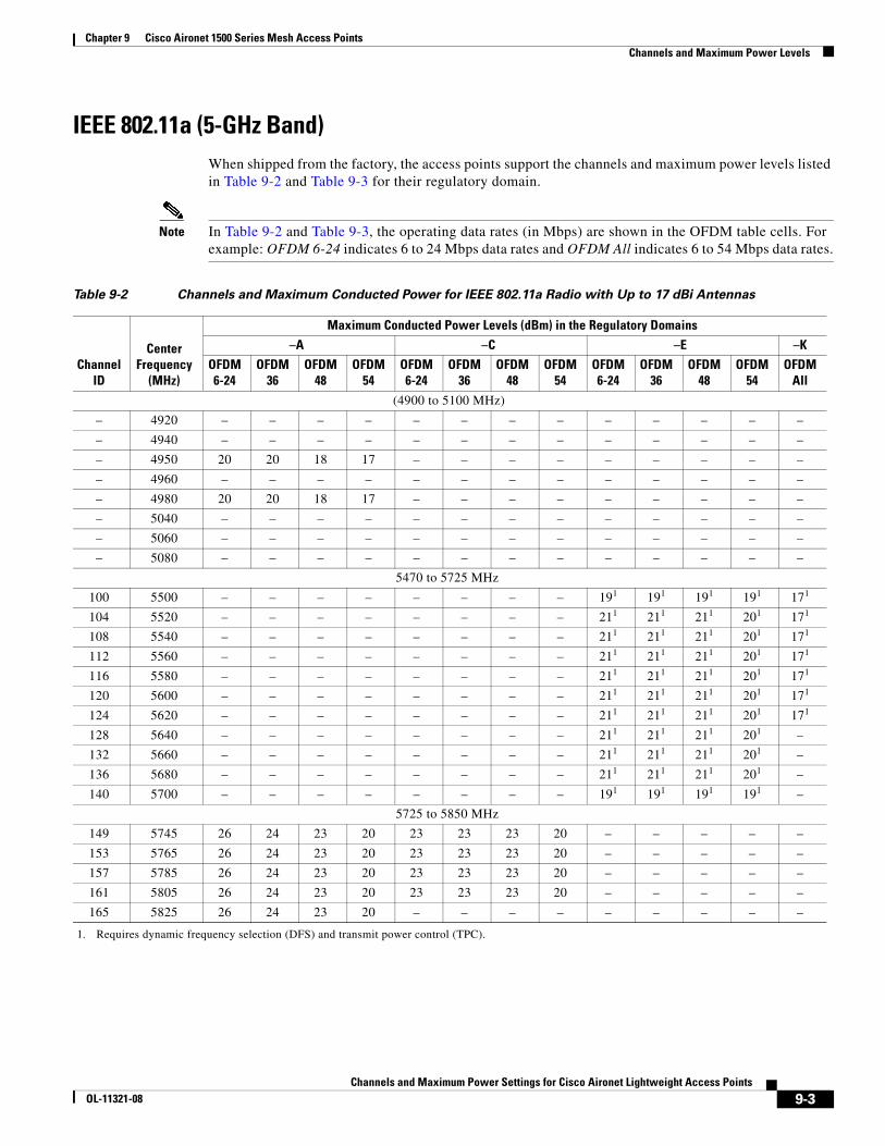
Chapter 9 Cisco Aironet 1500 Series Mesh Access Points Channels and Maximum Power Levels
IEEE 802.11a (5-GHz Band)When shipped from the factory, the access points support the channels and maximum power levels listed in Table 9-2 and Table 9-3 for their regulatory domain.
Note In Table 9-2 and Table 9-3, the operating data rates (in Mbps) are shown in the OFDM table cells. For example: OFDM 6-24 indicates 6 to 24 Mbps data rates and OFDM All indicates 6 to 54 Mbps data rates.
Table 9-2 Channels and Maximum Conducted Power for IEEE 802.11a Radio with Up to 17 dBi Antennas
ChannelID
Center Frequency
(MHz)
Maximum Conducted Power Levels (dBm) in the Regulatory Domains–A –C –E –K
OFDM6-24
OFDM36
OFDM48
OFDM54
OFDM6-24
OFDM36
OFDM48
OFDM54
OFDM6-24
OFDM36
OFDM48
OFDM54
OFDMAll
(4900 to 5100 MHz)
– 4920 – – – – – – – – – – – – –
– 4940 – – – – – – – – – – – – –
– 4950 20 20 18 17 – – – – – – – – –
– 4960 – – – – – – – – – – – – –
– 4980 20 20 18 17 – – – – – – – – –
– 5040 – – – – – – – – – – – – –
– 5060 – – – – – – – – – – – – –
– 5080 – – – – – – – – – – – – –
5470 to 5725 MHz
100 5500 – – – – – – – – 191
1. Requires dynamic frequency selection (DFS) and transmit power control (TPC).
191 191 191 171
104 5520 – – – – – – – – 211 211 211 201 171
108 5540 – – – – – – – – 211 211 211 201 171
112 5560 – – – – – – – – 211 211 211 201 171
116 5580 – – – – – – – – 211 211 211 201 171
120 5600 – – – – – – – – 211 211 211 201 171
124 5620 – – – – – – – – 211 211 211 201 171
128 5640 – – – – – – – – 211 211 211 201 –
132 5660 – – – – – – – – 211 211 211 201 –
136 5680 – – – – – – – – 211 211 211 201 –
140 5700 – – – – – – – – 191 191 191 191 –
5725 to 5850 MHz
149 5745 26 24 23 20 23 23 23 20 – – – – –
153 5765 26 24 23 20 23 23 23 20 – – – – –
157 5785 26 24 23 20 23 23 23 20 – – – – –
161 5805 26 24 23 20 23 23 23 20 – – – – –
165 5825 26 24 23 20 – – – – – – – – –
9-3Channels and Maximum Power Settings for Cisco Aironet Lightweight Access Points
OL-11321-08
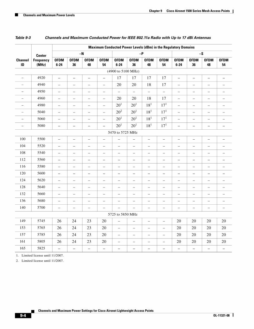
Chapter 9 Cisco Aironet 1500 Series Mesh Access Points Channels and Maximum Power Levels
Table 9-3 Channels and Maximum Conducted Power for IEEE 802.11a Radio with Up to 17 dBi Antennas
ChannelID
Center Frequency
(MHz)
Maximum Conducted Power Levels (dBm) in the Regulatory Domains
–N –P –S
OFDM6-24
OFDM36
OFDM48
OFDM54
OFDM6-24
OFDM36
OFDM48
OFDM54
OFDM6-24
OFDM36
OFDM48
OFDM54
(4900 to 5100 MHz)
– 4920 – – – – 17 17 17 17 – – – –
– 4940 – – – – 20 20 18 17 – – – –
– 4950 – – – – – – – – – – – –
– 4960 – – – – 20 20 18 17 – – – –
– 4980 – – – – 201
1. Limited license until 11/2007.
201 181 171 – – – –
– 5040 – – – – 202
2. Limited license until 11/2007.
201 181 171 – – – –
– 5060 – – – – 201 201 181 171 – – – –
– 5080 – – – – 201 201 181 171 – – – –
5470 to 5725 MHz
100 5500 – – – – – – – – – – – –
104 5520 – – – – – – – – – – – –
108 5540 – – – – – – – – – – – –
112 5560 – – – – – – – – – – – –
116 5580 – – – – – – – – – – – –
120 5600 – – – – – – – – – – – –
124 5620 – – – – – – – – – – – –
128 5640 – – – – – – – – – – – –
132 5660 – – – – – – – – – – – –
136 5680 – – – – – – – – – – – –
140 5700 – – – – – – – – – – – –
5725 to 5850 MHz
149 5745 26 24 23 20 – – – – 20 20 20 20
153 5765 26 24 23 20 – – – – 20 20 20 20
157 5785 26 24 23 20 – – – – 20 20 20 20
161 5805 26 24 23 20 – – – – 20 20 20 20
165 5825 – – – – – – – – – – – –
9-4Channels and Maximum Power Settings for Cisco Aironet Lightweight Access Points
OL-11321-08
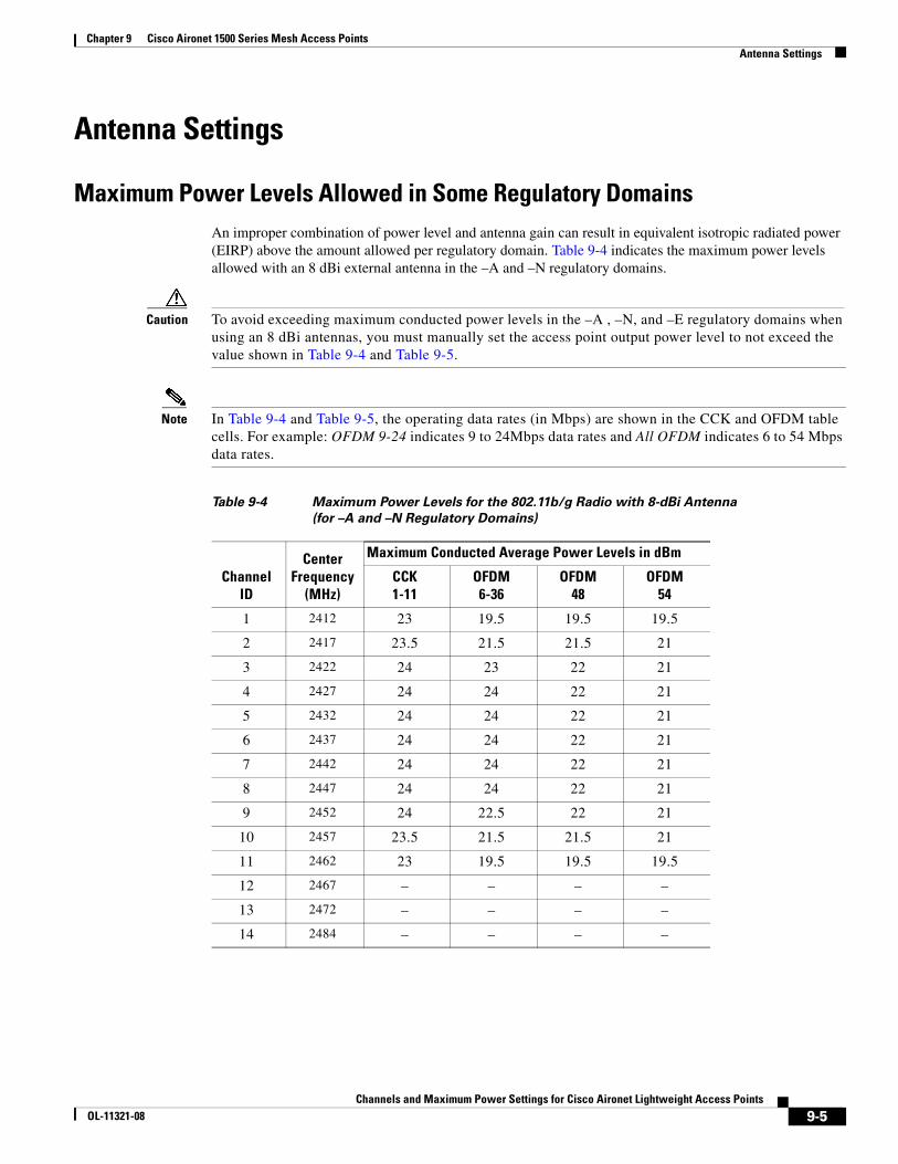
Chapter 9 Cisco Aironet 1500 Series Mesh Access Points Antenna Settings
Antenna Settings
Maximum Power Levels Allowed in Some Regulatory DomainsAn improper combination of power level and antenna gain can result in equivalent isotropic radiated power (EIRP) above the amount allowed per regulatory domain. Table 9-4 indicates the maximum power levels allowed with an 8 dBi external antenna in the –A and –N regulatory domains.
Caution To avoid exceeding maximum conducted power levels in the –A , –N, and –E regulatory domains when using an 8 dBi antennas, you must manually set the access point output power level to not exceed the value shown in Table 9-4 and Table 9-5.
Note In Table 9-4 and Table 9-5, the operating data rates (in Mbps) are shown in the CCK and OFDM table cells. For example: OFDM 9-24 indicates 9 to 24Mbps data rates and All OFDM indicates 6 to 54 Mbps data rates.
Table 9-4 Maximum Power Levels for the 802.11b/g Radio with 8-dBi Antenna
(for –A and –N Regulatory Domains)
ChannelID
CenterFrequency
(MHz)
Maximum Conducted Average Power Levels in dBm
CCK1-11
OFDM6-36
OFDM48
OFDM54
1 2412 23 19.5 19.5 19.5
2 2417 23.5 21.5 21.5 21
3 2422 24 23 22 21
4 2427 24 24 22 21
5 2432 24 24 22 21
6 2437 24 24 22 21
7 2442 24 24 22 21
8 2447 24 24 22 21
9 2452 24 22.5 22 21
10 2457 23.5 21.5 21.5 21
11 2462 23 19.5 19.5 19.5
12 2467 – – – –
13 2472 – – – –
14 2484 – – – –
9-5Channels and Maximum Power Settings for Cisco Aironet Lightweight Access Points
OL-11321-08
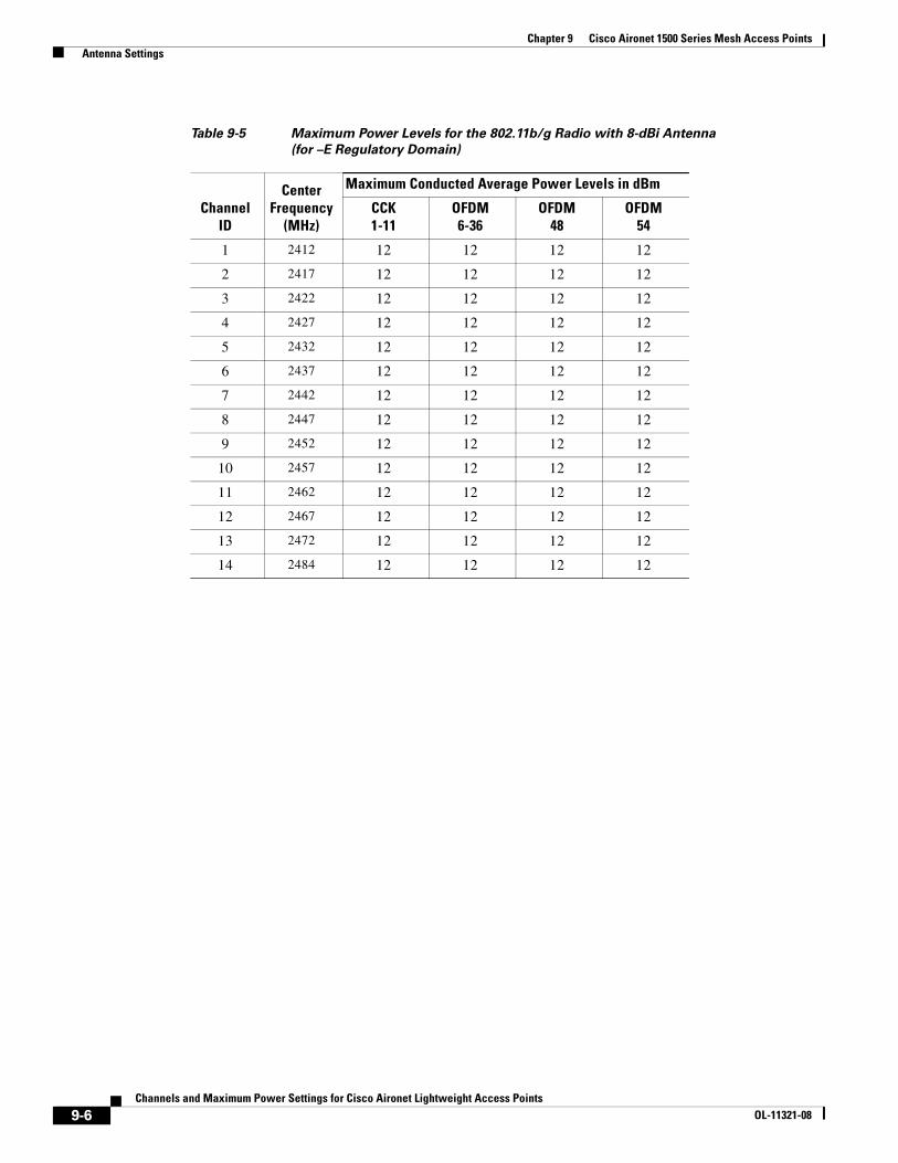
Chapter 9 Cisco Aironet 1500 Series Mesh Access Points Antenna Settings
Table 9-5 Maximum Power Levels for the 802.11b/g Radio with 8-dBi Antenna
(for –E Regulatory Domain)
ChannelID
CenterFrequency
(MHz)
Maximum Conducted Average Power Levels in dBm
CCK1-11
OFDM6-36
OFDM48
OFDM54
1 2412 12 12 12 12
2 2417 12 12 12 12
3 2422 12 12 12 12
4 2427 12 12 12 12
5 2432 12 12 12 12
6 2437 12 12 12 12
7 2442 12 12 12 12
8 2447 12 12 12 12
9 2452 12 12 12 12
10 2457 12 12 12 12
11 2462 12 12 12 12
12 2467 12 12 12 12
13 2472 12 12 12 12
14 2484 12 12 12 12
9-6Channels and Maximum Power Settings for Cisco Aironet Lightweight Access Points
OL-11321-08
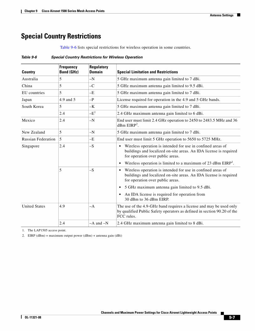
Chapter 9 Cisco Aironet 1500 Series Mesh Access Points Antenna Settings
Special Country RestrictionsTable 9-6 lists special restrictions for wireless operation in some countries.
Table 9-6 Special Country Restrictions for Wireless Operation
CountryFrequency Band (GHz)
Regulatory Domain Special Limitation and Restrictions
Australia 5 –N 5 GHz maximum antenna gain limited to 7 dBi.
China 5 –C 5 GHz maximum antenna gain limited to 9.5 dBi.
EU countries 5 –E 5 GHz maximum antenna gain limited to 7 dBi.
Japan 4.9 and 5 –P License required for operation in the 4.9 and 5 GHz bands.
South Korea 5 –K 5 GHz maximum antenna gain limited to 7 dBi.
2.4 –E1
1. The LAP1505 access point.
2.4 GHz maximum antenna gain limited to 6 dBi.
Mexico 2.4 –N End user must limit 2.4 GHz operation to 2450 to 2483.5 MHz and 36 dBm EIRP2.
2. EIRP (dBm) = maximum output power (dBm) + antenna gain (dBi)
New Zealand 5 –N 5 GHz maximum antenna gain limited to 7 dBi.
Russian Federation 5 –E End user must limit 5 GHz operation to 5650 to 5725 MHz.
Singapore 2.4 –S • Wireless operation is intended for use in confined areas of buildings and localized on-site areas. An IDA license is required for operation over public areas.
• Wireless operation is limited to a maximum of 23 dBm EIRP1.
5 –S • Wireless operation is intended for use in confined areas of buildings and localized on-site areas. An IDA license is required for operation over public areas.
• 5 GHz maximum antenna gain limited to 9.5 dBi.
• An IDA license is required for operation from 30 dBm to 36 dBm EIRP.
United States 4.9 –A The use of the 4.9-GHz band requires a license and may be used only by qualified Public Safety operators as defined in section 90.20 of the FCC rules.
2.4 –A and –N 2.4 GHz maximum antenna gain limited to 8 dBi.
9-7Channels and Maximum Power Settings for Cisco Aironet Lightweight Access Points
OL-11321-08
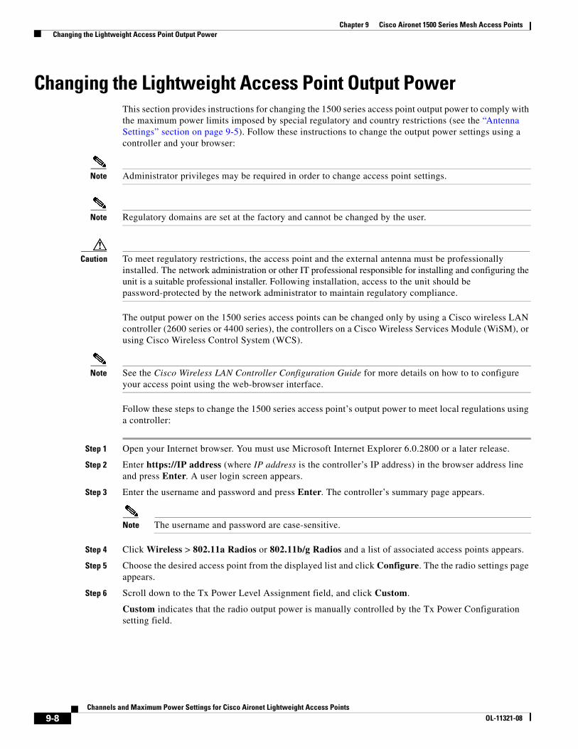
Chapter 9 Cisco Aironet 1500 Series Mesh Access Points Changing the Lightweight Access Point Output Power
Changing the Lightweight Access Point Output PowerThis section provides instructions for changing the 1500 series access point output power to comply with the maximum power limits imposed by special regulatory and country restrictions (see the “Antenna Settings” section on page 9-5). Follow these instructions to change the output power settings using a controller and your browser:
Note Administrator privileges may be required in order to change access point settings.
Note Regulatory domains are set at the factory and cannot be changed by the user.
Caution To meet regulatory restrictions, the access point and the external antenna must be professionally installed. The network administration or other IT professional responsible for installing and configuring the unit is a suitable professional installer. Following installation, access to the unit should be password-protected by the network administrator to maintain regulatory compliance.
The output power on the 1500 series access points can be changed only by using a Cisco wireless LAN controller (2600 series or 4400 series), the controllers on a Cisco Wireless Services Module (WiSM), or using Cisco Wireless Control System (WCS).
Note See the Cisco Wireless LAN Controller Configuration Guide for more details on how to to configure your access point using the web-browser interface.
Follow these steps to change the 1500 series access point’s output power to meet local regulations using a controller:
Step 1 Open your Internet browser. You must use Microsoft Internet Explorer 6.0.2800 or a later release.
Step 2 Enter https://IP address (where IP address is the controller’s IP address) in the browser address line and press Enter. A user login screen appears.
Step 3 Enter the username and password and press Enter. The controller’s summary page appears.
Note The username and password are case-sensitive.
Step 4 Click Wireless > 802.11a Radios or 802.11b/g Radios and a list of associated access points appears.
Step 5 Choose the desired access point from the displayed list and click Configure. The the radio settings page appears.
Step 6 Scroll down to the Tx Power Level Assignment field, and click Custom.
Custom indicates that the radio output power is manually controlled by the Tx Power Configuration setting field.
9-8Channels and Maximum Power Settings for Cisco Aironet Lightweight Access Points
OL-11321-08
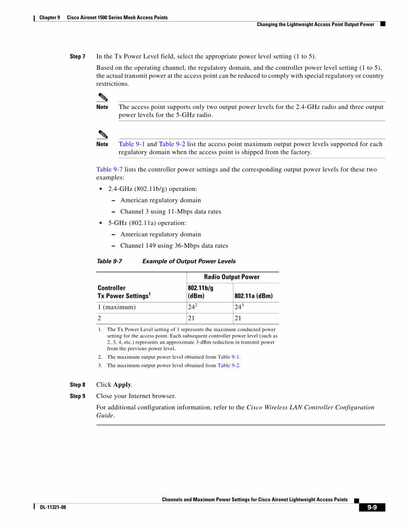
Chapter 9 Cisco Aironet 1500 Series Mesh Access Points Changing the Lightweight Access Point Output Power
Step 7 In the Tx Power Level field, select the appropriate power level setting (1 to 5).
Based on the operating channel, the regulatory domain, and the controller power level setting (1 to 5), the actual transmit power at the access point can be reduced to comply with special regulatory or country restrictions.
Note The access point supports only two output power levels for the 2.4-GHz radio and three output power levels for the 5-GHz radio.
Note Table 9-1 and Table 9-2 list the access point maximum output power levels supported for each regulatory domain when the access point is shipped from the factory.
Table 9-7 lists the controller power settings and the corresponding output power levels for these two examples:
• 2.4-GHz (802.11b/g) operation:
– American regulatory domain
– Channel 3 using 11-Mbps data rates
• 5-GHz (802.11a) operation:
– American regulatory domain
– Channel 149 using 36-Mbps data rates
Step 8 Click Apply.
Step 9 Close your Internet browser.
For additional configuration information, refer to the Cisco Wireless LAN Controller Configuration Guide.
Table 9-7 Example of Output Power Levels
Controller Tx Power Settings1
1. The Tx Power Level setting of 1 represents the maximum conducted power setting for the access point. Each subsequent controller power level (such as 2, 3, 4, etc.) represents an approximate 3-dBm reduction in transmit power from the previous power level.
Radio Output Power
802.11b/g (dBm) 802.11a (dBm)
1 (maximum) 242
2. The maximum output power level obtained from Table 9-1.
243
3. The maximum output power level obtained from Table 9-2.
2 21 21
9-9Channels and Maximum Power Settings for Cisco Aironet Lightweight Access Points
OL-11321-08
Chapter 9 Cisco Aironet 1500 Series Mesh Access Points Changing the Lightweight Access Point Output Power
9-10Channels and Maximum Power Settings for Cisco Aironet Lightweight Access Points
OL-11321-08
Channels and Maximum Power SeOL-11321-08
C H A P T E R 10
Cisco Aironet 1520 Series Mesh Access PointsThis chapter lists the 1520 series mesh access point IEEE 802.11b/g (2.4-GHz) and IEEE 802.11a (5-GHz) channels and the maximum power levels supported by the world’s regulatory domains. For additional product hardware information refer to the Cisco Aironet 1520 Series Outdoor Mesh Access Point Hardware Installation Guide.
The AIR-LAP1522 access point model supports both 802.11b/g and 802.11a radios. The AIR-LAP1521 access point model only supports a 802.11b/g radio.
The following topics are covered in this chapter:
• Channels and Maximum Power Levels, page 10-2
• Changing the Lightweight Access Point Output Power, page 10-14
10-1ttings for Cisco Aironet Lightweight Access Points
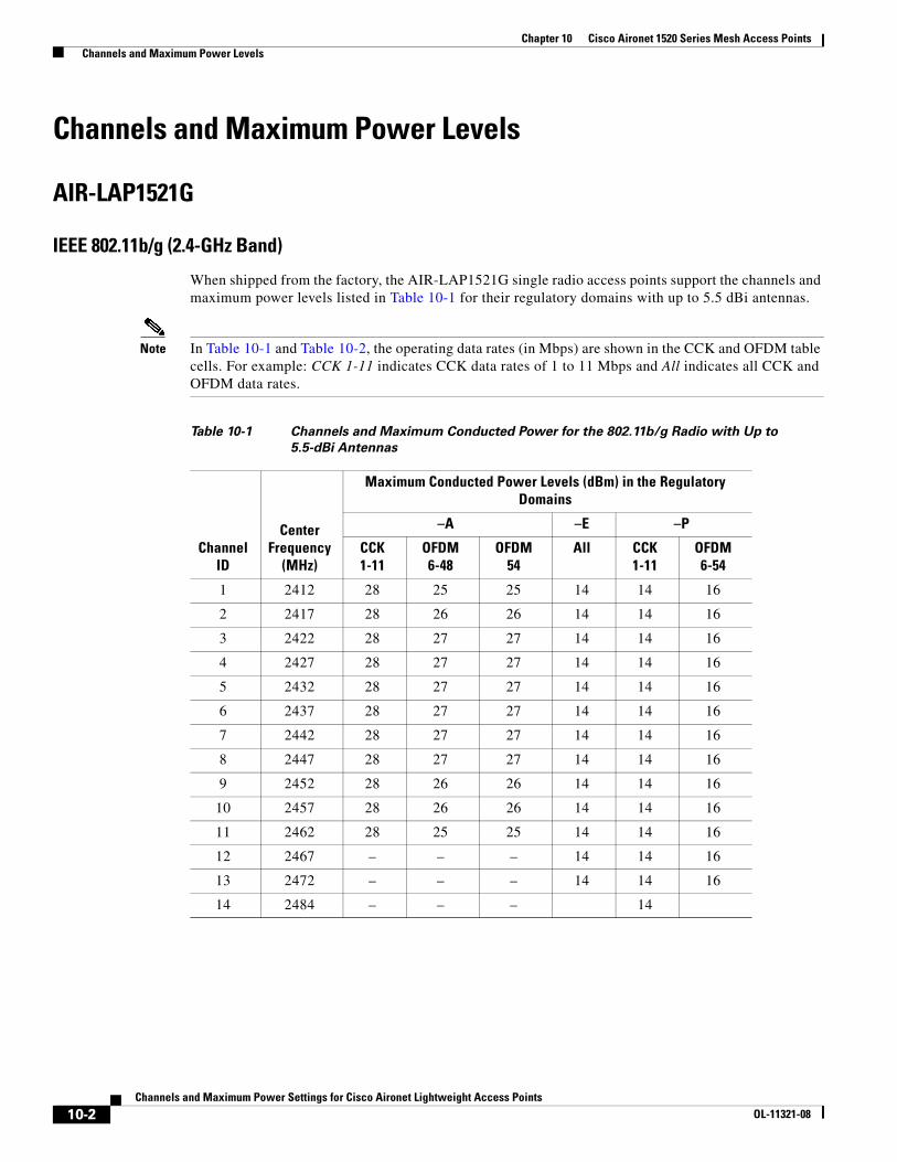
Chapter 10 Cisco Aironet 1520 Series Mesh Access Points Channels and Maximum Power Levels
Channels and Maximum Power Levels
AIR-LAP1521G
IEEE 802.11b/g (2.4-GHz Band)
When shipped from the factory, the AIR-LAP1521G single radio access points support the channels and maximum power levels listed in Table 10-1 for their regulatory domains with up to 5.5 dBi antennas.
Note In Table 10-1 and Table 10-2, the operating data rates (in Mbps) are shown in the CCK and OFDM table cells. For example: CCK 1-11 indicates CCK data rates of 1 to 11 Mbps and All indicates all CCK and OFDM data rates.
Table 10-1 Channels and Maximum Conducted Power for the 802.11b/g Radio with Up to
5.5-dBi Antennas
Channel ID
Center Frequency
(MHz)
Maximum Conducted Power Levels (dBm) in the Regulatory Domains
–A –E –P
CCK1-11
OFDM6-48
OFDM54
All CCK1-11
OFDM6-54
1 2412 28 25 25 14 14 16
2 2417 28 26 26 14 14 16
3 2422 28 27 27 14 14 16
4 2427 28 27 27 14 14 16
5 2432 28 27 27 14 14 16
6 2437 28 27 27 14 14 16
7 2442 28 27 27 14 14 16
8 2447 28 27 27 14 14 16
9 2452 28 26 26 14 14 16
10 2457 28 26 26 14 14 16
11 2462 28 25 25 14 14 16
12 2467 – – – 14 14 16
13 2472 – – – 14 14 16
14 2484 – – – 14
10-2Channels and Maximum Power Settings for Cisco Aironet Lightweight Access Points
OL-11321-08
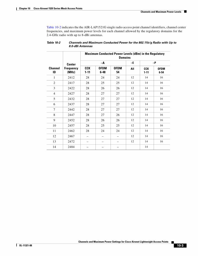
Chapter 10 Cisco Aironet 1520 Series Mesh Access Points Channels and Maximum Power Levels
Table 10-2 indicates the the AIR-LAP1521G single radio access point channel identifiers, channel center frequencies, and maximum power levels for each channel allowed by the regulatory domains for the 2.4-GHz radio with up to 8-dBi antennas.
Table 10-2 Channels and Maximum Conducted Power for the 802.11b/g Radio with Up to
8.0-dBi Antennas
Channel ID
Center Frequency
(MHz)
Maximum Conducted Power Levels (dBm) in the Regulatory Domains
–A –E –P
CCK1-11
OFDM6-48
OFDM54
All CCK1-11
OFDM6-54
1 2412 28 24 24 12 14 16
2 2417 28 25 25 12 14 16
3 2422 28 26 26 12 14 16
4 2427 28 27 27 12 14 16
5 2432 28 27 27 12 14 16
6 2437 28 27 27 12 14 16
7 2442 28 27 27 12 14 16
8 2447 28 27 26 12 14 16
9 2452 28 26 26 12 14 16
10 2457 28 25 25 12 14 16
11 2462 28 24 24 12 14 16
12 2467 – – – 12 14 16
13 2472 – – – 12 14 16
14 2484 – – – 14
10-3Channels and Maximum Power Settings for Cisco Aironet Lightweight Access Points
OL-11321-08
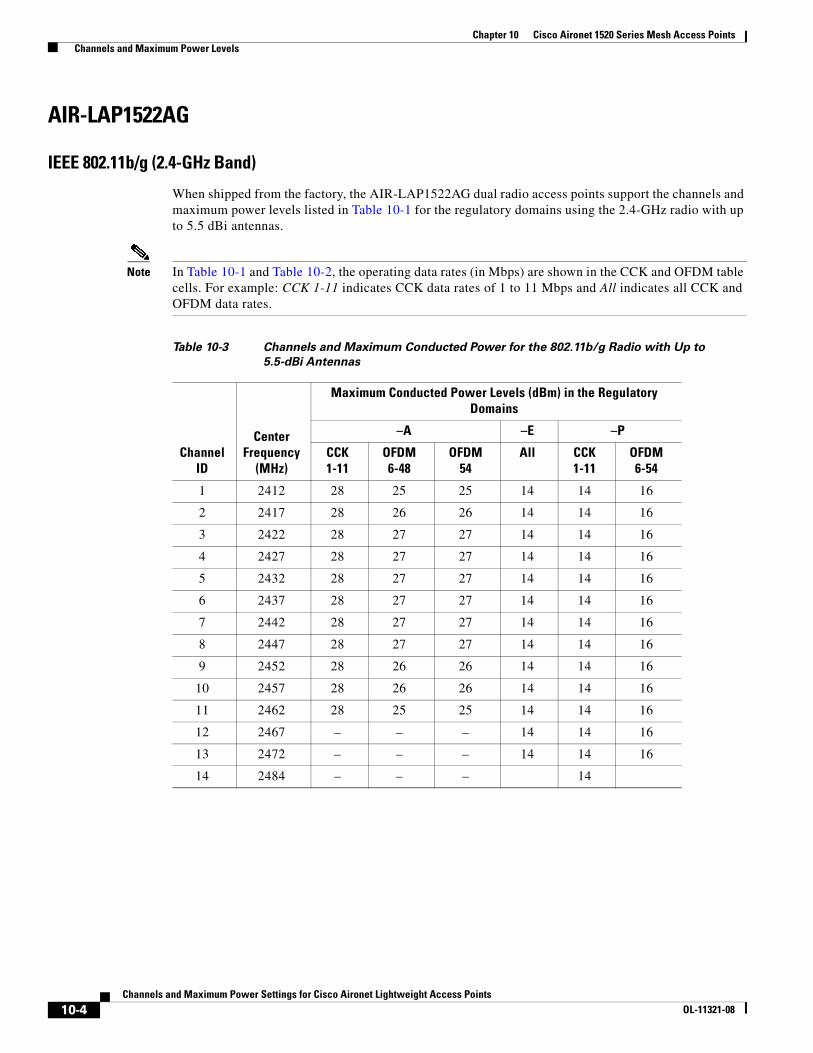
Chapter 10 Cisco Aironet 1520 Series Mesh Access Points Channels and Maximum Power Levels
AIR-LAP1522AG
IEEE 802.11b/g (2.4-GHz Band)
When shipped from the factory, the AIR-LAP1522AG dual radio access points support the channels and maximum power levels listed in Table 10-1 for the regulatory domains using the 2.4-GHz radio with up to 5.5 dBi antennas.
Note In Table 10-1 and Table 10-2, the operating data rates (in Mbps) are shown in the CCK and OFDM table cells. For example: CCK 1-11 indicates CCK data rates of 1 to 11 Mbps and All indicates all CCK and OFDM data rates.
Table 10-3 Channels and Maximum Conducted Power for the 802.11b/g Radio with Up to
5.5-dBi Antennas
Channel ID
Center Frequency
(MHz)
Maximum Conducted Power Levels (dBm) in the Regulatory Domains
–A –E –P
CCK1-11
OFDM6-48
OFDM54
All CCK1-11
OFDM6-54
1 2412 28 25 25 14 14 16
2 2417 28 26 26 14 14 16
3 2422 28 27 27 14 14 16
4 2427 28 27 27 14 14 16
5 2432 28 27 27 14 14 16
6 2437 28 27 27 14 14 16
7 2442 28 27 27 14 14 16
8 2447 28 27 27 14 14 16
9 2452 28 26 26 14 14 16
10 2457 28 26 26 14 14 16
11 2462 28 25 25 14 14 16
12 2467 – – – 14 14 16
13 2472 – – – 14 14 16
14 2484 – – – 14
10-4Channels and Maximum Power Settings for Cisco Aironet Lightweight Access Points
OL-11321-08
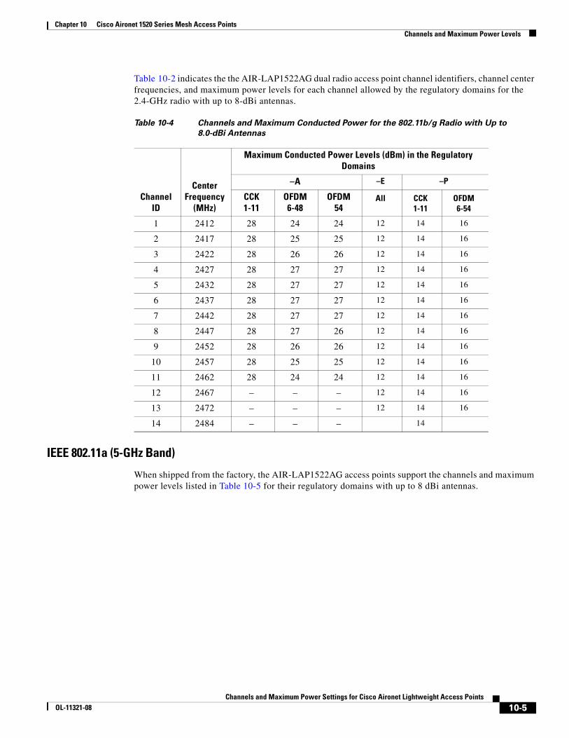
Chapter 10 Cisco Aironet 1520 Series Mesh Access Points Channels and Maximum Power Levels
Table 10-2 indicates the the AIR-LAP1522AG dual radio access point channel identifiers, channel center frequencies, and maximum power levels for each channel allowed by the regulatory domains for the 2.4-GHz radio with up to 8-dBi antennas.
IEEE 802.11a (5-GHz Band)
When shipped from the factory, the AIR-LAP1522AG access points support the channels and maximum power levels listed in Table 10-5 for their regulatory domains with up to 8 dBi antennas.
Table 10-4 Channels and Maximum Conducted Power for the 802.11b/g Radio with Up to
8.0-dBi Antennas
Channel ID
Center Frequency
(MHz)
Maximum Conducted Power Levels (dBm) in the Regulatory Domains
–A –E –P
CCK1-11
OFDM6-48
OFDM54
All CCK1-11
OFDM6-54
1 2412 28 24 24 12 14 16
2 2417 28 25 25 12 14 16
3 2422 28 26 26 12 14 16
4 2427 28 27 27 12 14 16
5 2432 28 27 27 12 14 16
6 2437 28 27 27 12 14 16
7 2442 28 27 27 12 14 16
8 2447 28 27 26 12 14 16
9 2452 28 26 26 12 14 16
10 2457 28 25 25 12 14 16
11 2462 28 24 24 12 14 16
12 2467 – – – 12 14 16
13 2472 – – – 12 14 16
14 2484 – – – 14
10-5Channels and Maximum Power Settings for Cisco Aironet Lightweight Access Points
OL-11321-08
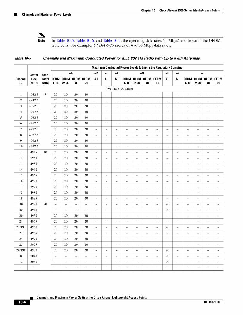
Chapter 10 Cisco Aironet 1520 Series Mesh Access Points Channels and Maximum Power Levels
Note In Table 10-5, Table 10-6, and Table 10-7, the operating data rates (in Mbps) are shown in the OFDM table cells. For example: OFDM 6-36 indicates 6 to 36 Mbps data rates.
Table 10-5 Channels and Maximum Conducted Power for IEEE 802.11a Radio with Up to 8 dBi Antennas
ChannelID
Center Freq
(MHz)
Band-width(MHz)
Maximum Conducted Power Levels (dBm) in the Regulatory Domains
–A –C –E –K –N –P –S –T
OFDM6-18
OFDM24-36
OFDM48
OFDM54
All All All OFDM6-18
OFDM24-36
OFDM48
OFDM54
All All OFDM6-18
OFDM24-36
OFDM48
OFDM54
(4900 to 5100 MHz)
1 4942.5 5 20 20 20 20 – – – – – – – – – – – – –
2 4947.5 20 20 20 20 – – – – – – – – – – – – –
3 4952.5 20 20 20 20 – – – – – – – – – – – – –
4 4957.5 20 20 20 20 – – – – – – – – – – – – –
5 4962.5 20 20 20 20 – – – – – – – – – – – – –
6 4967.5 20 20 20 20 – – – – – – – – – – – – –
7 4972.5 20 20 20 20 – – – – – – – – – – – – –
8 4977.5 20 20 20 20 – – – – – – – – – – – – –
9 4982.5 20 20 20 20 – – – – – – – – – – – – –
10 4987.5 20 20 20 20 – – – – – – – – – – – – –
11 4945 10 20 20 20 20 – – – – – – – – – – – – –
12 5950 20 20 20 20 – – – – – – – – – – – – –
13 4955 20 20 20 20 – – – – – – – – – – – – –
14 4960 20 20 20 20 – – – – – – – – – – – – –
15 4965 20 20 20 20 – – – – – – – – – – – – –
16 4970 20 20 20 20 – – – – – – – – – – – – –
17 5975 20 20 20 20 – – – – – – – – – – – – –
18 4980 20 20 20 20 – – – – – – – – – – – – –
19 4985 20 20 20 20 – – – – – – – – – – – – –
184 4920 20 – – – – – – – – – – – 20 – – – – –
188 4940 – – – – – – – – – – – 20 – – – – –
20 4950 20 20 20 20 – – – – – – – – – – – – –
21 4955 20 20 20 20 – – – – – – – – – – – – –
22/192 4960 20 20 20 20 – – – – – – – 20 – – – – –
23 4965 20 20 20 20 – – – – – – – – – – – – –
24 4970 20 20 20 20 – – – – – – – – – – – – –
25 5975 20 20 20 20 – – – – – – – – – – – – –
26/196 4980 20 20 20 20 – – – – – – – 20 – – – – –
8 5040 – – – – – – – – – – – 20 – – – – –
12 5060 – – – – – – – – – – – 20 – – – – –
– – – – – – – – – – – – – – – – – – –
10-6Channels and Maximum Power Settings for Cisco Aironet Lightweight Access Points
OL-11321-08
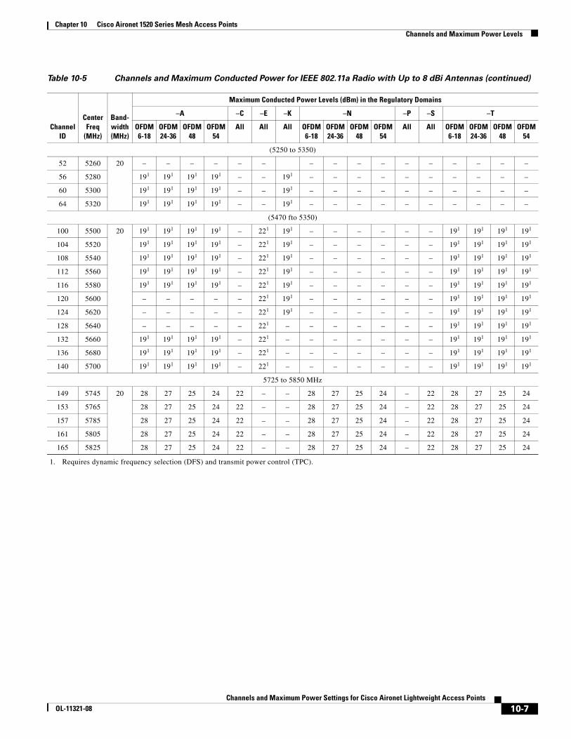
Chapter 10 Cisco Aironet 1520 Series Mesh Access Points Channels and Maximum Power Levels
(5250 to 5350)
52 5260 20 – – – – – – – – – – – – – – – –
56 5280 191 191 191 191 – – 191 – – – – – – – – – –
60 5300 191 191 191 191 – – 191 – – – – – – – – – –
64 5320 191 191 191 191 – – 191 – – – – – – – – – –
(5470 fto 5350)
100 5500 20 191 191 191 191 – 221 191 – – – – – – 191 191 191 191
104 5520 191 191 191 191 – 221 191 – – – – – – 191 191 191 191
108 5540 191 191 191 191 – 221 191 – – – – – – 191 191 191 191
112 5560 191 191 191 191 – 221 191 – – – – – – 191 191 191 191
116 5580 191 191 191 191 – 221 191 – – – – – – 191 191 191 191
120 5600 – – – – – 221 191 – – – – – – 191 191 191 191
124 5620 – – – – – 221 191 – – – – – – 191 191 191 191
128 5640 – – – – – 221 – – – – – – – 191 191 191 191
132 5660 191 191 191 191 – 221 – – – – – – – 191 191 191 191
136 5680 191 191 191 191 – 221 – – – – – – – 191 191 191 191
140 5700 191 191 191 191 – 221 – – – – – – – 191 191 191 191
5725 to 5850 MHz
149 5745 20 28 27 25 24 22 – – 28 27 25 24 – 22 28 27 25 24
153 5765 28 27 25 24 22 – – 28 27 25 24 – 22 28 27 25 24
157 5785 28 27 25 24 22 – – 28 27 25 24 – 22 28 27 25 24
161 5805 28 27 25 24 22 – – 28 27 25 24 – 22 28 27 25 24
165 5825 28 27 25 24 22 – – 28 27 25 24 – 22 28 27 25 24
1. Requires dynamic frequency selection (DFS) and transmit power control (TPC).
Table 10-5 Channels and Maximum Conducted Power for IEEE 802.11a Radio with Up to 8 dBi Antennas (continued)
ChannelID
Center Freq
(MHz)
Band-width(MHz)
Maximum Conducted Power Levels (dBm) in the Regulatory Domains
–A –C –E –K –N –P –S –T
OFDM6-18
OFDM24-36
OFDM48
OFDM54
All All All OFDM6-18
OFDM24-36
OFDM48
OFDM54
All All OFDM6-18
OFDM24-36
OFDM48
OFDM54
10-7Channels and Maximum Power Settings for Cisco Aironet Lightweight Access Points
OL-11321-08
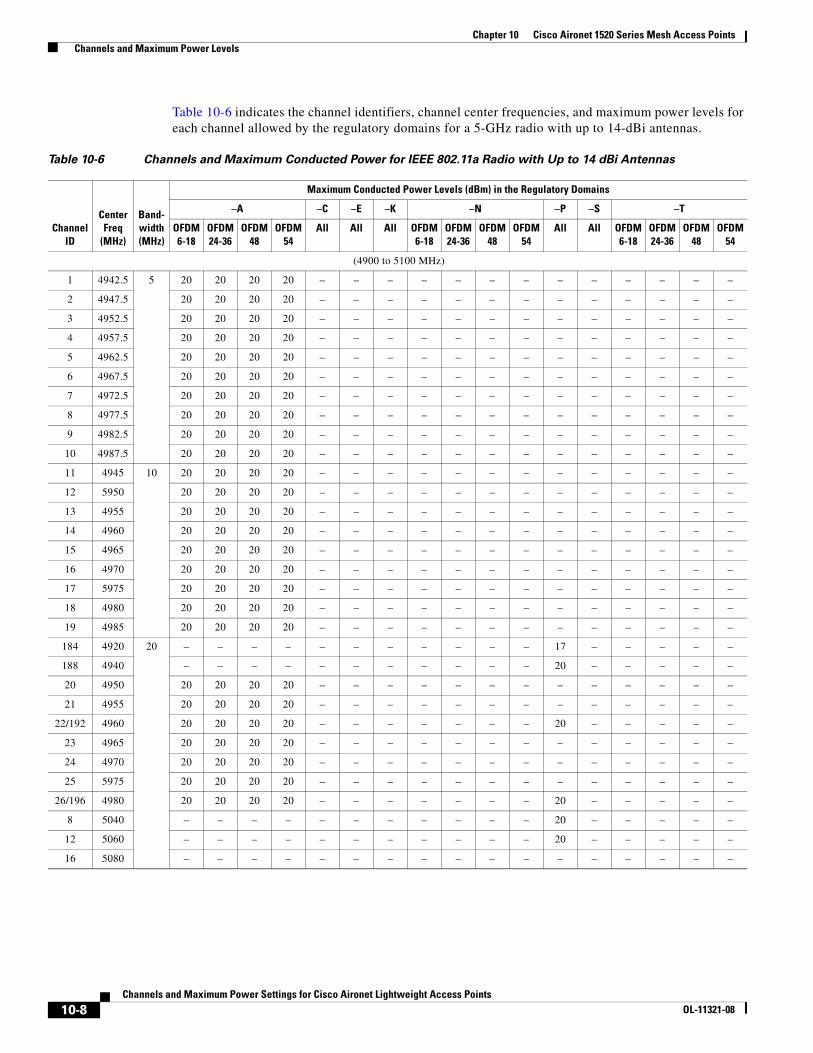
Chapter 10 Cisco Aironet 1520 Series Mesh Access Points Channels and Maximum Power Levels
Table 10-6 indicates the channel identifiers, channel center frequencies, and maximum power levels for each channel allowed by the regulatory domains for a 5-GHz radio with up to 14-dBi antennas.
Table 10-6 Channels and Maximum Conducted Power for IEEE 802.11a Radio with Up to 14 dBi Antennas
ChannelID
Center Freq
(MHz)
Band-width(MHz)
Maximum Conducted Power Levels (dBm) in the Regulatory Domains
–A –C –E –K –N –P –S –T
OFDM6-18
OFDM24-36
OFDM48
OFDM54
All All All OFDM6-18
OFDM24-36
OFDM48
OFDM54
All All OFDM6-18
OFDM24-36
OFDM48
OFDM54
(4900 to 5100 MHz)
1 4942.5 5 20 20 20 20 – – – – – – – – – – – – –
2 4947.5 20 20 20 20 – – – – – – – – – – – – –
3 4952.5 20 20 20 20 – – – – – – – – – – – – –
4 4957.5 20 20 20 20 – – – – – – – – – – – – –
5 4962.5 20 20 20 20 – – – – – – – – – – – – –
6 4967.5 20 20 20 20 – – – – – – – – – – – – –
7 4972.5 20 20 20 20 – – – – – – – – – – – – –
8 4977.5 20 20 20 20 – – – – – – – – – – – – –
9 4982.5 20 20 20 20 – – – – – – – – – – – – –
10 4987.5 20 20 20 20 – – – – – – – – – – – – –
11 4945 10 20 20 20 20 – – – – – – – – – – – – –
12 5950 20 20 20 20 – – – – – – – – – – – – –
13 4955 20 20 20 20 – – – – – – – – – – – – –
14 4960 20 20 20 20 – – – – – – – – – – – – –
15 4965 20 20 20 20 – – – – – – – – – – – – –
16 4970 20 20 20 20 – – – – – – – – – – – – –
17 5975 20 20 20 20 – – – – – – – – – – – – –
18 4980 20 20 20 20 – – – – – – – – – – – – –
19 4985 20 20 20 20 – – – – – – – – – – – – –
184 4920 20 – – – – – – – – – – – 17 – – – – –
188 4940 – – – – – – – – – – – 20 – – – – –
20 4950 20 20 20 20 – – – – – – – – – – – – –
21 4955 20 20 20 20 – – – – – – – – – – – – –
22/192 4960 20 20 20 20 – – – – – – – 20 – – – – –
23 4965 20 20 20 20 – – – – – – – – – – – – –
24 4970 20 20 20 20 – – – – – – – – – – – – –
25 5975 20 20 20 20 – – – – – – – – – – – – –
26/196 4980 20 20 20 20 – – – – – – – 20 – – – – –
8 5040 – – – – – – – – – – – 20 – – – – –
12 5060 – – – – – – – – – – – 20 – – – – –
16 5080 – – – – – – – – – – – – – – – – –
10-8Channels and Maximum Power Settings for Cisco Aironet Lightweight Access Points
OL-11321-08
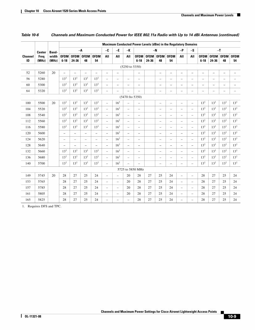
Chapter 10 Cisco Aironet 1520 Series Mesh Access Points Channels and Maximum Power Levels
(5250 to 5350)
52 5260 20 – – – – – – – – – – – – – – –
56 5280 131 131 131 131 – – – – – – – – – – – –
60 5300 131 131 131 131 – – – – – – – – – – – –
64 5320 131 131 131 131 – – – – – – – – – – – –
(5470 fto 5350)
100 5500 20 131 131 131 131 – 161 – – – – – – 131 131 131 131
104 5520 131 131 131 131 – 161 – – – – – – 131 131 131 131
108 5540 131 131 131 131 – 161 – – – – – – 131 131 131 131
112 5560 131 131 131 131 – 161 – – – – – – 131 131 131 131
116 5580 131 131 131 131 – 161 – – – – – – 131 131 131 131
120 5600 – – – – – 161 – – – – – – 131 131 131 131
124 5620 – – – – – 161 – – – – – – 131 131 131 131
128 5640 – – – – – 161 – – – – – – 131 131 131 131
132 5660 131 131 131 131 – 161 – – – – – – 131 131 131 131
136 5680 131 131 131 131 – 161 – – – – – – 131 131 131 131
140 5700 131 131 131 131 – 161 – – – – – – 131 131 131 131
5725 to 5850 MHz
149 5745 20 28 27 25 24 – – 20 28 27 25 24 – – 28 27 25 24
153 5765 28 27 25 24 – – 20 28 27 25 24 – – 28 27 25 24
157 5785 28 27 25 24 – – 20 28 27 25 24 – – 28 27 25 24
161 5805 28 27 25 24 – – 20 28 27 25 24 – – 28 27 25 24
165 5825 28 27 25 24 – – – 28 27 25 24 – – 28 27 25 24
1. Requires DFS and TPC.
Table 10-6 Channels and Maximum Conducted Power for IEEE 802.11a Radio with Up to 14 dBi Antennas (continued)
ChannelID
Center Freq
(MHz)
Band-width(MHz)
Maximum Conducted Power Levels (dBm) in the Regulatory Domains
–A –C –E –K –N –P –S –T
OFDM6-18
OFDM24-36
OFDM48
OFDM54
All All All OFDM6-18
OFDM24-36
OFDM48
OFDM54
All All OFDM6-18
OFDM24-36
OFDM48
OFDM54
10-9Channels and Maximum Power Settings for Cisco Aironet Lightweight Access Points
OL-11321-08
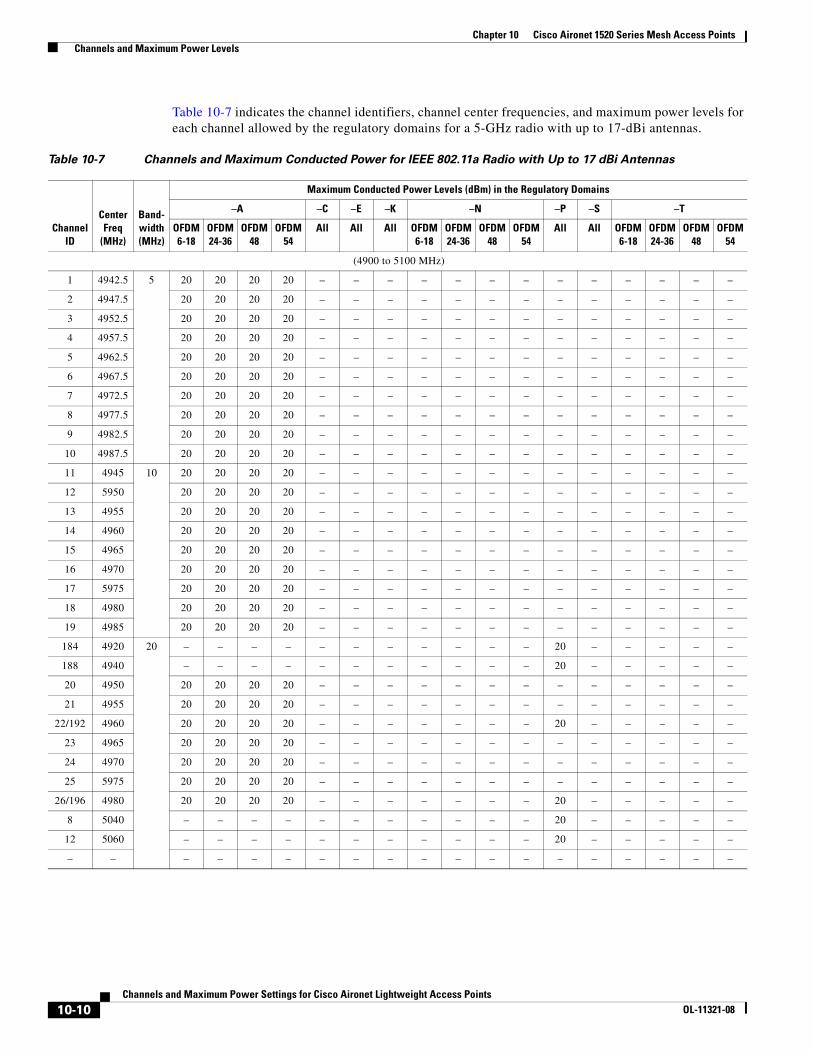
Chapter 10 Cisco Aironet 1520 Series Mesh Access Points Channels and Maximum Power Levels
Table 10-7 indicates the channel identifiers, channel center frequencies, and maximum power levels for each channel allowed by the regulatory domains for a 5-GHz radio with up to 17-dBi antennas.
Table 10-7 Channels and Maximum Conducted Power for IEEE 802.11a Radio with Up to 17 dBi Antennas
ChannelID
Center Freq
(MHz)
Band-width(MHz)
Maximum Conducted Power Levels (dBm) in the Regulatory Domains
–A –C –E –K –N –P –S –T
OFDM6-18
OFDM24-36
OFDM48
OFDM54
All All All OFDM6-18
OFDM24-36
OFDM48
OFDM54
All All OFDM6-18
OFDM24-36
OFDM48
OFDM54
(4900 to 5100 MHz)
1 4942.5 5 20 20 20 20 – – – – – – – – – – – – –
2 4947.5 20 20 20 20 – – – – – – – – – – – – –
3 4952.5 20 20 20 20 – – – – – – – – – – – – –
4 4957.5 20 20 20 20 – – – – – – – – – – – – –
5 4962.5 20 20 20 20 – – – – – – – – – – – – –
6 4967.5 20 20 20 20 – – – – – – – – – – – – –
7 4972.5 20 20 20 20 – – – – – – – – – – – – –
8 4977.5 20 20 20 20 – – – – – – – – – – – – –
9 4982.5 20 20 20 20 – – – – – – – – – – – – –
10 4987.5 20 20 20 20 – – – – – – – – – – – – –
11 4945 10 20 20 20 20 – – – – – – – – – – – – –
12 5950 20 20 20 20 – – – – – – – – – – – – –
13 4955 20 20 20 20 – – – – – – – – – – – – –
14 4960 20 20 20 20 – – – – – – – – – – – – –
15 4965 20 20 20 20 – – – – – – – – – – – – –
16 4970 20 20 20 20 – – – – – – – – – – – – –
17 5975 20 20 20 20 – – – – – – – – – – – – –
18 4980 20 20 20 20 – – – – – – – – – – – – –
19 4985 20 20 20 20 – – – – – – – – – – – – –
184 4920 20 – – – – – – – – – – – 20 – – – – –
188 4940 – – – – – – – – – – – 20 – – – – –
20 4950 20 20 20 20 – – – – – – – – – – – – –
21 4955 20 20 20 20 – – – – – – – – – – – – –
22/192 4960 20 20 20 20 – – – – – – – 20 – – – – –
23 4965 20 20 20 20 – – – – – – – – – – – – –
24 4970 20 20 20 20 – – – – – – – – – – – – –
25 5975 20 20 20 20 – – – – – – – – – – – – –
26/196 4980 20 20 20 20 – – – – – – – 20 – – – – –
8 5040 – – – – – – – – – – – 20 – – – – –
12 5060 – – – – – – – – – – – 20 – – – – –
– – – – – – – – – – – – – – – – – – –
10-10Channels and Maximum Power Settings for Cisco Aironet Lightweight Access Points
OL-11321-08
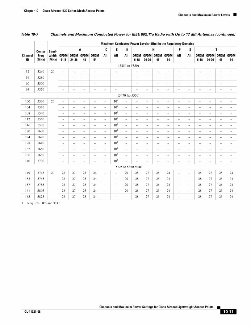
Chapter 10 Cisco Aironet 1520 Series Mesh Access Points Channels and Maximum Power Levels
(5250 to 5350)
52 5260 20 – – – – – – – – – – – – – – – –
56 5280 – – – – – – – – – – – – – – – –
60 5300 – – – – – – – – – – – – – – – –
64 5320 – – – – – – – – – – – – – – – –
(5470 fto 5350)
100 5500 20 – – – – – 101 – – – – – – – – – – –
104 5520 – – – – – 101 – – – – – – – – – – –
108 5540 – – – – – 101 – – – – – – – – – – –
112 5560 – – – – – 101 – – – – – – – – – – –
116 5580 – – – – – 101 – – – – – – – – – – –
120 5600 – – – – – 101 – – – – – – – – – – –
124 5620 – – – – – 101 – – – – – – – – – – –
128 5640 – – – – – 101 – – – – – – – – – – –
132 5660 – – – – – 101 – – – – – – – – – – –
136 5680 – – – – – 101 – – – – – – – – – – –
140 5700 – – – – – 101 – – – – – – – – – – –
5725 to 5850 MHz
149 5745 20 28 27 25 24 – – 20 28 27 25 24 – – 28 27 25 24
153 5765 28 27 25 24 – – 20 28 27 25 24 – – 28 27 25 24
157 5785 28 27 25 24 – – 20 28 27 25 24 – – 28 27 25 24
161 5805 28 27 25 24 – – 20 28 27 25 24 – – 28 27 25 24
165 5825 28 27 25 24 – – – 28 27 25 24 – – 28 27 25 24
1. Requires DFS and TPC.
Table 10-7 Channels and Maximum Conducted Power for IEEE 802.11a Radio with Up to 17 dBi Antennas (continued)
ChannelID
Center Freq
(MHz)
Band-width(MHz)
Maximum Conducted Power Levels (dBm) in the Regulatory Domains
–A –C –E –K –N –P –S –T
OFDM6-18
OFDM24-36
OFDM48
OFDM54
All All All OFDM6-18
OFDM24-36
OFDM48
OFDM54
All All OFDM6-18
OFDM24-36
OFDM48
OFDM54
10-11Channels and Maximum Power Settings for Cisco Aironet Lightweight Access Points
OL-11321-08

Chapter 10 Cisco Aironet 1520 Series Mesh Access Points Channels and Maximum Power Levels
Minimum 5-GHz Radio Power LevelsTable 10-8 lists the minimum power levels supported by the 5-GHz radio for the various channels and regulatory domains.
Note When the minimum radio power level is reached with a controller power setting (1 to 5), changing the controller power setting to a lower value does not result in a lower radio output power level. For example, if the minimum radio power level corresponds to controller level 3, then levels 4 and 5 also correspond to the same power level.
Table 10-8 5-GHz Radio Minimum Power Levels
ChannelID
Center Freq
(MHz)
Band-width(MHz)
Minimum Radio Power Levels (dBm) in the Regulatory Domains
–A –C –E –K –N –P –S –T
OFDM6-18
OFDM24-36
OFDM48
OFDM54
All All All OFDM6-18
OFDM24-36
OFDM48
OFDM54
All All OFDM6-18
OFDM24-36
OFDM48
OFDM54
(4900 to 5100 MHz)
1 4942.5 5 8 8 8 8 – – – – – – – – – – – – –
2 4947.5 8 8 8 8 – – – – – – – – – – – – –
3 4952.5 8 8 8 8 – – – – – – – – – – – – –
4 4957.5 8 8 8 8 – – – – – – – – – – – – –
5 4962.5 8 8 8 8 – – – – – – – – – – – – –
6 4967.5 8 8 8 8 – – – – – – – – – – – – –
7 4972.5 8 8 8 8 – – – – – – – – – – – – –
8 4977.5 8 8 8 8 – – – – – – – – – – – – –
9 4982.5 8 8 8 8 – – – – – – – – – – – – –
10 4987.5 8 8 8 8 – – – – – – – – – – – – –
11 4945 10 8 8 8 8 – – – – – – – – – – – – –
12 5950 8 8 8 8 – – – – – – – – – – – – –
13 4955 8 8 8 8 – – – – – – – – – – – – –
14 4960 8 8 8 8 – – – – – – – – – – – – –
15 4965 8 8 8 8 – – – – – – – – – – – – –
16 4970 8 8 8 8 – – – – – – – – – – – – –
17 5975 8 8 8 8 – – – – – – – – – – – – –
18 4980 8 8 8 8 – – – – – – – – – – – – –
19 4985 8 8 8 8 – – – – – – – – – – – – –
184 4920 20 – – – – – – – – – – – 8 – – – – –
188 4940 – – – – – – – – – – – 8 – – – – –
20 4950 8 8 8 8 – – – – – – – – – – – – –
21 4955 8 8 8 8 – – – – – – – – – – – – –
22/192 4960 8 8 8 8 – – – – – – – 8 – – – – –
23 4965 8 8 8 8 – – – – – – – – – – – – –
24 4970 8 8 8 8 – – – – – – – – – – – – –
25 5975 8 8 8 8 – – – – – – – – – – – – –
26/196 4980 8 8 8 8 – – – – – – – 8 – – – – –
8 5040 – – – – – – – – – – – 8 – – – – –
12 5060 – – – – – – – – – – – 8 – – – – –
16 5080 – – – – – – – – – – – – – – – – –
10-12Channels and Maximum Power Settings for Cisco Aironet Lightweight Access Points
OL-11321-08
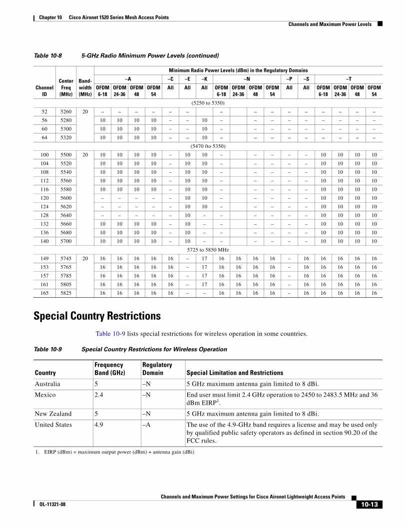
Chapter 10 Cisco Aironet 1520 Series Mesh Access Points Channels and Maximum Power Levels
Special Country RestrictionsTable 10-9 lists special restrictions for wireless operation in some countries.
(5250 to 5350)
52 5260 20 – – – – – – – – – – – – – – –
56 5280 10 10 10 10 – – 10 – – – – – – – – –
60 5300 10 10 10 10 – – 10 – – – – – – – – –
64 5320 10 10 10 10 – – 10 – – – – – – – – –
(5470 fto 5350)
100 5500 20 10 10 10 10 – 10 10 – – – – – 10 10 10 10
104 5520 10 10 10 10 – 10 10 – – – – – 10 10 10 10
108 5540 10 10 10 10 – 10 10 – – – – – 10 10 10 10
112 5560 10 10 10 10 – 10 10 – – – – – 10 10 10 10
116 5580 10 10 10 10 – 10 10 – – – – – 10 10 10 10
120 5600 – – – – – 10 10 – – – – – 10 10 10 10
124 5620 – – – – – 10 10 – – – – – 10 10 10 10
128 5640 – – – – – 10 – – – – – – 10 10 10 10
132 5660 10 10 10 10 – 10 – – – – – – 10 10 10 10
136 5680 10 10 10 10 – 10 – – – – – – 10 10 10 10
140 5700 10 10 10 10 – 10 – – – – – – 10 10 10 10
5725 to 5850 MHz
149 5745 20 16 16 16 16 16 – 17 16 16 16 16 – 16 16 16 16 16
153 5765 16 16 16 16 16 – 17 16 16 16 16 – 16 16 16 16 16
157 5785 16 16 16 16 16 – 17 16 16 16 16 – 16 16 16 16 16
161 5805 16 16 16 16 16 – 17 16 16 16 16 – 16 16 16 16 16
165 5825 16 16 16 16 16 – – 16 16 16 16 – 16 16 16 16 16
Table 10-8 5-GHz Radio Minimum Power Levels (continued)
ChannelID
Center Freq
(MHz)
Band-width(MHz)
Minimum Radio Power Levels (dBm) in the Regulatory Domains
–A –C –E –K –N –P –S –T
OFDM6-18
OFDM24-36
OFDM48
OFDM54
All All All OFDM6-18
OFDM24-36
OFDM48
OFDM54
All All OFDM6-18
OFDM24-36
OFDM48
OFDM54
Table 10-9 Special Country Restrictions for Wireless Operation
CountryFrequency Band (GHz)
Regulatory Domain Special Limitation and Restrictions
Australia 5 –N 5 GHz maximum antenna gain limited to 8 dBi.
Mexico 2.4 –N End user must limit 2.4 GHz operation to 2450 to 2483.5 MHz and 36 dBm EIRP1.
1. EIRP (dBm) = maximum output power (dBm) + antenna gain (dBi)
New Zealand 5 –N 5 GHz maximum antenna gain limited to 8 dBi.
United States 4.9 –A The use of the 4.9-GHz band requires a license and may be used only by qualified public safety operators as defined in section 90.20 of the FCC rules.
10-13Channels and Maximum Power Settings for Cisco Aironet Lightweight Access Points
OL-11321-08
Chapter 10 Cisco Aironet 1520 Series Mesh Access Points Changing the Lightweight Access Point Output Power
Changing the Lightweight Access Point Output PowerThis section provides instructions for changing the 1520 series access point output power to comply with the maximum power limits imposed by special regulatory and country restrictions (see the “Minimum 5-GHz Radio Power Levels” section on page 10-12). Follow these instructions to change the output power settings using a controller and your browser:
Note Administrator privileges may be required in order to change access point settings.
Caution To meet regulatory restrictions, the access point and the external antenna must be professionally installed. The network administration or other IT professional responsible for installing and configuring the unit is a suitable professional installer. Following installation, access to the unit should be password-protected by the network administrator to maintain regulatory compliance.
The output power on the 1520 series access points can be changed only by using a Cisco wireless LAN controller (2600 series or 4400 series), the controllers on a Cisco Wireless Services Module (WiSM), or using Cisco Wireless Control System (WCS).
Note See the Cisco Wireless LAN Controller Configuration Guide for more details on how to to configure your access point using the web-browser interface.
Follow these steps to change the 1520 series access point’s output power to meet local regulations using a controller:
Step 1 Open your Internet browser. You must use Microsoft Internet Explorer 6.0.2800 or a later release.
Step 2 Enter https://IP address (where IP address is the controller’s IP address) in the browser address line and press Enter. A user login screen appears.
Step 3 Enter the username and password and press Enter. The controller’s summary page appears.
Note The username and password are case-sensitive.
Step 4 Click Wireless and choose 802.11a/n or 802.11b/g/n under Access Points / Radios . A list of associated access points appears.
Step 5 Choose the desired access point from the displayed list and click Configure from the drop down arrow. The the radio configuration page appears.
Step 6 Scroll to the Tx Power Level Assignment field, and click Custom.
Custom indicates that the radio output power is manually controlled by the Tx Power Configuration setting field.
Step 7 In the Tx Power Level field, select the appropriate power level setting (1 to 5).
Based on the operating channel, the regulatory domain, and the controller power level setting (1 to 5), the actual transmit power at the access point can be reduced to comply with special regulatory or country restrictions.
10-14Channels and Maximum Power Settings for Cisco Aironet Lightweight Access Points
OL-11321-08
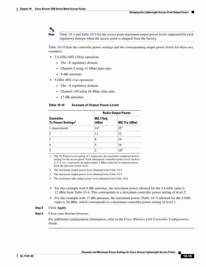
Chapter 10 Cisco Aironet 1520 Series Mesh Access Points Changing the Lightweight Access Point Output Power
Note Table 10-1 and Table 10-5 list the access point maximum output power levels supported for each regulatory domain when the access point is shipped from the factory.
Table 10-10 lists the controller power settings and the corresponding output power levels for these two examples:
• 2.4-GHz (802.11b/g) operation:
– The –E regulatory domain.
– Channel 3 using 11-Mbps data rates
– 8 dBi antennas
• 5-GHz (802.11a) operation:
– The –A regulatory domain
– Channel 149 using 48-Mbps data rates
– 17 dBi antennas
• For this example with 8 dBi antennas, the maximum power allowed for the 2.4-GHz radio is 12 dBm from Table 10-4. This corresponds to a maximum controller power setting of level 2.
• For this example with 17 dBi antennas, the maximum power (Table 10-7) allowed for the 5-GHz radio is 24 dBm, which corresponds to a maximum controller power setting of level 1.
Step 8 Click Apply.
Step 9 Close your Internet browser.
For additional configuration information, refer to the Cisco Wireless LAN Controller Configuration Guide.
Table 10-10 Example of Output Power Levels
Controller Tx Power Settings1
1. The Tx Power Level setting of 1 represents the maximum conducted power setting for the access point. Each subsequent controller power level (such as 2, 3, 4, etc.) represents an approximate 3-dBm reduction in transmit power from the previous power level.
Radio Output Power
802.11b/g (dBm) 802.11a (dBm)
1 (maximum) 142
2. The maximum output power level obtained from Table 10-1.
253
3. The maximum output power level obtained from Table 10-5.
2 11 22
3 8 19
4 5 16
5 2 164
4. The minimum radio output power level obtained from Table 10-8
10-15Channels and Maximum Power Settings for Cisco Aironet Lightweight Access Points
OL-11321-08

Chapter 10 Cisco Aironet 1520 Series Mesh Access Points Changing the Lightweight Access Point Output Power
10-16Channels and Maximum Power Settings for Cisco Aironet Lightweight Access Points
OL-11321-08