Channel Stability Assessment for Flood Control Projects
117
CECW-EH-D Engineer Manual 1110-2-1418 Department of the Army U.S. Army Corps of Engineers Washington, DC 20314-100 0 EM 1110-2-1418 31 October 1994 Engineering and Design CHANNEL STABILITY ASSESSMENT FOR FLOOD CONTROL PROJECTS Distribution Restriction Statement Approved for public release; distribution is unlimited.
Transcript of Channel Stability Assessment for Flood Control Projects

8/14/2019 Channel Stability Assessment for Flood Control Projects
http://slidepdf.com/reader/full/channel-stability-assessment-for-flood-control-projects 1/117
CECW-EH-D
Engineer Manual
1110-2-1418
Department of the Army
U.S. Army Corps of EngineersWashington, DC 20314-1000
EM 1110-2-1418
31 October 1994
Engineering and Design
CHANNEL STABILITY ASSESSMENT FOR
FLOOD CONTROL PROJECTS
Distribution Restriction Statement
Approved for public release; distribution is
unlimited.

8/14/2019 Channel Stability Assessment for Flood Control Projects
http://slidepdf.com/reader/full/channel-stability-assessment-for-flood-control-projects 2/117
EM 1110-2-141831 October 1994
US Army Corpsof Engineers
ENGINEERING AND DESIGN
Channel Stability Assessmentfor Flood Control Projects
ENGINEER MANUAL
8/14/2019 Channel Stability Assessment for Flood Control Projects
http://slidepdf.com/reader/full/channel-stability-assessment-for-flood-control-projects 3/117
DEPARTMENT OF THE ARMY EM 1110-2-1418U.S. Army Corps of Engineers
CECW-EH-D Washington, DC 20314-1000
ManualNo. 1110-2-1418 31 October 1994
Engineering and DesignCHANNEL STABILITY ASSESSMENT FOR
FLOOD CONTROL PROJECTS
1-1. Purpose. This manual provides assistance for determining potential channel instability andsedimentation effects in flood control projects. It is intended to facilitate consideration of the type andseverity of stability and sedimentation problems, the need for and scope of further hydraulic studies toaddress those problems, and design features to promote channel stability. The concept of channel
stability implies that the plan, cross-section, and longitudinal profile of the channel are economicallymaintainable within tolerable limits over the design life of the project. Causes and forms of instabilityare discussed in paragraph 3-3.
1-2. Applicability. This manual applies to all HQUSACE elements, major subordinate commands,districts, laboratories, and field operating activities having civil works responsibilities.
1-3. References. Required and related publications are listed in Appendix A.
FOR THE COMMANDER:

8/14/2019 Channel Stability Assessment for Flood Control Projects
http://slidepdf.com/reader/full/channel-stability-assessment-for-flood-control-projects 4/117
DEPARTMENT OF THE ARMY EM 1110-2-1418U.S. Army Corps of Engineers
CECW-EH-D Washington, DC 20314-1000
ManualNo. 1110-2-1418 31 October 1994
Engineering and DesignCHANNEL STABILITY ASSESSMENT FOR
FLOOD CONTROL PROJECTS
Table of Contents
Subject Paragraph Page Subject Paragraph Page
Chapter 1
IntroductionPurpose . . . . . . . . . . . . . . . . . . . . . . 1-1 1-1
Applicability . . . . . . . . . . . . . . . . . . . 1-2 1-1
References . . . . . . . . . . . . . . . . . . . . 1-3 1-1
Explanation of Terms . . . . . . . . . . . . . 1-4 1-1
General Approach . . . . . . . . . . . . . . . 1-5 1-1
Discussion . . . . . . . . . . . . . . . . . . . . 1-6 1-1
Systematic Approach to Channel
Stability . . . . . . . . . . . . . . . . . . . . . 1-7 1-1
Chapter 2Channel Stability Principles
Section I Characteristics of Channels in Erodible Materials
Geomorphic Context . . . . . . . . . . . . . 2-1 2-1
Common Channel Types . . . . . . . . . . . 2-2 2-2
Channel Geometry and Processes . . . . . 2-3 2-5
Section II
Principles of Channel Equilibrium and Response
Basic Concepts . . . . . . . . . . . . . . . . . 2-4 2-9
Applicability to Flood Control
Projects . . . . . . . . . . . . . . . . . . . . . 2-5 2-11
Response of Channels to AlteredConditions . . . . . . . . . . . . . . . . . . . 2-6 2-13
Channel Evolution and Geomorphic
Thresholds . . . . . . . . . . . . . . . . . . . 2-7 2-15
Chapter 3
Stability Problems with FloodControl Channels
Section I
Types of Channel Modification for Flood Control
General . . . . . . . . . . . . . . . . . . 3-1 3-1
Clearing and Snagging . . . . . . . 3-2 3-1
Cleanout . . . . . . . . . . . . . . . . . 3-3 3-1
Enlargement . . . . . . . . . . . . . . 3-4 3-2
Realignment . . . . . . . . . . . . . . 3-5 3-2
Levees . . . . . . . . . . . . . . . . . . 3-6 3-2
Flood Bypass Channels . . . . . . . 3-7 3-4
Flow Diversions . . . . . . . . . . . 3 -8 3-5
Section II
Case Examples of Stability Problems
Twenty Mile Creek . . . . . . . . . 3 -9 3-5
Puerco River . . . . . . . . . . . . . . 3-10 3-5
Grapevine Spillway Channel . . . 3-11 3-7
Snake River . . . . . . . . . . . . . . 3-12 3-8
Little Tallahatchie River . . . . . . 3-13 3-8
Red River . . . . . . . . . . . . . . . . 3-14 3-9
Sacramento River . . . . . . . . . . . 3-15 3-10
Long Creek Basin . . . . . . . . . . 3-16 3-10
Tanana River . . . . . . . . . . . . . . 3-17 3-11
i

8/14/2019 Channel Stability Assessment for Flood Control Projects
http://slidepdf.com/reader/full/channel-stability-assessment-for-flood-control-projects 5/117
EM 1110-2-141831 Oct 94
Subject Paragraph Page Subject Paragraph Page
Section III
Causes and Forms of Instability
General . . . . . . . . . . . . . . . . . . . . . . . 3-18 3-12
Continuation of Pre-existingProcesses, e.g., Meandering . . . . . . . 3-19 3-12
Increased Discharges . . . . . . . . . . . . . 3-20 3-15
Realignment and Channel
Improvement . . . . . . . . . . . . . . . . . . 3-21 3-15
Flow Regulation by
Reservoirs . . . . . . . . . . . . . . . . . . . 3-22 3-15
Sediment Transport and Channel
Stability . . . . . . . . . . . . . . . . . . . . . 3-23 3-16
Chapter 4
Assembly of Information for
Stability EvaluationGeneral . . . . . . . . . . . . . . . . . . . . . . . 4-1 4-1
Review of Historical Developments . . . 4-2 4-1
Map and Aerial Photo Interpretation . . . 4-3 4-2
Field Inspection . . . . . . . . . . . . . . . . . 4-4 4-2
Key Points and Features . . . . . . . . . . . 4-5 4-3
Channel and Floodplain Surveys . . . . . 4-6 4-8
Streamflow and Related Data . . . . . . . 4-7 4-10
Geologic and Geotechnical
Information . . . . . . . . . . . . . . . . . . . 4-8 4-11
Sediment Transport . . . . . . . . . . . . . . 4-9 4-12
Chapter 5
Evaluation of StabilityGeneral . . . . . . . . . . . . . . . . . . . . . . . 5-1 5-1
Levels of Detail . . . . . . . . . . . . . . . . . 5-2 5-1
Technical Approaches and Their
Application . . . . . . . . . . . . . . . . . . . 5-3 5-1
Allowable Velocity and Shear
Stress . . . . . . . . . . . . . . . . . . . . . . . 5-4 5-2
Empirical Relationships for Channel
Properties . . . . . . . . . . . . . . . . . . . . 5-5 5-7
Analytical Relationships for
Channel Properties . . . . . . . . . . . . . . 5-6 5-7
Sediment Transport and Sediment
Budget . . . . . . . . . . . . . . . . . . . . . . 5-7 5-10
Slope Stability . . . . . . . . . . . . . 5-8 5-13
Meander Geometry . . . . . . . . . 5-9 5-13
Basinwide Evaluation for
System Rehabilitation . . . . . . . 5-10 5-14
General Stepwise Approach . . . 5-11 5-16Checklist of Items to
Consider . . . . . . . . . . . . . . . . 5-12 5-16
Example of Qualitative
Evaluation . . . . . . . . . . . . . . 5-13 5-18
Chapter 6
Practical Aspects of Stability DesignGeneral . . . . . . . . . . . . . . . . . . 6-1 6-1
Ranking of Flood Control
Methods . . . . . . . . . . . . . . . . 6-2 6-1
Alignment and Planform . . . . . . 6-3 6-1
Single-Channel Streams . . . . . . 6-4 6-1
Multichannel Streams . . . . . . . . 6-5 6-3
Alluvial Fans . . . . . . . . . . . . . . 6-6 6-3
Longitudinal Profile and Grade
Controls . . . . . . . . . . . . . . . . 6-7 6-5
Cross Sections and Hydraulic
Capacities . . . . . . . . . . . . . . . 6-8 6-8
Control of Meandering . . . . . . . 6-9 6-13
Bank Protection . . . . . . . . . . . . 6-10 6-14
Control of Sediment
Deposition . . . . . . . . . . . . . . 6-11 6-15
Appendix A
References
Appendix B
Basis of Certain Charts in Paragraphs 5-4 and 5-5
Appendix CExamples of Quantitative Stability Evaluation
Appendix D
Notation
ii

8/14/2019 Channel Stability Assessment for Flood Control Projects
http://slidepdf.com/reader/full/channel-stability-assessment-for-flood-control-projects 6/117
EM 1110-2-141831 Oct 94
List of Figures
Figure Page Figure Page
1-1 Flowchart for systematic approach to
channel stability . . . . . . . . . . . . . . . . . . . 1-2
2-1 Drainage basin zones and some channel
types . . . . . . . . . . . . . . . . . . . . . . . . . . . 2-1
2-2 Typical longitudinal stream profile and
direction of change through time . . . . . . . 2-1
2-3 Mountain torrent . . . . . . . . . . . . . . . . . . . . 2-3
2-4 Alluvial fan . . . . . . . . . . . . . . . . . . . . . . . 2-3
2-5 Braided river . . . . . . . . . . . . . . . . . . . . . . 2-3
2-6 Arroyo . . . . . . . . . . . . . . . . . . . . . . . . . . 2-3
2-7 Meandering alluvial river . . . . . . . . . . . . . . 2-4
2-8 Incised channel . . . . . . . . . . . . . . . . . . . . . 2-5
2-9 Regulated river . . . . . . . . . . . . . . . . . . . . . 2-5
2-10 Delta . . . . . . . . . . . . . . . . . . . . . . . . . . . . 2-5
2-11 Some forms of stream planform . . . . . . . . . 2-7
2-12 Channel classification based on pattern and
type of sediment load . . . . . . . . . . . . . . . 2-8
2-13 Examples of meander shifting and bank
erosion . . . . . . . . . . . . . . . . . . . . . . . . . 2-8
2-14 Mechanisms of cross-sectional adjustment
to altered inputs of water and sediment . . . 2-8
2-15 Associations between slope, planform, and
bed material, Tanana River near
Fairbanks, Alaska . . . . . . . . . . . . . . . . . . 2-10
2-16 Processes of channel slope change . . . . . . . 2-11
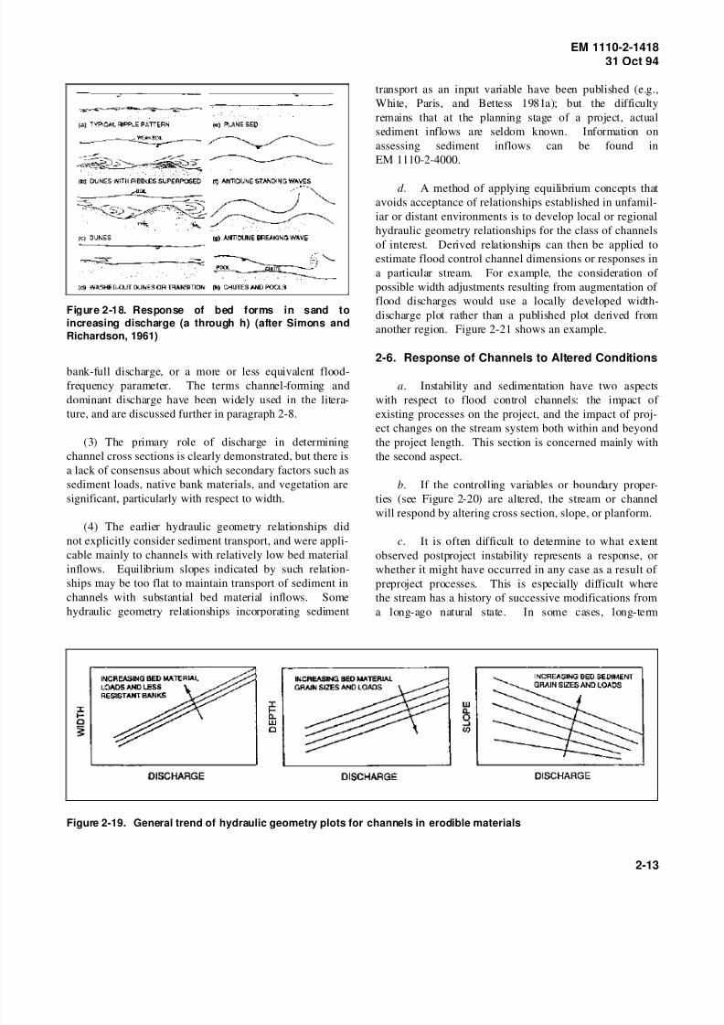
2-17 Bed forms in sand (Missouri River) . . . . . . 2-122-18 Response of bed forms in sand to increasing
discharge . . . . . . . . . . . . . . . . . . . . . . . . 2-13
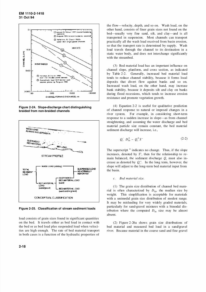
2-19 General trend of hydraulic geometry plots
for channels in erodible materials . . . . . . . 2-13
2-20 Generalized equilibrium concept for long-
term formation and response of
erodible channels . . . . . . . . . . . . . . . . . . 2-14
2-21 Width-discharge plot for specific local set
of channels . . . . . . . . . . . . . . . . . . . . . . 2-14
2-22 Example of complex profile response to
channelization . . . . . . . . . . . . . . . . . . . . 2-16
2-23 Channel evolution model for incised
channels . . . . . . . . . . . . . . . . . . . . . . . . 2-172-24 Slope-discharge chart distinguishing
braided from non-braided channels . . . . . . 2-18
2-25 Classification of stream sediment loads . . . . 2-18
2-26 Bed material grain size distributions and cor-
relation with slope (Tanana River near
Fairbanks, Alaska) . . . . . . . . . . . . . . . . . 2-19
2-27 Ice effects on banks of northern rivers . . . . . 2-20
2-28 Undercut bank erosion in frozen fine-
grained alluvium (Kuskokwim River,Alaska) . . . . . . . . . . . . . . . . . . . . 2-20
3-1 Clearing and snagging . . . . . . . . . . . 3-1
3-2 Channel enlargement . . . . . . . . . . . . 3-2
3-3 Channel enlargement by side berm
cut . . . . . . . . . . . . . . . . . . . . . . . 3-3
3-4 Forms of channel realignment . . . . . 3-3
3-5 Realigned channel without serious
instability problems . . . . . . . . . . . 3-3
3-6 Lateral instability in realigned
channel . . . . . . . . . . . . . . . . . . . . 3-3
3-7 Effects of levees on flood
hydrographs . . . . . . . . . . . . . . . . . 3-4
3-8 Bank protection necessitated by
encroachment on levee setback . . . . 3-4
3-9 Flood bypass channel formed by
high-level bend cutoffs . . . . . . . . . 3-4
3-10 Cross-section and profile responses
to channel enlargement, Twenty
Mile Creek . . . . . . . . . . . . . . . . . 3-6
3-11 Induced instability upstream of
channel enlargement, Twenty
Mile Creek . . . . . . . . . . . . . . . . . 3-7
3-12 Entrenched reach of Puerco River . . . 3-7
3-13 Grapevine Spillway Channel aftererosional episode . . . . . . . . . . . . . 3-7
3-14 Snake River near Jackson Hole . . . . 3-8
3-15 Response of Little Tallahatchie
River profile to upstream
reservoir . . . . . . . . . . . . . . . . . . . 3-9
3-16 Red River . . . . . . . . . . . . . . . . . . . 3-9
3-17 Specific gauge plot for Red River
at Shreveport, Louisiana, over
period 1982-1986 . . . . . . . . . . . . . 3-10
3-18 Flanking of experimental bank
protection on Sacramento River . . . 3-11
3-19 Incised channel in Long Creek
basin . . . . . . . . . . . . . . . . . . . . . . 3-123-20 Tanana River at Fairbanks showing
in-river levee and groins . . . . . . . . 3-13
3-21 Side bar deposition and sub-
meandering in straight channel . . . . 3-14
3-22 Sediment transport associated with
shifting of meander bends . . . . . . . 3-14
iii

8/14/2019 Channel Stability Assessment for Flood Control Projects
http://slidepdf.com/reader/full/channel-stability-assessment-for-flood-control-projects 7/117
EM 1110-2-141831 Oct 94
Figure Page Figure Page
3-23 Effect of storage reservoir on down-
stream flow-duration curve . . . . . . . . . . . 3-16
3-24 Effect of storage reservoir on down-
stream sediment transport (Missouri River
average annual suspended sediment load atOmaha, Nebraska) . . . . . . . . . . . . . . . . . 3-16
3-25 Effects of storage reservoir on profile
stability . . . . . . . . . . . . . . . . . . . . . . . . . 3-16
4-1 Aerial photograph of meandering river illus-
trating channel features . . . . . . . . . . . . . . 4-3
4-2 Comparison of modern (1986) and presettle-
ment (1830) channel locations, Fannegusha
Creek, Mississippi . . . . . . . . . . . . . . . . . 4-4
4-3 Major sediment source: valley landslide . . . 4-5
4-4 Tributary gully . . . . . . . . . . . . . . . . . . . . . 4-5
4-5 Stratification of bank soils . . . . . . . . . . . . . 4-6
4-6 Bank failure . . . . . . . . . . . . . . . . . . . . . . . 4-6
4-7 Piping and seepage in bank . . . . . . . . . . . . 4-6
4-8 Nick zone in degrading channel (clay
layer) . . . . . . . . . . . . . . . . . . . . . . . . . . 4-7
4-9 Channel bar with varous sediment classes
and debris . . . . . . . . . . . . . . . . . . . . . . . 4-7
4-10 Mouth of perched tributary . . . . . . . . . . . . 4-7
4-11 Exposed bridge piling . . . . . . . . . . . . . . . . 4-7
4-12 Flood stain marks on piers . . . . . . . . . . . . . 4-7
4-13 Example survey cross section . . . . . . . . . . . 4-8
4-14 Example of stream profile . . . . . . . . . . . . . 4-9
4-15 Grid photograph of coarse sediment and
comparison of analysis methods . . . . . . . . 4-10
5-1 Example of allowable velocity data with pro-
vision for sediment transport . . . . . . . . . . 5-2
5-2 Boundary shear stress in uniform flow . . . . 5-3
5-3 Shields diagram: dimensionless critical
shear stress . . . . . . . . . . . . . . . . . . . . . . 5-4
5-4 Example of allowable shear stresses (“trac-
tive forces”) for cohesive materials . . . . . . 5-4
5-5 Example of allowable velocity-depth data
for granular materials . . . . . . . . . . . . . . . 5-5
5-6 Insufficiency of allowable velocity or shear
stress criterion for stability of alluvial
channel . . . . . . . . . . . . . . . . . . . . . . . . . 5-65-7 Velocities and depths in compound cross
section . . . . . . . . . . . . . . . . . . . . . . . . . 5-6
5-8 Roughness changes in a large sand bed river
during floods . . . . . . . . . . . . . . . . . . . . . 5-6
5-9 Tentative guide to width-discharge relation-
ships for erodible channels . . . . . . . . . . . 5-8
5-10 Tentative guide to depth-discharge relation-
ships for erodible channels . . . . . . . . . . . 5-9
5-11 Tentative guide to slope-discharge
relationships for erodible
channels . . . . . . . . . . . . . . . . . . . 5-10
5-12 Infilling of oversized flood control
channel by deposition of sand infloods . . . . . . . . . . . . . . . . . . . . . 5-11
5-13 Comparison of computed and meas-
ured bed load in Tanana River
near Fairbanks, Alaska . . . . . . . . . 5-12
5-14 Mechanism of bank failure by
internal erosion . . . . . . . . . . . . . . 5-14
5-15 Stability analysis for steep
cohesive river banks . . . . . . . . . . . 5-15
5-16 Meander geometry . . . . . . . . . . . . . 5-15
5-17 Suggested relationshp between bank-
full (channel-forming) discharge
and meander wavelength for lay-
out of new channel . . . . . . . . . . . . 5-16
5-18 Distortion of meander pattern
upstream of protected length . . . . . 5-16
6-1 Regulated river with levees on
meandering alignment . . . . . . . . . . 6-3
6-2 Construction of a meandering
alignment . . . . . . . . . . . . . . . . . . 6-4
6-3 Alignment modifications to eroding
bends . . . . . . . . . . . . . . . . . . . . . 6-5
6-4 Alternative levee locations along
braided channel . . . . . . . . . . . . . . 6-5
6-5 Perched channel on aggradingalluvial fan . . . . . . . . . . . . . . . . . 6-5
6-6 Principal active source of fan bed
load may be downstream of
apex . . . . . . . . . . . . . . . . . . . . . . 6-5
6-7 Cross-slope interceptor channels
collecting flood flows from
adjacent alluvial fans . . . . . . . . . . 6-6
6-8 Use of grade controls to limit
profile degradation and downstream
sedimentation . . . . . . . . . . . . . . . . 6-7
6-9 Use of stepped sill on grade control
structure to match upstream rating
curve . . . . . . . . . . . . . . . . . . . . . 6-76-10 Classification of grade control
structures . . . . . . . . . . . . . . . . . . . 6-7
6-11 Sheet pile weir stabilizer . . . . . . . . . 6-9
6-12 Flume-type grade control/gauging
structure . . . . . . . . . . . . . . . . . . . 6-10
6-13 Drop structure with energy
dissipator . . . . . . . . . . . . . . . . . . . 6-10
iv

8/14/2019 Channel Stability Assessment for Flood Control Projects
http://slidepdf.com/reader/full/channel-stability-assessment-for-flood-control-projects 8/117
EM 1110-2-141831 Oct 94
Figure Page Figure Page
6-14 Debris basin and dam at head of alluvial
fan . . . . . . . . . . . . . . . . . . . . . . . . . . . . 6-10
6-15 Typical riser pipe grade control structure . . . 6-11
6-16 Concrete-lined channel on alluvial fan below
debris dam . . . . . . . . . . . . . . . . . . . . . . . 6-126-17 Various types of modified cross sections . . . 6-12
6-18 Compound cross section with low-flow
channel, grassed berms, and leaves . . . . . . 6-12
6-19 Increasing channel capacity in environ-
mentally sensitive areas . . . . . . . . . . . . . . 6-12
6-20 Selective clearing and snagging . . . . . . . . . 6-13
6-21 Redevelopment of meanders in straightened
channel following side bar development . . 6-14
6-22 Revetment necessitated by encroachment of
bank caving on levee . . . . . . . . . . . . . . . 6-14
6-23 Combined use of continuous toe protection
and intermittent groins . . . . . . . . . . . . . . 6-15
6-24 Extension of outer bank protection
downstream of inflection points . . . . . . . . 6-15
B-1 Consolidated width discharge plot by
Kellerhals and Church . . . . . . . . . . . . . . . B-3
B-2 Width-discharge plot by Hey and
Thorne, using bank vegetation as
basis of discrimination . . . . . . . . . B-4
B-3 Chart used as partial basis for
Figure 5-10 . . . . . . . . . . . . . . . . . B-5
C-1 Allowable shear stresses (tractive
forces) for canals in granular
materials . . . . . . . . . . . . . . . . . . . C-4
C-2 Varmint Creek channel properties
compared with tentative width,
depth, and slope charts from
paragraph 5-5 . . . . . . . . . . . . . . . . C-6
C-3 Slope versus width curves for dis-
charges of 4,500 cfs (Table C-4) and
51,000 cfs, based on output from
SAM program . . . . . . . . . . . . . . . C-9
v

8/14/2019 Channel Stability Assessment for Flood Control Projects
http://slidepdf.com/reader/full/channel-stability-assessment-for-flood-control-projects 9/117
EM 1110-2-141831 Oct 94
Chapter 1Introduction
1-1. Purpose
This manual provides assistance for determining potentialchannel instability and sedimentation effects in flood
control projects. It is intended to facilitate consideration
of the type and severity of stability and sedimentation
problems, the need for and scope of further hydraulic
studies to address those problems, and design features to
promote channel stability. The concept of channel stabil-
ity implies that the plan, cross-section, and longitudinal
profile of the channel are economically maintainable
within tolerable limits over the design life of the project.
Causes and forms of instability are discussed in
paragraph 3-3.
1-2. Applicability
This manual applies to all HQUSACE elements, major
subordinate commands, districts, laboratories, and field
operating activities having civil works responsibilities.
1-3. References
Required and related publications are listed in
Appendix A.
1-4. Explanation of Terms
Abbreviations used in this manual are explained in theNotation (Appendix D).
1-5. General Approach
The approaches presented in this manual are mainly quali-
tative and are intended to assist the engineer in the early
stages of project formulation to forecast the type and
magnitude of channel stability problems. Confidence in
the stability of the project design will be enhanced if
several different techniques of stability and sedimentation
evaluation are employed. Wherever possible, the proce-
dures employed should have been developed under
hydraulic and geomorphic conditions similar to thoseencountered in the project. If procedures appropriate to
project conditions do not seem to be available, or if dif-
ferent methods of evaluation do not give similar results, a
need for more sophisticated analyses may be indicated.
Such analyses might involve quantitative sediment trans-
port studies and numerical modelling of morphologic
response, which are not covered in this document.
Engineer Manual (EM) 1110-2-4000 suggests three stages
of sediment studies: sediment impact assessment, detailed
sedimentation study, and feature design sedimentation
study. This manual should be useful in the first stage of
the staged sedimentation study, and design guidance docu-
ments listed in Appendix A should be used in the second
and third stages. The reader should refer to EM 1110-2-
4000 for the risks and consequences of using the “stagedstudy” approach.
1-6. Discussion
Adverse effects of flood control modifications on channel
stability and sedimentation may be more common than is
generally known. Linder (1976) wrote:
“Once disturbed, a stream channel begins an
automatic and relentless process that culminates
in its reaching a new state of equilibrium with
nature....In the past, too many problems...have
been handled by modifying the river channelsinvolved without giving thought to the sediment
being transported by the water.... Techniques
should be employed that consider sediment trans-
port characteristics and stream equilibrium....The
ultimate cost of the uncontrolled erosion and
excessive downstream sediment deposition that
follow traditional channel modification is often
far greater than the initial cost of a design that
recognizes the influence of sediment transport
characteristics on a stre am’s state of
equilibrium.”
Channel instability and sedimentation in a flood controlproject are not always the result of project modifications
to the hydrology or channel characteristics. They may
also reflect the continuation of pre-existing conditions
such as meandering. Potential consequences of channel
instability, whether pre-existing or project-induced,
include reduction of assumed flood conveyance, loss of
land and structures, and excessive requirements for main-
tenance or rehabilitation.
1-7. Systematic Approach to Channel Stability
Solution of channel stability problems in the planning and
design of a flood control project requires the synthesis of field information, analytical procedures, and previous
experience in a complex fashion that cannot easily be
summarized as a linear sequence of steps. The flowchart
shown in Figure 1-1 is intended to convey how data
assessment and analysis can be integrated to attack
stability problems. Numbers within the diagram blocks
indicate subsequent paragraphs in this manual.
1-1

8/14/2019 Channel Stability Assessment for Flood Control Projects
http://slidepdf.com/reader/full/channel-stability-assessment-for-flood-control-projects 10/117
EM 1110-2-141831 Oct 94
Figure 1-1. Flowchart for systematic approach to channel stability
1-2

8/14/2019 Channel Stability Assessment for Flood Control Projects
http://slidepdf.com/reader/full/channel-stability-assessment-for-flood-control-projects 11/117
EM 1110-2-141831 Oct 94
Chapter 2Channel Stability Principles
Section 1
Characteristics of Channels in Erodible Materials
2-1. Geomorphic Context
a. In undertaking a stability and sedimentation
assessment of a proposed flood control channel project, it
is important to understand the relationship of the project
length to the stream system and the basin geomorphology,
and to see the project channel as part of an interlinked
system. Geomorphology here means the relationship of
stream channels and floodplains to the geology and
physiography of the region. Factors that have produced
the present channel features and will affect the response
of the channel to engineering works include sources and
supply of sediments, basin materials and vegetation, cata-
strophic events, earth movements, landslides, eruptions
and major floods, changes in land use and development,
and past interferences including structures, dredging, and
diking. The existing condition of the channel may depend
on factors far removed in space and time, and instability
response to flood control works may affect locations
beyond the project length far into the future.
b. In general terms, a drainage basin can be divided
into three main zones: an upper erosional zone of sedi-
ment production, a middle zone of sediment transport with
simultaneous erosion and deposition, and a lower zone of sediment deposition (Figure 2-1). The actual situation is
often more complex, because local geological controls or
other factors can produce local depositional zones in the
upper basin or local erosional zones in the lower basin.
Flood control projects are more common in the middle
and lower zones where the stream overflows frequently
onto agricultural or urban land. Methods of estimating
sediment production or yield are described in Chapter 3 of
EM 1110-2-4000.
c. In the general case, the longitudinal profile of the
stream system tends to flatten through time by degrada-
tion in the upper reaches and aggradation in the lowerreaches (Figure 2-2). In most natural systems this process
is slow enough to be of little engineering concern; but
where the stream system has been interfered with in the
historical period, profile flattening may be proceeding at
noticeable rates. In some channelization projects,
response of this type has been dramatic (see Chapter 3 for
examples).
Figure 2-1. Drainage basin zones and some channel
types
Figure 2-2. Typical longitudinal stream profile and
direction of change through time
d . Methods of investigating basin and channel
system geomorphology include examination of maps,
surveys, hydrologic records, and aerial photography and
satellite images; aerial and ground reconnaissance; study
of geological and soils reports; analytical methods; and
consultation with local residents and specialists. Theamount of study necessary or feasible depends on the
scale of the project and the judged severity of potential
instability problems. In the past, hydraulic design studies
for flood control channels often gave insufficient attention
to stability and sedimentation aspects. Where stability
was addressed, insufficient attention was given to long-
term effects and responses beyond the project area.
2-1

8/14/2019 Channel Stability Assessment for Flood Control Projects
http://slidepdf.com/reader/full/channel-stability-assessment-for-flood-control-projects 12/117
EM 1110-2-141831 Oct 94
e. Selected references on the geomorphology and
hydraulics of stream systems are listed in Appendix A.
2-2. Common Channel Types
A number of common channel types and their character-
istic stability problems are described below and sum-marized in Table 2-1.
a. Mountain torrents. These are high-velocity
streams on steep slopes, often exhibiting a sequence of
drops and chutes controlled by large boulders, fallen tim-
ber, etc. (Figure 2-3). Erosion and deposition are some-
times confined to severe flood events. Some mountain
torrents on very steep slopes are subject to the phenom-
enon of “debris flows” or “debris torrents” whereby under
severe flood conditions the bed becomes fluid and a
virtual avalanche of boulders and gravel runs down the
mountainside.
b. Alluvial fans.
(1) Alluvial fans generally occur where a stream
emerges from a mountain valley onto relatively flat land(Figure 2-4). They are depositional features usually char-
acterized by coarse alluvial materials and unstable multi-
ple channels subject to frequent shifts or “avulsions.”
The main channel is often “perched” on the highest
ground. Sometimes the alluvial fan is inactive deposition-
ally, and the stream is eroding into earlier deposits. They
are usually easily recognizable on aerial photographs and
sometimes on topographic maps. In wooded country they
are not always easily recognized on the ground.
Table 2-1
Some Stream Channel Types and Their Characteristic Stability Problems
Channel Type Typical Features Stability Problems
Mountain torrents Steep slopes Bed scour and degradation
Boulders Potential for debris flows
Drops and chutes
Alluvial fans Multiple channels Sudden channel shifts
Coarse deposits Deposition
Degradation
Braided rivers Interlacing channels Frequent shifts of main channel
Coarse sediments(usually) Scour and deposition
High bed load
Arroyos Infrequent flows Potential for rapid changes in planform, profile, and cross section.Wide flat channels
Flash floods
High sediment loads
Meandering rivers Alternating bends Bank erosion
Flat slopes Meander migration
Wide floodplains Scour and deposition
Modified streams Previously channelized Meander development
Altered base levels Degradation and aggradation
Bank erosion
Regulated rivers Upstream reservoirs Reduced activity
Irrigation diversions Degradation below dams
Lowered base level for tributariesAggradation at tributary mouths
Deltas Multiple channels Channel shifts
Fine deposits Deposition and extension
Underfit streams Sinuous planform Meander migration
Low slope
Cohesive channels Irregular or unusual planform Variable
2-2
8/14/2019 Channel Stability Assessment for Flood Control Projects
http://slidepdf.com/reader/full/channel-stability-assessment-for-flood-control-projects 13/117
EM 1110-2-141831 Oct 94
Figure 2-3. Mountain torrent
Figure 2-4. Alluvial fan
(2) Potential stability problems on alluvial fans
include avulsion of the stream at a point upstream of
training works or channelization, thereby bypassing the
works, and infilling of the designed conveyance channel
by coarse sediment deposits. Flood control works should
be carried sufficiently far upstream and consideration
should be given to trapping or removal of coarse sediment
upstream of the flood control zone. Location of the flood
control channel requires consideration of local features
and processes.
c. Braided rivers. Braided rivers consist of a net-
work of interlacing channels with unstable bars and
islands (Figure 2-5). They generally occur in the upper
and upper-middle zones of a basin. Bed materials are
usually gravels or cobbles, but braided sand rivers are
found occasionally. Bed material transport tends to be
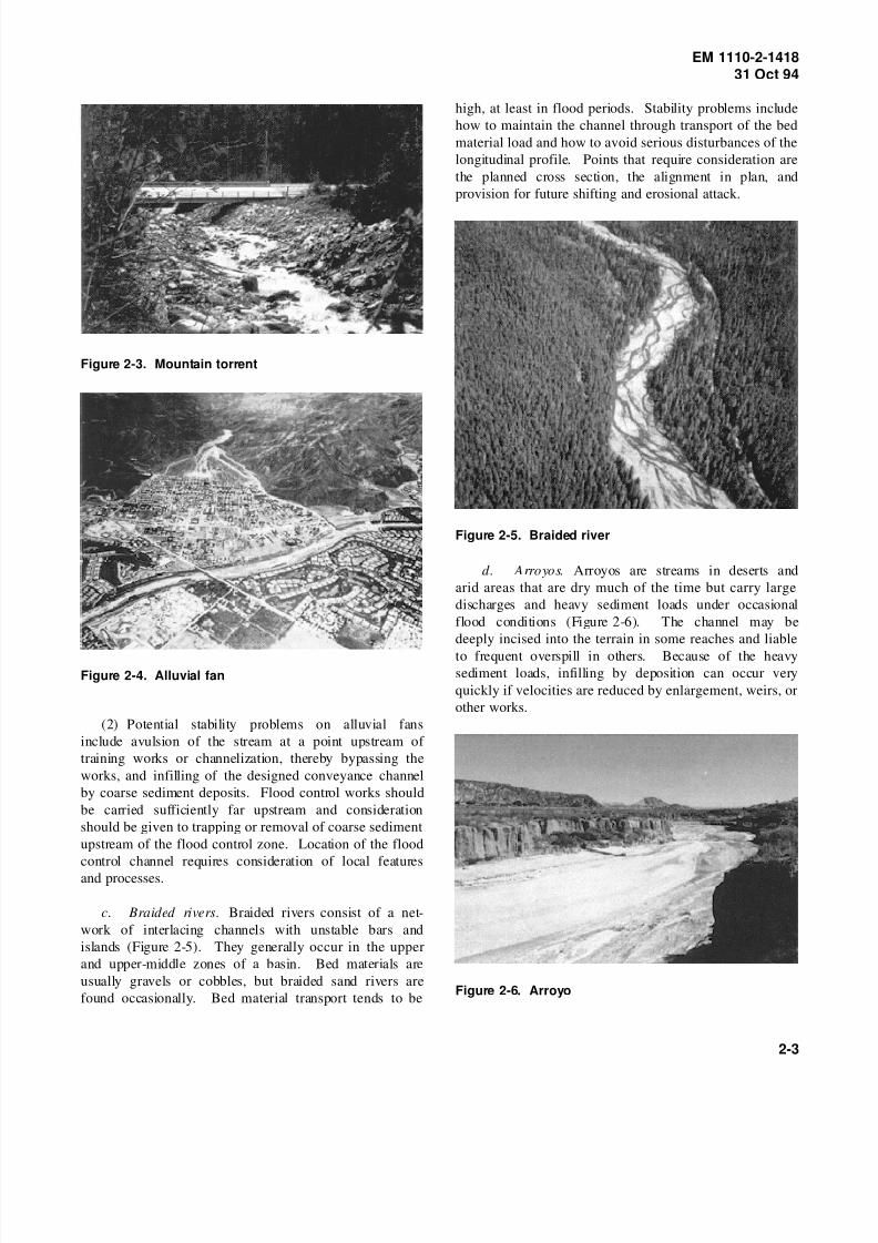
high, at least in flood periods. Stability problems include
how to maintain the channel through transport of the bed
material load and how to avoid serious disturbances of the
longitudinal profile. Points that require consideration are
the planned cross section, the alignment in plan, and
provision for future shifting and erosional attack.
Figure 2-5. Braided river
d. Arroyos. Arroyos are streams in deserts and
arid areas that are dry much of the time but carry large
discharges and heavy sediment loads under occasional
flood conditions (Figure 2-6). The channel may be
deeply incised into the terrain in some reaches and liable
to frequent overspill in others. Because of the heavysediment loads, infilling by deposition can occur very
quickly if velocities are reduced by enlargement, weirs, or
other works.
Figure 2-6. Arroyo
2-3

8/14/2019 Channel Stability Assessment for Flood Control Projects
http://slidepdf.com/reader/full/channel-stability-assessment-for-flood-control-projects 14/117
EM 1110-2-141831 Oct 94
e. Meandering alluvial rivers.
(1) These generally occur in the middle and lower
zones of a basin. The single channel follows a character-
istic sinuous planform and is normally eroding into the
floodplain on one bank and creating new floodplain by
deposition on the opposite bank. Bed material is usuallysand or sand and gravel. In undisturbed natural systems,
future shifting of the channel is often predictable from
comparison of sequential maps or aerial photographs. In
many cases the traces of former channel locations are
detectable on aerial photographs (Figure 2-7).
(2) Numerous stability and sedimentation problems
may arise from flood control works on meandering
streams. Flood control may involve straightening, regu-
lation or augmentation of flows, and alteration of sedi-
ment loads. Meandering systems are often sensitive to
modest imposed changes and can respond with trouble-
some alterations of cross sections, planforms, and gradi-ents. Planning requires consideration of past channel
behavior, of likely responses, and of the advisability of
stabilization measures.
f. Modified streams.
(1) In some regions, many streams have been modi-
fied in the past by human activity and do not much
resemble natural rivers. A common form of modification
is straightening or enlargement for flood control; but if
the changes occurred many decades ago, the details may
be difficult to discover. Another form of modification is
by flood control works or reservoirs on a parent river,
which produced changes in the stream of interest by alter-
ing base levels.
(2) A particular regional type of modified stream isexemplified by the incised channels of northern Missis-
sippi (Figure 2-8). These are hill streams in erodible soils
that often have a long history of response to widespread
basin erosion following land-use changes, channelization,
and/or altered base levels. Planning of flood control
works on a stream of this type should take into account
its present state of evolution toward a new equilibrium.
g. Regulated rivers. These are generally streams
where the flood discharges have been reduced and the low
flows increased by upstream storage reservoirs (Fig-
ure 2-9). Such streams often exhibit a reduction in mor-
phologic activity compared with previous naturalconditions, and the cross sections of their channels may
have been reduced by deposition of sediment and
encroachment of vegetation. But if the stream under
natural conditions carried substantial loads of bed mate-
rial, trapping of sediment in reservoirs may initiate slope
changes downstream. The effects of regulation on stabil-
ity are thus complex and depend on the previous charac-
teristics of the stream as well as on the degree and mode
of regulation.
Figure 2-7. Meandering alluvial river
2-4

8/14/2019 Channel Stability Assessment for Flood Control Projects
http://slidepdf.com/reader/full/channel-stability-assessment-for-flood-control-projects 15/117

8/14/2019 Channel Stability Assessment for Flood Control Projects
http://slidepdf.com/reader/full/channel-stability-assessment-for-flood-control-projects 16/117
EM 1110-2-141831 Oct 94
a. Planforms.
(1) Stream planforms were once roughly classified as
braided, meandering, and straight; but a wide variety of
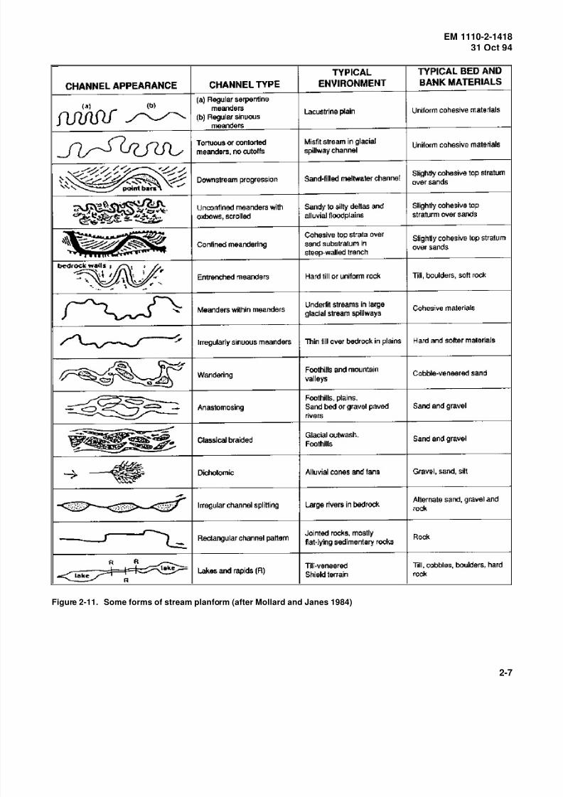
natural forms are now recognized. Figure 2-11 shows a
more extended set of descriptions with associated environ-
mental conditions.
(2) Relationships between planform and other aspects
of geometry and processes are difficult to systematize,
although often appreciated intuitively from long experi-
ence of river observation. For example, braided rivers are
usually wide and shallow, and the limits of the braided
area tend to remain relatively stable. Certain types of
sinuous planform generally indicate a systematic process
of down-valley meander migration, while others indicate a
process of periodic bend cutoffs. Streams with highly
contorted meandering planforms tend to have relatively
flat slopes and low width-to-depth ratios. Figure 2-12
attempts to summarize available information on channelpattern, type, and associated variables, and Figure 2-13
illustrates various forms of meander shifting. The total
length of most natural streams does not change
appreciably over time despite dynamic changes in plan-
form and channel location. For example, local shortening
produced by occasional meander bend cutoffs is usually
compensated for by gradual lengthening of other bends.
Where overall shortening is imposed, the stream often
responds by attacking banks and developing new
meanders in an attempt to restore the original length.
b. Cross sections.
(1) The cross section of a natural channel depends on
basin runoff, sediment input, and boundary soils and
vegetation, as explained further in Section II. Under
natural conditions the average cross section usually does
not change much over a period of years, but it may alter
temporarily in severe floods. Systematic trends of
enlargement or shrinkage usually result from changes in
discharge or sediment inputs as a result of basin changes
or on-stream works. The variability of cross sections
from point to point along the channel depends on many
factors: it may be quite small in stable nearly-straight
channels, and very large in highly active channels of
complex planform.
(2) The process of cross-section enlargement by ero-
sion is easy to visualize. The mechanism of shrinkage is
less easy to visualize and varies considerably (Fig-
ure 2-14). In a more or less straight channel, it can occur
as a result of deposition of suspended sediment on the
banks and subsequent colonization by vegetation. In a
shifting meandering channel, shrinkage will occur if the
rate of deposition on the inner bank of bends exceeds rate
of erosion on the outer bank.
(3) A method for comparing cross sections along a
channel reach, or for establishing an average cross section
to estimate overall channel characteristics, is to establish asloping reference plane parallel with the average water
surface of a substantial but within-bank flow. The eleva-
tion of the reference plane is then transferred to each
cross section for visual comparison of sections relative to
the plane. Widths and areas can be determined at various
levels above and below the reference plane, and can be
averaged to indicate average section properties at various
levels relative to the plane. The same reference plane
should be used as a basis for successive surveys to com-
pare changes over time.
(4) When hydraulic computations of channel capaci-
ties and water surface profiles are made for active mobile-boundary streams, it is important to realize the transitory
nature of cross sections. Although the average channel
cross section over a long reach may be similar under low-
water and flood conditions, individual cross sections may
change substantially according to the stage of flow. For
example, bends and scour holes in meandering channels
normally deepen in floods, and points of inflection
(“crossings”) tend to shoal. When water surface profiles
are modelled using standard computational procedures
based on fixed boundaries, boundary mobility must be
considered and a sensitivity analysis performed if
necessary.
(5) Further hydraulic difficulties with unstable cross
sections arise when in-channel flows are to be systemati-
cally increased as a result of flood control, for example,
by construction of floodplain levees close to the channel.
If the channel is left in its natural state, it may enlarge
systematically over a period of time as a result of erosion
by the increased flows. Actual flood levels would then
tend to be lower than those computed using existing cross
sections. On the other hand, if the channel is designed to
be enlarged by excavation, the cross sections provided
may be partly infilled by sediment deposition, in which
case actual flood levels would be higher than computed.
A common error in designing modified channels for flood
control is to provide too large a cross section, intended to
carry a rare flood without overbank flow. Such a cross
section is unlikely to maintain itself because it partly
infills with sediment under more frequent flood condi-
tions. Although a need for dredging or excavation to
maintain the enlarged channel may be recognized and
provided for in project agreements, experience has shown
2-6
8/14/2019 Channel Stability Assessment for Flood Control Projects
http://slidepdf.com/reader/full/channel-stability-assessment-for-flood-control-projects 17/117
EM 1110-2-141831 Oct 94
Figure 2-11. Some forms of stream planform (after Mollard and Janes 1984)
2-7

8/14/2019 Channel Stability Assessment for Flood Control Projects
http://slidepdf.com/reader/full/channel-stability-assessment-for-flood-control-projects 18/117
EM 1110-2-141831 Oct 94
Figure 2-12. Channel classification based on pattern
and type of sediment load (Schumm and Meyer 1979,
courtesy of Simons, Li & Associates)
Figure 2-13. Examples of meander shifting and bank
erosion (Brice 1984, courtesy of American Society of
Civil Engineers)
Figure 2-14. Mechanisms of cross-sectional adjust-
ment to altered inputs of water and sediment
that it is often difficult to enforce such maintenance
obligations.
c. Slopes and profiles.
(1) The longitudinal profile of a stream is only
partly determined by the landscape. The channel is flatter
than the valley slope unless the channel is straight. In
many cases, the channel slope represents a long-term
equilibrium condition. When a meandering stream is
straightened, a steeper non-equilibrium slope is tempo-
rarily imposed. Responses in the form of erosion and
deposition are then set in motion, in the direction of
restoring equilibrium.
(2) The slope of a stream usually flattens gradually
from source to mouth. However, local anomalies due to
geological controls and other factors are common; for
example, the slope will be flatter upstream of a bedrock
sill, and steeper below a tributary that delivers quantities
2-8

8/14/2019 Channel Stability Assessment for Flood Control Projects
http://slidepdf.com/reader/full/channel-stability-assessment-for-flood-control-projects 19/117
EM 1110-2-141831 Oct 94
of coarse sediment. Reduction of slope from head to
mouth along a stream is related to changes in other char-
acteristics; sometimes changes are relatively abrupt
(Figure 2-15).
(3) Processes of channel profile change through time
at rates of engineering concern are usually referred to asaggradation and degradation (Figure 2-16). For example,
aggradation tends to progress upstream from a dam or
grade control structure, and degradation to progress
downstream from a structure that traps sediment.
(4) A process referred to as headcutting, common in
channelized streams, involves degradation progressing
upstream, often accompanied by aggradation progressing
downstream. The upstream end of a headcut is called a
nick point, or nick zone if it extends some distance along
the stream.
d. Bed topography and roughness.
(1) The bed topography and hydraulic roughness of
natural channels may vary greatly along the channel and
also with stage of flow. The total hydraulic resistance
results from a combination of grain roughness and form
roughness. Form roughness can arise from bed and bank
irregularities and from changes in planform. In active
sand channels, bed forms may range from small ripples a
few inches in height, to dunes a few feet in height, to
larger waves and bars (Figure 2-17). These forms depend
on flow conditions and mainly control the hydraulic
roughness of the bed. Also, the bed topography at any
time depends on the preceding flow history as well as onpresent conditions. Roughness therefore varies with stage
and is not always the same at similar stages - one reason
for the looped or erratic stage-discharge curves found in
many alluvial streams. Other important sources of form
roughness are trees and bushes, river bank protection and
structures, floodplain obstructions, bedrock outcrops,
bends and scour holes, and abrupt changes in cross
section.
(2) Channels formed in coarser sediments have differ-
ent and often more stable forms of bed topography than
sand-bed channels. In gravel-bed streams, the dominant
form of bed topography tends to be an alternation of
pools and riffles: the pools are characterized by flatter
local slopes and finer bed materials, and the riffles by
steeper slopes and coarser materials. Bar characteristics
and flow resistance in coarse-bed streams are described by
various authors (Hey, Bathurst, and Thorne 1982).
Armoring, whereby the material on the bed surface is
coarser than the underlying material, is described in a
related publication (Thorne, Bathurst, and Hey 1987).
Some of the features of natural gravel rivers tend to
develop in channelized rivers and artificial channels.
Armoring is common in regulated streams downstream of
storage reservoirs.
(3) When discharges are augmented by flood controlworks, the prevailing type of bed topography may alter
significantly. For example, steep sand streams with high
sand transport undergo an abrupt change at a certain flow
threshold, whereby the bed forms “wash out” and a more
or less flat bed with reduced roughness results (Fig-
ure 2-18). This phenomenon tends to reduce flood levels,
but to increase velocities with adverse consequences for
channel stability. It may cause abrupt anomalies in stage-
discharge curves. In some sand-bed channels, bed topog-
raphy and roughness may also respond to changes in
water temperature at a constant flow.
Section II Principles of Channel Equilibrium and Response
2-4. Basic Concepts
a. The concept that the cross section and slope of a
sediment-transporting channel in erodible materials tend to
be in a state of equilibrium was developed more or less
independently by engineers seeking to design unlined
canals that would neither silt nor scour, and by geomor-
phologists studying the relationship of river channel
geometry to hydrologic and environmental factors. The
engineering concept was initially expressed by the term
regime channel and the geomorphologic concept by theterm graded river. Some key quotations are as follows:
(1) When an artificial channel is used to convey silty
water, both bed and banks scour and fill, changing depth,
gradient and width, until a state of balance is attained at
which the channel is said to be in regime (Lindley 1919).
(2) The graded stream is one in which, over a period
of years, slope is delicately adjusted to provide, with
available discharge and with prevailing channel charac-
teristics, just the velocity required for transportation of the
load from the drainage basin (Mackin 1948).
(3) Similar equations (for hydraulic geometry) apply
both to rivers and to stable (“regime”) irrigation canals
which neither scour nor aggrade their beds. The analogy
demonstrates that the average river channel-system tends
to develop in a way to produce an approximate equili-
brium between the channel and the water and sediment it
must transport (Leopold and Maddock 1953).
2-9

8/14/2019 Channel Stability Assessment for Flood Control Projects
http://slidepdf.com/reader/full/channel-stability-assessment-for-flood-control-projects 20/117
EM 1110-2-141831 Oct 94
Figure 2-15. Associations between slope, planform, and bed material, Tanana River near Fairbanks, Alaska (from
Buska et al. 1984)
2-10

8/14/2019 Channel Stability Assessment for Flood Control Projects
http://slidepdf.com/reader/full/channel-stability-assessment-for-flood-control-projects 21/117
EM 1110-2-141831 Oct 94
Figure 2-16. Processes of channel slope change
b. The equilibrium or regime concept has been
tested against sets of river and canal data from various
parts of the world (see Graf 1984, Mahmood and Shen
1971, Nunnally and Shields 1985). Channel widths,
depths, and slopes are usually plotted independently
against a characteristic discharge. Plots are sometimes
stratified according to bed material size or other factors.Curves or equations are fitted and recommended for vari-
ous analysis and design purposes. The general trend of
plots by various investigators is illustrated in Figure 2-19.
c. The regime concept to stability assessment and
channel design is essentially empirical. It has been
regarded cautiously by many hydraulic engineers because
of lack of theoretical verification and sometimes because
relationships derived from one region did not fit experi-
ence elsewhere. Stevens and Nordin (1987) criticize
various aspects of the traditional approach, but conclude:
“Lindley’s regime concept that an alluvial channel adjusts
its width, depth and slope in accordance to the amount of
water and the amount and kind of sediment supplied
remains unchallenged here. Regime channels are those
flowing in their own sediment.”
d . Because the term regime has given rise to some
confusion and controversy, it will be avoided herein
where possible. The concept embodied in the quotations
in a above will be called the equilibrium concept of chan-
nel formation and response. Relationships of channel
dimensions and slope to discharge and other parameters
will be called hydraulic geometry. The user should be
aware, however, that much literature from other countries
refers to the regime concept or theory, and to regime
relationships, with more or less the same generalmeanings.
e. The term stable channel has been used exten-
sively in the engineering literature but is also subject to
confusion. It is often used to mean a channel that has
attained stability of width, depth, and slope. Such a chan-
nel, however, may be actively meandering, in which case
it is not stable in planform. To avoid confusion, the term
is generally avoided in this EM.
2-5. Applicability to Flood Control Projects
a. Reduced to essentials, the equilibrium conceptimplies that stable width, depth, and slope (and perhaps
planform) can be expressed as functions of controlling
variables: discharge, boundary materials, and sediment
supply (Figure 2-20). Hydraulic geometry relationships
may be useful in the planning stages of a flood control
project for comparing alternatives and assessing certain
stability problems.
b. The concept of degrees of freedom is sometimes
useful for visualizing forms of potential instability in
erodible channels caused by changes in controlling vari-
ables. As a general case, a channel may have at least
four degrees of freedom; that is, it can adjust its planform,width, depth, and slope. Other factors such as roughness,
bank line shift rates, and sediment transport may also
adjust.
c. Some features and difficulties of the equilibrium
concept are discussed as follows:
(1) Hydraulic geometry relationships (Figure 2-19)
usually deal with width, depth, and slope, but not plan-
form. Stability problems related to planform, for exam-
ple, whether meanders will develop in an initially straight
channel, therefore seem to be outside the scope of tradi-
tional equilibrium concepts. Meander geometry is dis-
cussed in paragraph 5-9.
(2) Most hydraulic geometry relationships use a sin-
gle characteristic discharge, intended to be representative
of the actual varying discharges, as a primary independent
variable. In natural streams this is often taken as the
2-11

8/14/2019 Channel Stability Assessment for Flood Control Projects
http://slidepdf.com/reader/full/channel-stability-assessment-for-flood-control-projects 22/117
EM 1110-2-141831 Oct 94
Figure 2-17. Bed forms in sand (Missouri River)
2-12
8/14/2019 Channel Stability Assessment for Flood Control Projects
http://slidepdf.com/reader/full/channel-stability-assessment-for-flood-control-projects 23/117
EM 1110-2-141831 Oct 94
Figure 2-18. Response of bed forms in sand to
increasing discharge (a through h) (after Simons and
Richardson, 1961)
bank-full discharge, or a more or less equivalent flood-
frequency parameter. The terms channel-forming and
dominant discharge have been widely used in the litera-
ture, and are discussed further in paragraph 2-8.
(3) The primary role of discharge in determining
channel cross sections is clearly demonstrated, but there is
a lack of consensus about which secondary factors such as
sediment loads, native bank materials, and vegetation are
significant, particularly with respect to width.
(4) The earlier hydraulic geometry relationships did
not explicitly consider sediment transport, and were appli-cable mainly to channels with relatively low bed material
inflows. Equilibrium slopes indicated by such relation-
ships may be too flat to maintain transport of sediment in
channels with substantial bed material inflows. Some
hydraulic geometry relationships incorporating sediment
transport as an input variable have been published (e.g.,
White, Paris, and Bettess 1981a); but the difficulty
remains that at the planning stage of a project, actual
sediment inflows are seldom known. Information on
assessing sediment inflows can be found in
EM 1110-2-4000.
d . A method of applying equilibrium concepts that
avoids acceptance of relationships established in unfamil-
iar or distant environments is to develop local or regional
hydraulic geometry relationships for the class of channels
of interest. Derived relationships can then be applied to
estimate flood control channel dimensions or responses in
a particular stream. For example, the consideration of
possible width adjustments resulting from augmentation of
flood discharges would use a locally developed width-
discharge plot rather than a published plot derived from
another region. Figure 2-21 shows an example.
2-6. Response of Channels to Altered Conditions
a. Instability and sedimentation have two aspects
with respect to flood control channels: the impact of
existing processes on the project, and the impact of proj-
ect changes on the stream system both within and beyond
the project length. This section is concerned mainly with
the second aspect.
b. If the controlling variables or boundary proper-
ties (see Figure 2-20) are altered, the stream or channel
will respond by altering cross section, slope, or planform.
c. It is often difficult to determine to what extentobserved postproject instability represents a response, or
whether it might have occurred in any case as a result of
preproject processes. This is especially difficult where
the stream has a history of successive modifications from
a long-ago natural state. In some cases, long-term
Figure 2-19. General trend of hydraulic geometry plots for channels in erodible materials
2-13

8/14/2019 Channel Stability Assessment for Flood Control Projects
http://slidepdf.com/reader/full/channel-stability-assessment-for-flood-control-projects 24/117
EM 1110-2-141831 Oct 94
Figure 2-20. Generalized equilibrium concept for long-
term formation and response of erodible channels
Figure 2-21. Width-discharge plot for specific local set
of channels. (Note: 10-year discharge used because
of special local circumstances)
responses to a historical sequence of interferences may be
extremely difficult to distinguish.
d . Although initial response may occur mainly
within the project length, long-term response may affect
the stream system far upstream and downstream,
including tributaries and distributaries. Where a preproj-
ect stability assessment indicates potential problems, stabi-
lization measures such as bank protection, grade control
structures, and sediment basins are often incorporated in
the design. This will not necessarily eliminate upstream
or downstream responses. For example, if a stream has
migrating meander bends, stabilizing the bends within theproject length may impact on bend migration processes
upstream and downstream.
e. Table 2-2 indicates the general direction in
which channel characteristics can be expected to respond
to changes in driving variables or boundary conditions
(see also Figure 2-19).
f . Some additional comments are as follows:
(1) Widths generally vary more or less as the square
root of discharges, other things being equal. Widening in
response to increased flood discharges can generally beexpected. In the case of reduced discharges, ultimate
narrowing can be expected if the channel carries enough
sediment to deposit on the banks or on side bars.
(2) In the case of meandering planforms, meander
wavelength tends to maintain a more or less constant rela-
tionship to channel width. Increased flood discharges
therefore tend to increase meander wavelength as well as
width.
(3) The response of width to changes in bed material
inflows is indicated as unclear. Generally, channels with
relatively high bed material loads tend to be wider, but achannel with erosion-resistant banks will not necessarily
widen in response to increased load.
(4) Depths increase with increasing discharges, but
not so much as widths (Figure 2-19). Depths will gen-
erally decrease with increased bed material inflow, as
slopes increase (see (5) below).
(5) Slopes vary inversely with discharges (Fig-
ure 2-19), and tend to reduce by degradation if flood
discharges are increased. Slopes tend to increase by
aggradation if bed material inflows are increased, and
depths reduce correspondingly. Increases in discharge
and in bed material input therefore have opposite effects
on slope and may largely cancel out if they occur toge-
ther, for example, as a result of upstream deforestation.
(6) The most widely known geomorphic relationship
embodying slope and the equilibrium concept is known as
Lane’s (1955) principle and can be expressed in the form:
2-14

8/14/2019 Channel Stability Assessment for Flood Control Projects
http://slidepdf.com/reader/full/channel-stability-assessment-for-flood-control-projects 25/117
EM 1110-2-141831 Oct 94
Table 2-2
Expected Response of Channel Characteristics to Changes in Driving Variables or Environmental Conditions (see Figure 2-19)
Expected Change in Channel Characteristics (Exceptions May Occur)
Variable Subject
to Imposed
Change
Nature of
Change Width Depth Slope Platform Type Bank Erosion
Discharges Increased Increased Increased Reduced No marked
change
Increased
Reduced Reduced or
unchanged1
Reduced Increased or
unchanged1
No marked
change
Reduced
Bed-sediment
inflows
Increased Unclear Reduced Marked increase Increased bars
and channel
splitting
May increase
Reduced Unclear Increased Reduced Less channel
splitting
May reduce
Bed-sediment
grain size
Increased Insignificant Reduced Marked increase Unclear Unclear
Reduced Insignificant Increased May reduce Unclear Unclear
Bank conditions Add bank
protection
May reduce May increase
locally
No marked
change
As imposed Reduced locally,
may increase
downstream
Removal
of woody
vegetation
Increased May reduce No change Increased bars Marked increase
1 Depending on availability of sediment for deposition.
(2-1)QS ∼ Qs
D50
where
Q = discharge, ft3 /sec
S = slope, ft/ft
Qs = bed material discharge, tons/day
D50 = median sediment size, ft
This form of relationship indicates that imposed increases
in slope lead to an increase in sediment transportassuming the water discharge and sediment size remain
constant. If a sinuous channel is straightened, an
increased slope is imposed, and increased bed material
transport occurs out of the straightened reach, causing
degradation upstream and aggradation downstream. The
channel thereby attempts to reestablish the original slope.
(7) Channel planform type responds to changes in
bed material input if discharges remain unchanged.
Generally, increasing bed material loads produces a more
disorganized pattern with exposed bars. A densely
braided pattern is the extreme example.
(8) Bank erosion and channel shift rates are sensitive
to increased in-channel discharges and reduced bank resis-
tance, particularly removal of woody vegetation. (Flood
control levees may be an important reason for increased
in-channel discharges.)
2-7. Channel Evolution and GeomorphicThresholds
a. The sequence of responses to certain imposed
changes, for example channelization, can be quite com-
plex. An initial profile response may involve temporary
aggradation while a later or final condition may involve
degradation below original levels (Figure 2-22).
2-15

8/14/2019 Channel Stability Assessment for Flood Control Projects
http://slidepdf.com/reader/full/channel-stability-assessment-for-flood-control-projects 26/117

8/14/2019 Channel Stability Assessment for Flood Control Projects
http://slidepdf.com/reader/full/channel-stability-assessment-for-flood-control-projects 27/117
EM 1110-2-141831 Oct 94
Figure 2-23. Channel evolution model for incised channels (Schumm, Harvey, and Watson 1984, Courtesy of Water
Resources Publications)
2-17
8/14/2019 Channel Stability Assessment for Flood Control Projects
http://slidepdf.com/reader/full/channel-stability-assessment-for-flood-control-projects 28/117

8/14/2019 Channel Stability Assessment for Flood Control Projects
http://slidepdf.com/reader/full/channel-stability-assessment-for-flood-control-projects 29/117
EM 1110-2-141831 Oct 94
Figure 2-26. Bed material grain size distributions and correlation with slope (Tanana River near Fairbanks, Alaska)
(from Buska et al. 1984).
categories is virtually absent, the two distributions show
D50 values of 8 mm and 0.4 mm, respectively, which
greatly exaggerate the overall difference. When the D75
size, which falls clearly into the gravel range, was used to
represent the bed material distribution, a good correlation
was obtained with slope variation along the river
(Figure 2-26b).
(3) The channel characteristic most sensitive to bed
material size is slope. For example, channels in coarse
gravel and fine sand, respectively, equal in terms of chan-nel-forming discharges and sediment inflows, might have
slopes differing by more than one order of magnitude.
The coarser and steeper channel would also have smaller
depths and higher velocities. The influence of bed mate-
rial size on widths is relatively small and difficult to
separate from other factors.
d. Bank materials and vegetation. These factors
may affect channel width, planform stability, and rates of
channel migration.
(1) For fully alluvial streams flowing within an enve-
lope of self-deposited sediments, it is debatable whether
bank materials should be considered as independent fac-
tors affecting channel characteristics (Figure 2-20). Vege-
tation, however, is more clearly an independent factor.
Instability is often triggered by the clearing of vegetation
from streambanks, and sometimes by eroded and deadfall
vegetation within the channel. The role of bank
vegetation varies greatly with the region and type of
vegetation. Vegetation established on bars during low-
flow periods can have a significant effect on channel
capacity and processes. Vegetation has been treated as a
variable in some hydraulic geometry relationships (Hey
and Thorne 1986).
(2) Many erodible stream channels are bounded
wholly or partly by clay, compacted silt and loess, glacial
till, or glaciofluvial deposits laid down in earlier geologi-
cal periods. Although channel widths in such cases areoften similar to those of alluvial streams, responses to
imposed changes tend to be slower. Analogy with similar
cases in the region of interest is the best guide to predict-
ing response.
(3) The effect of geotechnical bank stability on
channel characteristics is important in some environments.
River engineers have tended to regard bank instability
more as a consequence than a cause of channel instability,
the reasoning being that collapse of the upper bank is
initiated by hydraulic scour at the toe. Geotechnical
mechanisms, however, appear to be significant primary
causes of alluvial bank failures within certain large drain-
age basins. Hagerty (1992) discusses sequences of allu-
vial bank failure and erosion of failed soil along streams
and rivers. According to Thorne and Osman (1988), bank
stability characteristics affect hydraulic geometry in both
straight and meandering channels. This topic is discussed
further in paragraph 5-9.
2-19

8/14/2019 Channel Stability Assessment for Flood Control Projects
http://slidepdf.com/reader/full/channel-stability-assessment-for-flood-control-projects 30/117
EM 1110-2-141831 Oct 94
e. Ice and frozen ground.
(1) The influence of floating ice on channel character-
istics and stability is relatively small except where the
ice season is a large part of the year and the largest flows
occur during ice breakup, as in Alaska and northern
Canada. Channel characteristics in far northern regionsinclude ice-formed features like boulder ridges and paving
(Figure 2-27a), and peculiar forms of channel planform
resulting from ice jamming.
(2) The direct erosive action of ice on riverbank
materials is generally small compared to that of flowing
water, but ice easily removes vegetation up to the normal
level of ice breakup (Figure 2-27b). Ice blockages can
concentrate flows and cause bank erosion and bed scour
at certain locations.
Figure 2-27. Ice effects on banks of northern rivers
(3) With regard to frozen ground, Gatto (1984)
states: “The effect of permafrost on erodibility is perhaps
the factor about which there is most debate.... Some
investigators report that ice-rich permafrost increases bank
recession.... Other investigators conclude that frozen sedi-
ments are harder to erode....” It therefore appears that
frozen ground may accelerate or retard bank erosion,depending on the nature of the frozen sediments and the
content of pure ice. Hydraulic geometry in cold regions
does not appear to be greatly different from elsewhere,
but frozen banks may exhibit unusual forms of erosion
(Figure 2-28).
Figure 2-28. Undercut bank erosion in frozen fine-
grained alluvium (Kuskokwim River, Alaska)
2-20

8/14/2019 Channel Stability Assessment for Flood Control Projects
http://slidepdf.com/reader/full/channel-stability-assessment-for-flood-control-projects 31/117
EM 1110-2-141831 Oct 94
Chapter 3Stability Problems with Flood ControlChannels
Section I
Types of Channel Modification for Flood Control
3-1. General
a. There are many methods of channel modification
that may be used to increase channel capacity and thereby
provide flood control benefits. The local environment and
the desired degree of capacity increase affect the choice
of method. Generally, urban areas require more intense
investigation than rural areas due to congested develop-
ments. Stability and environmental sensitivity must be
considered when evaluating alternatives.
b. Because of stability and ecological problems that
have arisen in many projects, modification of natural
channels to provide increased flood capacity has come
under increasing attack as an automatic response to flood-
ing problems. Before radical channel modification, con-
sideration should be given to the potential benefits of
offstream storage for avoiding or reducing ecological and
stability problems. In many basins, natural storage on
floodplains has been reduced by agricultural or urban
developments and by flood control projects, leading to an
increase in flood peaks and severity of flooding and to
loss of ecological habitat. Creation of offstream storage
basins can reverse this trend, and appears to be a favoredpolicy in parts of Europe (Mosonyi 1983; Schiller 1983;
Schultz 1987).
c. General methods of channel modification avail-
able for consideration include clearing and snagging,
cleanout, channel enlargement, channel realignment, lev-
ees, floodways, and flow diversions. These are discussed
separately in subsequent paragraphs.
3-2. Clearing and Snagging
a. This method is normally used when the channel is
restricted by extensive vegetative growth, accumulation of drift and debris, or blockage by leaning or uprooted trees;
and when only a modest increase in hydraulic capacity is
required and can be obtained through reduction in channel
roughness. The procedure involves removal of log jams,
large trees spanning the channel, sediment blockages,
underbrush, and miscellaneous debris (Figure 3-1). It is
generally advisable to avoid disturbing large stable trees
Figure 3-1. Clearing and snagging
on the banks (larger than 12 in. diam at breast height), as
well as all species of special environmental value. Clear-
ing and snagging reduces hydraulic roughness, in somecases increases cross-sectional area, and reduces potential
for further blockages and hang-ups of drift. Regular
maintenance must be carried out to ensure continued
satisfactory operation.
b. Potential stability and sedimentation responses to
clearing and snagging are associated mainly with
increased velocities and with removal of vegetation that
may have acted locally as erosion protection. Effects on
stability may be adverse in some places and beneficial in
others. Local experience is generally the best guide.
c. Retention of tree canopy is usually beneficial tofish and wildlife. Increased light due to reduction in
canopy can encourage growth of silt-retaining reeds and
willows, which can rapidly neutralize the hydraulic bene-
fits of clearing and snagging.
d . Clearing and snagging is also discussed in para-
graph 6-8b(2). For further details see Nunnally and
Shields (1985) and EM 1110-2-1205.
3-3. Cleanout
Channel cleanout normally involves removal of a speci-
fied thickness of material (usually 1 to 3 ft) around thewetted perimeter of a channel. This method is used when
a relatively small increase in capacity is required but
cannot be obtained by clearing and snagging. Channel
cleanout is also discussed in paragraph 6-8b(3). Potential
stability and sedimentation responses to cleanout are simi-
lar to those for channel enlargement, as discussed in
paragraph 3-4.
3-1

8/14/2019 Channel Stability Assessment for Flood Control Projects
http://slidepdf.com/reader/full/channel-stability-assessment-for-flood-control-projects 32/117
EM 1110-2-141831 Oct 94
3-4. Enlargement
a. Channel enlargement is normally used when
hydraulic capacity must be significantly increased (Fig-
ure 3-2). Examples include a channel through a formerly
rural area that has undergone suburban or urban develop-
ment, or the upgrading of an urban channel to carry a100-year flood or of a rural channel designed to minimize
flood damages on crops and residences. Modes of
enlargement include increased bottom width, flattening of
side slopes by excavation, channel deepening, side berm
cuts, or a combination of two or more of those.
Figure 3-2. Channel enlargement
b. The extent of enlargement is determined by the
desired reduction in flood levels consistent with permissi-
ble disturbance of rights of way considering the relation-ship with the environment and the requirements for
maintenance.
c. Channel enlargement poses two major potential
problems with respect to stability and sediment deposition.
Firstly, if depths are increased but the original slope is
retained, the bed and banks may erode, especially if bank
stability previously depended on cohesive sediment depos-
its, armoring, or vegetation that was removed in the
enlargement process. It may be necessary to provide
artificial drop structures to check the velocities.
Secondly, if the channel carries substantial sediment loads
and if the cross section provided to meet flood control
needs is too large (see paragraphs 2-4 through 2-8), the
section may partly infill with sediment deposits and the
calculated flood capacity may not be achieved without
maintenance.
d . A method of enlargement that can reduce instabil-
ity problems is the use of side berm cuts to form a two-
stage channel (Figure 3-3). This type of cross section
consumes more land than simple enlargement but is more
effective for conveying bed material, because higher
velocities are maintained at moderate discharges. The
preferred arrangement is with the cut on the inside bank
as illustrated. In incised channels, the level of the berms
should, if possible, correspond to the channel-formingdischarge under modified conditions (see paragraph 2-8).
(Nunnally and Shields (1985) refer to this form of cross
section as a “highflow channel” and suggest that the berm
should correspond to mean annual flood.)
3-5. Realignment
a. Realignment of meandering streams was widely
used in the past as a flood control measure to increase
hydraulic capacity and to reduce loss of land by meander
migration. The realignment sometimes took the form of
complete replacement of a meandering length by a
straight channel, or alternatively, the elimination of selected meander bends by “cutoffs” (Figure 3-4). The
increased capacity results partly from increased slope and
partly from reduced eddy losses and roughness.
b. The response of a stream to realignment can
vary greatly depending on the stream characteristics and
the environment. In some environments, streams with
stable contorted meanders, flat slopes, and erosion-resis-
tant boundaries can be considerably realigned without
serious consequences (Figure 3-5), especially if there are
flood-regulating reservoirs. In other environments,
straightening of meandering streams to enhance flood
capacity has led to serious problems of channel degrada-tion, bank erosion, and tributary incision (Figure 3-6). In
such cases realignment may be viable only if accompa-
nied by grade control structures to check velocities and
bank protection to control development of new meanders.
3-6. Levees
a. Levees or embankments are often provided to
protect floodplain property, without modifications of the
channel itself. A case for levees in place of more radical
methods is stated by Ackers (1972) as follows: “the
present width and gradient of the river, if it is indeed
stable, are the regime values. Consequently, any attempt
to make a significant alteration to the cross section may
be thwarted by a redistribution of sediment. It is prefer-
able therefore to retain the regime width and slope, up to
the level of the dominant discharge, and to provide the
increased flood capacity by berms, and flood banks
[levees] perhaps, that only come into effect at discharges
with a frequency less than the dominant condition.”
3-2

8/14/2019 Channel Stability Assessment for Flood Control Projects
http://slidepdf.com/reader/full/channel-stability-assessment-for-flood-control-projects 33/117
EM 1110-2-141831 Oct 94
Figure 3-3. Channel enlargement by side berm cut
Figure 3-4. Forms of channel realignment
Figure 3-5. Realigned channel without serious
instability problems
b. Levees are not, however, free from potential
instability effects. Unless they are set far back from the
channel banks, they may cause increased flood peaks in
Figure 3-6. Lateral instabillity in realigned channel
the channel proper because floodplain storage and convey-
ance are reduced (Figure 3-7a). This concentrates a
higher proportion of flood flows within the channel, tend-
ing to initiate channel widening and lengthening of the
meander bends. The discharge-increasing effect of levees
may be more pronounced in flat deltaic regions where
under natural conditions, overbank flows may escape
completely from the channel under consideration to reach
the terminal water body by other routes (Figure 3-7b). In
such cases the levees not only eliminate floodplain con-
veyance and storage, but prevent the escape flows. Long
levee projects in such situations may lead to complete
reforming of meander patterns and to slope flattening by
upstream degradation and downstream aggradation.
c. Levees may also cause sediment deposition in
streams with high sediment loads by restricting transport
and deposition of sand on overbank areas. More sand is
then retained in the channel to deposit farther downstream
3-3

8/14/2019 Channel Stability Assessment for Flood Control Projects
http://slidepdf.com/reader/full/channel-stability-assessment-for-flood-control-projects 34/117
EM 1110-2-141831 Oct 94
in reaches of flatter slope. This may initiate a progressive
Figure 3-7. Effects of levees on flood hydrographs
upstream-advancing aggradation of the bed. Also, thick
deposition of finer suspended sediment on the bermbetween the riverbank and the levee (occurring mainly
during flood recessions) may overload the bank, causing
slump failures.
d . In actively meandering channels, the danger exists
that continued meander migration, perhaps aggravated by
increased in-channel discharges, will encroach on levee
setback distances and attack the levee itself at various
points. If populations depend on the levees for security,
this may pose a critical situation in large floods. As time
passes, levee projects in this type of situation tend to
require ever-increasing vigilance and maintenance. Event-
ually large portions of the stream may be effectivelycanalized by bank protection of one form or another
(Figure 3-8).
3-7. Flood Bypass Channels
a. A flood bypass channel is usually completely
separate from the existing channel whose capacity it is
Figure 3-8. Bank protection necessitated by
encroachment on levee setback
designed to supplement. In some cases the two channels
may intersect at intervals as in the case of high-level bendcutoffs (Figure 3-9).
Figure 3-9. Flood bypass channel formed by high-level
bend cutoffs
b. The most appropriate application of bypass chan-
nels is usually for streams with relatively low bed mate-
rial loads. In other cases they may cause sediment
problems if the division of sediment between the original
channel and the bypass channel does not match the divi-
sion of flow. Bypass channels should normally be pro-
vided with control structures at entrance and exit. A
channel may be modified for flood control by diverting
flow out of it to another system or into it from another
system.
3-4

8/14/2019 Channel Stability Assessment for Flood Control Projects
http://slidepdf.com/reader/full/channel-stability-assessment-for-flood-control-projects 35/117
EM 1110-2-141831 Oct 94
3-8. Flow Diversions
a. When flows are diverted out, erosional problems
are normally reduced downstream of the diversion. Sedi-
ment deposition may occur in the main channel or in the
diversion or in both as the combined sediment-carrying
capacity of both is likely to be less than that of the exist-ing channel. The division of sediment between the two
channels is not necessarily proportional to the division of
flow. Further deposition problems may arise if there are
substantial downstream inflows of sediment that the
reduced flows are unable to transport.
b. When flood flows are diverted in but the channel
is not deliberately modified to accommodate the increased
discharges, serious erosional problems may ensue. The
channel tends to respond by widening and deepening, and
by flattening slope through upstream degradation and
downstream aggradation. A spectacular example is illus-
trated in paragraph 3-16.
Section II
Case Examples of Stability Problems
A number of cases of channel instability in flood control
projects are summarized to illustrate the range of prob-
lems that can be encountered. All these cases have been
investigated or analyzed to some degree; but a full diag-
nosis of the problems is not always possible, especially
where the stream or channel in question has a history of
previous interventions. Cases are drawn from several
regions of the United States and involve various types of
channels.
3-9. Twenty Mile Creek
a. Twenty Mile Creek is a tributary of the Tombig-
bee River in mixed woodland and farmland in northeast
Mississippi. The creek flows through easily erodible
sandy-silty alluvial deposits underlain by clay at variable
depths, typical of streams in northern Mississippi. Most
of the creek was apparently cleared and straightened to
some extent by local agencies at various periods between
1910 and 1940, but it was probably not substantially
enlarged at that period. A length of 12 miles upstream
from the mouth was channelized by the U.S. Army Corps
of Engineers between 1965 and 1967: the lower 9 miles
was widened and deepened and the upper 3 miles was
cleared and snagged. The combined effect was to
increase the average cross-sectional area by about
200 percent, the slope by 50 percent, and velocities by
50 percent or more. The magnitude of flood peaks at
given return periods increased greatly, partly because the
enlarged channel captured flood runoff that had previously
flowed overland, and partly because of increasing intens-
ity of agricultural land use in the basin.
b. Instability response to the project was rapid and
extensive. The main changes documented up to 1982
were as follows:
(1) The channel widened substantially over a large
part of the project length, especially by increase of bed
widths (Figure 3-10). As-constructed side slopes of
1V:3H steepened substantially by toe erosion.
(2) The longitudinal slope flattened substantially
over the project length by bed aggradation at the lower
end and degradation at the upper end (Figure 3-10). Bed
material deposited at the lower end was derived from
widening and meandering farther upstream. Dredging
was required near the mouth to maintain channel capacity.
(3) The bed degraded by headcutting, the channel
widened, and meanders developed over a length of stream
extending at least 7 miles upstream of the head of the
project (Figure 3-11).
(4) Headcutting was initiated in several tributaries as
water levels in Twenty Mile Creek were reduced by the
enlarged cross sections and bed degradation.
Remedial measures were applied to check the instability.
Grade control structures were installed at several points
on Twenty Mile Creek and on several tributaries. Riprap-
ping and planting of vegetation was done for bank protection.
3-10. Puerco River
a. The Puerco River is an ephemeral stream in arid
uplands in northwest New Mexico. The history of
response to historical land use and climatic changes is
somewhat obscure, but there is evidence of substantial
regional changes in channel characteristics after the intro-
duction of cattle around 1880. Some reaches of the chan-
nel are deeply entrenched (Figure 3-12); others are not.
The plan and profile are constrained locally by rock
ridges, but the channel has mostly a flat, smooth bed of
fine to medium sand. The natural banks are mostly of
stratified fine sand and silt with occasional layers of
cemented sand and gravel. Floods are extremely flashy,
lasting 24 hr or less, but carry very high concentrations of
sand and silt. The bed is active only during a few flood
events each year.
3-5

8/14/2019 Channel Stability Assessment for Flood Control Projects
http://slidepdf.com/reader/full/channel-stability-assessment-for-flood-control-projects 36/117
EM 1110-2-141831 Oct 94
Figure 3-10. Cross-section and profile responses to channel enlargement, Twenty Mile Creek
b. Various works have been constructed to control
the channel through the town and reduce flooding of
urban land. Two lengths each about 2 miles long were
channelized in the 1970’s in connection with an interstate
highway project. The main features and responses were
as follows:
3-6

8/14/2019 Channel Stability Assessment for Flood Control Projects
http://slidepdf.com/reader/full/channel-stability-assessment-for-flood-control-projects 37/117
EM 1110-2-141831 Oct 94
Figure 3-11. Induced instability upstream of channel
enlargement, Twenty Mile Creek
Figure 3-12. Entrenched reach of Puerco River
(1) Upper channelization. The channel was straight-
ened and shortened rather severely. Channelized cross
sections appear on average considerably wider than natu-
ral sections. Limited bank protection using jacks was
installed, and the excess slope was partly compensated by
installing grade control structures. The main response
seems to be a trend to resumption of a meandering
pattern.
(2) Lower channelization. The river was fixed in a
sinuous planform using concrete side slopes. The width
provided was about 50 percent greater than the natural
width. The main response seems to have been deposition
of sand and a consequent rise of 3 to 5 ft in bed levels.
Clearance under bridges was seriously reduced (see
Figure 5-12).
c. Analysis of the instability problems of the
Puerco River is hampered by incomplete information and
by the special characteristics of ephemeral arid-land chan-
nels with high sediment inflows. In the lower channeliza-
tion, the enlarged channel appears unable to transport all
the inflowing sand, presumably because of lowered veloc-
ities. The observed aggradation might, however, becaused in part by a deficiency of larger floods. This
cannot be checked because of lack of reliable streamflow
data.
3-11. Grapevine Spillway Channel
a. Grapevine Lake is a flood control, water supply,
and conservation reservoir on Denton Creek northwest of
Dallas, Texas, completed in 1952. The spillway, designed
for a Probable Maximum Flood flow of nearly
200,000 cubic feet per second (cfs), discharges into what
was originally a small creek. A moderate spillway dis-
charge episode in 1981, the first major overtopping sinceconstruction, lasted about 3 weeks with a peak flow of
about 10,000 cfs. This episode produced dramatic
enlargement and downcutting of the creek channel over a
3,000-ft length (Figure 3-13). The erosion is partly into
silty-sandy overburden but extends well down into a hori-
zontally bedded shale or sandstone that is apparently
highly susceptible to disintegration by weathering and to
hydraulic erosion.
Figure 3-13. Grapevine Spillway Channel after
erosional episode
b. The main point demonstrated by this case is the
potential for extremely rapid enlargement and down-
cutting, even in partly consolidated materials, when a
3-7

8/14/2019 Channel Stability Assessment for Flood Control Projects
http://slidepdf.com/reader/full/channel-stability-assessment-for-flood-control-projects 38/117

8/14/2019 Channel Stability Assessment for Flood Control Projects
http://slidepdf.com/reader/full/channel-stability-assessment-for-flood-control-projects 39/117
EM 1110-2-141831 Oct 94
Figure 3-15. Response of Little Tallahatchie River profile to upstream reservoir
3-14. Red River
a. The Red River, one of the major streams in the
southern United States, has its source in New Mexico and
flows generally east along the Texas-Oklahoma border
and through Arkansas to join the Atchafalaya River in
east-central Louisiana. The Red River is a dynamic river,
continually shifting its planform through bank caving and
meandering (Figure 3-16). The sediment load is relatively
high.
b. A historical phenomenon that affected the river
system was the formation and subsequent removal in themid-19th century of a huge series of log jams called the
Great Red River Raft, which at its greatest extent covered
a length of about 160 miles in Louisiana. The raft was
removed in 1873, and further accumulations were cleared
periodically. The river has been affected in more recent
times by various works for flood control and navigation.
Nearly 60 percent of its drainage area is controlled by
Dennison Dam, located about 500 miles above the mouth
and constructed in 1943. Base levels at the mouth have
Figure 3-16. Red River
been lowered by channel improvements on the
Atchafalaya and Lower Mississippi Rivers, and the river
itself has been trained and shortened in various places for
flood control and navigation.
3-9

8/14/2019 Channel Stability Assessment for Flood Control Projects
http://slidepdf.com/reader/full/channel-stability-assessment-for-flood-control-projects 40/117
EM 1110-2-141831 Oct 94
c. The combined response to all these developments
includes a marked incision of the lower river, such that a
50-year flood is now contained within banks in many
places, and widening of the channel by a factor of up to 2
or 3. The incision is illustrated by Figure 3-17, which
shows “specific gauges” at Shreveport in western
Louisiana over the period 1890-1986.
Figure 3-17. Specific gauge plot for Red River at
Shreveport, Louisiana, over period 1982-1986. Datum
for gauge height is mean sea level
d . The Red River case illustrates the difficulty of
sorting out responses to a series of historical events and
developments. For example, it is not immediately clear towhat extent the incision illustrated in Figure 3-17 repre-
sents a response to removal of the log raft or to subse-
quent base level lowering. There is no evident response
to construction of Dennison Dam in 1943.
3-15. Sacramento River
a. The Sacramento River flows south through over
200 miles in the Central Valley of California. It is a
meandering sand-bed river in its lower part but has a
significant content of gravel bed material in its middle
and upper reaches. It is regulated by Shasta Dam in its
upper reaches and affected by irrigation diversions and
bypass floodways in the lower valley. Considerable
lengths are bordered by flood protection levees that follow
the margins of the meander belt. Historically, the river
was greatly disturbed by hydraulic mining operations in
the mid-19th century. This supplied large quantities of
coarse sediment to the river and caused aggradation of up
to 30 ft in certain reaches. This temporary slug of sedi-
ment has by now largely worked through the system.
b. Recent studies show no systematic trend of
changes in the longitudinal profile. Rates of bank erosion
apparently reduced by about 25 percent after construction
of Shasta Dam in 1943, but remain troublesome for secu-rity of the levees and loss of valuable agricultural land.
Various methods have been tried for bank protection in
response to environmental concerns over use of riprap,
but success with alternative systems has been limited
(Figure 3-18).
c. The main instability problem affecting flood
control works on the Sacramento River is bank erosion
associated with systematic shifting of meanders. This is
essentially a continuation of predevelopment trends, and
there is no evidence of aggravation by recent develop-
ments. Bank attack could be reduced by further storage
regulation to reduce flood peaks and bed material loads.In the absence of such measures, there is little alternative
but to focus on bank protection.
3-16. Long Creek Basin
a. Long Creek near Oxford in northern Mississippi
is a tributary of the Yocona River, which since 1953 has
been regulated by Enid Dam located about 7 miles
upstream of the mouth of Long Creek. Like many other
basins in the Yazoo Basin uplands east of the Mississippi
Valley, Long Creek basin was devastated by exploitative
cotton agriculture in the mid-19th century. Many of the
present stream channels have cut through “post-settlementalluvium:” this valleywide deposit is derived from severe
hillslope and sheet erosion during the early cotton period.
The post-settlement alluvium and the underlying older
alluvial and lacustrine deposits are generally very suscep-
tible to hydraulic erosion.
b. The recent history of basin changes, in-stream
works, and instability responses is complex. Starting in
the 1930’s, considerable lengths of stream channel were
straightened and rechannelized for flood control. Base
levels were lowered by regulation of the Yocona River
and also by flood control in the Mississippi Valley. Some
reforestation and soil conservation have been done in the
upper watershed, and some land has reverted from culti-
vation to woodland. Grade control structures and lengths
of bank protection have been installed in parts of the
watershed to arrest bed degradation (incision) and bank
erosion.
3-10

8/14/2019 Channel Stability Assessment for Flood Control Projects
http://slidepdf.com/reader/full/channel-stability-assessment-for-flood-control-projects 41/117

8/14/2019 Channel Stability Assessment for Flood Control Projects
http://slidepdf.com/reader/full/channel-stability-assessment-for-flood-control-projects 42/117
EM 1110-2-141831 Oct 94
Figure 3-19. Incised channel in Long Creek basin
material eroded from the pilot channel area, and deposited
much of it downstream in the form of new channel bars.
Dredging was required initially to safeguard navigational
access to the mouth of the Chena River, but the problemmore or less resolved itself over subsequent seasons.
d . Prior to and contemporaneous with the flood
control project, other developments interfered with natural
evolution of the river to some extent. These were mostly
connected with gravel extraction from midriver islands
and associated access roads. One access road that closed
off a minor channel probably triggered rapid shifting of a
sharp main-channel bend. It was this shifting that more
or less forced in-river construction of the downstream end
of the levee.
Section III
Causes and Forms of Instability
3-18. General
a. The information provided in this section is
intended to supplement more general information on
channel response contained in Chapter 2, as well as case
examples described in Section II. Extensive information
on past problems is contained in a Congressional record
on stream channelization (U.S. Congress 1971). Anationwide inventory of flood control channels (McCarley
et al. 1990) indicated that bank instability and channel
siltation were the most common stability problems.
Table 3-1 summarizes common potential problems asso-
ciated with various types of channel modification.
b. Although the following discussions focus on
individual causes and forms of instability, these seldom
occur singly. It may be very difficult to determine the
exact causes of an observed complex pattern of instability,
or to forecast exactly what forms can be expected from a
specific project proposal.
3-19. Continuation of Pre-existing Processes,e.g., Meandering
a. In many cases an existing channel to be used for
flood control will already display instability, which may
be aggravated under postproject conditions. Probably the
3-12

8/14/2019 Channel Stability Assessment for Flood Control Projects
http://slidepdf.com/reader/full/channel-stability-assessment-for-flood-control-projects 43/117
EM 1110-2-141831 Oct 94
Figure 3-20. Tanana River at Fairbanks showing in-river levee and groins
most common form of instability is meander migration,
which if untreated may impact on project levees. Mean-
dering is discussed at length in a conference proceedings
(Elliott 1984). Following are some significant points:
(1) Although erosion tends to occur along outer con-
cave banks and deposition along inner convex banks, this
can reverse at certain locations under certain forms of
meandering.
(2) Meanders can start in straight channels as a
result of side bar deposition from bed material transport
(Figure 3-21), but the question of whether bed material
transport is necessary for initiation of meanders is unset-
tled. Meander development and migration involve
sediment exchange between eroding and depositing loca-
tions (Figure 3-22).
3-13

8/14/2019 Channel Stability Assessment for Flood Control Projects
http://slidepdf.com/reader/full/channel-stability-assessment-for-flood-control-projects 44/117

8/14/2019 Channel Stability Assessment for Flood Control Projects
http://slidepdf.com/reader/full/channel-stability-assessment-for-flood-control-projects 45/117
EM 1110-2-141831 Oct 94
meandering channels can be more stable, but quantitative
guidance is lacking.
b. The braiding form of instability (see also
paragraph 2-3) occurs naturally in channels with relatively
high slopes and bed material loads, but may be induced
by a flood control project. In a case reported by Gregory(1984), a meandering channel widened and braided after
the effective slope was increased by flood control
measures.
3-20. Increased Discharges
a. Various basin developments and project features
such as deforestation, urbanization, channelization, and
diversions may increase inflow discharges of given fre-
quencies. Increased discharges tend to cause cross-section
enlargement, accelerated meander migration and eventual
lengthening of meanders, and longitudinal profile changes.
If profile changes include upstream incision, in-channelflood discharges may continue to increase after project
completion.
b. In general, increased discharges tend to cause an
eventual flattening of slope through upstream degradation
(otherwise described as incision or headcutting) and
downstream deposition. Such changes may be masked in
the short term by the complexity of erosional and deposi-
tional responses and by other project changes such as
straightening. Degradation and the longitudinal response
of channelized streams are discussed in detail by Galay
(1983), Schumm, Harvey, and Watson (1984), and Neill
and Yaremko (1988). Incision tends to be most severewith fine bed materials; in coarser materials with a wider
range of sizes, it is often limited by armoring. Longitudi-
nal profile response can be studied using the one-
dimensional computer program HEC-6 (U.S. Hydrologic
Engineering Center 1993): see EM 1110-2-4000 for fur-
ther guidance.
c. Cross sections and their response are discussed in
paragraphs 2-3 and 2-6. In general, increased discharges
tend to cause widening and deepening. Some additional
points about cross-sectional stability are as follows:
(1) Severe cross-sectional changes may follow longi-
tudinal incision as banks are undercut. The section may
go through a complex cycle of changes (Schumm,
Harvey, and Watson 1984; Thorne 1988).
(2) Provision of a very wide section does not neces-
sarily ensure bank stability. An inner meandering channel
may form and attack the banks.
(3) Narrow, deep channels, which may appear attrac-
tive for hydraulic conveyance, are maintainable in erod-
ible materials only with very flat slopes and low
velocities. In nature, they are found mainly in very fine
grained or organic materials with very low bed material
loads.
3-21. Realignment and Channel Improvement
a. Straightening in past projects was designed to
increase hydraulic conveyance and sometimes to reduce
loss of land by bend erosion. However, unless grade
control structures are used, which tend to negate the
hydraulic advantage, straightening may have severe effects
on channel stability, resulting in greatly increased sedi-
ment loads with downstream siltation and deposition and
loss of fishery habitat. Although bank erosion and mean-
der migration may be relieved temporarily, many straight-
ened channels tend to revert to a meandering state unless
bank protection is provided.
b. Modifications such as clearing and snagging and
cleanout (usually employed in relatively small channels)
often entail some removal of vegetation and reduction of
roughness. This tends to increase velocities while reduc-
ing erosional resistance, and may increase bank erosion
and sediment transport unless the operations are carefully
planned, conducted, and monitored.
3-22. Flow Regulation by Reservoirs
a. Upstream effects of a reservoir include delta
formation, gradual raising of stream levels in the back-water zone, and more pronounced meandering.
b. Downstream effects result from altered outflows
and retention of sediment. The purpose and mode of
operation, and the degree of control over runoff at the
reach of interest determine the magnitude of the flow
effects. Reservoirs usually reduce downstream flood
flows and increase low flows (Figure 3-23). Such
changes tend to improve stability in the main stream, but
tributaries may be destabilized because of lower water
levels at their mouths - as in the case described in
paragraph 3-13.
c. Storage reservoirs generally capture all the
incoming bed load and a high proportion of the suspended
load (Figure 3-24). The downstream channel profile tends
to degrade in the form of a wedge starting at the dam
(Figure 3-25). Theoretically this process continues
indefinitely, but in practice a near-equilibrium condition is
3-15

8/14/2019 Channel Stability Assessment for Flood Control Projects
http://slidepdf.com/reader/full/channel-stability-assessment-for-flood-control-projects 46/117
EM 1110-2-141831 Oct 94
Figure 3-23. Effect of storage reservoir on downstream
flow-duration curve
Figure 3-24. Effect of storage reservoir on downstream
sediment transport (Missouri River average annual
suspended sediment load at Omaha, Nebraska)
eventually attained after a time and distance that differ
widely from case to case. In the North Canadian River
below Canton Dam, Oklahoma, the distance was more
than 100 miles and possibly up to 300 miles (Williams
and Wolman 1984). As in the case of upstream incision,
downstream degradation tends to be deepest in fine mate-
rial and to be limited by armoring in coarser materials.
d . Reduced flood peaks and reduced bed material
load may have partly compensating effects on the down-
stream channel. If the flood peak reduction is great
enough, degradation may be insignificant. The profile
effects of altered hydrology and sediment supply can be
Figure 3-25. Effects of storage reservoir on profile
stability.
studied using HEC-6 (U.S. Hydrologic Engineering Center
1993).
e. Downstream effects on channel widths are vari-
able. Studies of 17 cases found widening in 50 percent of
cross sections, narrowing in 25 percent, and no change in
25 percent (Williams and Wolman 1984).
f . In some cases the effects of storage reservoirsmay be opposite to those implied above. If bank-full
discharges are released for longer durations than occurred
in the natural stream, bank erosion may be aggravated. If
bed material inflows from downstream tributaries are high
relative to those captured by the reservoir, the down-
stream channel may actually aggrade because the reduced
flood peaks are unable to transport the inflows.
3-23. Sediment Transport and Channel Stability
a. Sediment transport can be both a cause and a
result of instability. Bed material load and wash load
have different effects on stability: increasing bed material
transport tends to increase instability, but heavy wash
loads of fine material may promote stability by depositing
cohesive layers on banks and encouraging vegetation.
Contrary to popular belief, bank erosion associated with
meander migration does not necessarily cause high sedi-
ment loads, if erosion on one bank is balanced by deposi-
tion on the other, as in lowland floodplains.
3-16

8/14/2019 Channel Stability Assessment for Flood Control Projects
http://slidepdf.com/reader/full/channel-stability-assessment-for-flood-control-projects 47/117
EM 1110-2-141831 Oct 94
b. The designed slope and cross section for a project
channel must be capable of maintaining transport of
incoming bed material; otherwise deposition and loss of
hydraulic conveyance will occur.
3-17

8/14/2019 Channel Stability Assessment for Flood Control Projects
http://slidepdf.com/reader/full/channel-stability-assessment-for-flood-control-projects 48/117
EM 1110-2-141831 Oct 94
Chapter 4Assembly of Information for StabilityEvaluation
4-1. General
a. Evaluation of channel stability (see Chapter 5)
requires assembly of relevant information on the channel
and drainage basin. This chapter provides guidance on
collection and assembly of information. Many of the
information items may also be required for other project
purposes, such as hydraulic and geotechnical design and
environmental assessment.
b. Guidance is provided below under a number of
headings, corresponding more or less to separate steps
appropriate to a project of substantial scope. In the case
of small projects, information assembly may be consoli-dated in accordance with the time and resources available.
4-2. Review of Historical Developments
a. In assessing an existing stream system, it is
important to identify historical developments that may
have affected its morphology and stability. In some areas
the present characteristics of many streams are partly a
result of past developments and interferences. Docu-
mentary on historical alterations may be difficult to find.
However, comparisons of historical maps and of ground
and aerial photographs can provide clues as to when sig-
nificant changes occurred. It may then be possible toobtain information on what actually happened to cause the
changes.
b. Historical information is needed for the project
stream itself and also for the upstream basin. Large-scale
changes in land use often affect channel stability by alter-
ing runoff, drainage conditions, and sediment supply.
Information on major historical floods predating gage
records is often useful. Past diversions into or out of the
stream for flood control, irrigation, or other purposes may
be key factors. Repairs and modifications to bridge cross-
ings and other river structures may be significant.
c. Information can be summarized in the form of a
brief calendar of the most significant administrative,
social, and technical changes known to have occurred.
An example is shown in Table 4-1. Suggested sources of
historical information are listed in Table 4-2. See also
Appendix E of EM 1110-2-4000.
Table 4-1
Example of Historical Development Calendar
Date Development Agency
1880-1900 Agricultural settlement: --
conversion from
forest to farmland1907 Extreme flood (not --
measured): extensive
damage to farms and
communities
1910-1925 Channelizat ion and Local drai nage
straightening of parts district
of stream system
1934-1938 Construction of few soil Soil Conservation
conservation dams in Service
upper basin
1955 Hydraulic study followed Corps of Engineers
by limited dredging and
bank protection work over
lower 10 miles of mainstream
1950-1970 General intensification of --
agricultural development
1967 Highest gaged flood U.S. Geological
Survey
1972 Flood control study with Corps of Engineers
recommendations for
channel improvements
1977 Environmental study: U.S. Environmental
recommended halt to Protection Agency
channel improvement
plans
Table 4-2
Suggested Sources of Historical Information
Previous studies and reports: Corps of Engineers, Soil
Conservation Service, U.S. Bureau of Reclamation, consul-
tants, etc.
U.S. Geological Survey Quadrangle Sheets: old and new series
Aerial photographs: for some areas AAA photos from the 1920’s
are available
Topographic maps by Army Map Service and others
County maps and city plots
Offices of county, state, highway, and railroad engineers
Local newspapersOlder inhabitants, especially farmers
U.S. Geological Survey: gauge histories and descriptions, gauging
notes, rating curves through period of record; water supply
papers; provisional discharge records
National Weather Service: storm and flood records
Municipal water and power plants: gauge records
Irrigation and drainage districts: gauge records
4-1

8/14/2019 Channel Stability Assessment for Flood Control Projects
http://slidepdf.com/reader/full/channel-stability-assessment-for-flood-control-projects 49/117
EM 1110-2-141831 Oct 94
4-3. Map and Aerial Photo Interpretation
a. Topographic maps of various scales can indicate
the nature of the drainage basin and stream system, the
planform of the channel and its relation to the floodplain,
and such physiographic controls as valley walls and inter-
secting ridges. Maps of different dates can sometimes beused to examine planform changes, and approximate
longitudinal profiles and slopes can be developed from
contour maps. For smaller streams, however, standard
topographic maps may be of limited use.
b. Aerial photographs, stereoscopic if possible, are
usually the most practical remote-sensing tool for study of
stream channels and their changes (Figure 4-1). They are
good for most cases except perhaps smaller streams in
heavily wooded terrain. Frequently a number of series
dating back to the 1950’s or even the 1920’s are avail-
able. Aerial photos permit examination of sediment
deposits and bars, rapids, erosion sites, ice-formed fea-tures, and the general characteristics, location, and plan-
form of the channel at various times. Extensive examples
of aerial photo interpretation of channel patterns and
features can be found in several publications (Mollard and
Janes 1984; Cornell University 1952).
c. Quality of photography and suitability of scales
may vary greatly between different dates. Low-level,
large-scale photographs are not always the best for show-
ing channel features, especially in wooded terrain, because
morphologic features tend to be obscured by vegetation,
and tone contrasts between different sediments and ground
covers tend to be suppressed. For medium-sized streams,scales in the range of 1:10,000 to 1:30,000 are often best.
Experienced interpreters generally use a pocket stereo-
scope for viewing.
d . When aerial photos of different dates are com-
pared, account should be taken of water-level differences,
which may be obtainable from hydrometric gage records.
Care is also required in horizontal registration of overlays
of different dates, with attention to fixed control points
and the edge distortion inherent in uncorrected vertical
photographs.
e. In a case study in Mississippi, aerial photos of
1986 were compared with presettlement maps of 1830 to
examine major changes in channel location that had been
initiated by agricultural development and subsequent
basinwide erosion and sedimentation. In some reaches
the mapped location of the 1830 channel was detectable
from stereo viewing of the 1986 photos, being marked by
contrasts in vegetation, edges of tree belts, and terrace
scarps (Figure 4-2).
f . Satellite imagery, generally available since 1972,
is useful for examining basin characteristics and land use
changes. The coarse resolution of most early imagerylimits its usefulness for channel studies. This limitation
has improved dramatically in recent years with 30-meter
(m) digital thematic mapper (TM) data and 10-m panchro-
matic data. With the most recent remote sensing/
Geographic Information System (GIS) software,
engineers/scientists can conduct detailed analysis of basin
land use changes, point bar formation, bank movement,
meander migration, and flood overflow changes, and
subsequently compile these data in a structured database
that allows for multilevel queries. Imagery, whether it be
from a satellite or scanned aerial photography, can be
geo-corrected to a particular map projection, resampled to
a particular scale, and overlaid in a multiple-layer GIS.The ability to query the database allows study managers
to make decisions with a high degree of confidence.
Queries may entail computations of linear measurements,
area, and land use and visual methods of overlaying lay-
ers of the database. Past manual methods of planimetric
river analysis can be supplemented or in some cases
replaced by remote sensing/GIS technology.
4-4. Field Inspection
a. In the evaluation of the stability of an existing
stream and basin, field observation is very important.
Field inspection should be done after a review of mapsand aerial photos. Further visits may be required at later
stages. Both ground and aerial inspections are advisable
where possible. Photographs (panoramic where appropri-
ate) and notes or audio records should be taken of all
significant features. Photographs should be mounted and
annotated to show key features, and numbered for ease of
retrieval. Video records may be useful in some cases.
b. Inspection should be done by persons experi-
enced in river hydraulics and stability problems. The
main inspection should normally be done under low to
moderate flow conditions when the bed and banks of the
streams are more easily seen, and preferably when foliage
is absent. Additional observations under storm or flood
conditions may be appropriate. In cold regions, the main
inspection must be done when channels are free of ice
and snow, but additional observations under ice conditions
may be appropriate.
4-2

8/14/2019 Channel Stability Assessment for Flood Control Projects
http://slidepdf.com/reader/full/channel-stability-assessment-for-flood-control-projects 50/117
EM 1110-2-141831 Oct 94
Figure 4-1. Aerial photograph of meandering river illustrating channel features
c. Electronic means of note taking such as tape
recordings are favored by some observers, but they can
require a troublesome amount of subsequent processing
and interpretation. Excessive photography poses similar
problems. Recording of information should be guided by
considerations of necessity and sufficiency.
d . Excessive reliance should not be placed on obser-
vations from bridge crossings. In many cases, bridges
tend to be built at special sites that are not typical of the
stream as a whole. Also, bridges may create hydraulic
anomalies in the course of time. On the other hand,
evidence of extensions, underpinning, and remedial work
at bridges may reveal instability problems.
e. The guidance provided here applies particularly to
hydrotechnical aspects of stability. Joint inspections with
geotechnical and environmental evaluation personnel may
offer technical and economic advantages.
4-5. Key Points and Features
Points and features to be particularly looked for in field
inspections are listed below under several heads. For
background on the significance of points listed, reference
should be made to Chapter 2, particularly paragraphs 2-3
and 2-8. The list does not necessarily include all features
that may be significant in a particular case. Table 4-3
provides a summary checklist. If the channel has been
subject to past works and interferences, efforts should be
made during the field inspection to detect response in the
form of changes to cross sections, slopes, planform, chan-
nel shifting, sedimentation, etc.
a. Upstream basin conditions.
(1) Topography, soils, vegetation, land use, and
ongoing changes that may impact on channel stability.
4-3

8/14/2019 Channel Stability Assessment for Flood Control Projects
http://slidepdf.com/reader/full/channel-stability-assessment-for-flood-control-projects 51/117
EM 1110-2-141831 Oct 94
Figure 4-2. Comparison of modern (1986) and presettlement (1830) channel locations, Fannegusha Creek,
Mississippi
4-4

8/14/2019 Channel Stability Assessment for Flood Control Projects
http://slidepdf.com/reader/full/channel-stability-assessment-for-flood-control-projects 52/117
EM 1110-2-141831 Oct 94
Table 4-3
Checklist for Field Inspection
Upstream Basin and Channel Conditions
Topography, soils, vegetation, land use, ongoing
changes
Erosion/deposition zones, sediment sources
Drainage/irrigation systems, diversions
Geomorphic controls and boundaries
Channel Planform and Banks
Geological and structural controls
Channel shifting and migration
Bank soils, stratigraphy, failures, ice, seepage
Vegetation, bank protection, floodplain conditions
Channel Profile and Bed
Profile control points, irregularities
Sediment deposits and stratigraphy
Sizes and movement of bed material
Degradation and aggradation
Water Surface Profile and Hydraulics
High-water marks, debris/ice jams, flood conditions
Velocities and roughness
Downstream Reaches
Prior interference
Features susceptible to upstream changes
General
Photographs
OverflightWitnesses to past floods
Past interferences and responses
Note: Also see Appendix E of EM 1110-2-4000.
(Some items may be more easily obtainable from reports,
maps, and aerial photos.)
(2) Active zones of erosion and deposition and evi-
dent sediment sources: sheet, rill, and gully erosion, etc.
(Figure 4-3).
(3) Drainage and irrigation systems and divertedinflows and outflows.
(4) Tributary instability: gullying, headcutting, etc.
(Figure 4-4).
(5) Dominant geomorphic controls: ridges, scarps,
landform and channel type boundaries, etc. (see para-
graphs 2-1 and 2-2). (May require specialist input.)
Figure 4-3. Major sediment source: valley landslide
Figure 4-4. Tributary gully
b. Channel planform and banks.
(1) Geological and structural controls on stream
migration: valley walls, outcrops of rock and clay, clay
plugs, bridges and dams, etc.
(2) Channel shifting and migration processes: mean-
dering, cutoffs, braiding, etc.
4-5

8/14/2019 Channel Stability Assessment for Flood Control Projects
http://slidepdf.com/reader/full/channel-stability-assessment-for-flood-control-projects 53/117
EM 1110-2-141831 Oct 94
(3) Bank soils and stratigraphy (Figure 4-5): compo-
sition, grain size ranges, layering, lensing, etc.
Figure 4-5. Stratification of bank soils
(4) Bank failures and erosion (Figure 4-6): locations,
causes, and mechanisms (see paragraph 2-8).
Figure 4-6. Bank failure
(5) Drainage and seepage conditions especially after
high flows (Figure 4-7), adjacent impoundments, irriga-
tion, and cultivation practices.
(6) Types and densities of vegetation and root
systems on banks and floodplain, and their significance
with respect to erosion, slope stability, hydraulic rough-
ness, trapping of sediment and debris, channel shifting,
etc. Age and succession of vegetation on channel banks
and bars can sometimes indicate rates of shifting and
heights of flooding.
Figure 4-7. Piping and seepage in bank
(7) In cold regions: ice action on banks and vege-
tation, freeze-thaw action, frozen ground and ice lenses
(see Figures 2-27 and 2-28; geotechnical input may berequired).
(8) Existing and past bank protection work, damage,
and failures and their causes.
(9) Floodplain conditions: natural and artificial lev-
ees, obstructions to flow, presence and clearing of vegeta-
tion, hydraulic roughness, local drainage inflow points,
etc.
c. Channel profile and bed.
(1) Profile controls: outcrops, falls and rapids, nick points and zones (Figure 4-8), culverts, weirs, beaver
dams, etc.
(2) Irregularity of streambed, occurrence of scour
holes and shoals, alluvial bed forms, etc.
(3) Locations, forms, and grain size distributions of
sediment deposits and bars (Figure 4-9).
(4) Thicknesses of active bed sediment, where prob-
ing or excavation to substratum is practicable.
(5) Indications of frequency of bed sediment move-
ment; largest bed sediment sizes moved in past floods;
relative intensity of bed sediment transport in the context
of streams generally or of the region in question.
4-6

8/14/2019 Channel Stability Assessment for Flood Control Projects
http://slidepdf.com/reader/full/channel-stability-assessment-for-flood-control-projects 54/117

8/14/2019 Channel Stability Assessment for Flood Control Projects
http://slidepdf.com/reader/full/channel-stability-assessment-for-flood-control-projects 55/117
EM 1110-2-141831 Oct 94
(4) Evidence of ice jams and accumulations: tree
scars, stripped vegetation, etc.
(5) Local photographs or witnesses’ descriptions of
flood conditions: depths of overbank flooding, standing
waves, directions of attack on banks, overflow and escape
routes, etc.
(6) Approximate velocities as observed.
(7) Estimates of hydraulic roughness based on general
experience of channels (for confirmation purposes when
other means of estimating are available).
e. Upstream and downstream reaches. Channel
conditions should be inspected for some distance upstream
and downstream of the project reach, with particular
attention to features likely to impact on the project or
susceptible to project-induced changes. Points to consider
include how all the flood flows will be guided into theproject channel at the upstream end; existing and potential
upstream debris production; and downstream degradation
as evidenced by headcuts (see paragraphs 3-18
through 3-23). Upstream and downstream reaches may
require further attention at a later project stage.
4-6. Channel and Floodplain Surveys
a. Topography.
(1) Topographic or photogrammetric surveys to pro-
vide ground contours, channel and floodplain cross sec-
tions, and longitudinal profiles are normally required forthe basic flood control aspects of the project. Attention to
a number of points can improve the usefulness of survey
information for stability evaluation.
(2) Cross sections should show margins and signifi-
cant changes of vegetation cover, elevations of visible
changes in bank soils, bank protection, water levels at
time of survey, and detectable high-water marks. Section
locations should be selected to cover a representative
range of planform types - bends, straights, points of
inflection, etc. - and a range of channel widths. If recent
aerial photographs or a photomosaic plan is available,
they can be used to select cross-section locations inadvance and then to identify the locations on the ground.
An example cross section is shown in Figure 4-13.
(3) The longitudinal profile should show bed levels,
low or ordinary water levels, top of banks, and high-water
Figure 4-13. Example survey cross section
4-8

8/14/2019 Channel Stability Assessment for Flood Control Projects
http://slidepdf.com/reader/full/channel-stability-assessment-for-flood-control-projects 56/117
EM 1110-2-141831 Oct 94
levels. Various bases for these delineations can be used.
The bed levels may be along center line or along the
thalweg (locus of deepest points). The low or ordinary
water level may be a surveyed line on a specific date or a
computed line corresponding to mean annual flow or
other hydrologic parameter. The high-water level may be
a surveyed high-water mark or a computed line corre-sponding to a flood of specified return period. For
streams with definite floodplains, tops of bank lines
should correspond more or less to floodplain levels unless
there are bank levees. Notable discontinuities in the bed
such as nick points, rapids and falls, and structures should
be shown. An example profile is shown in Figure 4-14.
(4) Distances shown in profiles of single-channel
streams should normally be measured along the channel
center line. Where the stream splits into two or more
channels, the main or largest channel should be used. In
fully braided systems it is more practical to measure along
the center of the braided belt. The basis for distance
measurement should be clearly stated. Fixed points such
as road crossings and tributary confluences should be
shown. Quoted slopes should be based on fall divided by
distance. When a stream has been shortened by previous
channelization work and superimposed profiles are to be
shown, it is best to superimpose fixed points such as
bridges and show different distance scales; otherwise,false impressions of degradation and aggradation may be
conveyed. Furthermore, exercise care when evaluating
cross-section and profile data taken over time, i.e., low
water, rising hydrograph, falling hydrograph, etc., when
assessing aggradation and degradation trends.
b. Soils and materials.
(1) Samples of bed and bank materials should be
taken for analysis of grain size distributions and for deter-
mination of other properties as required. The locations
and frequency of sampling should be selected on the basis
of previous field inspection and aerial photo interpretation.
Figure 4-14. Example of stream profile
4-9

8/14/2019 Channel Stability Assessment for Flood Control Projects
http://slidepdf.com/reader/full/channel-stability-assessment-for-flood-control-projects 57/117

8/14/2019 Channel Stability Assessment for Flood Control Projects
http://slidepdf.com/reader/full/channel-stability-assessment-for-flood-control-projects 58/117

8/14/2019 Channel Stability Assessment for Flood Control Projects
http://slidepdf.com/reader/full/channel-stability-assessment-for-flood-control-projects 59/117
EM 1110-2-141831 Oct 94
Erosion of the silty clay may leave a temporary layer of
rock fragments, too thin to act as a stabilizing berm, that
becomes covered by subsequent landslides.
g. Glacial till is generally a compact mixture of clay,
silt, sand, gravel, and boulder sizes. Most deposits are
fairly resistant to erosion, and most streams in a till envi-ronment exhibit relatively low rates of erosion and chan-
nel shifting. Long-term incision of streams in till soils
often leaves a surficial armor layer of cobbles or boulders
that is resistant to movement by the stream.
4-9. Sediment Transport
Data needs for analysis of sediment transport are covered
in EM 1110-2-4000, to which reference should be made if
a full sedimentation analysis is judged advisable. In many
small to medium flood control projects the necessary time
and resources are not available; yet some qualitative
assessment is desirable. The following points may assistsuch an assessment:
a. The relative degree of bed material transport - for
example, low, medium, or high - can be judged to some
extent by experienced observers from the aerial and
ground features of the channel under relatively low flow
conditions. Channels with high transport have large areas
of exposed bars exhibiting clean rounded bed material
without growths and vegetation. Channels with low trans-
port tend to have few exposed bars, stable banks, and
individual grains or stones covered with algae.
b. The degree of wash load can be similarly judgedfrom recent silt and clay deposits in slack-water areas and
on the upper banks and floodplain. Channels with high
wash load will exhibit substantial thicknesses of silt/clay
not yet colonized by vegetation. Channels with low wash
load will have clean granular sediments on the upper
banks and floodplain.
c. Notwithstanding a and b above, appearances aresometimes deceptive in the absence of local or regional
experience. For example, the appearance of a medium-
transport channel may vary considerably from arid to
humid regions and from cold to hot regions. Description
of bed material transport as low, medium, or high refers
essentially to high-flow conditions, for example, dis-
charges like the mean annual flood. Such a scheme may
not be useful for ephemeral streams in arid regions, where
floods capable of transport may occur at rare intervals and
the channel is dry much of the time.
d . In meandering streams exhibiting systematic
migration through an alluvial floodplain, the degree of bed-sediment transport is linked to the rate of meander
shifting. The severity of bank recession can be visualized
in terms of channel widths; for example, a rate of one
channel width per year would be very high, whereas a
rate of 1 percent of channel width per year would be quite
low.
e. A braided planform usually but not always indi-
cates high bed material transport. A contorted meander
planform without visible point bars usually indicates low
bed material transport, although wash load may be high.
More generalized relationships of this type are discussed
in paragraph 2-3.
4-12
8/14/2019 Channel Stability Assessment for Flood Control Projects
http://slidepdf.com/reader/full/channel-stability-assessment-for-flood-control-projects 60/117

8/14/2019 Channel Stability Assessment for Flood Control Projects
http://slidepdf.com/reader/full/channel-stability-assessment-for-flood-control-projects 61/117
EM 1110-2-141831 Oct 94
deposition the local value may be much less than the
cross-sectional average. Adjustment factors for cross-
sectional distribution may be needed in such cases.
5-4. Allowable Velocity and Shear Stress
The concepts of allowable velocity and allowable shearstress are closely linked. They have been used mainly to
design channels free from boundary erosion. In channels
transporting sediment, however, design should ensure that
sediment outflow equals sediment inflow. Modifications
of allowable velocity or shear stress to allow for sediment
transport have been proposed in a few references, but are
of limited applicability. The information provided below
is in summary form. More extensive information on
allowable velocity and shear stress concepts is available in
numerous textbooks and manuals on mobile boundary
hydraulics and sediment transport.
a. Allowable velocity data.
(1) The concept of allowable velocities for various
soils and materials dates from the early days of hydrau-
lics. An example of simple velocity data is given by
Table 5-1, which is provided as a guide to nonscouring
flood control channels in EM 1110-2-1601. In the refer-
ence, the table is supplemented by graphical data for
coarse gravel and boulder materials.
(2) Another example is Figure 5-1, which shows data
provided by the Soil Conservation Service (U.S. Depart-
ment of Agriculture (USDA) 1977). This discriminates
between “sediment-free” and “sediment-laden” flow.Adjustment factors are suggested in this reference for
depth of flow, channel curvature, and bank slope. In this
context, “sediment laden” refers to a specified concentra-
tion of suspended sediment.
b. Allowable shear stress data.
(1) By the 1930’s, boundary shear stress (sometimes
called tractive force) was generally accepted as a more
appropriate erosion criterion. The average boundary shear
stress in uniform flow (Figure 5-2) is given by
(5-1)τ0
γ RS
where
γ = specific weight of water
R = hydraulic radius
S = hydraulic slope
Table 5-1
Example of Simple Allowable Velocity Data
(From EM 1110-2-1601)
Mean Channel
Channel Material Velocity, fps
Fine Sand 2.0
Coarse Sand 4.0
Fine Gravel 6.0
Earth
Sandy Silt 2.0
Silt Clay 3.5
Clay 6.0
Grass-lined Earth (slopes less than 5%)
Bermuda Grass
Sandy Silt 6.0
Silt Clay 8.0
Kentucky Blue
Grass
Sandy Silt 5.0
Silt Clay 7.0
Poor Rock (usually sedimentary) 10.0
Soft Sandstone 8.0
Soft Shale 3.5
Good Rock (usually igneous or 20.0
hard metamorphic)
Figure 5-1. Example of allowable velocity data with
provision for sediment transport (USDA 1977)
5-2

8/14/2019 Channel Stability Assessment for Flood Control Projects
http://slidepdf.com/reader/full/channel-stability-assessment-for-flood-control-projects 62/117
EM 1110-2-141831 Oct 94
Figure 5-2. Boundary shear stress in uniform flow
Values for incipient erosion (or initiation of motion) of
noncohesive materials are usually presented in nondimen-
sional form.
(2) Figure 5-3 shows a modified version of the well-known Shields diagram for initial movement or scour of
noncohesive uniformly graded sediments on a flat bed.
The diagram is applicable theoretically to any sediment
and fluid. It plots the Shields number (or mobility
number), which combines shear stress with grain size and
relative density, against a form of Reynolds number that
uses grain size as the length variable. For wide channels
with hydraulic radius approximately equal to depth, the
relationship can be expressed as
(5-2)τ
0
γ s D
dS
(s 1) D
f
V D
ν
where
γ s′ = submerged specific weight of sediment
D = grain size
d = depth of flow
s = dry relative density of sediment
V* = shear velocity defined as τ0 / ρ
ρ = fluid density
ν = kinematic viscosity
(3) For sediments in the gravel size range and larger,
the Shields number for beginning of bed movement is
essentially independent of Reynolds number. For wide
channels the relationship can then be expressed as
(5-3)dS
(s 1) Dconstant
The constant is shown as 0.06 in Figure 5-3, but it is
often taken as 0.045, or even as low as 0.03 if absolutely
no movement is required. For widely graded bed mate-
rials, the median grain size by weight (D50) is generally
taken as the representative size, although some writers
favor a smaller percentile such as D35.
5-3
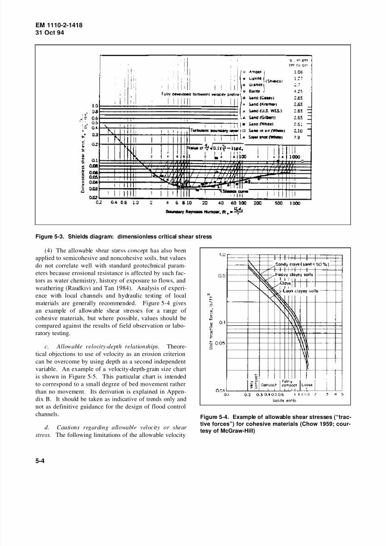
8/14/2019 Channel Stability Assessment for Flood Control Projects
http://slidepdf.com/reader/full/channel-stability-assessment-for-flood-control-projects 63/117

8/14/2019 Channel Stability Assessment for Flood Control Projects
http://slidepdf.com/reader/full/channel-stability-assessment-for-flood-control-projects 64/117

8/14/2019 Channel Stability Assessment for Flood Control Projects
http://slidepdf.com/reader/full/channel-stability-assessment-for-flood-control-projects 65/117

8/14/2019 Channel Stability Assessment for Flood Control Projects
http://slidepdf.com/reader/full/channel-stability-assessment-for-flood-control-projects 66/117
EM 1110-2-141831 Oct 94
(5) Determine the discharge for incipient erosion from
the stage-velocity or discharge-velocity curve, and deter-
mine its frequency from a flood-frequency or flow-
duration curve. This may give some indication of the
potential for instability. For example, if bed movement
has a return period measured in years, which is the case
with some cobble or boulder channels, the potential forextensive profile instability is likely to be negligible. On
the other hand, if the bed is evidently active at relatively
frequent flows, response to channel modifications may be
rapid and extensive.
5-5. Empirical Relationships for Channel
Properties
a. Concepts of channel equilibrium (or regime) and
hydraulic geometry are explained in Section II, Chapter 2.
Empirical relationships expressing the width, depth, and
slope (or velocity) of alluvial channels as separate func-
tions of a dominant or channel-forming discharge weredeveloped by (among others) Lacey (1929-30), Blench
(1957), and Simons and Albertson (1963). References
covering more recent developments, applications, and
criticisms include Hey and Thorne (1986), Stevens and
Nordin (1987), and White (1988). Relationships of this
type may be useful for preliminary or trial selection of
channel properties.
b. In considering flood control channels for a spe-
cific location, it is best to use locally or regionally devel-
oped relationships for hydraulic geometry, for example,
Figure 2-21. If this is not possible, Figures 5-9, 5-10 and
5-11 show tentative relationships that may be useful asrough guides for selecting values of width, depth and
slope, respectively, as functions of channel-forming dis-
charge and bed material. Background on the development
of those charts is provided in Appendix B. The following
guidelines and limitations should be observed:
(1) Where possible, reach-averaged data for existing
channels should be plotted and compared with the indica-
tions of the charts, using bank-full discharge as channel-
forming. If bank-full discharge is not determinable, an
alternative discharge parameter can be used (para-
graph 2-8a). This comparison can indicate how compati-
ble the stream system is with the assumptions of the
charts. The trends of the charts can then be used to esti-
mate changes appropriate for the modified project chan-
nel, particularly for modifications that involve increased
in-channel flows, for example, as a result of close-set
levees or floodwalls.
(2) The charts are likely to be most compatible with
single-channel sand or gravel systems with relatively low
bed material transport. A multichannel system, which
usually indicates higher bed material transport, will tend
to have greater overall widths and slopes but smaller
depths, although individual branches may fit the curves
reasonably in relation to their partial bank-full discharges.
(3) If bed material transport is high, the slopes indi-
cated in Figure 5-11 may be much too low and the depths
in Figure 5-10 may be too high. This is especially true of
channels with sand beds and of ephemeral channels where
much of the flow occurs as flash floods with very high
sediment transport. In perennial-flow gravel rivers with
single channels, slopes are unlikely to be more than three
times greater than those indicated by Figure 5-11. Width
is fairly insensitive to bed material transport unless the
stream is multichanneled or braided. If bed material
transport is high, it is preferable to use a sediment budget
analysis of the type referred to in paragraph 5-7b.
(4) Actively aggrading and degrading channels can
go through a complex cycle of response. In some stages
of the response, they may exhibit large departures from
normal hydraulic geometry relationships. For example, a
channel in the earlier stages of active degradation (inci-
sion) may be abnormally narrow.
(5) The use of all three charts does not permit
explicit selection of roughness and allowable velocity or
shear stress. An alternative hybrid approach involves
determining channel properties using three relation-
ships: the width-discharge relationship of Figure 5-9; theManning formula with a roughness estimate based on
guidelines or experience; and an allowable velocity or
shear stress.
5-6. Analytical Relationships for ChannelProperties
a. Several investigators have proposed that stable
channel dimensions can be calculated analytically by
simultaneous solution of the governing equations. These
methods consider discharge, sediment transport, and bed
material composition as independent variables and width,
depth, and slope as dependant variables. Three equations
are required to solve for the three unknown variables.
Equations for sediment transport and hydraulic resistance
can be chosen, from among several that are available, for
two of the required equations. Chang (1980) proposed
that minimum stream power could be used as the third
5-7

8/14/2019 Channel Stability Assessment for Flood Control Projects
http://slidepdf.com/reader/full/channel-stability-assessment-for-flood-control-projects 67/117

8/14/2019 Channel Stability Assessment for Flood Control Projects
http://slidepdf.com/reader/full/channel-stability-assessment-for-flood-control-projects 68/117

8/14/2019 Channel Stability Assessment for Flood Control Projects
http://slidepdf.com/reader/full/channel-stability-assessment-for-flood-control-projects 69/117
EM 1110-2-141831 Oct 94
Figure 5-11. Tentative guide to slope-discharge relationships for erodible channels. See Appendix B for derivation.
5-7. Sediment Transport and Sediment Budget
a. General.
(1) Many flood control channels have substantial
inflows of bed sediment from upstream and from
tributaries. Stability of channel cross section and profile
then requires not only that the channel should resist ero-
sion, but also that the bed sediment should be transported
through the channel without deposition and loss of
designed hydraulic capacity. If the channel is dimen-
sioned for flood capacity without consideration of sedi-
ment transport continuity, it may undergo deposition until
transport continuity is attained (Figure 5-12).
(2) Most sediment transport functions predict a rate
of sediment transport for given hydraulic conditions,
usually average cross section, slope, and depth of flow. It
5-10

8/14/2019 Channel Stability Assessment for Flood Control Projects
http://slidepdf.com/reader/full/channel-stability-assessment-for-flood-control-projects 70/117
EM 1110-2-141831 Oct 94
Figure 5-12. Infilling of oversized flood control channel
by deposition of sand in floods
is important to know whether a given function is sup-
posed to predict total bed material load or bed load only.For very coarse bed materials, the difference is of little
significance. For sand, the suspended bed material load
may be an order of magnitude greater than the bed load.
(3) It is generally agreed that “blind” computation of
transport without calibration against independent data may
give highly unreliable results. Different sediment trans-
port functions were developed from different sets of field
and laboratory data and are better suited to some applica-
tions than others. Different functions may give widely
differing results for a specified channel. Unfortunately,
acquisition of calibration data is usually very difficult. In
the case of some actively shifting streams, it may bepossible to make a rough check from considerations of
bank erosion and bar deposition (Neill 1984, 1987).
(4) An example where computed bed load transport
was compared with field measurements is shown in Fig-
ure 5-13. Bed load consisted of gravel and coarse sand
and was measured across a gauging section over a period
of several years using a Helley-Smith sampler (Burrows,
Emmett, and Parks 1981). The data, although widely
scattered, are reasonably compatible with the Meyer-Peter
and Muller bed load formula, which is considered applica-
ble to gravel channels (see Vanoni 1975).
(5) A less demanding application of sediment trans-
port functions is to compare the computed transport
capacity of a proposed modified channel with that of the
original channel under a range of equivalent flow condi-
tions, and if possible to match the curves of sediment
transport versus fluid discharge. In this case absolute
accuracy is not so important; however, the transport
function should be selected with some care to ensure that
it is not grossly inapplicable.
(6) In considering channel stability, continuity of
transport over a year or more is generally more important
than in one event lasting a few days or hours. To com-
pute transport over a period of time, a transport rateversus discharge table is normally combined with a flow-
duration table. It is important, however, not to overlook a
large flood event. In some rivers a large flood may trans-
port as much sediment as several years of ordinary flows.
b. Sediment budget analysis. Where field observa-
tions and checks of velocity, shear stress, or hydraulic
geometry indicate a substantial degree of actual or poten-
tial bed instability and sediment transport, a sediment
budget analysis may be conducted for the project reach,
along the lines indicated below.
(1) Bed material transport rates are first estimated asa function of discharge using appropriate transport func-
tions. These rates are then integrated to provide estimated
total loads for two hydrologic conditions: mean annual,
using the long-term flow-duration curve; and design flood,
using the flood hydrograph. Each of those quantities is
computed separately for both existing channel conditions
and proposed project conditions. Where possible, com-
puted loads should be checked against known quantities
of erosion, deposition, or dredging over specific periods
or in specific events. Otherwise, their reliability may be
low.
(2) A sediment balance is then estimated for theproject. The computed loads for existing conditions are
assumed to represent project inflow, and those for project
conditions are assumed to represent project outflow. If
outflow exceeds inflow (either for the mean annual or the
design flood hydrologic condition), bed erosion in the
project channel is indicated. If outflow is less than
inflow, bed deposition is indicated. The differential quan-
tity can be converted to an average depth of erosion or
deposition using the channel dimensions. The actual
erosion or deposition will not, however, be uniform along
the channel, due to slope flattening or steepening.
(3) Procedures for performing the required computa-
tions are included in the computer program “Hydraulic
Design Package for Channels (SAM)” (Thomas et al., in
preparation). General guidance on selection of sediment
transport functions is shown in Table 5-2, and more spe-
cific guidance is included in SAM.
5-11

8/14/2019 Channel Stability Assessment for Flood Control Projects
http://slidepdf.com/reader/full/channel-stability-assessment-for-flood-control-projects 71/117

8/14/2019 Channel Stability Assessment for Flood Control Projects
http://slidepdf.com/reader/full/channel-stability-assessment-for-flood-control-projects 72/117

8/14/2019 Channel Stability Assessment for Flood Control Projects
http://slidepdf.com/reader/full/channel-stability-assessment-for-flood-control-projects 73/117
EM 1110-2-141831 Oct 94
Figure 5-14. Mechanism of bank failure by internal erosion (Hagerty, Spoor, and Kennedy 1986; courtesy of
University of Mississippi)
moderately sinuous rather than straight alignments is
generally preferred, even where there are no existing
constraints on alignment. Geometric guidelines for chan-
nel design are suggested in Figure 5-17.
c. Project changes that tend to alter channel width,
mainly increased channel-forming discharges, tend also to
alter meander dimensions in the course of time. Meander
wavelength, like channel width, is roughly proportional to
the square root of channel-forming discharge. If active
meander shifting exists in the preproject channel, this is
likely to continue after the project is constructed unless
specific measures are taken to arrest meandering. If
velocities and shear stresses are increased by the project,
the rate of shifting is likely to increase.
d . It is generally observed that meander loops tend
to crowd together and increase in amplitude upstream of a
hard point, protected bank, or hydraulic control such as a
river confluence (Figure 5-18). Where only intermittent
bank protection is proposed, progressive distortion of the
meander pattern may occur upstream of each protected
length.
5-10. Basinwide Evaluation for SystemRehabilitation
A systematic approach to stability evaluation, developed
primarily by Vicksburg, the U.S. Army Engineer District,
for rehabilitation of incised streams in hill watersheds of
the Upper Yazoo Basin, Mississippi, involves analysis of
the entire watershed to identify both local and systemwide
instability problems and their interrelationships. Steps in
the process include the following:
a. The entire watershed is investigated in the field
to identify dominant geomorphic processes and features.
(The type of information collected is indicated in
Chapter 4.)
5-14

8/14/2019 Channel Stability Assessment for Flood Control Projects
http://slidepdf.com/reader/full/channel-stability-assessment-for-flood-control-projects 74/117
EM 1110-2-141831 Oct 94
Figure 5-15. Stability analysis for steep cohesive river banks (Thorne and Osman 1988; courtesy of American
Society of Civil Engineers)
Figure 5-16. Meander geometry (after Nunnally and
Shields 1985)
b. Using the information collected, an assessment is
made of the system dynamics. Channels are classed as
degradational, aggradational, or in equilibrium. Banks are
classed as stable or unstable.
c. Hydraulic and geotechnical stability parameters
are defined for reaches assessed to be stable. Generally,hydraulic parameters refer to the channel bed, for exam-
ple, stable slope, boundary shear stress, or sediment trans-
port parameters derived from modeling. Geotechnical
parameters refer to the banks; they include stable bank
height and angle or more complex parameters derived
from detailed geotechnical analyses. For generalizing and
transferring values between reaches, parameter values can
be correlated with drainage area or discharge. If the
watershed has subareas with different land use or geologic
conditions, sets of stability parameter values may be
required for each subarea.
d . Each more or less homogeneous reach of chan-
nel in the watershed is compared against the developed
stability parameters and confirmed as stable, degrada-
tional, or aggradational. Additional considerations, such
as the long-term effects of existing stabilization structures
and anticipated changes in land use, may form part of the
assessment. Anomalies within a specific reach may
require further investigation.
5-15

8/14/2019 Channel Stability Assessment for Flood Control Projects
http://slidepdf.com/reader/full/channel-stability-assessment-for-flood-control-projects 75/117
EM 1110-2-141831 Oct 94
Figure 5-17. Suggested relationship between bank-full (channel-forming) discharge and meander wavelength for
layout of new channel (After Ackers and Charlton 1970; courtesy of Journal of Hydrology )
Figure 5-18. Distortion of meander pattern upstream of
protected length
e. Rehabilitation measures are designed for unstable
parts of the watershed and channel system. (The design
of rehabilitation measures is discussed in Chapter 6.)
5-11. General Stepwise Approach
Whether or not an entire watershed needs to be evaluated,
a systematic approach to evaluating and documenting the
stability characteristics of the area relevant to a flood
control channel project is recommended. The following
sequence of steps may be found appropriate:
a. Describe characteristics of the area contributing
to or affected by the project and its channel system.
b. Identify and assess existing instabilities.
c. I de nt ify p ro je ct fe at ure s with s tab ili ty
implications.
d . Analyze stability parameters for the existing
channel.
e. Evaluate and analyze potential stability problems
with the completed project, and consider preventive or
mitigative measures or project changes.
f . Summarize conclusions and recommendations.
5-12. Checklist of Items to Consider
The following checklist summarizes items that may be
considered in a systematic stability evaluation. At each
step, the investigator should consider the potentially vul-
nerable aspects of the system and the possibilities for
5-16

8/14/2019 Channel Stability Assessment for Flood Control Projects
http://slidepdf.com/reader/full/channel-stability-assessment-for-flood-control-projects 76/117

8/14/2019 Channel Stability Assessment for Flood Control Projects
http://slidepdf.com/reader/full/channel-stability-assessment-for-flood-control-projects 77/117

8/14/2019 Channel Stability Assessment for Flood Control Projects
http://slidepdf.com/reader/full/channel-stability-assessment-for-flood-control-projects 78/117
EM 1110-2-141831 Oct 94
(e) Sediment sources: surface erosion from recent
logging in upper basin, high bank erosion in some tribu-
tary hill streams.
(3) Channel system.
(a) Upstream of project, main stem and tributaries aremostly incised with occasional bedrock outcrops. Some
tributaries deliver quantities of fine and coarse sediment.
No storage reservoirs. Minor irrigation diversion with
weir just upstream of project length.
(b) In project length, Flatfish River flows in broad
alluvial valley through mixed farmland and residential
acreages. Channel partly single and partly double with
islands. Floodplain both sides except at occasional points
of impingement on valley margins. Probably underlain by
considerable depths of alluvium in most areas.
(c) Downstream of project length, Flatfish graduallychanges to a meandering sand river, and discharges into a
larger river 20 miles downstream. There are only a few
minor tributaries.
(4) Flood hydrology: no hydrometric data or simula-
tion studies are available for Flatfish River. Regional
correlations suggest mean annual flood around 1,200 cfs
and 50-year flood around 3,500 cfs. Largest known flood
occurred in 1962 and most recent overbank flood in 1988.
1962 flood caused $10 million damage to crops and
buildings, and 1988 flood $20 million mainly to resi-
dences. Extensive residential development occurred
between 1962 and 1988.
(5) Project length of river.
(a) Planform. Irregular meanders with splitting
around islands. Meanders typically about 1,000-ft wave-
length by about 500-ft full-wave amplitude. Comparison
of 1984 and 1950 aerial photos indicates substantial chan-
nel migration, and trend to wider channel with more
exposed bars.
(b) Profile. Average slope 8 ft per mile. Sequence
of pools and riffles at low flow. No visible rock rapids or
nick zones. Narrow bridge at lower end may cause back-
water effect at high flows.
(c) Cross sections. Typical bank-full section (in
single-channel reach) about 70 by 4 ft, but considerable
variability. Summed width of double reaches about
100 ft. Summed floodplain width (both sides) 500 to
1,500 ft. Floodplain cover about 40% grass, 30% crops,
30% trees. Overbank flow about once every 2 years,
allegedly more frequent than in past. No existing flood
protection dikes.
(d) Boundary materials. Bed: sand and gravel up to
50 mm. Channel bars variable in form and in surface
grain sizes. Banks stratified: 1 to 2 ft overbank silt andfine sand overlying medium sand and gravel. Banks
mostly cleared of vegetation except through wooded
floodplain areas. Some local bank protection of limited
effectiveness using timber piles and car bodies. Some
complaints of accelerated erosion due to protection of
neighboring properties.
(e) Miscellaneous observations. Water is clear in
low flow, turbid in floods. Gravel moves actively on bars
under moderate flows. Log debris on some bars and
islands. Alleged adverse effects from logging in upper
basin. Some winter ice but no effects on channel
stability. No significant boat traffic. No local floodcontrol on similar streams.
b. Existing instabilities.
(1) Drainage basin. Basin land use changes may
have somewhat increased flood peaks, sediment loads, and
debris. An apparent trend of increasing channel instability
may continue. There are no plans for controlling basin
erosion, which is not considered a major problem.
(2) Channel system. Outside the project area, it has
not been examined in detail. Superficially there appear to
be no major upstream instabilities. Any change in sedi-ment deliveries to downstream reaches would be of con-
cern to fishery authorities.
(3) Project channel. Substantial lateral instability:
eroding banks, loss of land, mobile channel bars. Aerial
photos suggest bank recession rates up to 5 ft per year,
residents allege even higher local rates. A supply of
coarse sediment enters the length from upstream. No
evidence of profile instability: bridge foundations near
either end show no indication of degradation or
aggradation. Some apparent increase in average width
since 1950 aerial photos. Only isolated local attempts to
control bank erosion.
c. Analysis of stability parameters. This step is
omitted in this qualitative evaluation. See quantitative
examples in Appendix C.
d. Stability implications of project features. The
proposal is to construct levees on both sides of the
5-19

8/14/2019 Channel Stability Assessment for Flood Control Projects
http://slidepdf.com/reader/full/channel-stability-assessment-for-flood-control-projects 79/117
EM 1110-2-141831 Oct 94
channel, to contain floods up to the 50-year level.
Riparian owners would like the levees to be close to the
riverbanks and assume that there would also be bank
protection. Project details have not been determined.
e. Assessment of potential stability problems with
proposed project .
(1) Altered flood hydrology. Levees close to the
river would probably increase flood peaks to some degree
because of the deregulating effect of eliminating flood-
plain storage. This effect can be reduced if the levees are
set back. Surveys and hydrologic/hydraulic analyses
would be required to examine these effects.
(2) Lateral instability. Existing lateral instability
poses problems for close-set levees. Substantial setback
is indicated to avoid excessive bank protection costs.
Increased in-channel flow peaks may tend to increase
lateral instability and sediment supply to downstream.Erosion protection of river banks or levee faces may be
required at least locally.
(3) Profile instability. Some flattening of slope may
be expected because of increased in-channel flood peaks,
but process is likely to be slow and controlled by armor-
ing of bed material. Grade controls could be installed at
a later stage if a problem develops.
(4) Cross-sectional instability. There may be a ten-
dency for cross sections to widen and possibly deepen
eventually, because of increased in-channel flood peaks.
This is unlikely to be of serious concern under present
development.
f. Summary.
(1) A workable scheme for 50-year flood protection
can be developed. The existing channel is laterally unsta-
ble and is liable to encroach on levees located near the
channel. Because it eliminates much floodplain storage
and increases in-channel flood peaks, the project may
aggravate meander shifting and alter channel properties
somewhat. Potential maintenance problems include bank
protection to secure the levees and increased delivery of
sediment to downstream reaches.
(2) Further studies should consider a range of solu-
tions to the flooding problem. Any solution involvinglevees should recognize the effects of existing and possi-
bly enhanced instability on the security of the levee sys-
tem, and should provide for adequate protection against
erosion or undermining.
5-20

8/14/2019 Channel Stability Assessment for Flood Control Projects
http://slidepdf.com/reader/full/channel-stability-assessment-for-flood-control-projects 80/117
EM 1110-2-141831 Oct 94
Chapter 6Practical Aspects of Stability Design
6-1. General
This chapter provides guidance and examples for variouspractical aspects of design for stability. The main causes
of the type of instability to be controlled are reviewed
briefly in each case. General principles of channel equi-
librium and response are reviewed in Chapter 2. Stability
problems with flood control channels are discussed in
detail in Chapter 3.
6-2. Ranking of Flood Control Methods
From the viewpoint of minimizing channel stability prob-
lems, methods of flood control can be generally ranked in
the following order of acceptability:
a. Nonstructural flood control measures such as
floodproofing, evacuation, and flood warning systems.
b. Levees set back clear of the meander belt.
c. Levees within the meander belt.
d . Off-channel detention basins.
e. Upstream flood retention or detention structures.
f . Flood bypass channel.
g. Clearing and snagging (reduced roughness).
h. Enlarged compound cross section with existing
low-flow channel left intact. (The low-flow channel
carries average dry-season flow.)
i. Channel widening with or without levees.
j. Channel deepening with or without levees.
From a safety viewpoint, on the other hand, channeliza-
tion measures like h and i above tend to be more defensi-ble than structural measures such as b, c, and e. Potential
conflicts between stability and safety requirements should
be discussed with local interests and considered together
with economic, social, and environmental factors.
Table 6-1 shows the potential for several flood protection
measures to cause instabilities in various types of river
channels.
6-3. Alignment and Planform
Earlier flood control projects often involved extensive
realignment of pre-existing streams and channels. Sinu-
ous or meandering channels were straightened to improve
hydraulic conveyance or to eliminate eroding bends, often
without sufficient consideration of potential effects onlong-term stability. Severe instability in profile and cross
section often occurred in and beyond the project length,
and the treated length of channel often reverted eventually
to a meandering state unless expensive remedial measures
were undertaken (Figure 3-6).
6-4. Single-Channel Streams
a. Most existing channels are sinuous to some
degree. Current practice is generally to retain existing
alignments where practicable. Even where an entirely
new channel is to be constructed, arguments can be made
for a sinuous rather than a straight alignment. Keller andBrookes (1984) state “Consideration of meandering in
channelization projects should be encouraged wherever
feasible because meandering channels often have a more
consistent pattern of sediment routing, are morphologi-
cally more stable, have more hydrological and biological
diversity, and aesthetically are more pleasing.” Similar
comments are made by Nunnally and Shields (1985).
Flood control channels stabilized on meandering align-
ments are shown in Figures 6-1 and 6-2. Points that can
be made in support of sinuous alignments include the
following:
(1) Retention of a sinuous alignment avoids prob-lems of excessive slope associated with straightening.
(2) Straight channels transporting bed material tend
to form alternating side bars that induce submeandering in
the low-flow channel (see Figure 3-2). This may even-
tually lead to resumption of full-scale meandering.
(3) Sinuous channels have greater local variability of
depth, velocity, and cross-sectional shape, which is attrac-
tive for fish habitat.
b. Where a sinuous alignment is retained, however,
it may be appropriate to eliminate or improve severe
bends that are subject to rapid bank erosion and flow
disturbances (Figure 6-3). Where the channel is widened
by side cuts on alternating sides, the sinuosity can thereby
be reduced to some degree (see Figure 3-3).
6-1

8/14/2019 Channel Stability Assessment for Flood Control Projects
http://slidepdf.com/reader/full/channel-stability-assessment-for-flood-control-projects 81/117
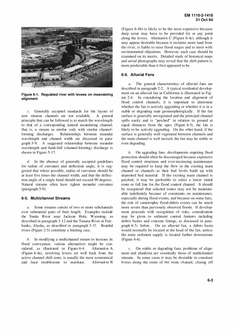
8/14/2019 Channel Stability Assessment for Flood Control Projects
http://slidepdf.com/reader/full/channel-stability-assessment-for-flood-control-projects 82/117
EM 1110-2-141831 Oct 94
Figure 6-1. Regulated river with levees on meandering
alignment
c. Generally accepted standards for the layout of
new sinuous channels are not available. A generalprinciple that can be followed is to match the wavelength
to that of a corresponding natural meandering channel,
that is, a stream in similar soils with similar channel-
forming discharges. Relationships between meander
wavelength and channel width are discussed in para-
graph 5-9. A suggested relationship between meander
wavelength and bank-full (channel-forming) discharge is
shown in Figure 5-17.
d . In the absence of generally accepted guidelines
for radius of curvature and deflection angle, it is sug-
gested that where possible, radius of curvature should be
at least five times the channel width, and that the deflec-tion angle of a single bend should not exceed 90 degrees.
Natural streams often have tighter meander curvature
(paragraph 5-9).
6-5. Multichannel Streams
a. Some streams consist of two or more subchannels
over substantial parts of their length. Examples include
the Snake River near Jackson Hole, Wyoming, as
described in paragraph 3-12 and the Tanana River at Fair-
banks, Alaska, as described in paragraph 3-17. Braided
rivers (Figure 2-5) constitute a limiting case.
b. In modifying a multichannel stream to increase its
flood conveyance, various alternatives might be con-
sidered, as illustrated in Figure 6-4. Alternative A
(Figure 6-4a), involving levees set well back from the
active channel shift zone, is usually the most economical
and least troublesome to maintain. Alternative B
(Figure 6-4b) is likely to be the most expensive because
deep scour may have to be provided for at any point
along the levees. Alternative C (Figure 6-4c), although it
may appear desirable because it reclaims more land from
the river, is liable to raise flood stages and to meet with
environmental objections. However, each case should be
examined on its merits. Detailed study of historical mapsand aerial photographs may reveal that the shift pattern is
more predictable than it first appeared to be.
6-6. Alluvial Fans
a. The general characteristics of alluvial fans are
described in paragraph 2-2. A typical residential develop-
ment on an alluvial fan in California is illustrated in Fig-
ure 2-4. In considering the location and alignment of
flood control channels, it is important to determine
whether the fan is actively aggrading or whether it is in a
stable or degrading state geomorphologically. If the fan
surface is generally unvegetated and the principal channelspills easily and is “perched” in relation to ground at
equal distances from the apex (Figure 6-5), the fan is
likely to be actively aggrading. On the other hand, if the
surface is generally well vegetated between channels and
the main channel is well incised, the fan may be stable or
even degrading.
b. On aggrading fans, developments requiring flood
protection should often be discouraged because expensive
flood control structures and ever-increasing maintenance
may be required to keep the flow in the existing main
channel or channels as their bed levels build up with
deposited bed material. If the existing main channel isperched, it may be preferable to select a lower initial
route or fall line for the flood control channel. It should
be recognized that selected routes may not be maintain-
able indefinitely because of constraints on maintenance,
especially during flood events, and because on some fans,
the risk of catastrophic flood-debris events can be much
more severe than previously observed floods. If develop-
ment proceeds with recognition of risks, consideration
may be given to sediment control features including
debris basins and concrete linings, as discussed in para-
graph 6-7c below. On an alluvial fan, a debris basin
would normally be located at the head of the fan, unless
the main sediment supply is located farther downstream
(Figure 6-6).
c. On stable or degrading fans, problems of align-
ment and planform are essentially those of multichannel
streams. In some cases it may be desirable to construct
levees along the route of the main channel, closing off
6-3

8/14/2019 Channel Stability Assessment for Flood Control Projects
http://slidepdf.com/reader/full/channel-stability-assessment-for-flood-control-projects 83/117
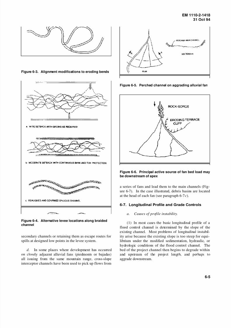
8/14/2019 Channel Stability Assessment for Flood Control Projects
http://slidepdf.com/reader/full/channel-stability-assessment-for-flood-control-projects 84/117
EM 1110-2-141831 Oct 94
Figure 6-3. Alignment modifications to eroding bends
Figure 6-4. Alternative levee locations along braided
channel
secondary channels or retaining them as escape routes for
spills at designed low points in the levee system.
d . In some places where development has occurred
on closely adjacent alluvial fans (piedmonts or bajadas)
all issuing from the same mountain range, cross-slope
interceptor channels have been used to pick up flows from
Figure 6-5. Perched channel on aggrading alluvial fan
Figure 6-6. Principal active source of fan bed load maybe downstream of apex
a series of fans and lead them to the main channels (Fig-
ure 6-7). In the case illustrated, debris basins are located
at the head of each fan (see paragraph 6-7c).
6-7. Longitudinal Profile and Grade Controls
a. Causes of profile instability.
(1) In most cases the basic longitudinal profile of a
flood control channel is determined by the slope of the
existing channel. Most problems of longitudinal instabil-
ity arise because the existing slope is too steep for equi-
librium under the modified sedimentation, hydraulic, or
hydrologic conditions of the flood control channel. The
bed of the project channel then begins to degrade within
and upstream of the project length, and perhaps to
aggrade downstream.
6-5

8/14/2019 Channel Stability Assessment for Flood Control Projects
http://slidepdf.com/reader/full/channel-stability-assessment-for-flood-control-projects 85/117
EM 1110-2-141831 Oct 94
Figure 6-7. Cross-slope interceptor channels collecting flood flows from adjacent alluvial fans
(2) There are two main reasons the existing gradient
may be too steep for the project channel. The first reason
is that discharges in the project channel may be signifi-
cantly larger than in the existing channel. As explained in
Chapter 2, larger discharges require flatter slopes to main-
tain equilibrium with equivalent bed material transport;
see also Figure 5-11. A second reason is shortening
through realignment, which was a common problem in
earlier flood control projects but is now discouraged, as
discussed in paragraph 6-4. A third, less common reason
may be the addition of a basin or reservoir that traps bed
material upstream of the project channel (paragraph 6-6).
(3) Problems of profile degradation are most common
and severe in channels with beds of sand or other easily
eroded fine-grained materials. Examples include many of
the bluff-line streams of northern Mississippi, which as a
result of land-use changes and channel alterations are
generally degrading into fine-grained deposits of sand,
loess, silt, and clay. In gravel-bed channels, the ability of
the stream to armor the surface of the bed with the
coarser fraction of the bed load tends to retard rates of
degradation.
(4) An opposite type of longitudinal stability prob-
lem arises when the project channel slope is too flat and
begins to steepen (aggrade) by accumulation of bed mate-
rial. This can occur in diversion and bypass projects if
flows in the existing channel are thereby reduced but the
channel continues to take a substantial part of the bed
material load (see also Chapter 3, Section I). This type of
problem may also arise in new channel projects if the
slope provided is insufficient to transport all the inflowing
bed material.
6-6

8/14/2019 Channel Stability Assessment for Flood Control Projects
http://slidepdf.com/reader/full/channel-stability-assessment-for-flood-control-projects 86/117

8/14/2019 Channel Stability Assessment for Flood Control Projects
http://slidepdf.com/reader/full/channel-stability-assessment-for-flood-control-projects 87/117

8/14/2019 Channel Stability Assessment for Flood Control Projects
http://slidepdf.com/reader/full/channel-stability-assessment-for-flood-control-projects 88/117

8/14/2019 Channel Stability Assessment for Flood Control Projects
http://slidepdf.com/reader/full/channel-stability-assessment-for-flood-control-projects 89/117
EM 1110-2-141831 Oct 94
Figure 6-12. Flume-type grade control/gauging
structure
Figure 6-13. Drop structure with energy dissipator
Figure 6-14. Debris basin and dam at head of alluvial
fan
(5) Channel deepened and widened to part depth
(with berm).
(6) Major enlargement with retention of inner low-
flow channel (Figure 6-18).
(7) Existing channel paralleled by separate floodwayor bypass channel.
b. A number of these alternatives are also discussed
in paragraphs 3-1 and 6-2. From a stability viewpoint
Type a is generally preferable, but in many cases other
considerations will predominate. Type g is also attractive
if sedimentation is not a problem (paragraph 3-7). Gener-
ally, widened and deepened sections are the most
susceptible to problems of bank erosion, channel shifting,
and profile degradation.
c. A wide variety of practices exist for determining
channel capacity and frequency of the bank-full condition,depending on the overall requirements of the project. In
compound cross sections such as type e, the berm level
normally corresponds to the annual summer flood. In
type f , the low-flow channel may be sized for dry-season
flows only.
d. Increasing channel capacity in environmentally
sensitive areas.
(1) A problem facing many Corps Districts is design
of flood control projects in river basins or specific reaches
of river basins that are extremely environmentally sensi-
tive. Increased channel conveyance can often be achievedin these areas through either clearing and snagging or
channel cleanout alternatives. These alternative channel
improvement methods, both of which are generally much
less destructive to the environment than conventional
channel enlargement, are defined in (2) and (3) below.
(See also paragraphs 3-2 and 3-3.)
(2) Clearing and snagging. Channel clearing and
snagging (Figure 6-19) involves the removal of trees,
brush, logjams, and other material from the channel.
Channel capacity is increased as roughness is reduced and
blockages removed. Work is typically limited to within
the top bank of the channel but may be extended to the
overbank if significant overbank flow occurs and the work
is environmentally acceptable. The degree of improve-
ment can range from total clearing where all woody vege-
tation is removed from the channel to selective clearing
6-10

8/14/2019 Channel Stability Assessment for Flood Control Projects
http://slidepdf.com/reader/full/channel-stability-assessment-for-flood-control-projects 90/117
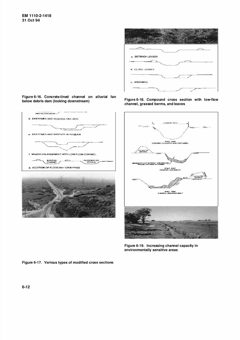
8/14/2019 Channel Stability Assessment for Flood Control Projects
http://slidepdf.com/reader/full/channel-stability-assessment-for-flood-control-projects 91/117
EM 1110-2-141831 Oct 94
Figure 6-16. Concrete-lined channel on alluvial fan
below debris dam (looking downstream)
Figure 6-17. Various types of modified cross sections
Figure 6-18. Compound cross section with low-flow
channel, grassed berms, and leaves
Figure 6-19. Increasing channel capacity in
environmentally sensitive areas
6-12
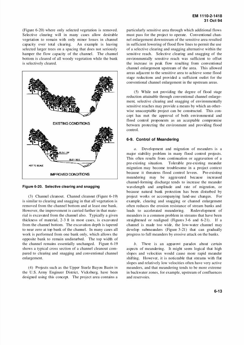
8/14/2019 Channel Stability Assessment for Flood Control Projects
http://slidepdf.com/reader/full/channel-stability-assessment-for-flood-control-projects 92/117
EM 1110-2-141831 Oct 94
(Figure 6-20) where only selected vegetation is removed.
Selective clearing will in many cases allow desirable
vegetation to remain with only minor losses in channel
capacity over total clearing. An example is leaving
selected larger trees on a spacing that does not seriously
hamper the flow capacity of the channel. The channel
bottom is cleared of all woody vegetation while the bank is selectively cleared.
Figure 6-20. Selective clearing and snagging
(3) Channel cleanout. Channel cleanout (Figure 6-19)
is similar to clearing and snagging in that all vegetation is
removed from the channel bottom and at least one bank.
However, the improvement is carried farther in that mate-
rial is excavated from the channel also. Typically a given
thickness of material, 2-3 ft in most cases, is excavated
from the channel bottom. The excavation depth is tapered
to near zero at top bank of the channel. In many cases all
work is performed from one bank only, which allows the
opposite bank to remain undisturbed. The top width of
the channel remains essentially unchanged. Figure 6-19
shows a typical cross section of a channel cleanout com-
pared to clearing and snagging and conventional channel
enlargement.
(4) Projects such as the Upper Steele Bayou Basin in
the U.S. Army Engineer District, Vicksburg, have been
designed using this concept. The project area contains a
particularly sensitive area through which additional flows
must pass for the project to operate. Conventional chan-
nel enlargement downstream of the sensitive area resulted
in sufficient lowering of flood flow lines to permit the use
of a selective clearing and snagging alternative within the
sensitive reach. Selective clearing and snagging of the
environmentally sensitive reach was sufficient to offsetthe increase in peak flow resulting from conventional
channel enlargement upstream of the area. This allowed
areas adjacent to the sensitive area to achieve some flood
stage reductions and provided a sufficient outlet for the
conventional channel enlargement in the upstream areas.
(5) While not providing the degree of flood stage
reduction attainable through conventional channel enlarge-
ment, selective clearing and snagging of environmentally
sensitive reaches may provide a means by which an other-
wise unacceptable project can be constructed. This con-
cept has met the approval of both environmental and
flood control proponents as an acceptable compromisebetween protecting the environment and providing flood
control.
6-9. Control of Meandering
a. Development and migration of meanders is a
major stability problem in many flood control projects.
This often results from continuation or aggravation of a
pre-existing situation. Tolerable pre-existing meander
migration may become troublesome in a project context
because it threatens flood control levees. Pre-existing
meandering may be aggravated because increased
channel-forming discharge tends to increase the meanderwavelength and amplitude and rate of migration, or
because natural bank protection has been disturbed by
project works or accompanying land-use changes. For
example, clearing and snagging or channel enlargement
often reduces the erosion resistance of stream banks and
leads to accelerated meandering. Redevelopment of
meanders is a common problem in streams that have been
straightened or realigned (Figures 3-6 and 6-21). If a
channel is made too wide, the low-water channel may
develop submeanders (Figure 3-21) that can gradually
progress to full meanders by erosive attack on the banks.
b. There is an apparent paradox about certain
aspects of meandering. It might seem logical that high
slopes and velocities would cause more rapid meander
shifting. However, it is noticeable that streams with flat
slopes and relatively low velocities often have very active
meanders, and that meandering tends to be more extreme
in backwater zones, for example, upstream of confluences
and reservoirs.
6-13

8/14/2019 Channel Stability Assessment for Flood Control Projects
http://slidepdf.com/reader/full/channel-stability-assessment-for-flood-control-projects 93/117
EM 1110-2-141831 Oct 94
Figure 6-21. Redevelopment of meanders in straight-
ened channel following side bar development
c. Several points about dealing with meandering in
project design and maintenance are discussed in (11-(5))
below.
(1) The best solution is to locate levees outside the
meander belt. This is not always possible, however. Insome cases the meander belt may occupy the entire valley
bottom. In other cases the meander belt may widen after
construction due to factors mentioned in a above. Some-
times the pattern of future meander shifting is difficult to
predict.
(2) Levees can be set back as far as possible from the
existing channel, and a minimum distance between the
levees and eroding riverbanks can be specified, with an
understanding that protection works will be initiated when
this minimum is reached at any point. In the case of the
Tanana River at Fairbanks, Alaska, a deferred construc-
tion agreement provides for construction of groins when
the specified minimum setback is encroached upon.
(3) Short lengths of bank revetment at points of
active river attack are not usually effective in the long
term. The attack usually shifts to other points and tends
to outflank the short revetments. As these are extended,
the end result is protection of the entire project length.
(4) An intermittent form of bank protection, such as
groins, is usually more economical than continuous revet-
ment. Although groins tend to cause flow disturbances
that are sometimes unacceptable for navigational reasons,
they appear to be beneficial to fisheries because they
provide diversity of flow depths and shelter zones of low
velocity during high flows.
(5) Bank vegetation and root systems provide effec-
tive protection against rapid meander shifting in many
natural streams. Vegetation should not be disturbed
unless there is no reasonable alternative. In the case of
channel enlargement, excavation on the inner bank only
(see Figure 3-3) enables retention of protective vegetation
on outer banks. Where existing vegetation has to be
removed, it may be feasible to replant. However, biolog-
ical restorative techniques that are successful in small
streams are not always transferable to larger channels.
EM 1110-2-1205 should be consulted for guidance.
6-10. Bank Protection
a. Artificial bank protection is used to control
meandering, to protect channel banks and levees against
velocities and shear stresses that are too high for the bank
materials, or to prevent toe scour and removal of berms
that would encourage progressive bank failure due to geo-
technical factors such as gravity slumping and seepage
(Figure 6-22).
Figure 6-22. Revetment necessitated by encroachment
of bank caving on levee
b. Only general comments on bank protection are
made herein. More extensive information is given in
Petersen (1986), and riprap bank protection is covered in
EM 1110-2-1601. EM 1110-2-1205 discusses various
6-14

8/14/2019 Channel Stability Assessment for Flood Control Projects
http://slidepdf.com/reader/full/channel-stability-assessment-for-flood-control-projects 94/117
EM 1110-2-141831 Oct 94
methods from an environmental viewpoint. Ports (1989)
discusses various aspects of bank erosion and protection.
c. Methods of bank protection can be divided into
continuous types such as revetment and discontinuous
types such as groins (Figure 6-23). Materials include
rock riprap, natural or planted vegetation, concrete, andfabricated or patented systems.
Figure 6-23. Combined use of continuous toe protec-
tion and intermittent groins
d. Failure of riprap bank protection is often due to
underscouring at the toe. Galay, Yaremko, and Quazi
(1987) give a detailed discussion of riprap protection in
relation to toe scour. EM 1110-2-1601 provides guidance
on weighed toe construction details.
e. In meandering streams, bank protection is usually
provided initially only on the outer banks. The protection
should be extended far enough upstream and downstream
to avoid outflanking (Figure 6-24).
6-11. Control of Sediment Deposition
a. Loss of designed flood conveyance by sediment
deposition is a common problem. It often occurs as a
result of longitudinal instability (see paragraphs 6-3
through 6-6), or as a result of enlargements that reduce
the capacity of the channel to transport sediment arriving
from upstream through the project length. Flood
Figure 6-24. Extension of outer bank protection
downstream of inflection points
diversions, high-level bypasses, or offstream detention
reservoirs may also reduce the sediment transport capacity
of the main channel. Deposition may occur in unmodified
channel reaches downstream from the project because of
increased sediment delivery from bank erosion or bed
degradation within the project length.
b. Most commonly, deposition is a problem of sandy materials deposited from bed load or suspended
load or both. Deposition of fine sand and silt from sus-
pended load may be a problem on berms and in slack-
water areas, as well as in estuarial and deltaic channels.
Loss of conveyance due to deposition of gravel is less
common generally, but is a special problem with alluvial
fans in hilly terrain (see paragraph 6-6). Alteration of the
nature and location of sediment deposits due to upstream
works may adversely affect fish habitat in gravel-bed
rivers (Milhous 1982).
c. Methods of controlling sedimentation include the
following:
(1) Design of flood control channels that are capable
of properly conveying the postproject sediment loads that
will be imposed on the system.
(2) Debris basin at the upstream end of project,
designed to capture part of the bed material load. It must
be evacuated periodically. See EM 1110-2-1601 for
details.
(3) Sediment retention structures, grade control
structures, etc., in the headwaters and tributaries.
(4) Soil conservation measures in the watershed,
including legislation to control sediment production from
land use and developments.
(5) Periodic excavation or dredging of the project
channel. It is necessary to ensure that a single flood
6-15

8/14/2019 Channel Stability Assessment for Flood Control Projects
http://slidepdf.com/reader/full/channel-stability-assessment-for-flood-control-projects 95/117

8/14/2019 Channel Stability Assessment for Flood Control Projects
http://slidepdf.com/reader/full/channel-stability-assessment-for-flood-control-projects 96/117

8/14/2019 Channel Stability Assessment for Flood Control Projects
http://slidepdf.com/reader/full/channel-stability-assessment-for-flood-control-projects 97/117
EM 1110-2-141831 Oct 94
Chow 1959
Chow, V. T. 1959. Open-Channel Hydraulics, McGraw-
Hill, New York.
Colby 1964a
Colby, B. R. 1964a. “Discharge of Sands and Mean-
v el oc it y Rel at io ns hi ps i n San d- be d Str ea ms ,”U.S. Geological Survey Professional Paper 462-A,
U.S. Government Printing Office, Washington, DC.
Colby 1964b
Colby, B. R. 1964b. “Practical Computation of Bed
Material Discharge,” Journal of the Hydraulics Division,
American Society of Civil Engineers, Vol 90, No. HY2,
pp 217-246.
Copeland and Thomas 1989
Copeland, R. R., and Thomas, W. A. 1989. “Corte
Madera Creek Sedimentation Study; Numerical Model
Investigation,” Technical Report HL-89-6, U.S. ArmyEngineer Waterways Experiment Station, Vicksburg, MS.
Cornell University 1952
Cornell University. 1952. “Waterlaid Materials,”
Airphoto Analysis, Vol 4, Prepared for Office of Naval
Research, Arlington, VA, by Cornell University,
Ithaca, NY.
Diplas and Sutherland 1988
Diplas, P., and Sutherland, A. J. 1988. “Sampling Tech-
niques for Gravel Sized Sediments,” Journal of Hydraulic
Engineering, American Society of Civil Engineers,
Vol 114, No. 5, pp 484-501.
Einstein 1950
Einstein, Hans A. 1950. “The Bed Load Function for
Sediment Transportation in Open Channels,” Technical
Bulletin No. 1026, U.S. Department of Agriculture, Soil
Conservation Service, Washington, DC.
Elliott 1984
Elliott, Charles M., ed. 1984. River Meandering: Pro-
ceedings of the Conference Rivers ’83, New Orleans, LA,
October 24-26, 1983, American Society of Civil Engi-
neers, New York.
Ferguson 1984
Ferguson, R. I. 1984. “The Threshold Between Mean-
dering and Braiding,” Channels and Channel Control
Structures, Proceedings of the 1st International
Conference on Hydraulic Design in Water Resources
Engineering, University of Southampton, April 1984,
K. V. H. Smith, ed., Springer-Verlag, New York, pp 6-15
to 6-30.
Galay 1983
Galay, V. J. 1983. “Causes of River Bed Degradation,”Water Resources Research, Vol 19, No. 5, pp 1057-1090.
Galay, Yaremko, and Quazi 1987
Galay, V. J., Yaremko, E. K., and Quazi, B. 1987.
“River Bed Scour and Construction of Stone Riprap Pro-
tection,” Sediment Transport in Gravel-bed Rivers,
C. R. Thorne, J. C. Bathurst, R. D. Hey, ed., Wiley, New
York, pp 353-383.
Gatto 1984
Gatto, L. W. 1984. “Tanana River Monitoring and
Research Program: Relationships among Bank Recession,
Vegetation, Soils, Sediments and Permafrost on theTanana River near Fairbanks, Alaska,” Special
Report 84-21, Prepared for U.S. Army Engineer District,
Alaska, Anchorage, by U.S. Army Cold Regions Research
and Engineering Laboratory, Hanover, NH.
Graf 1984
Graf, W. H. 1984. Hydraulics of Sediment Transport,
McGraw-Hill, New York.
Gregory 1984
Gregory, D. I. 1984. “Response of a Meandering River
to Artificial Modification,” River Meandering: Proceed-
ings of the Conference Rivers ’83, New Orleans, LA,October 24-26, 1983, Charles M. Elliott, ed., American
Society of Civil Engineers, New York, pp 398-409.
Hagerty 1992
Hagerty, D. J. 1992. “Identification of Piping and Sap-
ping Erosion of Streambanks,” Contract Report HL-92-1,
Prepared by University of Louisville, Louisville, KY, for
U.S. Army Engineer Waterways Experiment Station,
Vicksburg, MS.
Hagerty, Spoor, and Kennedy 1986
Hagerty, D. J., Spoor, M. F., and Kennedy, J. F. 1986.
“Interactive Mechanisms of Alluvial-Stream Bank Ero-
sion,” River Sedimentation, Vol III, Proceedings of the
Third International Symposium of River Sedimentation,
S. Y. Wang, H. W. Shen, and L. Z. Ding, ed., University
of Mississippi, University, MS, pp 1160-1168.
A-2

8/14/2019 Channel Stability Assessment for Flood Control Projects
http://slidepdf.com/reader/full/channel-stability-assessment-for-flood-control-projects 98/117
EM 1110-2-141831 Oct 94
Hey 1984
Hey, R. D. 1984. “Plan Geometry of River Meanders,”
River Meandering: Proceedings of the Conference
Rivers ’83, New Orleans, LA, October 24-26, 1983,
Charles M. Elliott, ed., American Society of Civil Engi-
neers, New York, pp 30-43.
Hey and Thorne 1983
Hey, R. D., and Thorne, C. R. 1983. “Accuracy of Sur-
face Samples from Gravel Bed Material,” Journal of
Hydraulic Engineering, American Society of Civil Engi-
neers, Vol 109, No. 6, pp 842-851.
Hey and Thorne 1986
Hey, R. D., and Thorne, C. R. 1986. “Stable Channels
with Mobile Gravel Beds,” Journal of Hydraulic Engi-
neering, American Society of Civil Engineers, Vol 112,
No. 8, pp 671-689.
Hey, Bathurst, and Thorne 1982Hey, R. D., Bathurst, J. C., and Thorne, C. R., ed. 1982.
Gravel-Bed Rivers: Fluvial Processes, Engineering, and
Management, Wiley, New York.
Jansen, van Bendegom, van den Berg, de Vries and
Zanen 1979
Jansen, P. Ph., van Bendegom, L., van den Berg, J.,
de Vries, M., and Zanen, A. 1979. Principles of River
Engineering: The Non-tidal Alluvial River, Pitman, San
Francisco.
Keller and Brookes 1984
Keller, E. A., and Brookes, A. 1984. “Consideration of Meandering in Channelization Projects: Selected Obser-
vations and Judgements,” River Meandering: Proceedings
of the Conference Rivers ’83, New Orleans, LA,
October 24-26, 1983, Charles M. Elliott, ed., American
Society of Civil Engineers, New York, pp 384-397.
Kellerhals 1967
Kellerhals, R. 1967. “Stable Channels with Gravel-
Paved Beds,” Journal of Waterways and Harbors Divi-
sion, American Society of Civil Engineers, pp 63-84.
Kellerhals and Bray 1971
Kellerhals, R., and Bray, D. I. 1971. “Sampling Pro-
cedures for Coarse Fluvial Sediments,” Journal of the
Hydraulics Division, American Society of Civil Engineers,
Vol 97, No. HY8, pp 1165-1180.
Kellerhals and Church 1989
Kellerhals, R., and Church, M. 1989. “The Morphology
of Large Rivers: Characterization and Management,”
Proceedings of the International Large River Symposium,
Honey Harbour, Ontario, Canada, September 14-21, 1986,
Douglas P. Dodge, ed., Department of Fisheries and
Oceans, Ottawa, Canada, pp 31-48.
Lacey 1929-30
Lacey, G. 1929-30. “Stable Channels in Alluvium,”Vol 229, Part 1, pp 259-292.
Lane 1955
Lane, E. W. 1955. “Design of Stable Channels,” Trans-
actions of the American Society of Civil Engineers,
Vol 120, pp 1234-1279.
Leopold and Maddock, Jr. 1953
Leopold, L. B., and Maddock, T., Jr. 1953. “The
Hydraulic Geometry of Stream Channels and Some Physi-
ographic Implications,” U.S. Geological Survey Profes-
sional Paper 252, U.S. Government Printing Office,
Washington, DC.
Leopold and Wolman 1957
Leopold, L. B., and Wolman, M. G. 1957. “River Chan-
nel Patterns: Braided, Meandering, and Straight,”
U.S. Geological Survey Professional Paper 282-B,
U.S. Government Printing Office, Washington, DC.
Leopold, Wolman and Miller 1964
Leopold, L. B., Wolman, M. G., and Miller, J. P. 1964.
Fluvial Processes in Geomorphology, W. H. Freeman,
San Francisco.
Linder 1976Linder, W. M. 1976. “Designing for Sediment Trans-
port,” Water Spectrum, Vol 8, No. 1, pp 36-43.
Lindley 1919
Lindley, E. S. 1919. Regime Channels. Punjab Engi-
neering. Congress, India.
Mackin 1948
Mackin, J. H. 1948. “Concept of the Graded River,”
Bulletin of the Geological Society of America, Vol 59,
No. 5, pp 463-512.
Mahmood and Shen 1971
Mahmood, K., and Shen, H. W. 1971. “The Regime
Concept of Sediment-Transporting Canals and Rivers,”
River Mechanics, H. W. Shen, ed., Vol II, H. W. Shen,
Fort Collins, CO, Chapter 30, pp 30-1 to 30-39.
A-3
8/14/2019 Channel Stability Assessment for Flood Control Projects
http://slidepdf.com/reader/full/channel-stability-assessment-for-flood-control-projects 99/117
EM 1110-2-141831 Oct 94
Mayerle, Nalluri, and Novak 1991
Mayerle, R., Nalluri, C., and Novak, P. 1991. “Sediment
Transport in Rigid Bed Conveyances,” Journal of Hydrau-
lic Research, Vol 29, No. 4, pp 475-496.
McCarley, Ingram, Brown, and Reese 1990
McCarley, R. W., Ingram, J. J., Brown, B. J., and Reese,A. J. 1990. “Flood-Control Channel National Inventory,”
Miscellaneous Paper HL-90-10, U.S. Army Engineer
Waterways Experiment Station, Vicksburg, MS.
Meyer-Peter and Muller 1948
Meyer-Peter, E., and Muller, R. 1948. “Formulas for
Bed-Load Transport,” International Association for
Hydraulic Structures Research, Report on the Second
Meeting, Stockholm, June 7-9, 1948, pp 39-64.
Milhous 1982
Milhous, R. T. 1982. “Effect of Sediment Transport and
Flow Regulation on the Ecology of Gravel-bed Rivers,”Gravel-Bed Rivers: Fluvial Processes, Engineering and
Management, R. D. Hey, J. C. Bathurst, and
C. R. Thorne, ed., Wiley, New York, pp 819-842.
Mollard and Janes 1984
Mollard, J. D., and Janes, J. R. 1984. “Airphoto Inter-
pretation and the Canadian Landscape,” Department of
Energy, Mines and Resources, Ottawa, Canada, Canadian
Government Publishing Centre, Supply and Services, Hull,
Quebec, Canada.
Mosonyi 1983
Mosonyi, E. F. 1983. “Studies for Intake Structures of Flood Detention Basins To Be Established along the
Upper Rhine,” International Conference on the Hydraulic
Aspects of Floods and Flood Control, London, Septem-
ber 13-15, 1983, H. S. Stephens and C. A. Stapleton, ed.,
BHRA Fluid Engineering, Cranfield, England, pp 1-16.
Neill 1984
Neill, C. R. 1984. “Bank Erosion Vs Bedload Transport
in a Gravel River,” River Meandering: Proceedings of
the Conference Rivers ’83, New Orleans, LA,
October 24-26, 1983, Charles M. Elliott, ed., American
Society of Civil Engineers, New York, pp 204-211.
Neill 1987
Neill, C. R. 1987. “Sediment Balance Considerations
Linking Long-term Transport and Channel Processes,”
Sediment Transport in Gravel-bed Rivers, C. R. Thorne,
J. C. Bathurst, R. D. Hey, ed., Wiley, New York,
pp 225-242.
Neill and Yaremko 1988
Neill, C. R., and Yaremko, E. K. 1988. “Regime
Aspects of Flood Control Channelization,” International
Conference on River Regime, W. R. White, ed., Hydrau-
lics Research Ltd., Wallingford, England, and John Wiley,
New York.
Northwest Hydraulic Consultants 1982
Northwest Hydraulic Consultants. 1982. Hydraulic
Design of Flood control Channels; I - Selective Overview
of State of Art,” Report to U.S. Army Engineer Water-
ways Experiment Station, Vicksburg, MS.
Nunnally and Shields 1985
Nunnally, N. R., and Shields, F. D. 1985. “Incorporation
of Environmental Features in Flood Control Channel
Projects,” Technical Report E-85-3, U.S. Army Engineer
Waterways Experiment Station, Vicksburg, MS.
Osman and Thorne 1988Osman, A. M., and Thorne, C. R. 1988. “Riverbank
Stability Analysis; I: Theory,” Journal of Hydraulic
Engineering, American Society of Civil Engineers,
Vol 114, No. 2, pp 134-150.
Petersen 1986
Petersen, M. S. 1986. River Engineering, Prentice-Hall,
Englewood Cliffs, NJ.
Ports 1989
Ports, Michael A., ed. 1989. Hydraulic Engineering,
Proceedings of the 1989 National Conference on Hydrau-
lic Engineering, New Orleans, LA, August 14-18, 1989,American Society of Civil Engineers, New York.
Raudkivi and Tan 1984
Raudkivi, A. J., and Tan, S. K. 1984. “Erosion of
Cohesive Soils,” Journal of Hydraulic Research, Vol 22,
No. 4, pp 217-233.
Rechard and Schaefer 1984
Rechard, R. P., and Schaefer, R. G. 1984. “Stripmine
Streambed Restoration Using Meander Parameters,” River
Meandering: Proceedings of the Conference Rivers ’83,
New Orleans, LA, October 24-26, 1983, Charles M.
Elliott, ed., American Society of Civil Engineers, New
York, pp 306-317.
Roads and Transportation Association of Canada
1973
R oa ds a nd T ra ns po rt at io n A ss oc ia ti on o f
Canada. 1973. Guide to Bridge Hydraulics, Ottawa.
A-4

8/14/2019 Channel Stability Assessment for Flood Control Projects
http://slidepdf.com/reader/full/channel-stability-assessment-for-flood-control-projects 100/117

8/14/2019 Channel Stability Assessment for Flood Control Projects
http://slidepdf.com/reader/full/channel-stability-assessment-for-flood-control-projects 101/117
EM 1110-2-141831 Oct 94
Toffaleti 1968
Toffaleti, F. B. 1968. “A Procedure for Computation of
the Total River Sand Discharge and Detailed Distribution,
Bed to Surface,” Technical Report No. 5, Report to Com-
mittee on Channel Stabilization, Corps of Engineers,
U.S. Army, Vicksburg, MS.
U.S. Hydrologic Engineering Center 1993
U.S. Hydrologic Engineering Center. 1993. “HEC-6;
Scour and Deposition in Rivers and Reservoirs, Users
Manual,” Davis, CA.
U.S. Department of Agriculture 1977
U.S. Department of Agriculture. 1977. “Design of Open
Channels,” Technical Release No. 25, Soil Conservation
Service, Washington, DC.
U.S. Congress 1971
U.S. Congress. 1971. Stream Channelization, Parts 1, 2,
3, and 4, Hearings before a Subcommittee of the Commit-tee on Government Operations, House of Representatives,
92nd Congress, First Session, U.S. Government Printing
Office, Washington, DC.
Vanoni 1975
Vanoni, V. A., ed. 1975. “Sedimentation Engineering,”
Manuals and Reports on Engineering Practice--No. 54,
American Society of Civil Engineers, New York.
White 1988
White, W. R., ed. 1988. International Conference on
River Regime. Published in behalf of Hydraulic Research
Ltd., Wallingford, England, by John Wiley, New York.
White, Paris, and Bettess 1981a
White, W. R., Paris, E., and Bettess, R. 1981a. “River
Regime Based on Sediment Transport Concepts,” Report
IT 201, Hydraulics Research Station, Wallingford, U.K.
White, Paris, and Bettess 1981b
White, W. R., Paris, E., and Bettess, R. 1981b. “Tables
for the Design of Stable Alluvial Channels,” Report
IT 208, Hydraulics Research Station, Wallingford, U.K.
White, Bettes, and Paris 1982
White, W. R., Bettes, R., and Paris, E. 1982. “Analytical
Approach to River Regime,” Journal of the Hydraulics
Division, Proceedings of the American Society of Civil
Engineers, Vol 108, No. HY10, pp 1179-1193.
Williams and Julien 1989
Williams, D. T., and Julien, P. Y. 1989. “Examination
of Stage-Discharge Relationships of Compound/Composite
Channels,” Proceedings of the International Conference
on Channel Flow and Catchment Runoff, B.C. Yen, ed.,
University of Virginia, Charlottesville, 22-26 May 1989,
pp 478-488.
Williams and Wolman 1984
Williams, G. P., and Wolman, M. G. 1984. “Down-stream Effects of Dams on Alluvial Rivers,” U.S. Geolog-
ical Survey Professional Paper 1286, U.S. Government
Printing Office, Washington, DC.
Yang 1973
Yang, C. T. 1973. “Incipient Motion and Sediment
Transport,” Journal of the Hydraulics Division, American
Society of Civil Engineers, Vol 99, No. HY10,
pp 1679-1704.
Yang 1984
Yang, C. T. 1984. “Unit Stream Power Equation for
Gravel,” Journal of the Hydraulics Division, Proceedingsof the American Society of Civil Engineers, Vol 110,
No. 12, pp 1783-1797.
A-2. Related Publications
Selected references on geomorphology and hydraulics of
stream systems (see paragraph 2-1a).
ER 1110-2-1405
Hydraulic Design for Local Flood Protection Projects
EM 1110-2-1416
River Hydraulics
Brookes 1988
Brookes, A. 1988. Channelized Rivers: Perspectives for
Environmental Management, Wiley, New York.
Chang 1988
Chang, H. H. 1988. Fluvial Processes in River Engi-
neering, Wiley, New York.
Henderson 1987
Henderson, F. M. 1987. “Sediment Transport,” Open
Channel Flow, Chapter 10, MacMillan, New York.
Knighton 1984
Knighton, D. 1984. Fluvial Forms and Processes,
Arnold, Baltimore, MD.
Raudkivi 1976
Raudkivi, A. J. 1976. Loose Boundary Hydraulics, 2nd
ed., Pergamon, New York.
A-6

8/14/2019 Channel Stability Assessment for Flood Control Projects
http://slidepdf.com/reader/full/channel-stability-assessment-for-flood-control-projects 102/117

8/14/2019 Channel Stability Assessment for Flood Control Projects
http://slidepdf.com/reader/full/channel-stability-assessment-for-flood-control-projects 103/117

8/14/2019 Channel Stability Assessment for Flood Control Projects
http://slidepdf.com/reader/full/channel-stability-assessment-for-flood-control-projects 104/117
EM 1110-2-141831 Oct 94
parameter, that is W = C Q0.5, where W is the width, Q is
the discharge, and C is a coefficient. The discharge
parameter is variously given in the literature as dominant
discharge, channel-forming discharge, or bank-full dis-
charge. Numerous subsequent investigations of channels
in different environments have confirmed the approximate
applicability of the Lacey relationship, although a gener-ally accepted theoretical explanation is lacking. Fig-
ure B-1 shows a consolidated data plot by Kellerhals and
Church (1989) that covers an extremely wide range of
discharges, of which the middle part closely follows the
Lacey relationship.
b. The factors that affect the coefficient C in the
Lacey relationship are not well defined. In general, chan-
nels with easily erodible banks, and with higher transport
of bed material, tend to be wider. The curves in Fig-
ure 5-9 make allowance for bank erodibility but not for
sediment transport. Coefficients are varied from 2.7
to 1.6 according to the nature of the channel banks.Curve 3 (C = 2.7) corresponds approximately to Lacey’s
original equation for channels in sandy alluvium. Curve 2
(C = 2.1) corresponds closely to an equation by Simons
and Albertson (1963) for channels with cohesive bed and
banks. Curve 1 (C = 1.6) is close to a relationship by
Kellerhals (1967) for lake-outlet channels with gravel-
paved or cobbled bed and banks.
c. In a set of similar curves presented by Hey and
Thorne (1986) for gravel-bed channels in the United
Kingdom (Figure B-2), variation in the Lacey coefficient
C is associated with type of bank vegetation rather than
with type of bank material. Vegetation is defined gener-ally in terms of the percentage of tree-shrub cover, and
their fitted C values, converted to ft-sec units, range from
2.34 to 4.33. It is evident that this basis for discrimina-
tion would not be generally applicable in arid climates.
(Another basis that has been suggested is the percentage
of silt/clay in bank materials.)
B-3. Tentative Guide to Depth-Discharge Rela-
tionships for Alluvial Channels
a. The chart in Figure 5-10 is based loosely on a
comparable chart presented in a previous report (North-
west Hydraulic Consultants 1982), assuming wide chan-
nels with mean depth equivalent to hydraulic radius.
Figure 5-10 should be taken as indicative of trends only
for channels with low bed sediment transport, and not as
definitive guidance for the design of flood control
channels.
b. The source chart (Figure B-3) was based on
selected relationships in the literature for a range of chan-
nel materials. Figure B-3 can be summarized as follows.
Curves 1 and 2 are based on Lacey’s (1929-30) original
equations, with “silt factors” for medium and very fine
sand respectively. Curves 3, 4, and 5 are based on Sim-
ons and Albertson’s equations as quoted by USDA (1977)for (3) sand bed and banks, (4) sand bed and cohesive
banks, and (5) cohesive bed and banks. Curves 6 and 7
are based on Kellerhals’ (1967) equation for stable gravel-
paved channels, using D90 values of 0.1 ft and 1 ft,
respectively. (Curve 8 is irrelevant to the present
discussion.)
B-4. Tentative Guide to Slope-Discharge Rela-tionships for Erodible Channels
a. Figure 5-11 should be taken as indicative only
for channels with low bed-sediment transport, and not as
definitive guidance for the design of flood controlchannels.
b. The curves for gravel and cobble materials with
median grain sizes from 20 to 200mm are based on com-
bining the Shields criterion for beginning of movement
with a Lacey-type width relationship and the Manning
formula. The algebraic development, assuming a trape-
zoidal cross section, is as follows:
(1) Shields Number
(B-1 bis)dS
(s 1) D0.045
For s = 2.6, Equation B-1 transforms to
(B-4)S 0.072D
d
(2) Lacey width relation
(B-5)b 1.8 Q 1/2
where b is the mean width in feet and Q is in cubic feet
per second.
B-2

8/14/2019 Channel Stability Assessment for Flood Control Projects
http://slidepdf.com/reader/full/channel-stability-assessment-for-flood-control-projects 105/117

8/14/2019 Channel Stability Assessment for Flood Control Projects
http://slidepdf.com/reader/full/channel-stability-assessment-for-flood-control-projects 106/117
EM 1110-2-141831 Oct 94
Figure B-2. Width-discharge plot by Hey and Thorne (1986), using bank vegetation as basis of discrimination;
courtesy of American Society of Civil Engineers
(3) Manning formula
(B-6)V 1.486
n R 2/3 S 1/2
where n is Manning’s roughness and R is hydraulic
radius. Assume roughness k = 3 D, and n = k 1/6 /32 where
k is in feet, then Equation B-6 transforms to
(B-7)V 40R 2/3 S 1/2
D1/6
With the further assumption that R = 0.9d , Equations B-4,
B-5, and B-7 may be combined with the equation of con-
tinuity, Q = bdV , to yield beginning-of-movement slope
in terms of grain size and discharge:
(B-8)S 0.854D 1.286
Q 0.429
c. The curve for medium sand is based on Lacey’s
formula for sandy alluvial canals
(B-9)S0.000547
Q 1/6
but multiplied by 1.3 to accord better with data for flat-
slope sand-bed rivers. The curve for fine sand is drawn
to give slopes about 60 percent of those for medium sand.
The curves for coarse sand and for 10-mm material are
interpolated arbitrarily.
B-4

8/14/2019 Channel Stability Assessment for Flood Control Projects
http://slidepdf.com/reader/full/channel-stability-assessment-for-flood-control-projects 107/117
EM 1110-2-141831 Oct 94
Figure B-3. Chart used as partial basis for Figure 5-10 (from Northwest Hydraulic Consultants 1982)
B-5
8/14/2019 Channel Stability Assessment for Flood Control Projects
http://slidepdf.com/reader/full/channel-stability-assessment-for-flood-control-projects 108/117
EM 1110-2-141831 Oct 94
Appendix CExamples of Quantitative StabilityEvaluation
C-1. Introduction
a. This fictional example illustrates a preliminary
stability evaluation, using methods and approaches out-
lined in Chapter 5, for an existing channel, Varmint
Creek, that is to be modified for flood control. To
simplify the presentation, the analysis is given only for a
reach at the downstream end of the project. In an actual
case, the channel would be divided into reaches according
to significant changes in hydrology, sediment inflows,
slope, cross section, or roughness.
b. It is advisable to use several methods to analyze
channel stability and then compare results. However, notall methods are applicable to every channel. In this
example, analyses are conducted to assess which stability
criteria may or may not be applicable. The next step is to
use those methods that are judged applicable to assist in
checking or determining the properties of a modified
channel and the need for erosion control measures.
c. The format of the example follows loosely the
systematic procedures outlined in paragraphs 5-10 through
5-12. In practice, descriptions would be supplemented
with maps and photographs.
C-2. Description of Area and Existing ChannelSystem
a. Drainage basin. The project area is 320 square
miles at the downstream end. Slopes are generally flat.
Soils are sandy soils with no rock outcrops. Land use
upstream of the project is primarily row crops and pas-
ture. The floodplain adjacent to the channel is wooded
throughout the project length. One major tributary enters
Varmint Creek near the upstream end of the project.
There are no existing reservoirs, flood control works, or
bank protection. Varmint Creek enters a lake 5 miles
downstream of the project. The basin lies on the margin
of a major metropolitan area and the land will be devel-oped into low-density subdivisions. Very significant
changes in land use are therefore expected during the life
of the project.
b. Project reach. The existing single channel has an
irregular sinuous planform but no clearly recognizable
meander bends. The invert slope is 2.5 ft/mile or
0.00047. A representative bank-full cross section has a
bottom width of 50 ft, surface width of 170 ft, and depth
of 12 ft. The low-flow channel averages 20 ft wide by
2 ft deep. There are frequent sandy point bars with
growth of grass and low brush, but no extensive deposits
of fresh sand on the channel bottom. Bed and bank mate-rial is largely sand, with enough silt and clay to support
dense brush on banks and point bars. Large trees on
floodplain extend back 100 to 200 ft from top of banks,
except for occasional recent clearings.
c. Hydrology. The mean annual rainfall is 45 in.
Mean monthly temperatures range from 50 to 80 degrees
Fahrenheit. The stream gauge near the downstream end
of the project has 45 years of record. The largest known
flood peak was 26,000 cfs in 1929. The largest recent
flood was 10,000 cfs in 1984. Flood hydrology is
expected to change considerably as a result of predicted
basin land use change from crop and pasture to urbanresidential. Table C-1 shows both existing and predicted
flood frequency estimates.
Table C-1
Flood Frequencies for Varmint Creek
Peak Discharge, cfs
Flood Frequency, Existing Future
Years Conditions Conditions
2 4,500 15,000
10 12,500 24,000
50 26,000 42,000
d. Sediment. The stream gauge has a 10-year
record of suspended sediment with a mean annual yield
48,000 tons or 150 tons per square mile, mostly a wash
load of silt and clay. There are no data on bed load. Bed
material is medium to coarse sand, D50 = 0.5 mm. Bank
material consists mainly of fine to medium sand with
about 10 percent silt/clay.
e. Hydraulic roughness. The overall Manning’s n
for the existing channel is estimated to be 0.04 at bank-
full stage, based partly on calibration against high-water
marks using HEC-2. For overbank flow on the flood-plain, the estimate is 0.08. The high channel roughness is
due partly to dunes and ripples in the sand bed, partly to
brush vegetation between the low-water channel and the
floodplain, and partly to channel irregularities involving
flow expansions and eddy formation.
C-1

8/14/2019 Channel Stability Assessment for Flood Control Projects
http://slidepdf.com/reader/full/channel-stability-assessment-for-flood-control-projects 109/117
EM 1110-2-141831 Oct 94
C-3. Existing Instabilities
No serious sheet erosion or significant point sources of
sediment were observed during a basin reconnaissance.
There is very little bank instability in the project length of
channel where natural tree and brush vegetation remains
on the floodplain. Where vegetation has recently beencleared locally by landowners, some slumping and erosion
have occurred.
C-4. Key Features of Proposed Project
a. The initial basic proposal is to widen and deepen
the existing channel while maintaining the existing align-
ment and slope. The initially proposed trapezoidal cross
section has a 200-ft bottom width, 1V:3H side slopes, and
a 16-ft depth. It is designed to carry the future conditions
10-year flood within the channel, assuming a Manning
n value of 0.03.
b. This initial proposal has been developed to meet
hydrologic and hydraulic criteria, without special regard to
stability evaluation. Based on general principles of chan-
nel response (Chapter 2) and experience elsewhere (Chap-
ter 3), it might be expected to cause considerable
problems with stability unless erosion control measures
are incorporated (Chapter 6). The much larger in-channel
discharge and the reduced channel roughness under future
conditions will lead to considerably greater velocities; and
the existing vegetation, which provides a certain degree of
erosion protection, will be removed by channel
enlargement.
C-5. Screening of Methods for Analysis of Exist-ing Channel
In the following paragraphs, several technical approaches
described in paragraph 5-3 are applied in skeleton form to
the existing channel under bank-full conditions. In prac-
tice, computations would be more extensive.
a. Allowable velocity-depth approach.
(1) Compute bank-full mean velocity by Manning
formula
(C-1) A 12(50 170)/2 1,320 square feet (ft 2)
(C-2)P 50 2 122 602 172.4 ft
(C-3) R A / P 1320/172.4 7.66 ft
(C-4)V 1.486 × 7.66.667 × 0.00047.5 /0.04
3.1 ft/second (sec)
where
A = cross-section area
P = wetted parameter
R = hydraulic radius
V = mean velocity
(2) According to Figure 5-5, the allowable mean
velocity for no significant erosion, using a grain size of
0.5 mm and a depth of 12 ft, is approximately 2.9 ft/sec.
Comparison with the computed cross-sectional mean
velocity of 3.1 ft/sec suggests that even under bank-full
conditions the potential for bed erosion is relatively small.This result does not appear to conflict seriously with field
observations. However, local mean-on-vertical velocities
will be considerably higher in the center of the channel,
where local roughness is likely to be substantially less
than the assumed overall value, and near the outer bank in
bends.
b. Allowable shear stress (tractive force) approach.
(1) Compute average boundary shear stress:
(C-5)
γ R S 62.4 × 7.66 × 0.00047
0.22 pounds (lb)/ft 2
where
γ = specific weight of water
s = slope
(2) The boundary Reynolds number based on grain
size (Figure 5-3) works out to approximately 20, for
which the curve in Figure 5-3 indicates a Shields number
(dimensionless shear stress) of 0.033 for beginning of bed
movement. The allowable shear stress is then computedas
(C-6)0.033 × 62.4 × 1.6 × 0.5/304.8
0.0056 lb/ft 2
C-2

8/14/2019 Channel Stability Assessment for Flood Control Projects
http://slidepdf.com/reader/full/channel-stability-assessment-for-flood-control-projects 110/117
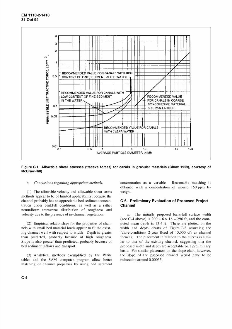
8/14/2019 Channel Stability Assessment for Flood Control Projects
http://slidepdf.com/reader/full/channel-stability-assessment-for-flood-control-projects 111/117
EM 1110-2-141831 Oct 94
Figure C-1. Allowable shear stresses (tractive forces) for canals in granular materials (Chow 1959), courtesy of
McGraw-Hill)
e. Conclusions regarding appropriate methods.
(1) The allowable velocity and allowable shear stress
methods appear to be of limited applicability, because the
channel probably has an appreciable bed sediment concen-
tration under bankfull conditions, as well as a rather
nonuniform transverse distribution of roughness and
velocity due to the presence of in-channel vegetation.
(2) Empirical relationships for the properties of chan-
nels with small bed material loads appear to fit the exist-
ing channel well with respect to width. Depth is greater
than predicted, probably because of high roughness.
Slope is also greater than predicted, probably because of
bed sediment inflows and transport.
(3) Analytical methods exemplified by the White
tables and the SAM computer program allow better
matching of channel properties by using bed sediment
concentration as a variable. Reasonable matching is
obtained with a concentration of around 150 ppm by
weight.
C-6. Preliminary Evaluation of Proposed Project
Channel
a. The initially proposed bank-full surface width
(see C-4 above) is 200 + 6 × 16 = 296 ft, and the com-
puted mean depth is 13.4 ft. These are plotted on the
width and depth charts of Figure C-2 assuming the
future-conditions 2-year flood of 15,000 cfs as channel
forming. The placement in relation to the curves is simi-
lar to that of the existing channel, suggesting that the
proposed width and depth are acceptable on a preliminary
basis. For similar placement on the slope chart, however,
the slope of the proposed channel would have to be
reduced to around 0.00035.
C-4

8/14/2019 Channel Stability Assessment for Flood Control Projects
http://slidepdf.com/reader/full/channel-stability-assessment-for-flood-control-projects 112/117

8/14/2019 Channel Stability Assessment for Flood Control Projects
http://slidepdf.com/reader/full/channel-stability-assessment-for-flood-control-projects 113/117
EM 1110-2-141831 Oct 94
Figure C-2. Varmint Creek channel properties compared with tentative width, depth, and slope charts from
paragraph 5-5
C-6

8/14/2019 Channel Stability Assessment for Flood Control Projects
http://slidepdf.com/reader/full/channel-stability-assessment-for-flood-control-projects 114/117
EM 1110-2-141831 Oct 94
C-7

8/14/2019 Channel Stability Assessment for Flood Control Projects
http://slidepdf.com/reader/full/channel-stability-assessment-for-flood-control-projects 115/117
EM 1110-2-141831 Oct 94
Table C-4
Computed Alternative Sets of Stable Channel Properties Using SAM Program
Stable Channels for Q = 4500.0 C,ppm = 150.0 D50 = .500
K Bottom
Width
ft
Depth
ft
Energy
Slope
ft/ft
Cmpos’t
n-value
Hyd
Radius
ft
Vel
fps
Froude
Number
Shear
Stress
#/sf
Bed(2)
Regime
1 13. 13.7 .000972 .0436 7.33 4.01 .19 .83 TL
2 26. 13.5 .000672 .0422 7.71 3.56 .17 .57 TL
3 39. 12.9 .000548 .0409 7.84 3.36 .16 .44 TL
4 52. 12.3 .000479 .0396 7.85 3.24 .16 .37 TL
5 65. 11.6 .000434 .0384 7.78 3.16 .16 .31 LO
6 78. 10.9 .000402 .0373 7.65 3.10 .17 .27 LO
7 91. 10.3 .000380 .0362 7.49 3.06 .17 .24 LO
8 104. 9.7 .000363 .0352 7.31 3.03 .17 .22 LO
117. 9.2 .000351 .0343 7.11 3.00 .17 .20 LO
10 130. 8.7 .000341 .0334 6.91 2.98 .18 .19 LO
11 143. 8.3 .000334 .0327 6.70 2.96 .18 .17 LO
12 156. 7.9 .000329 .0320 6.49 2.93 .18 .16 LO
13 169. 7.5 .000325 .0313 6.29 2.92 .19 .15 LO
14 182. 7.1 .000322 .0307 6.10 2.90 .19 .14 LO
15 195. 6.8 .000321 .0302 5.91 2.88 .19 .14 LO
16 208. 6.5 .000320 .0297 5.73 2.86 .20 .13 LO
17 221. 6.3 .000319 .0293 5.55 2.84 .20 .12 LO
18 234. 6.0 .000320 .0289 5.39 2.83 .20 .12 LO
19 247. 5.8 .000320 .0285 5.23 2.81 .21 .12 LO
20 260. 5.6 .000321 .0282 5.08 2.79 .21 .12 LO
Results at Minimum Stream Power
21 223. 6.2 .000319 .0292 5.53 2.84 .20 .12 LO
Notes: (1) Cross Section Properties: LEFT BANK RIGHT BANK
SIDE SLOPE, [H:1V] = 5.000 5.000
Ks, FT = 5.189 5.189
n-VALUE = .04500 .04500
(2) REGIMES: LO = LOWER, TL = TRANSITIONAL-LOWER, TU = TRANSITIONAL-UPPER, UP = UPPER
C-8

8/14/2019 Channel Stability Assessment for Flood Control Projects
http://slidepdf.com/reader/full/channel-stability-assessment-for-flood-control-projects 116/117
EM 1110-2-141831 Oct 94
Figure C-3. Slope versus width curves for discharges of 4,500 cfs (Table C-4) and 51,000 cfs, based on output from
SAM program
C-9

8/14/2019 Channel Stability Assessment for Flood Control Projects
http://slidepdf.com/reader/full/channel-stability-assessment-for-flood-control-projects 117/117
EM 1110-2-141831 Oct 94
Appendix DNotation
A Cross-section area
b Mean width
C Sediment concentration
d Depth of flow
D Grain size
D50 Median sediment size
g Gravitational acceleration
k Grain roughness
L Channel length between inflection points
n Manning’s roughness
P Wetted perimeter
Q Discharge
Qs Bed material discharge
R Hydraulic radius
s Dry relative density of sediment
S Slope; hydraulic slope
V Mean velocity
V* Shear velocity defined as τ0 / ρ
W Width
0 Superscript indicating no change
+ Superscript indicating an increase
γ Specific weight of water
γ s′ submerged specific weight of sediment
ν Kinematic viscosity
ρ Fluid density
τ0 Average boundary shear stress in uniform flow