
Channel & Shoe Arrangement CALSENS · 2) Gate Trabel Indicator 3) Headstock & Extn. Spindle 4)...
6
TECHNICAL DATA SHEETS CALSENS SLUICE/GATE VALVES
Transcript of Channel & Shoe Arrangement CALSENS · 2) Gate Trabel Indicator 3) Headstock & Extn. Spindle 4)...

Valves with Reduction Gear & Actuator arrangement
Valves Actuator arrangement
CALSENS PRIVATE LIMITEDAn ISO 9001 : 2008 Registered Firm6/1A, British Indian Street, Kolkata 700 069 Phone : 2248 6527, 3293 8984, Fax : 91 33 2210 4154 e-mail : [email protected], Website : www.calsens.com Offices/Dealers at : Chennai Bhubaneshwar Mumbai Pune Hyderabad Rourkela Ranchi Surat New Delhi
Spur/Bevel Gear Arrangement
Brass lined CI Channel on the body and bronze shoe on the wedge is used as anti-friction device to minimise the friction between the guide surfaces of Body/Wedge. Recommended for actuator and horizontal Operation.
In order to make easy operation of the large diameter Valves from Size 300 mm to 700 mm without thrust ball bearing and Valves from 700 mm and above with thrust ball bearings.
Channel & Shoe Arrangement
For underground operation of Valve at place inaccessible, the Valve is operated through the hand wheel of Headstock and extension shaft.
Thrust ball bearings are provided on both sides of the collars to minimise the friction of rotary force between collar, cover and stuffing box which help an easy operation of the Valves.
Head Stock & Extension Arrangement Thrust Ball Bearing Arrangement
For changing of gland packing when the Valve is fully open. It also maintains condition of flow undisturbed by sealing the atmosphere within the Valves.
By-pass arrangement is provided to reduce the unbalanced load and to supply water for priming.
By-Pass Arrangement for Sluice Valves Back Seating Arrangement
T E C H N I C A L D A T A S H E E T S
CALSENS
GR
AP
HIQ
UE
IN
TER
NA
TIO
NA
L, M
AY
201
4 (1
000)
SLUICE/GATEV A L V E S

CALSENS Sluice Valves are now a name to reckon among engineers throughout the country. Each valve is specially tested under strict supervision and quality control. Unique design, superb production and hard gained field experience have made these valve reliable. Maximum utility is provided by these valves in Irrigation, River Control installations, Industrial Plants & Projects and in the works of Public Health Projects etc.
CALSENS guarantees a trouble free service for years for their Valves.
APPLICATIONSIt is applicable to handle clear water with turbidity upto 5000 ppm and temperature not more than 450C. For handling hot water and steam, SS trims are recommended. Also suitable in the boiler line, for non-IBR Applications.
STANDARDS1) IS 780/84 – 50 mm to 300 PN 1.0 to 1.62) IS 2906/84 – 350 mm to 1200 PN 0.4 to 1.6
MATERIALS & CONSTRUCTION1) Body, Bonnet Wedge – Grey Cast Iron,
Confirming to IS-210. Gr. FG-200/260
2) Spindle – High Tensile Brass/13% Cr. Stainless Steel
3) Spindle Nut – Leaded Gun Metal4) Seat & Face Rings – Leaded Gun Metal in Body
& Wedge. Rings of SS can be supplied on demand
5) Hand Wheel & Cap – Grey Cast Iron, IS-210 Gr. FG-200/260
6) Flanges – Faced and Drilled to IS 1538/1969, BS 10T-D/E On demand drilling as per DIN, ANSI B 16.5 & undrilled possible.
7) Operation – Anti-clockwise opening, Clockwise closing.
ACCESSORIESFollowing accessories can be supplied on specific request :1) Spur/Worm/Bevel Gear2) Gate Trabel Indicator3) Headstock & Extn. Spindle4) Drain Plug/Scour Plug5) Shoe-Channel6) Back Seating7) Actuator8) By-Pass9) Thrust ball bearing for Anti-friction movement.
Test Pressure for Sluice Valves
PN Rating
Test for Body/SeatTest Pressure Mpa
(Gauge)
PN 1.0Body Seat
1.5 1.0
PN 1.6Body Seat
2.4 1.6
Current Standard — IS 14846 : 2000
50 mm to 600 mm — PN 1.0 & PN 1.6 rating
700 mm to 1200 mm — PN 1.0 rating
CAST IRON SLUICE VALVE (IS : 14846/2000) NON-RISING SPINDLE
For 50 MM to 150 MM Dia, Valve For 500 MM to 1200 MM Dia, Valve
15 Back Seat Bush (for 350 and above) 1 L.T.B IS:318Gr. LTB-2
14 Thrust Plate 1 Cast Iron IS:210 Gr. & G - 200
13 Nuts & Bolts AS Reqd. Carbon Steel IS:1363CL-4 & 4.6
12 Wedge Ring 2 S.S./L.T.B. AISI : 304/IS:318 Gr. L.T.B.-2
11 Body Ring 2 S.S./L.T.B. AISI : 304/IS:318 Gr. L.T.B.-2
10 Wedge 1 Cast Iron IS : 210 Gr. FG-200
9 Spindle Nut 1 L.T.B. IS : 318 Gr. FG-200
8 Body 1 Cast Iron IS : 210 Gr. FG-200
7 Cover 1 Cast Iron IS : 210 Gr. FG-200
6 Gasket — Rubber IS : 638 Type-B
5 Packing — Jute & HEMP. IS : 5414
4 Top Cover 1 Cast Iron IS : 210 Gr. FG-200
3 Gland 1 Cast Iron IS : 210 Gr. FG-200
2 Spindle 1 SS AISI : 410
1 Hand Wheel 1 Cast Iron IS : 210 Gr. FG-200
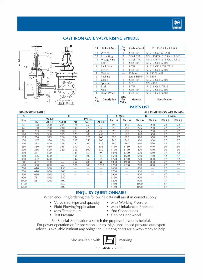
SL No. Description Qnty. Per Value Material Specification
14 Bolts & Nuts AS Reqd Carbon Steel IS : 1363 CL - 4.6 & 4
13 Wedge 1 Cast Iron IS : 210 Gr. FG - 20012 Body Ring 2 S.S./L.T.B. AISI : 304/IS : 318 Gr. L.T.B-211 Wedge Ring 2 S.S./L.T.B. AISI : 304/IS : 318 Gr. L.T.B-210 Body 1 Cast Iron IS : 210 Gr. FG-2009 Back Seat 1 L.T.B. IS : 318 GR. L.T.B. TB-28 Cover 1 Cast Iron IS : 210 Gr. FG-2007 Gasket — Rubber IS : 638 Type-B6 Packing — Jute & HEMP. IS : 54145 Gland 1 Cast Iron IS : 210 Gr. FG-2004 Spindle 1 S. S. AISI - 4103 Bush 1 L.T.B. IS : 318 Gr. L.T.B.-22 Yoke 1 Cast Iron IS : 210 Gr. FG-2001 Hand Wheel 1 Cast Iron IS : 210 Gr. FG-200
Sl. No. Description
Qty. Per
ValueMaterial Specification
CAST IRON GATE VALVE RISING SPINDLE
DIMENSION TABLE ALL DIMENSION ARE IN MMA B C Max. D E Min.
Size PN 1.0 PN 1.6 PN 1.0 PN 1.6 PN 1.0 PN 1.6 PN 1.0 PN 1.6PD ALT-I ALT-II PD ALT-I ALT-II50 178 250 215 178 250 215 490 490 225 280 22 2265 190 270 230 190 270 230 550 550 225 280 22 2280 203 280 230 203 280 230 590 590 225 280 22 22
100 229 300 255 229 300 255 620 620 320 360 27 27125 254 325 266 254 325 266 690 690 320 360 27 27150 267 350 280 267 350 280 740 740 320 360 27 27200 292 400 318 292 400 318 980 980 360 450 32 32250 330 450 355 330 450 355 1130 1130 400 640 36 36300 356 500 380 356 500 380 1190 1190 400 640 36 36350 381 550 — 381 550 690 1480 1390 500 640 37 42400 406 600 — 406 600 750 1680 1630 640 730 42 47450 432 650 — 432 650 820 1720 1770 720 800 47 52 500 457 700 — 457 700 880 1990 1900 720 800 47 52600 508 800 — 508 800 1000 2280 2200 720 800 47 57700 610 900 1130 — — — 2600 — 800 — 62 —750 610 950 1200 — — — 2750 — 900 — 67 —800 660 1000 1250 — — — 2900 — 900 — 67 —900 711 1100 1380 — — — 3150 — 900 — 77 —
1000 811 1200 1500 — — — 3420 — 900 — 77 —1100 — — 1650 — — — 3780 — 1000 — 87 —1200 — — 1800 — — — 4140 — 1000 — 87 —
Also available with marking
IS : 14846 - 2000
ENQUIRY QUESTIONNAIREWhen enquiring/ordering the following data will assist in correct supply :
For Special Application a sketch the proposed layout is helpful.For power operation or for operation against high unbalanced pressure our expert
advice is available without any obligation. Our engineers are always ready to help.
Valve size, type and quantity Fluid Flowing/Application Max Temperature Test Pressure
Max Working Pressure Max Unbalanced Pressure End Connections Cap or Handwheel
DIMENSION TABLE ALL DIMENSION ARE IN MM
A B C Mox. D E Min.Size PN 1.0 PN 1.6 PN 1.0 PN 1.6 PN 1.0 PN 1.6 PN 1.0 PN 1.6
PD ALT-I ALT-II PD ALT-I ALT-II50 178 250 215 178 250 215 365 365 225 280 22 2265 190 270 230 190 270 230 380 380 225 280 22 2280 203 280 230 203 280 230 425 425 225 280 22 22
100 229 300 225 229 300 255 470 470 320 360 27 27125 254 325 266 254 325 266 485 485 320 360 27 27150 267 350 280 267 350 280 595 595 320 360 27 27200 292 400 318 292 400 318 725 725 360 450 32 32250 330 450 355 330 450 355 835 835 400 640 36 36300 356 500 380 356 500 380 910 910 400 640 36 36350 381 550 - 381 550 690 1020 1030 500 640 37 42400 406 600 - 406 600 750 1110 1110 640 730 42 47450 432 650 - 432 650 820 1200 1210 720 800 47 52500 457 700 - 457 700 880 1300 1340 720 800 47 52600 508 800 - 508 800 1000 1500 1500 720 800 47 57700 610 900 1130 - - - 1670 - 800 - 62 -750 610 950 1200 - - - 1780 - 900 - 67 -800 660 1000 1250 - - - 1930 - 900 - 67 -900 711 1100 1380 - - - 2080 - 900 - 77 -
1000 811 1200 1500 - - - 2200 - 900 - 77 -1100 - - 1650 - - - 2450 - 1000 - 87 -1200 - - 1800 - - - 2580 - 1000 - 87 -
PARTS LIST
PARTS LIST

CALSENS Sluice Valves are now a name to reckon among engineers throughout the country. Each valve is specially tested under strict supervision and quality control. Unique design, superb production and hard gained field experience have made these valve reliable. Maximum utility is provided by these valves in Irrigation, River Control installations, Industrial Plants & Projects and in the works of Public Health Projects etc.
CALSENS guarantees a trouble free service for years for their Valves.
APPLICATIONSIt is applicable to handle clear water with turbidity upto 5000 ppm and temperature not more than 450C. For handling hot water and steam, SS trims are recommended. Also suitable in the boiler line, for non-IBR Applications.
STANDARDS1) IS 780/84 – 50 mm to 300 PN 1.0 to 1.62) IS 2906/84 – 350 mm to 1200 PN 0.4 to 1.6
MATERIALS & CONSTRUCTION1) Body, Bonnet Wedge – Grey Cast Iron,
Confirming to IS-210. Gr. FG-200/260
2) Spindle – High Tensile Brass/13% Cr. Stainless Steel
3) Spindle Nut – Leaded Gun Metal4) Seat & Face Rings – Leaded Gun Metal in Body
& Wedge. Rings of SS can be supplied on demand
5) Hand Wheel & Cap – Grey Cast Iron, IS-210 Gr. FG-200/260
6) Flanges – Faced and Drilled to IS 1538/1969, BS 10T-D/E On demand drilling as per DIN, ANSI B 16.5 & undrilled possible.
7) Operation – Anti-clockwise opening, Clockwise closing.
ACCESSORIESFollowing accessories can be supplied on specific request :1) Spur/Worm/Bevel Gear2) Gate Trabel Indicator3) Headstock & Extn. Spindle4) Drain Plug/Scour Plug5) Shoe-Channel6) Back Seating7) Actuator8) By-Pass9) Thrust ball bearing for Anti-friction movement.
Test Pressure for Sluice Valves
PN Rating
Test for Body/SeatTest Pressure Mpa
(Gauge)
PN 1.0Body Seat
1.5 1.0
PN 1.6Body Seat
2.4 1.6
Current Standard — IS 14846 : 2000
50 mm to 600 mm — PN 1.0 & PN 1.6 rating
700 mm to 1200 mm — PN 1.0 rating
CAST IRON SLUICE VALVE (IS : 14846/2000) NON-RISING SPINDLE
For 50 MM to 150 MM Dia, Valve For 500 MM to 1200 MM Dia, Valve
15 Back Seat Bush (for 350 and above) 1 L.T.B IS:318Gr. LTB-2
14 Thrust Plate 1 Cast Iron IS:210 Gr. & G - 200
13 Nuts & Bolts AS Reqd. Carbon Steel IS:1363CL-4 & 4.6
12 Wedge Ring 2 S.S./L.T.B. AISI : 304/IS:318 Gr. L.T.B.-2
11 Body Ring 2 S.S./L.T.B. AISI : 304/IS:318 Gr. L.T.B.-2
10 Wedge 1 Cast Iron IS : 210 Gr. FG-200
9 Spindle Nut 1 L.T.B. IS : 318 Gr. FG-200
8 Body 1 Cast Iron IS : 210 Gr. FG-200
7 Cover 1 Cast Iron IS : 210 Gr. FG-200
6 Gasket — Rubber IS : 638 Type-B
5 Packing — Jute & HEMP. IS : 5414
4 Top Cover 1 Cast Iron IS : 210 Gr. FG-200
3 Gland 1 Cast Iron IS : 210 Gr. FG-200
2 Spindle 1 SS AISI : 410
1 Hand Wheel 1 Cast Iron IS : 210 Gr. FG-200
SL No. Description Qnty. Per Value Material Specification
14 Bolts & Nuts AS Reqd Carbon Steel IS : 1363 CL - 4.6 & 4
13 Wedge 1 Cast Iron IS : 210 Gr. FG - 20012 Body Ring 2 S.S./L.T.B. AISI : 304/IS : 318 Gr. L.T.B-211 Wedge Ring 2 S.S./L.T.B. AISI : 304/IS : 318 Gr. L.T.B-210 Body 1 Cast Iron IS : 210 Gr. FG-2009 Back Seat 1 L.T.B. IS : 318 GR. L.T.B. TB-28 Cover 1 Cast Iron IS : 210 Gr. FG-2007 Gasket — Rubber IS : 638 Type-B6 Packing — Jute & HEMP. IS : 54145 Gland 1 Cast Iron IS : 210 Gr. FG-2004 Spindle 1 S. S. AISI - 4103 Bush 1 L.T.B. IS : 318 Gr. L.T.B.-22 Yoke 1 Cast Iron IS : 210 Gr. FG-2001 Hand Wheel 1 Cast Iron IS : 210 Gr. FG-200
Sl. No. Description
Qty. Per
ValueMaterial Specification
CAST IRON GATE VALVE RISING SPINDLE
DIMENSION TABLE ALL DIMENSION ARE IN MMA B C Max. D E Min.
Size PN 1.0 PN 1.6 PN 1.0 PN 1.6 PN 1.0 PN 1.6 PN 1.0 PN 1.6PD ALT-I ALT-II PD ALT-I ALT-II50 178 250 215 178 250 215 490 490 225 280 22 2265 190 270 230 190 270 230 550 550 225 280 22 2280 203 280 230 203 280 230 590 590 225 280 22 22
100 229 300 255 229 300 255 620 620 320 360 27 27125 254 325 266 254 325 266 690 690 320 360 27 27150 267 350 280 267 350 280 740 740 320 360 27 27200 292 400 318 292 400 318 980 980 360 450 32 32250 330 450 355 330 450 355 1130 1130 400 640 36 36300 356 500 380 356 500 380 1190 1190 400 640 36 36350 381 550 — 381 550 690 1480 1390 500 640 37 42400 406 600 — 406 600 750 1680 1630 640 730 42 47450 432 650 — 432 650 820 1720 1770 720 800 47 52 500 457 700 — 457 700 880 1990 1900 720 800 47 52600 508 800 — 508 800 1000 2280 2200 720 800 47 57700 610 900 1130 — — — 2600 — 800 — 62 —750 610 950 1200 — — — 2750 — 900 — 67 —800 660 1000 1250 — — — 2900 — 900 — 67 —900 711 1100 1380 — — — 3150 — 900 — 77 —
1000 811 1200 1500 — — — 3420 — 900 — 77 —1100 — — 1650 — — — 3780 — 1000 — 87 —1200 — — 1800 — — — 4140 — 1000 — 87 —
Also available with marking
IS : 14846 - 2000
ENQUIRY QUESTIONNAIREWhen enquiring/ordering the following data will assist in correct supply :
For Special Application a sketch the proposed layout is helpful.For power operation or for operation against high unbalanced pressure our expert
advice is available without any obligation. Our engineers are always ready to help.
Valve size, type and quantity Fluid Flowing/Application Max Temperature Test Pressure
Max Working Pressure Max Unbalanced Pressure End Connections Cap or Handwheel
DIMENSION TABLE ALL DIMENSION ARE IN MM
A B C Mox. D E Min.Size PN 1.0 PN 1.6 PN 1.0 PN 1.6 PN 1.0 PN 1.6 PN 1.0 PN 1.6
PD ALT-I ALT-II PD ALT-I ALT-II50 178 250 215 178 250 215 365 365 225 280 22 2265 190 270 230 190 270 230 380 380 225 280 22 2280 203 280 230 203 280 230 425 425 225 280 22 22
100 229 300 225 229 300 255 470 470 320 360 27 27125 254 325 266 254 325 266 485 485 320 360 27 27150 267 350 280 267 350 280 595 595 320 360 27 27200 292 400 318 292 400 318 725 725 360 450 32 32250 330 450 355 330 450 355 835 835 400 640 36 36300 356 500 380 356 500 380 910 910 400 640 36 36350 381 550 - 381 550 690 1020 1030 500 640 37 42400 406 600 - 406 600 750 1110 1110 640 730 42 47450 432 650 - 432 650 820 1200 1210 720 800 47 52500 457 700 - 457 700 880 1300 1340 720 800 47 52600 508 800 - 508 800 1000 1500 1500 720 800 47 57700 610 900 1130 - - - 1670 - 800 - 62 -750 610 950 1200 - - - 1780 - 900 - 67 -800 660 1000 1250 - - - 1930 - 900 - 67 -900 711 1100 1380 - - - 2080 - 900 - 77 -
1000 811 1200 1500 - - - 2200 - 900 - 77 -1100 - - 1650 - - - 2450 - 1000 - 87 -1200 - - 1800 - - - 2580 - 1000 - 87 -
PARTS LIST
PARTS LIST

Valves with Reduction Gear & Actuator arrangement
Valves Actuator arrangement
CALSENS PRIVATE LIMITEDAn ISO 9001 : 2008 Registered Firm6/1A, British Indian Street, Kolkata 700 069 Phone : 2248 6527, 3293 8984, Fax : 91 33 2210 4154 e-mail : [email protected], Website : www.calsens.com Offices/Dealers at : Chennai Bhubaneshwar Mumbai Pune Hyderabad Rourkela Ranchi Surat New Delhi
Spur/Bevel Gear Arrangement
Brass lined CI Channel on the body and bronze shoe on the wedge is used as anti-friction device to minimise the friction between the guide surfaces of Body/Wedge. Recommended for actuator and horizontal Operation.
In order to make easy operation of the large diameter Valves from Size 300 mm to 700 mm without thrust ball bearing and Valves from 700 mm and above with thrust ball bearings.
Channel & Shoe Arrangement
For underground operation of Valve at place inaccessible, the Valve is operated through the hand wheel of Headstock and extension shaft.
Thrust ball bearings are provided on both sides of the collars to minimise the friction of rotary force between collar, cover and stuffing box which help an easy operation of the Valves.
Head Stock & Extension Arrangement Thrust Ball Bearing Arrangement
For changing of gland packing when the Valve is fully open. It also maintains condition of flow undisturbed by sealing the atmosphere within the Valves.
By-pass arrangement is provided to reduce the unbalanced load and to supply water for priming.
By-Pass Arrangement for Sluice Valves Back Seating Arrangement
T E C H N I C A L D A T A S H E E T S
CALSENS
GR
AP
HIQ
UE
IN
TER
NA
TIO
NA
L, M
AY
201
4 (1
000)
SLUICE/GATEV A L V E S


![Next Stop: Alvik Plug in your SL controller here to START Channel Information: 1. Channel [V] 2. Classic Music 3. Pop Music 4. Rock & Roll 5......](https://static.fdocuments.us/doc/165x107/56649e445503460f94b37bac/next-stop-alvik-plug-in-your-sl-controller-here-to-start-channel-information.jpg)


