Changes in Materials for Motion and Design
9
Changes in Materials for Motion and Design Since publication of the Motion and Design Teacher’s Guide and Student Investigation book, metal eyelets have replaced the brass eyelets used to assemble the propeller units. This change in materials affects Lessons 11, 17, and Additional Assessment 2 of the Motion and Design unit and requires minor revisions to the instructions in the unit’s printed materials. This errata set includes the following: • For the Motion and Design Teacher’s Guide Second Edition, Section 3: Materials Management and Safety—revised page 5 • For the Motion and Design Teacher’s Guide Second Edition, Section 4: Unit Investigations and Blackline Masters—revised pages 102–105, and 153 • For the Motion and Design Teacher’s Guide Second Edition, Section 5: Student Assessment, Additional Assessment 2—revised page 21 • For the Motion and Design Student Investigation book—revised page 48 Photocopy and distribute these replacement pages as needed. If you have questions about these changes or about the module in general, call Carolina’s product information staff at 800-227-1150 (8 a.m.–5 p.m. ET, M–F), or email [email protected]. 1107
Transcript of Changes in Materials for Motion and Design
Changes in Materialsfor Motion and Design
Since publication of the Motion and Design Teacher’s Guide and Student Investigation book, metal eyelets have replaced the brass eyelets used to assemble the propeller units. This change in materials affects Lessons 11, 17, and Additional Assessment 2 of the Motion and Design unit and requires minor revisions to the instructions in the unit’s printed materials.
This errata set includes the following:
• For the Motion and Design Teacher’s Guide Second Edition, Section 3: Materials Management and Safety—revised page 5 • For the Motion and Design Teacher’s Guide Second Edition, Section 4: Unit Investigations and Blackline Masters—revised pages 102–105, and 153 • For the Motion and Design Teacher’s Guide Second Edition, Section 5: Student Assessment, Additional Assessment 2—revised page 21
• For the Motion and Design Student Investigation book—revised page 48
Photocopy and distribute these replacement pages as needed.
If you have questions about these changes or about the module in general, call Carolina’s product information staff at 800-227-1150 (8 a.m.–5 p.m. ET, M–F), or email [email protected].
1107

Materials Management and Safety / 5STC® / Motion and Design
Item Description Item Description Lesson Number in Teacher’s Guide on Packing List (Quantity Used)
Adding machine tape,at least 80 m (2621⁄2 ft)
Adding machine paper roll 7 (40 m), 10 (40 m)
Black permanent marker Fine-point black permanent marker 1 (1), 2 (1), 14 (1)
Eyelets Pack of 25 metal eyelets 11 (20), 15 (8), 17 (22),Assessment 2 (22)
Buckets and lids 1-gal plastic pailLid for 1-gal plastic pail
1 (11), 2 (11), 5 (10), 9 (10), 10 (10),11 (11), 12 (10), 13 (10), 15 (11),16 (11), 17 (11), Assessment 2 (11)
Circle templates Pack of 10 circle templates 2 (10), 5 (10), 9 (10), 14 (6), 16 (10),17 (10), Assesment 2 (10)
Large metal washers Pack of 30 large metal washers 3 (10), 5 (30), 15 (pack), 17 (pack),Assessment 2 (pack)
Large rubber bands, No. 64 Pack of 40 #64 rubber bands 11 (30), 12 (9), 15 (12), 17 (pack),Assessment 2 (pack)
Measuring tapes, 100 cm (39 in) Pack of 10 metric measuring tapes 1 (10), 3 (1), 4 (1), 5 (1), 15 (6),17 (10), Assesment 2 (6)
Pieces of cardboard, 21.5 × 28 cm(81⁄2 × 11 in)
Pack of 10 81⁄2×11in sheets of finecardboard
3 (10), 4 (10), 5 (10), 9 (10), 15 (5),17 (10)
Screw hooks, 0.3 cm(1⁄8 in) diameter
Pack of 11 screw hooks 11 (10), 15 (4), 17 (11),Assessment 2 (11)
Pack of assorted dots
Self-stick blue dots 60 3⁄4in blue dots 7 (30), 10 (30)
Self-stick green dots 30 3⁄4in green dots 7 (30)
Self-stick red dots 60 3⁄4in red dots 7 (30), 10 (30)
Sets of colored pencils Set of colored pencils 2 (10), 4 (10), 5 (10), 9 (10), 14 (6),16 (10), 17 (10), Assessment 2 (10)
Sheets of three-hole, 10 mm (1⁄4 in)graph paper with light blue lines,21.5 × 28 cm (81⁄2 × 11 in)
Pack of 300 three-hole graph sheets 1 (300)
Small bookends with nonslip base,13h × 12w × 13d cm (5h × 43⁄4w ×5d in), about 141 g (5 oz)
Small bookend with nonslip base 3 (10), 4 (10), 5 (10)
Small metal washers Pack of 220 No. 10 steel washers 3 (160), 4 (160), 5 (160), 15 (pack),17 (pack), Assessment 2 (pack)
Small plastic cups, 30 mL (1 oz) Pack of 10 1-oz plastic cups 3 (10)
Blocks of wood, 5 × 8 × 9 cm(2 × 3 × 31⁄2 in)
Pack of 20 blocks of wood 4 (20), 5 (20), 15 (5)
Box of jumbo paper clips Box of 100 jumbo paper clips 3 (20), 4 (20 + box), 5 (box), 15 (box),17 (box), Assessment 2 (box)
Materials List This Materials List chart is a cross-reference guide for the materials supplied in the Motion and Designunit kit (Item Number 97-3001). It gives the description of each item as it is listed in the lessons of theTeacher’s Guide, and provides the cross-reference description of the item as it appears on the kit’spacking list, which you will find in the Motion and Design unit kit box(es). Please note that the metricand English equivalent measurements in this unit are approximate. For additional information about thematerials in this unit kit, please contact Carolina at 800-227-1150 or www.carolina.com.
M&D_TG Tab 3 MMS:M&D_TG Tab 3 MMS 7/19/11 1:30 PM Page 5

102 / Building a Propeller-Driven Vehicle
LESSON 11
STC® / Motion and Design
Figure 11-1
Looking at apropeller
Figure 11-2
Storing energy ina rubber band
the vehicle might move with a burst of speed. This is because the rubber band isat its maximum tension. When first released, the rubber band produces thegreatest force and therefore the highest propeller speed.
Propellers must be strong enough to withstand high speeds and great force.Airplane designers must carefully match the size, shape, and number of bladeswith the aircraft and its engine to ensure top performance and safety. As eachgroup observes its propeller-driven vehicle in this lesson, encourage them to lookat how they mounted the propeller on the vehicle and to discuss why it ispositioned in this way. For example, students may notice that the propeller ismounted high so the blades can turn freely without hitting the table below. Initialobservations like these will help students prepare for Lesson 12, in which theyevaluate specific design features of the propeller-driven vehicle and compare thevehicle’s design with that of the axle-driven vehicle.
First the rubber band twistsinto a series of simple knots.
As it tightens, the knots themselvesare twisted into larger knots, beginningat the base of the rubber band.
Propeller andattachments
move forward
Spinningpropellerpushes airbackward

Building a Propeller-Driven Vehicle / 103
For each student1 science notebook
Safety goggles
For each group of three students1 propeller unit (includes propeller, screw hook, eyelets, and white
connector)1 bucket of building pieces3 No. 64 rubber bands, connected
For the classMaterials for teacher to assemble propeller units:10 propellers10 hooks20 eyelets10 white connectors (from students’ buckets or class bucket)
Bucket of extra building pieces1 sheet of newsprint
Assorted colored markersMasking tapeTrade books, photographs, or illustrations showing propeller-driven vehicles
1. If you have not already done so, assemble one propeller unit for each group.Use Figure 11-3 as a guide. For each propeller unit you will need onepropeller, two eyelets, one white connector, and one hook. Students will attachthe three connected rubber bands to the propeller unit’s hook after they buildtheir vehicles. Note that the flared ends of the two eyelets are on the same sideof the white connector. These ends rub together as the propeller spins. Makesure that the hook faces the concave (dished in) side of the propeller blades.The hub (center of the propeller) is rounded on one end and has a tinycorkscrew on the other. The hook goes into the rounded end. Turn the hookclockwise about six turns in the propeller hub. When the hook becomes verydifficult to turn, it is seated. The plastic around the hook will lighten in color.Check to be sure the plastic shaft, or opening on the propeller into which thehook attaches, has not split.
2. Using the class bucket of building pieces and the technical drawing fromLesson 2 (Figure 2-2), build a standard vehicle that you will use in the FinalActivities. Attach a connected rubber band to the axle.
3. To familiarize yourself with the building process students will engage induring this lesson, assemble a propeller-driven vehicle using the technicaldrawing in Figure 11-4.
4. Label the sheet of newsprint “Design Ideas for Propeller-Driven Vehicles.”Date and hang the sheet.
5. Collect and display trade books, photographs, or illustrations that showpropeller-driven vehicles.
6. Connect three large rubber bands. Each group needs one set of connectedrubber bands.
7. Arrange the rubber bands, safety goggles, buckets of building pieces, andpropeller units at the distribution center. Using an index card, label thepropeller units “Take one.”
LESSON 11
Materials
Preparation
STC® / Motion and Design

104 / Building a Propeller-Driven Vehicle
1. Involve students in a brainstorming session in which they describe whatthey know about propeller-driven vehicles. Let students know that they willuse a technical drawing to build a propeller-driven vehicle in this lesson.They will analyze its design features in Lesson 12.
2. Focus students’ attention on one of the assembled propeller units. Point outthe white connector and how the connected rubber bands attach to thepropeller hook. Ask students to think about how the white connector couldbe used to attach the propeller to the vehicle and where on the vehicle therubber band could be connected.
3. Ask students to think about vehicle design features that might be necessaryto move their vehicles with a propeller. Encourage them to share theirideas. For example, students might say the propeller must be high in the airso it will not hit the ground as it spins. Others might suggest that thepropeller must be in the front or that the rubber band must be taut andconnected straight across from the propeller. List their design ideas on thesheet of newsprint titled “Design Ideas for Propeller-Driven Vehicles.”
LESSON 11
Procedure
STC® / Motion and Design
Figure 11-3
Preparing thepropellers
Screwhook
Whiteconnector
EyeletsPropeller
Front of propellerwith “corkscrew”opening, mustface forward
Screw fits intorounded rearof propeller
Note thateyelets facein oppositedirections,both on frontof connector
Rubber bandwill loop overhook
Eyelet fitsinto holeon front ofconnector
Cross-section ofpropellerassembly

Building a Propeller-Driven Vehicle / 105
LESSON 11
STC® / Motion and Design
Figure 11-4
Side View
Gray rod
Gray rodRed rodYellow rod
Yellow rod
Red rod
Red rod
Red rod
Green rod
Orange connector
Tan
connector
Red connector
Green rod
Red
connector
Tan connector
White
connector
Green rod
Green rod
Red rod
White connector
Red connector
Blue rod
Red connector
Tan connector
Red rod
Red connector
Red connector
Top View
Front
View
Yellow
connectors
Small w
heel

153STC® / Motion and Design
This post-unit assessment is matched to the pre-unit assessment in Lesson 1. By comparing individual and class responses to activities in this assessment withthose from Lesson 1, you can document each student’s learning over the courseof the unit. In Lesson 1, students developed two lists: “What We Know about theMotion and Design of Vehicles” and “What We Want to Find Out about Motionand Design.” They also designed, built, and tested their own vehicle on the basisof a set of requirements. As students revisit the class brainstorming lists and therecords of the vehicle they made in Lesson 1 and compare them with those inthis activity, they might realize how much they have learned about technologicaldesign and the relationships between force and motion.
For each student
1 science notebook (with entries from Lesson 1 and drawing from Lesson 2)1 pencil with eraser
Safety goggles
For each group of three students1 bucket of building pieces (see blackline master Building Pieces for Each
Group from Lesson 1)
For the class2 class brainstorming lists, “What We Know about the Motion and Design of
Vehicles” and “What We Want to Find Out about Motion and Design” (from Lesson 1)
1 sheet of newsprint1 spool of light string
Cardboard sails, 23 × 30 cm (9 × 12 in) Small rubber bands, No. 16Large rubber bands, No. 64Propeller units (includes propeller, screw hook, eyelets, and white connector)Strips of Masonite™, 38 × 122 × 0.6 cm (15 × 48 × 1⁄4 in), or foamboard, 38 × 122 × 0.5 cm (15 × 48 × 3⁄16 in) (optional)
Colored pencilsCircle templates
Post-Unit AssessmentLESSON 17
Overview
Materials
M&D_TG 17:M&D_TG 17 7/19/11 1:37 PM Page 153

Student Assessment / 21STC® / Motion and Design
For each student1 science notebook (with graph paper)1 pencil with eraser
For each team of six2 buckets of building pieces1 measuring tape, 100 cm (39 in)
For the class1 copy of Building Pieces for Each Group (blackline master, Lesson 1)1 spool of light string1 box of jumbo paper clips
Large washersSmall washersSmall rubber bands, No. 16Large rubber bands, No. 64Propeller units (includes propeller, screw hook, eyelets, and connector)Strips of Masonite™, 38 × 122 × 0.6 cm (15 × 48 × 1⁄4 in), or foamboard, 38 × 122 × 0.5 cm (15 × 48 × 3⁄16 in) (optional)
ScissorsMasking tapeCircle templatesMetric rulersColored pencilsAssorted colored markersIndex cards
1. Decide how you will divide the class into teams of two or three students.
2. You will need one “race station” for every two teams of students. Becausethere are three kinds of race stations (falling weight, rubber band, andpropeller), you will probably need to set up duplicate stations. Each falling-weight race station requires an elevated work space––either a long table or afoamboard runway placed over two desks. The rubber band and propellerrace stations can use a large floor area.
3. Arrange the following materials at the race stations:
Falling-weight race station––small and large metal washers, string,paper clips, scissors, and two buckets of building pieces.
Rubber band axle-driven race station––at least six small rubber bands(connected in sets of three) and two buckets of building pieces.
Propeller race station––two propeller units, at least six large rubberbands (connected in sets of three), and two buckets of building pieces.
4. Use a marker and index cards or other heavy paper to make a sign for eachrace station.
5. Set out the rolls of masking tape in a designated area. Groups will use thetape to make start and finish lines.
Materials
Preparation
M&D_TG Tab 5 Assessment:M&D_TG Tab 5 Assessment 7/19/11 1:40 PM Page 21
48 / Building a Propeller-Driven Vehicle
LESSON 11
STC® / Motion and Design
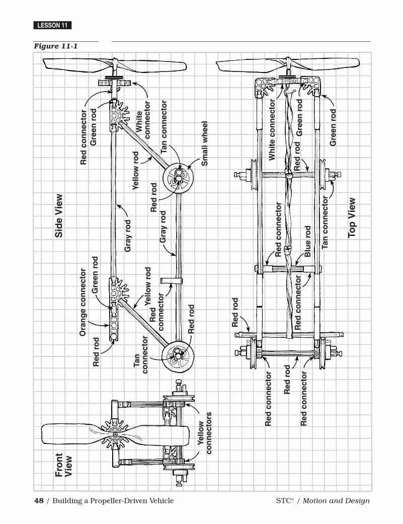
Figure 11-1
Sid
e V
iew
Gra
y ro
d
Gra
y ro
dRed
ro
dYello
w r
od
Yello
w r
od
Red
ro
d
Red
ro
d
Red
ro
dG
reen
ro
d
Ora
ng
e co
nn
ecto
r
Tan
con
nec
tor
Red
co
nn
ecto
rG
reen
ro
d
Red
con
nec
tor
Tan
co
nn
ecto
r
Wh
ite
con
nec
tor
Gre
en r
od
Gre
en r
od
Red
ro
d
Wh
ite
con
nec
tor
Red
co
nn
ecto
r
Blu
e ro
dR
ed c
on
nec
tor
Tan
co
nn
ecto
r
Red
ro
d
Red
co
nn
ecto
r
Red
co
nn
ecto
r
Top
Vie
w
Fro
nt
Vie
w
Yello
wco
nn
ecto
rsS
mal
l wh
eel