CHANGE Deliverable 2.3 revised -...
42
© CHANGE Consortium 2011 Page 1 of (42) ICT-257422 CHANGE CHANGE: Enabling Innovation in the Internet Architecture through Flexible Flow-Processing Extensions Specific Targeted Research Project FP7 ICT Objective 1.1 – The Network of the Future D2.3 Scenarios and Requirements – final revised version Due date of deliverable: 30 September 2011 Actual submission date of revised version: 09 December 2011 Start date of project: October 1st 2010 Duration: 36 months Lead contractor for this deliverable: Deutsche Telekom AG Confidentiality status: Public
Transcript of CHANGE Deliverable 2.3 revised -...
© CHANGE Consortium 2011 Page 1 of (42)
ICT-257422
CHANGE
CHANGE: Enabling Innovation in the Internet Architecture through Flexible Flow-Processing Extensions
Specific Targeted Research Project
FP7 ICT Objective 1.1 – The Network of the Future
D2.3 Scenarios and Requirements – final revised version
Due date of deliverable: 30 September 2011
Actual submission date of revised version: 09 December 2011
Start date of project: October 1st 2010 Duration: 36 months
Lead contractor for this deliverable: Deutsche Telekom AG
Confidentiality status: Public
D2.3 Scenarios and Requirements – final revised version
Page 2 of (42) © CHANGE Consortium 2011
Abstract
This report details a wide range of possible deployment scenarios and use cases for the flow pro-cessing technology developed within the project. From these, a set of requirements for the platform, the protocols and mechanisms has been generalized. This serves as a basis for the developments within the other work packages. Also it will be used as input on the choice of sample applications which will be implemented to demonstrate the technology.
The goal of this report is to ensure that the technology being developed is grounded in the demands of real networks, their operators and users.
Target audience
For the project participants this document describes a wide set of possible use cases which will be en-abled by a Flowstream platform. These scenarios may also be interesting as a general overview of po-tential capabilities for other experts in this area. It is an important internal milestone and the basis for future activities in the other work packages of CHANGE.
The readers are expected to be familiar with network technologies and architectures in general.
Disclaimer
This document contains material, which is the copyright of certain CHANGE consortium parties and may not be reproduced or copied without permission. All CHANGE consortium parties have agreed to the full publication of this document. The commercial use of any information contained in this docu-ment may require a license from the proprietor of that information.
Neither the CHANGE consortium as a whole, nor a certain party of the CHANGE consortium war-rants that the information contained in this document is capable of use, or that use of the information is free from risk, and accepts no liability for loss or damage suffered by any person using this infor-mation.
This document does not represent the opinion of the European Community, and the European Com-munity is not responsible for any use that might be made of its content.
Imprint
Full project title: CHANGE: Enabling Innovation in the Internet Architecture through Flexible Flow-Processing Extensions
Title of the work package: Scenarios, Requirements, and Architecture
Document title: D2.3, Scenarios and Requirements – final revised version
Editor: Peter Feil, Deutsche Telekom AG
Work package leader: Mark Handley, University College London
Project co-ordinator: Ádám Kapovits, Eurescom
Technical manager: Felipe Huici, NEC
This project is co-funded by the European Union through the ICT programme under FP7.
Copyright notice
© 2011 Participants in project CHANGE

D2.3 Scenarios and Requirements – final revised version
© CHANGE Consortium 2011 Page 3 of (42)
Executive Summary
The CHANGE project introduces a common concept of a flow processing platform instantiated at crit-ical points in the network. Based on modular components this Flowstream architecture is supposed to be programmable, allowing the network to evolve and support the needs of new applications. The key concept consists of “in-network” processing elements, which make it possible to perform specific ac-tions on dedicated communication flows in the network, and a network substrate which is able to han-dle individual data flows on different granularity levels.
After a short explanation of such a Flowstream architecture a wide range of possible use cases and deployment scenarios are listed. All of them are briefly described together with a summary of the ben-efits and the major requirements on the network.
Finally from all these scenarios a uniform set of primitive requirements that can then be used as the basis for designing and implementing the CHANGE architecture and platforms have been derived.
These findings will be used as input for further activities in the other work packages of the CHANGE project.
This is the final deliverable of the project concerning use case scenarios and requirements. Following some recommendations from the reviewers of the project this final revised version has slightly been modified compared to the version published in October 2011, in particular more figures have been added to better illustrate the individual use cases.

D2.3 Scenarios and Requirements – final revised version
Page 4 of (42) © CHANGE Consortium 2011
List of Authors
Gregory Detal, Université Catholique de Louvain
Peter Feil, Deutsche Telekom AG
Xin Huang, Deutsche Telekom AG
Paul Weissmann, Deutsche Telekom AG
Adam Greenhalgh, University College London
Mark Handley, University College London
Felipe Huici, NEC Europe Ltd.
Laurent Mathy, Lancaster University
Costin Raiciu, Universitatea Politehnica Bucuresti
Francesco Salvestrini, Nextworks
Steve Uhlig, Technical University of Berlin

D2.3 Scenarios and Requirements – final revised version
© CHANGE Consortium 2011 Page 5 of (42)
Table of contents
Executive Summary .............................................................................................................................. 3
List of Authors ....................................................................................................................................... 4
Table of contents .................................................................................................................................... 5
Abbreviations ......................................................................................................................................... 7
Table of figures ...................................................................................................................................... 9
1 Introduction ................................................................................................................................. 10
2 Scenarios and Use Cases ............................................................................................................. 12
2.1 Organisation-based (O) ......................................................................................................... 13
2.1.1 Virtual ISP (O1) ............................................................................................................ 13
2.1.2 Content Distribution Networks (O2) ............................................................................. 14
2.1.3 Follow-the-Sun Data Centres (O3) ................................................................................ 15
2.2 Network-based (N) ................................................................................................................ 16
2.2.1 Shadow Networks (N1) ................................................................................................. 16
2.2.2 Experimentation (N2) .................................................................................................... 17
2.2.3 Technology Migration and Deployment (N3) ............................................................... 18
2.2.4 Network Partitioning and Resource Allocation (N4) .................................................... 19
2.2.5 Network and Link Load Balancing (N5) ....................................................................... 19
2.2.6 Load Balancing and Path Selection within Data Centres (N6) ..................................... 20
2.2.7 Lawful Intercept (N7) .................................................................................................... 21
2.2.8 Network Substrate for Data Centres (N8) ..................................................................... 22
2.2.9 Hardware Accelerated Software Routers (N9) .............................................................. 24
2.3 Service-based (S) ................................................................................................................... 26
2.3.1 Network as a Service (S1) ............................................................................................. 26
2.3.2 In-Network Service-on-Demand (S2) ........................................................................... 27
2.3.3 Application/VM Migration (S3) .................................................................................... 27
2.3.4 Shippable Attack Mitigation (S4) .................................................................................. 28
2.3.5 Distributed IDS (S5) ...................................................................................................... 29
2.3.6 Distributed Firewall/Policy Enforcement (S6) .............................................................. 31
2.3.7 Middle Box Aggregation (S7) ....................................................................................... 31
2.3.8 Network Admission Control (S8) .................................................................................. 33
2.3.9 Deep Packet Inspection (S9) ......................................................................................... 33
2.4 Protocol (P) ........................................................................................................................... 34
2.4.1 Flow Monitoring (P1) .................................................................................................... 34
2.5 Scenario Selection and Other Deliverables ........................................................................... 35
3 Requirements ............................................................................................................................... 36
3.1 Architecture Requirements .................................................................................................... 36
3.1.1 Platform and Path Discovery ......................................................................................... 36
3.1.2 Flow State Management ................................................................................................ 37
3.1.3 Flow Re-routing ............................................................................................................ 37
3.1.4 Flow Definition ............................................................................................................. 37
3.1.5 Flow Ownership ............................................................................................................ 37
3.1.6 Management .................................................................................................................. 38
3.2 Platform Requirements .......................................................................................................... 38
3.2.1 Unit of Processing ......................................................................................................... 38

D2.3 Scenarios and Requirements – final revised version
Page 6 of (42) © CHANGE Consortium 2011
3.2.2 Isolation ......................................................................................................................... 39
3.2.3 Flow Migration .............................................................................................................. 39
3.2.4 Performance Scalability................................................................................................. 39
3.2.5 Flow Processing ............................................................................................................ 39
3.2.6 Standardized Interface ................................................................................................... 39
3.2.7 Interface to Routing ....................................................................................................... 39
3.2.8 Storage ........................................................................................................................... 39
3.2.9 Statistics Reporting ........................................................................................................ 40
3.2.10 Resource Management .................................................................................................. 40
3.2.11 Billing ............................................................................................................................ 40
4 Next Steps and Outlook .............................................................................................................. 41
References ............................................................................................................................................ 42

D2.3 Scenarios and Requirements – final revised version
© CHANGE Consortium 2011 Page 7 of (42)
Abbreviations
ACL Access Control List
AJAX Asynchronous JavaScript and XML
BGP Border Gateway Protocol
CAPEX Capital Expenditure
CDN Content Distribution Networks
CPU Central Processing Unit
DC Data Centre
DDoS Distributed Denial-of-Service
DHCP Dynamic Host Configuration Protocol
DNS Domain Name System
DPI Deep Packet Inspection
GFS Global File System
GUI Graphic User Interface
IDS Intrusion Detection System
IP Internet Protocol
IPv6 Internet Protocol version 6
IPTV Internet Protocol Television
ISP Internet Service Provider
MPLS Multi-Protocol Label Switching
NAC Network Admission Control
NAT Network Address Translation
OPEX Operational Expenditure
OSPF Open Shortest Path First
PC Personal Computer
POP Point Of Presence
PPP Point-to-Point Protocol
QoS Quality of Service
RADIUS Remote Authentication Dial In User Service
SLA Service Level Agreement

D2.3 Scenarios and Requirements – final revised version
Page 8 of (42) © CHANGE Consortium 2011
SQL Structured Query Language
URL Uniform Resource Locator
WP Work Package
VM Virtual Machine
VN Virtual Network
VPN Virtual Private Network

D2.3 Scenarios and Requirements – final revised version
© CHANGE Consortium 2011 Page 9 of (42)
Table of figures
Figure 1: Overview of a Flowstream Platform ...................................................................................... 11
Figure 2: Virtual ISP schema (O1) ........................................................................................................ 13
Figure 3: Shadow networks (N1) .......................................................................................................... 17
Figure 4: Experimental infrastructures (N2) ......................................................................................... 18
Figure 5: Monitoring Load Balancing (N6) .......................................................................................... 20
Figure 6: Network substrate for data centers ......................................................................................... 23
Figure 7: Hardware-accelerated Routers (N9) ...................................................................................... 25
Figure 8: Virtual network service (S1) .................................................................................................. 26
Figure 9: Virtual network as an on-demand network service (S2) ........................................................ 27
Figure 10: In-network DdoS attack mitigation (S4) .............................................................................. 29
Figure 11: Flowstream middleboxes architecture (S7) ......................................................................... 32
Figure 12: Flow monitoring (P1) ........................................................................................................... 34

D2.3 Scenarios and Requirements – final revised version
Page 10 of (42) © CHANGE Consortium 2011
1 Introduction
The Internet has grown over the last twenty years to a point where it plays a crucial role in today’s so-ciety and business. By almost every measure, the Internet is a great success. It interconnects over a billion people, running a wide range of applications, with new ones appearing regularly that take the world by storm. Yet despite this success the Internet comes with important shortcomings because it has originally not been designed for this wide range of usage scenarios.
During the last years the network research community has debated a number of new mechanisms and architectures for the Future Internet, both evolutionary and revolutionary, including ideas how to build the Internet completely new from scratch. Many interesting concepts have been developed but the main question remained: How should the new architecture of the Future Internet look like?
If we like it or not, there is no way back to the original end-to-end transparent Internet architecture from the beginning. There are just too many reasons why processing of data flows needs to be per-formed within the network, not just in the end-systems. To enable innovation we have to combine the strengths of both packet-switching and flow processing, rather than being religiously in one direction or another. We fundamentally believe in the advantages of a packet-switched Internet. What is missing are the primitives to introduce flow-processing at selected key points in the network. This flow pro-cessing needs to be done not as implicit hacks, but in a way that makes it a first class object in the network. If done right, we believe this will allow operators and application developers to reason about the emergent behaviour of the end-to-end path through such a network.
The CHANGE project is focussing on such a new network architecture which will provide an enabling platform to rapidly define and implement such new functionalities. We call the places where pro-cessing in the network takes place Flowstream flow processing platforms (or Flowstream for short).
In such a Flowstream platform (see figure 1), an OpenFlow switch is used to distribute incoming flows to various module hosts (essentially x86 servers). The module hosts contain a number of virtual ma-chines called processing modules where the actual network processing takes place. Any type of soft-ware package running on these modules can be used to process flows; a good candidate, for instance, is the Click modular router because of its flexibility and good performance. It is also worth pointing out that if needed, it is entirely possible to include a specialized hardware device (e.g., a DPI box) in a Flowstream platform. After the flows have been processed by the processing modules, the switch is once again used to send them back out of the platform. Naturally, it might not always be necessary to send flows out; for instance, if Flowstream is being used to monitor mirrored flows the processing modules will act as sinks.

D2.3 Scenarios and Requirements – final revised version
© CHANGE Consortium 2011 Page 11 of (42)
Figure 1: Overview of a Flowstream Platform
Flowstream also contains a controller which manages the entire platform. Such a controller can be lo-cated on a separate server as shown in the figure but could also run on one of the module hosts. The controller is in charge, among other things, of receiving allocation requests (or allocation for short) and allocating resources on the platform to them. This includes tasks like creating processing modules and instantiating the right type of processing in them, installing entries in the switch so that flows ar-rive at the appropriate processing modules, and monitoring the performance of the allocations. To help in the process each of the module hosts contains a control module that monitors the performance of a particular server and takes care of managing virtual machines, interfaces and other resources.
The following sections of this document describe scenarios and use cases which could be enabled by such a Flowstream platform.

D2.3 Scenarios and Requirements – final revised version
Page 12 of (42) © CHANGE Consortium 2011
2 Scenarios and Use Cases
This chapter lists various use cases and scenarios brought up in discussions so far that might be ena-bled by a Flowstream platform. The scenarios are categorized, depending on where they might be im-plemented: Organisation-based, Network-based, Service-based, and Protocol-based.
# Name Use case/benefit
Organisation-based Scenarios
O1 Virtual ISP Virtual topologies on top of any substrate, spanning across ISPs
O2 Content-Distribution Networks Building CDNs without having to own physical infrastructure, can place CDN nodes at convenient location in the network
O3 Follow-the-Sun Data Centres Optimal usage of resources by moving VMs around DCs
Network-based Scenarios
N1 Shadow Networks Debugging and testing in parallel to production on live networks
N2 Experimentation Experiments on real-world production networks
N3 Technology Migration and Deployment Parallel/virtual deployment of new technologies into existing substrates
N4 Network Partitioning and Resource Allocation
Light-weight MPLS-like provisioning
N5 Network and Link Load Balancing Dynamic traffic engineering and shaping
N6 Load Balancing and Path Selection within Data Centres
Better usage of network resources in DCs
N7 Lawful Intercept Exploit flow-processing to mitigate the need of specialized equipment
N8 Network Substrate for Data Centres An “opened network framework" for Data Centres to allow network-aware service workflows with high flexibility, increased systems perfor-mances, reduced CAPEX/OPEX, openness to innovation flows
N9 Hardware-accelerated Software Routers Commodity-based flexible software routers
Service-based Scenarios
S1 Network as a Service Provisioning of virtualised circuits/networks on existing substrates
S2 In-Network Service-on-Demand Dynamic VPNs for customers/services
S3 Application/VM migration Move VMs/services closer to customers, without needing middle-boxes
S4 Shippable Attack Mitigation Filtering attacks close to their sources, for instance to counter DdoS
S5 Distributed IDS IDS capabilities spread throughout a network, without middle-boxes
S6 Distributed Firewall/Policy Enforcer Centralised, network-wide packet filtering and policy enforcement
S7 Middle-box Aggregation Easier maintenance and setup, more competition in applications
S8 Network Admission Control NAC without the need for specialized NAC protocols
S9 Deep Packet Inspection DPI without specialized middle-boxes
Protocol-based Scenarios
P1 Flow Monitoring More transparency through OpenFlow processing framework

D2.3 Scenarios and Requirements – final revised version
© CHANGE Consortium 2011 Page 13 of (42)
2.1 Organisation-based (O)
2.1.1 Virtual ISP (O1)
There are many ways to build a "Virtual ISP" using flow processing platforms. The simplest scenario we have discussed is where a network (network A) has a "home" network but wishes to extend its reach to a remote location. At the remote location, another ISP (network B) maintains a flow pro-cessing platform. Network A contracts with network B for access to one or more nodes on B's flow processing platform. B agrees to accept BGP routes from A at the flow processing platform, and to advertise them to B's peers/customers. This redirects traffic destined to A into the flow processing platform, where A's flow processing agent first sees the traffic. This traffic is then tunnelled back to a flow processing platform at A's network.
Why would an ISP do this? The main reason could be that A does not wish to forward all the traffic directly back to its home network. For example:
• A DDoS filter needs to run on the traffic to filter some unwanted traffic close to its origin. Simi-larly, the ISP might want to apply firewall rules close to the sources of traffic.
• Some of the traffic can be served by CDN software running on the Flowstream platform (see Scenario: CDN).
• Some of the traffic needs to be redirected to another site than it was originally destined to.
• The ISP wishes to route traffic differently from what it can achieve using native BGP destina-tion-based forwarding.
• The ISP might want to provide an encrypted tunnel from mobile clients on network B where en-cryption is crucial but too expensive or battery-draining to perform on the local device.
Outgoing traffic from network A could also be forwarded via the flow processing platform into net-work B, assuming A's contract with B permits this.
It is also possible to envisage a Virtual ISP that does not possess a single internally-connected net-work, but instead has multiple POPs that interconnect using tunnelling between flow processing plat-forms carried over third-party networks. In many cases this would not be economical - the third parties are likely to charge too much to make such services profitable. But for niche or special service ISPs, this would allow them to operate in a very flexible manner, as long as their business model is not just selling a bit pipe.
Virtual Network Provider
(VNP)
Physical Infrastructure Providers (InP)
Virtual Network Operator
(VNO)
End users
Service Provider
(SP)
Figure 2: Virtual ISP schema (O1) - Here split into separate VNPs and VNOs [P1956]
Benefits
The Flowstream technology would enable the required programmability of networking devices from different ISPs with their own backbone.

D2.3 Scenarios and Requirements – final revised version
Page 14 of (42) © CHANGE Consortium 2011
For corporate customers having different geographic locations, distributed Internet access could be provided cheaper than using common ISP offerings.
Internet access and in-network services could be made available that are not provided by a single ISP.
Requirements
The proposed “Virtual ISP” scenario imposes many requirements on the underlying platform and the network management framework/tools built on top.
Requirements to the platform:
• First, the network platform (at least the flow processing platform of network B) must support network virtualization. That is, multiple “virtual network” slices should be able to share the same physical platform without interfering with each other. This in turn requires the resource isolation on the physical network systems, e.g., routing table isolation, ACL isolation, etc.
• To facilitate traffic redirection, the network platform should support a well-defined communica-tion protocol (e.g., OpenFlow) that enables network programmability features including, but not limited to, flexible flow definition, dynamic flow re-routing, and line-rate packet header modifi-cation.
• To facilitate wide-area traffic redirection, the network platform should support a well-defined interface to IP routing, allowing traffic to be drawn to a processing module from the external In-ternet.
Requirements to the network management framework/tools:
• The network management framework should support dynamic resource management. For ex-ample, it should be able to identify and monitor available network resources (e.g., nodes, links, processing resources, etc.). It should be able to dynamically allocate resources when a VN slice is created and dynamically release the resources when a VN slice is deleted.
• The network management framework should be able to monitor the network resources used by each VN slice.
• Furthermore, the network management framework should provide a toolset for the renters to manage (e.g., configure, check status, reconfigure, etc.) their slices in real-time.
• Finally, advanced management mechanisms could be embedded within the management frame-work to optimize network performance or resource utilization.
2.1.2 Content Distribution Networks (O2)
A CDN or a site hosting data wishes to distribute some fraction of the requested data from a location closer to the clients. To do this, the site contracts with a remote flow processing platform inside an ISP located at or near to the intended clients.
Client traffic must be forwarded to the flow processing platform. This can be done in two ways: The host of the flow processing platform accepts routes from the CDN so as to forward traffic destined to the CDN agent to the flow processing platform. Alternatively, the DNS resolver, typically located within the ISP network of the client, redirects the DNS requests from the client to the flow processing platform, which then acts as an authoritative DNS server. Also, the authoritative DNS resolver of the CDN or hosting site can perform DNS redirection so that traffic from the client will be directed to the flow processing platform.
In addition, the flow processing platform can be used to gather usage statistics about the content it is hosting (e.g. how many hits a particular file is getting, or where the hits are coming from). Such meas-urements can then be used as input to a cache replacement strategy. In particular, the data could be

D2.3 Scenarios and Requirements – final revised version
© CHANGE Consortium 2011 Page 15 of (42)
used by a content popularity prediction algorithm to decide in advance where (i.e. at which flow pro-cessing platform) to install the content. The overall goal here is to improve the performance of content retrieval: lowering bandwidth cost while reducing response delay or download time.
Benefits
There are several reasons why a site might wish to purchase such capability. For example, positioning content closer to the consumers reduces bandwidth cost. Furthermore, flow processing platforms can be dynamically contracted to serve content, providing a way to expand or contract a service or busi-ness on-demand. Intelligent content placement can also reduce latency, decreasing completion times for "transactions" such as AJAX apps. Also, hiring out platforms on demand allows smaller content delivery companies to compete with big players like Akamai. Such big players have their own large, distributed delivery infrastructure, so it is hard for a small player to compete against them since that would require the deployment of lots of platforms close to potential content consumers. Instead, smaller players would rent resources from flow processing platforms where and when needed, making the content delivery market more competitive.
So far we have discussed the benefits from the customer’s point of view (i.e., the entity renting the platform's capabilities). From the platform owner’s point of view (for example an operator or ISP), the advantages of allowing edge sites to run CDN capabilities include an additional revenue stream, better usage of the ISP's data centre (if the ISP owns one), and reduced bandwidth cost (since traffic no long-er transits through the ISP from its upstream provider).
Requirements
The scenario has the following requirements with respect to the flow processing platform:
• Platforms must have storage capability.
• Platforms must give processing modules (the slices in platforms) access to its corresponding storage slices.
• Platforms must be able to dynamically insert/remove CDN processing modules.
• Platforms must be able to dynamically insert/remove storage slices.
• Platforms must support content isolation and processing module isolation (i.e., a content deliv-ery company should not have access to another company's content).
• Platforms must be able to collect per-content statistics, and give CDN processing modules ac-cess to them.
• Platforms should support a well-defined API, allowing routes to be advertised to the Internet, permitting traffic to be drawn to the processing module.
In addition, the CHANGE architecture should be able to
• Help content providers/distributors to locate suitable flow processing platforms. This includes finding platforms closer to content consumers, as well as advertising platforms' capabilities (in terms of storage, current load, etc.).
2.1.3 Follow-the-Sun Data Centres (O3)
Large content providers such as Google and Amazon typically have multiple geographically-distributed data centres. Load-balancing across these data centres is done by DNS or URL rewriting (e.g. Akamai). Load-balancing within a data centre is done by network system virtualization. Virtual machines are dynamically created, deleted and migrated between different physical machines, which allows better utilization of the resources available in the data centre.
D2.3 Scenarios and Requirements – final revised version
Page 16 of (42) © CHANGE Consortium 2011
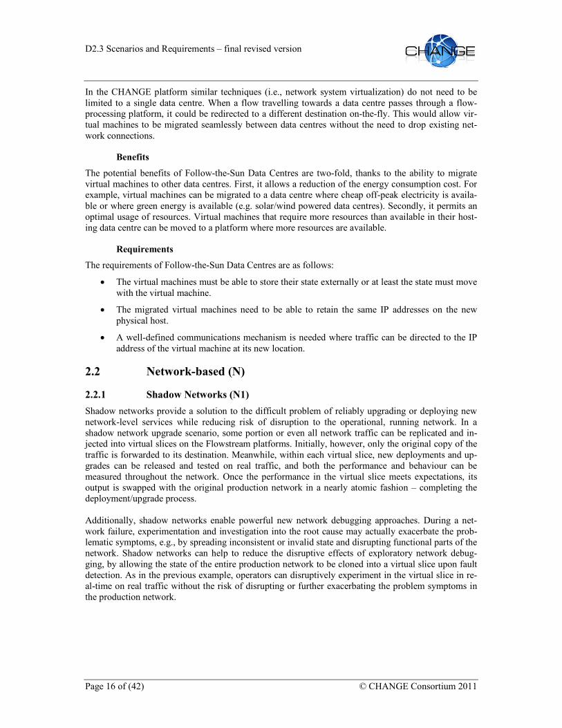
In the CHANGE platform similar techniques (i.e., network system virtualization) do not need to be limited to a single data centre. When a flow travelling towards a data centre passes through a flow-processing platform, it could be redirected to a different destination on-the-fly. This would allow vir-tual machines to be migrated seamlessly between data centres without the need to drop existing net-work connections.
Benefits
The potential benefits of Follow-the-Sun Data Centres are two-fold, thanks to the ability to migrate virtual machines to other data centres. First, it allows a reduction of the energy consumption cost. For example, virtual machines can be migrated to a data centre where cheap off-peak electricity is availa-ble or where green energy is available (e.g. solar/wind powered data centres). Secondly, it permits an optimal usage of resources. Virtual machines that require more resources than available in their host-ing data centre can be moved to a platform where more resources are available.
Requirements
The requirements of Follow-the-Sun Data Centres are as follows:
• The virtual machines must be able to store their state externally or at least the state must move with the virtual machine.
• The migrated virtual machines need to be able to retain the same IP addresses on the new physical host.
• A well-defined communications mechanism is needed where traffic can be directed to the IP address of the virtual machine at its new location.
2.2 Network-based (N)
2.2.1 Shadow Networks (N1)
Shadow networks provide a solution to the difficult problem of reliably upgrading or deploying new network-level services while reducing risk of disruption to the operational, running network. In a shadow network upgrade scenario, some portion or even all network traffic can be replicated and in-jected into virtual slices on the Flowstream platforms. Initially, however, only the original copy of the traffic is forwarded to its destination. Meanwhile, within each virtual slice, new deployments and up-grades can be released and tested on real traffic, and both the performance and behaviour can be measured throughout the network. Once the performance in the virtual slice meets expectations, its output is swapped with the original production network in a nearly atomic fashion – completing the deployment/upgrade process. Additionally, shadow networks enable powerful new network debugging approaches. During a net-work failure, experimentation and investigation into the root cause may actually exacerbate the prob-lematic symptoms, e.g., by spreading inconsistent or invalid state and disrupting functional parts of the network. Shadow networks can help to reduce the disruptive effects of exploratory network debug-ging, by allowing the state of the entire production network to be cloned into a virtual slice upon fault detection. As in the previous example, operators can disruptively experiment in the virtual slice in re-al-time on real traffic without the risk of disrupting or further exacerbating the problem symptoms in the production network.

D2.3 Scenarios and Requirements – final revised version
© CHANGE Consortium 2011 Page 17 of (42)
Figure 3: Shadow networks (N1)
Benefits
• Ease of deployments and upgrades in running networks, and safely revert or atomically commit.
• Enable isolated testing and debugging environments.
• Improved robustness to failures, as state checkpoints in virtual slices allow rollbacks during faults and failures.
• No middle boxes/external replicators needed.
• Smoother integration of technologies due to replication and use of live traffic.
• Higher network availability thanks to the debugging potential of shadow networks.
• Reduced CAPEX/OPEX by not needing to run separate test networks.
Requirements
Shadow networks rely on a Flowstream platform which must support: • Programmable packet forwarding hardware with arbitrary granularity flow definition (e.g. abil-ity to match packets and forward flows according to any combination of layer 2 to layer 4 head-er fields).
• The ability to define and redefine flow definitions (i.e. per-flow forwarding state) such that eve-ry packet within the network has a consistent forwarding policy applied.
• Ability to replicate/multiply any incoming traffic to an arbitrarily number of output ports at line-rate per defined flow.
• Strict per-flow bandwidth and resource isolation and QoS enforcement.
• Accurate per-flow traffic measurement and statistics reporting.
2.2.2 Experimentation (N2)
Debugging operational networks is often a daunting task, and sometimes requires a complete replica of the original environment, which is hardly feasible for current networks. The ability to use the pro-duction network as the experimentation platform would allow operators to reproduce software errors, data-path limitations, or configuration errors. An interesting scenario for network operators is the use of flow processing platforms and OpenFlow for running experiments and tests on the production net-work infrastructure while not interfering with the production traffic. This would be facilitated through the use of network virtualization on the network substrate, allowing the same infrastructure devices to be used in a virtualized way for both production traffic and experimentation. Flow processing plat-

D2.3 Scenarios and Requirements – final revised version
Page 18 of (42) © CHANGE Consortium 2011
forms would enable this virtualization and isolation by using resource (processing/CPU) and interface-level bandwidth virtualization on the network devices. Operators might use this solution to experiment with the impact of new technologies and protocols on real-world hardware and networks and gain rel-evant experience on production systems. Coupled with Scenario N1 to select and replay specific traf-fic, testing and debugging of operational networks would be possible.
Not only network operators but also researchers might be interested in using a large-scale network as an experimentation platform, to test newly designed/developed protocols, services, and applications. This is in some sense similar to the "virtual ISP" scenario but the requirements in terms of resources are not so strict, something like a downgraded version of the "virtual ISP" service.
Figure 4: Experimental infrastructures (N2)
Benefits
This scenario extends the possible usage of existing network capacities and improves debugging and testing capabilities.
Requirements
Using Flowstream platforms for experimentation requires thorough isolation, security and resource management features.
2.2.3 Technology Migration and Deployment (N3)
Network operators might use flow processing platforms to migrate and deploy new network protocols, services and technologies into their networks.
With network virtualisation made possible through flow processing platforms running OpenFlow, the operators can introduce disruptive technologies on small, well-defined islands while sharing the same infrastructure for the current production traffic.
One example is the deployment of new routing protocols (new versions of BGP) in the backbone, which only affects a selected set of customers, or the phased rollout of new network protocols such as IPv6.
These small islands with new technologies might be extended depending on deployment success, fi-nally incorporating the whole subset of users and customers. In case of problems or failure, the new technology might be scaled back quickly without affecting the other parts of the network.
Flow processing platforms enable the necessary virtualisation on the network device level.
D2.3 Scenarios and Requirements – final revised version
© CHANGE Consortium 2011 Page 19 of (42)
Benefits
This use case makes it possible to test on live, production hardware and not on an isolated testbed.
Requirements
Technology migration using Flowstream-based networking platforms requires the devices to be able to provide resource isolation, security isolation and maybe host-based virtualisation also at the router level.
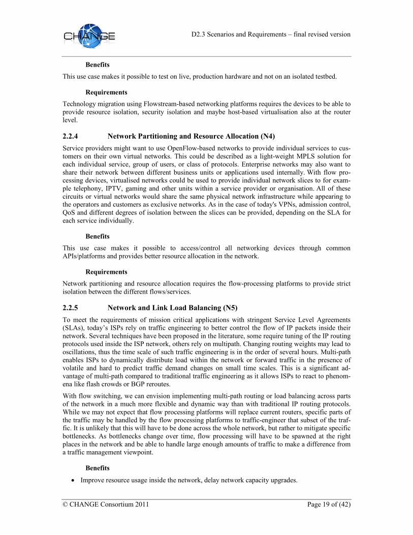
2.2.4 Network Partitioning and Resource Allocation (N4)
Service providers might want to use OpenFlow-based networks to provide individual services to cus-tomers on their own virtual networks. This could be described as a light-weight MPLS solution for each individual service, group of users, or class of protocols. Enterprise networks may also want to share their network between different business units or applications used internally. With flow pro-cessing devices, virtualised networks could be used to provide individual network slices to for exam-ple telephony, IPTV, gaming and other units within a service provider or organisation. All of these circuits or virtual networks would share the same physical network infrastructure while appearing to the operators and customers as exclusive networks. As in the case of today's VPNs, admission control, QoS and different degrees of isolation between the slices can be provided, depending on the SLA for each service individually.
Benefits
This use case makes it possible to access/control all networking devices through common APIs/platforms and provides better resource allocation in the network.
Requirements
Network partitioning and resource allocation requires the flow-processing platforms to provide strict isolation between the different flows/services.
2.2.5 Network and Link Load Balancing (N5)
To meet the requirements of mission critical applications with stringent Service Level Agreements (SLAs), today’s ISPs rely on traffic engineering to better control the flow of IP packets inside their network. Several techniques have been proposed in the literature, some require tuning of the IP routing protocols used inside the ISP network, others rely on multipath. Changing routing weights may lead to oscillations, thus the time scale of such traffic engineering is in the order of several hours. Multi-path enables ISPs to dynamically distribute load within the network or forward traffic in the presence of volatile and hard to predict traffic demand changes on small time scales. This is a significant ad-vantage of multi-path compared to traditional traffic engineering as it allows ISPs to react to phenom-ena like flash crowds or BGP reroutes.
With flow switching, we can envision implementing multi-path routing or load balancing across parts of the network in a much more flexible and dynamic way than with traditional IP routing protocols. While we may not expect that flow processing platforms will replace current routers, specific parts of the traffic may be handled by the flow processing platforms to traffic-engineer that subset of the traf-fic. It is unlikely that this will have to be done across the whole network, but rather to mitigate specific bottlenecks. As bottlenecks change over time, flow processing will have to be spawned at the right places in the network and be able to handle large enough amounts of traffic to make a difference from a traffic management viewpoint.
Benefits
• Improve resource usage inside the network, delay network capacity upgrades.

D2.3 Scenarios and Requirements – final revised version
Page 20 of (42) © CHANGE Consortium 2011
• Reduce CAPEX by delaying network upgrades.
• More flexible and faster traffic engineering.
Requirements
The ability of the flow processing platforms to handle high packet forwarding rates is needed for this use case. The platforms must also be capable of interacting with the native packet forwarding in the network to direct the traffic of a flow over a specific path. This requires that either the network runs OpenFlow, it runs MPLS in a similar way to switch traffic to a path, or that some other way to redirect traffic (such as tunnelling) is used.
2.2.6 Load Balancing and Path Selection within Data Centres (N6)
Load balancing plays a key role in many networks. It allows improving the performance and the scalability of the Internet by distributing the load evenly, or according to a certain policy, across net-work links, servers or other resources.
With a flow-processing platform an efficient usage of the network capacity by the computing re-sources (servers) in data centres and the Internet access devices can be achieved without specialised load balancing hardware. A flow-processing element can be used to balance the flow over multiple possible forwarding paths towards the destination while ensuring that all packets belonging to the same transport flow follow the same route to avoid packet reordering.
Figure 5: Monitoring Load Balancing (N6)
Benefits
The potential benefits of load balancing and path selection within data centres is a better usage of the available network resources thus avoiding congestion and achieving redundant connectivity. By using load balancing and path selection within data centres there is no need for specialised load-balancing equipment/middle boxes.
Requirements
The main requirement of load balancing and path selection within data centres is the availability of an efficient load balancing mechanism (whether at switch or processing element level). There should also be a signalling mechanism that enables to discover the various available paths between a source and the destination within the platform.
D2.3 Scenarios and Requirements – final revised version
© CHANGE Consortium 2011 Page 21 of (42)
2.2.7 Lawful Intercept (N7)
Almost every country has an individual legal framework regarding the support required from operators for lawful intercept. In this scenario we aim to explore how flow processing concepts and the in-network processing functions embodied in the CHANGE framework can facilitate lawful intercept.
Lawful intercept requires that operators are able to intercept a flow of data, filter it and redirect or copy it to an interception device.
The interception device could be an offsite relay, local storage, a binary black box image for pro-cessing, or a physical black box.
CHANGE's proposed inclusion of flow identification, filtering and in-network processing is very well suited to the functions of lawful intercept. With CHANGE the filtering functions that previously would have occurred using dedicated hardware can be replaced by the generic flow identification, fil-tering and manipulation, thus reducing cost of hardware and operations. One way to practically achieve this would be the use of OpenFlow. A central OpenFlow controller from the network operator could be used to accept the lawful intercept requirements, possibly handing them off to a secondary OpenFlow control whose role is to give the interception agency more control over the precise filtering rules.
CHANGE's second focus of an in-network flow processing platform is also well suited for lawful in-tercept. The ability for an interception agency to provide a black box software entity rather than a physical piece of hardware allows to scale across multiple machines in a flow processing platform and also to reduce the CAPEX and OPEX.
Lawful interception brings with it a number of security and privacy concerns that are not always obvi-ous. For example the end users being intercepted should be unable to discover that they are being in-tercepted. This requires that additional signalling and control traffic is not exposed to the end systems, and that end systems are not able to query for the existence of interception flow processing hardware on the path of their traffic nor that they are able to control it.
A less obvious requirement is that the presence of filtering and interception rules on the operator’s sys-tems should be limited to those people with adequate authorisation.
Benefits
The benefits of CHANGE to lawful intercept are the ability to exploit the generic flow processing and in-network processing provided by CHANGE to reduce the requirements for costly specialised hard-ware in the network to undertake the required functions whilst simplifying the operational issues. This reduces the cost for the network operators and hence for their customers.
Requirements
The requirements for lawful intercept are that traffic from or to a particular location can be:
• Specified,
• Filtered and/or dropped,
• Redirected or copied to a location for processing,
• Users should be unaware of the interception taking place,
• The interception rules cannot be changed or seen except by those authorised to do so.
A number of processing models need to be supported depending on legal requirements, with all of the-se having the correct levels of security and authorisation in place.

D2.3 Scenarios and Requirements – final revised version
Page 22 of (42) © CHANGE Consortium 2011
• Local storage,
• Relay to offsite,
• Virtual black box processing,
• Dedicated black box processing.
2.2.8 Network Substrate for Data Centres (N8)
The proliferation of advanced services for virtualisation, cloud computing, social networks, etc. has significantly boosted the demand for storage, computation power and bandwidth/QoS in the Data Cen-tres (DCs). However, the integration and management of the ever-increasing number of network de-vices have become more and more complex and costly due to either the use of proprietary solutions or the integration of a number of different service and network components in a highly fragmented, silo-like approach.
Large-scale Internet DCs such as Amazon, Google and Microsoft host tens of thousands of servers providing online services to millions of users distributed across the Internet. To cope with this scale, to increase efficiency and to lower the total cost of ownership these DCs use customed solutions for both software and hardware:
• Software services such as distributed file systems and databases are implemented as custom ser-vices, e.g. BigTable, Map-Reduce, Dryad, Dynamo, Chubby and GFS only to name a few.
• Hardware customisation for servers, racks and power supplies is a common practice, as the scale of the DCs makes it economically feasible to design and build dedicated hardware.
Small-scale DCs are often more locked-in with vendor’s bundle solutions for hardware, supervision software and networking, due to their reduced capabilities for large investments in proprietary solu-tions. Nevertheless, these bundled off-the-shelf solutions, like the Cisco-VMware based virtual net-working infrastructure, often provide many (and maybe not primarily) functionalities to the DC ad-ministrators, as they need to support the many different customer requirements and deployment sce-narios. Subsequently, there is a high impact on the flexibility of the operated platforms with an over-dimensioning of the systems (in terms of provided vs. actually used features), and also on the CAPEX/OPEX of the infrastructure.
The core internetworking principle for which endpoints treat the IP network as an always connected best-effort black box can be surely considered not optimal for DCs. In fact, DC networks have specific features very different from the Internet general use-case and rationales, for example:
• Many DC services need to dynamically form logical network topologies on top of the physical one, while the network does not offer sufficient openness, e.g. direct access and manipulation of L2/L3 functionalities for traffic profiling and routing;
• A DC network topology is well-known and commonly ad-hoc (e.g. hierarchical, fat-tree, hyper-cube);
• The number of nodes can be high but always limited (from tens to hundreds) and custom-routing is mostly used to improve performance compared to what standard IP routing protocols can provide;
• Security is an issue mainly at the external interfaces (i.e. for remote users’ accesses) but it is not so critical in the DC core due to implicit server to server trust relationships;
• Full control of physical environment data (e.g. power dissipation and consumption, temperature, etc.) is a key requirement to implement flexible and effective system load and/or management policies.

D2.3 Scenarios and Requirements – final revised version
© CHANGE Consortium 2011 Page 23 of (42)
As a general and common requirement for both large and small-scale DCs, the availability of a more open, customizable and controllable networking substrate can allow to integrate the provisioning of the underlying network connectivity services into the overall service workflows. This new approach would allow to overcome the current “always on network pipe” assumption, which is often the main reason for degraded DC service performances.
Flow processing based network devices might be deployed in DCs to have a closer integration of net-working and computing substrates. The full programmability of the network substrate would allow a very tight coupling of the computing and networking platforms to form a more integrated system.
A programmable network substrate offers the opportunity to address the aforementioned issues, above all for intra-DC services. Computing resources might control the network substrate directly and thus directly manage their traffic flows, the related network rules for QoS, etc. This in-depth network pro-grammability can allow exposing networks to the application layer and allows services to adapt to and fully exploit the topology.
An open network programming interface would even open up a world of integration, automation and management to be service-driven that would otherwise be difficult to achieve. For example, a service could be implemented directly upon the API provided by the networking substrate, or could use both , the API and information provided by other services, supporting a layered approach. The network sub-strate could also allow to reduce IT network operation complexity and expenses through the automa-tion, management and monitoring of the DC network portion. Functional management areas (configu-ration, provisioning, inventory, monitor, fault and troubleshooting) could be driven by applications, working in a unified and coherent view of the network.
Figure 6: Network substrate for data centers
Benefits
• Higher system flexibility and increased performance due to an open network "framework". This includes better automation and dynamic resource management, directly driven by applications.
• Reduced OPEX/CAPEX by using open and commodity platforms instead of proprietary ones
• Reduced setup and maintenance costs, simplified and unified administration.

D2.3 Scenarios and Requirements – final revised version
Page 24 of (42) © CHANGE Consortium 2011
• More openness to further software/network integration cycles, which implies more rapid inno-vation and adaptation as technology improves.
Requirements
Conceptually the network substrate should provide the DC with a programmable option to implement large-scale distributed services. The network substrate APIs should expose most of, if not all, the net-work facilities in a way that is programmatically simple, reliable and flexible. The more open, simple and robust these APIs are, the easier it will be to integrate current and future products.
In summary, the requirements on the network substrate implied by this use case are:
• Allow DC services to send packets directly to a neighbour on a set of specified links, or to broadcast packets to a set of selected neighbours (routing should be custom defined by the DC itself).
• Expose network facilities and topology (multicast/broadcast capabilities, current topology lay-outs, network resources states and availability, etc.).
• Provide network related events notifications (failure or maintenance events for links/switches).
• Allow to activate/deactivate links (for power saving).
• Services should be able to intercept, modify and drop packets at each hop.
2.2.9 Hardware Accelerated Software Routers (N9)
Open-source software is already deployed within enterprise and ISP networks for specialized tasks. Its quality is approaching what is commonly referred to as “carrier grade”. However, PC-based routers with open-source routing software do not offer the throughput, port density, and/or reliability needed for ISPs’ purposes. On the other hand, Ethernet switches often provide layer-3 functionalities and con-tain components, e.g., TCAMs, for performing longest prefix matching at line rate and offer multiple-terabit throughput.
In this scenario we leverage the decoupling of traditional tasks of a router, i.e. maintaining up-to-date routing information and forwarding packets. We propose an alternative router design that couples a commodity PC running an open-source software router with lower cost programmable switching hardware. Such switches usually have very limited FIB memory, not enough to keep a complete Inter-net routing table of more than 300k entries. We are using the switch as a flexible forwarding engine for high-performance forwarding for most of the traffic. The PC acts as a route controller and further-more handles the traffic that is chosen not to be forwarded by the switch. Our scenario is based on an OpenFlow-enabled switch, and a Linux-PC running the open source routing suite Quagga. An Open-Flow controller serves as the glue logic connecting Quagga and the switch.
The programmable switch serves as our fast path, the PC as our route controller. The architecture re-lies on a communication channel and alternative forwarding path (slow path) between the switch and the PC, maintained by our controller “RouteVisor”.

D2.3 Scenarios and Requirements – final revised version
© CHANGE Consortium 2011 Page 25 of (42)
Figure 7: Hardware-accelerated Routers (N9)
Components of the system:
• Programmable switch: Crucial for the design is the availability of an advanced switch control interface, such as OpenFlow, for modifying FIB contents as well as for retrieving traffic statis-tics.
• RouteVisor: The main tasks of RouteVisor include 1) allowing Quagga to operate on physical switch ports as if they were local interfaces, 2) monitoring routing table updates by Quagga, 3) maintaining traffic statistics, and 4) populating the FIB of the switch with the most popular des-tination prefixes. Although we rely on Quagga for our prototype, any other Linux software rout-er should work as a plug-in replacement, since no source code modifications to Quagga are nec-essary.
• FIBpredict: Is the prefix selection strategy designed to keep most traffic on the fast path while minimizing FIB churn and making it hard for an attacker to target the slow path. To keep most of the traffic on the fast path we rely on the Zipf-like property of destination popularity in Inter-net traffic and use past traffic statistics to predict upcoming popular prefixes. To keep churn low we rely on long-term trends, and to ensure flexibility and short reaction times, e.g., in case of traffic changes or DoS attacks, we also include recently popular prefixes.
• Forwarding: As we are constrained by limited FIB memory on the switch, we introduce a fast path and a slow path for packet forwarding. If a packet matches a prefix as present in the switch FIB, the switch can forward the packet on its own, we call this our fast path. The OpenFlow switch takes care of rewriting the MAC addresses, and the OpenFlow 1.1 release introduces support for decrementing IP TTL. If the destination of a packet is unknown to the switch FIB, it is directed towards the PC via the VLAN trunk. The PC learns about the packet’s ingress port by inspecting the VLAN identifier. Then, Linux determines the appropriate egress interface based on its local routing table as maintained by Quagga. Finally, after rewriting the layer-2 header and decrementing the IP TTL value, the packet is sent back to the switch where it is then forwarded to the appropriate network interface based on the VLAN identifier.
(Taken from FIBIUM/Nadi Sarrar’s 2010 SIGCOMM students workshop 2-pager.)

D2.3 Scenarios and Requirements – final revised version
Page 26 of (42) © CHANGE Consortium 2011
Benefits
This approach has the potential to bring the flexibility of software routers into previously unexplored contexts, such as data centres and aggregation networks.
Requirements
Programmable switch with the following features: • API for insertion and deletion of flow table entries (FIB entries)
• API for retrieval of flow statistics i.e., packets or byte counters, in a fine-grained manner, e.g., every n seconds.
• Layer 3 forwarding
2.3 Service-based (S)
2.3.1 Network as a Service (S1)
Programmable network platforms such as OpenFlow could enable dynamic network provisioning and thus allow (re)configuration of networks as a service.
Operators could offer solutions such as virtual links, virtual networks (VPNs) and virtual circuits on-the-fly as a service without the need for complex operator-side provisioning, such as in MPLS or cus-tomer-side network device configurations.
Since programmable network devices make networks inherently virtualisable, this could lead to simple implementation of network-as-a-service concepts and hence lowering the OPEX of virtual networks.
The programmable flow processing platforms needs to be able to correctly allocate and split the avail-able computing and link resources and provide sufficient security (isolation).
Figure 8: Virtual network service (S1)
Benefits
• No need for complex VPN/tunnelling protocols,
• Easy reconfiguration through software-defined networks.
Requirements

D2.3 Scenarios and Requirements – final revised version
© CHANGE Consortium 2011 Page 27 of (42)
Network-as-a-service-based scenario using Flowstream platforms need to implement a minimum level of security/isolation, provide bandwidth guarantees and a method for customer network management access.
2.3.2 In-Network Service-on-Demand (S2)
This scenario envisages the use of programmable OpenFlow network platforms to implement services on-demand for customers in their networks or on their links. The flow processing platforms in an op-erator’s network would enable dynamic and on-demand provisioning of services onto existing (virtual) networks and active links. OpenFlow-based networks would make the necessary dynamic network reconfiguration easily possible.
There are multiple scenarios possible for either re-sellers (or Virtual ISPs) and operators. Most would centre on the provisioning of network services to either own Internet customers or those from other Internet access providers, which would be interested in acquiring the given service onto their own In-ternet link. Examples include:
• Sell firewall services to third parties, either end-users or other service providers with the provi-sioning of a "firewall factory" in a business model similar to Amazon EC2,
• Buy an IDS as a network service "onto" your internet access pipe – traffic from participating us-ers gets screened by a central IDS system in the operator's or the provider’s network. This could also be outsourced to third-party vendors,
• Add virus checking of your data streams onto your internet access pipe.
Data centre /
Cloud provider
Fixed
Network
Internet /
Managed IP
3G/4G/WiFi
/Femto
Access network
e.g. IP/ADSL
Smartphone
e.g. iPad
PC
Optical
User – Cloud access
and devices
Multiple networks
Many providers
Virtual network
Figure 9: Virtual network as an on-demand network service (S2) [P1956]
Benefits
No overlay networks or separate protocols are needed (tunnels, mobile IP, etc.).
Requirements
The scenario in-network services on-demand requires for provider/network-spanning setups a stand-ardised interface to the network devices so these services could be interoperable over different do-mains.
2.3.3 Application/VM Migration (S3)
The goal for a service provider is to move applications (services) and VMs (servers) in a virtualised network nearer towards the internet edge where the user access is coming from.

D2.3 Scenarios and Requirements – final revised version
Page 28 of (42) © CHANGE Consortium 2011
With a farm of servers near internet access nodes (or PoPs) the provider could use flow processing platforms to move service VMs in the network in real time to the server farms next to the PoPs where the majority of traffic occurs.
Fully virtualised network substrates would allow the dynamic reallocation and migration of applica-tions depending on the network load.
This is similar to the Follow the sun (O3) scenario (data centre mobility).
However, in some cases, moving application/processes/VMs may be an onerous proposition, simply because of the sheer amount of data (e.g. machine image, process address space, video library, etc) to be moved. This is especially true when the associated network flows exhibit a traffic volume of the same order of magnitude of the data being moved, or smaller.
In such cases, moving particular flows, as opposed to whole services/VMs, would be more efficient. Indeed, by only moving the state relative to specific flows, the migration process would be much more efficient and much less disruptive to the network as a whole and its services. Furthermore, such a flow migration primitive would provide a highly flexible mechanism to realize flexible, fine-grained and dynamic traffic engineering and load balancing, both essential to high-efficient, agile networks.
Benefits
No middle boxes are needed for this scenario.
The flow migration primitive elevates the notion of flow to the rank of first class citizen. The notion of flow is essential to almost any reasoning about the semantics of network services and applications, and flow migration is a fundamental primitive in the construction of flow-aware programmable networks.
Requirements
Flow migration requires a unified way to represent flow state, as well as flow state semantics, across applications and services. This encompasses both new programming models to allow the programmer to convey flow state information, as well as run-time mechanisms to represent, find and migrate live flow state.
2.3.4 Shippable Attack Mitigation (S4)
The presence of malicious traffic is commonplace in today's Internet, despite of constant efforts to combat it. In some cases, such as with Distributed Denial-of-Service attacks, such traffic can cause significant network disruption and monetary losses. One of the main reasons that render these sorts of attacks difficult to stop is that, while identifying which traffic to filter may be relatively simple, being able to place filters at the right places in the network is unfeasible in today's Internet.
In a typical attack, a number of distributed malicious sources, typically belonging to a botnet, generate large amounts of traffic that aggregate towards a victim. Clearly the destination has a clear incentive to filter the traffic, and so they do; however, at that point in the network the malicious traffic has often aggregated to such an extent that it is difficult to filter at the source (even the uplink of the victim's access provider can be saturated). Ideally, filtering should happen close to the sources of the malicious traffic, but unfortunately the current Internet does not provide mechanisms to install filters based on location. Even worse, providers sourcing malicious traffic do not have clear incentives to install such filters: Such traffic is not necessarily disrupting their local networks and there is no way for victims to pay for such filtering service.
D2.3 Scenarios and Requirements – final revised version
© CHANGE Consortium 2011 Page 29 of (42)
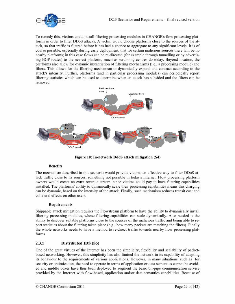
To remedy this, victims could install filtering processing modules in CHANGE's flow processing plat-forms in order to filter DDoS attacks. A victim would choose platforms close to the sources of the at-tack, so that traffic is filtered before it has had a chance to aggregate to any significant levels. It is of course possible, especially during early deployment, that for certain malicious sources there will be no nearby platforms; in this case flows can be re-directed (for example through tunnelling or by advertis-ing BGP routes) to the nearest platform, much as scrubbing centres do today. Beyond location, the platforms also allow for dynamic instantiation of filtering mechanisms (i.e., a processing module) and filters. This allows for the filtering mechanism to dynamically expand and contract according to the attack's intensity. Further, platforms (and in particular processing modules) can periodically report filtering statistics which can be used to determine when an attack has subsided and the filters can be removed.
Figure 10: In-network DdoS attack mitigation (S4)
Benefits
The mechanism described in this scenario would provide victims an effective way to filter DDoS at-tack traffic close to its sources, something not possible in today's Internet. Flow processing platform owners would create an extra revenue stream, since victims could pay to have filtering capabilities installed. The platforms' ability to dynamically scale their processing capabilities means this charging can be dynamic, based on the intensity of the attack. Finally, such mechanism reduces transit cost and collateral effects on other users.
Requirements
Shippable attack mitigation requires the Flowstream platform to have the ability to dynamically install filtering processing modules, whose filtering capabilities can scale dynamically. Also needed is the ability to discover suitable platforms close to the sources of the malicious traffic and being able to re-port statistics about the filtering taken place (e.g., how many packets are matching the filters). Finally the whole networks needs to have a method to re-direct traffic towards nearby flow processing plat-forms.
2.3.5 Distributed IDS (S5)
One of the great virtues of the Internet has been the simplicity, flexibility and scalability of packet-based networking. However, this simplicity has also limited the network in its capability of adapting its behaviour to the requirements of various applications. However, in many situations, such as for security or optimization, the need to operate in terms of application or data semantics cannot be avoid-ed and middle boxes have thus been deployed to augment the basic bit-pipe communication service provided by the Internet with flow-based, application and/or data semantics capabilities. Because of

D2.3 Scenarios and Requirements – final revised version
Page 30 of (42) © CHANGE Consortium 2011
the complex nature of the task to be undertaken, middle boxes have traditionally provided a special-ized functionality which, although sometimes built using custom hardware, has typically not scaled to the fastest link speeds. As a consequence of this, middle boxes of all sorts have proliferated at the edge of the network. This deployment at the network edge is far from ideal, as it offers little resource shar-ing opportunity between middle boxes offering the same service. Take for instance two IDS systems deployed at different entry points to a same network: One might be overloaded with traffic, while the other may only be moderately loaded; currently, re-balancing the load of the middle boxes (e.g. IDS boxes) would require the use of complex traffic engineering measures to re-balance the traffic volume between these boxes. Likewise, because of the often specialized nature of a middle box, unused mid-dle box resources cannot easily be repurposed for other forms of processing.
One approach to address these shortcomings would be to deploy middle boxes functionality in data-centre style facilities. While this affords sharing and repurposing of computing power, this approach does however require that traffic be diverted to such processing centres, thus not only changing the natural flow of traffic across the network but also concentrating this traffic near the processing facility, generating stringent and potentially very expensive bandwidth requirements. Moreover, such an ap-proach would not serve middle box processing that must necessarily be executed in proximity of, or on the physical path between, the communicating end-points. This is true, for example, of applications such as WAN optimizers, traffic measurement, filtering-based DDoS protection, encryption or data-loss protection engines (since the path from the edge to the data centre would be unsecured), and so forth.
The CHANGE network architecture, on the other hand, provides a natural way to spread processing power more evenly across (i.e. within) the network. We can thus assume that every router in a network has some processing capability. Note, however, that this is only a simplifying assumption: the system proposed here is easily adapted to more incremental deployment scenarios by considering that the reg-ular routers in the network simply form links between the enhanced routers (i.e. CHANGE processing platforms). We do not make any assumption about the amount of processing power an enhanced router has for middle box functionality: This processing power may well be insufficient to process all the traffic the router receives.
In this context, the key question is what subset of flows a router should process so that the network as a whole can maximize its processing output. Said differently, what subset of flows should a router leave to be processed downstream by spare processing capacity in other routers? This question should be formulated as an optimization problem in order to find an answer based on firm theoretical grounds.
While this formulation would provide an optimal solution to the problem of distributed flow pro-cessing, it is not directly applicable in the practical context of a network. Indeed, to reach the optimal solution, the exact state of the network must be known. This is clearly impossible in a real network. For instance, a router can, at best, only estimate the size of a flow on arrival of the first packet of that flow. Several methods should therefore be proposed that can be deployed practically within a network, while yielding a global flow processing output that approaches the theoretical solution.
Benefits
• No middle-boxes needed or generic system complementing existing middle boxes,
• Fewer expenses due to results of attacks,
• Reduced OPEX due to less attack network traffic,
• Reduced OPEX/CAPEX due to not having to run separate middle-boxes,
• Reduced OPEX/CAPEX due to more efficient use of resources (better output from equivalent processing power than when all processing is concentrated at the edge of the network).

D2.3 Scenarios and Requirements – final revised version
© CHANGE Consortium 2011 Page 31 of (42)
Requirements
In order to implement a distributed IDS with flow processing platforms, global (on-line) optimization methods (centralized or distributed) for networks are needed. For the selection of traffic further ad-vanced hashing methods for aggregate/implicit flow selection are needed to avoid flow entry explo-sion in classification devices. To implement the distributed setup of the IDS flow migration capabili-ties are needed.
2.3.6 Distributed Firewall/Policy Enforcement (S6)
With OpenFlow networks distributed network policy and filtering (firewalling) enforcement is made possible on all levels of the network. All network access, filtering and forwarding rules (or policies) would be managed on a central system in this scenario, which in turn would forward these "rules" to the network controllers. OpenFlow is a very attractive choice for building such a framework since (in general) all flows have to be checked by the central controller anyway, which would allow this con-troller to write "rules" to all attached network devices.
One very simple example would be to prohibit all SQL network traffic in a given enterprise network. Depending on the actual implementation, the controller could instruct the switch(es) to drop any sub-sequent packets in an SQL flow after it was first forwarded to the controller. It would also be possible for the controller to proactively write rules out to the network devices to drop all SQL traffic. Imple-menting this kind of network policies with a flow processing architecture would alleviate the need for specialised filtering devices on the network edges and allow filtering throughout the network at all levels/devices.
A more complex example could be a large organisation that has a complex network structure that re-quires a large number of specialised rules. By using a mix of course grain rules on a large number of OpenFlow switches to direct traffic towards a smaller set of switches where the detailed rules can ap-plied, enables the firewall policy to scale further.
The CHANGE architecture enables further scaling and processing with the introduction of the flow processing platform where additional filtering capabilities and capture can be deployed as required.
Benefits
• No middle-boxes needed,
• Centralised control,
• Reduced OPEX/CAPEX due to not having to run separate appliances/middle boxes,
• Reduced OPEX due to unwanted traffic being filtered as close to the source as possible and not traversing the network.
Requirements
Distributed firewall and policy enforcements need the ability to dynamically install filtering pro-cessing modules, whose filtering capabilities can scale dynamically. To find the closest available or suitable firewalling system the ability is needed to discover suitable platforms close to the filtering location. Statistics need to be reported about the filtering taken place (e.g., how many packets are matching the filters). After selection of the closest platform the firewall solution needs the ability to re-direct traffic towards nearby flow processing platforms. Filtering rules need to be able to be subdi-vided and make them specific to locations.
2.3.7 Middle Box Aggregation (S7)
There has been a steady rise in the number of middle boxes deployed by ISPs worldwide to enhance the functionality or optimise the performance of today's communication protocols. Examples include

D2.3 Scenarios and Requirements – final revised version
Page 32 of (42) © CHANGE Consortium 2011
traffic shapers, intrusion detection systems, firewalls, traffic normalisers, performance enhancing proxies, and so forth. All of these middle boxes are deployed because they do useful things for particu-lar applications. They are typically black-boxes sold by vendors to solve a specific problem. They have well defined performance characteristics and limited scaling. When a device cannot cope with the load, it is usually replaced with a newer generation device with more performance.
The trouble with middle boxes is that they optimise the network for today's traffic at the expense of tomorrow's traffic. Once deployed, they are difficult to upgrade or change. Typically, they are just re-placed when obsolete. Not only this is expensive, but it means that ISPs are stuck with a certain type of processing for a long time. Furthermore, each middle box behaves like a black-box, has its own set of configuration parameters, and its processing cannot be easily chained with other middle boxes to produce an enhanced service. Because of this black-box behaviour, the semantics of a chain of middle boxes processing the same traffic are often undefined or misunderstood.
CHANGE is an opportunity to evolve from this state of affairs. The basic building blocks of CHANGE - the flow-processing platform, the unified definition of flow and intra platform signalling - allows us to replace these middle boxes with software counterparts, or at the very least to make them adhere to predefined semantics.
CHANGE will run middle box functionality mostly on x86 hardware, with OpenFlow directing traffic between processing modules, as in the Flowstream platform. This decouples hardware and software for middle box processing. Its main effect is to allow quick deployment of new processing, quicker upgrades to existing processing, and seamless scaling capabilities.
Further, CHANGE's unified definition of flows and platform interoperation will allow processing ele-ments to speak the same language, which will in turn allow operators to reason about the effects of composing different functionalities.
Figure 11: Flowstream middleboxes architecture (S7)

D2.3 Scenarios and Requirements – final revised version
© CHANGE Consortium 2011 Page 33 of (42)
Benefits
The main benefit will be lower setup and maintenance costs (hardware is not replaced when pro-cessing changes, or when load grows), easier administration. Moving to a software market for pro-cessing will allow new players to enter the middle box market, increasing competitiveness.
Requirements
A common definition of flow and processing types is needed throughout all the involved devices and services. Further basic ways to compose processing and reason about expected outcomes are required.
2.3.8 Network Admission Control (S8)
Network Admission Control (NAC) is an access control solution that is enabled on network devices (such as DHCP servers, firewall, switches, etc.) to force a user or a machine to authenticate in the sys-tem prior the granting access to the network.
Programmable flow-processing network inherently could replace existing, external NAC solutions, which depend on forwarding authentication traffic towards centralised system with specialised proto-cols. The ability to program and completely control the network (edge and access) devices would make at least the separate NAC protocols such as 802.1X or solutions such as RADIUS redundant, since much of the functionality could be replicated with e.g., modules in the central network control-lers.
The same holds true for Internet access network, where the separate PPP infrastructure could be sim-plified with the help of flow processing platforms.
Benefits
With Network Admission Control there is no need to purchase and deploy NAC protocols. There is no need for separate NAC protocols.
Requirements
Network Admission Control requires that a signalling methods exists between the client and the flow-processing platform that allows to: (1) configure the control that is needed; (2) list the authorised us-ers; (3) retrieve information about the current authenticate users.
Network Admission Control also requires that all traffic that needs to be controlled to go through the processing-platform.
2.3.9 Deep Packet Inspection (S9)
Network devices based on flow processing platforms could make deep packet inspection in a network much easier and remove the need for specialised DPI devices. Currently specialised platforms and middle boxes are used to inspect traffic within different places of a network according to specified rules.
Traffic patterns, specific protocols or sources/destinations can be selected easily with OpenFlow-based networks to be specially handled at the network devices and then re-routed to specific analy-sis/archival systems or directly processed and analyzed at the controller. With the addition of payload or protocol decoders the central controller could either directly inspect higher-level protocols or ex-tract the relevant information or payload for external analysis.
Flow processing devices make it easier to both select and forward individual and groups of flows for later analysis, since all (or most) traffic decisions are to be handed over initially to the central control-lers, where selection and forwarding/mirroring could be done. DPI would not need to be handled by specialised middle boxes but could be added as an optional feature to the central network control backplane.

D2.3 Scenarios and Requirements – final revised version
Page 34 of (42) © CHANGE Consortium 2011
Benefits
• No middle-boxes needed, no complex traffic mirroring/redirection needed,
• Reduced CAPEX/OPEX due to not having to run specialised DPI boxes,
• Reduced OPEX due to less DPI-related traffic in the network.
Requirements
Required are possible protocol decoders for deep inspection of payload protocols in case all possible higher-level protocols need to be inspected. Dynamic configurability is required to tune the DPI sys-tem to evolving needs. Since the inspection process might be heavily CPU-bound, a way for offload-ing this from the actual selection system might be needed. In order to inspect large amounts of patterns in the flow space pattern-matching/wildcarding for flow/table entries in hardware is needed.
2.4 Protocol (P)
2.4.1 Flow Monitoring (P1)
It is very difficult to tell what went wrong when a connection stops working today, as the network is not transparent: If a middle box fails or denies connectivity, there is no real way for the user to tell what and where the problem is. Major outages are typically discovered and corrected by the operators, but failures can be subtle and can affect only a small part of the traffic. For instance, the behaviour of various middle boxes varies wildly when new TCP options are used, or when new TCP flags are used.
CHANGE can expose the statistics about the flows it processes; these statistics will either be stored for all traffic, or on demand from the user. These statistics include number of packets processed per moni-toring period, processing applied and so forth, and are statistics maintained by the processing plat-forms anyway.
The source and destinations of each flow, or other authorised parties, can enquire flow processing plat-forms on the route of the flow about flow state. By correlating this information across different pro-cessing platforms, the user can figure out where the problem resides.
Figure 12: Flow monitoring (P1)

D2.3 Scenarios and Requirements – final revised version
© CHANGE Consortium 2011 Page 35 of (42)
Benefits
A framework for flow monitoring will increase network transparency and robustness. Problems will be identified much quicker, reducing downtimes for end-users. Also, this will provide basic support for accountability:
• Reduced OPEX due to better traceability of problems,
• Reduced CAPEX due to not having to use separate network filtering/traffic inspection devices (Like Fluke etc.).
Requirements
A common definition of flow and processing types is needed, as well as the definition of flow owner-ship and an extensible language to define flow statistics, and a query language to interrogate them.
2.5 Scenario Selection and Other Deliverables
The scenarios listed in this deliverable will be used by D5.1 to select scenarios deemed useful from the partners for later implementation and deployment.
The process, which will be described in more detail in deliverable D5.1, is as follows:
• A set of criteria will be selected with which the scenarios will be weighed.
• Each partner assigns values to the criteria for each scenario and states preferences.
• The scenarios will be selected based on partner feedback, priorities and other comments.
We aim to have a small set of scenarios that will be of use for actual applications in deployed CHANGE platforms.

D2.3 Scenarios and Requirements – final revised version
Page 36 of (42) © CHANGE Consortium 2011
3 Requirements
Even though the use cases presented in this document cover a wide range of fields and applications, many of the requirements that they place on the CHANGE architecture (WP4) and the flow processing platforms (WP3) are common. The purpose of this section is, consequently, to collate these into a uni-form set of primitive requirements that can then be used as the basis for designing and implementing the CHANGE architecture and platforms. The rest of this section explains such requirements, split by those that apply to the CHANGE architecture and by those that apply only to the flow processing plat-forms.
3.1 Architecture Requirements
In this section we address requirements related to the CHANGE architecture, essentially the wide-area network scenario where multiple flow processing platforms are deployed at different locations of a large network such as the Internet; this equates to the work described in WP4. The requirements on the architecture are as follows:
3.1.1 Platform and Path Discovery
Before any processing can take place, a user, where a user is taken to be a person or entity owning a set of flows and wanting the architecture to process them in a certain way, needs to be able to discover information about flow processing platforms (or platforms for short) in the network. The type of in-formation can be roughly broken down into two types. First, users should be able to discover the loca-tion of platforms. Such information can be used to choose platforms close or on-path with respect to a flow that needs processing in order to minimize the disruption to the flow's normal path. Another use would be to ensure that processing is taking place close to the sources of traffic, as in the case of the shippable filtering use case.
An open question is to what extent the user needs to be able to specify location to instantiate pro-cessing. If the user specifically requires processing to take place at a certain topological or geographic location, then either the user needs to be able to find a platform and communicate with it to instantiate processing, or else the user needs to be able to request processing at a specific location and any plat-form satisfying the specified location could respond.
However, a user may not care about the specific location, but rather care that processing take place "on the path" between a specific source and destination, whatever that path may currently be. Broadly speaking, the requirements do not dictate a separate phase of locating the platform, then instantiating processing on that platform. Rather it may be preferable to request processing with a set of constraints on the location that performs this processing; any platform satisfying those constraints could then "bid" to perform the processing. Having separate location and instantiation phases may be simpler, but avoiding the need to understand location might be more flexible.
In addition to specifying location, a further possibility would be to discover neighbouring platforms close to a specific one, in case the latter needs to offload some work. Again, this specification of loca-tion could be performed in a separate location phase, prior to instantiation, or as a combined loca-tion/instantiation phase.
The second type of information has to do with capabilities. Each platform should be able to express what sort of processing it is able to handle (e.g., in terms of available CPU power, memory, storage, etc), and the architecture should be able to expose this. Revealing the actual capabilities of a flow-processing platform is likely to be commercially sensitive. Rather that revealing capabilities directly, it may be more desirable to simply request processing that matches a processing description, and the platform then state whether it can provide the processing requested (and at what price, if the transac-tion is between different organizations).
D2.3 Scenarios and Requirements – final revised version
© CHANGE Consortium 2011 Page 37 of (42)
Any capability description language needs to be future proof, and as separated from the underlying technology as possible. The capability description language (whether it describes platforms or a user's processing requirements) must be future-proof in the sense that it should be capable of outliving the current envisaged generation of platforms.
While this provides primitives that allow users to configure processing as well as the path that flows take through platforms, ultimately it may be the architecture that takes care of asking users for high-level requirements (e.g., filter DDoS traffic coming from a set of sources), and translating those into which platforms to use, which processing to instantiate, and how to direct flows to them. This will be especially true if processing must take place on a very large number of platforms.
3.1.2 Flow State Management
In the project's vision, flows will be re-directed to the platforms that will process them. While we are only interested in doing this for flows that need special processing (many flows are content enough with the best-effort service provided by today's Internet), even this sub-set is likely to result in a signif-icant amount of flows and, as a result, present a challenge in terms of flow state management. For ex-ample, a re-direction point may need to contain large amounts of per-flow entries, as might also be the case with the platform themselves. The architecture should provide a mechanism for efficiently man-aging potentially large quantities of flow state.
3.1.3 Flow Re-routing
The architecture should provide the ability to dynamically re-route or re-direct flows to the appropriate flow processing platforms. In addition, it should be possible for such re-direction to be triggered by processing currently taking place in a platform. For instance, if a platform containing an IDS deter-mines that a flow is malicious, it should be able to re-direct it to a scrubbing centre (perhaps hosted at another platform). Ultimately, we expect that a common usage case is for a flow to be forwarded on to its original destination after being processed and re-routed. In other cases though, the flow would nev-er reach its original destination, either being terminated (for example, because it is hostile) or being served directly by a platform which was not the original destination, as indicated by IP. Both modes should be possible, subject to appropriate authentication and/or authorization.
In addition, it should be possible to Tee a flow, so that the flow reaches its destination, but a copy of the packets is also sent elsewhere. This may be necessary for lawful intercept or intrusion detection, but raises significant privacy issues.
3.1.4 Flow Definition
Fundamental to the flow handling discussed throughout this document is the definition of what a flow actually is. The architecture should provide such definition and ensure that such a definition is flexible enough to encompass a wide range of uses. Note that the typical definition of a flow as a set of tuples based on header fields is limiting; for instance, under this scheme, trying to define a flow based on how long it lasts or as all traffic in a multicast tree under this scheme is difficult at best.
3.1.5 Flow Ownership
The architecture needs to have a mechanism to determine, for a given flow or set of flows, who is al-lowed to process them / re-direct them. While the source of a flow is a clear candidate to be the owner of that flow, this is insufficient, as other entities should be allowed to process that flow (e.g., the source's ISP or law enforcement agencies). It seems that at the very least, the source, destination and networks traversed by a flow have ownership in some sense, though they should not necessarily all have the same capabilities to instantiate processing. The CHANGE architecture must address this issue of who should be authorized to instantiate different types of flow processing, so as to address privacy, security and network stability concerns.

D2.3 Scenarios and Requirements – final revised version
Page 38 of (42) © CHANGE Consortium 2011
3.1.6 Management
The architecture should provide flow management mechanisms for flow owners. This may include information such as which platforms flows are going through, performance statistics about the connec-tions between platforms, as well as statistics regarding how flows are being processed at the platforms. Management should include the ability to diagnose what processing is being performed on a flow, in part to ensure that it is possible to debug the network.
3.2 Platform Requirements
This section outlines the requirements for the individual flow processing platforms, essentially the work covered by WP3.
3.2.1 Unit of Processing
The processing of flows plays a central role in the CHANGE architecture. Indeed, one of the funda-mental principles of this architecture is that flows should become first-class citizens in what is nowa-days predominantly a packet-based communication medium.
In this context, identifying flows is a classification problem, which has received much attention from the research community and for which viable solutions exist both in hardware and software. The CHANGE flow processing platform can readily make use of such solutions within a hierarchical clas-sification structure, designed and set up to direct flows to their corresponding processing unit or mod-ule.
The processing of the flows themselves can cover a whole range of complexity. Simple flow pro-cessing can consist of little more than updating some state associated with the flow. For example, counting the bytes in a flow falls within this category. NAT and firewalling (stateful or not) can also be considered in this category: once the flow has been identified, the extra processing is minimal. The particularity of simple flow processing is that the notion of flow is mainly encapsulated by the classifi-cation itself, while the processing proper can easily be carried out on a per-packet basis. The CHANGE flow processing platform will support such simple flow processing efficiently, based on re-using and adapting existing packet-based systems such as Click.
However, more involved flow processing, such as anomaly detection, IDS, etc. The programmers of these flow processing applications can benefit from a flow abstraction that frees them from the intrica-cies of flow packetisation, allowing them to focus on manipulating the contents of a flow as a single logical entity. It is such abstraction that promotes flows to first-class citizen status in the flow pro-cessing system. While flow reconstruction (reassembling the "stream" of bytes belonging to a flow) is an important mechanism in building such a flow abstraction, doing so in a highly efficient manner is primordial.
Also, complex flow processing can be realized as a processing pipeline, where various processing module functionalities are applied to the flow. In this context, and depending on the functions applied, the interdependency of the various modules can be complex too: in a simple case, a strict succession can be enforced, where a module can only touch parts of a flow that has been completely treated by other modules preceding it in the processing pipeline; on the other hand, modules could "share" simul-taneous access to the flow content if their respective operations do not interfere with each other. Yet another example is that a module may mark portions of a flow to inform processing further down the complex flow processing pipeline. Isolation between various flows and their processing is also a prime concern.
As can be seen, the flow processing abstraction, while providing a programming model better suited to complex flow processing, introduces complex mechanisms that call for a highly efficient implementa-tion. The development of such an abstraction and its associated mechanisms is a main goal in CHANGE.

D2.3 Scenarios and Requirements – final revised version
© CHANGE Consortium 2011 Page 39 of (42)
3.2.2 Isolation
It is envisaged that a flow processing platform will perform processing on behalf of many users and many applications simultaneously. It is a requirement that different users of the platform are isolated from each other, both in terms of the data that can be observed (privacy), data that can be modified (integrity), and in terms of the impact of one user on the performance seen by other users.
3.2.3 Flow Migration
Several of the use cases require processing in terms of VMs to be migrated. While the platforms can certainly support this (VM migration is available from several virtualization technologies), migrating VMs may be an onerous proposition, simply because of the sheer amount of data (e.g., machine im-age, process address space, video library, etc) to be moved. Expensive migrations such as this will likely result in a sluggish architecture. A more efficient alternative would be moving particular flows instead of whole services/VMs.
By only moving the state relative to specific flows, the migration process would be much more effi-cient and much less disruptive to the network as a whole and its services.
3.2.4 Performance Scalability
A flow processing platform should be able to dynamically scale processing performance up or down based on current requirements and load. Such a mechanism could be achieved by concentrating pro-cessing onto as few machines as possible (scaling down) or by dynamically adding or turning on ma-chines when the demand ramps up.
3.2.5 Flow Processing
Flow processing platforms should allow for flexible flow processing. While this document describes a wide range of use cases, it is a certainty that we cannot envision how such platforms might be used in the future. Consequently, they should provide a means for creating and running new types of pro-cessing as the need arises. Further, the instantiating of such processing should be dynamic, and pro-cessing belonging to different owners should be isolated from each other.
3.2.6 Standardized Interface
CHANGE will not dictate exactly how a flow processing platform should be instantiated: such a plat-form could range from a single PC at one end, all the way to a data centre at the other. Instead, CHANGE will provide a common interface and requirements that all flow processing platforms need to adhere to.
3.2.7 Interface to Routing
Many uses of a flow processing platform require that traffic be drawn to the platform, rather than it passively observing the traffic passing by. This requires flow processing platforms to interact with conventional Internet routing protocols such as OSPF and BGP. Authorization for announcing routes into Internet routing protocols needs to be considered carefully.
3.2.8 Storage
Flow processing platforms should provide storage (though this may be an optional requirement such that only certain flows support this and advertise this fact when they announce their capabilities). In particular, they should support access to the content from the processing modules, including dynamic insertion and deletion of that content. Finally, the platform should ensure content isolation, making sure that only the owner of the content has access to it. The owner of the content is likely to be con-text-specific; it will certainly include the user who instantiated the flow processing module, but it might also include the source and/or destination of the traffic being processed.

D2.3 Scenarios and Requirements – final revised version
Page 40 of (42) © CHANGE Consortium 2011
3.2.9 Statistics Reporting
Platforms should be able to provide detailed statistics about the status of the processing taking place at any one point in time. Such reporting will have different granularities, going from platform-wide or per-PC statistics (important to owners / operators of platforms) down to per-processing or per-flow statistics (relevant to owners of flows).
3.2.10 Resource Management
Platforms should make efficient use of their available resources. This boils down to a resource man-agement problem, where the platforms need to map flows and processing to PCs. Fundamental to this is the ability to measure the cost that a flow imposes on a piece of hardware (such as a PC) as it is ac-tually being processed.
3.2.11 Billing
Many uses of flow processing platforms will require the instantiation of processing by one user on a platform owned and operated by another organization. While the platforms themselves do not need to incorporate a mechanism for billing, the overall architecture must consider this, and the platforms need to provide a sufficient audit trail that a user can verify that they received the service they paid for.

D2.3 Scenarios and Requirements – final revised version
© CHANGE Consortium 2011 Page 41 of (42)
4 Next Steps and Outlook
This is the second and final deliverable of the project concerning use case scenarios and requirements, superseding the deliverable D2.1 – Scenarios and requirements – early draft. It describes possible use cases and their implications on the architecture of the CHANGE platform. It is meant as input for fur-ther activities in other work packages of this project.
The requirements derived from the set of use cases will be used to define the components and their interactions that will form the architecture specification. An early draft of the architecture specification is already available (Deliverable 2.2), but a more elaborate final version will be produced in the com-ing months (Deliverable D2.4, due by the end of 2011).

D2.3 Scenarios and Requirements – final revised version
Page 42 of (42) © CHANGE Consortium 2011
References
[Amazon EC2] Amazon Elastic Compute Cloud: http://aws.amazon.com/ec2/
[BibTable] Fay Chang, Jeffrey Dean, Sanjay Ghemawat, Wilson C. Hsieh, Deborah A.Wallach, Mike Burrows, Tushar Chandra, Andrew Fikes, and Robert E. Gruber: Bigtable: A Distributed Storage System for Structured Data. OSDI'06: Seventh Symposium on Operating System Design and Implementation, Seattle, WA, November, 2006.
[CHANGE] http://www.change-project.eu/
[Chubby] Mike Burrows: The Chubby Lock Service for Loosely-Coupled Distributed Systems. OSDI'06: Seventh Symposium on Operating System Design and Implementation, Se-attle, WA, November, 2006.
[Dryad] Michael Isard, Mihai Budiu, Yuan Yu, Andrew Birrell, and Dennis Fetterly: Dryad: Distributed Data-Parallel Programs from Sequential Building Blocks. European Con-ference on Computer Systems (EuroSys), Lisbon, Portugal, March 21-23, 2007
[Dynamo] Giuseppe DeCandia, Deniz Hastorun, Madan Jampani, Gunavardhan Kakulapati, Avinash Lakshman, Alex Pilchin, Swaminathan Sivasubramanian, Peter Vosshall and Werner Vogels: Dynamo: Amazon’s Highly Available Key-value Store. SOSP 2007
[Flowstream] Adam Greenhalgh, Felipe Huici, Mickael Hoerdt, Panagiotis Papadimitriou, Mark Handley, Laurent Mathy: Flow processing and the rise of commodity network hard-ware. ACM SIGCOMM Computer Communication Review archive Volume 39 , Is-sue 2 (April 2009)
[GFS] Sanjay Ghemawat, Howard Gobioff, and Shun-Tak Leung: The Google File System. 19th ACM Symposium on Operating Systems Principles, Lake George, NY, October, 2003.
[MapReduce] Jeffrey Dean and Sanjay Ghemawat: MapReduce: Simplified Data Processing on large Clusters. OSDI'04: Sixth Symposium on Operating System Design and Imple-mentation, San Francisco, CA, December, 2004.
[MPLS] E. Rosen, A. Viswanathan, R. Callon: Multiprotocol Label Switching Architecture. RFC 3031, January 2001
[Normalization] M. Handley, C. Kreibich and V. Paxson: Network Intrusion Detection: Evasion, Traf-fic Normalization, and End-to-End Protocol Semantics. Proc. USENIX Security Symposium 2001
[OpenFlow1] http://www.openflow.org/
[OpenFlow2] Nick McKeown, Tom Anderson, Hari Balakrishnan, Guru Parulkar, Larry Peterson, Jennifer Rexford, Scott Shenker, and Jonathan Turn: OpenFlow: Enabling Innovation in Campus Networks. ACM CCR 2008
[P1956] Eurescom Study P1956 on Network Virtualisation – Opportunities and Challenges, deliverable D1, Network Virtualisation – opportunities and challenges for operators, December 2010
[PEPs] J. Border, M. Kojo, J. Griner, G. Montenegro, Z. Shelby: Performance Enhancing Proxies Intended to Mitigate Link-Related Degradations. RFC 3135, June 2001