Chameleon Installation & Maintanance
28
Chameleon –Crystal Laser series Laser Marking System Instruction Manual
Transcript of Chameleon Installation & Maintanance

Chameleon –Crystal Laser series Laser Marking System
Instruction Manual

Chameleon crystal Laser Marking System
Installation and maintenance manual
TABLE OF CONTENTS
Introduction .................................................................................................. 1
Safety ............................................................................................................. 2
Laser Safety ............................................................................................. 2
Safety Labels ............................................................................................ 3
Safety Warning Symbols and Definitions ................................................ 5
Packaging Contents ..................................................................................... 6
System Overview .......................................................................................... 7
Installation and Connection ........................................................................ 8
Installation................................................................................................ 8
Operating Environment ............................................................................ 8
Exhaust ..................................................................................................... 9
Connection ............................................................................................... 9
Operation ......................................................................................................13
Hardware driver installation ...................................................................13
Flow of Operation ....................................................................................13
Power ON/OFF ........................................................................................14
Recovery from Unexpected Shutdown ....................................................14
Setting the Focal Length of the Beam......................................................14
Operating the Controller ..........................................................................15
Functions on the Front Panel ...................................................................15
Maintenance .................................................................................................16
Cleaning ...................................................................................................17
Specifications and Dimensions ....................................................................19
Environmental/Operating Conditions ......................................................20
Marking Head Dimensions ......................................................................21
External I/O Connection .............................................................................22
Troubleshooting ...........................................................................................24
Warranty ......................................................................................................25

Chameleon crystal Laser Marking System
Installation and maintenance manual 1
Introduction
Thank you for purchasing the CHAMELEON Series Laser Marking System.
Please read and obtain a full understanding of this manual before installation and operation.
Please read the CDRH requirements under the Safety Section.

Chameleon crystal Laser Marking System
Installation and maintenance manual 2
Safety
Laser Safety
The Chameleon Series marking system contains a state-of-the-art diode-pumped solid-state
laser that produces intense and invisible laser radiation at a wavelength of 1064 nm in the
near infrared spectrum. The LE series is designed as a CLASS IV device. Improper use of
controls and adjustments or performance of procedures other than those specified in this
manual may result in hazardous exposure to the laser radiation.
Remember the following safety precautions when operating the laser system.
1. Exposure to laser radiation may produce physical burns and can cause severe eye damage.
Even if the system is designed under the safest class rating, CLASS I, we recommend
that the operator use eye protection goggles. Always wear eye protection with an
optical density of 5 or higher in the 1064nm wavelength during operation, service,
or repair of the system. Do not attempt to repair the system without the consent or
supervision of NEXPECTRUM Laser Division’s personnel. Do not expose skin to
the marking area during operation. Proper use and care of the system is critical for the
general safety of people in the surrounding area.
2. We strongly recommend that the laser system be operated in a separated, interlocked
working area. This is required for CLASS IV systems.
3. Do not operate the laser system without constant supervision of the marking process. Exposure to the laser beam may cause ignition of combustible materials. A properly
maintained fire extinguisher should be kept on hand at all times.
4. Operation and care of the laser system must be performed in accordance with this manual.
5. Dangerous voltages and currents are present within the electronics and laser enclosures of
the system. Access to these areas is not allowed at any time except by factory trained
technicians.
6. The marking process may generate toxic fumes or particles. It is suggested that the laser
marking system be operated with a proper exhaust system. Contact NEXPECTRUM
Laser Division for further Information.
The laser system is specifically designed to comply with the FDA’s CDRH (Center for
Devices and Radiological Health) performance requirements under 21 CFR 1040.10. Please
contact NEXPECTRUM Laser Division regarding any questions concerning laser safety
before operating the system.
Chameleon crystal Laser Marking System
Installation and maintenance manual 3
Safety Labels
The CDRH requires that appropriate safety labels be attached to all interlocked and non-
interlocked covers that allow access to a laser beam. The purpose of these labels is to warn
personnel prior to the removal of the covers. Additional labels are also attached inside of the
systems so that they are visible after the covers are removed. Certification/Identification
labels, indicating manufacturer’s name, date of manufacture, description of the product,
model number, serial number, and compliance statement, must also be affixed to the systems.
NEXPECTRUM Laser Division conforms to the CDRH regulations by affixing the proper
safety labels to all manufactured systems. Do not remove the labels. If for any reason the
labels are removed or destroyed, notify NEXPECTRUM Laser Division or your
NEXPECTRUM Laser Division representative.
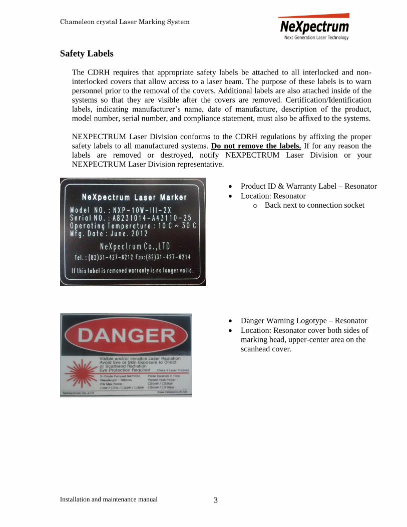
Product ID & Warranty Label – Resonator
Location: Resonator
o Back next to connection socket
Danger Warning Logotype – Resonator
Location: Resonator cover both sides of
marking head, upper-center area on the
scanhead cover.

Chameleon crystal Laser Marking System
Installation and maintenance manual 4
Aperture Label
Location: Scanhead
o On sides of F-theta lens socket.
Defeatably-Interlocked Protective Housing
Label
Location: Resonator cover
o Both sides under Dnager logotype
label.
Laser warning sign
Location: Scanhead
o Front center..

Chameleon crystal Laser Marking System
Installation and maintenance manual 5
Safety Warning Symbols and Definitions
- Caution, danger, or seriousness
- Caution – High voltage
- Eye protection with specified optical density required
- Customer repair, disassembly, or alteration forbidden
- Do not place hands in marking area when laser is on as it may
result in skin burns.

Chameleon crystal Laser Marking System
Installation and maintenance manual 6
Packaging Contents
The CHAMELEON laser marking system is shipped in one box; with the marking head and
the laser controller.
The box with the marking head
(1) Marking scan head 1
The box with the laser controller
(1) Laser Controller 1
(2) NeXmark software & Driver with manuals 1
(3) D-Sub 15pin connector 1
(4) D-sub 9pin connector 1
(5) D-sub-17W2 connector. 1
(6) Standard F-theta lens(100mm or 160mm) 1
(7) Green License Key (USB) 1
Note: An NEXPECTRUM Laser Division service technician will install the first system
shipped to each customer. Please do not try to unpack or set up the system; NEXPECTRUM
Laser Division will not guarantee optimal operation under such circumstances..

Chameleon crystal Laser Marking System
Installation and maintenance manual 7
System Overview
Features Diode Pumped Solid State Laser (DPSSL)
The CHAMELEON uses a Laser Diode to pump a resonator cavity, which emits laser
light at a wavelength of 1064 nm (near IR). The light is then focused and steered by the
marking system to mark on various types materials. The marking occurs by thermal
excitation, absorption of the light, by the substrate either by ablating the surface or an
induced chemical reaction leading to a sharp contrast between the marked area and the
material being marked.
The Laser Diode output is single chip solid-state Laser, which is mounted inside of the
resonator. The DPSS Laser provides a consistent power level over extended periods of
time. Unlike conventional flash lamp laser systems, it greatly reduces maintenance costs
and time.
The CHAMELEON features a factory-sealed Laser cavity design, which eliminates the
possibility of internal optics contamination in a dusty or humid environment, and
drastically prolongs the life of the system.
Microprocessor Controlled
The Proprietary CPU inside the controller controls the operation of the DPSS Laser.
The CHAMELEON offers expanded automation operation capabilities via simple
software interface and / or digital I/O port to ease its integration into an industrial or
OEM environment.
Air Cooled
Thermoelectric cooling eliminates the need for external cooling. A highly efficient heat
management system provides stable power output over a wide range of ambient
temperatures.

Chameleon crystal Laser Marking System
Installation and maintenance manual 8
Installation and Connection
NEXPECTRUM Laser Division personnel will perform initial installation and connection.
Installation Place the stand for the marking head on a level surface.
Place the marking head of the CHAMELEON onto its stand.
Secure marking head to stand using M5-bolts and lock washers. Bolts should be finger
tight plus a 1/4 turn.
Connect the power cords from the AC inlet on the controller and marker to an appropriate
AC outlet. For areas other than South Korea, the customer is responsible for providing
the necessary power cords or adapters to meet the connection configuration on the AC
outlet. The use of a surge protector is recommended.
Operating Environment Before installing and operating the system, verify that the operating environment meets the
following guidelines.
Avoid places where the system may be exposed to high levels of vibration, humidity,
electrical noise, dust, oil mist or other contaminants.
The system is equipped with a thermoelectric cooling system. Although the system is
fully functional within the temperature range of 10C~35°C (50°F~95°F), it is
recommended that the ambient operating temperature range remain between 16°C~24°C
(61°F~75°F).
To operate safely, properly ventilate the controller and marking head. Both the marker
head and the controller require airflow to their panels. Insure that there is a minimum of
5cm (2”) open area around the marking head and the rear of the controller for proper air
circulation. This space should also be maintained for accessibility to any operating
controls on the rear panel of the controller and marker.

Chameleon crystal Laser Marking System
Installation and maintenance manual 9
Exhaust The CHAMELEON requires external exhaust if installed. A rigid duct should be used
between the vacuum unit and the marking system. The exhaust tubing should be smooth-
walled and have as few bends as possible. Use the duct with a diameter that matches the
exhaust unit. Do not connect the rigid duct directly to the marking system. The blower
vibrations can be isolated if a short piece of industrial-grade, wire-reinforced rubber tubing is
used at the end of the duct.
Connection
1) Set the marking head and Laser controller on the work station.
a) Verify that the distance between them are not over 2M
b) Connect the power cable to the controller.
Use with ventilator. Toxic fumes may be generated when marking some materials.
CAUTION
Divide and maintain a separate, interlocked working area.
CAUTION
Use eye protection goggles. Use eye protection goggles when using Class IV systems.
Wear eye protection with optical density of 5 or higher
at appropriate wavelength.
CAUTION

Chameleon crystal Laser Marking System
Installation and maintenance manual 10
c) Connect the power cable of the marking head to a grounded surge protected power
outlet.
d) Connect the Scanhead cable to controller. (D-sub 15pin connector black end)
e) Connect the Resonator cable to the controller with - screw. (17W2 connector silver
end)
f) Connect the other end of the Scanhead cable to marking head..
g) Connect the Resonator cable to the marking head.
External I/O connection

Chameleon crystal Laser Marking System
Installation and maintenance manual 11
h) Connect the Data cable from controller to marking head.
2) Set the PC on the table..
a) Connect the electric connection for the PC.
b) Connect the power cable to a grounded surge protected power outlet.
3) Insert the USB key on to the PC.
4) Connect the USB cable from the controller to PC.

Chameleon crystal Laser Marking System
Installation and maintenance manual 12

Chameleon crystal Laser Marking System
Installation and maintenance manual 13
Operation
The CHAMELEON is composed of the marking head, laser diode controller and a personal
computer (marking software: NeXMark).
Beam path alignment is factory set. An NEXPECTRUM Laser Division factory trained
laser technician should perform any further alignment of the beam path if it is necessary.
CAUTION – Use of controls or adjustments or performance of procedures other than
those specified herein may result in hazardous radiation exposure.
Hardware driver installation
Step 1 Make sure all the cables and power are properly
connected as page. 9. Turn on the PC
Step 2 Check the PC if license key(USB) and USB port from
controller is connected with computer.
Step 3 Open “Device Manager” from control panel or access by
right clicking my computer and entering “Property”
Step 4 Switch on the controller. (Red) Check and see if
unknown device appear.
Step 5 Right click unknown device and press update.
Step 6 Press manually select update file. And select LMC driver
Supplied by NeXpectrum Division.
Step 7 Select “continue with installation” when warning
message appears.
Step 8 For windows XP, Step 6, 7, have to be repeated one more
time.
Step 9 Run “Dongle.exe” for license key registration. Run
NeXmark software.
NOTE: Using Windows 7 environment, may not run properly as software interface were
developed in XP environment. This could be resolved by entering property of NeXmark2.exe
and change the compatibility to XP service pack 2.
Flow of Operation Step 1 Turn on power. Before turning on power, make sure that the cables are properly
connected and the cap of F-theta lens is removed.
Step 2 Setting the focal length of the beam
Step 3 Set the LD current by turning a nozzle from Controller.
Step 4 Create the marking image with NeXmark. (See NeXmark User’s
Manual for details)

Chameleon crystal Laser Marking System
Installation and maintenance manual 14
Step 5 Set marking parameters with NeXmark (See NeXmark User’s
Manual for details)
Step 6 Mark object (See NeXmark User’s
Manual for details)
Power ON/OFF The CHAMELEON is composed of a marking head, laser diode controller and a personal
computer, each with a power switch. Please turn the power ON and OFF, according to the
following procedure.
Power ON Step 1 Turn the computer ON..
Step 2 Insert USB Key into the PC and see red light turns on..
Step 3 Turn the controller ON. The switch is located on the front panel (red). Check
scanhead if two green light turns on.
Step 4 Run NeXmark.
Step 5 Check if there are any error message appear on software screen
Step 6 Press laser “ON” button to turn on the power to laser.
Step 7 Turn to nozzle and set the power range above 60.
Note: Please allow the system to warm-up. If the system is operated without warm-up, it
may cause accelerated deterioration to the marking quality and to the internal components of
the marking system.
Power OFF Step 1 Make sure turn the power nozzle all the way down before turning off the power.
Step 2 Close NeXmark, then close Windows, and turn the computer off.
Recovery from Unexpected Shutdown In the event of a power failure, turn OFF all power switches, and restart the system using
Power ON procedures.
Setting the Focal Length of the Beam In order to produce quality marking, the distance between the edge of the lens and the item to
be marked (work distance) should be optimal. The focal point for a 100mm F-theta lens can
be found approximately 100mm from the edge of the lens. The focal point for a 160mm F-
theta lens can be found approximately 160mm from the edge of the lens and so on.
Step 1 Prepare a sample piece. Place the sample on the marking platform. The height of
the sample should be the same as the actual piece to be marked.
Step 2 Turn ON the power of the marker. Power should be turned on according to the
procedure described in “Power ON/OFF” on page 10.
Step 3 Run NeXmark software.
Step 4 Create an circle object and put to center on NeXmark screen; Check continuous
marking and press mark.

Chameleon crystal Laser Marking System
Installation and maintenance manual 15
Step 5 Move the sample up and down to find the point where the laser beam is the
brightest and sound emitted is the loudest. The height is now set at the optimal
work distance.
Operating the Controller
Features
The main function of the Controller is to power the LD (Laser Diode) and transfer the
laser output to the Marking Head through the optic cable.
The Controller programming tracks the temperature of the LD and crystal installed in the
Marker Head. Thermoelectric cooling modules control the temperature of the LD and
crystal ensuring stable marking power.
Functions on the Front Panel
Main power: Supply main power to both controller and marking head by switching
“ON”
Laser On: Even after power is being supplied to controller, it will not supply power to
LD unless pressing this button.(Only used in NXP-4W-III)
Temperature: Shows current temperature of LD. This could be control by GAIN nozzle
on the right.
Gain: Control heating and cooling for LD and by increasing, more cooling. (Only used in
NXP-4W-III)

Chameleon crystal Laser Marking System
Installation and maintenance manual 16
Maintenance
Maintenance and Inspection When maintaining and inspecting the system, please pay attention to the following:
Please turn the system off. If the maintenance is done immediately after the using the
system, make sure the surrounding temperature around the working field is safe.
Do not do attempt operations not specified in this manual.
The frequency of replacing maintenance parts and the cycle of inspection depend on the
system requirements, the types of applications, and the frequency of usage.
Laser Diode Replacement
Please contact factory for replacement of Laser Diode in order to maximize performance of
the system.
Inspection
Please inspect the following items regularly to make sure that the system runs at its peak
performance level.
Items Inspection Equipment for
inspection
Ambient
humidity/temperature
Measure the surrounding
temperature and make sure that it
is in the range of specifications
temperature1
humidity2
Thermometer/
Hydrometer
State of installation No excessive vibration at the
Marker Head.
Cleaning3 There is no dust on and around
devices.
There is no dirt on the cover glass
of F-Theta lens.
Lens tissue for
maintenance.
Methyl alcohol or
Isopropyl alcohol.
NOTE 1: Required temperature is 10C~35C
NOTE 2: Maximum humidity is 70% non-condensing.
NOTE 3: If the laser is exposed to excess dust, optical parts may become damaged by dirt
burnt with the laser beam.

Chameleon crystal Laser Marking System
Installation and maintenance manual 17
Cleaning
General cleaning of Laser Marker System
Basic cleaning of the system should be conducted on a daily basis. Dirt, debris, and other
build up may cause inaccurate operation and malfunction of the system. The marking system
is composed of sensitive optical and mechanical parts that are crucial for marking
performance. Even minor damage to one or several of these parts may jeopardize the
performance of the entire system.
Note: The frequency of cleaning depends on the number of operations and the types of
materials being marked. Consequently, increased use of the system and materials with higher
levels of particles will require more cleaning. Inspect the system and its applications to
determine proper cleaning cycles. Keep your investment clean and well maintained.
The Process of Cleaning
1. Make sure to turn the system off and disconnect all power cables before cleaning.
2. Thoroughly remove loose debris and vacuum the inner part of the working field.
3. Use a soft cloth to clean the working field. Do not spray the solution directly into the
working field to prevent the electrical components from being exposed to the liquid.
Cleaning the F-Theta Lens
Inspection of the F-Theta lens should be conducted regularly. Before cleaning, make sure to
turn off and disconnect the AC input cable. Cleaning should be performed as follows:
1. Remove the lens cap.
2. Clean the F-Theta lens while installed in the marking head. Notice: Do not remove the
F-Theta lens from the marking head! 3. Clean with methyl alcohol or isopropyl alcohol and a lens cleaning tissue.
Note:
Use tweezers and lens tissue for hard-to-reach spots.
Make sure to wipe in one direction to avoid adhesion of dust and scratching of the lens
surface. Do not wipe in both directions.
Keep the lens protected by securing the lens cover over the lens when the system is not in
use. Notice: Be sure to remove the lens cover prior to operation
Cleaning the Marker Head
Before cleaning, make sure to turn the power off and disconnect the AC input cable.
Clean the cover of the marker head with lint-free cloths and a mild detergent. Do not use
liquid detergent that is highly concentrated. To avoid electrical problems, keep the liquid
away from laser maker system.
Chameleon crystal Laser Marking System
Installation and maintenance manual 18
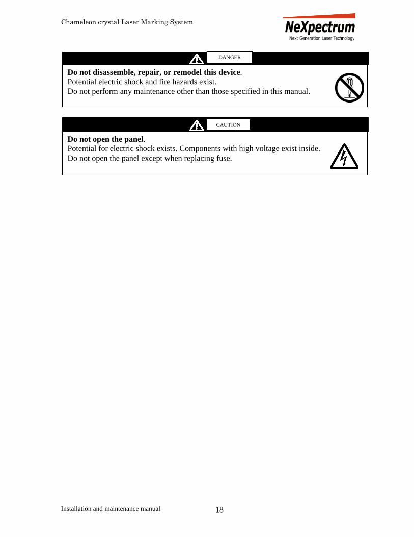
Do not open the panel.
Potential for electric shock exists. Components with high voltage exist inside.
Do not open the panel except when replacing fuse.
Do not disassemble, repair, or remodel this device.
Potential electric shock and fire hazards exist.
Do not perform any maintenance other than those specified in this manual.
CAUTION
DANGER

Chameleon crystal Laser Marking System
Installation and maintenance manual 19
Specifications and Dimensions
Specification (TYP value)
Items Specifications
Model CHAMELEON Series
Marker Head Laser source Semiconductor pumping Nd:YVO4
Beam wavelength 1,064 nm
Laser Output 8W (CW: Continuous Wave)
Peak Power* 60kW @ 10kHz
Q-switch pulse width* 6nsec @ 10kHz
Beam spot diameter 25 ~ 40 μm
Max marking area. 70mm x 70 mm,
110x110, 185x185
F-Theta Lens (Focal Length) 100mm, 160mm,
254mm,
Cooling system. Electronic cooling, Air cooling
Operational temperature range 10~35o Celsius
Operational humidity range* 70% non condensing
Consumption power Max 400W
Weight Approx. 13kg
Dimensions Refer to the dimension
drawing
Controller Model NXP-III-C
Setting Front panel key pad
Operational temperature range 10~35o Celsius
Operational humidity range* 70% non condensing
Power source AC 220, 10A, 50/60Hz
Consumption power Max 600W
Weight Approx. 12kg
Dimensions 3U
*Units stated at maximum output parameters
Environmental / Operating Conditions
The unit is for indoor use only.
The unit is for use at a maximum altitude of 3000 meters.
The unit is for use within the ambient temperature range of 100
C and 350
C.
The unit is for use at a maximum relative humidity of 70% for temperatures up to 240 C,
decreasing linearly to 50% relative humidity at 350
C.

Chameleon crystal Laser Marking System
Installation and maintenance manual 20
The Mains supply voltage fluctuation shall not exceed +/- 10%.
The unit is intended for INSTALLATION CATEGORY II.
The unit is intended for use in a POLLUTION DEGREE 2 ENVIRONMENT.

Chameleon crystal Laser Marking System
Installation and maintenance manual 21
Dimensions
Marking Head: Type CHAMELEON
Units – millimeters

Chameleon crystal Laser Marking System
Installation and maintenance manual 22
External I/O connection

Chameleon crystal Laser Marking System
Installation and maintenance manual 23

Chameleon crystal Laser Marking System
Installation and maintenance manual 24
Troubleshooting
SYMPTOM POSSIBLE CAUSES SOLUTION
Unit does not appear to
have power
Unit not plugged in, improper
connections, unit not turned on
Ensure that all power cords are properly
attached and plugged into a functional
electrical outlet.
Ensure that the key switch on the front of
the controller is in the ‘on’ position.
Ensure that the on/off switches on the
front of the controller and rear of the
marker are in the ‘on’ position.
Unit appears to have
power but does not
respond to laptop
commands
Improper connections, F-Theta
lens cap in place, laser not
turned on
Ensure all cables are properly attached
between computer, controller and marker
(see Cable Connection Chart on page 14).
Ensure that the F-Theta lens cap has been
removed from the bottom of the marker.
Ensure the ‘Run-Stop’ button has been
depressed on the front of the controller
and the ‘Laser On’ light is illuminated.
Unit does not engrave Improper focal distance,
improper work piece
positioning, loose cable
connection.
Ensure that the surface of the work piece
to be engraved is positioned in the focal
plane of the laser and that the work piece
itself is located in the engraving field (see
section on adjusting focal plane and using
the positioning diode option in
NeXmark). Check cable connection
Unit engraves with poor
quality
Improper work piece
positioning, improper marking
parameters, improper work
piece material
Ensure that the surface of the work piece
to be engraved is positioned in the focal
plane of the laser and is parallel to the
bottom of the marker (ie. flat).
Experiment with the controller current
and various marking parameters in
NeXmark to obtain the highest quality
mark. Ensure that the laser is able to
engrave on the work piece material (try
engraving the desired mark on a different
material).
Unit will not engrave or
engraves with poor quality
Defective, damaged or
misaligned unit
Software setting is incorrect.
If none of the previously outlined
solutions corrects the experienced
problem(s) then please contact
NEXPECTRUM-Laser customer service
personnel.

Chameleon crystal Laser Marking System
Installation and maintenance manual 25
Warranty
NEXPECTRUM Laser Division warrants all products manufactured by NEXPECTRUM Laser
Division to be free from defect in material and workmanship for a period of one (1) year from
the date of purchase and (2) year for laser diode part. Such warranty includes all parts and labor.
NEXPECTRUM Laser Division will pass through to the purchaser any warranties issued by the
original manufacturer. If the original manufacturer agrees to replace or repair the defective
part(s), NEXPECTRUM Laser Division will refit such part(s) at applicable charge. Only after
approval and assignment of a Return Material Authorization (RMA), products repaired under
this warranty are to be returned to NEXPECTRUM Laser Division, in the original packaging,
shipping charges prepaid, by the user who assumes all risk and cost of shipping to and from
NEXPECTRUM Laser Division’s facility.
For defective products, other than those covered by above, examination shall be made to disclose
any defect to NEXPECTRUM Laser Division’s satisfaction and proof that the product was
defective at the time of shipment. NEXPECTRUM Laser Division must receive immediate
written notice upon discovery of such alleged defect and the alleged defective products must be
returned to NEXPECTRUM Laser Division no later than 30 days after NEXPECTRUM Laser
Division has issued an RMA Number. NEXPECTRUM Laser Division will repair or replace the
product at its discretion. This warranty shall not apply to any products that have been used other
than for their intended purpose, or to any of the products whose composition have been changed
in any way, to parts requiring standard maintenance, or to any of the products which have been
subjected to, but not limited to, adverse storage conditions, misuse, negligence, or accident.
NEXPECTRUM Laser Division shall not be held liable for damages or delays caused by
defective raw materials and manufacture, nor shall NEXPECTRUM Laser Division be liable for
consequential damages in cases of failure to meet the conditions of warranty. The full liability of
NEXPECTRUM Laser Division under this clause is the repair or replacement of defective parts,
solely at its discretion.
The customer is responsible for the proper installation and operation of the equipment. A factory
representative will be available at start-up for a nominal fee. Contact your NEXPECTRUM
Laser Division representative for further information.
THIS EXPRESS WARRANTY IS GIVEN IN LIEU OF ALL OTHER WARRANTIES. ALL
OTHER WARRANTIES, AND ESPECIALLY, THE IMPLIED WARRANTIES OF
MERCHANTABILITY AND FITNESS FOR PARTICULAR PURPOSES, ARE EXCLUDED.
No person, agent, or representative of NEXPECTRUM Laser Division is authorized to give any
other warranties on NEXPECTRUM Laser Division's behalf, or to assume any other liability in
connection with any of the products.

Chameleon crystal Laser Marking System
Installation and maintenance manual 26
NOTE: Proper use and/or storage of the system must conform to the following criteria or the
warranty is voided:
Avoid places where the system may be exposed to high levels of vibration, humidity,
electrical noise, dust, or oil mist.
Keep in an area with an ambient operating range between 10°C~35°C.
For safety purposes, proper ventilation of the controller and the marking head is required.
Both the marker head and the controller require airflow to their rear panels. Insure that there
is a minimum of 5cm (2”) open area around the marking head and the rear of the controller
for proper air circulation. This space should also be maintained for accessibility to any
operating controls on the rear panel of the controller and marker.
WARNING - Any modification, alteration, opening or other changes to NEXPECTRUM Laser
Division's products will void any warranties and could cause damage or injury to the user of the
products. NEXPECTRUM Laser Division will not be held liable for consequential damages
arising from any misuse of their products. In line with our policy of continuous product
development, NEXPECTRUM Laser Division reserves the right to amend specifications and/or
prices without prior notice.
This warranty shall constitute the exclusive remedy available to the user and shall be considered
a condition of sale and use.
Purchasing company:
Purchasing representative’s name: Title:
Signature: Date:
NEXPECTRUM Laser Division representative’s Name: Title:
Signature: Date: