
Challenges to Demonstration “Review of Technology ... the boiler.pdf · Alstom SchwarzePumpe 2008...
53
Challenges to Demonstration “Review of Technology Development Beyond the Oxyfuel Combustion Boiler” Stanley Santos IEA Greenhouse Gas R&D Programme 39 th IFRF TOTEM & RELSCOM Workshop Pisa, Italy 18 June 2013
Transcript of Challenges to Demonstration “Review of Technology ... the boiler.pdf · Alstom SchwarzePumpe 2008...
Challenges to Demonstration
“Review of Technology Development Beyond
the Oxyfuel Combustion Boiler”
Stanley Santos
IEA Greenhouse Gas R&D Programme
39th IFRF TOTEM & RELSCOM Workshop
Pisa, Italy
18 June 2013

IEA Greenhouse Gas R&D Programme
• A collaborative research programme founded in 1991
• Aim: Provide members with definitive information on the role that technology can play in reducing greenhouse gas emissions.
• Producing information that is:
� Objective, trustworthy, independent
� Policy relevant but NOT policy prescriptive
2
� Reviewed by external Expert Reviewers
� Subject to review of policy implications by Members
• IEA GHG is an IEA Implementing Agreement in which the Participants contribute to a common fund to finance the activities.
• Activities: Studies and Reports (>120); International Research Networks : Wells, Risk, Monitoring, Modelling, Oxyfuel, Capture, Social Research, Solid Looping; Communications (GHGT conferences, IJGGC, etc); facilitating and focusing R&D and demonstration activities e.g. Weyburn

Members and Sponsors
3
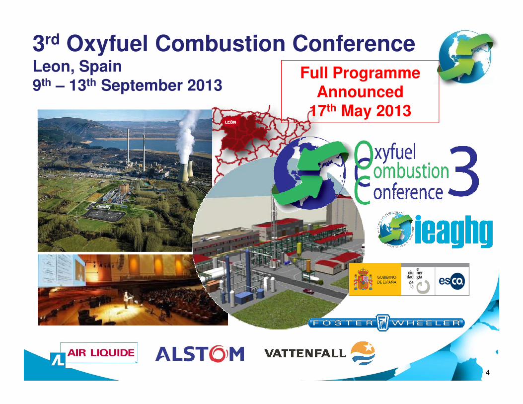
3rd Oxyfuel Combustion ConferenceLeon, Spain9th – 13th September 2013
Full Programme Announced
17th May 2013
4
5
UPDATE TO THE CURRENT
DEVELOPMENT OF OXYFUEL
COMBUSTION
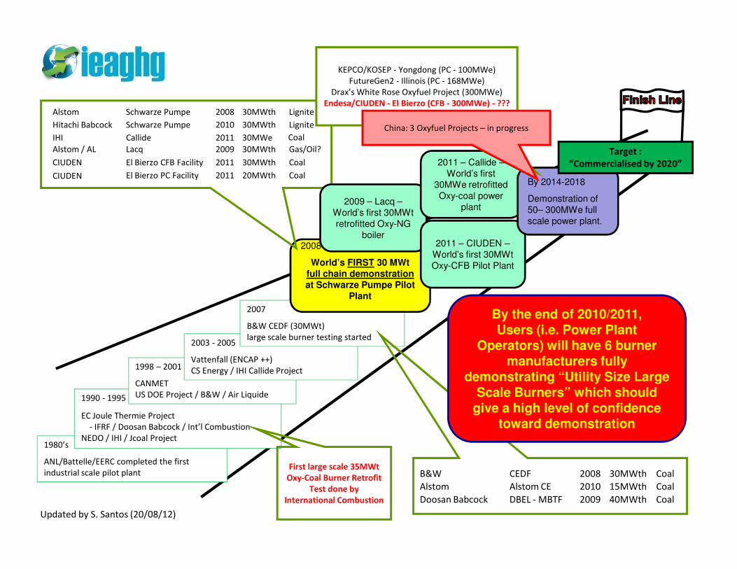
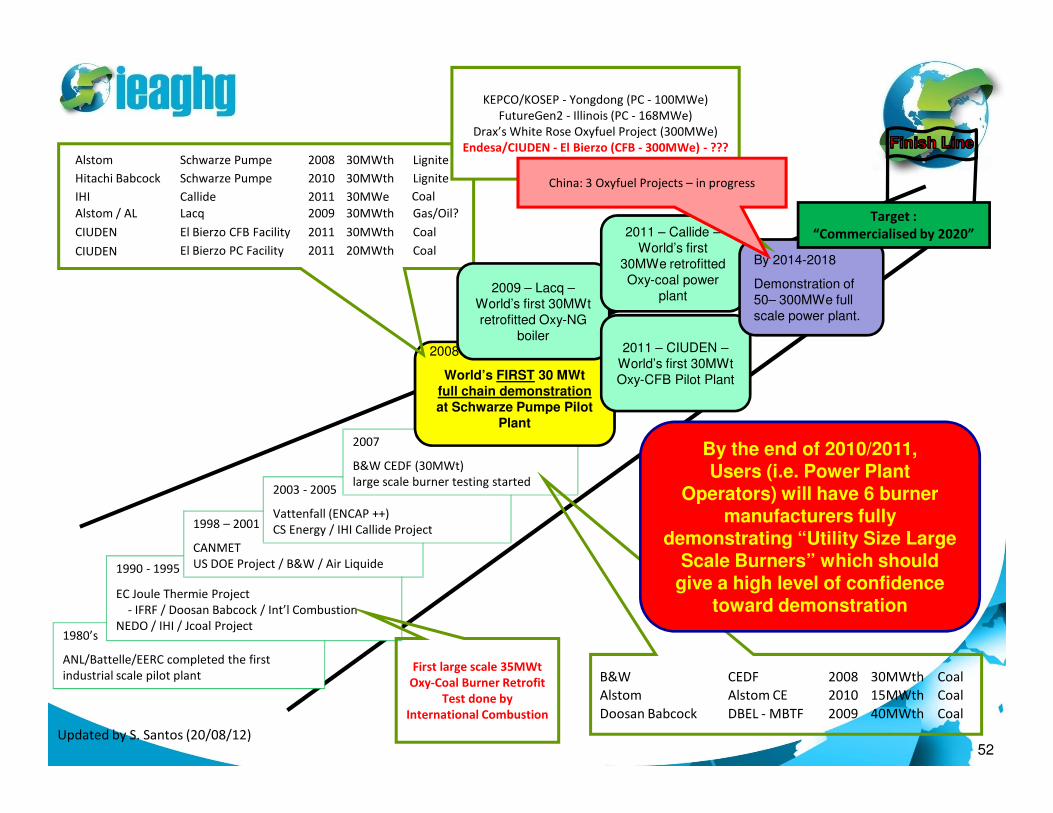
Alstom Schwarze Pumpe 2008 30MWth Lignite
Hitachi Babcock Schwarze Pumpe 2010 30MWth Lignite
IHI Callide 2011 30MWe
Alstom / AL Lacq 2009 30MWth Gas/Oil?
CIUDEN El Bierzo CFB Facility 2011 30MWth Coal
El Bierzo PC Facility 2011 20MWth Coal
Coal
CIUDEN
2008
World’s FIRST 30 MWt
full chain demonstration
at Schwarze Pumpe Pilot
2009 – Lacq –
World’s first 30MWt
retrofitted Oxy-NG
boiler2011 – CIUDEN –
World’s first 30MWt
Oxy-CFB Pilot Plant
2011 – Callide –
World’s first
30MWe retrofitted
Oxy-coal power
plant
By 2014-2018
Demonstration of
50– 300MWe full
scale power plant.
Target :
“Commercialised by 2020”
KEPCO/KOSEP - Yongdong (PC - 100MWe)
FutureGen2 - Illinois (PC - 168MWe)
Drax’s White Rose Oxyfuel Project (300MWe)
Endesa/CIUDEN - El Bierzo (CFB - 300MWe) - ???
China: 3 Oxyfuel Projects – in progress
1980’s
ANL/Battelle/EERC completed the first
industrial scale pilot plant
1990 - 1995
EC Joule Thermie Project
- IFRF / Doosan Babcock / Int’l Combustion
NEDO / IHI / Jcoal Project
First large scale 35MWt
Oxy-Coal Burner Retrofit
Test done by
International Combustion
1998 – 2001
CANMET
US DOE Project / B&W / Air Liquide
2003 - 2005
Vattenfall (ENCAP ++)
CS Energy / IHI Callide Project
B&W CEDF 2008 30MWth Coal
Alstom Alstom CE 2010 15MWth Coal
Doosan Babcock DBEL - MBTF 2009 40MWth Coal
2007
B&W CEDF (30MWt)
large scale burner testing started
Updated by S. Santos (20/08/12)
at Schwarze Pumpe Pilot
Plant
By the end of 2010/2011, Users (i.e. Power Plant
Operators) will have 6 burner manufacturers fully
demonstrating “Utility Size Large Scale Burners” which should
give a high level of confidence toward demonstration
Concluding Remarks –Update to Key Demonstration Projects
• Based on the Conclusions from 2nd Oxyfuel Combustion Conference – This Technology is READY for DEMONSTRATION
• Lost of Janschwalde Project is a setback…
• Success in the commissioning of Callide Project is an important milestone.
7
• Three important projects on-going…
• FutureGen2 (USA)
• White Rose Project (UK)
• Yong Dong Project (South Korea)
• Other new projects – currently under development
• Huazhong Project (China)
• 2 Other Oxyfuel Demonstration Projects under considersation in China

Presentation Outline…
Oxygen
Production
8
CO2 Processing Unit
Oxygen Production
• Facts:
• Today, only the Cryogenic Air Separation Unit or
ASU is capable of delivering the oxygen demand
of a large oxyfuel combustion boiler for power
plant with CO capture…
9
plant with CO2 capture…
• For every 500MWe net output you will require
~10,000 t/d O2
o Low Purity (95-97%)*
o Low Pressure (nearly atmospheric)
At 95% purity will have 2% N2 and 3% Ar
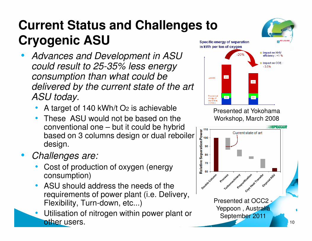
Current Status and Challenges to Cryogenic ASU• Advances and Development in ASU
could result to 25-35% less energy consumption than what could be delivered by the current state of the art ASU today.• A target of 140 kWh/t O2 is achievable
• These ASU would not be based on the Presented at Yokohama
Workshop, March 2008
10
• These ASU would not be based on the conventional one – but it could be hybrid based on 3 columns design or dual reboiler design.
• Challenges are:• Cost of production of oxygen (energy
consumption)
• ASU should address the needs of the requirements of power plant (i.e. Delivery, Flexibility, Turn-down, etc...)
• Utilisation of nitrogen within power plant or other users.
Workshop, March 2008
Presented at OCC2 -
Yeppoon , Australia
September 2011
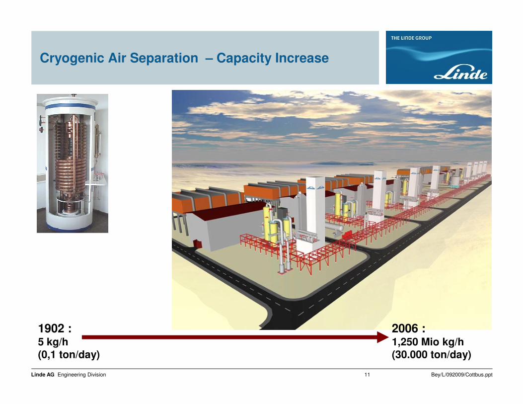
Cryogenic Air Separation – Capacity Increase
Bey/L/092009/Cottbus.pptLinde AG Engineering Division 11
1902 :5 kg/h
(0,1 ton/day)
2006 :1,250 Mio kg/h
(30.000 ton/day)
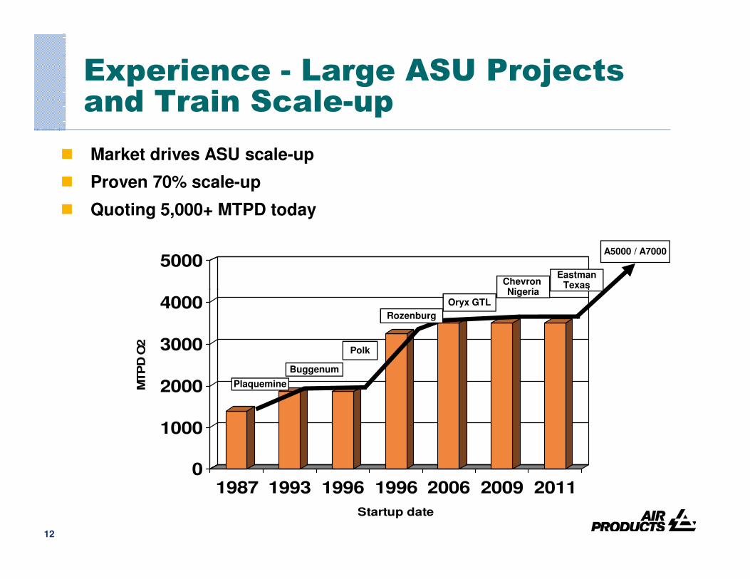
Experience - Large ASU Projects and Train Scale-up
5000
� Market drives ASU scale-up
� Proven 70% scale-up
� Quoting 5,000+ MTPD today
Chevron Nigeria
EastmanTexas
A5000 / A7000
12
0
1000
2000
3000
4000
MTP
D O
2
1987 1993 1996 1996 2006 2009 2011
Startup date
Buggenum
Oryx GTL
Polk
Plaquemine
NigeriaTexas
Rozenburg

13
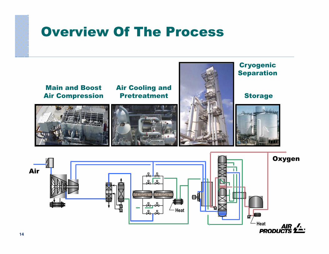
Overview Of The Process
Main and Boost
Air Compression
Air Cooling and
Pretreatment Storage
Cryogenic
Separation
14
Heat
Air
Heat
Oxygen
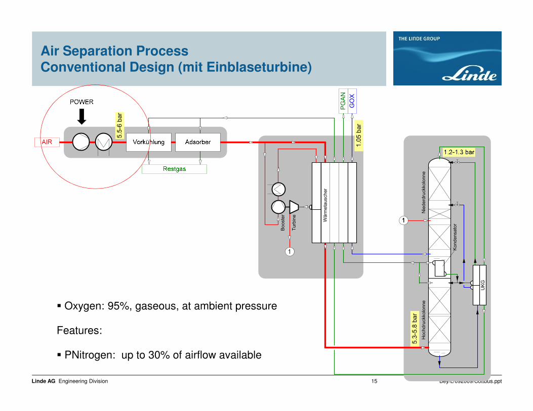
Air Separation Process Conventional Design (mit Einblaseturbine)
tauscher
PGAN
GOX
derdruckkolonne
5.5-6 bar
1.05 bar
Bey/L/092009/Cottbus.pptLinde AG Engineering Division 15
Wärmet
Booster
Turbine
Kondensator
Nied
Hochdruckkolonne
UKG
5.3-5.8 bar
� Oxygen: 95%, gaseous, at ambient pressure
Features:
� PNitrogen: up to 30% of airflow available
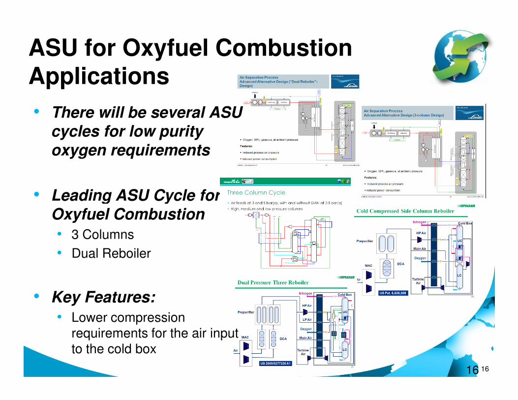
ASU for Oxyfuel Combustion Applications
• There will be several ASU cycles for low purity oxygen requirements
• Leading ASU Cycle for
16
• Leading ASU Cycle for Oxyfuel Combustion
• 3 Columns
• Dual Reboiler
• Key Features:
• Lower compression requirements for the air input to the cold box
16

McCabe Thiele Diagrams
Double ColumnSingle Pressure SideColumn Reboiler
Equilibrium
line
Operating
lines
17
Cold Compressed Side Column Reboiler
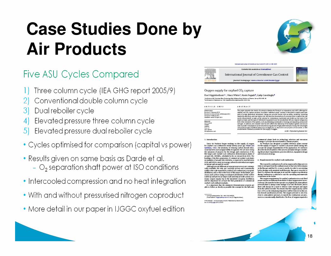
Case Studies Done by
Air Products
18
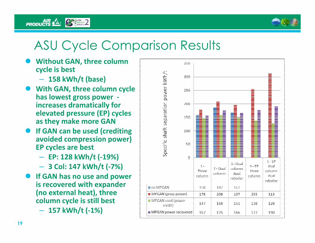
ASU Cycle Comparison Results� Without GAN, three column
cycle is best
– 158 kWh/t (base)
� With GAN, three column cycle has lowest gross power -increases dramatically for elevated pressure (EP) cycles as they make more GAN
19
as they make more GAN
� If GAN can be used (crediting avoided compression power) EP cycles are best
– EP: 128 kWh/t (-19%)
– 3 Col: 147 kWh/t (-7%)
� If GAN has no use and power is recovered with expander (no external heat), three column cycle is still best
– 157 kWh/t (-1%)
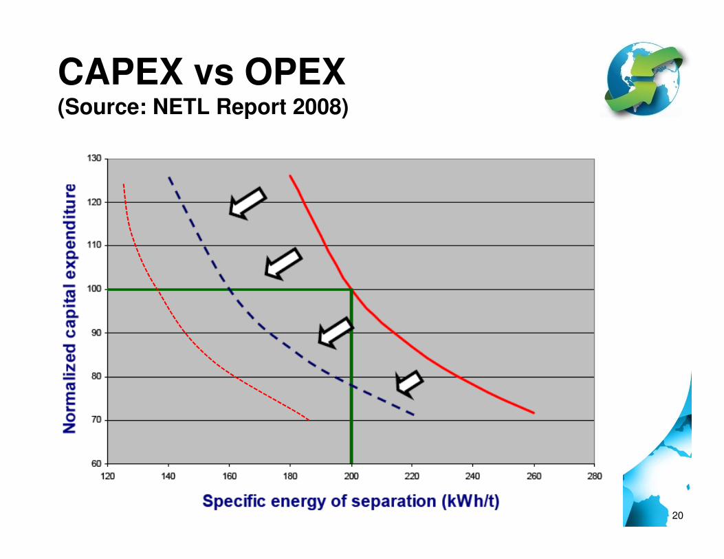
CAPEX vs OPEX(Source: NETL Report 2008)
20

ASU Interface to the Boiler
21
An important aspects to this interface is the stability of the flame and you need to understand that flame stability envelope
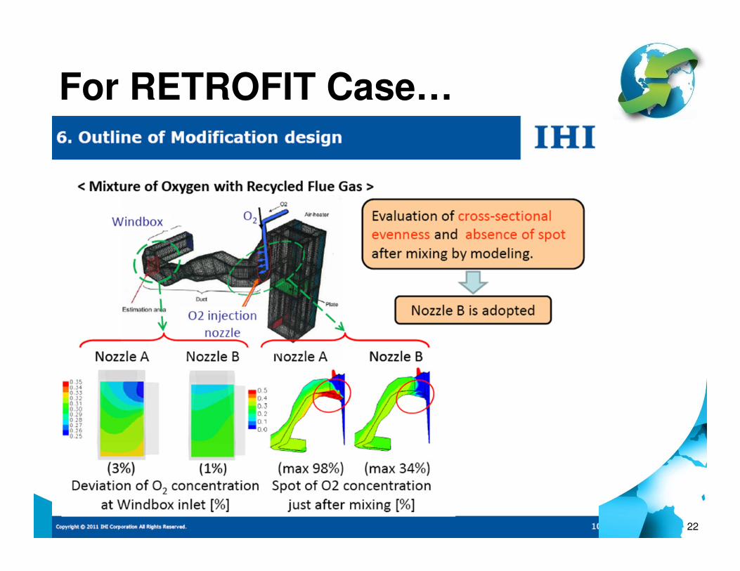
For RETROFIT Case…
22
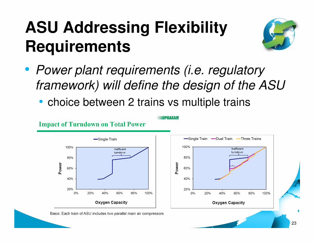
ASU Addressing Flexibility
Requirements
• Power plant requirements (i.e. regulatory framework) will define the design of the ASU
• choice between 2 trains vs multiple trains
23

ASU Addressing Flexibility
Requirements
• Other options include the installation of liquid gas storage system could provide additional flexibility and opportunities…
24
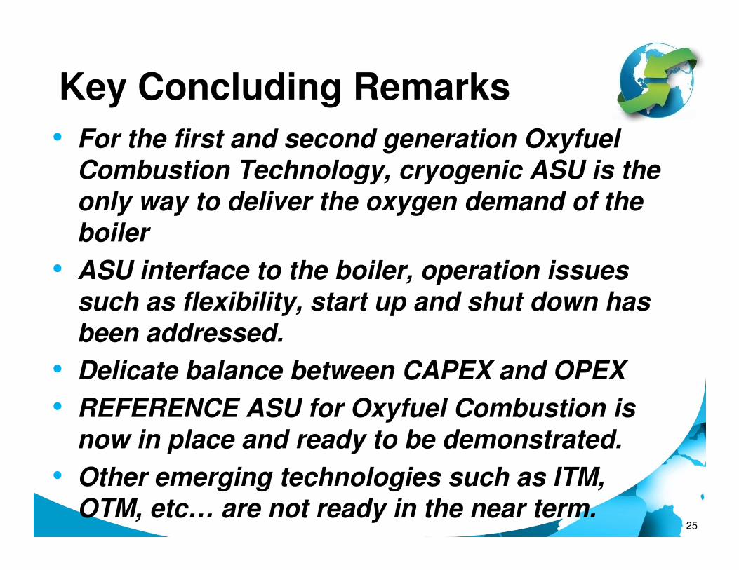
Key Concluding Remarks
• For the first and second generation Oxyfuel Combustion Technology, cryogenic ASU is the only way to deliver the oxygen demand of the boiler
• ASU interface to the boiler, operation issues
25
•such as flexibility, start up and shut down has been addressed.
• Delicate balance between CAPEX and OPEX
• REFERENCE ASU for Oxyfuel Combustion is now in place and ready to be demonstrated.
• Other emerging technologies such as ITM, OTM, etc… are not ready in the near term.
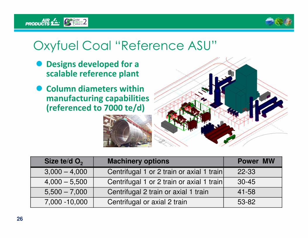
Oxyfuel Coal “Reference ASU”
� Designs developed for a scalable reference plant
� Column diameters within manufacturing capabilities (referenced to 7000 te/d)
26
Size te/d O2 Machinery options Power MW
3,000 – 4,000 Centrifugal 1 or 2 train or axial 1 train 22-33
4,000 – 5,500 Centrifugal 1 or 2 train or axial 1 train 30-45
5,500 – 7,000 Centrifugal 2 train or axial 1 train 41-58
7,000 -10,000 Centrifugal or axial 2 train 53-82

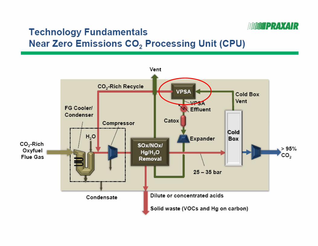
CO2 Processing Unit
• Key Areas of Development in CO2 Processing Unit or CPU
o Compression and Removal of minor impurities (NOx, SOx and Other Trace elements
o Dehydration Unit
o Cryogenic Separation of Inerts (Cold Box development)
27
o Cryogenic Separation of Inerts (Cold Box development)
o Additional capture of CO2 from the CPU
• Other key driver to the development is the specification of the CO2.
o Management of CO2 purity requires good interaction between boiler, flue gas processing and CPU
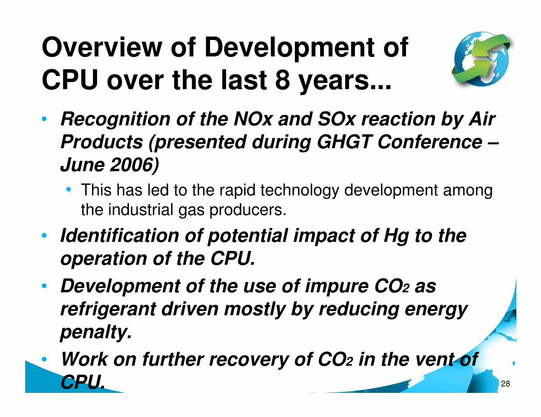
Overview of Development of
CPU over the last 8 years...
• Recognition of the NOx and SOx reaction by Air Products (presented during GHGT Conference –June 2006)
• This has led to the rapid technology development among
the industrial gas producers.
28
the industrial gas producers.
• Identification of potential impact of Hg to the operation of the CPU.
• Development of the use of impure CO2 as refrigerant driven mostly by reducing energy penalty.
• Work on further recovery of CO2 in the vent of CPU.
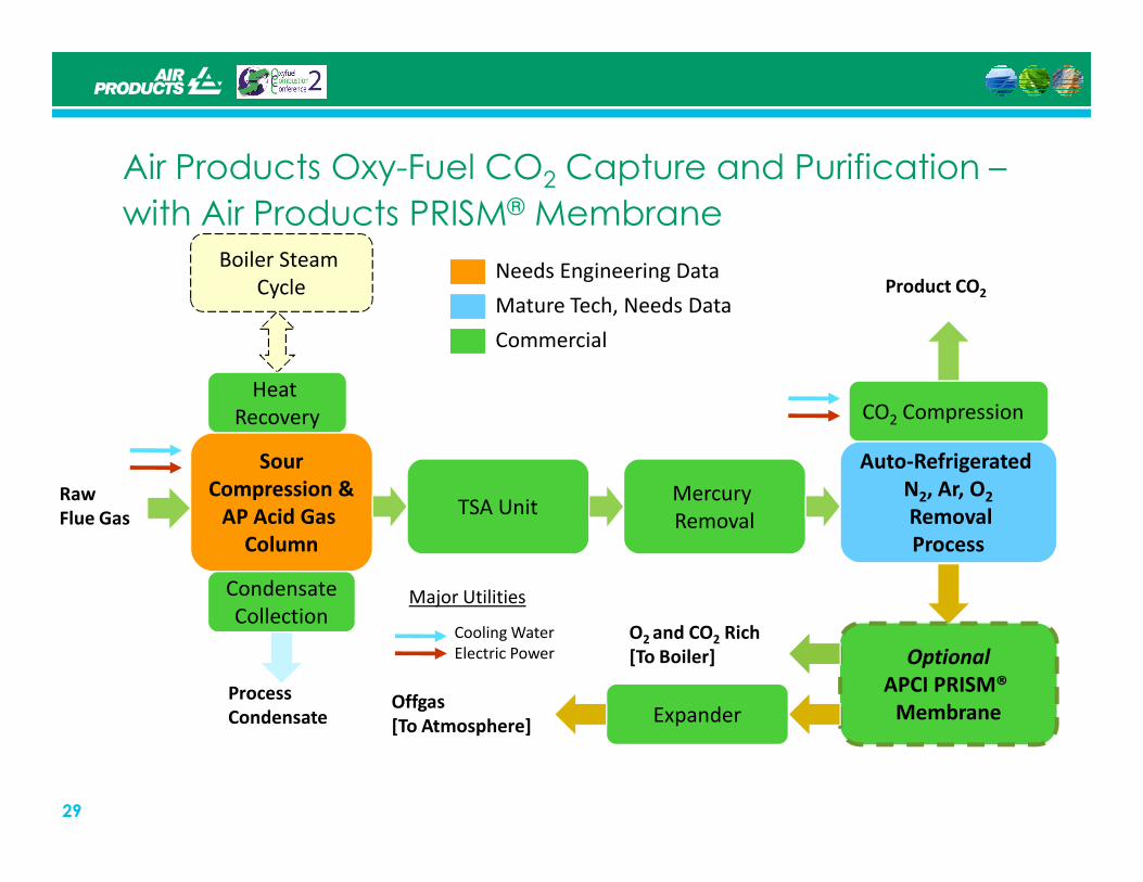
Air Products Oxy-Fuel CO2 Capture and Purification –
with Air Products PRISM® Membrane
Product CO2
Heat
Recovery CO2 Compression
Boiler Steam
Cycle
Commercial
Mature Tech, Needs Data
Needs Engineering Data
29
Raw
Flue Gas
Offgas
[To Atmosphere]
Process
Condensate
Sour
Compression &
AP Acid Gas
Column
Condensate
Collection
TSA UnitMercury
Removal
Auto-Refrigerated
N2, Ar, O2
Removal
Process
Optional
APCI PRISM®
Membrane
O2 and CO2 Rich
[To Boiler]
Major Utilities
Cooling Water
Electric Power
Expander

Activated
carbon filter
Recti-
fication
Compressor
building
Analysis
CO2-tanks
(2x180 m³)
Trailer
docking
station
Analysis
container
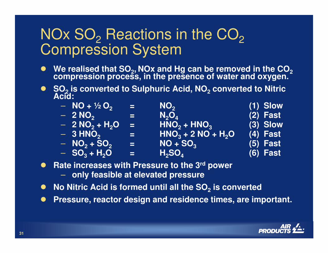
NOx SO2 Reactions in the CO2Compression System� We realised that SO2, NOx and Hg can be removed in the CO2
compression process, in the presence of water and oxygen.
� SO2 is converted to Sulphuric Acid, NO2 converted to Nitric Acid:
– NO + ½ O2 = NO2 (1) Slow– 2 NO2 = N2O4 (2) Fast– 2 NO2 + H2O = HNO2 + HNO3 (3) Slow
31
– 2 NO2 + H2O = HNO2 + HNO3 (3) Slow– 3 HNO2 = HNO3 + 2 NO + H2O (4) Fast– NO2 + SO2 = NO + SO3 (5) Fast– SO3 + H2O = H2SO4 (6) Fast
� Rate increases with Pressure to the 3rd power– only feasible at elevated pressure
� No Nitric Acid is formed until all the SO2 is converted
� Pressure, reactor design and residence times, are important.
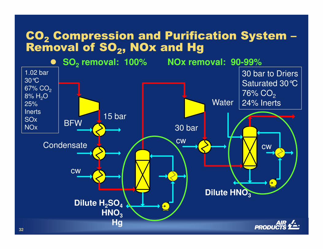
CO2 Compression and Purification System –Removal of SO2, NOx and Hg
1.02 bar
30°C
67% CO2
8% H2O
25%
Inerts
SOx
NOx
30 bar to DriersSaturated 30°C76% CO2
24% Inerts
� SO2 removal: 100% NOx removal: 90-99%
BFW15 bar
30 bar
Water
32
NOx
Dilute H2SO4
HNO3
Hg
BFW
Condensate
cw
30 bar
cwcw
Dilute HNO3
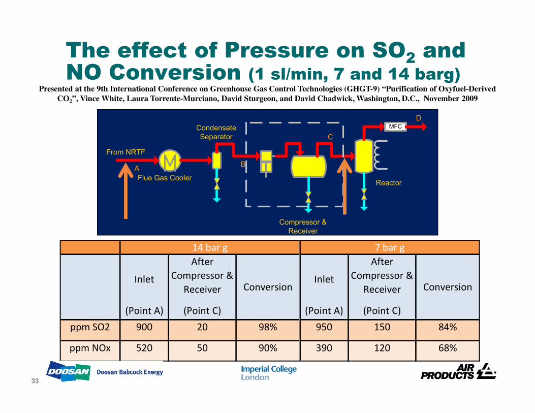
AB
C
MFC
D
From NRTF
Flue Gas Cooler
Condensate
Separator
Reactor
The effect of Pressure on SO2 and NO Conversion (1 sl/min, 7 and 14 barg)
Presented at the 9th International Conference on Greenhouse Gas Control Technologies (GHGT-9) “Purification of Oxyfuel-Derived
CO2”, Vince White, Laura Torrente-Murciano, David Sturgeon, and David Chadwick, Washington, D.C., November 2009
33
Compressor &
Receiver
Inlet
After
Compressor &
ReceiverInlet
After
Compressor &
Receiver
(Point A) (Point C) (Point A) (Point C)
ppm SO2 900 20 98% 950 150 84%
ppm NOx 520 50 90% 390 120 68%
ConversionConversion
7 bar g14 bar g
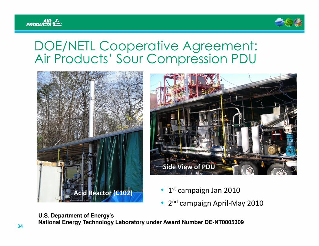
DOE/NETL Cooperative Agreement: Air Products’ Sour Compression PDU
34
Acid Reactor (C102)
Side View of PDU
• 1st campaign Jan 2010
• 2nd campaign April-May 2010
U.S. Department of Energy's National Energy Technology Laboratory under Award Number DE-NT0005309
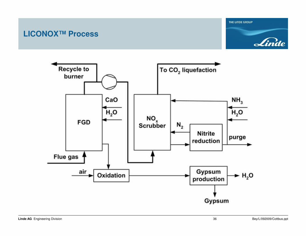
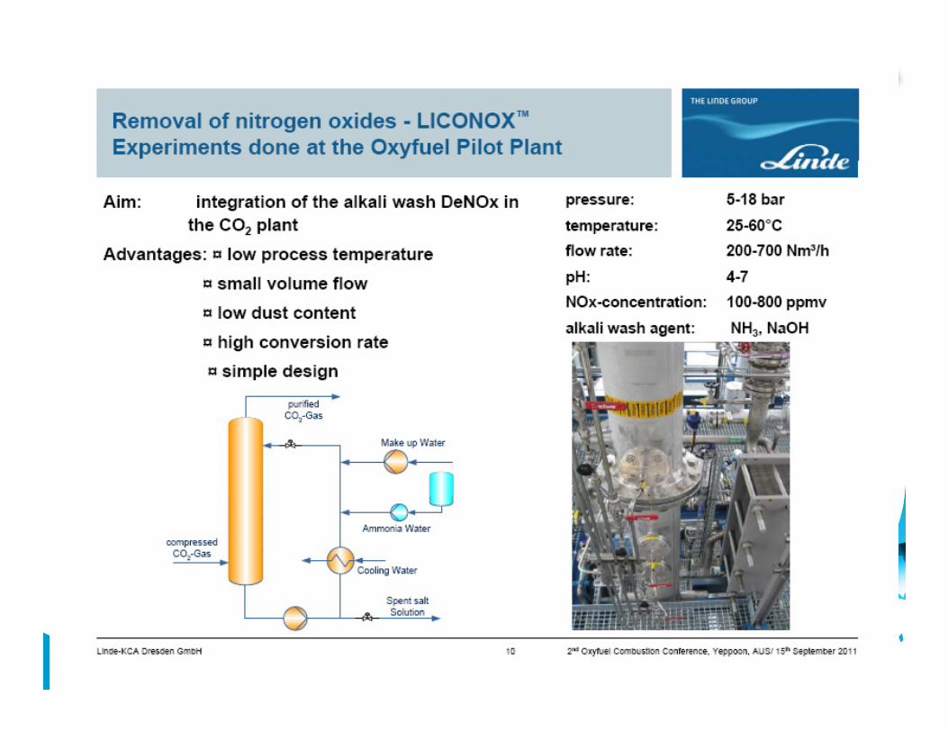
LICONOX™ Process
Bey/L/092009/Cottbus.pptLinde AG Engineering Division 36
37

38

39

Sulphuric Acid Method Activated Carbon Method
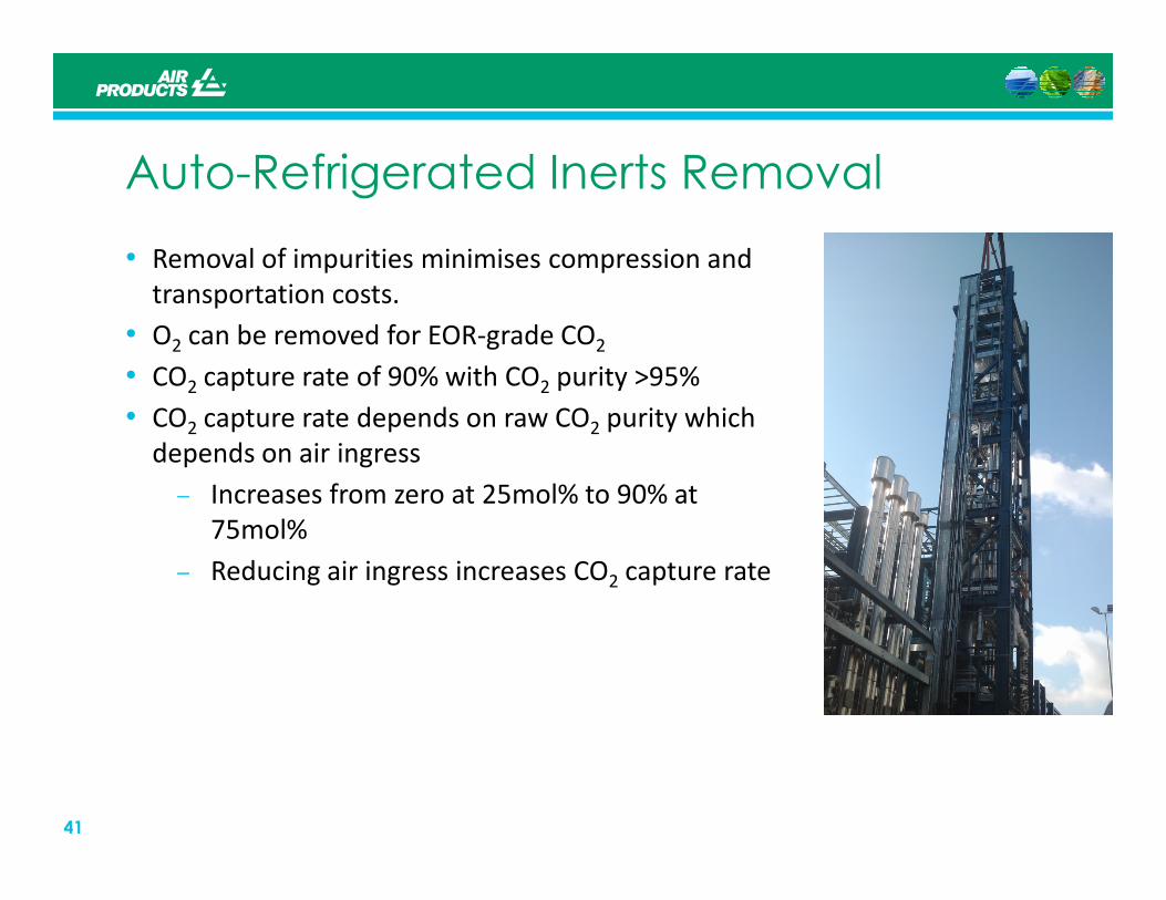
Auto-Refrigerated Inerts Removal
• Removal of impurities minimises compression and
transportation costs.
• O2 can be removed for EOR-grade CO2
• CO2 capture rate of 90% with CO2 purity >95%
• CO2 capture rate depends on raw CO2 purity which
depends on air ingress
41
depends on air ingress
– Increases from zero at 25mol% to 90% at
75mol%
– Reducing air ingress increases CO2 capture rate
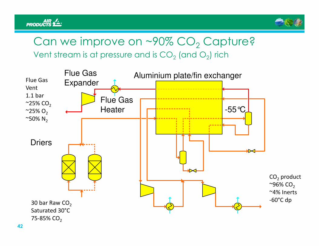
Can we improve on ~90% CO2 Capture?Vent stream is at pressure and is CO2 (and O2) rich
Flue Gas
Vent
1.1 bar
~25% CO2
~25% O2
~50% N2
Flue Gas Expander
Aluminium plate/fin exchanger
Flue GasHeater -55°C
42
Driers
30 bar Raw CO2
Saturated 30°C
75-85% CO2
CO2 product
~96% CO2
~4% Inerts
-60°C dp
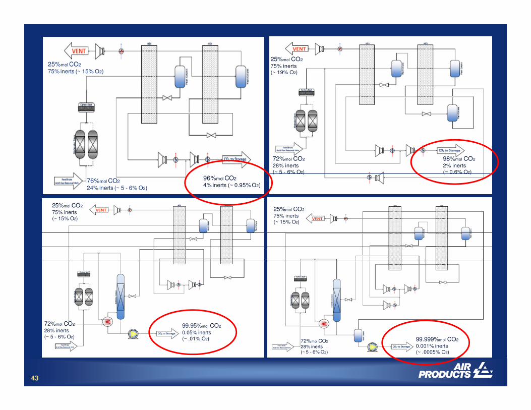
76%mol CO2
24% inerts (~ 5 - 6% O2)
96%mol CO2
4% inerts (~ 0.95% O2)
25%mol CO2
75% inerts (~ 15% O2)
72%mol CO2
28% inerts
(~ 5 - 6% O2)
98%mol CO2
2% inerts
(~ 0.6% O2)
25%mol CO2
75% inerts
(~ 19% O2)
25%mol CO2
43
72%mol CO2
28% inerts(~ 5 - 6% O2)
99.999%mol CO2
0.001% inerts(~ .0005% O2)
25%mol CO2
75% inerts (~ 15% O2)
72%mol CO2
28% inerts(~ 5 - 6% O2)
99.95%mol CO2
0.05% inerts(~ .01% O2)
25%mol CO2
75% inerts(~ 15% O2)
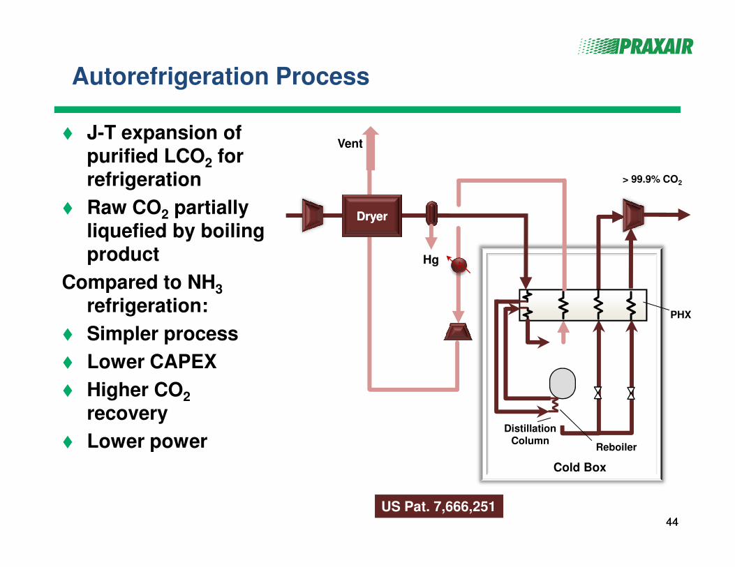
Autorefrigeration Process
� J-T expansion of purified LCO2 for refrigeration
� Raw CO2 partially
liquefied by boiling product
Compared to NH3
> 99.9% CO2
DryerDryer
Hg
Vent
4444
Compared to NH3
refrigeration:
� Simpler process
� Lower CAPEX
� Higher CO2
recovery
� Lower power
Cold Box
DistillationColumn
PHX
Reboiler
US Pat. 7,666,251
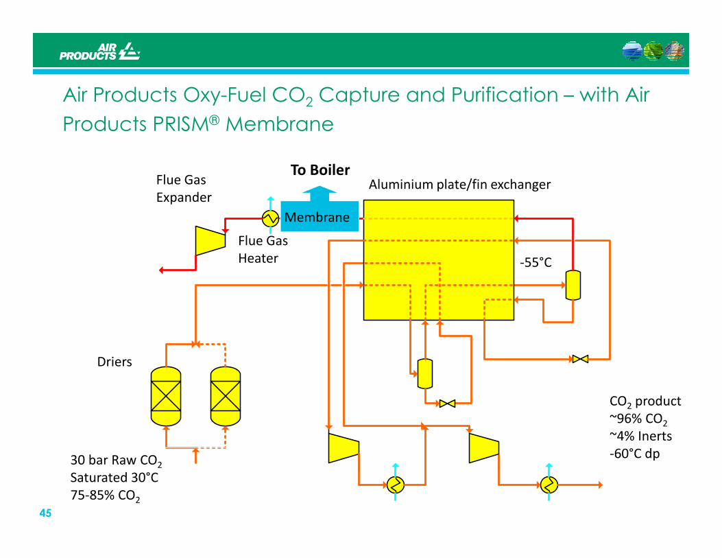
Air Products Oxy-Fuel CO2 Capture and Purification – with Air
Products PRISM® Membrane
Flue Gas
ExpanderAluminium plate/fin exchanger
Flue Gas
Heater -55°C
Membrane
To Boiler
45
Driers
CO2 product
~96% CO2
~4% Inerts
-60°C dp30 bar Raw CO2
Saturated 30°C
75-85% CO2
47
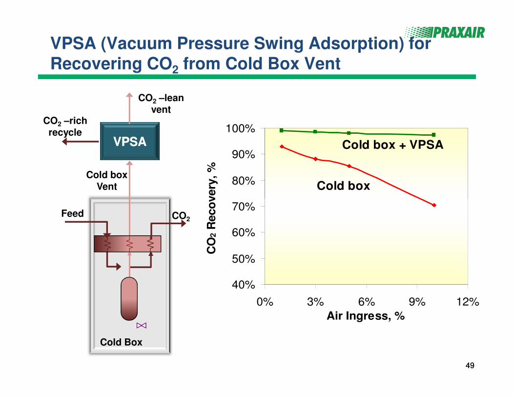
VPSA (Vacuum Pressure Swing Adsorption) for Recovering CO2 from Cold Box Vent
80%
90%
100%
Reco
very
, %
Cold box
Cold box + VPSA
Cold boxVent
VPSAVPSA
CO2 –richrecycle
CO2 –leanvent
4949
40%
50%
60%
70%
0% 3% 6% 9% 12%
Air Ingress, %
CO
2 R
eco
very
, %
Feed CO2
Cold Box
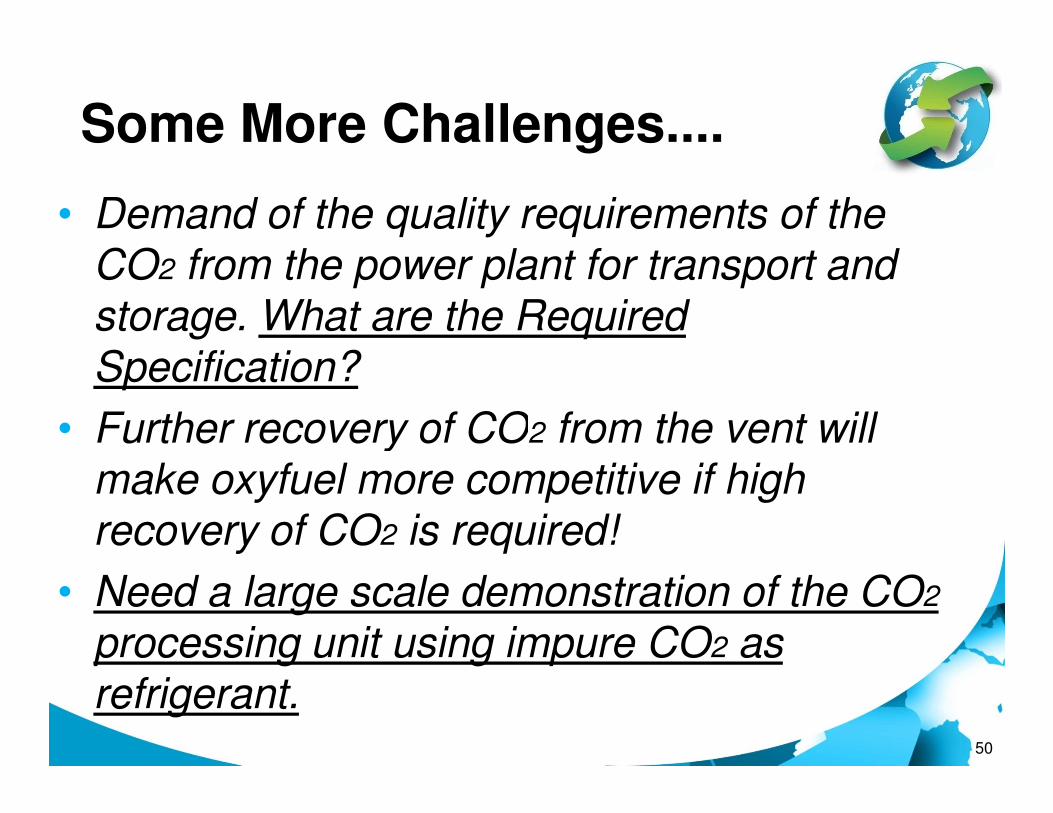
Some More Challenges....
• Demand of the quality requirements of the CO2 from the power plant for transport and storage. What are the Required Specification?
• Further recovery of CO from the vent will
50
• Further recovery of CO2 from the vent will make oxyfuel more competitive if high recovery of CO2 is required!
• Need a large scale demonstration of the CO2
processing unit using impure CO2 as refrigerant.
515
Alstom Schwarze Pumpe 2008 30MWth Lignite
Hitachi Babcock Schwarze Pumpe 2010 30MWth Lignite
IHI Callide 2011 30MWe
Alstom / AL Lacq 2009 30MWth Gas/Oil?
CIUDEN El Bierzo CFB Facility 2011 30MWth Coal
El Bierzo PC Facility 2011 20MWth Coal
Coal
CIUDEN
2008
World’s FIRST 30 MWt
full chain demonstration
at Schwarze Pumpe Pilot
2009 – Lacq –
World’s first 30MWt
retrofitted Oxy-NG
boiler2011 – CIUDEN –
World’s first 30MWt
Oxy-CFB Pilot Plant
2011 – Callide –
World’s first
30MWe retrofitted
Oxy-coal power
plant
By 2014-2018
Demonstration of
50– 300MWe full
scale power plant.
Target :
“Commercialised by 2020”
KEPCO/KOSEP - Yongdong (PC - 100MWe)
FutureGen2 - Illinois (PC - 168MWe)
Drax’s White Rose Oxyfuel Project (300MWe)
Endesa/CIUDEN - El Bierzo (CFB - 300MWe) - ???
China: 3 Oxyfuel Projects – in progress
52
1980’s
ANL/Battelle/EERC completed the first
industrial scale pilot plant
1990 - 1995
EC Joule Thermie Project
- IFRF / Doosan Babcock / Int’l Combustion
NEDO / IHI / Jcoal Project
First large scale 35MWt
Oxy-Coal Burner Retrofit
Test done by
International Combustion
1998 – 2001
CANMET
US DOE Project / B&W / Air Liquide
2003 - 2005
Vattenfall (ENCAP ++)
CS Energy / IHI Callide Project
B&W CEDF 2008 30MWth Coal
Alstom Alstom CE 2010 15MWth Coal
Doosan Babcock DBEL - MBTF 2009 40MWth Coal
2007
B&W CEDF (30MWt)
large scale burner testing started
Updated by S. Santos (20/08/12)
at Schwarze Pumpe Pilot
Plant
By the end of 2010/2011, Users (i.e. Power Plant
Operators) will have 6 burner manufacturers fully
demonstrating “Utility Size Large Scale Burners” which should
give a high level of confidence toward demonstration