
CHALLENGES OF THE SECOND SUBMARINE INTERCONNECTION … · CHALLENGES OF THE SECOND SUBMARINE...
5
Return to Session CHALLENGES OF THE SECOND SUBMARINE INTERCONNECTION BETWEEN SPAIN AND MOROCCO Ramon GRANADINO, RED ELECTRICA (Spain), [email protected] Juan PRIETO, RED ELECTRICA (Spain), [email protected] Gregorio DENCHE, RED ELECTRICA (Spain), [email protected] Fatima MANSOURI, ONE (Morocco), [email protected] Knut STENSETH, NEXANS (Norway), [email protected] Roberto COMELLINI, PRYSMIAN (Italy), [email protected] ABSTRACT A first Submarine 400 kV Electric Interconnection 28 km long was commissioned in 1997 and represented the first submarine electric line between two continents and a world record reaching a maximum depth of 615 m at that time. The power line has been in commercial operation since May 1998 serving energy market agents on the basis of bilateral short term energy contracts. The two system operators and owners REE (Spain) and ONE (Morocco) launched in 2001 a project calling for the reinforcement of the existing line by the design and construction of a new submarine link that runs in parallel with the existing one. This new circuit provides the additional exchange capacity needed but also contributes to the increase in system security and operation performances. The interconnection which is designed to transmit 700 MW with a thermal overload capability to allow a 900 MW load for 20 minutes was supplied and installed by the Consortium; Nexans Norway AS and Prysmian Cables and Systems (Italy) . KEYWORDS Submarine power cables, laying and protection techniques, spare cable operation. INTRODUCTION The electrical systems of UCTE and Maghreb were interconnected for the first time in 1997, when the first submarine link between Spain and Morocco was commissioned. The project provided for all the expected benefits of the joint operation of the interconnected systems not only in terms of emergency exchanges and access to energy markets, but also in terms of security and frequency control. The increasing use of the exchange capacity across the link and the extension of cross-border connections between Europe and Northern Africa, within the MEDRING project (Figure 1), called for the extension of the existing line to guarantee the future demands for quality and security of supply. In 2000 the Spanish and Moroccan Governments requested their Transmission System Operators RED ELECTRICA DE ESPAÑA (REE) and L’OFFICE NATIONALE DE L’ELECTRICITÉ (ONE) to reinforce the interconnection with a second parallel line. The contract for the design and construction of the link was signed on December 9, 2003 (exactly 10 years after the signing of the contract for the realisation of the first interconnection) in Casablanca between REE and ONE on one side and the consortium made by Nexans and Prysmian Cables & Systems (at that time still Pirelli Cables & Systems) on the other. The total cost for the turn-key project was 115 M€, and the interconnection has been commissioned in summer 2006. Figure 1 : Electric Mediterranean Ring, Medring The new electrical interconnection - designed for the extension of the existing Spain-Morocco 400 kV AC 4 cables link (with 1 spare cable) in order to double the power transmission capacity - consists of three power cables (paper insulated self contained oil filled) and two fibre optic cables that connect the two systems across the Straits of Gibraltar between Tarifa in Spain and Fardioua in Morocco at a maximum depth of 620 m. The total route length of the link is 31.3 km and includes 2 land sections, one on the Spanish and one on the Moroccan coast, of approximately 2 km and 0.25 km respectively. The submarine cables are terminated at the shore and linked, by means of transition joints, to the land cables, which are connected, in turn, to the terminal stations at both sides of the Straits. The new line was designed to guarantee a continuous transmission capacity of 700 MW and an emergency rated power limited to 20 minutes of 900 MW, similarly to the first interconnection. The link is operated in alternate current; however the cables used in the interconnection are designed for a possible later conversion to direct current operation, thus offering the possibility of upgrading the interconnection capacity up to 2000 MW. ENVIRONMENTAL AND SOCIAL INTEGRATION The Strait of Gibraltar is a place of great environmental
Transcript of CHALLENGES OF THE SECOND SUBMARINE INTERCONNECTION … · CHALLENGES OF THE SECOND SUBMARINE...

Return to Session
CHALLENGES OF THE SECOND SUBMARINE INTERCONNECTION BETWEEN SPAIN AND MOROCCO
Ramon GRANADINO, RED ELECTRICA (Spain), [email protected] Juan PRIETO, RED ELECTRICA (Spain), [email protected] Gregorio DENCHE, RED ELECTRICA (Spain), [email protected] Fatima MANSOURI, ONE (Morocco), [email protected] Knut STENSETH, NEXANS (Norway), [email protected] Roberto COMELLINI, PRYSMIAN (Italy), [email protected]
ABSTRACT A first Submarine 400 kV Electric Interconnection 28 km long was commissioned in 1997 and represented the first submarine electric line between two continents and a world record reaching a maximum depth of 615 m at that time. The power line has been in commercial operation since May 1998 serving energy market agents on the basis of bilateral short term energy contracts. The two system operators and owners REE (Spain) and ONE (Morocco) launched in 2001 a project calling for the reinforcement of the existing line by the design and construction of a new submarine link that runs in parallel with the existing one. This new circuit provides the additional exchange capacity needed but also contributes to the increase in system security and operation performances. The interconnection which is designed to transmit 700 MW with a thermal overload capability to allow a 900 MW load for 20 minutes was supplied and installed by the Consortium; Nexans Norway AS and Prysmian Cables and Systems (Italy) .
KEYWORDS Submarine power cables, laying and protection techniques, spare cable operation.
INTRODUCTION The electrical systems of UCTE and Maghreb were interconnected for the first time in 1997, when the first submarine link between Spain and Morocco was commissioned. The project provided for all the expected benefits of the joint operation of the interconnected systems not only in terms of emergency exchanges and access to energy markets, but also in terms of security and frequency control. The increasing use of the exchange capacity across the link and the extension of cross-border connections between Europe and Northern Africa, within the MEDRING project (Figure 1), called for the extension of the existing line to guarantee the future demands for quality and security of supply.
In 2000 the Spanish and Moroccan Governments requested their Transmission System Operators RED ELECTRICA DE ESPAÑA (REE) and L’OFFICE NATIONALE DE L’ELECTRICITÉ (ONE) to reinforce the interconnection with a second parallel line. The contract for the design and construction of the link was signed on December 9, 2003 (exactly 10 years after the signing of the contract for the realisation of the first interconnection) in Casablanca
between REE and ONE on one side and the consortium made by Nexans and Prysmian Cables & Systems (at that time still Pirelli Cables & Systems) on the other. The total cost for the turn-key project was 115 M€, and the interconnection has been commissioned in summer 2006.
Figure 1 : Electric Mediterranean Ring, Medring
The new electrical interconnection - designed for the extension of the existing Spain-Morocco 400 kV AC 4 cables link (with 1 spare cable) in order to double the power transmission capacity - consists of three power cables (paper insulated self contained oil filled) and two fibre optic cables that connect the two systems across the Straits of Gibraltar between Tarifa in Spain and Fardioua in Morocco at a maximum depth of 620 m. The total route length of the link is 31.3 km and includes 2 land sections, one on the Spanish and one on the Moroccan coast, of approximately 2 km and 0.25 km respectively. The submarine cables are terminated at the shore and linked, by means of transition joints, to the land cables, which are connected, in turn, to the terminal stations at both sides of the Straits.
The new line was designed to guarantee a continuous transmission capacity of 700 MW and an emergency rated power limited to 20 minutes of 900 MW, similarly to the first interconnection. The link is operated in alternate current; however the cables used in the interconnection are designed for a possible later conversion to direct current operation, thus offering the possibility of upgrading the interconnection capacity up to 2000 MW.
ENVIRONMENTAL AND SOCIAL INTEGRATION The Strait of Gibraltar is a place of great environmental

Return to Session
value. Due to its location, it is one of the most visited places in the world for bird watching since is the main migration corridor between Europe and Africa.
Some of the land areas in the Straits are protected by European directives, inside “Natura 2000”. Both REE in Spain and ONE in Morocco have developed a number of actions to promote the participation of various social, environmental and institutional agents in the analysis and definition of the project compensation measures, defined in the Environmental Impact Assessment Evaluation procedures.
Compensation measures, in contrast to preventive and corrective measures, must not focus in reducing the direct consequences from construction, but to mitigate its possible diffuse effect on the ecosystem. Compensation measures projects, managed in Spain for this project through Migres Foundation, are aimed at strengthening the weakest elements of the ecosystem in order to reduce their fragility, minimizing the indirect loss of habitats and both the direct and indirect impact over the population because of the infrastructure.
In the Spanish side, for this second circuit between Spain and Morocco a Social Acceptance Program has been developed with the following objectives:
- Integrate company presence in the social and institutional fabric.
- Achieve maximum institutional and social consensus. - Respond to information demand and maintain
information transparency. - Facilitate the understanding of the project necessity. - Reach positive agreements finding a balance between
general needs of the affected municipality and the real possibilities of the project.
LAND AND MARINE CABLE ROUTES In the land sections the new circuit goes parallel (10 m distance between axes) to the existing one. The cables are in a horizontal configuration, in a 2.5 m wide and 2 m deep trench, under concrete tiles as protection. The length of these sections is: 2.05 km in the Spanish side (with a total of 12 joints, one each 410 m) and 0.25 km in Morocco.
For the submarine section, in 2002 a new corridor west from the first circuit was studied using survey vessels to identify bathymetry and bottom characteristics. Three new routes (one for each power cable) were selected with the premises of minimising cable length while maximizing the length in sand, bottom stability and optimizing crossings.
The maximum depth is 620 m, and the length of the western cable is 29.7 km while for the eastern is 28.1 km. Average separation between circuits is 500 m (minimum 210 m).
LAND AND SUBMARINE CABLE DESIGNS The new link is made up with three 400kV AC power cables, also qualified for ±450kV DC operation. Two telecommunication cables, with 48 fibre optics each, have also been installed, both for system control and data transmission.
The submarine power cable design is identical to the one
that has been qualified and type tested for the first project and which has proven full reliability. The submarine cable, shown in the sketch below, is a SCFF, 800 mm² copper conductor (2) incorporating a 24mm oil duct (1), with lead sheath (6) and double layer of copper wires armour (10, 13). The cable has an overall diameter of 139mm, a mass of 56kg/m (in air) and is designed to withstand a tensile load of almost 40t and an internal oil pressure of 18 bar.
ID Component Material Outer Diam.
[mm] 1 Oil duct 24 2 Conductor Copper 41 3 Conductor screen Carbon black paper 4 Insulation Paper tapes 91 5 Insulation screen Carbon black paper 6 Metallic sheath Lead alloy 103 7 Reinforcement Bronze tapes 8 Corrosion
protection low density polyethylene
9 Antiteredo protection
polyester /copper tapes
114
10 Bedding Polyester tapes 11 Armour inner layer H.D. copper flat wires 12 Armour protection polypropylene yarn 13 Armour outer layer H.D. copper flat wires 14 Outer serving polypropylene yarn 139 Prysmian manufactured two submarine cables at its Arco Felice (Napoli) plant in Italy while Nexans supplied the third from the Halden plant, in Norway.
The underground power cables used for the connection from the shore to the overhead line are designed to constitute a single electrical system and a single oil-feeding system, together with the submarine cables.
The cable for the land sections in Spain and Morocco, route lengths 2050 metre and 250 metre respectively, has a conductor size of 1600 mm2.
The copper conductor of the land cables has a cross-sectional area of 1600mm² to ensure the same transmission capacity as the submarine cable despite the more severe thermal conditions with respect to the submarine section. The outer diameter for land cables is 122mm and the weight is 42kg/m.
In Spain the land cable is partitioned into four minor sections connected by means of three sectionalised straight joints. Each section is insulated from each other and two earth continuity conductors are installed along the cables -

Return to Session
“Repeated Single Point Bonding Method”.
In Morocco the land cable is directly bonded and grounded at the transition joint (land-/submarine cable) and sectionalised at termination. Two earth continuity conductors are installed along the cables.
The land cables are terminated in outdoor sealing ends at both ends.
Land Cable Design can be seen in the following sketch:
ID Component Nominal
thickness Nominal diameter
1 Fluid duct 24
2 Conductor, Annealed shaped copper wires 52.1
3 Conductor screen, Carbon black paper
4 Insulation, specie pure pulp washed paper 23.4
5 Insulation screen 6 Lead sheath, Lead alloy 4 109.5
7 Bedding, Conductive/ semiconductive tape 0.25
8 Longitudinal reinforcement, stainless steel wire 0.4
9 Bedding, Conductive/ semiconductive tape 0.25
10 Reinforcement, Stainless steel tape 2x0.20
11 Bedding, Semi-conductive Polyester tape 0.15
12 Corrosion Protection, High Density Polyethylene 4.8 122
The land cable was manufactured and installed by Nexans.
The submarine optical cables - used to carry all necessary control and protection signals of the interconnection itself and other specific communication signals - were laid in bundle configuration with the outer power cables. They are mono mode type either loose tube single armoured or slotted core double armoured. The two 48 multi-fibre fibre optic cables contain 42 f.o. G.652 type and 6 f.o. G.655 type (ITU-T recommendations) and are specifically designed for repeaterless systems and ensure proper light-wave information transmission.
PUMPING PLANT The link includes a second and independent oil-feeding system for the three new cables, which is fully compatible with the facilities already existing and provided with the previous line.
To fluid feed and pressurize the cable link two PLC controlled high redundancy pumping plants are installed, one in Morocco and one in Spain. One plant alone is capable to maintain normal operation requirement of the cable system, while the other can be shut down for service.
Additionally, the pumping plants are also designed to feed a cable with a severe mechanical damage for a prolonged time, saving the cable until a subsequent repair can be accomplished.
Main feature of the feeding system
- Fluid capacity, each plant: 15000 l - Max. fluid flow/feeding: 1500 l/h - Feeding pressure at sea level: 16-18 bar - The pumping plant is designed, supplied and installed by
Nexans.
The pumping stations are designed to secure safe operation under all possible conditions, even in the absence of ordinary auxiliary power supply for ten days.
TEMPERATURE MONITORING SYSTEM A Distributed Temperature Sensing – DTS – system is installed on the new link to ensure that maximum operational conductor temperature not will be exceeded and to detect/localize any cable “hot spots” along the cable route. The system is also an application to safely maximizing the transmission capacity of cable network
The DTS measures the temperature of the cable, using fibres in a fibre optical (FO) cable as temperature sensor. The FO-cable is located on the surface of the power cable. On bases of the DTS measured surface temperature a program installed (PLC) calculates the conductor temperature according to IEC 60287. The calculated conductor temperature is presented on the DTS PC screen.
Return to Session
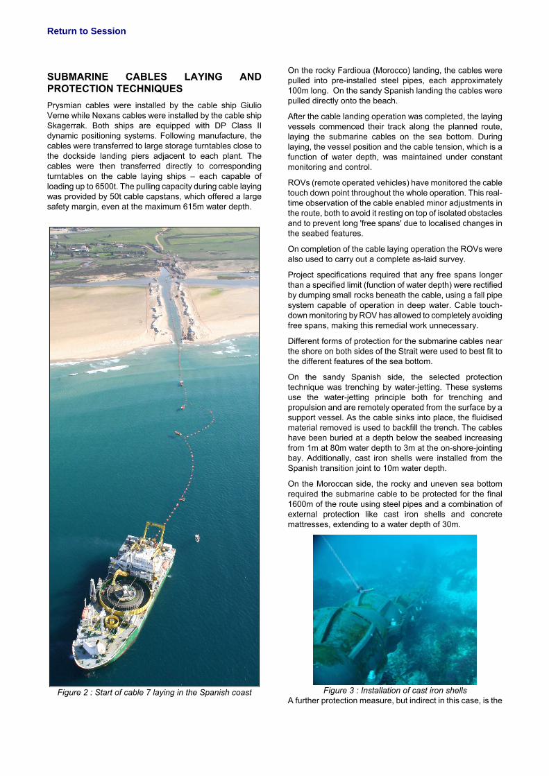
SUBMARINE CABLES LAYING AND PROTECTION TECHNIQUES Prysmian cables were installed by the cable ship Giulio Verne while Nexans cables were installed by the cable ship Skagerrak. Both ships are equipped with DP Class II dynamic positioning systems. Following manufacture, the cables were transferred to large storage turntables close to the dockside landing piers adjacent to each plant. The cables were then transferred directly to corresponding turntables on the cable laying ships – each capable of loading up to 6500t. The pulling capacity during cable laying was provided by 50t cable capstans, which offered a large safety margin, even at the maximum 615m water depth.
Figure 2 : Start of cable 7 laying in the Spanish coast
On the rocky Fardioua (Morocco) landing, the cables were pulled into pre-installed steel pipes, each approximately 100m long. On the sandy Spanish landing the cables were pulled directly onto the beach.
After the cable landing operation was completed, the laying vessels commenced their track along the planned route, laying the submarine cables on the sea bottom. During laying, the vessel position and the cable tension, which is a function of water depth, was maintained under constant monitoring and control.
ROVs (remote operated vehicles) have monitored the cable touch down point throughout the whole operation. This real-time observation of the cable enabled minor adjustments in the route, both to avoid it resting on top of isolated obstacles and to prevent long 'free spans' due to localised changes in the seabed features.
On completion of the cable laying operation the ROVs were also used to carry out a complete as-laid survey.
Project specifications required that any free spans longer than a specified limit (function of water depth) were rectified by dumping small rocks beneath the cable, using a fall pipe system capable of operation in deep water. Cable touch-down monitoring by ROV has allowed to completely avoiding free spans, making this remedial work unnecessary.
Different forms of protection for the submarine cables near the shore on both sides of the Strait were used to best fit to the different features of the sea bottom.
On the sandy Spanish side, the selected protection technique was trenching by water-jetting. These systems use the water-jetting principle both for trenching and propulsion and are remotely operated from the surface by a support vessel. As the cable sinks into place, the fluidised material removed is used to backfill the trench. The cables have been buried at a depth below the seabed increasing from 1m at 80m water depth to 3m at the on-shore-jointing bay. Additionally, cast iron shells were installed from the Spanish transition joint to 10m water depth.
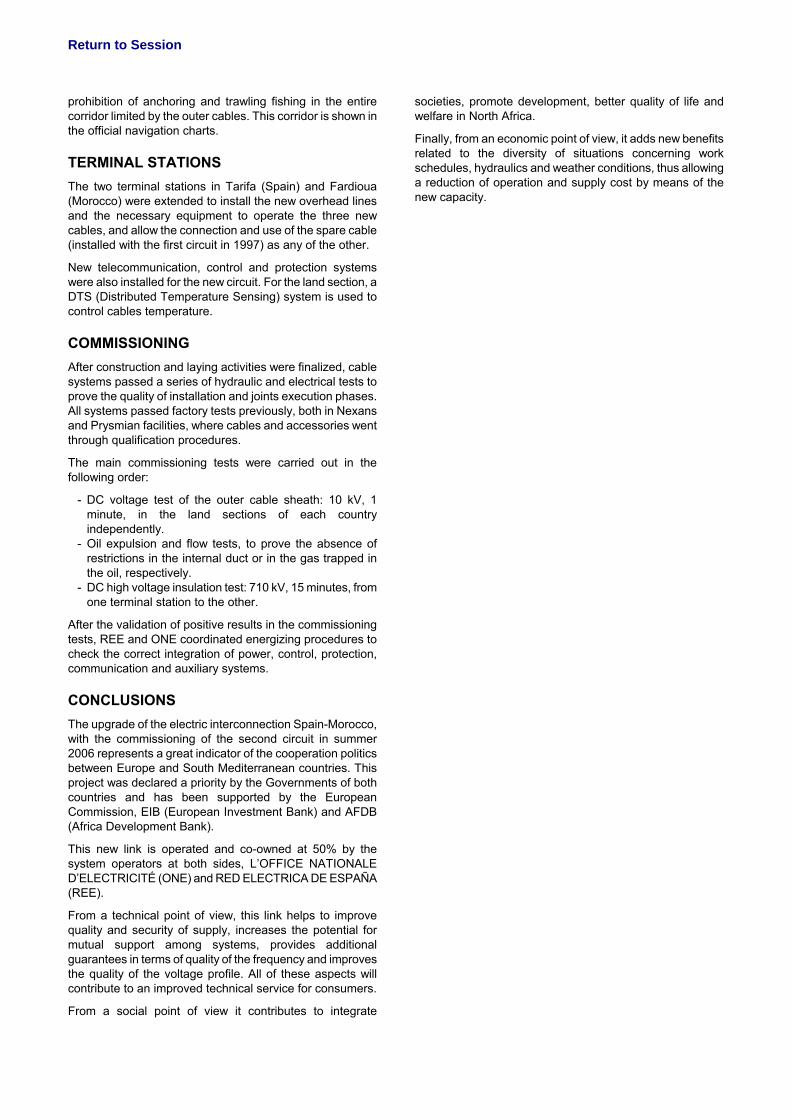
On the Moroccan side, the rocky and uneven sea bottom required the submarine cable to be protected for the final 1600m of the route using steel pipes and a combination of external protection like cast iron shells and concrete mattresses, extending to a water depth of 30m.
Figure 3 : Installation of cast iron shells
A further protection measure, but indirect in this case, is the
Return to Session
prohibition of anchoring and trawling fishing in the entire corridor limited by the outer cables. This corridor is shown in the official navigation charts.
TERMINAL STATIONS The two terminal stations in Tarifa (Spain) and Fardioua (Morocco) were extended to install the new overhead lines and the necessary equipment to operate the three new cables, and allow the connection and use of the spare cable (installed with the first circuit in 1997) as any of the other.
New telecommunication, control and protection systems were also installed for the new circuit. For the land section, a DTS (Distributed Temperature Sensing) system is used to control cables temperature.
COMMISSIONING After construction and laying activities were finalized, cable systems passed a series of hydraulic and electrical tests to prove the quality of installation and joints execution phases. All systems passed factory tests previously, both in Nexans and Prysmian facilities, where cables and accessories went through qualification procedures.
The main commissioning tests were carried out in the following order:
- DC voltage test of the outer cable sheath: 10 kV, 1 minute, in the land sections of each country independently.
- Oil expulsion and flow tests, to prove the absence of restrictions in the internal duct or in the gas trapped in the oil, respectively.
- DC high voltage insulation test: 710 kV, 15 minutes, from one terminal station to the other.
After the validation of positive results in the commissioning tests, REE and ONE coordinated energizing procedures to check the correct integration of power, control, protection, communication and auxiliary systems.
CONCLUSIONS The upgrade of the electric interconnection Spain-Morocco, with the commissioning of the second circuit in summer 2006 represents a great indicator of the cooperation politics between Europe and South Mediterranean countries. This project was declared a priority by the Governments of both countries and has been supported by the European Commission, EIB (European Investment Bank) and AFDB (Africa Development Bank).
This new link is operated and co-owned at 50% by the system operators at both sides, L’OFFICE NATIONALE D’ELECTRICITÉ (ONE) and RED ELECTRICA DE ESPAÑA (REE).
From a technical point of view, this link helps to improve quality and security of supply, increases the potential for mutual support among systems, provides additional guarantees in terms of quality of the frequency and improves the quality of the voltage profile. All of these aspects will contribute to an improved technical service for consumers.
From a social point of view it contributes to integrate
societies, promote development, better quality of life and welfare in North Africa.
Finally, from an economic point of view, it adds new benefits related to the diversity of situations concerning work schedules, hydraulics and weather conditions, thus allowing a reduction of operation and supply cost by means of the new capacity.


![[Locat00] Submarine Landslides Advances and Challenges](https://static.fdocuments.us/doc/165x107/5476f099b4af9f48248b4607/locat00-submarine-landslides-advances-and-challenges.jpg)