Ch.01 inroduction
8
1/11/2016 1 01. Introduction System Dynamics and Control 1.01 Introduction HCM City Univ. of Technology, Faculty of Mechanical Engineering Nguyen Tan Tien Learning Outcome After completing this chapter, the student will be able to • Define a control system and describe some applications • Describe historical developments leading to modern day control theory • Describe the basic features and configurations of control systems • Describe control systems analysis and design objectives • Describe a control system’s design process • Describe the benefit from studying control systems System Dynamics and Control 1.02 Introduction HCM City Univ. of Technology, Faculty of Mechanical Engineering Nguyen Tan Tien § 1 . Introduction - Control System Definition A control system consists of subsystems and processes (or plants) assembled for the purpose of obtaining a desired output with desired performance, given a specified input - Ex .: elevator control system System Dynamics and Control 1.03 Introduction HCM City Univ. of Technology, Faculty of Mechanical Engineering Nguyen Tan Tien § 1 . Introduction Early elevators were controlled by hand ropes or an elevator operator Today, elevators are fully automatic, using control systems to regulate position and velocity System Dynamics and Control 1.04 Introduction HCM City Univ. of Technology, Faculty of Mechanical Engineering Nguyen Tan Tien § 2 . A History of Control Systems B.C.200 Greece Float regulator mechanism B.C.50 Middle East Water clock 1600 Cornelis Drebbel, Holland First feedback system Temperature regulator 1462-1727 Sir Isaac Newton Mathematical modeling 1685-1731 Brook Taylor Taylor series 1700 Dennis Papin Pressure regulator for steam boiler System Dynamics and Control 1.05 Introduction HCM City Univ. of Technology, Faculty of Mechanical Engineering Nguyen Tan Tien § 2 . A History of Control Systems 1749-1827 Pierse Simon Laplace Laplace Transform 1769 James Watt First automatic controller Flyball governer 1765 I. Polzunov, Soviet Union First level regulator system 1831-1907 Edward John Routh Routh criterion 1859-1925 Oliver Heaviside Mathematical analysis 1868 J.C. Maxwell Mathematical theory for control system System Dynamics and Control 1.06 Introduction HCM City Univ. of Technology, Faculty of Mechanical Engineering Nguyen Tan Tien
-
Upload
nguyentantien -
Category
Engineering
-
view
266 -
download
0
Transcript of Ch.01 inroduction

1/11/2016
1
01. Introduction
System Dynamics and Control 1.01 Introduction
HCM City Univ. of Technology, Faculty of Mechanical Engineering Nguyen Tan Tien
Learning Outcome
After completing this chapter, the student will be able to
• Define a control system and describe some applications
• Describe historical developments leading to modern day
control theory
• Describe the basic features and configurations of control
systems
• Describe control systems analysis and design objectives
• Describe a control system’s design process
• Describe the benefit from studying control systems
System Dynamics and Control 1.02 Introduction
HCM City Univ. of Technology, Faculty of Mechanical Engineering Nguyen Tan Tien
§1.Introduction
- Control System Definition
A control system consists of subsystems and processes (or
plants) assembled for the purpose of obtaining a desired output
with desired performance, given a specified input
- Ex.: elevator control system
System Dynamics and Control 1.03 Introduction
HCM City Univ. of Technology, Faculty of Mechanical Engineering Nguyen Tan Tien
§1.Introduction
Early elevators were
controlled by hand ropes
or an elevator operator
Today, elevators are fully automatic,
using control systems to regulate
position and velocity
System Dynamics and Control 1.04 Introduction
HCM City Univ. of Technology, Faculty of Mechanical Engineering Nguyen Tan Tien
§2.A History of Control Systems
B.C.200 Greece
Float regulator mechanism
B.C.50 Middle East
Water clock
1600 Cornelis Drebbel, Holland
First feedback system
Temperature regulator
1462-1727 Sir Isaac Newton
Mathematical modeling
1685-1731 Brook Taylor
Taylor series
1700 Dennis Papin
Pressure regulator for steam boiler
System Dynamics and Control 1.05 Introduction
HCM City Univ. of Technology, Faculty of Mechanical Engineering Nguyen Tan Tien
§2.A History of Control Systems
1749-1827 Pierse Simon Laplace
Laplace Transform
1769 James Watt
First automatic controller
Flyball governer
1765 I. Polzunov, Soviet Union
First level regulator system
1831-1907 Edward John Routh
Routh criterion
1859-1925 Oliver Heaviside
Mathematical analysis
1868 J.C. Maxwell
Mathematical theory for control system
System Dynamics and Control 1.06 Introduction
HCM City Univ. of Technology, Faculty of Mechanical Engineering Nguyen Tan Tien

1/11/2016
2
§2.A History of Control Systems
1890’ Lyapunov, Soviet Union
Stability theory
1930’ Nyquist, Bode, Black; Bell Telephone Lab
Electronic feedback amplifier
1889-1976 Harry Nyquist
Nyquist criterion
1898-1981 Harold Black
Negative feedback amp
1905-1982 Hendrik Bode
Bode diagram
WWII period Automatic airplane pilot; Gun-positioning system,
radar; Antenna control system; Military systems
System Dynamics and Control 1.07 Introduction
HCM City Univ. of Technology, Faculty of Mechanical Engineering Nguyen Tan Tien
§2.A History of Control Systems
Post War Frequency domain analysis
Laplace transform method
1903-1957 John Von Neumann
Basic operation of digital computer
1950’ Root locus method
Computer age open (digital control)
Space age (Sputnik, Soviet Union)
Maximum principle (Pontryagin)
Optimal control
Adaptive control system (Draper)
1960’ Dynamic programming (Bellman)
State space method
System Dynamics and Control 1.08 Introduction
HCM City Univ. of Technology, Faculty of Mechanical Engineering Nguyen Tan Tien
Sputnik, 1957
§2.A History of Control Systems
1970’ Microprocessor based control system
Digital control system
1980 Neural network
Artificial Intelligent
Fuzzy control
Predictive control
Doyle & Stein: LQG / LTR
Remote diagnostic control system
System Dynamics and Control 1.09 Introduction
HCM City Univ. of Technology, Faculty of Mechanical Engineering Nguyen Tan Tien
§3.System Configurations
- Open-Loop Systems
- Closed-Loop Systems
- Computer-Controlled Systems
System Dynamics and Control 1.10 Introduction
HCM City Univ. of Technology, Faculty of Mechanical Engineering Nguyen Tan Tien
§4.Analysis and Design Objectives
- Analysis: determine a system’s performance
- Design: create or change a system’s performance
- A control system is dynamic → It responds to an input by
undergoing a transient response before reaching a steady-state
response that generally resembles the input
- Three major objectives of systems analysis and design
• Producing the desired transient response
• Reducing steady-state error
• Achieving stability
Other design concerns
• Cost
• The sensitivity of system performance to changes in
parameters
System Dynamics and Control 1.11 Introduction
HCM City Univ. of Technology, Faculty of Mechanical Engineering Nguyen Tan Tien
𝑥 𝑡 =𝑏
𝑎+ 𝑥 0 −
𝑏
𝑎𝑒−𝑎𝑡 = 𝑥 0 𝑒−𝑎𝑡 +
𝑏
𝑎1 − 𝑒−𝑎𝑡
§4.Analysis and Design Objectives
- Response
The solution of 𝑥 + 𝑎𝑥 = 𝑏
𝑥 𝑡 =𝑏
𝑎+ 𝑥 0 −
𝑏
𝑎𝑒−𝑎𝑡
𝑥 𝑡 = 𝑥 0 𝑒−𝑎𝑡 +𝑏
𝑎1 − 𝑒−𝑎𝑡
Response
• Steady-state: the part of the response that remains with time
• Transient: the part of the response that disappears with time
• Free: the part of the response that depends on the initial conditions
• Forced: the part of the response due to the forcing function
System Dynamics and Control 1.12 Introduction
or
HCM City Univ. of Technology, Faculty of Mechanical Engineering Nguyen Tan Tien
1/11/2016
3
𝑥 𝑡 =𝑏
𝑎+ 𝑥 0 −
𝑏
𝑎𝑒−𝑎𝑡 = 𝑥 0 𝑒−𝑎𝑡 +
𝑏
𝑎1 − 𝑒−𝑎𝑡
§4.Analysis and Design Objectives
- Stability
The solution of 𝑥 + 𝑎𝑥 = 𝑏
𝑥 𝑡 = 𝑥 0 𝑒−𝑎𝑡 +𝑏
𝑎1 − 𝑒−𝑎𝑡
• Unstable: the free response approaches ∞ as 𝑡 → ∞
• Stable: the free response approaches 0
• Neutral stability: the borderline between stable and unstable.
The free response does not approach both ∞ and 0
- Other considerations
• Finances
• Robustness
System Dynamics and Control 1.13 Introduction
HCM City Univ. of Technology, Faculty of Mechanical Engineering Nguyen Tan Tien
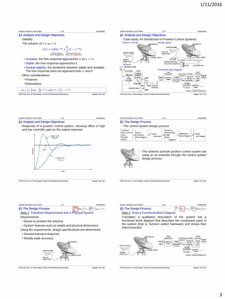
§4.Analysis and Design Objectives
- Case study: An Introduction to Position Control Systems
Scheme
System concept Design layout
Functional block diagram
System Dynamics and Control 1.14 Introduction
HCM City Univ. of Technology, Faculty of Mechanical Engineering Nguyen Tan Tien
§4.Analysis and Design Objectives
- Response of a position control system, showing effect of high
and low controller gain on the output response
System Dynamics and Control 1.15 Introduction
HCM City Univ. of Technology, Faculty of Mechanical Engineering Nguyen Tan Tien
§5.The Design Process
- The control system design process
- The antenna azimuth position control system are
using as an example through the control system
design process
System Dynamics and Control 1.16 Introduction
HCM City Univ. of Technology, Faculty of Mechanical Engineering Nguyen Tan Tien
§5.The Design Process
Step 1: Transform Requirements Into a Physical System
Requirements
• Desire to position the antenna
• System features such as weight and physical dimensions
Using the requirements, design specifications are determined
• Desired transient response
• Steady-state accuracy
System Dynamics and Control 1.17 Introduction
HCM City Univ. of Technology, Faculty of Mechanical Engineering Nguyen Tan Tien
§5.The Design Process
Step 2: Draw a Functional Block Diagram
Translates a qualitative description of the system into a
functional block diagram that describes the component parts of
the system (that is, function and/or hardware) and shows their
interconnection
System Dynamics and Control 1.18 Introduction
HCM City Univ. of Technology, Faculty of Mechanical Engineering Nguyen Tan Tien
1/11/2016
4
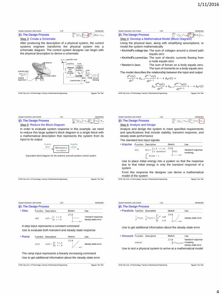
§5.The Design Process
Step 3: Create a Schematic
After producing the description of a physical system, the control
systems engineer transforms the physical system into a
schematic diagram. The control system designer can begin with
the physical description to derive a schematic
System Dynamics and Control 1.19 Introduction
HCM City Univ. of Technology, Faculty of Mechanical Engineering Nguyen Tan Tien
§5.The Design Process
Step 4: Develop a Mathematical Model (Block Diagram)
Using the physical laws, along with simplifying assumptions, to
model the system mathematically
• Kirchhoff’svoltage law The sum of voltages around a closed path
equals zero
• Kirchhoff’scurrent law The sum of electric currents flowing from
a node equals zero
• Newton’s laws The sum of forces on a body equals zero,
The sum of moments on a body equals zero
The model describes the relationship between the input and output
𝑑𝑛𝑐(𝑡)
𝑑𝑡𝑛+ 𝑑𝑛−1
𝑑𝑛−1𝑐(𝑡)
𝑑𝑡𝑛−1+⋯+ 𝑑0𝑐 𝑡 =
𝑏𝑚𝑑𝑚𝑢(𝑡)
𝑑𝑡𝑚+ 𝑏𝑚−1
𝑑𝑚−1𝑢(𝑡)
𝑑𝑡𝑚−1+⋯+ 𝑏0𝑟 𝑡
System Dynamics and Control 1.20 Introduction
HCM City Univ. of Technology, Faculty of Mechanical Engineering Nguyen Tan Tien
§5.The Design Process
Step 5: Reduce the Block Diagram
In order to evaluate system response in this example, we need
to reduce this large system’s block diagram to a single block with
a mathematical description that represents the system from its
input to its output
Equivalent block diagram for the antenna azimuth position control system
System Dynamics and Control 1.21 Introduction
HCM City Univ. of Technology, Faculty of Mechanical Engineering Nguyen Tan Tien
§5.The Design Process
Step 6: Analyze and Design
Analyze and design the system to meet specified requirements
and specifications that include stability, transient response, and
steady-state performance
The standard test input signals
• Impulse
Use to place initial energy into a system so that the response
due to that initial energy is only the transient response of a
system
From this response the designer can derive a mathematical
model of the system
System Dynamics and Control 1.22 Introduction
HCM City Univ. of Technology, Faculty of Mechanical Engineering Nguyen Tan Tien
§5.The Design Process
• Step
A step input represents a constant command
Use to evaluate both transient and steady-state response
• Ramp
The ramp input represents a linearly increasing command
Use to get additional information about the steady-state error
System Dynamics and Control 1.23 Introduction
HCM City Univ. of Technology, Faculty of Mechanical Engineering Nguyen Tan Tien
§5.The Design Process
• Parabola
Use to get additional information about the steady-state error
• Sinusoid
Use to test a physical system to arrive at a mathematical model
System Dynamics and Control 1.24 Introduction
HCM City Univ. of Technology, Faculty of Mechanical Engineering Nguyen Tan Tien
1/11/2016
5
§6.Computer-Aided Design
- MATLAB
- LabVIEW
System Dynamics and Control 1.25 Introduction
HCM City Univ. of Technology, Faculty of Mechanical Engineering Nguyen Tan Tien
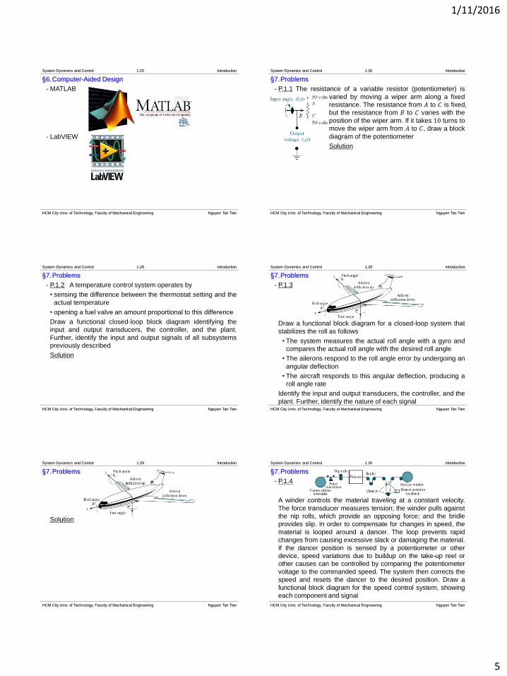
§7.Problems
- P.1.1 The resistance of a variable resistor (potentiometer) is
varied by moving a wiper arm along a fixed
resistance. The resistance from 𝐴 to 𝐶 is fixed,
but the resistance from 𝐵 to 𝐶 varies with the
position of the wiper arm. If it takes 10 turns to
move the wiper arm from 𝐴 to 𝐶, draw a block
diagram of the potentiometer
Solution
System Dynamics and Control 1.26 Introduction
HCM City Univ. of Technology, Faculty of Mechanical Engineering Nguyen Tan Tien
§7.Problems
- P.1.2 A temperature control system operates by
• sensing the difference between the thermostat setting and the
actual temperature
• opening a fuel valve an amount proportional to this difference
Draw a functional closed-loop block diagram identifying the
input and output transducers, the controller, and the plant.
Further, identify the input and output signals of all subsystems
previously described
Solution
System Dynamics and Control 1.28 Introduction
HCM City Univ. of Technology, Faculty of Mechanical Engineering Nguyen Tan Tien
§7.Problems
- P.1.3
Draw a functional block diagram for a closed-loop system that
stabilizes the roll as follows
• The system measures the actual roll angle with a gyro and
compares the actual roll angle with the desired roll angle
• The ailerons respond to the roll angle error by undergoing an
angular deflection
• The aircraft responds to this angular deflection, producing a
roll angle rate
Identify the input and output transducers, the controller, and the
plant. Further, identify the nature of each signal
System Dynamics and Control 1.28 Introduction
HCM City Univ. of Technology, Faculty of Mechanical Engineering Nguyen Tan Tien
§7.Problems
Solution
System Dynamics and Control 1.29 Introduction
HCM City Univ. of Technology, Faculty of Mechanical Engineering Nguyen Tan Tien
§7.Problems
- P.1.4
A winder controls the material traveling at a constant velocity.
The force transducer measures tension; the winder pulls against
the nip rolls, which provide an opposing force; and the bridle
provides slip. In order to compensate for changes in speed, the
material is looped around a dancer. The loop prevents rapid
changes from causing excessive slack or damaging the material.
If the dancer position is sensed by a potentiometer or other
device, speed variations due to buildup on the take-up reel or
other causes can be controlled by comparing the potentiometer
voltage to the commanded speed. The system then corrects the
speed and resets the dancer to the desired position. Draw a
functional block diagram for the speed control system, showing
each component and signal
System Dynamics and Control 1.30 Introduction
HCM City Univ. of Technology, Faculty of Mechanical Engineering Nguyen Tan Tien
1/11/2016
6
§7.Problems
Solution
System Dynamics and Control 1.31 Introduction
HCM City Univ. of Technology, Faculty of Mechanical Engineering Nguyen Tan Tien
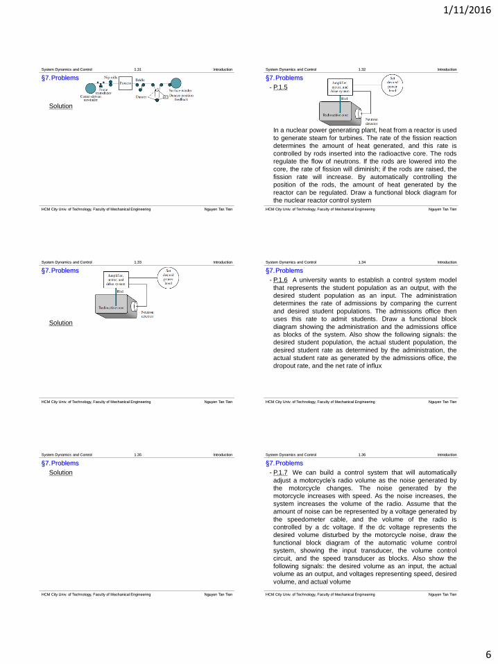
§7.Problems
- P.1.5
In a nuclear power generating plant, heat from a reactor is used
to generate steam for turbines. The rate of the fission reaction
determines the amount of heat generated, and this rate is
controlled by rods inserted into the radioactive core. The rods
regulate the flow of neutrons. If the rods are lowered into the
core, the rate of fission will diminish; if the rods are raised, the
fission rate will increase. By automatically controlling the
position of the rods, the amount of heat generated by the
reactor can be regulated. Draw a functional block diagram for
the nuclear reactor control system
System Dynamics and Control 1.32 Introduction
HCM City Univ. of Technology, Faculty of Mechanical Engineering Nguyen Tan Tien
§7.Problems
Solution
System Dynamics and Control 1.33 Introduction
HCM City Univ. of Technology, Faculty of Mechanical Engineering Nguyen Tan Tien
§7.Problems
- P.1.6 A university wants to establish a control system model
that represents the student population as an output, with the
desired student population as an input. The administration
determines the rate of admissions by comparing the current
and desired student populations. The admissions office then
uses this rate to admit students. Draw a functional block
diagram showing the administration and the admissions office
as blocks of the system. Also show the following signals: the
desired student population, the actual student population, the
desired student rate as determined by the administration, the
actual student rate as generated by the admissions office, the
dropout rate, and the net rate of influx
System Dynamics and Control 1.34 Introduction
HCM City Univ. of Technology, Faculty of Mechanical Engineering Nguyen Tan Tien
§7.Problems
Solution
System Dynamics and Control 1.35 Introduction
HCM City Univ. of Technology, Faculty of Mechanical Engineering Nguyen Tan Tien
§7.Problems
- P.1.7 We can build a control system that will automatically
adjust a motorcycle’s radio volume as the noise generated by
the motorcycle changes. The noise generated by the
motorcycle increases with speed. As the noise increases, the
system increases the volume of the radio. Assume that the
amount of noise can be represented by a voltage generated by
the speedometer cable, and the volume of the radio is
controlled by a dc voltage. If the dc voltage represents the
desired volume disturbed by the motorcycle noise, draw the
functional block diagram of the automatic volume control
system, showing the input transducer, the volume control
circuit, and the speed transducer as blocks. Also show the
following signals: the desired volume as an input, the actual
volume as an output, and voltages representing speed, desired
volume, and actual volume
System Dynamics and Control 1.36 Introduction
HCM City Univ. of Technology, Faculty of Mechanical Engineering Nguyen Tan Tien

1/11/2016
7
§7.Problems
Solution
System Dynamics and Control 1.37 Introduction
HCM City Univ. of Technology, Faculty of Mechanical Engineering Nguyen Tan Tien
§7.Problems
- P.1.8 Your bathtub at home is a control system that keeps the
water level constant. A constant flow from the tap yields a
constant water level, because the flow rate through the drain
increases as the water level increases, and decreases as the
water level decreases. After equilibrium has been reached, the
level can be controlled by controlling the input flow rate. A low
input flow rate yields a lower level, while a higher input flow rate
yields a higher level
a.Sketch a control system that uses this principle to precisely
control the fluid level in a tank. Show the intake and drain
valves, the tank, any sensors and transducers, and the
interconnection of all components
b.Draw a functional block diagram of the system, identifying the
input and output signals of each block
System Dynamics and Control 1.38 Introduction
HCM City Univ. of Technology, Faculty of Mechanical Engineering Nguyen Tan Tien
§7.Problems
Solution
a.
System Dynamics and Control 1.39 Introduction
HCM City Univ. of Technology, Faculty of Mechanical Engineering Nguyen Tan Tien
§7.Problems
b.
System Dynamics and Control 1.40 Introduction
HCM City Univ. of Technology, Faculty of Mechanical Engineering Nguyen Tan Tien
§7.Problems
- P.1.11
The vertical position, 𝑥(𝑡), of the grinding wheel is controlled by
a closed-loop system. The input to the system is the desired
depth of grind, and the output is the actual depth of grind. The
difference between the desired depth and the actual depth
drives the motor, resulting in a force applied to the work. This
force results in a feed velocity for the grinding wheel. Draw a
closed-loop functional block diagram for the grinding process,
showing the input, output, force, and grinder feed rate
System Dynamics and Control 1.41 Introduction
HCM City Univ. of Technology, Faculty of Mechanical Engineering Nguyen Tan Tien
§7.Problems
Solution
System Dynamics and Control 1.42 Introduction
HCM City Univ. of Technology, Faculty of Mechanical Engineering Nguyen Tan Tien

1/11/2016
8
§7.Problems
- P.1.11
Consider the high-speed proportional solenoid valve. A voltage
proportional to the desired position of the spool is applied to the
coil. The resulting magnetic field produced by the current in the
coil causes the armature to move. A push pin connected to the
armature moves the spool. A linear voltage differential
transformer (LVDT) that outputs a voltage proportional to
displacement senses the spool’s position. This voltage can be
used in a feedback path to implement closed-loop operation.
Draw a functional block diagram of the valve, showing input
and output positions, coil voltage, coil current, and spool force
System Dynamics and Control 1.43 Introduction
HCM City Univ. of Technology, Faculty of Mechanical Engineering Nguyen Tan Tien
§7.Problems
Solution
System Dynamics and Control 1.44 Introduction
HCM City Univ. of Technology, Faculty of Mechanical Engineering Nguyen Tan Tien