
CH Robotics · CH Robotics CHR-6d Digital ... 7.2.15. BROADCAST_MODE_REPORT ... NL Non linearity...
25
CH Robotics CHR-6d Digital Inertial Measurement Unit Product datasheet - Rev. 1.4 - 1 - Features • Onboard EKF for pitch and roll angle estimation • + 3.3 V single-supply operation • 3-axes rotation rate measurement • 3-axes acceleration measurement • Onboard 32-bit ARM Cortex processor • TTL UART communication • Configurable windowed Parks-McClellan FIR filter • 16-bit effective measurement resolution • High rate stability over temperature • +/- 400 °/s full-scale gyro range • +/- 3g full-scale accelerometer range • 1.5 grams Applications • Robotics • Platform Stabilization • Motion Tracking • Enhanced GPS Navigation • General Motion Sensing • Image Stabilization Device Overview The CHR-6d is a complete 6-axis Inertial Measurement Unit (IMU), with 3-axes of rotation rate measurement, and 3-axes of acceleration measurement. The CHR-6d features a footprint of only .8" x .7" x .1", and a weight of only 1.5 grams. The CHR-6d includes a ARM Cortex processor running at 64 Mhz. All sensor channels are oversampled and decimated to provide 16-bits of resolution, and a Parks-McClellan window low- pass FIR filter is then applied to remove additional noise. The corner frequency of the filter can be adjusted in 10 Hz increments from 10 Hz to 140 Hz for each channel independently. The number of taps used in each filter can also be adjusted from 8, 13, 32, and 64 taps. The filter can also be disabled if preferred. After Feb. 25, 2010, all CHR-6d units from CH Robotics come with an onboard Extended Kalman Filter (EKF) for automatic pitch and roll angle estimation. Communication is performed over a simple TTL UART interface at 115200 Baud. The CHR-6d can be configured to transmit sensor data automatically at user-selectable rates, or to wait until specific requests for data are received over the UART. While the CHR-6d comes ready to use out-of-the-box, all pins needed to reprogram the Cortex processor are available. Four unused digital IO pins are also available for additional flexibility when custom firmware is developed. Our source code is available as a reference.
Transcript of CH Robotics · CH Robotics CHR-6d Digital ... 7.2.15. BROADCAST_MODE_REPORT ... NL Non linearity...

CH Robotics
CHR-6d Digital Inertial Measurement Unit Product datasheet - Rev. 1.4
- 1 -
Features
• Onboard EKF for pitch and roll angle estimation
• + 3.3 V single-supply operation
• 3-axes rotation rate measurement
• 3-axes acceleration measurement
• Onboard 32-bit ARM Cortex processor
• TTL UART communication
• Configurable windowed Parks-McClellan FIR filter
• 16-bit effective measurement resolution
• High rate stability over temperature
• +/- 400 °/s full-scale gyro range
• +/- 3g full-scale accelerometer range
• 1.5 grams
Applications
• Robotics
• Platform Stabilization
• Motion Tracking
• Enhanced GPS Navigation
• General Motion Sensing
• Image Stabilization
Device Overview The CHR-6d is a complete 6-axis Inertial Measurement Unit (IMU), with 3-axes of rotation rate measurement, and 3-axes of acceleration measurement. The CHR-6d features a footprint of only .8" x .7" x .1", and a weight of only 1.5 grams. The CHR-6d includes a ARM Cortex processor running at 64 Mhz. All sensor channels are oversampled and decimated to provide 16-bits of resolution, and a Parks-McClellan window low-pass FIR filter is then applied to remove additional noise. The corner frequency of the filter can be adjusted in 10 Hz increments from 10 Hz to 140 Hz for each channel independently. The number of taps used in each filter can also be adjusted from 8, 13, 32, and 64 taps. The filter can also be disabled if preferred. After Feb. 25, 2010, all CHR-6d units from CH Robotics come with an onboard Extended Kalman Filter (EKF) for automatic pitch and roll angle estimation. Communication is performed over a simple TTL UART interface at 115200 Baud. The CHR-6d can be configured to transmit sensor data automatically at user-selectable rates, or to wait until specific requests for data are received over the UART. While the CHR-6d comes ready to use out-of-the-box, all pins needed to reprogram the Cortex processor are available. Four unused digital IO pins are also available for additional flexibility when custom firmware is developed. Our source code is available as a reference.

CH Robotics
CHR-6d Digital Inertial Measurement Unit Product datasheet - Rev. 1.4
- 2 -
1. Revision History .........................................................................................................................3 2. Absolute Maximum Ratings .......................................................................................................3 3. Electrical Characteristics............................................................................................................3 4. Pin Configuration and Functional Descriptions ..........................................................................4 5. Mechanical Drawing ...................................................................................................................5 6. Basic Operation..........................................................................................................................5
6.1. Sampling and Filtering.......................................................................................................6 6.2. Extended Kalman Filter .....................................................................................................7 6.3. Calibration..........................................................................................................................7 6.4. Self-Test ............................................................................................................................8
7. Communication with the CHR6-d...............................................................................................8 7.1. CHR-6d RX Packets..........................................................................................................8
7.1.1. CHR-6d RX Packet Overview...................................................................................9 7.1.2. SET_FIR_CORNERS .............................................................................................10 7.1.3. SET_FIR_TAPS......................................................................................................10 7.1.4. SET_ACTIVE_CHANNELS ....................................................................................11 7.1.5. SET_SILENT_MODE .............................................................................................12 7.1.6. SET_BROADCAST_MODE....................................................................................12 7.1.7. SET_X_GYRO_BIAS..............................................................................................12 7.1.8. SET_Y_GYRO_BIAS..............................................................................................13 7.1.9. SET_Z_GYRO_BIAS..............................................................................................13 7.1.10. SET_X_ACCEL_BIAS ............................................................................................13 7.1.11. SET_Y_ACCEL_BIAS ............................................................................................14 7.1.12. SET_Z_ACCEL_BIAS ............................................................................................14 7.1.13. ZERO_RATE_GYROS ...........................................................................................14 7.1.14. SELF_TEST............................................................................................................15 7.1.15. SET_PROCESS_WEIGHT.....................................................................................15 7.1.16. WRITE_TO_FLASH................................................................................................15 7.1.17. GET_DATA.............................................................................................................16 7.1.18. GET_GYRO_BIAS..................................................................................................16 7.1.19. GET_ACCEL_BIAS ................................................................................................16 7.1.20. GET_FIR_CONFIG.................................................................................................17 7.1.21. GET_FIR_TAP_CONFIG........................................................................................17 7.1.22. GET_ACTIVE_CHANNELS....................................................................................17 7.1.23. GET_BROADCAST_MODE ...................................................................................18 7.1.24. GET_PROCESS_WEIGHT ....................................................................................18
7.2. CHR-6d TX Packets ........................................................................................................18 7.2.1. CHR-6d TX Packet Overview .................................................................................19 7.2.2. COMMAND_COMPLETE .......................................................................................19 7.2.3. COMMAND_FAILED ..............................................................................................20 7.2.4. BAD_CHECKSUM..................................................................................................20 7.2.5. BAD_DATA_LENGTH ............................................................................................20 7.2.6. UNRECOGNIZED_PACKET ..................................................................................21 7.2.7. BUFFER_OVERFLOW...........................................................................................21 7.2.8. STATUS_REPORT.................................................................................................21 7.2.9. SENSOR_DATA .....................................................................................................21 7.2.10. GYRO_BIAS_REPORT ..........................................................................................22 7.2.11. ACCEL_BIAS_REPORT.........................................................................................22 7.2.12. FIR_CONFIG_REPORT .........................................................................................23 7.2.13. FIR_TAP_CONFIG_REPORT................................................................................23

CH Robotics
CHR-6d Digital Inertial Measurement Unit Product datasheet - Rev. 1.4
- 3 -
7.2.14. ACTIVE_CHANNEL_REPORT...............................................................................23 7.2.15. BROADCAST_MODE_REPORT............................................................................24 7.2.16. PROCESS_WEIGHT_REPORT.............................................................................24
1. Revision History
Rev. 1.1 - Initial Release Rev. 1.2 - Corrected section containing available output rates. The document incorrectly stated that the maximum data output rate was 400 Hz. The maximum output was changed to the correct value of 300 Hz. Rev. 1.3 - Updated rate gyro scale factor for better accuracy Rev 1.4 - Added information about onboard Extended Kalman Filter. Updated communication protocol description for new packets.
2. Absolute Maximum Ratings
Table 1 - CHR-6d Absolute Maximum Ratings
Symbol Ratings Maximum Value Unit
Vdd Supply voltage -0.3 to 3.6 V
Vin Input voltage on any control pin -0.3 to Vdd + 0.3 V
3000 g for .5 ms A Acceleration
10000 g for .1 ms
Top Operating temperature range -40 to +85 °C
Tstg Storage temperature range -40 to +125 °C
3. Electrical Characteristics
Symbol Parameter Test condition Min. Typ. Max. Unit
Vdd Supply voltage 2.6 3.3 3.6 V
Idd Supply current 50 56 mA
Table 2 - Gyro Electrical Characteristics Symbol Parameter Test Condition Min. Typ. Max. Unit
FSA 4x OUT (amplified) +/- 100 °/s
FS
Measurement Range OUT (not amplified) +/- 400 °/s
SoA 4x OUT (amplified) 10 mV/°/s
So
Sensitivity
OUT (not amplified) 2.5 mV/°/s
SoDr Sensitivity change vs temperature
Delta from 25 °C .03 %/°/s
Voff Zero-rate level 1.23 V
Vref Reference Voltage 1.23 V
OffDr Zero-rate level change vs. temperature
Delta from 25 °C .02 °/s/°C
NL Non linearity Best fit straight line +/- 1 % FS

CH Robotics
CHR-6d Digital Inertial Measurement Unit Product datasheet - Rev. 1.4
- 4 -
BW Bandwidth 140 Hz
Rn Rate noise density 0.017 °/s/rt Hz
Table 3 - Accelerometer Electrical Characteristics Symbol Parameter Test Condition Min. Typ. Max. Unit
aFS Measurement Range +/- 3 +/- 3.6 g
SoXYZ Sensitivity Vdd = 3 V 270 300 330 mV/g
Stemp Sensitivity change due to temperature
Vs = 3 V 0.01 %/°C
nXY X,Y noise density 150 ug/rt Hz
nZ Z noise density 300 ug/rt Hz
offXY X,Y 0 g voltage Vs = 3 V 1.35 1.5 1.65 V
offZ Z 0 g voltage Vs = 3 V 1.2 1.5 1.8 V
aNL Non linearity +- .03 % FS
aBW With external filter 140 Hz
4. Pin Configuration and Functional Descriptions
Top View (note: drawing is not to scale)
Table 4 - Pin Descriptions
Pin Description
Pin # Pin Name Description
1 Vcc 3.3 V supply voltage
2 GND Supply ground
3 D4 GPIO pin 4 (for custom firmware development)
4 D3 GPIO pin 3 (for custom firmware development)
5 D2 GPIO pin 2 (for custome firmware development)
6 Boot0 Bootloader pin. Leave disconnected for normal operation. Pull high to

CH Robotics
CHR-6d Digital Inertial Measurement Unit Product datasheet - Rev. 1.4
- 5 -
activate bootloader (for custom firmware development).
7 D1 GPIO pin 1 (for custom firmware development)
8 RX RX (in) pin for UART
9 TX TX (out) pin for UART
5. Mechanical Drawing
6. Basic Operation
The CHR-6d integrates three orthogonal rate gyro axes and three orthogonal accelerometer axes to provide a full six degree of freedom (6-DOF) measurement solution. The onboard ARM Cortex™ processor samples and filters all six sensing axes. As of Feb. 25, 2010, the CHR-6d comes with a built-in Extended Kalman Filter (EKF) for pitch and roll angle estimation. The pitch and roll angles are Communication with the CHR-6d is performed over a TTL UART at 115200 baud. The UART logic level is 3.3V, but the pins are also 5 V tolerant. The CHR-6d operates in one of two modes: in Broadcast Mode, the IMU automatically transmits sensor data at a user-configurable frequency between 20 Hz and 300 Hz. In Silent Mode, the IMU only transmits data when a GET_DATA packet is received over the UART. The IMU is set to Broadcast Mode by default. The default transmission frequency is 280 Hz. Regardless of the broadcast frequency, the IMU output registers are updated internally at a rate of 500 Hz. When the IMU transmits sensor data, the most recent samples are sent. Sensor data is always sent in a SENSOR_DATA packet.

CH Robotics
CHR-6d Digital Inertial Measurement Unit Product datasheet - Rev. 1.4
- 6 -
Broadcast Mode is enabled by sending a SET_BROADCAST_MODE packet to the IMU. The SET_BROADCAST_MODE packet also configures the broadcast frequency. Silent Mode is enabled by sending a SET_SILENT_MODE packet to the IMU. By default, the CHR-6d transmits sensor data for all six sensor channels. However, the IMU can also be configured to send data for fewer sensors by sending a SET_ACTIVE_CHANNELS packet. Only data from "active" channels will be transmitted by the IMU. As noted before, pitch and roll angle data is not transmitted by default. Sensor data is returned as 16-bit two's complement integers. To obtain actual rates, the data returned by the IMU should be multiplied by a scale factor. For the rate gyros, multiplying the returned sensor data by 0.02014 gives the angular rate in degrees per second. For the accelerometers, multiplying the sensor data by 0.0001678 gives the acceleration in m/s/s. Actual scale factors vary between devices. The pitch and roll angle estimates range from -360 to 360 degrees, and are reported as signed
16-bit integers. To get the actual estimated angles, multiply the output by 0.0109863. All changes made to the IMU configuration are stored in RAM. To make the configuration persistent, a WRITE_TO_FLASH packet can be sent to the IMU.
6.1. Sampling and Filtering
The CHR-6d oversamples and decimates the ADC data on all channels to reduce quantization noise and increase the effective ADC resolution to 16 bits. After decimation, sensor data is processed using a configurable Parks-McClellan window FIR low-pass filter. The corner frequency of the filter is independently adjustable for each channel from 10 Hz to 140 Hz in 10 Hz increments. By default, the corner frequency of each filter is set to 140 Hz. The number of taps used in each filter can be also be set to 8, 16, 32, or 64. More filter taps results in a tighter transition band and more stop band attenuation, but at the expense of higher group delay (see Table 5). The group delay of the FIR filter is given by d = (taps/2)*(1000/fs) where d is the delay in milliseconds, taps is the number of taps in the filter, and fs is the internal sample frequency of the IMU after oversampling and decimation. Filter performance specifications for each number of taps is given in Table 5. Table 5- Group Delay for filter settings
TAPS Group Delay (ms) Stop-band attenuation (dB)
Transition-band width (hz)
8 11.43 40 80
16 22.86 40 50
32 45.71 60 30
64 91.43 80 20
By default, 32 taps are used in each filter. If desired, the FIR filter can be disabled entirely to eliminate filter-induced phase-lag.

CH Robotics
CHR-6d Digital Inertial Measurement Unit Product datasheet - Rev. 1.4
- 7 -
The corner frequency of each FIR filter is configuring by sending a SET_FIR_CORNERS packet to the IMU. The SET_FIR_CORNERS packet also allows the FIR filters to be disabled. The number of taps used in each filter is configured by sending a SET_FIR_TAPS packet to the IMU.
6.2. Extended Kalman Filter
As of February 26, 2010, all CHR-6d units shipped from CH Robotics come with a built-in Extended Kalman Filter for pitch and roll angle estimation. To maintain compatibility with older devices, pitch and roll angles estimates are not transmitted by default. Pitch and roll angle outputs can be enabled by sending a SET_ACTIVE_CHANNELS packet to the IMU. The basic theory behind the filter is this: if the sensor is not accelerating, then the on-board accelerometers can be used to detect gravity and (hence) estimate pitch and roll angles. In general, however, the sensor might be moving around and vibrating, so that in the short term, the accelerometers can't be trusted. This is where the rate gyros come in. Since rate gyros are less sensitive to acceleration, they can be used to estimate changes in pitch and roll in the short term. But angle estimates produced by rate gyros tend to drift over time. The onboard Extended Kalman Filter is used to combine accelerometer and rate gyro measurements in a way that removes long-term drift, and that removes the negative effect of transient vibrations. In practice, a tradeoff must be made between trusting the rate gyros and trusting the accelerometers. When the filter trusts rate gyros more, it is less sensitive to acceleration and more sensitive to non-zero gyro biases. On the other hand, if the filter trusts accelerometers more, it is more sensitive to bad acceleration, and less sensitive to non-zero gyro biases. On the CHR-6d, the Extended Kalman Filter is tuned by adjusting the process variance; or, if you like, the process noise. The higher the process variance, the more the accelerometers are trusted. How you set the process variance will depend entirely on your specific application. If the sensor were mounted on a rotorcraft, for example, the process variance could be set very low to reduce the effect of vibrations. The process variance on the EKF can be set to values ranging between 0 and 5 by sending a SET_PROCESS_WEIGHT packet.
6.3. Calibration
The zero-rate output of the accelerometers and the rate gyros is device-dependent, and varies with temperature. This is particularly true for the rate gyros. The 16-bit signed value returned by the IMU for each axis is given by data = ADC_data - bias where ADC_data is the unsigned filtered ADC data, and bias is a configurable 16-bit unsigned value. By default, bias is set at 0x802F for the accelerometers and 0x5F6B for the rate gyros.

CH Robotics
CHR-6d Digital Inertial Measurement Unit Product datasheet - Rev. 1.4
- 8 -
While the default biases may be sufficient for the accelerometers, the biases for the rate gyros should be reconfigured at run-time. The bias for the x, y, and z gyro axes can be configured using the SET_X_GYRO_BIAS packet, the SET_Y_GYRO_BIAS packet, and the SET_Z_GYRO_BIAS packet, respectively. The IMU also includes an auto-zero command that samples the rate gyro channels and automatically sets the bias to zero the output data. Automatic gyro calibration is triggered by sending a ZERO_RATE_GYROS packet to the IMU. During automatic calibration, which takes approximately three seconds, the IMU should be stationary. The bias for the accelerometers is set using the SET_X_ACCEL_BIAS, SET_Y_ACCEL_BIAS, and SET_Z_ACCEL_BIAS packets.
6.4. Self-Test
The CHR-6d includes a self-test feature that checks each sensor channel for proper functionality. The self-test sequence is started by sending a SELF_TEST packet to the IMU. On completion, a STATUS_REPORT packet is returned to report whether each sensor channel passed the self-test.
7. Communication with the CHR6-d
The CHR-6d communicates over a logic-level UART at 115200 baud.
7.1. CHR-6d RX Packets
RX Packets are packets that can be received by the CHR-6d. Each packet received by the IMU must begin with the three byte sequence "snp" to signal the beginning of a new packet. The fourth byte is Packet Type indicator (PT), which identifies the packet being received. The fifth byte, N, is the number of bytes contained in the data section of the packet. The N-byte data section immediately follows data length byte, and the packet is finally ended with a two byte checksum, which contains the sum of all previous bytes in the packet. If the Packet Type indicator is unrecognized, the IMU will transmit a UNRECOGNIZED_COMMAND packet.
RX Packet Structure
Function 's' 'n' 'p' PT N d1 4 dN CHK
Byte 1 2 3 4 5 6 K N+5 N+6 N+7
RX Packet Description 1 - 3 Each received packet must begin with the three-byte (character) sequence
"snp" to signal the beginning of a new packet.
4 PT specifies the packet type.
5 N specifies the number of data bytes to expect.
6 - (N+5) d1 through dN contain the N data bytes in the packet.
(N+6) - (N+7) CHK is a two-byte checksum.

CH Robotics
CHR-6d Digital Inertial Measurement Unit Product datasheet - Rev. 1.4
- 9 -
The total size of a packet with N data bytes is (N + 7) bytes. After the CHR6-d receives a full packet, it checks to ensure that the checksum given in the last two bytes matches the sum of all preceding bytes in the packet. If the checksum is invalid, a BAD_CHECKSUM packet is transmitted in response.
7.1.1. CHR-6d RX Packet Overview
Packet Name PT Description
SET_FIR_CORNERS 0x80 Sets the corner frequency of the FIR filter for each of the six channels. Also allows user to disable the FIR filter entirely.
SET_FIR_TAPS 0x81 Sets the number of taps used by the FIR filter on each channel. Using more taps results in smaller transition bands and better stop-band attenuation, at the expense of more phase lag.
SET_ACTIVE_CHANNELS 0x82 Specifies which channel data should be transmitted over the UART.
SET_SILENT_MODE 0x83 Enables "Silent Mode." In Silent Mode, the IMU only reports data when a GET_DATA packet is received.
SET_BROADCAST_MODE 0x84 Enables "Broadcast Mode." In Broadcast Mode, the IMU automatically transmits sensor data every Ts milliseconds, where Ts is included in the data section of the SET_BROADCAST_MODE packet.
SET_X_GYRO_BIAS 0x85 Manually sets the x-axis rate gyro zero-point. The zero-point can be automatically set for all gyro axes by sending a ZERO_RATE_GYROS packet.
SET_Y_GYRO_BIAS 0x86 Manually sets the y-axis rate gyro zero-point. The zero-point can be automatically set for all gyro axes by sending a ZERO_RATE_GYROS packet.
SET_Z_GYRO_BIAS 0x87 Manually sets the z-axis rate gyro zero-point. The zero-point can be automatically set for all gyro axes by sending a ZERO_RATE_GYROS packet.
SET_X_ACCEL_BIAS 0x88 Manually sets the x-axis accelerometer zero point.
SET_Y_ACCEL_BIAS 0x89 Manually sets the y-axis accelerometer zero point.
SET_Z_ACCEL_BIAS 0x8A Manually sets the z-axis accelerometer zero point.
ZERO_RATE_GYROS 0x8B Starts internal self-calibration of all three rate gyro axes.
SELF_TEST 0x8C Instructs the IMU to perform a self-test of all sensor channels. A STATUS_REPORT packet is transmitted after the self-test is complete.
SET_PROCESS_WEIGHT 0x8D Changes the process variance used by the EKF for pitch and roll angle estimation.
WRITE_TO_FLASH 0xA0 Writes IMU configuration to on-board flash, so that the configuration persists when the power is cycled.

CH Robotics
CHR-6d Digital Inertial Measurement Unit Product datasheet - Rev. 1.4
- 10 -
GET_DATA 0x01 In Silent Mode, the IMU waits to receive a GET_DATA packet before transmitting sensor data. The most recent data from all active sensor channels is transmitted in response to a GET_DATA packet. In Broadcast Mode, a GET_DATA packet is ignored.
GET_GYRO_BIAS 0x02 Returns the bias values for all three rate gyros in a GYRO_BIAS_REPORT packet.
GET_ACCEL_BIAS 0x03 Return the bias values for all three accel axes in a ACCEL_BIAS_REPORT packet.
GET_FIR_CONFIG 0x04 Returns the FIR corner frequency configuration for all six sensor channels in a FIR_CONFIG_REPORT packet.
GET_FIR_TAP_CONFIG 0x05 Reports the FIR tap count for all sensor channels in a FIR_TAP_CONFIG_REPORT packet.
GET_ACTIVE_CHANNELS 0x06 Reports which channels are "active." Active channels are sensor channels that are measured and transmitted in response to a GET_DATA packet, or periodically in Broadcast Mode.
GET_BROADCAST_MODE 0x07 Returns the BROADCAST_MODE_REPORT packet, which specifies whether the IMU is in Broadcast Mode or Silent Mode.
GET_PROCESS_WEIGHT 0x08 Returns a PROCESS_WEIGHT_REPORT packet.
7.1.2. SET_FIR_CORNERS
Description Sets the corner frequency of the FIR filter for each of the six channels. The corner frequency can be set at 10 Hz increments to values between 10 Hz and 140 Hz. Packet Definition PT = 0x80 N = 0x6
D1 D2 D3 D4 D5 D6
gyro_z gyro_y gyro_x acc_z acc_y acc_x
FIR corner frequency = 10*(x-1), where x is a one byte value ranging between 2 and 15. If x is 0 or 1, then the FIR filter for the channel is disabled. After successfully setting the FIR corner frequency on each channel, the IMU transmits a COMMAND_COMPLETE packet.
7.1.3. SET_FIR_TAPS
Description

CH Robotics
CHR-6d Digital Inertial Measurement Unit Product datasheet - Rev. 1.4
- 11 -
Sets the number of taps used by the FIR filter on each channel. Using more taps results in smaller transition bands and better stop-band attenuation, but at the expense of more phase lag. Possible tap counts are 8, 16, 32, and 64. Packet Definition PT = 0x81 N = 0x2
D1 D2
bit 7 bit 6 bit 5 bit 4 bit 3 bit 2 bit 1 bit 0 bit 7 bit 6 bit 5 bit 4 bit 3 bit 2 bit 1 bit 0
NA NA gyro_z gyro_y gyro_x accel_z accel_y accel_x
For each channel, the number of taps in the FIR filter is specified by a 2-bit value, where 00 = 8 taps 01 = 16 taps 10 = 32 taps 11 = 64 taps After successfully setting the number of filter taps on each channel, the IMU transmits a COMMAND_COMPLETE packet.
7.1.4. SET_ACTIVE_CHANNELS
Description Specifies which channel data should be transmitted over the UART in response to a GET_DATA packet, or periodically in Broadcast Mode. Any combination of sensor channels can be set as active or inactive. Packet Definition PT = 0X82 N = 0x1
D1
bit 7 bit 6 bit 5 bit 4 bit 3 bit 2 bit 1 bit 0
Pitch Roll gyro_z gyro_y gyro_x accel_z accel_y accel_x
If the bit corresponding to a sensor channel is set (i.e. gyro_z = 1), then the channel is active. If the bit is cleared (i.e. gyro_z = 0), then the channel is inactive, and data from that channel will not be transmitted.
CH Robotics
CHR-6d Digital Inertial Measurement Unit Product datasheet - Rev. 1.4
- 12 -
7.1.5. SET_SILENT_MODE
Description Enables "Silent Mode." In Silent Mode, the IMU only reports data when a GET_DATA packet is received. Packet Definition PT = 0x83 N = 0 The SET_SILENT_MODE packet includes no data bytes (the packet type identifier, PT, is followed immediately by the checksum).
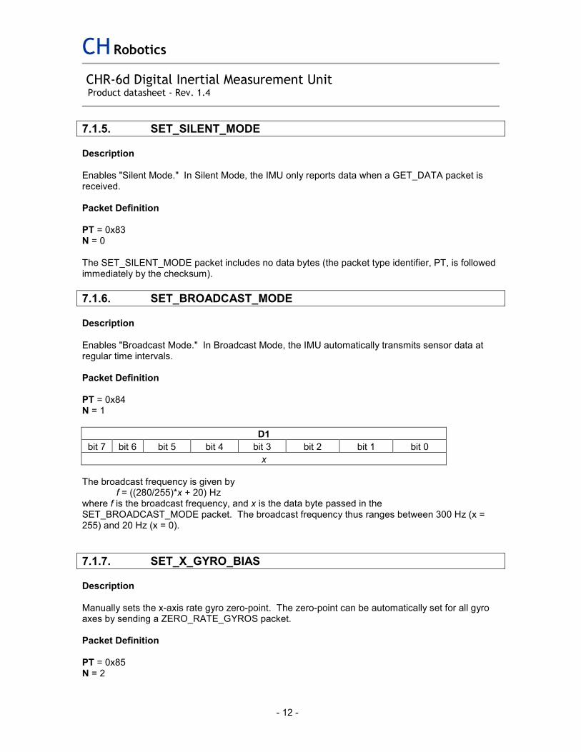
7.1.6. SET_BROADCAST_MODE
Description Enables "Broadcast Mode." In Broadcast Mode, the IMU automatically transmits sensor data at regular time intervals. Packet Definition PT = 0x84 N = 1
D1
bit 7 bit 6 bit 5 bit 4 bit 3 bit 2 bit 1 bit 0
x
The broadcast frequency is given by f = ((280/255)*x + 20) Hz where f is the broadcast frequency, and x is the data byte passed in the SET_BROADCAST_MODE packet. The broadcast frequency thus ranges between 300 Hz (x = 255) and 20 Hz (x = 0).
7.1.7. SET_X_GYRO_BIAS
Description Manually sets the x-axis rate gyro zero-point. The zero-point can be automatically set for all gyro axes by sending a ZERO_RATE_GYROS packet. Packet Definition PT = 0x85 N = 2

CH Robotics
CHR-6d Digital Inertial Measurement Unit Product datasheet - Rev. 1.4
- 13 -
D1 D2
bit 7 bit 6 bit 5 bit 4 bit 3 bit 2 bit 1 bit 0 bit 7 bit 6 bit 5 bit 4 bit 3 bit 2 bit 1 bit 0
Gyro zero-point = 16-bit unsigned value
7.1.8. SET_Y_GYRO_BIAS
Description Manually sets the y-axis rate gyro zero-point. The zero-point can be automatically set for all gyro axes by sending a ZERO_RATE_GYROS packet. Packet Definition PT = 0x86 N = 2
D1 D2
bit 7 bit 6 bit 5 bit 4 bit 3 bit 2 bit 1 bit 0 bit 7 bit 6 bit 5 bit 4 bit 3 bit 2 bit 1 bit 0
Gyro zero-point = 16-bit unsigned value
7.1.9. SET_Z_GYRO_BIAS
Description Manually sets the z-axis rate gyro zero-point. The zero-point can be automatically set for all gyro axes by sending a ZERO_RATE_GYROS packet. Packet Definition PT = 0x87 N = 2
D1 D2
bit 7 bit 6 bit 5 bit 4 bit 3 bit 2 bit 1 bit 0 bit 7 bit 6 bit 5 bit 4 bit 3 bit 2 bit 1 bit 0
Gyro zero-point = 16-bit unsigned value
7.1.10. SET_X_ACCEL_BIAS
Description Manually sets the x-axis accelerometer zero point. Packet Definition

CH Robotics
CHR-6d Digital Inertial Measurement Unit Product datasheet - Rev. 1.4
- 14 -
PT = 0x88 N = 2
D1 D2
bit 7 bit 6 bit 5 bit 4 bit 3 bit 2 bit 1 bit 0 bit 7 bit 6 bit 5 bit 4 bit 3 bit 2 bit 1 bit 0
Accelerometer zero-point = 16-bit unsigned value
7.1.11. SET_Y_ACCEL_BIAS
Description Manually sets the y-axis accelerometer zero point. Packet Definition PT = 0x89 N = 2
D1 D2
bit 7 bit 6 bit 5 bit 4 bit 3 bit 2 bit 1 bit 0 bit 7 bit 6 bit 5 bit 4 bit 3 bit 2 bit 1 bit 0
Accelerometer zero-point = 16-bit unsigned value
7.1.12. SET_Z_ACCEL_BIAS
Description Manually sets the z-axis accelerometer zero point. Packet Definition PT = 0x8A N = 2
D1 D2
bit 7 bit 6 bit 5 bit 4 bit 3 bit 2 bit 1 bit 0 bit 7 bit 6 bit 5 bit 4 bit 3 bit 2 bit 1 bit 0
Accelerometer zero-point = 16-bit unsigned value
7.1.13. ZERO_RATE_GYROS
Description Starts internal self-calibration of all three rate gyro axes. Packet Definition

CH Robotics
CHR-6d Digital Inertial Measurement Unit Product datasheet - Rev. 1.4
- 15 -
PT = 0x8B N = 0 There are no data bytes associated with the ZERO_RATE_GYROS packet. The checksum immediately follows the packet type identifier (PT).
7.1.14. SELF_TEST
Description Instructs the IMU to perform a self-test of all sensor channels. The self-test sequence takes approximately 570 milliseconds to complete. During this time, the IMU should be kept stationary. A STATUS_REPORT packet is transmitted after the self-test is complete. Packet Definition PT = 0x8C N = 0 There are no data bytes associated with the SELF_TEST packet. The checksum immediately follows the packet type identifier (PT).
7.1.15. SET_PROCESS_WEIGHT
Description Sets the process variance used by the onboard EKF for pitch and roll angle estimation. The process variance can vary between values of 0 and 5. The value used by the EKF is specified by variance = weight/13107.2 where variance is the process variance and weight is the 16-bit unsigned value given in the data packet. Packet Definition PT = 0x8D N = 2
D1 D2
bit 7 bit 6 bit 5 bit 4 bit 3 bit 2 bit 1 bit 0 bit 7 bit 6 bit 5 bit 4 bit 3 bit 2 bit 1 bit 0
Process Weight = 16-bit unsigned value
7.1.16. WRITE_TO_FLASH
Description

CH Robotics
CHR-6d Digital Inertial Measurement Unit Product datasheet - Rev. 1.4
- 16 -
Writes IMU configuration to on-board flash, so that the configuration persists when the power is cycled. Packet Definition PT = 0xA0 N = 0 There are no data bytes associated with the WRITE_TO_FLASH packet. The checksum immediately follows the packet type identifier (PT).
7.1.17. GET_DATA
Description In Silent Mode, the IMU waits to receive a GET_DATA packet before transmitting sensor data. The most recent data from all active sensor channels is transmitted in response to a GET_DATA packet. In Broadcast Mode, a GET_DATA packet is ignored. Packet Definition PT = 0x01 N = 0 There are no data bytes associated with the GET_DATA packet. The checksum immediately follows the packet type identifier (PT).
7.1.18. GET_GYRO_BIAS
Description Returns the bias values for all three rate gyros in a GYRO_BIAS_REPORT packet. Packet Definition PT = 0x02 N = 0 There are no data bytes associated with the GET_GYRO_BIAS packet. The checksum immediately follows the packet type identifier (PT).
7.1.19. GET_ACCEL_BIAS
Description Return the bias values for all three accel axes in a ACCEL_BIAS_REPORT packet. Packet Definition

CH Robotics
CHR-6d Digital Inertial Measurement Unit Product datasheet - Rev. 1.4
- 17 -
PT = 0x03 N = 0 There are no data bytes associated with the GET_ACCEL_BIAS packet. The checksum immediately follows the packet type identifier (PT).
7.1.20. GET_FIR_CONFIG
Description Returns the FIR corner frequency configuration for all six sensor channels in a FIR_CONFIG_REPORT packet. Packet Definition PT = 0x04 N = 0 There are no data bytes associated with the GET_FIR_CONFIG packet. The checksum immediately follows the packet type identifier (PT).
7.1.21. GET_FIR_TAP_CONFIG
Description Reports the FIR tap count for all sensor channels in a FIR_TAP_CONFIG_REPORT packet. Packet Definition PT = 0x05 N = 0 There are no data bytes associated with the GET_FIR_TAP_CONFIG packet. The checksum immediately follows the packet type identifier (PT).
7.1.22. GET_ACTIVE_CHANNELS
Description Reports which channels are "active." Active channels are sensor channels that are measured and transmitted in response to a GET_DATA packet, or periodically in Broadcast Mode. Active channels are reported in an ACTIVE_CHANNEL_REPORT packet. Packet Definition PT = 0x06 N = 0

CH Robotics
CHR-6d Digital Inertial Measurement Unit Product datasheet - Rev. 1.4
- 18 -
There are no data bytes associated with the GET_ACTIVE_CHANNELS packet. The checksum immediately follows the packet type identifier (PT).
7.1.23. GET_BROADCAST_MODE
Description Causes the IMU to send a BROADCAST_MODE_REPORT packet, which specifies whether the IMU is in Broadcast Mode or Silent Mode. Packet Definition PT = 0x07 N = 0 There are no data bytes associated with the GET_BROADCAST_MODE packet. The checksum immediately follows the packet type identifier (PT).
7.1.24. GET_PROCESS_WEIGHT
Description Causes the IMU to send a PROCESS_WEIGHT_REPORT packet. Packet Definition PT = 0x08 N = 0 There are no data bytes associated with the GET_PROCESS_WEIGHT packet. The checksum immediately follows the packet type identifier (PT).
7.2. CHR-6d TX Packets
TX Packets are packets that can be transmitted by the IMU. The structure of transmitted packets is exactly the same as the structure of RX packets. TX Packet Structure
Function 's' 'n' 'p' PT N d1 4 dN CHK
Byte 1 2 3 4 5 6 K N+5 N+6 N+7
TX Packet Description 1 - 3 Each received packet must begin with the three-byte (character) sequence

CH Robotics
CHR-6d Digital Inertial Measurement Unit Product datasheet - Rev. 1.4
- 19 -
"snp" to signal the beginning of a new packet.
4 PT specifies the packet type.
5 N specifies the number of data bytes to expect.
6 - (N+5) d1 through dN contain the N data bytes in the packet.
(N+6) - (N+7) CHK is a two-byte checksum.
The total size of a packet with N data bytes is (N + 7) bytes.
7.2.1. CHR-6d TX Packet Overview
Packet Name PT Description
COMMAND_COMPLETE 0xB0 Transmitted by the IMU upon successful completion of a command that does not require data to be returned.
COMMAND_FAILED 0xB1 Transmitted by the IMU when a command received over the UART could not be executed.
BAD_CHECKSUM 0xB2 Transmitted by the IMU when a received packet checksum does not match the sum of the other bytes in the packet.
BAD_DATA_LENGTH 0xB3 Transmitted by the IMU when a received packet contained more or less data than expected for a given packet type.
UNRECOGNIZED_PACKET 0xB4 Transmitted if the IMU receives an unrecognized packet.
BUFFER_OVERFLOW 0xB5 Transmitted by the IMU when the internal receive buffer overflows before a full packet is received.
STATUS_REPORT 0xB6 Transmitted at the end of a self-test procedure, triggered by a SELF_TEST command.
SENSOR_DATA 0xB7 Sent in response to a GET_DATA packet, or sent automatically in Broadcast Mode.
GYRO_BIAS_REPORT 0xB8 Sent in response to the GET_GYRO_BIAS command.
ACCEL_BIAS_REPORT 0xB9 Sent in response to the GET_ACCEL_BIAS command.
FIR_CONFIG_REPORT 0xBA Sent in response to the GET_FIR_CONFIG command.
FIR_TAP_CONFIG_REPORT 0xBB Sent in response to the GET_FIR_TAP_CONFIG command.
ACTIVE_CHANNEL_REPORT 0xBC Sent in response to a GET_ACTIVE_CHANNELS command.
BROADCAST_MODE_REPORT 0XBD Sent in response to a GET_BROADCAST_MODE command.
PROCESS_WEIGHT_REPORT 0xBE Sent in response to a GET_PROCESS_WEIGHT packet
7.2.2. COMMAND_COMPLETE
Description

CH Robotics
CHR-6d Digital IMU datasheet
- 20 -
Transmitted by the IMU upon successful completion of a command that does not require data to be returned. Packet Definition PT = 0xB0 N = 1
D1
bit 7 bit 6 bit 5 bit 4 bit 3 bit 2 bit 1 bit 0
Packet Type (TP) identifier for executed command
7.2.3. COMMAND_FAILED
Description Transmitted by the IMU when a command received over the UART could not be executed. Packet Definition PT = 0xB1 N = 1
D1
bit 7 bit 6 bit 5 bit 4 bit 3 bit 2 bit 1 bit 0
Packet Type (TP) identifier for command that could not be executed
7.2.4. BAD_CHECKSUM
Description Transmitted by the IMU when a received packet checksum does not match the sum of the other bytes in the packet. Packet Definition PT = 0xB2 N = 0
7.2.5. BAD_DATA_LENGTH
Description Transmitted by the IMU when a received packet contained more or less data than expected for a given packet type. Packet Definition PT = 0xB3 N = 1
D1
bit 7 bit 6 bit 5 bit 4 bit 3 bit 2 bit 1 bit 0
Packet Type (TP) identifier of the received packet

CH Robotics
CHR-6d Digital IMU datasheet
- 21 -
7.2.6. UNRECOGNIZED_PACKET
Description Transmitted if the IMU receives an unrecognized packet Packet Definition PT = 0xB4 N = 1
D1
bit 7 bit 6 bit 5 bit 4 bit 3 bit 2 bit 1 bit 0
Packet Type (TP) identifier of unrecognized command
7.2.7. BUFFER_OVERFLOW
Description Transmitted by the IMU when the internal receive buffer overflows before a full packet is received. Packet Definition PT = 0xB5 N = 0
7.2.8. STATUS_REPORT
Description Transmitted at the end of a self-test procedure, triggered by a SELF_TEST command. Packet Definition PT = 0xB6 N = 1
D1
bit 7 bit 6 bit 5 bit 4 bit 3 bit 2 bit 1 bit 0
NA NA gyro_z error
gyro_y error
gyro_x error
accel_z error
accel_y error
accel_x error
If the self-test failed for any of the channels, then the corresponding bit will be set (i.e. if the z-axis gyro fails the self-test, then bit 5 will be set, etc.)
7.2.9. SENSOR_DATA
Description Sent in response to a GET_DATA packet, or sent automatically in Broadcast Mode. Only active channels are included in the packet. Packet Definition PT = 0xB7 N = 1 + 2*(# of active channels)

CH Robotics
CHR-6d Digital IMU datasheet
- 22 -
The first byte following the PT byte indicates which channels are active. The actual sensor data is contained in the remaining data bytes. If all channels are active, then data is given in the following order: { pitch, roll, gyro_z, gyro_y, gyro_x, accel_z, accel_y, accel_x }, where D1 and D2 correspond to pitch, D3 and D4 to roll, etc. Data is returned as 16-bit two's-complement integers. When one or more channel is inactive, then the data is returned in the same order, but skipping the inactive channels. For example, if pitch, roll, gyro_z, gyro_x, and accel_y are disabled, then the data is given in the following order: { gyro_y, accel_z, accel_x }.
D1 D2 D3 D4 D5 K
bit 7 bit 6 bit 5 bit 4 bit 3 bit 2 bit 1 bit 0
pitch roll gz gy gx az ay ax first active channel
second active K
pitch = 1 if the pitch angle estimate is active, 0 otherwise roll = 1 if the roll angle estimate is active, 0 otherwise gz = 1 if the z-axis gyro is active, 0 otherwise gy = 1 if the y-axis gyro is active, 0 otherwise gx = 1 if the x-axis gyro is active, 0 otherwise az = 1 if the z-axis accelerometer is active, 0 otherwise ay = 1 if the y-axis accelerometer is active, 0 otherwise ax = 1 if the x-axis accelerometer is active, 0 otherwise
7.2.10. GYRO_BIAS_REPORT
Description Sent in response to the GET_GYRO_BIAS command Packet Definition PT = 0xB8 N = 6
D1 D2 D3 D4 D5 D6
gyro_z bias gyro_y bias gyro_x bias
7.2.11. ACCEL_BIAS_REPORT
Description Sent in response to the GET_ACCEL_BIAS command Packet Definition PT = 0xB9 N = 6
D1 D2 D3 D4 D5 D6
accel_z bias accel_y bias accel_x bias

CH Robotics
CHR-6d Digital IMU datasheet
- 23 -
7.2.12. FIR_CONFIG_REPORT
Description Sent in response to the GET_FIR_CONFIG command Packet Definition PT = 0xBA N = 3
D1 D2 D3
7 6 5 4 3 2 1 0 7 6 5 4 3 2 1 0 7 6 5 4 3 2 1 0
gyro_z gyro_y gyro_x acc_z acc_y acc_x
The corner frequency of the FIR filter is given by 10*(x-1), where x is a 4-bit unsigned integer. If acc_x = 0b0011 = 3, then the corner of the FIR filter on the accelerometer x-axis is 20 Hz. If x is equal to 0 or 1, then the FIR filter is disabled on that channel.
7.2.13. FIR_TAP_CONFIG_REPORT
Description Sent in response to the GET_FIR_TAP_CONFIG command. Packet Definition PT = 0xBB N = 2
D1 D2
bit 7 bit 6 bit 5 bit 4 bit 3 bit 2 bit 1 bit 0 bit 7 bit 6 bit 5 bit 4 bit 3 bit 2 bit 1 bit 0
NA NA gyro_z gyro_y gyro_x accel_z accel_y accel_x
For each channel, the number of taps in the FIR filter is specified by a 2-bit value, where 00 = 8 taps 01 = 16 taps 10 = 32 taps 11 = 64 taps
7.2.14. ACTIVE_CHANNEL_REPORT
Description Sent in response to a GET_ACTIVE_CHANNELS command Packet Definition PT = 0xBC N = 1
D1
bit 7 bit 6 bit 5 bit 4 bit 3 bit 2 bit 1 bit 0
Pitch Roll gyro_z gyro_y gyro_x accel_z accel_y accel_x

CH Robotics
CHR-6d Digital IMU datasheet
- 24 -
A set bit indicates that the specified channel is active.
7.2.15. BROADCAST_MODE_REPORT
Description Sent in response to a GET_BROADCAST_MODE packet. Specifies whether the IMU is in Broadcast Mode or Silent Mode. Also specifies the broadcast frequency if the IMU is in Broadcast Mode. Packet Definition PT = 0xBD N = 2
D1 D2
bit 7 bit 6 bit 5 bit 4 bit 3 bit 2 bit 1 bit 0 bit 7 bit 6 bit 5 bit 4 bit 3 bit 2 bit 1 bit 0
x NA NA NA NA NA NA NA mode
The broadcast frequency is given by f = ((280/255)*x + 20) Hz where f is the broadcast frequency, and x is the byte stored in D1. The broadcast frequency thus ranges between 300 Hz (when x = 255) and 20 Hz (when x = 0). If mode = 1, then the IMU is in Broadcast Mode. If mode = 0, then the IMU is in Silent Mode.
7.2.16. PROCESS_WEIGHT_REPORT
Description Sent in response to a GET_PROCESS_WEIGHT packet Packet Definition PT = 0xBE N = 2
D1 D2
bit 7 bit 6 bit 5 bit 4 bit 3 bit 2 bit 1 bit 0 bit 7 bit 6 bit 5 bit 4 bit 3 bit 2 bit 1 bit 0
Process Weight = 16-bit unsigned integer
The actual process variance used by the EKF is given by variance = weight / 13107.2

CH Robotics
CHR-6d Digital IMU datasheet
- 25 -
This document is provided as reference only; "typical" device specifications must be evaluated by the end-user. CH Robotics reserves the right to modify this document and the products it describes without notice. CH Robotics products are not intended for use in weapons systems, aircraft, life-saving or life-sustaining systems, automobiles, or any other application where failure could result in injury, death, property damage, or environmental damage.


![[Skolkovo Robotics 2015 Day 1] Зигель Х. Communicating Robotics | Siegel H. Communicating Robotics](https://static.fdocuments.us/doc/165x107/55a657b21a28ab56308b475a/skolkovo-robotics-2015-day-1-communicating-robotics-siegel-h-communicating-robotics.jpg)


