Ch-9 Shaper, Planner, Slotter
29
Shaper, Planner, Slotter By S K Mondal
-
Upload
prateek-bayal -
Category
Documents
-
view
197 -
download
5
description
shaper
Transcript of Ch-9 Shaper, Planner, Slotter
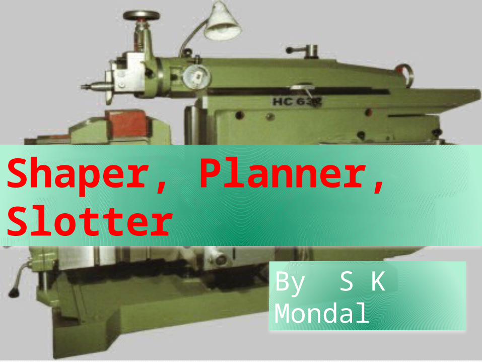
Shaper, Planner, Slotter
By S K Mondal

Shaper
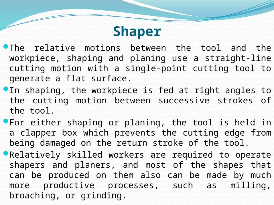
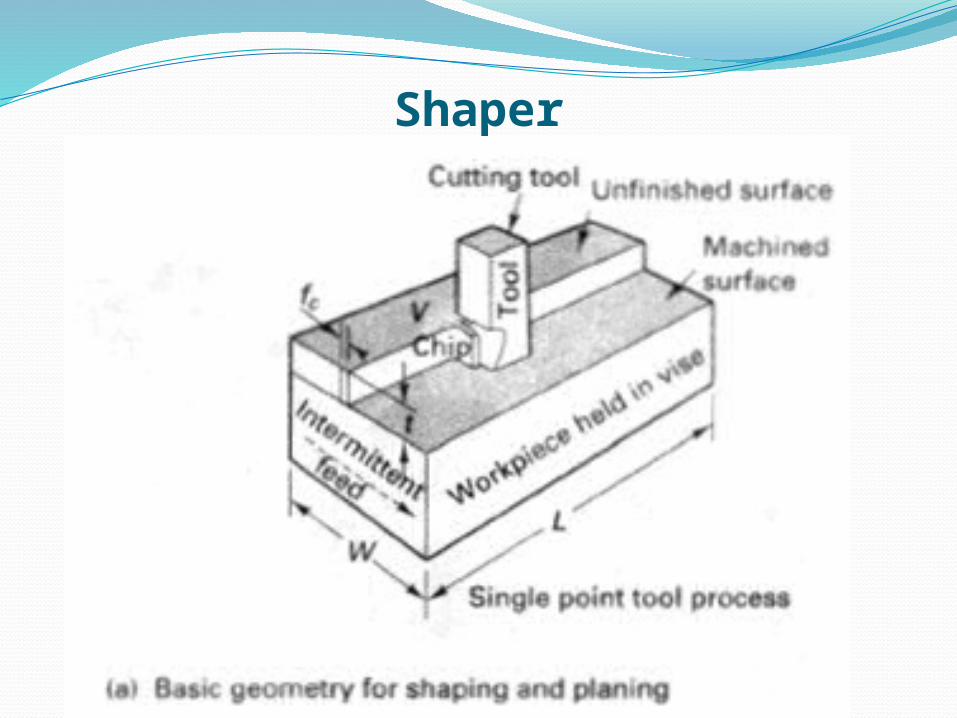
ShaperThe relative motions between the tool and the
workpiece, shaping and planing use a straight-line cutting motion with a single-point cutting tool to generate a flat surface.
In shaping, the workpiece is fed at right angles to the cutting motion between successive strokes of the tool.
For either shaping or planing, the tool is held in a clapper box which prevents the cutting edge from being damaged on the return stroke of the tool.
Relatively skilled workers are required to operate shapers and planers, and most of the shapes that can be produced on them also can be made by much more productive processes, such as milling, broaching, or grinding.
Shaper

Video
Quick return motion Mechanism
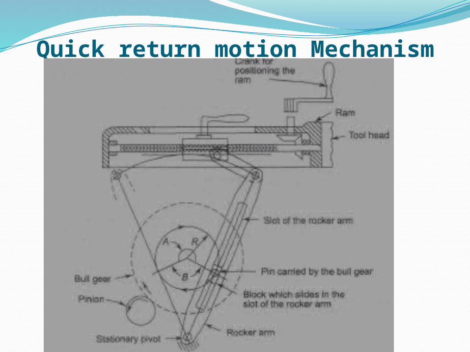
Quick return motion MechanismIn shaping, the cutting tool is held in the tool
post located in the ram, which reciprocates over the work with a forward stroke, cutting at velocity V and a quick return stroke at velocity VR.
The rpm rate of the drive crank (Ns) drives the ram and determines the velocity of the operation.
The stroke ratio,
0360s
cutting strokeangleR
Ram DriveThe mechanical ram drive is a slotted arm
quick return motion mechanism,
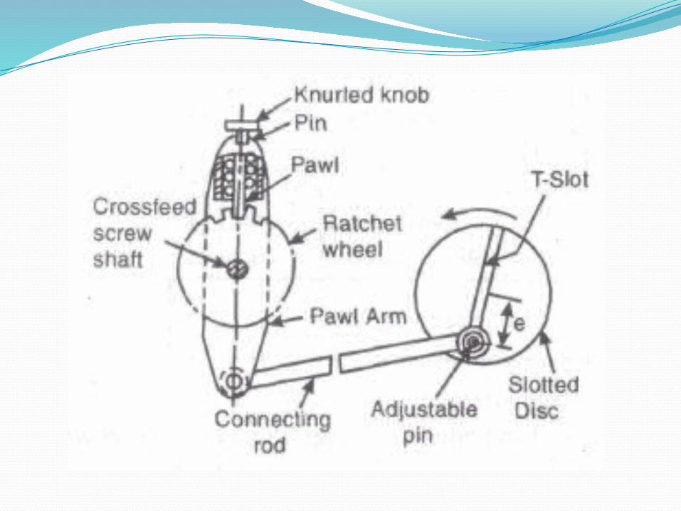
Feed MechanismTable feed is intermittent and is
accomplished on the return (non cutting)
stroke when the tool has cleared the
workpiece.
The cross feed is given to the table with the
help of a cross feed screw which is actuated
by a pawl which engages a notched wheel
(ratchet) keyed to the screw.
Classification of Shaper MachineShapers, as machine tools usually are classified according to their general design features as follows,1. Horizontal
a. Push-cut b. Pull-cut or draw cut shaper2. Vertical
a. Regular or slotters b. Keyseaters3. Special purpose
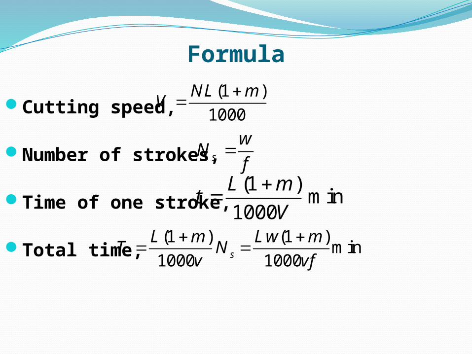
Formula
Cutting speed,
Number of strokes,
Time of one stroke,
Total time,
(1 )1000
NL mV
s
wN
f
(1 )
min1000L m
tV
(1 ) (1 )min
1000 1000s
L m Lw mT N
v vf
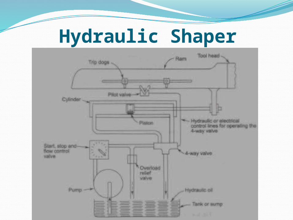
Hydraulic Shaper
Advantages of hydraulic shaping1. Cutting speed remains constant throughout most of the cutting
stroke, unlike the crank shaper where the speed changes continuously.
2. Since the power available remains constant throughout, it is possible to utilise the full capacity of the cutting tool during the cutting stroke.
3. The ram reverses quickly without any shock due the hydraulic cylinder utilised. The inertia of the moving parts is relatively small.
4. The range and number of cutting strokes possible are relatively large in hydraulic shaper.
5. More strokes per minute can be achieved by consuming less time for reversal and return strokes.
PlanerPlaning can be used to produce horizontal,
vertical, or inclined flat surfaces on workpieces that are too large to be accommodated on shapers.
Planing is much less efficient than other basic machining processes, such as milling, that will produce such surfaces.
Planing and planers have largely been replaced by planer milling machines or machines that can do both milling and planing.

Video Planer
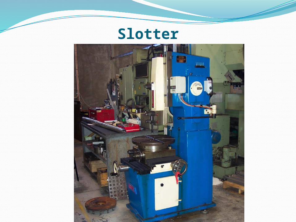
SlotterSlotting machine is basically a vertical axis
shaper. Thus the workpieces, which cannot be conveniently held in shaper, can be machined in a slotter.
Generally, keyways, splines, serrations, rectangular grooves and similar shapes are machined in a slotting machine.
The stroke of the ram is smaller in slotting machines than in shapers to account for the type of the work that is handled in them.
Slotter

Video Slotter
SlotterThe types of tools used in a slotter are very
similar to those in a shaper, except that the cutting actually takes place in the direction of cutting.
However, in view of the type of surfaces that are possible in the case of slotter, a large variety of boring bars or single-point tools with long shanks are used.

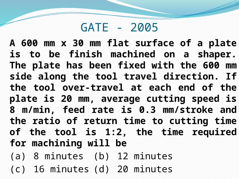
GATE - 2005A 600 mm x 30 mm flat surface of a plate is to be finish machined on a shaper. The plate has been fixed with the 600 mm side along the tool travel direction. If the tool over-travel at each end of the plate is 20 mm, average cutting speed is 8 m/min, feed rate is 0.3 mm/stroke and the ratio of return time to cutting time of the tool is 1:2, the time required for machining will be(a) 8 minutes (b) 12 minutes(c) 16 minutes (d) 20 minutes
IES - 2004Consider the following alignment tests on machine tools1. Straightness 2. Flatness3. Run out 4. ParallelismWhich of the above alignment tests on machine tools are common to both lathe and shaper?(a) 1 and 2 (b) 2 and 3 (c) 3 and 4 (d) 1 and 4
IES - 2001In a shaper machine, the mechanism for tool feed is(a) Geneva mechanism(b) Whitworth mechanism(c) Ratchet and Pawl mechanism(d) Ward- Leonard system

IES - 1995In a mechanical shaper, the length of stroke is increased by(a) Increasing the centre distance of bull gear and crank pin(b) Decreasing the centre distance of bull gear and crank pin(c) Increasing the length of the ram(d) Decreasing the length of the slot in the slotted lever
ISRO-2010The cutting speed of the tool in a mechanical shaper is
(a) Maximum at the beginning of the cutting stroke
(b) Maximum at the end of the cutting stroke(c) Maximum at the middle of the cutting
stroke(d) Minimum at the middle of the cutting
stroke

IAS - 1994Stroke of a shaping machine is 250 mm. It makes 30 double strokes per minute. Overall average speed of operation is(a) 3.75 m/min (b) 5.0 m/min(c) 7.5 m/min (d) 15 m/min


Q. No Option1 C2 A3 C4 B5 B6 C
Ch-5: Shaping and Planning