CH 9 consolidation - ced.ceng.tu.edu.iq
43
Tikrit University College of Engineering Civil engineering Department Soil Mechanics 3 rd Class Lecture notes Up Copyrights 2016 CONSOILDATION
Transcript of CH 9 consolidation - ced.ceng.tu.edu.iq

Tikrit University
College of Engineering
Civil engineering Department
Soil Mechanics
3rd ClassLecture notes
Up Copyrights 2016
CONSOILDATION

Consolidation
College of Eng. Civil Eng. Dept Soil Mechanics Dr. Ahmed Al-Obaidi
Stresses at a point in a soil mass are divided into two main types:
I- Geostatic Stresses ------ Due to the self weight of the soil mass.
II- Excess Stresses ------ From structures
I. Geostatic stresses
II. I.A. Vertical Stress
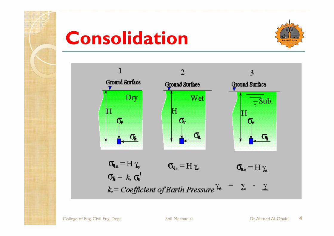
Vertical geostatic stresses increase with depth, There are three 3 types of geostatic stresses
2

Consolidation
College of Eng. Civil Eng. Dept Soil Mechanics Dr. Ahmed Al-Obaidi
1-a Total Stress, stotal
1-b. Effective Stress, seff, or s'
1-c Pore Water Pressure, u
Total Stress = Effective stress + Pore Water Pressure
stotal = seff + u
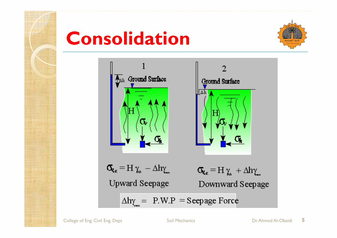
When the Seepage Force = H gsub -- Effective Stress seff = 0 this case is referred as
Boiling or Quick Condition
3
Consolidation
College of Eng. Civil Eng. Dept Soil Mechanics Dr. Ahmed Al-Obaidi 4
Consolidation
College of Eng. Civil Eng. Dept Soil Mechanics Dr. Ahmed Al-Obaidi 5
Consolidation
College of Eng. Civil Eng. Dept Soil Mechanics Dr. Ahmed Al-Obaidi
I.B. Horizontal Stress or Lateral Stress
sh = ko s'v
ko = Lateral Earth Pressure Coefficient
sh is always associated with the vertical effective stress, s'v.
never use total vertical stress to determine sh.
II. Stress Distribution in Soil Mass:
When applying a load on a half space medium the excess stresses in the soil will decrease with depth.
6

Consolidation
College of Eng. Civil Eng. Dept Soil Mechanics Dr. Ahmed Al-Obaidi
Like in the geostatic stresses, there are vertical and lateral excess stresses.
1. For Point Load
The excess vertical stress is according to Boussinesq(1883):
7
- Ip = Influence factor for the point load
- Knowing r/z ----- I1 can be obtained from tables
According to Westergaard (1938)

Consolidation
College of Eng. Civil Eng. Dept Soil Mechanics Dr. Ahmed Al-Obaidi 8
where h = s (1-2m / 2-2m) m = Poisson's Ratio
2. For Line Load
Using q/unit length on the surface of a semi infinite soil mass, the vertical stress is:

Consolidation
College of Eng. Civil Eng. Dept Soil Mechanics Dr. Ahmed Al-Obaidi
3. For a Strip Load (Finite Width and Infinite Length):
The excess vertical stress due to load/unit area, q, is:
9
Where Il = Influence factor for a line load
3. For a Circular Loaded Area:
The excess vertical stress due to q is:
Consolidation
College of Eng. Civil Eng. Dept Soil Mechanics Dr. Ahmed Al-Obaidi
Compression and Consolidation of Soils When a soil layer is subjected to vertical stress, volume change can take place through rearrangement of soil grains, and some amount of grain fracture may also take place. The volume of soil grains remains constant, so change in total volume is due to change in volume of water. In saturated soils, this can happen only if water is pushed out of the voids. The movement of water takes time and is controlled by the permeability of the soil and the locations of free draining boundary surfaces.
10
Consolidation
College of Eng. Civil Eng. Dept Soil Mechanics Dr. Ahmed Al-Obaidi
It is necessary to determine both the magnitude of volume change (or the settlement) and the time required for the volume change to occur. The magnitude of settlement is dependent on the magnitude of applied stress, thickness of the soil layer, and the compressibility of the soil. When soil is loaded undrained, the pore pressure increases. As the excess pore pressure dissipates and water leaves the soil, settlement takes place. This process takes time, and the rate of settlement decreases over time. In coarse soils (sands and gravels), volume change occurs immediately as pore pressures are dissipated rapidly due to high permeability. In fine soils (silts and clays), slow seepage occurs due to low permeability.
11

Consolidation
College of Eng. Civil Eng. Dept Soil Mechanics Dr. Ahmed Al-Obaidi
Components of Total Settlement
The total settlement of a loaded soil has three components: Elastic settlement, primary consolidation, and secondary compression.
Elastic settlement is on account of change in shape at constant volume, i.e. due to vertical compression and lateral expansion. Primary consolidation (or simply consolidation) is on account of flow of water from the voids, and is a function of the permeability and compressibility of soil. Secondary compression is on account of creep-like behaviour.
12
Consolidation
College of Eng. Civil Eng. Dept Soil Mechanics Dr. Ahmed Al-Obaidi
Primary consolidation is the major component and it can be reasonably estimated. A general theory for consolidation, incorporating three-dimensional flow is complicated and only applicable to a very limited range of problems in geotechnical engineering. For the vast majority of practical settlement problems, it is sufficient to consider that both seepage and strain take place in one direction only, as one-dimensional consolidation in the vertical direction.
Compressibility Characteristics
Soils are often subjected to uniform loading over large areas, such as from wide foundations, fills or embankments. Under such conditions, the soil which is remote from the edges of the loaded area undergoes vertical strain, but no horizontal strain. Thus, the settlement occurs only in one-dimension.
13
Consolidation
College of Eng. Civil Eng. Dept Soil Mechanics Dr. Ahmed Al-Obaidi
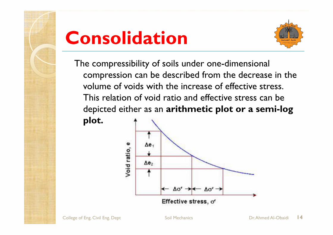
The compressibility of soils under one-dimensional compression can be described from the decrease in the volume of voids with the increase of effective stress. This relation of void ratio and effective stress can be depicted either as an arithmetic plot or a semi-log plot.
14
Consolidation
College of Eng. Civil Eng. Dept Soil Mechanics Dr. Ahmed Al-Obaidi
In the arithmetic plot as shown, as the soil compresses, for the same increase of effective stress Ds', the void ratio reduces by a smaller magnitude, from De1 to De2. This is on account of an increasingly denser packing of the soil particles as the pore water is forced out. In fine soils, a much longer time is required for the pore water to escape, as compared to coarse soils.
It can be said that the compressibility of a soil decreases as the effective stress increases. This can be represented by the slope of the void ratio – effective stress relation, which is called the coefficient of compressibility, av.
15
Consolidation
College of Eng. Civil Eng. Dept Soil Mechanics Dr. Ahmed Al-Obaidi 16
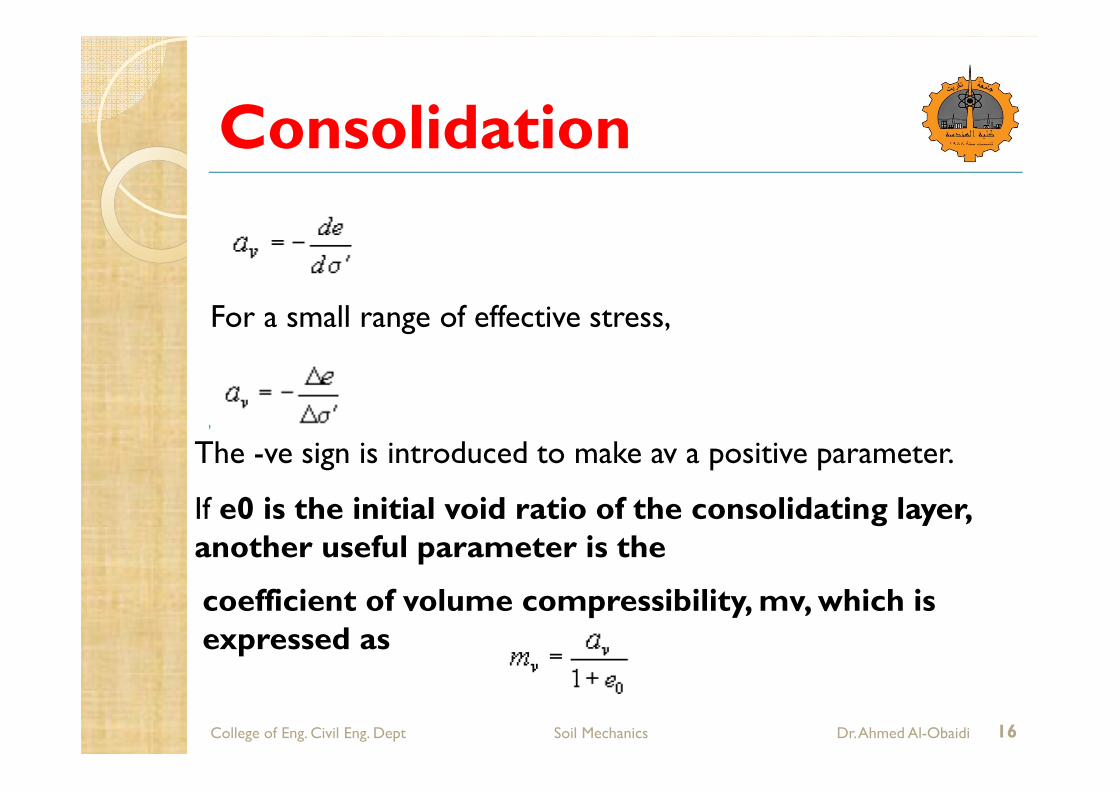
For a small range of effective stress,
The -ve sign is introduced to make av a positive parameter.
If e0 is the initial void ratio of the consolidating layer, another useful parameter is the
coefficient of volume compressibility, mv, which is expressed as
Consolidation
College of Eng. Civil Eng. Dept Soil Mechanics Dr. Ahmed Al-Obaidi 17
It represents the compression of the soil, per unit original thickness, due to a unit increase of pressure.
Normally Consolidated and Over-Consolidated Clays
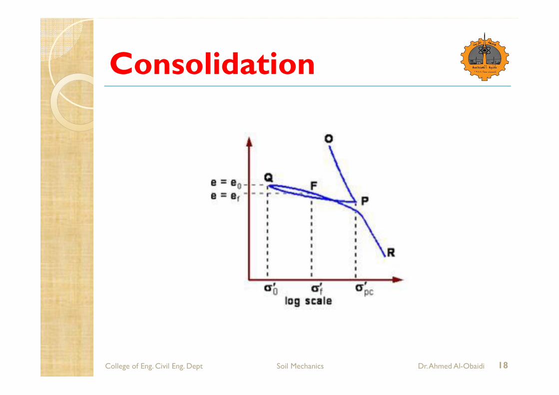
The figure shows the relation of void ratio and effective stress of a clay soil as a semi-log plot.
Consolidation
College of Eng. Civil Eng. Dept Soil Mechanics Dr. Ahmed Al-Obaidi 18
Consolidation
College of Eng. Civil Eng. Dept Soil Mechanics Dr. Ahmed Al-Obaidi 19
OP corresponds to initial loading of the soil. PQ corresponds to unloading of the soil. QFR corresponds to a reloading of the soil. Upon reloading beyond P, the soil continues along the path that it would have followed if loaded from O to R continuously. The preconsolidation stress, s'pc, is defined to be the maximum effective stress experienced by the soil. This stress is identified in comparison with the effective stress in its present state. For soil at state Q or F, this would correspond to the effective stress at point P. If the current effective stress, s', is equal (note that it cannot be greater than) to the preconsolidation stress, then the deposit is said to be normally consolidated (NC). If the current effective stress is less than the preconsolidation stress, then the soil is said to be over-consolidated (OC).
Consolidation
College of Eng. Civil Eng. Dept Soil Mechanics Dr. Ahmed Al-Obaidi 20
It may be seen that for the same increase in effective stress, the change in void ratio is much less for an overconsolidated soil (from e0 to ef), than it would have been for a normally
consolidated soil as in path OP. In unloading, the soil swells but the increase in volume is much less than the initial decrease in volume for the same stress difference. The distance from the normal consolidation line has an important influence on soil behaviour. This is described numerically by the overconsolidation ratio (OCR), which is defined as the ratio of the preconsolidationstress to the current effective stress.

Consolidation
College of Eng. Civil Eng. Dept Soil Mechanics Dr. Ahmed Al-Obaidi 21
Note that when the soil is normally consolidated, OCR = 1 Settlements will generally be much smaller for structures built on overconsolidated soils. Most soils are overconsolidated to some degree. This can be due to shrinking and swelling of the soil on drying and rewetting, changes in ground water levels, and unloading due to erosion of overlying strata. For NC clays, the plot of void ratio versus log of effective stress can be approximated to a straight line, and the slope of this line is indicated by a parameter termed as compression index, Cc.

Consolidation
College of Eng. Civil Eng. Dept Soil Mechanics Dr. Ahmed Al-Obaidi 22
Estimation of Preconsolidation Stress
It is possible to determine the preconsolidation stress that the soil had experienced. The soil sample is to be loaded in the laboratory so as to obtain the void ratio - effective stress relationship. Empirical procedures are used to estimate the preconsolidation stress, the most widely used being Casagrande's construction which is illustrated.

Consolidation
College of Eng. Civil Eng. Dept Soil Mechanics Dr. Ahmed Al-Obaidi 23

Consolidation
College of Eng. Civil Eng. Dept Soil Mechanics Dr. Ahmed Al-Obaidi 24
The steps in the construction are:
• Draw the graph using an appropriate scale.
• Determine the point of maximum curvature A. • At A, draw a tangent AB to the curve. • At A, draw a horizontal line AC. • Draw the extension ED of the straight line portion of the curve. • Where the line ED cuts the bisector AF of angle CAB, that point corresponds to the preconsolidationstress.
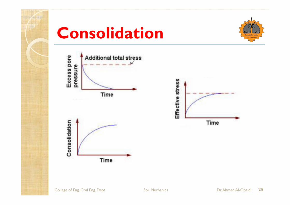
Analysis of Consolidation -Terzaghi'sTheory The total stress increases when additional vertical load is first applied. Instantaneously, the pore water pressure increases by exactly the same amount. Subsequently there will be flow from regions of higher excess pore pressure to regions of lower excess pore pressure causing dissipation. The effective stress will change and the soil will consolidate with time. This is shown schematically.
Consolidation
College of Eng. Civil Eng. Dept Soil Mechanics Dr. Ahmed Al-Obaidi 25

Consolidation
College of Eng. Civil Eng. Dept Soil Mechanics Dr. Ahmed Al-Obaidi 26
On the assumption that the excess pore water drains only along vertical lines, an analytical procedure can be developed for computing the rate of consolidation. Consider a saturated soil element of sides dx, dy and dz.
Consolidation
College of Eng. Civil Eng. Dept Soil Mechanics Dr. Ahmed Al-Obaidi 27
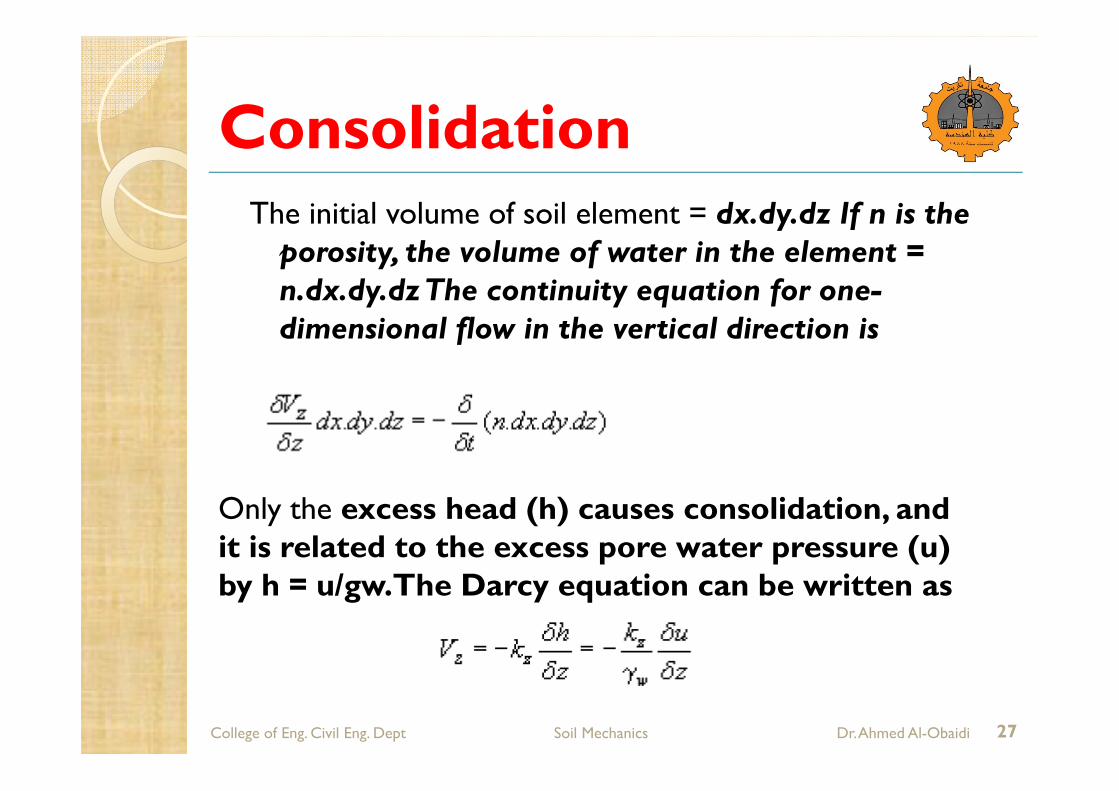
The initial volume of soil element = dx.dy.dz If n is the porosity, the volume of water in the element = n.dx.dy.dz The continuity equation for one-dimensional flow in the vertical direction is
Only the excess head (h) causes consolidation, and it is related to the excess pore water pressure (u) by h = u/gw.The Darcy equation can be written as

Consolidation
College of Eng. Civil Eng. Dept Soil Mechanics Dr. Ahmed Al-Obaidi 28
The Darcy eqn. can be substituted in the continuity eqn., and the porosity n can be expressed in terms of void ratio e, to obtain the flow equation as
The soil element can be represented schematically as

Consolidation
College of Eng. Civil Eng. Dept Soil Mechanics Dr. Ahmed Al-Obaidi 29
If e0 is the initial void ratio of the consolidating layer, the initial volume of solids in the element is (dx dy dz) / (1 + e0), which remains constant. The change in water volume can be represented by small changes De in the current void ratio e. The flow eqn. can then be written as
or

Consolidation
College of Eng. Civil Eng. Dept Soil Mechanics Dr. Ahmed Al-Obaidi 30
This is the hydrodynamic equation of one-dimensional consolidation. If av = coefficient of compressibility, the change in void ratio can be expressed as De = av.(-Ds') = av.(Du) since any increase in effective stress equals the decrease in excess pore water pressure. Thus,
The flow eqn. can then be expressed as

Consolidation
College of Eng. Civil Eng. Dept Soil Mechanics Dr. Ahmed Al-Obaidi 31
or
By introducing a parameter called the coefficient of consolidation,
the flow eqn. then becomes

Consolidation
College of Eng. Civil Eng. Dept Soil Mechanics Dr. Ahmed Al-Obaidi 32
This is Terzaghi's one-dimensional consolidation equation. A solution of this for a set of boundary conditions will describe how the excess pore water pressure u dissipates with time t and location z. When all the u has dissipated completely throughout the depth of the compressible soil layer, consolidation is complete and the transient flow situation ceases to exist.
Solution of Terzaghi'sTheory

Consolidation
College of Eng. Civil Eng. Dept Soil Mechanics Dr. Ahmed Al-Obaidi 33
During the consolidation process, the following are assumed to be constant: 1. The total additional stress on the compressible soil layer is assumed to remain constant. 2. The coefficient of volume compressibility (mV) of the soil is assumed to be constant. 3. The coefficient of permeability (k) for vertical flow is assumed to be constant.
There are three variables in the consolidation equation: 1. the depth of the soil element in the layer (z) 2. the excess pore water pressure (u) 3. the time elapsed since application of the loading (t)
Consolidation
College of Eng. Civil Eng. Dept Soil Mechanics Dr. Ahmed Al-Obaidi 34
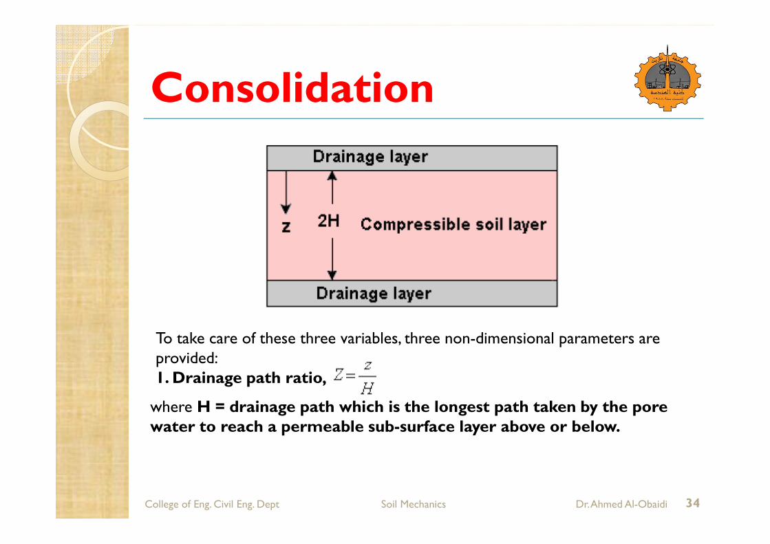
To take care of these three variables, three non-dimensional parameters are provided: 1. Drainage path ratio,
where H = drainage path which is the longest path taken by the pore water to reach a permeable sub-surface layer above or below.
Consolidation
College of Eng. Civil Eng. Dept Soil Mechanics Dr. Ahmed Al-Obaidi 35
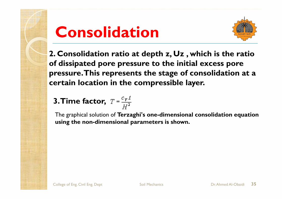
2. Consolidation ratio at depth z, Uz , which is the ratio of dissipated pore pressure to the initial excess pore pressure. This represents the stage of consolidation at a certain location in the compressible layer.
3. Time factor,
The graphical solution of Terzaghi's one-dimensional consolidation equation using the non-dimensional parameters is shown.

Consolidation
College of Eng. Civil Eng. Dept Soil Mechanics Dr. Ahmed Al-Obaidi 36

Consolidation
College of Eng. Civil Eng. Dept Soil Mechanics Dr. Ahmed Al-Obaidi 37
The figure is symmetrical about the horizontal line at
For double drainage conditions, pore water above this location flows upwards whereas water below this location flows downwards. Thus, the horizontal line at Z = 1 is equivalent to an imperious boundary. For single drainage conditions, only either the top half or bottom half of the figure is to be used, and the drainage path is equal to the thickness of the compressible layer. The above graphical solution shows how consolidation proceeds with time at different locations for a particular set of boundary conditions, but it does not describe how much consolidation occurs as a whole in the entire compressible layer.
Consolidation
College of Eng. Civil Eng. Dept Soil Mechanics Dr. Ahmed Al-Obaidi 38
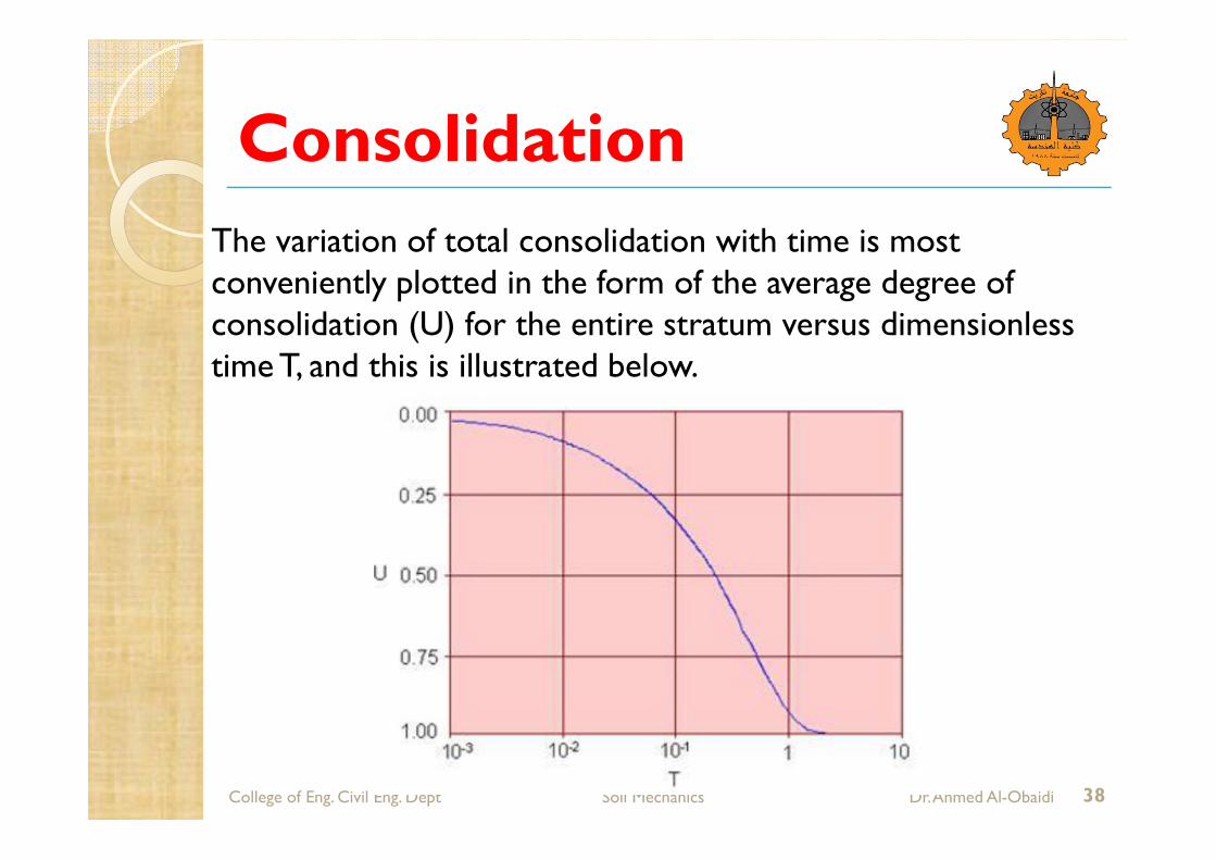
The variation of total consolidation with time is most conveniently plotted in the form of the average degree of consolidation (U) for the entire stratum versus dimensionless time T, and this is illustrated below.
Consolidation
College of Eng. Civil Eng. Dept Soil Mechanics Dr. Ahmed Al-Obaidi 39
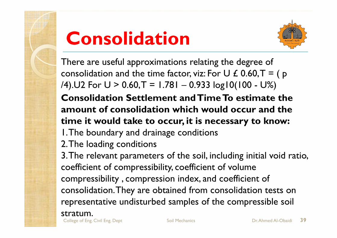
There are useful approximations relating the degree of consolidation and the time factor, viz: For U £ 0.60, T = ( p /4).U2 For U > 0.60, T = 1.781 – 0.933 log10(100 - U%)
Consolidation Settlement and Time To estimate the amount of consolidation which would occur and the time it would take to occur, it is necessary to know: 1. The boundary and drainage conditions 2. The loading conditions 3. The relevant parameters of the soil, including initial void ratio, coefficient of compressibility, coefficient of volume compressibility , compression index, and coefficient of consolidation. They are obtained from consolidation tests on representative undisturbed samples of the compressible soil stratum.
Consolidation
College of Eng. Civil Eng. Dept Soil Mechanics Dr. Ahmed Al-Obaidi 40
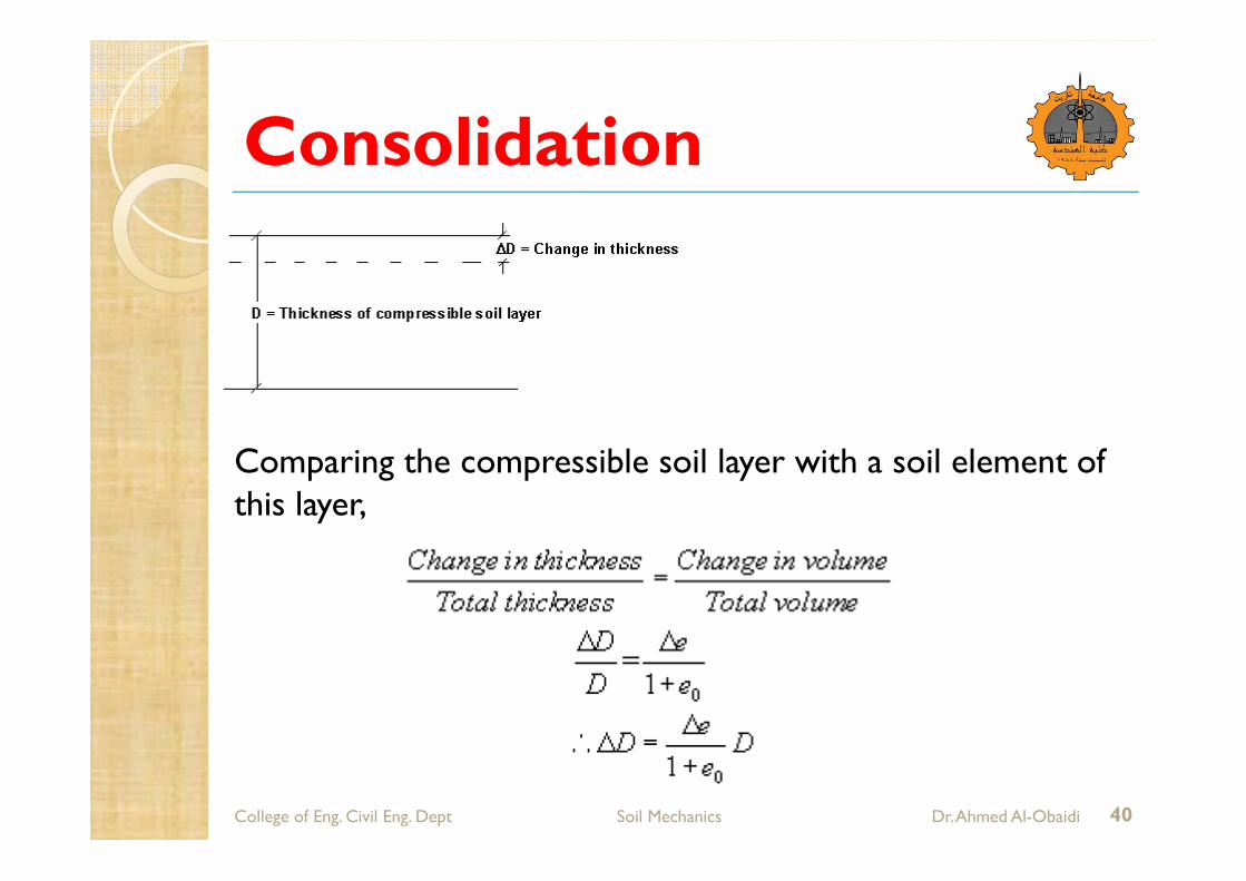
Comparing the compressible soil layer with a soil element of this layer,
Consolidation
College of Eng. Civil Eng. Dept Soil Mechanics Dr. Ahmed Al-Obaidi 41
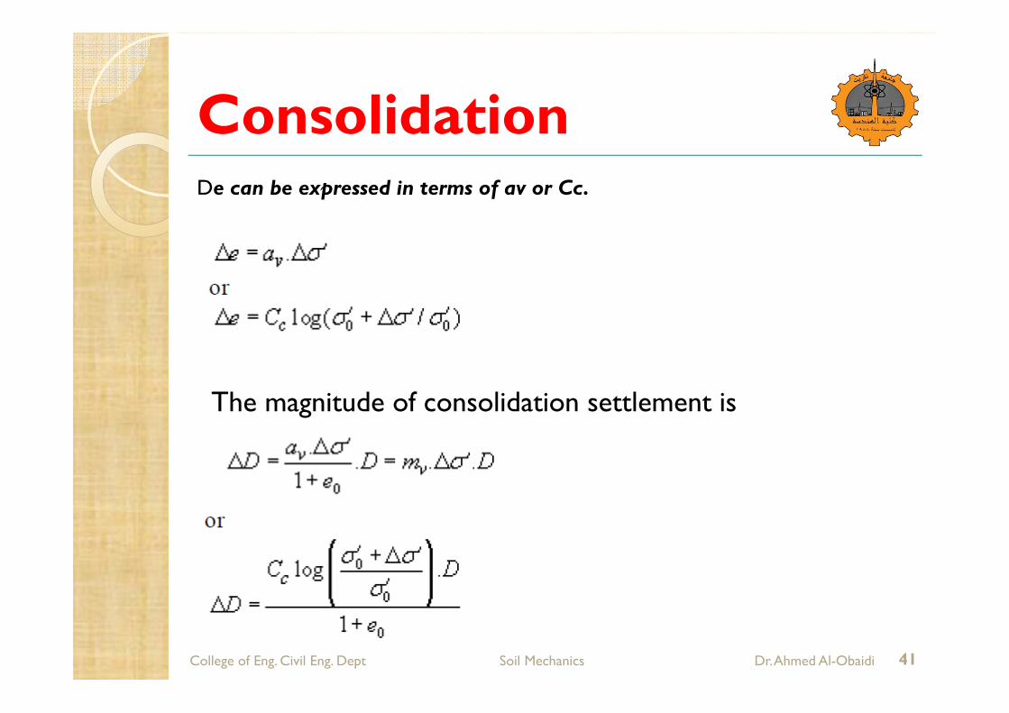
De can be expressed in terms of av or Cc.
The magnitude of consolidation settlement is
Consolidation
College of Eng. Civil Eng. Dept Soil Mechanics Dr. Ahmed Al-Obaidi 42

Consolidation
College of Eng. Civil Eng. Dept Soil Mechanics Dr. Ahmed Al-Obaidi 43
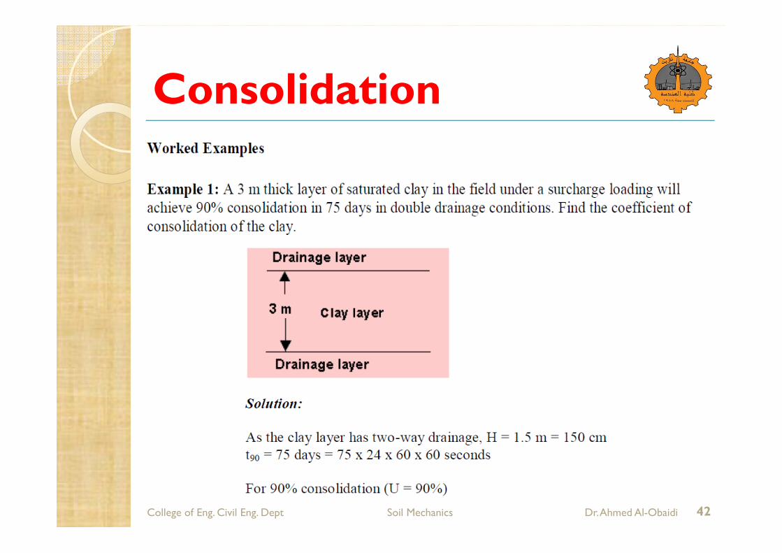
Examples


![Petroleum (Consolidation) Act, 1928. · Petroleum (Consolidation) Act, 1928. [18 & 19 GEO. 5. CH. 32.] SuPPL/E FOR TH E QSER ARRANGEMENT OF SECTIONS. A:D.1928, Licences for Keeping](https://static.fdocuments.us/doc/165x107/5fc0ff26196d6c44326d6f60/petroleum-consolidation-act-1928-petroleum-consolidation-act-1928-18-.jpg)