CH 7 TECHNICAL NOTES
5
80 CHAPTER 7 TECHNICAL NOTES Power factor correction: why? In electrical circuits the current is in phase with the voltage whenever are in presence of resistors, whereas the current is lagging if the load is inductive (motors, transformers with no load conditions), and leading if the load is capacitive (capacitors). φ = 0° φ = 90° rit φ = 90° ant The total absorbed current, for example, by a motor is determined by vector addition of: • I R resistive current; • I L inductive reactive current; φ cosφ = I R I These currents are related to the following powers: • Active power linked to I R ; • Reactive power linked to I L ; The reactive power doesn’t produce mechanical work and it is an additional load for the energy supplier. The parameter that defines the consumption of reactive power is the power factor. We define power factor the ratio between active power and apparent power: φ FP = P A A = P 2 + Q 2 As far as there are not harmonic currents power factor coincides to cosφ of the angle between current and voltage vectors. Cosφ decreases as the reactive absorbed power increases. Low cosφ, has the following disadvantages: • High power losses in the electrical lines. • High voltage drop in the electrical lines. • Over sizing of generators, electric lines and transformers. From this we understand the importance to improve (increase) the power factor. Capacitors need to obtain this result. Power factor correction: how? By installing a capacitor bank it is possible to reduce the reactive power absorbed by the inductive loads in the system and consequently to improve power factor. It is suitable to have cosφ a little in excess of 0.95 to avoid paying the penalties provided for by the law. The choice of the correct power factor correction equipment depends on the type of loads present and by their way of working. The choice is between individual compensation and central compensation. Nel caso di rifasamento distribuito, le unità rifasanti sono disposte nelle immediate vicinanze di ogni singolo carico che si vuole rifasare. Individual compensation: power factor correction is wired at each single load (i.e. motor terminals). Central compensation: there is only one bank of capacitors on the main power distribution switch board or substation. M M M M M M M Individual compensation Central compensation The individual compensation is a simple technical solution: the capacitor and the user equipment follow the same sorts during the daily work, so the regulation of the cosφ becomes systematic and closely linked to the load. Another great advantage of this type of power factor correction is the simple installation with low costs. The daily trend of the loads has a fundamental importance for the choice of most suitable power factor correction. In many systems, not all the loads work in the same time and some of them work only a few hours per day. It is clear that the solution of the individual compensation becomes too expensive for the high number of capacitors that have to be installed. Most of these capacitors will not be used for long period of time. The individual compensation is more effective if the majority of the reactive power is concentrated on a few substatios loads that work long period of time. Central compensation is best suited for systems where the load fluctuates throughout the day. If the absorption of reactive power is very variable, it is advisable the use of automatic regulation in preference to fixed capacitors.
Transcript of CH 7 TECHNICAL NOTES

80
CHAPTER 7
TECHNICAL NOTESPower factor correction whyIn electrical circuits the current is in phase with the voltage whenever are in presence of resistors whereas the current is lagging if the load is inductive (motors transformers with no load conditions) and leading if the load is capacitive (capacitors)
φ = 0deg φ = 90deg rit φ = 90deg ant
The total absorbed current for example by a motor is determined by vector addition of
bull IR resistive currentbull IL inductive reactive current
φ
cosφ = IR
I
These currents are related to the following powersbull Active power linked to IRbull Reactive power linked to IL
The reactive power doesnrsquot produce mechanical work and it is an additional load for the energy supplierThe parameter that defines the consumption of reactive power is the power factorWe define power factor the ratio between active power and apparent power
φ
FP = P
A
A = P2 + Q2
As far as there are not harmonic currents power factor coincides to cosφ of the angle between current and voltage vectorsCosφ decreases as the reactive absorbed power increases
Low cosφ has the following disadvantagesbull High power losses in the electrical linesbull High voltage drop in the electrical linesbull Over sizing of generators electric lines and transformers
From this we understand the importance to improve (increase) the power factorCapacitors need to obtain this result
Power factor correction howBy installing a capacitor bank it is possible to reduce the reactive power absorbed by the inductive loads in the system and consequently to improve power factor It is suitable to have cosφ a little in excess of 095 to avoid paying the penalties provided for by the lawThe choice of the correct power factor correction equipment depends on the type of loads present and by their way of workingThe choice is between individual compensation and central compensationNel caso di rifasamento distribuito le unitagrave rifasanti sono disposte nelle immediate vicinanze di ogni singolo carico che si vuole rifasareIndividual compensation power factor correction is wired at each single load (ie motor terminals)Central compensation there is only one bank of capacitors on the main power distribution switch board or substation
M M M MM M M
Individual compensation Central compensation
The individual compensation is a simple technical solution the capacitor and the user equipment follow the same sorts during the daily work so the regulation of the cosφ becomes systematic and closely linked to the load Another great advantage of this type of power factor correction is the simple installation with low costs The daily trend of the loads has a fundamental importance for the choice of most suitable power factor correction In many systems not all the loads work in the same time and some of them work only a few hours per day It is clear that the solution of the individual compensation becomes too expensive for the high number of capacitors that have to be installed Most of these capacitors will not be used for long period of timeThe individual compensation is more effective if the majority of the reactive power is concentrated on a few substatios loads that work long period of timeCentral compensation is best suited for systems where the load fluctuates throughout the day If the absorption of reactive power is very variable it is advisable the use of automatic regulation in preference to fixed capacitors
81
CHAPTER 7CHAPTER 7
Power factor correction How manyThe choice of capacitor bank to install in a system is closely depended from
bull cosφ2 value that we would obtainbull cosφ1 starting valuebull installed active power
By the following equation
QC = P middot (tanφ1 ndash tanφ2)
φ1φ2
Can be also written QC = k middot P
where the parameter k is easily calculated using Table 1 (in APPENDIX)As example if we have installed a load that absorbs an active power of 300 kW having a power factor 07 and we want to increase it until 097From the table 1 we find k = 0770and therefore
QC = 0770 middot 300 = 231 kvar
whereQC = required capacitors reactive output (kvar)P = active power (kW)QL QLrsquo = inductive reactive output before and after the installation of the capacitor bankA Arsquo= apparent power before and after the power factor correction (kVA)
A typical example of power factor correction sometimes not much considered but surely important concerns the power factor correction of transformers for the distribution of energyIt is essentially a fixed power factor correction that must compensate for the reactive power absorbed by the transformer in its no load condition (this happens often during the night) The calculation of the needed reactive output is very easy and it bases itself on this equation
QC = I0 AN
100
whereI0 = magnetising current of the transformerAN = apparent rated power in kVA of the transformer
If we donrsquot have these parameters it is convenient to use thefollowing table
Power transformer[kVA]
Oil[kvar]
Resin[kvar]
10 1 1520 2 1750 4 275 5 25
100 5 25160 7 4
200 75 5
250 8 75315 10 75400 125 8500 15 10630 175 125800 20 15
1000 25 1751250 30 201600 35 222000 40 252500 50 353150 60 50
Another very important example of power factor correction concerns asynchronous three-phase motors that areindividually correctedThe reactive power likely needed is reported on following table
Motor power Required reactive power [kvar]
HP KW 3000rpm
1500rpm
1000rpm
750 rpm
500rpm
04 055 ndash ndash 05 05 ndash1 073 05 05 06 06 ndash2 147 08 08 1 1 ndash3 221 1 1 12 16 ndash5 368 16 16 2 25 ndash7 515 2 2 25 3 ndash
10 736 3 3 4 4 5
15 11 4 5 5 6 630 221 10 10 10 12 1550 368 15 20 20 25 25
100 736 25 30 30 30 40150 110 30 40 40 50 60200 147 40 50 50 60 70250 184 50 60 60 70 80
Be careful the capacitor output must not be dimensioned too high for individual compensated machines where the capacitor is directly connected with the motor terminals The capacitor placed in parallel may act as a generator for the motor which will cause serious overvoltages (self-excitation phenomena) In case of wound rotor motor the reactive power of the capacitor bank must be increased by 5
82
CHAPTER 7
Power factor correctiontechnical reasonsRecent energy market deregulation along with new potential energy supplier rising had lead to many and different type of invoicing which are not very clear in showing Power Factor up However as energy final price is steady growing to correct power factor is becoming more and more convenient In most of the cases power factor improvement device prime cost is paid back in few monthsTechnical-economical advantages of the installation of acapacitor bank are the following
bull Decrease of the losses in the network and on the transformers caused by the lower absorbed current
bull Decrease of voltage drops on linesbull Optimisation of the system sizing
The current I that flows in the system is calculated by
I = P
3 V cosφ
whereP = Active powerV = Nominal voltage
While cosφ increases with the same absorbed power we can obtain a reduction in the value of the current and as a consequence the losses in the network and on the transformers are reducedTherefore we have an important saving on the size of electrical equipment used on a system The best system sizing has some consequence on the line voltage drop We can easily see that looking at the following formula
∆V = R + X PV
QV
whereP = Active power on the network (kW)Q = Reactive power on the network (kvar)while R is the cable resistance and X its reactance (RltltX)
The capacitor bank installation reduces Q so we have a lower voltage drop If for a wrong calculation of the installed capacitor bank value the reactive part of the above equation becomes negative instead of a reduction of the voltage drop we have an increasing of the voltage at the end of the line (Ferranti Effect) with dangerous consequence for the installed loads
Some examples clarify the concepts set out above
cosφ Power loss1 [kW] Supplied active power2 [kW]
05 32 5006 23 6007 16 7008 13 8009 1 901 0 100
1 In function of cosφ from a copper cable 3 x 25mm2 100m long carrying 40kW at 400Vac2 By a 100kVA transformer in function of cosφ
As we can see as the power factor increases we have fewer losses in the network and more active power from the same KVAThis allows us to optimise on the system sizing
Power factor correctionHarmonics in the networkThe distortions of the voltage and current waveforms are generated by non-linear loads (inverter saturated transformers rectifier etc) and produce the following problems
bull On the AC motors we find mechanical vibration that can reduce expected life The increase of the losses creates overheating with consequent damaging of the insulating materials
bull In transformers they increase the copper and iron losses with possible damaging of the windings The presence of direct voltage or current could cause the saturation of the cores with consequent increasing of the magnetising current
bull The capacitors suffer from the overheating and the increasing of the voltage that reduce their life
The waveform of the current (or voltage) generated by a nonlinear load being periodical could be represented by the sum of many sinusoidal waves (a 50Hz component called fundamental and other components with multiple frequency of the fundamental component so called harmonics)
150
100
50
0
-50
-100
-1500 0005 001 0015 002
150
100
50
0
-50
-100
-1500 0005 001 0015 002
150
100
50
0
-50
-100
-1500 0005 001 0015 002
150
100
50
0
-50
-100
-1500 0005 001 0015 002
I = I1 + I2 + I3 + + In
It is not advisable to install the power factor correction without considering the harmonic content of a systemThis is because even if we could manufacture capacitors that can withstand high overloads capacitors produce an increase of harmonic content with the negative effects just seenWe speak about resonance phenomena when an inductive reactance is equal to the capacitive one
2πf L = 12πf C
M
TRANSFORMER
CAPACITORS
NO LINEARLOAD
83
CHAPTER 7CHAPTER 7
Ihl Ihc IhLcc C
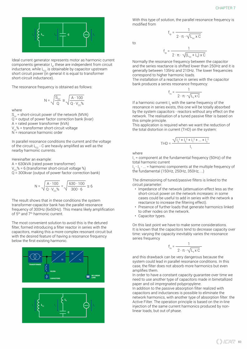
Ideal current generator represents motor as harmonic current components generator Ih these are independent from circuit inductance while LCC is obtainable by capacitor upstream short circuit power (in general it is equal to transformer short-circuit inductance)
The resonance frequency is obtained as follows
N =SCC
QA 100Q VCC
whereScc = short-circuit power of the network (MVA)Q = output of power factor correction bank (kvar)A = rated power transformer (kVA)Vcc = transformer short-circuit voltageN = resonance harmonic order
In parallel resonance conditions the current and the voltage of the circuit LCC - C are heavily amplified as well as the nearby harmonic currents
Hereinafter an exampleA = 630kVA (rated power transformer)VCC = 6 (transformer short-circuit voltage )Q = 300kvar (output of power factor correction bank)
N = = 6A 100Q VCC
630 100300 6
The result shows that in these conditions the system transformer-capacitor bank has the parallel resonance frequency of 300Hz (6x50Hz) This means likely amplification of 5th and 7th harmonic current
The most convenient solution to avoid this is the detuned filter formed introducing a filter reactor in series with the capacitors making this a more complex resonant circuit but with the desired feature of having a resonance frequency below the first existing harmonic
M
TRANSFORMER
FILTER
CAPACITORS
NO LINEARLOAD
It Ic IhLcc
C
Lf
With this type of solution the parallel resonance frequency is modified from
frp = 1
2 π Lcc x C
to
frp = 1
2 π (Lcc + Lf) x C
Normally the resonance frequency between the capacitor and the series reactance is shifted lower than 250Hz and it is generally between 135Hz and 210Hz The lower frequencies correspond to higher harmonic loadsThe installation of a reactance in series with the capacitor bank produces a series resonance frequency
frs = 1
2 π Lf x C
If a harmonic current Ih with the same frequency of the resonance in series exists this one will be totally absorbed by the system capacitors - reactors without any effect on the network The realisation of a tuned passive filter is based on this simple principleThis application is required when we want the reduction of the total distortion in current (THD) on the system
THD = I3
2 + I52 + I7
2 + + In2
I1
whereI1 = component at the fundamental frequency (50Hz) of the total harmonic currentI3 - I5 - = harmonic components at the multiple frequency of the fundamental (150Hz 250Hz 350Hz )
The dimensioning of tunedpassive filters is linked to the circuit parameter
bull Impedance of the network (attenuation effect less as the short-circuit power on the network increases in some cases could be useful to add in series with the network a reactance to increase the filtering effect)
bull Presence of further loads that generate harmonics linked to other nodes on the network
bull Capacitor types
On this last point we have to make some considerationsIt is known that the capacitors tend to decrease capacity over time varying the capacity inevitably varies the resonance series frequency
frs = 1
2 π Lf x C
and this drawback can be very dangerous because the system could lead in parallel resonance conditions In this case the filter does not absorb more harmonics but even amplifies themIn order to have a constant capacity guarantee over time we need to use another type of capacitors made in bimetallized paper and oil impregnated polypropyleneIn addition to the passive absorption filter realized with capacitors and inductances is possible to eliminate the network harmonics with another type of absorption filter the Active Filter The operation principle is based on the in-line injection of the same current harmonics produced by non-linear loads but out of phase
84
CHAPTER 7
Power factor correctionin presence of distorted voltageIn many industrial electrical systems or in the tertiary sector the presence of non-linear loads (inverter welding filament free lamps computers drives etc) causes a distortion of the current which is synthesized by the THDI numeric parameter if the current is sinusoidal his THDI is zero more the current is deformed so much higher is its THDIIn electrical currents with very deformed currents the power factor correction equipment are carried out in a filter banks (or block or blocked or detuned if you prefer) or rather with inductors that prevent harmonic current to reach and damage the capacitor Usually the supply voltage remains sinusoidal even if a very deformed current flows in the plant however if the MVLV transformer impedance is high the voltage may also be affected by deformation this impedance crossed by a distorted current will create a voltage drop equally distorted causing on LV users a non-sinusoidal supply voltage (or with a certain THDVR)It is rare that the THDVR reaches 8 (limit of IEC 50160) this happens for example when the MVLV transformer is characterized by a high series impedance andor is overloaded (saturation)In a plant with distorted voltage there will be problems of various types depending on the utilities (breakage or malfunction of electronic parts such as relays plc controller computers production beyond the acceptable tolerances etc)Regarding the power factor correction a high THDVR creates problems for the blocking reactors used in power factor correction banks These can saturate and overheat for overload up to be damaged causing the out of service of the power factor correction bank andor problems to the capacitorsThis will result in an economic loss (payment of penalties for low cosφ) and technical because the plant will run through by a higher current resulting in conductors additional overhead (cables bars) and the transformerFor this problem ICAR has developed a dedicated solution the MULTImatic FD25V (for 400V network) and FD70V (for 690V network) power factor correction ranges They are made with sound heavy dutybimetallized paper capacitors with high performance electronic instrumentation for the electrical parameters control high linearity reactance allow them to bear up to 8 THDVR continuously
Power factor correctionin the presence of a photovoltaic system in spot tradingIf on electrical plant of an industrial user is added a photovoltaic system the active power drawn from the supply is reduced because of the power supplied by the photovoltaic system and consumed by the plant (consumption)Therefore it changes the relationship between reactive power and active energy drawn from the network and consequently the power factor is lower than the same system without photovoltaicWe must therefore pay particular attention to the power factor correction not to have any penalties for low cosφ that could seriously erode the economic benefits of the photovoltaic systemThe power factor correction will be reviewed both for installed capacity both for construction type In fact increasing the power factor corrector power you will modify the resonance conditions with the MVLV transformer which supply the systemWhen the photovoltaic system has more power than the users one or if it is possible that power is introduced to the network the power factor corrector must also be able to run on the four quadrants The two standard quadrants are related to the plant operation as a user that absorbs from the network both active and inductive reactive power while the two quadrants related on the plant functioning as a generator it provides the network active power but it absorbs the inductive reactive power (quadrants of generation
All ICAR range of cosφ electronic controllers are able to operate in four quadrants running two different cosφ targets to optimize the system economic performanceTo manage the cogeneration quadrants you can alter some parameters settings It is advisable to enter a value equal to 1 to optimize the yield of the PFC Bank Refer to the manuals of the controllers for more detailsTo get the maximum benefit in the time allowed by the PFC Bank we recommend to use bimetallized paper capacitors the only ones that guarantee a useful life comparable to the photovoltaic system one

81
CHAPTER 7CHAPTER 7
Power factor correction How manyThe choice of capacitor bank to install in a system is closely depended from
bull cosφ2 value that we would obtainbull cosφ1 starting valuebull installed active power
By the following equation
QC = P middot (tanφ1 ndash tanφ2)
φ1φ2
Can be also written QC = k middot P
where the parameter k is easily calculated using Table 1 (in APPENDIX)As example if we have installed a load that absorbs an active power of 300 kW having a power factor 07 and we want to increase it until 097From the table 1 we find k = 0770and therefore
QC = 0770 middot 300 = 231 kvar
whereQC = required capacitors reactive output (kvar)P = active power (kW)QL QLrsquo = inductive reactive output before and after the installation of the capacitor bankA Arsquo= apparent power before and after the power factor correction (kVA)
A typical example of power factor correction sometimes not much considered but surely important concerns the power factor correction of transformers for the distribution of energyIt is essentially a fixed power factor correction that must compensate for the reactive power absorbed by the transformer in its no load condition (this happens often during the night) The calculation of the needed reactive output is very easy and it bases itself on this equation
QC = I0 AN
100
whereI0 = magnetising current of the transformerAN = apparent rated power in kVA of the transformer
If we donrsquot have these parameters it is convenient to use thefollowing table
Power transformer[kVA]
Oil[kvar]
Resin[kvar]
10 1 1520 2 1750 4 275 5 25
100 5 25160 7 4
200 75 5
250 8 75315 10 75400 125 8500 15 10630 175 125800 20 15
1000 25 1751250 30 201600 35 222000 40 252500 50 353150 60 50
Another very important example of power factor correction concerns asynchronous three-phase motors that areindividually correctedThe reactive power likely needed is reported on following table
Motor power Required reactive power [kvar]
HP KW 3000rpm
1500rpm
1000rpm
750 rpm
500rpm
04 055 ndash ndash 05 05 ndash1 073 05 05 06 06 ndash2 147 08 08 1 1 ndash3 221 1 1 12 16 ndash5 368 16 16 2 25 ndash7 515 2 2 25 3 ndash
10 736 3 3 4 4 5
15 11 4 5 5 6 630 221 10 10 10 12 1550 368 15 20 20 25 25
100 736 25 30 30 30 40150 110 30 40 40 50 60200 147 40 50 50 60 70250 184 50 60 60 70 80
Be careful the capacitor output must not be dimensioned too high for individual compensated machines where the capacitor is directly connected with the motor terminals The capacitor placed in parallel may act as a generator for the motor which will cause serious overvoltages (self-excitation phenomena) In case of wound rotor motor the reactive power of the capacitor bank must be increased by 5
82
CHAPTER 7
Power factor correctiontechnical reasonsRecent energy market deregulation along with new potential energy supplier rising had lead to many and different type of invoicing which are not very clear in showing Power Factor up However as energy final price is steady growing to correct power factor is becoming more and more convenient In most of the cases power factor improvement device prime cost is paid back in few monthsTechnical-economical advantages of the installation of acapacitor bank are the following
bull Decrease of the losses in the network and on the transformers caused by the lower absorbed current
bull Decrease of voltage drops on linesbull Optimisation of the system sizing
The current I that flows in the system is calculated by
I = P
3 V cosφ
whereP = Active powerV = Nominal voltage
While cosφ increases with the same absorbed power we can obtain a reduction in the value of the current and as a consequence the losses in the network and on the transformers are reducedTherefore we have an important saving on the size of electrical equipment used on a system The best system sizing has some consequence on the line voltage drop We can easily see that looking at the following formula
∆V = R + X PV
QV
whereP = Active power on the network (kW)Q = Reactive power on the network (kvar)while R is the cable resistance and X its reactance (RltltX)
The capacitor bank installation reduces Q so we have a lower voltage drop If for a wrong calculation of the installed capacitor bank value the reactive part of the above equation becomes negative instead of a reduction of the voltage drop we have an increasing of the voltage at the end of the line (Ferranti Effect) with dangerous consequence for the installed loads
Some examples clarify the concepts set out above
cosφ Power loss1 [kW] Supplied active power2 [kW]
05 32 5006 23 6007 16 7008 13 8009 1 901 0 100
1 In function of cosφ from a copper cable 3 x 25mm2 100m long carrying 40kW at 400Vac2 By a 100kVA transformer in function of cosφ
As we can see as the power factor increases we have fewer losses in the network and more active power from the same KVAThis allows us to optimise on the system sizing
Power factor correctionHarmonics in the networkThe distortions of the voltage and current waveforms are generated by non-linear loads (inverter saturated transformers rectifier etc) and produce the following problems
bull On the AC motors we find mechanical vibration that can reduce expected life The increase of the losses creates overheating with consequent damaging of the insulating materials
bull In transformers they increase the copper and iron losses with possible damaging of the windings The presence of direct voltage or current could cause the saturation of the cores with consequent increasing of the magnetising current
bull The capacitors suffer from the overheating and the increasing of the voltage that reduce their life
The waveform of the current (or voltage) generated by a nonlinear load being periodical could be represented by the sum of many sinusoidal waves (a 50Hz component called fundamental and other components with multiple frequency of the fundamental component so called harmonics)
150
100
50
0
-50
-100
-1500 0005 001 0015 002
150
100
50
0
-50
-100
-1500 0005 001 0015 002
150
100
50
0
-50
-100
-1500 0005 001 0015 002
150
100
50
0
-50
-100
-1500 0005 001 0015 002
I = I1 + I2 + I3 + + In
It is not advisable to install the power factor correction without considering the harmonic content of a systemThis is because even if we could manufacture capacitors that can withstand high overloads capacitors produce an increase of harmonic content with the negative effects just seenWe speak about resonance phenomena when an inductive reactance is equal to the capacitive one
2πf L = 12πf C
M
TRANSFORMER
CAPACITORS
NO LINEARLOAD
83
CHAPTER 7CHAPTER 7
Ihl Ihc IhLcc C
Ideal current generator represents motor as harmonic current components generator Ih these are independent from circuit inductance while LCC is obtainable by capacitor upstream short circuit power (in general it is equal to transformer short-circuit inductance)
The resonance frequency is obtained as follows
N =SCC
QA 100Q VCC
whereScc = short-circuit power of the network (MVA)Q = output of power factor correction bank (kvar)A = rated power transformer (kVA)Vcc = transformer short-circuit voltageN = resonance harmonic order
In parallel resonance conditions the current and the voltage of the circuit LCC - C are heavily amplified as well as the nearby harmonic currents
Hereinafter an exampleA = 630kVA (rated power transformer)VCC = 6 (transformer short-circuit voltage )Q = 300kvar (output of power factor correction bank)
N = = 6A 100Q VCC
630 100300 6
The result shows that in these conditions the system transformer-capacitor bank has the parallel resonance frequency of 300Hz (6x50Hz) This means likely amplification of 5th and 7th harmonic current
The most convenient solution to avoid this is the detuned filter formed introducing a filter reactor in series with the capacitors making this a more complex resonant circuit but with the desired feature of having a resonance frequency below the first existing harmonic
M
TRANSFORMER
FILTER
CAPACITORS
NO LINEARLOAD
It Ic IhLcc
C
Lf
With this type of solution the parallel resonance frequency is modified from
frp = 1
2 π Lcc x C
to
frp = 1
2 π (Lcc + Lf) x C
Normally the resonance frequency between the capacitor and the series reactance is shifted lower than 250Hz and it is generally between 135Hz and 210Hz The lower frequencies correspond to higher harmonic loadsThe installation of a reactance in series with the capacitor bank produces a series resonance frequency
frs = 1
2 π Lf x C
If a harmonic current Ih with the same frequency of the resonance in series exists this one will be totally absorbed by the system capacitors - reactors without any effect on the network The realisation of a tuned passive filter is based on this simple principleThis application is required when we want the reduction of the total distortion in current (THD) on the system
THD = I3
2 + I52 + I7
2 + + In2
I1
whereI1 = component at the fundamental frequency (50Hz) of the total harmonic currentI3 - I5 - = harmonic components at the multiple frequency of the fundamental (150Hz 250Hz 350Hz )
The dimensioning of tunedpassive filters is linked to the circuit parameter
bull Impedance of the network (attenuation effect less as the short-circuit power on the network increases in some cases could be useful to add in series with the network a reactance to increase the filtering effect)
bull Presence of further loads that generate harmonics linked to other nodes on the network
bull Capacitor types
On this last point we have to make some considerationsIt is known that the capacitors tend to decrease capacity over time varying the capacity inevitably varies the resonance series frequency
frs = 1
2 π Lf x C
and this drawback can be very dangerous because the system could lead in parallel resonance conditions In this case the filter does not absorb more harmonics but even amplifies themIn order to have a constant capacity guarantee over time we need to use another type of capacitors made in bimetallized paper and oil impregnated polypropyleneIn addition to the passive absorption filter realized with capacitors and inductances is possible to eliminate the network harmonics with another type of absorption filter the Active Filter The operation principle is based on the in-line injection of the same current harmonics produced by non-linear loads but out of phase
84
CHAPTER 7
Power factor correctionin presence of distorted voltageIn many industrial electrical systems or in the tertiary sector the presence of non-linear loads (inverter welding filament free lamps computers drives etc) causes a distortion of the current which is synthesized by the THDI numeric parameter if the current is sinusoidal his THDI is zero more the current is deformed so much higher is its THDIIn electrical currents with very deformed currents the power factor correction equipment are carried out in a filter banks (or block or blocked or detuned if you prefer) or rather with inductors that prevent harmonic current to reach and damage the capacitor Usually the supply voltage remains sinusoidal even if a very deformed current flows in the plant however if the MVLV transformer impedance is high the voltage may also be affected by deformation this impedance crossed by a distorted current will create a voltage drop equally distorted causing on LV users a non-sinusoidal supply voltage (or with a certain THDVR)It is rare that the THDVR reaches 8 (limit of IEC 50160) this happens for example when the MVLV transformer is characterized by a high series impedance andor is overloaded (saturation)In a plant with distorted voltage there will be problems of various types depending on the utilities (breakage or malfunction of electronic parts such as relays plc controller computers production beyond the acceptable tolerances etc)Regarding the power factor correction a high THDVR creates problems for the blocking reactors used in power factor correction banks These can saturate and overheat for overload up to be damaged causing the out of service of the power factor correction bank andor problems to the capacitorsThis will result in an economic loss (payment of penalties for low cosφ) and technical because the plant will run through by a higher current resulting in conductors additional overhead (cables bars) and the transformerFor this problem ICAR has developed a dedicated solution the MULTImatic FD25V (for 400V network) and FD70V (for 690V network) power factor correction ranges They are made with sound heavy dutybimetallized paper capacitors with high performance electronic instrumentation for the electrical parameters control high linearity reactance allow them to bear up to 8 THDVR continuously
Power factor correctionin the presence of a photovoltaic system in spot tradingIf on electrical plant of an industrial user is added a photovoltaic system the active power drawn from the supply is reduced because of the power supplied by the photovoltaic system and consumed by the plant (consumption)Therefore it changes the relationship between reactive power and active energy drawn from the network and consequently the power factor is lower than the same system without photovoltaicWe must therefore pay particular attention to the power factor correction not to have any penalties for low cosφ that could seriously erode the economic benefits of the photovoltaic systemThe power factor correction will be reviewed both for installed capacity both for construction type In fact increasing the power factor corrector power you will modify the resonance conditions with the MVLV transformer which supply the systemWhen the photovoltaic system has more power than the users one or if it is possible that power is introduced to the network the power factor corrector must also be able to run on the four quadrants The two standard quadrants are related to the plant operation as a user that absorbs from the network both active and inductive reactive power while the two quadrants related on the plant functioning as a generator it provides the network active power but it absorbs the inductive reactive power (quadrants of generation
All ICAR range of cosφ electronic controllers are able to operate in four quadrants running two different cosφ targets to optimize the system economic performanceTo manage the cogeneration quadrants you can alter some parameters settings It is advisable to enter a value equal to 1 to optimize the yield of the PFC Bank Refer to the manuals of the controllers for more detailsTo get the maximum benefit in the time allowed by the PFC Bank we recommend to use bimetallized paper capacitors the only ones that guarantee a useful life comparable to the photovoltaic system one