CH 7: GAS-TURBINE ENGINES Prepared by Dr. …...CH 7: GAS-TURBINE ENGINES Prepared by Dr. Assim Al...
40
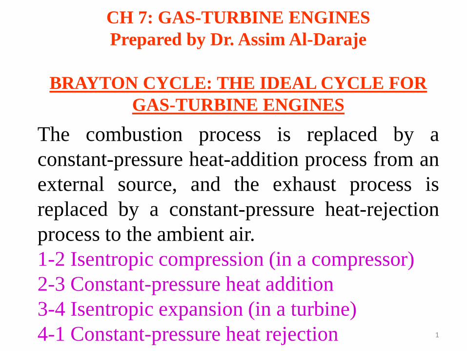
CH 7: GAS-TURBINE ENGINES Prepared by Dr. Assim Al-Daraje BRAYTON CYCLE: THE IDEAL CYCLE FOR GAS-TURBINE ENGINES The combustion process is replaced by a constant-pressure heat-addition process from an external source, and the exhaust process is replaced by a constant-pressure heat-rejection process to the ambient air. 1-2 Isentropic compression (in a compressor) 2-3 Constant-pressure heat addition 3-4 Isentropic expansion (in a turbine) 4-1 Constant-pressure heat rejection 1
Transcript of CH 7: GAS-TURBINE ENGINES Prepared by Dr. …...CH 7: GAS-TURBINE ENGINES Prepared by Dr. Assim Al...
CH 7: GAS-TURBINE ENGINES Prepared by Dr. Assim Al-Daraje
BRAYTON CYCLE: THE IDEAL CYCLE FOR
GAS-TURBINE ENGINES
The combustion process is replaced by a constant-pressure heat-addition process from an external source, and the exhaust process is replaced by a constant-pressure heat-rejection process to the ambient air. 1-2 Isentropic compression (in a compressor) 2-3 Constant-pressure heat addition 3-4 Isentropic expansion (in a turbine) 4-1 Constant-pressure heat rejection 1

2
GAS-TURBINE ENGINES
3
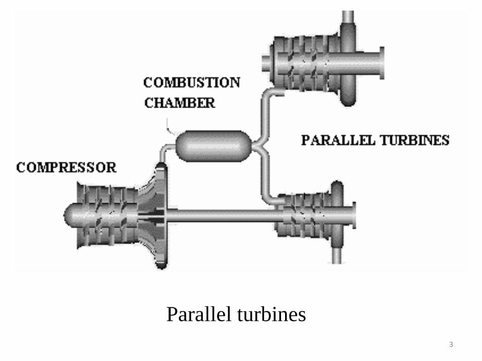
Parallel turbines
4
5
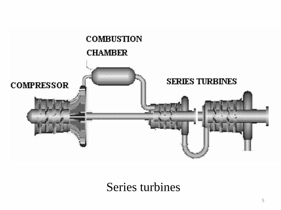
Series turbines
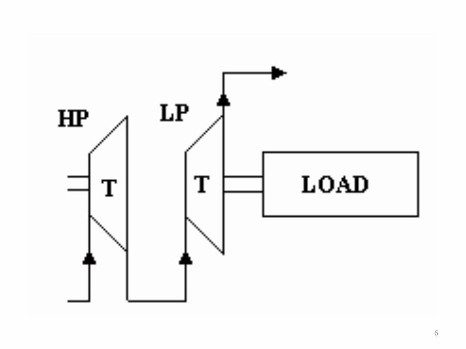
6
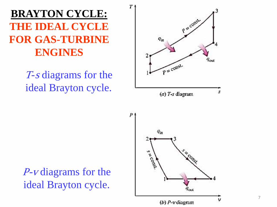
T-s diagrams for the ideal Brayton cycle.
7
BRAYTON CYCLE: THE IDEAL CYCLE FOR GAS-TURBINE
ENGINES
P-v diagrams for the ideal Brayton cycle.

( ) ( )
( ) ( )
cyclerealinincreases
12
cyclerealindecreases
43
trequiremenpowercompressor
12
outputpowerturbine
43
TTcTTcw
TTcTTcw
apapactual
ppideal
−−−=
−−−=
8
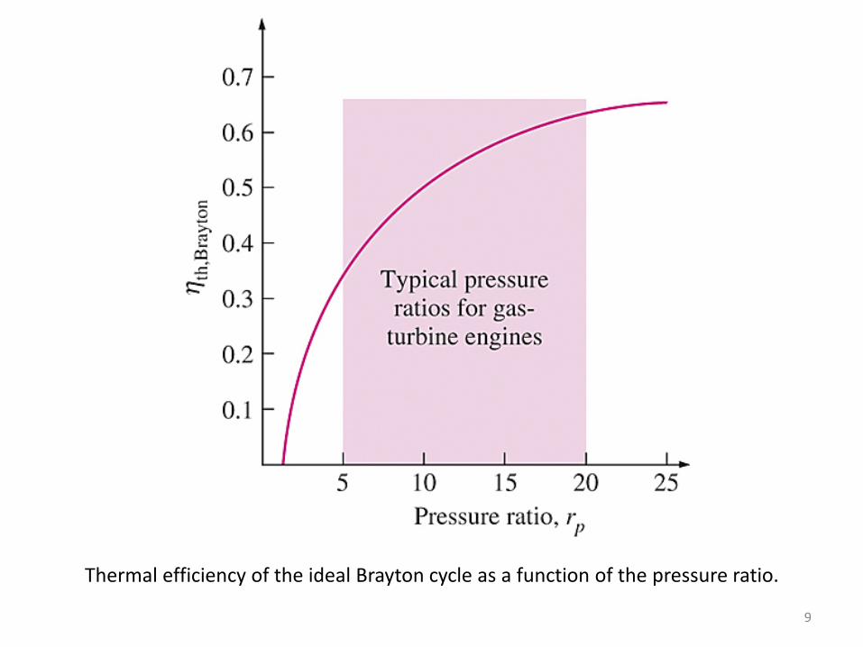
Thermal efficiency of the ideal Brayton cycle as a function of the pressure ratio.
9
10
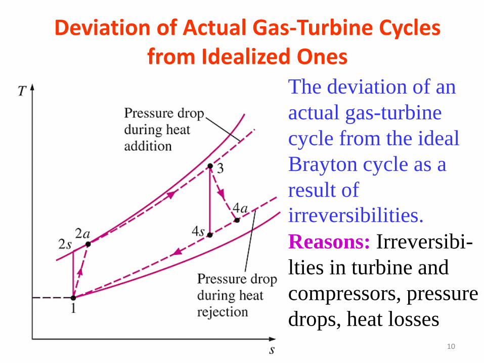
Deviation of Actual Gas-Turbine Cycles from Idealized Ones
The deviation of an actual gas-turbine cycle from the ideal Brayton cycle as a result of irreversibilities. Reasons: Irreversibi-lties in turbine and compressors, pressure drops, heat losses
11
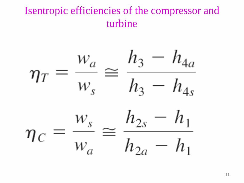
Isentropic efficiencies of the compressor and turbine
12
Development of Gas Turbines
1. Increasing the turbine inlet (or firing) temperatures.
2. Increasing the efficiencies of turbomachinery components (turbines, compressors):
Adding modifications to the basic cycle (intercooling, regeneration or recuperation, and reheating).
13
THE BRAYTON CYCLE WITH REGENERATION In gas-turbine engines, the temperature of the exhaust gas leaving the turbine is often considerably higher than the temperature of the air leaving the compressor. Therefore, the high-pressure air leaving the compressor can be heated by the hot exhaust gases in a counter-flow heat exchanger (a regenerator or a recuperator). The thermal efficiency of the Brayton cycle increases as a result of regeneration since less fuel is used for the same work output.

14
A gas-turbine engine with regenerator.
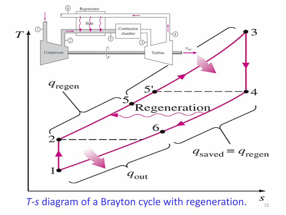
15 T-s diagram of a Brayton cycle with regeneration.
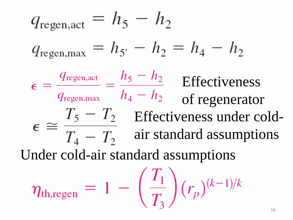
16
Effectiveness of regenerator
Effectiveness under cold-air standard assumptions
Under cold-air standard assumptions
17
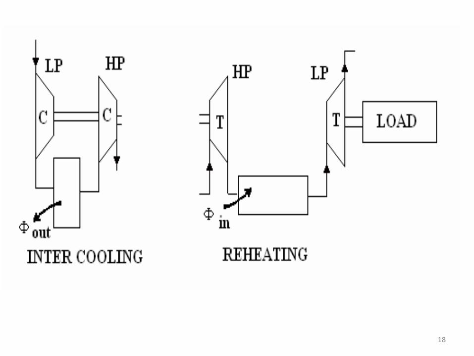
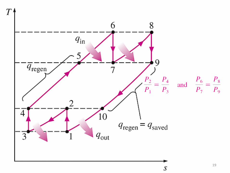
THE BRAYTON CYCLE WITH INTERCOOLING, REHEATING, AND REGENERATION
A gas-turbine engine with two-stage compression with intercooling, two-stage expansion with reheating, and regeneration and its T-s diagram.
For minimizing work input to compressor and maximizing work output from turbine:
18
19
20
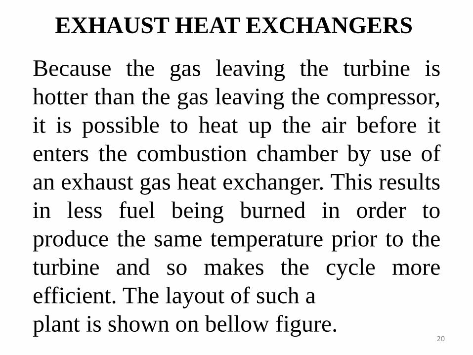
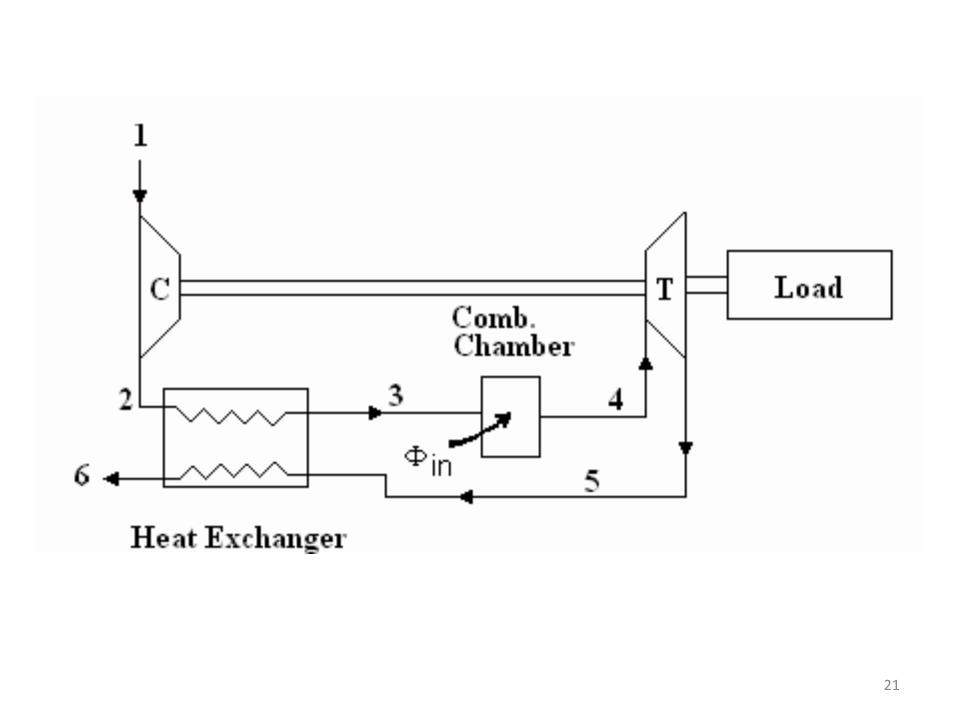
EXHAUST HEAT EXCHANGERS
Because the gas leaving the turbine is hotter than the gas leaving the compressor, it is possible to heat up the air before it enters the combustion chamber by use of an exhaust gas heat exchanger. This results in less fuel being burned in order to produce the same temperature prior to the turbine and so makes the cycle more efficient. The layout of such a plant is shown on bellow figure.
21
22
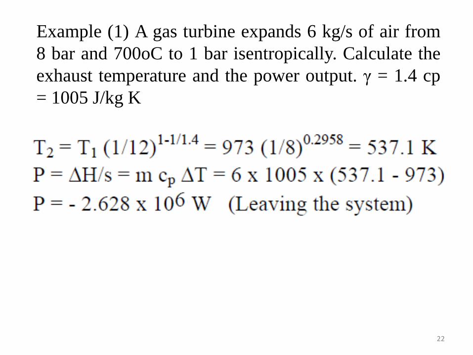
Example (1) A gas turbine expands 6 kg/s of air from 8 bar and 700oC to 1 bar isentropically. Calculate the exhaust temperature and the power output. γ = 1.4 cp = 1005 J/kg K
23
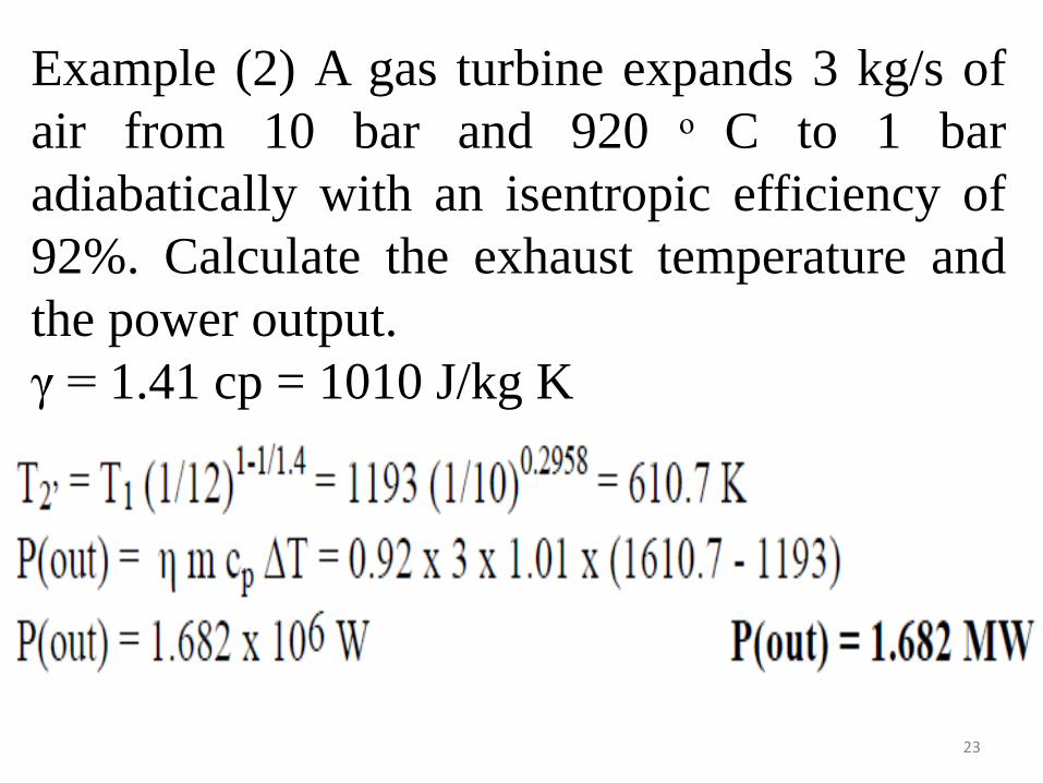
Example (2) A gas turbine expands 3 kg/s of air from 10 bar and 920 ͦ C to 1 bar adiabatically with an isentropic efficiency of 92%. Calculate the exhaust temperature and the power output. γ = 1.41 cp = 1010 J/kg K
24
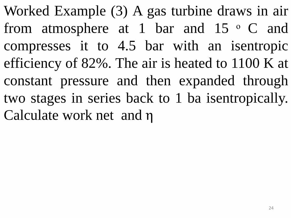
Worked Example (3) A gas turbine draws in air from atmosphere at 1 bar and 15 ͦ C and compresses it to 4.5 bar with an isentropic efficiency of 82%. The air is heated to 1100 K at constant pressure and then expanded through two stages in series back to 1 ba isentropically. Calculate work net and η
25
26
27
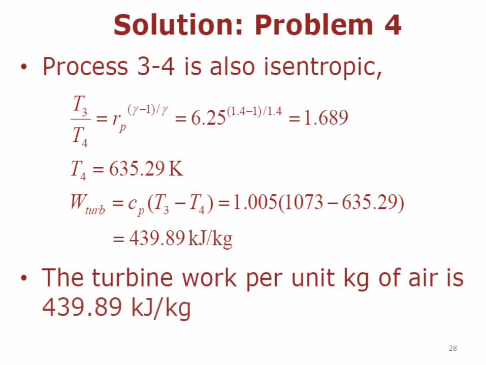
28
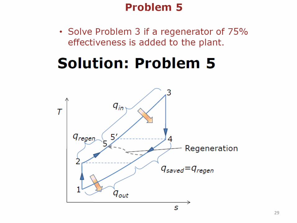
29

30
31
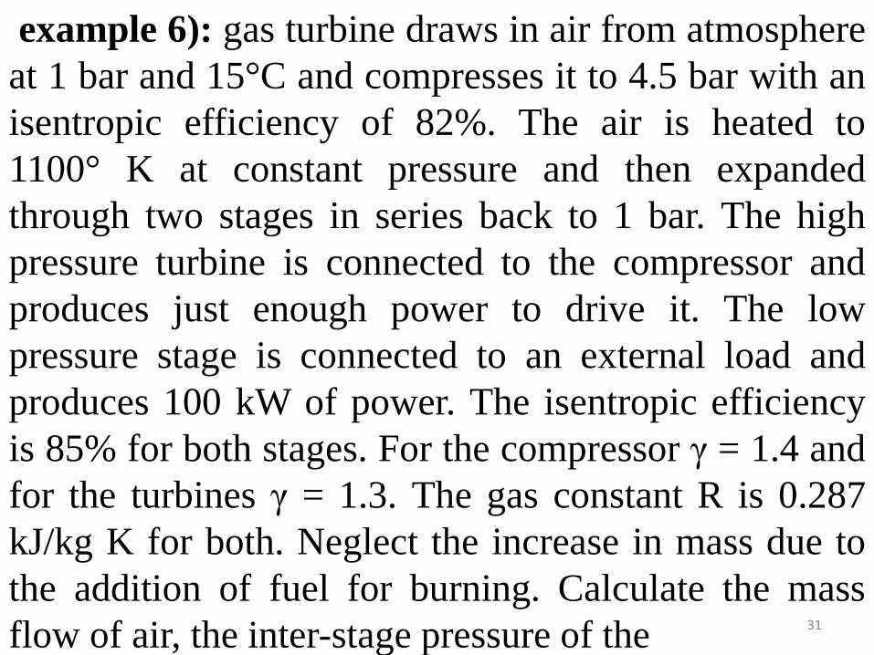
example 6): gas turbine draws in air from atmosphere at 1 bar and 15°C and compresses it to 4.5 bar with an isentropic efficiency of 82%. The air is heated to 1100° K at constant pressure and then expanded through two stages in series back to 1 bar. The high pressure turbine is connected to the compressor and produces just enough power to drive it. The low pressure stage is connected to an external load and produces 100 kW of power. The isentropic efficiency is 85% for both stages. For the compressor γ = 1.4 and for the turbines γ = 1.3. The gas constant R is 0.287 kJ/kg K for both. Neglect the increase in mass due to the addition of fuel for burning. Calculate the mass flow of air, the inter-stage pressure of the
32
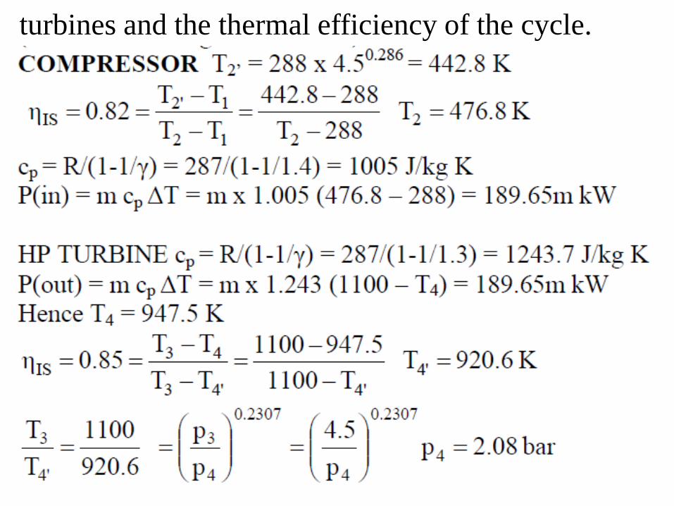
turbines and the thermal efficiency of the cycle.
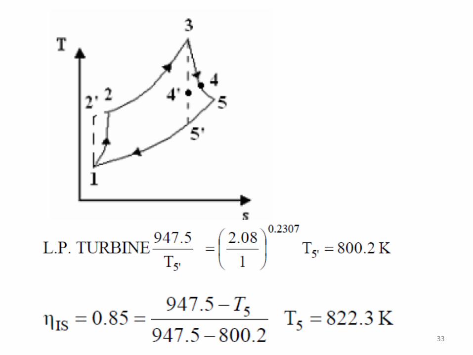
33

34
35
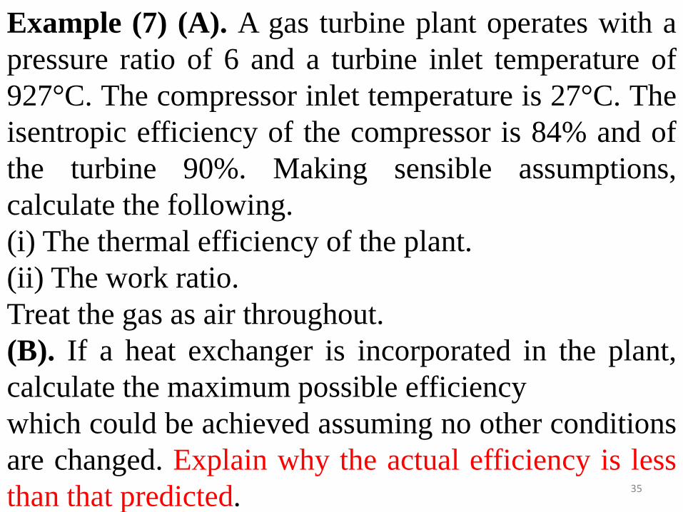
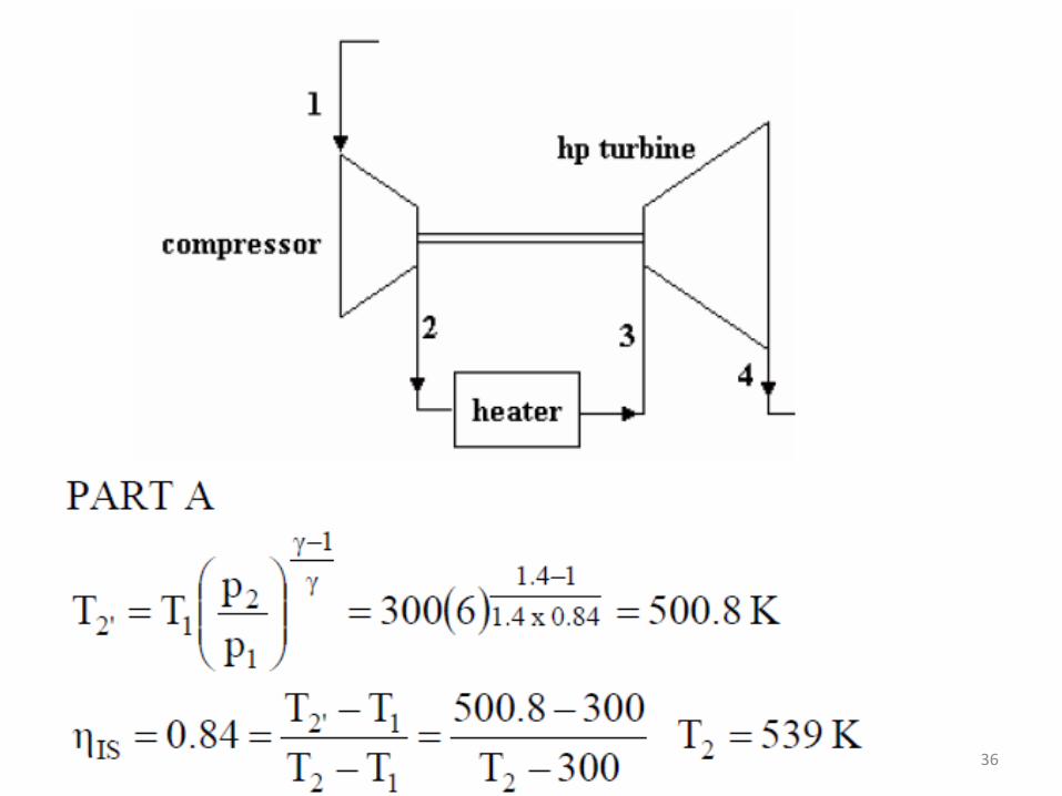
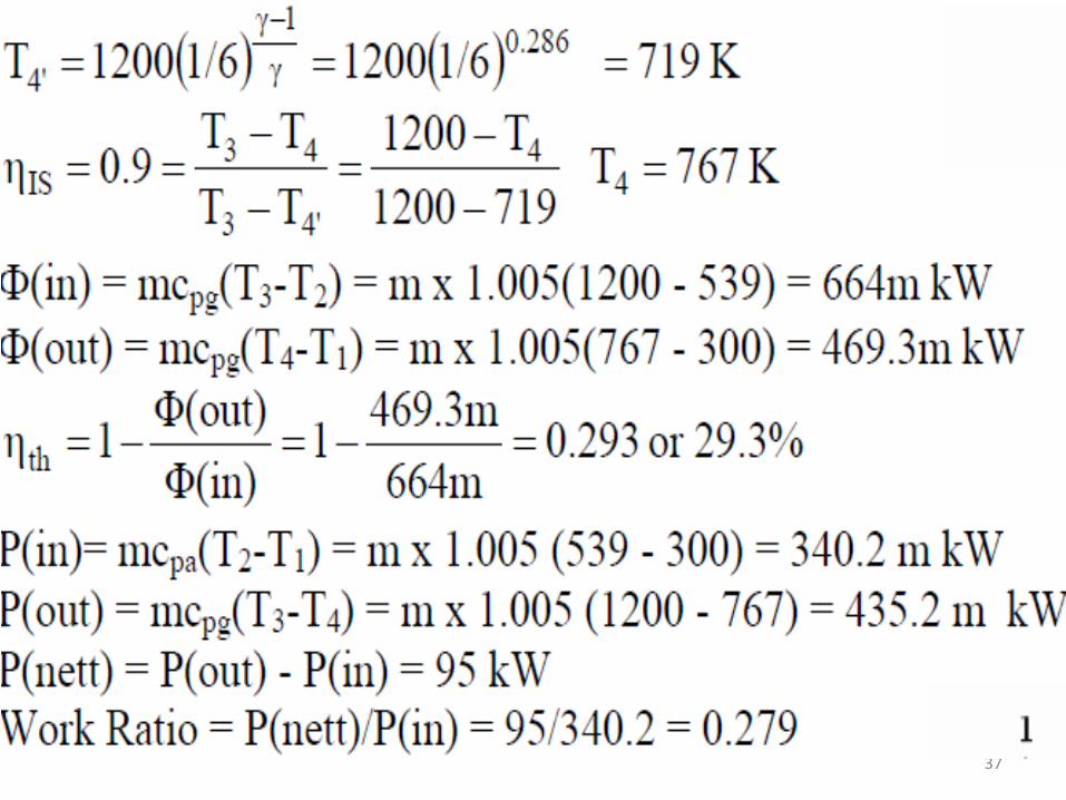
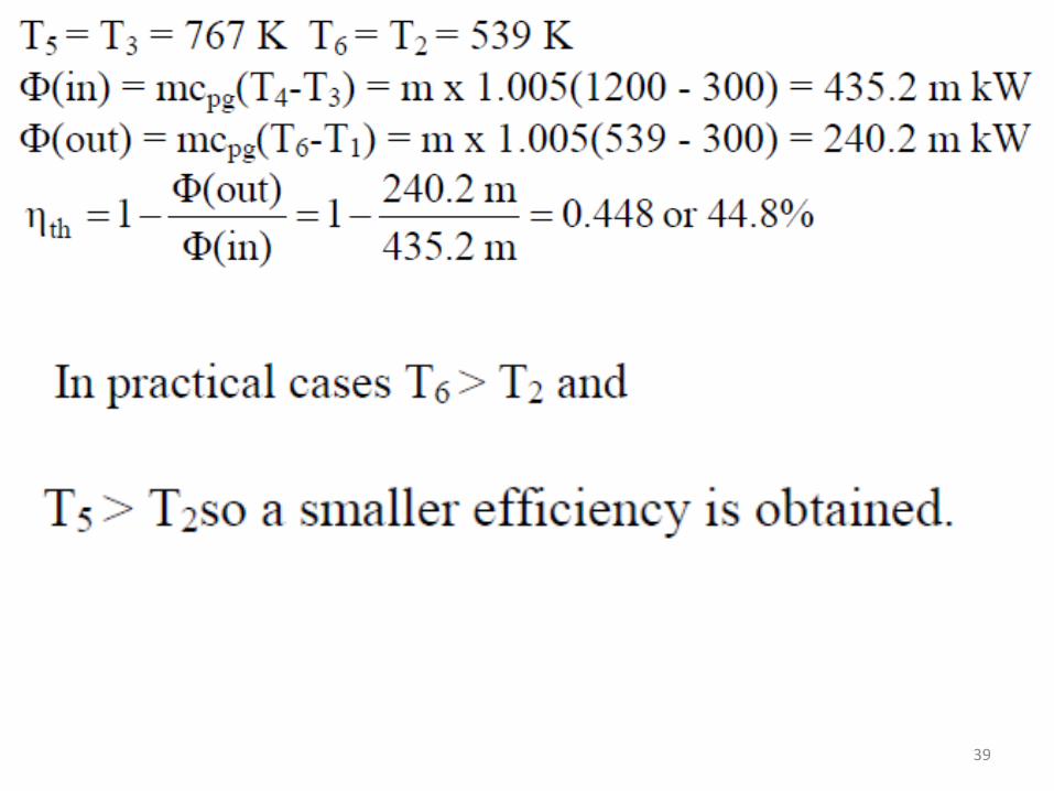
Example (7) (A). A gas turbine plant operates with a pressure ratio of 6 and a turbine inlet temperature of 927°C. The compressor inlet temperature is 27°C. The isentropic efficiency of the compressor is 84% and of the turbine 90%. Making sensible assumptions, calculate the following. (i) The thermal efficiency of the plant. (ii) The work ratio. Treat the gas as air throughout. (B). If a heat exchanger is incorporated in the plant, calculate the maximum possible efficiency which could be achieved assuming no other conditions are changed. Explain why the actual efficiency is less than that predicted.
36
37
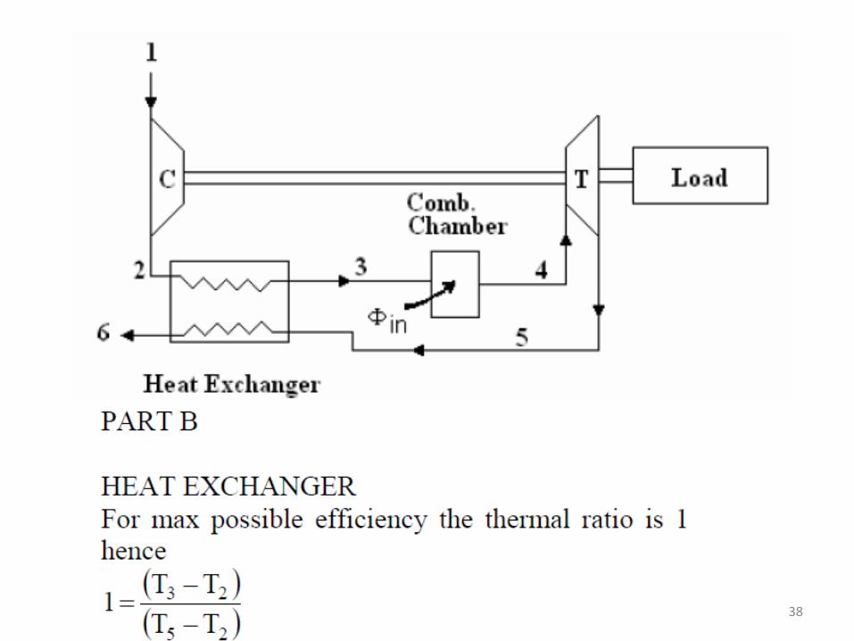
38
39
40