CH 2 Final - elaw.org2.pdf · 20 deg 26 min 02 sec North to 20 deg 27 min 43 sec North and...
23
The Tata Power Company Ltd. EIA Report for 1000 MW Coal Based Thermal Power Plant at Naraj Marthapur, Cuttack, Orissa SGS India Private Limited 12 CHAPTER 2 PROJECT DESCRIPTION 2.1 Need for the Project The Orissa government’s policy seeks to promote power generation both by Independent Power Producers (IPPs) and captive power plants (CPPs). The newly formed GRIDCO has been empowered to negotiate fair and equitable power purchase agreements with IPPs and with industries owning captive power plants supplying surplus power to the State Power Grid. It also provides for sales to industries on payment of wheeling charges. Tata Steel has proposed to establish 6 MTPA capacity steel plant in five phases at Kalinganagar Industrial Complex near Duburi village about 100 km from Talcher in Orissa State. Tata Steel has formed a Joint Venture company with TPC to take care of the power needs of the Tata Steel’s plants in Eastern Region. In line with this, TPC is contemplating setting up a power plant in Orissa to meet the external power demand of Tata Steel’s proposed Steel Plant at Kalinganagar. In addition, TPC has also signed MoU with GRIDCO to sell power to the extent of 250 MW from the same plant. Table 2.1 presents the power demand scenario. Considering the above, Tata Power Company proposes to set up a coal based thermal power plant of 1000 MW capacity near Naraj Marthapur, Cuttack Sadar Tehsil, Cuttack District in Orissa State. Table 2.1 Allocation of Capacity in MW Year Tata Steel GRIDCO TPC Total Remarks 2009-10 250 250 250 750 TPC’s requirement is primarily intended for achieve reliable power 2011-12 500 250 250 1000 Cumulative demand
Transcript of CH 2 Final - elaw.org2.pdf · 20 deg 26 min 02 sec North to 20 deg 27 min 43 sec North and...

The Tata Power Company Ltd.
EIA Report for 1000 MW Coal Based Thermal Power Plant at Naraj Marthapur, Cuttack, Orissa
SGS India Private Limited
12
CHAPTER 2
PROJECT DESCRIPTION
2.1 Need for the Project
The Orissa government’s policy seeks to promote power generation both by
Independent Power Producers (IPPs) and captive power plants (CPPs). The newly
formed GRIDCO has been empowered to negotiate fair and equitable power
purchase agreements with IPPs and with industries owning captive power plants
supplying surplus power to the State Power Grid. It also provides for sales to
industries on payment of wheeling charges.
Tata Steel has proposed to establish 6 MTPA capacity steel plant in five phases at
Kalinganagar Industrial Complex near Duburi village about 100 km from Talcher
in Orissa State. Tata Steel has formed a Joint Venture company with TPC to take
care of the power needs of the Tata Steel’s plants in Eastern Region. In line
with this, TPC is contemplating setting up a power plant in Orissa to meet the
external power demand of Tata Steel’s proposed Steel Plant at Kalinganagar. In
addition, TPC has also signed MoU with GRIDCO to sell power to the extent
of 250 MW from the same plant. Table 2.1 presents the power demand scenario.
Considering the above, Tata Power Company proposes to set up a coal based
thermal power plant of 1000 MW capacity near Naraj Marthapur, Cuttack Sadar
Tehsil, Cuttack District in Orissa State.
Table 2.1
Allocation of Capacity in MW
Year Tata
Steel
GRIDCO TPC Total Remarks
2009-10 250 250 250 750 TPC’s requirement is
primarily intended for
achieve reliable power
2011-12 500 250 250 1000 Cumulative demand
The Tata Power Company Ltd.
EIA Report for 1000 MW Coal Based Thermal Power Plant at Naraj Marthapur, Cuttack, Orissa
SGS India Private Limited
13
2.2 Location
The proposed location for power plant is situated near Naraj Marthapur, Cuttack
Sadar Tehsil, in Cuttack District of Orissa State. The site is bounded by latitude
20 deg 26 min 02 sec North to 20 deg 27 min 43 sec North and longitude 85 deg
45 min 28 sec East to 85 deg 47 min 07 sec East. The area is about 990 acres. The
power plant capacity has been proposed to be 1000 MW (2x125 + 2x125 + 2x250
MW). The power plant site is located adjacent to an existing road connecting
Khurda, Chandaka, Barang, Gobindapur, proposed site and Naraj villages. The site
can be approached by road from Cuttack. Naraj Marthapur is a nearest railway
station located at a distance of about 750 m from the project site boundary on
Talcher- Khurda Road railway line of Eastern Railway Road railway line of
Eastern railway.
2.3 Selection of site
The site selection was done on the basis a Report by Central Mine Planning and
Development Institute (CMPDI), Ranchi, submitted to Central Electricity
Authority (CEA) in March 2004 for locating the thermal power plants in the state
of Orissa considering six (6) sites and further consideration of two (2) sites by
TCE Consulting Engineers. Details have been provided in Chapter 5.
2.4 Unit Size Selection
Considering the power requirement for the steel plant at Kalinganagar and the
commitment for power distribution to GRIDCO, the unit sizes for the proposed
power plant have been selected as a combination of a number of 125 MW units
and 250 MW units as given below:
2 X 125 MW + 2 X 125 MW + 2X250 MW = 1000 MW
2.5 Land Requirement & Plant Layout
The site is located on the northern and southern side of Puri Canal. Total land is
about 990 acres. The availability of land and minimum displacement have been
the factors for selecting the site in this fashion. River Mahanadi flows from west

The Tata Power Company Ltd.
EIA Report for 1000 MW Coal Based Thermal Power Plant at Naraj Marthapur, Cuttack, Orissa
SGS India Private Limited
14
to east on the northern side of the site. The site is more than a kilometre away
from the HFL of the river.
The main plant and coal storage area will be on the northern half to facilitate coal
receipt by railway wagons and fuel oil by rail tankers.
While the different auxiliary system with ash pond will be in the southern half.
Figure 2.1 shows the plant layout.
All facilities of the plant are laid out in close proximity to each other to the extent
practicable so as to minimise the extent of land required. The layout also
facilitates communication of men and movement of materials between the various
facilities both during initial construction and also during subsequent operation and
maintenance.
Out of the total 990 acres of land, the Govt. land is about 21%. 4% of land is
forest land which is dispersed in very small patches. The agricultural land mainly
consists of single crop category.
Ash pond area is 30 acres only. About 200 acres of land contiguous to the plant
area under the possession of the project consists of a hillock and that area will be
kept as green area with further plantation.
2.6 Power Generation Process
Power generation in thermal power plant is achieved by steam generation at high
temperature and pressure which is then used to run a turbine to generate
electricity. Coal is used as fuel for steam generation.
Steam generation requires heating demineralised water in the boiler at high
temperature and pressure. Steam at high temperature 5370C(±5
0C) and high
pressure (170 Kg/cm2) is fed to rotate the turbine to generate power. Spent steam
is converted into condensate by cooling in heat exchanger. Cooling water used in
heat exchanger is cooled in the cooling tower.
Exhaust gas after exchanging the heat is released at a temperature of 140oC
through a chimney.
Figure 2.2 shows the Process Flow Scheme.
Major issues and units in the process are described below.
The Tata Power Company Ltd.
EIA Report for 1000 MW Coal Based Thermal Power Plant at Naraj Marthapur, Cuttack, Orissa
SGS India Private Limited
15
2.7 Fuel Requirement & Transportation
At maximum continuous rating (MCR) condition based on Talcher coal having a
gross calorific value of 3700 k Cal / kg for 250 MW unit is 169 tonnes / hr and for
125 MW unit is 86 tonnes / hr. The maximum daily requirement of coal for all six
units would be about 16,368 tonnes per day.
LDO and HFO will be used as fuel for start up and flame support.
Coal from the Talcher Coal Fields which is at a distance of about 90 km from
power plant site is proposed to be transported by bottom-open rail wagons on the
rail route. A main broad gauge railway line of South eastern Railways is existing
at Naraj Marthapur Railway station which is located adjacent to the proposed
plant boundary. A take off point is to be constructed before the station for coal
rakes to enter into the power station area. A Merry Go-Round (MGR) system is
proposed within the proposed plant site.
HFO and LDO required for the power plant operation be transported from the
nearest terminal by rail wagons (tankers). The peak requirement of LDO will be
during light up and commissioning where as the peak requirement of HFO will be
during the trial operation. Ten (10) days of oil storage is envisaged.
2.8 Water Requirement
The source of water is Mahanadi river. The daily raw water requirement for the
proposed power plant, including cooling tower, SG make up plus other services is
estimated to be 96684 m3/ day. The above quantity of raw water will be drawn by
pumping and conveying water through large diameter piping from Mahanadi
located at about 3 km from the proposed plant site. The total water requirement is
given in Table 2.2.
Water balance diagram is given in Figure 2.3.

The Tata Power Company Ltd.
EIA Report for 1000 MW Coal Based Thermal Power Plant at Naraj Marthapur, Cuttack, Orissa
SGS India Private Limited
16
Table 2.2
Water Requirement
Item Quantity
m3/ day
CW make up for condenser and other
auxiliaries
74112
Main Clarifier blowdown 2400
DM clarifier blowdown 120
Service Water 16800
Plant & Colony potable water 480
DM water for SG makeup, ACW makeup 2448
DM plant regeneration 244
Filter backwash 80
Total raw water requirement 96684
Cooling water make up constitutes 76% of all water requirements. So optimisation
of cycle of concentration (COC) in Cooling Tower decides the water requirement.
As mentioned in TOR Point No. 21, optimisation of COC has been carried out to
reduce water requirement. A high COC of 4.5 has been considered. Table 2.3
shows then cooling water requirement break-up.
Table 2.3
CW System Make-up Requirements
Sl No Item Quantity (M3/day)
1. Cooling Tower (Evaporation + Drift Losses) 14400 x 4 towers = 57600
2.* Condenser CW System Blow down* 4128 x 4 towers = 16512
3. CW Make-up requirement (item 1 + item 2) 57600 + 16512 = 74112
4. Concentration Ratio ‘C’ (item 3 / item 2) 4.5
2.9 Main Power Plant Units
Steam Generator and Accessories
The steam generator (SG) would be designed for firing 100% coal and would be
natural circulation drum type. The SG would be of two pass design, radiant, single
reheat, balanced draft, semi-outdoor type, rated to deliver 820 t / hr of superheated
steam at 155 atm, 540oC.

The Tata Power Company Ltd.
EIA Report for 1000 MW Coal Based Thermal Power Plant at Naraj Marthapur, Cuttack, Orissa
SGS India Private Limited
17
The SG would be designed to handle and burn HFO as secondary fuel up to 22.5
% MCR capacity for start-up and for flame stabilisation during low-load
operation. For unit light up and warm up purposes LDO shall be fired.
The steam generator would consist of water cooled furnace, radiant and
convection super-heaters, re-heaters, attemperators, economiser, regenerative air
heaters, steam coil air pre-heaters, etc. Soot blowers would be provided at
strategic locations and would be designed for sequential fully automatic operation
from the unit control room.
The draft plant would comprise of primary air fans , forced draft fans, and induced
draft fans. Electrostatic precipitator (ESP) and fly ash hoppers would be provided
for the collection of fly ash. The ESP shall be designed to achieve an outlet dust
concentration of 100 mg / Nm³ as per CREP norms. This will be achieved with
one field out of operation.
Steam Turbine Generator and Accessories
The selected steam turbine generators (STG) would be rated for 250 MW and 125
MW maximum continuous output at the generator terminals, with throttle steam
conditions of 150 ata and 538 o
C steam temperature and 0.1bar (a) back pressure.
The steam turbine would be a reheat extraction condensing turbine. The
regenerative cycle would consist of three low-pressure heaters, a variable pressure
de-aerator, two high pressure heaters, one drain cooler and one gland steam
condenser.
2 x 100% capacity condensate extraction pumps, one working and one standby,
would be provided for each unit. The pumps would be vertical, canister type,
multistage centrifugal pumps driven by AC motors.
3 x 50% capacity boiler feed pumps would be provided to pump the feed water
from the de-aerator to the steam generator through the high pressure heaters. The

The Tata Power Company Ltd.
EIA Report for 1000 MW Coal Based Thermal Power Plant at Naraj Marthapur, Cuttack, Orissa
SGS India Private Limited
18
boiler feed pumps would be horizontal, multistage, AC motor driven centrifugal
pumps of barrel type with variable speed hydraulic coupling.
A complete lubricating oil system will be provided for the steam turbine generator
unit. The control fluid system may be fully separated from the lubricating oil
system or integrated with the lube oil system as per the turbine manufacturer’s
standard. The lube oil system will be comprising of lube oil pumps, main oil tank,
lube oil coolers, lube oil filters, piping, valves fittings etc. The control fluid
system will have its own pumps, motors, coolers, strainers, piping, valves and
fittings.
A microprocessor based diagnostic and data management system complete with
vibration and other sensors will be provided for the steam turbine and all HT (6.6
kV) drives/ motors of boiler and turbine islands and CW pumps.
Fuel oil system
The fuel oil system will be designed for the use of heavy fuel oil (HFO) for start
up and flame stabilisation purposes. LDO will be used as fuel for light up and
warm up purposes.
Electrostatic Precipitators
Each steam generating unit would be provided with two (2) electrostatic
precipitators. Each precipitator will have two parallel gas paths, any of which can
be isolated for maintenance as and when required, keeping the other path in
operation. The overall efficiency of ESP should not be less than 99.89% with one
field remaining as operational standby. The design of ESP will be such that the
outlet dust-burden does not exceed 100 mg/Nm3 at 100% MCR with worst coal.
Chimney / stack
Three (3) reinforced concrete chimneys each of 275 m height will be provided for
six units (ie. one common chimney with separate flues for two units). Each

The Tata Power Company Ltd.
EIA Report for 1000 MW Coal Based Thermal Power Plant at Naraj Marthapur, Cuttack, Orissa
SGS India Private Limited
19
chimney will be provided with two steel flues. This would meet the requirement
of Indian Emission Regulation.
Raw Water Treatment
Since the river water is expected to have turbidity / suspended solids during
monsoon and the quality of influent water required for the various systems in the
plant is clarified water (with turbidity and suspended solids less than 20 ppm), it is
proposed to provide clariflocculator type clarifier for CW make up and plant
service. Another solids contact type clarifier is proposed to exclusively cater to the
DM plant. This clarifier will take care of any colloidal silica presence, which
cannot be removed by ion exchange units in the water treatment (WT) plant.
The clarified water from the main plant clarifier will be stored in a main plant
clarified water storage tank. The storage tank caters to the requirement of CW
make up and plant service. The clarified water from the DM plant clarifier will be
stored in DM plant clarified water storage tank of ten (10) hours storage.
DM Plant
This broadly consists of DM pre-treatment plant, filtration and DM plant. The DM
pre-treatment consists of i) Chlorination system in the form of sodium
hypochlorite to destroy organic matter and algae and ii) Alum dosing system for
the purpose of coagulation. The filtration plant consists of Four (4) vertical dual
media filters. Activated carbon filters will be used for dechlorination. These filters
will also remove any organic grease, oil etc. present in the water.
The DM plant will meet the requirements of steam generator (SG) feed water
make up, and ACW system make-up. It is proposed to provide Two (2) working
streams DM plant with one standby stream. Each stream of the DM plant will
consist of Cation Units, Degasser System, Anion Units and Mixed Bed (MB) unit
for final polishing of DM water. There will be also regeneration System for the
purpose of regeneration of cation and anion resins respectively. The acidic and

The Tata Power Company Ltd.
EIA Report for 1000 MW Coal Based Thermal Power Plant at Naraj Marthapur, Cuttack, Orissa
SGS India Private Limited
20
alkaline effluents from DM plant and the filter backwash will be led to a
neutralising pit. Acid or alkali will be added to the neutralising pit depending on
nature of effluents from DM plant.
Cooling Water (CW) System
Recirculation type cooling system with cooling tower is proposed for CW system
using Induced draught cooling tower (IDCT). It is proposed to install One (1) no.
counter flow induced draft-cooling tower for each unit. In order to conserve water,
the blow down would be utilised to meet the water requirement of the fire
protection systems, ash handling system and coal handling system. In order to
prevent / minimise the growth of algae in the cooling water system, chlorine
dosing is proposed. Provision will be made for shock dosing and continuous
dosing. However, the continuous dosing rate would be adjusted during operation
phase to meet the chlorine demand.
Auxiliary Cooling Water (ACW) System
The ACW system meets the cooling water requirements of all the auxiliary
equipment of the TG and SG units such as turbine lube oil coolers, generator air
cooler, exciter air coolers, ID/SA/PA fan bearing oil coolers, BFP auxiliaries such
as lube oil coolers, working oil coolers, drive motors, etc., condensate pump
bearings, sample coolers and air compressors. A closed loop system using
passivated DM water is proposed for the ACW system.
Chemical Dosing System
Phosphate dosing system would be provided to ensure chemical conditioning of
the steam generator drum water so as to prevent scale formation. In addition,
hydrazine / ammonia dosing system would be provided to ensure chemical
conditioning of the feed water by removing the dissolved oxygen and carbon
dioxide present in the feed water.

The Tata Power Company Ltd.
EIA Report for 1000 MW Coal Based Thermal Power Plant at Naraj Marthapur, Cuttack, Orissa
SGS India Private Limited
21
Coal Handling System
The maximum daily requirement of coal for four units would be about 16,368
tonnes. Coal would be received at plant site by bottom discharge broad gauge rail
wagons with track hopper for unloading of coal. Coal received in BOBR wagons
would be unloaded into the track hopper while the wagons are in motion by
opening the wagon doors pneumatically with line side equipment. There will be a
coal stockyard for stacking of coal. Belt Conveyors will carry coal from Track
hopper to Coal Stockyard / SG Bunkers.
Coal would be fed to the bunkers from conveyors through motorised travelling
trippers. The coal bunkers are of circular type and the openings on the top would
be covered with bunker sealing belt to avoid dust nuisance. The bunkers would be
adequately ventilated so as to keep the bunkers free from accumulation of volatile
gases, thereby eliminating fire hazard and also avoiding dust nuisance in the
tripper floor. The ventilation air would be passed through bag filters before being
let out into atmosphere
Two travelling and slewing type stacker-cum-reclaimers will be provided for
stacking and reclaiming of coal in the stock yard. Two sets of screens and crushers
will be provided (one operating and one standby) for each stream of conveyors.
Ash Handling System
Total 1310 TPD bottom ash and 5238 TPD fly ash will be generate from 1000
MW power plant. Bottom ash produced by each steam generator would be
collected in the water impounded, refractory lined furnace hopper as bottom ash.
The system adopted for bottom ash removal will be jet pump system with water
impounded bottom ash hopper. A heavy-duty clinker grinder and a jet pump
would be mounted at each of the hopper outlets to crush the ash clinkers to (-)
25mm size and convey the same to the slurry sump. The water required for slurry

The Tata Power Company Ltd.
EIA Report for 1000 MW Coal Based Thermal Power Plant at Naraj Marthapur, Cuttack, Orissa
SGS India Private Limited
22
formation and dust suppression in the ash disposal area will be drawn from
condenser cooling water blow down.
The fly ash (FA) system will be designed to evacuate fly ash in dry form from fly
ash hoppers using pressure type pneumatic conveying system. The fly ash removal
system will be designed on a continuous basis with 20 cycles per hour and during
emergency with 30 cycles per hour. Dry fly ash from the air pre-heater,
economiser, stack and ESP hoppers will be collected in the FA storage silos. The
fly ash conveying air will be vented to the atmosphere through vent bag filter to
mitigate the environmental pollution.
The fly ash collected in the storage silo will be either disposed in wet slurry form
(in high concentrated slurry form) or in dry form using trucks. There will be four
outlets provided for each silo, two for wet slurry disposal, one for unloading of
ash in conditioned form in open trucks and one for unloading of ash in closed
container trucks. Operation of complete ash evacuation and conveying up to
storage silos (bottom ash as well as fly ash) will be controlled from the control
panel (PLC) located in the unit control room for control / sequential operation and
monitoring.
The evacuation of both wet and dry ash will be done through closed pipelines and
will cross the Puri canal passing through the site over a supporting bridge. There
will be no possibility of ash coming in contact with canal water. (Refer Point No
25 of TOR).
Ash Pond
30 hectares of land has been marked for disposal of bottom ash and part fly ash .
This considers into account utilisation of fly ash generated out of all the four units
completely in a period of 9 years as per the present regulations. Ash stock height
of 5 m and bund height of 7 m (1 m free board + 1 m water over ash fill) is
considered. The ash disposal area will be lined with impervious lining.
The Tata Power Company Ltd.
EIA Report for 1000 MW Coal Based Thermal Power Plant at Naraj Marthapur, Cuttack, Orissa
SGS India Private Limited
23
Instrumentation and Control System
Microprocessor based distributed control system with state of art Man – Machine
Interface (MMI) is proposed to provide a comprehensive integrated
instrumentation and control system including the functions of Data Acquisition
System (DAS) to operate, control and monitor the steam generator, turbine and
auxiliaries and the balance of plant systems with a hierarchically distributed
structure.
2.10 Waste Management
Liquid Effluent
The liquid effluents are generated from a number of units during operation of a
power plant. Proper treatment of the streams can reduce the amount of discharge
of pollutants in wastewater and also reuse of the treated streams helps in
conservation of water. This needs identification of the individual waste streams
and their characteristics. This determines whether the streams will be segregated
and treated separately or not and which of the streams can be considered for reuse.
Here emphasis has been given on maximum reuse of wastewater, proper treatment
and minimum discharge.
The sources of liquid effluents are:
1) Cooling tower blow down
2) Boiler blow down
3) Oil handling area run off
4) Plant services waste water (including oil contaminated drains)
5) Coal handling plants waste water
6) Water treatment plant waste
7) DM Plant regeneration waste
8) Run off from coal pile area
9) Ash Handling system waste
10) Plant sewage

The Tata Power Company Ltd.
EIA Report for 1000 MW Coal Based Thermal Power Plant at Naraj Marthapur, Cuttack, Orissa
SGS India Private Limited
24
Figure 2.3 depicts the Waste Water management Scheme. Reuse and recycling of
liquid effluents to the extent possible has been considered. Cooling tower
blowdown will be used for ash handling. Ash water from ash pond will be
recycled back to the system after proper treatment. All other service water will be
treated and collected in a common mixing basin (CMB). As much of treated
wastewater will be reused in the plant for cleaning, gardening and dust
suppression. Excess will be discharged through a single point. The quality of the
discharged effluents will conform to Indian Standards for liquid effluents for
thermal power plants as per EPA Notification. The standard is furnished in Table
2.4. Treated effluent will be discharged in the Mahanadi River upstream of the
intake point. The proposed treatment philosophy is broadly discussed below;
1) Cooling Tower Blowdown (CTBD)
Among the liquid effluents generated in the plant, the major quantities come from
cooling tower blowdown. The blowdown from the cooling towers have been
estimated to be 688 m3/hr. Major pollutants in CTBD can be suspended solids and
others like chlorine, zinc, chromium and phosphate depending on treatment to
abate biological growth and corrosion. Here chlorine will be used for the purpose.
Cooling tower blowdown would be utilised for ash water for transportation of ash
for disposal to ash pond, fly ash conditioning, dust suppression system in coal
handling areas, horticulture, washing and cleaning etc. As dry fly ash utilization is
proposed, ash water requirement will be reduced. Unused blowdown water will be
disposed through CMB (Common Mixing Basin).
2) Boiler Blowdown (BBD)
Boiler blow down is done to control dissolved solids in boiler water. This stream
mainly contains some dissolved salts, though the amount is generally low. This
stream may contain phosphates or other chemicals used for prevention of scale
formation and corrosion. Quality of blow down varies with boiler size,
maintenance, quality of make up water etc. and ranges between 0.1 – 1 % of steam

The Tata Power Company Ltd.
EIA Report for 1000 MW Coal Based Thermal Power Plant at Naraj Marthapur, Cuttack, Orissa
SGS India Private Limited
25
flow. Total quantity is low and about 15 m3/ hr is considered. This stream can be
directly sent to the CMB
3) Oil Handling Area Run Off
Oil handling area run off is the main source of oil in plant effluent. Oil spillage
takes place during loading, unloading, washing of floors, leakages from pumps
etc. All of these flows will be intermittent.
All drains from the oil handling areas will be segregated. As nearly all the stream
flows will be intermittent, all will be collected in an equalization tank and then
treated in an oil separator. Oil will be separated by gravity and can be skimmed
off. The separated oil will be reused. The treated water will be finally sent to the
CMB.
4) Plant Services Waste Water
This consists waste water from different plant uses including washings, leakages,
etc. This stream mainly contain suspended solids and at times oil & grease. This
effluent will be passed through an oil separator unit for removal of particulates
and oil. Clean water will be sent to the CMB.
5) Water Treatment Waste
Major water treatment waste is generated from raw water treatment as sludge from
the clariflocculators. Backwash of filters and sludge from the plate settlers contain
suspended particles in high concentration. All these in slurry form is sent for first
settling and then to the centrifuge for recovery of water. Centrifuge sludge is
disposed in ash pond.
DM Plant Regenerant Waste is generated due to periodic regenerations of resin-
beds in the water demineralisation plant. This stream have high amount of
dissolved solids and also may be acidic or alkaline. The stream will be first
neutralized in a tank by addling acid or alkali as required. The neutralized effluent
will then be sent to CMB.

The Tata Power Company Ltd.
EIA Report for 1000 MW Coal Based Thermal Power Plant at Naraj Marthapur, Cuttack, Orissa
SGS India Private Limited
26
6) Waste Water from Coal Handling
Wastewater will be mostly generated from coal-pile area during rainy season. The
yard will have guard drain so that the run-off can be collected at a point. This
stream will contain mainly suspended coal particles. The effluent will be led to
the coal particles settling tank to settle the coal particles. Settled coal particulates
can be excavated during summer when the pond will be dry. There may be
addition of chemicals, if required, to neutralize the stream. The clean supernatant
from the settling tank will be taken to the CMB for final discharge.
Liquid effluents in the coal handling plant will be generated during dust
suppression at the time of railway unloading of coal, in the primary crushed coal
open stock pile and during reclamation from the store yard. A sizeable amount of
the water sprinkled will be retained with the coal, certain amount will be lost due
to evaporation and remaining water will be coming out as effluent containing
mainly suspended solids. This stream will be led to the settling tank described
above where most of the coal particles will settle.
7) Plant Sewage
Plant sewage will be first treated in the septic tank and the overflow will be taken
to an Upflow filter (USAB) and the final effluent will be treated with chlorine
before disposal to CMB.
8) Ash Pond Effluent
Ash pond effluent will be collected at one end of the pond and most of the ash will
be deposited in the pond. The overflow will be pumped back to an ETP consisting
to remove the remaining particulates from the recycled ash water. This water will
be sent back for ash handling again. Sludge from the system will be sent back to
ash pond.
9) Effluent Treatment Plant (ETP)
Though there will be a central Effluent Treatment Plant (ETP) will be set up to
treat plant wastewater. ETP will consist of equalisation tank, chemical mixing
The Tata Power Company Ltd.
EIA Report for 1000 MW Coal Based Thermal Power Plant at Naraj Marthapur, Cuttack, Orissa
SGS India Private Limited
27
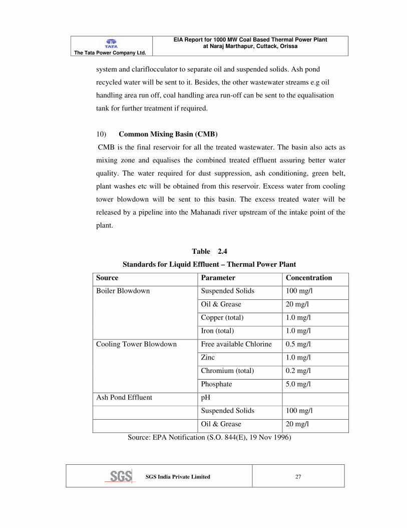
system and clariflocculator to separate oil and suspended solids. Ash pond
recycled water will be sent to it. Besides, the other wastewater streams e.g oil
handling area run off, coal handling area run-off can be sent to the equalisation
tank for further treatment if required.
10) Common Mixing Basin (CMB)
CMB is the final reservoir for all the treated wastewater. The basin also acts as
mixing zone and equalises the combined treated effluent assuring better water
quality. The water required for dust suppression, ash conditioning, green belt,
plant washes etc will be obtained from this reservoir. Excess water from cooling
tower blowdown will be sent to this basin. The excess treated water will be
released by a pipeline into the Mahanadi river upstream of the intake point of the
plant.
Table 2.4
Standards for Liquid Effluent – Thermal Power Plant
Source Parameter Concentration
Suspended Solids 100 mg/l
Oil & Grease 20 mg/l
Copper (total) 1.0 mg/l
Boiler Blowdown
Iron (total) 1.0 mg/l
Free available Chlorine 0.5 mg/l
Zinc 1.0 mg/l
Chromium (total) 0.2 mg/l
Cooling Tower Blowdown
Phosphate 5.0 mg/l
Ash Pond Effluent pH
Suspended Solids 100 mg/l
Oil & Grease 20 mg/l
Source: EPA Notification (S.O. 844(E), 19 Nov 1996)

The Tata Power Company Ltd.
EIA Report for 1000 MW Coal Based Thermal Power Plant at Naraj Marthapur, Cuttack, Orissa
SGS India Private Limited
28
Gaseous Effluent
Emission from Stack
Combustion gases from the boiler emitted through high stack is the main source of
gaseous emission. The emission quality primarily depends upon the quality of the
coal burnt. Since the ash content of the fuel is expected to be in the range of 40%
with occasional variation, a sizeable quantity of fly ash in the form of particulate
matter would be generated. An efficient electrostatic precipitator (separation
along with a properly designed boiler would keep the stack emission of particulate
within acceptable limits. The design of the electrostatic precipitator would ensure
particulates emission level to 100 mg/Nm3, as per CREP norms. The emission
standards as per Environment (Protection) Act Notification are provided in Table
2.5.
Table 2.5
Emission Standards
Unit Capacity Pollutant Emission Limit
210 MW or more Particulate Matter
150 mg/ Nm3
Less than 210 MW Particulate Matter
350 mg/ Nm3
Source: EPA Notification (S.O. 8(E), 3 Jan 1983)
Stack Height Limits
Unit Capacity Stack Height
500 MW and above
275 m
200/210 MW and above to less
than 500 MW
220 m
Source: EPA Notification (G.S.R. 742(E), 30 Aug 1990)
Sulphur di oxide (SO2) emission depends upon the sulfur content of the coal. With
average sulphur content of about 0.5%, SO2 emission per day will be about 163.6
TPD. The concentration will be about 1650 mg/Nm3 There is no prescribed limit
for SO2 emission in Indian standard. However comparing with World Bank
Standard of 2000 mg/Nm3, this is quite reasonable.
The Tata Power Company Ltd.
EIA Report for 1000 MW Coal Based Thermal Power Plant at Naraj Marthapur, Cuttack, Orissa
SGS India Private Limited
29
Nitrogen oxides (NOx) emission is dependent primarily on combustion methods.
There is also no prescribed limit for NOx emission in Indian standard. However
comparing with World Bank Standard of 750 mg/Nm3, The low-NOX burners for
the boilers will be able to achieve this limit.
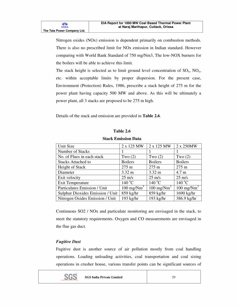
The stack height is selected as to limit ground level concentration of SOx, NOx,
etc. within acceptable limits by proper dispersion. For the present case,
Environment (Protection) Rules, 1986, prescribe a stack height of 275 m for the
power plant having capacity 500 MW and above. As this will be ultimately a
power plant, all 3 stacks are proposed to be 275 m high.
Details of the stack and emission are provided in Table 2.6.
Table 2.6
Stack Emission Data
Unit Size 2 x 125 MW 2 x 125 MW 2 x 250MW
Number of Stacks 1 1 1
No. of Flues in each stack Two (2) Two (2) Two (2)
Stacks Attached to Boilers Boilers Boilers
Height of Stack 275 m 275 m 275 m
Diameter 3.32 m 3.32 m 4.7 m
Exit velocity 25 m/s 25 m/s 25 m/s
Exit Temperature 140 oC 140
oC 140
oC
Particulates Emission / Unit 100 mg/Nm3 100 mg/Nm
3 100 mg/Nm
3
Sulphur Dioxides Emission / Unit 859 kg/hr 859 kg/hr 1690 kg/hr
Nitrogen Oxides Emission / Unit 193 kg/hr 193 kg/hr 386.9 kg/hr
Continuous SO2 / NOx and particulate monitoring are envisaged in the stack, to
meet the statutory requirements. Oxygen and CO measurements are envisaged in
the flue gas duct.
Fugitive Dust
Fugitive dust is another source of air pollution mostly from coal handling
operations. Loading unloading activities, coal transportation and coal sizing
operations in crusher house, various transfer points can be significant sources of

The Tata Power Company Ltd.
EIA Report for 1000 MW Coal Based Thermal Power Plant at Naraj Marthapur, Cuttack, Orissa
SGS India Private Limited
30
fugitive dust. Depending on the suitability of the location, Dust suppression (DS)
or Dust Extraction (DE) will be provided. DS consists of water spraying
arrangements. DE will be placed at transfer points and room ventilation so that the
fugitive dusts are extracted and conveyed pneumatically through a filter system.
Chemical type dust suppression system will be provided for screen house and
junction towers. Plain water type dust suppression system would be provided all
around the stockpile to suppress the dust generated and to keep dust nuisance to
the minimum. Plain water type dust suppression system would be provided for
track hopper and for wagon. The bunker ventilation system would be provided
with bag filters to trap the dust generated while loading coal into bunkers and to
vent out dust free air.
Another source of dust pollution will be dry handling of fly ash. Unloading of ash
from silos and transportation can cause significant dust pollution. Silos will be
provided with water sprays to be operated during unloading. During transportation
fly ash will be taken in covered truck and with water sprayed at the top or closed
truck.
For controlling dust emission from ash pond, after disposing ash for a specific
period (say 6 months or one year), when the ash dump reaches certain height, it
will be covered with a layer of earth. This will be continued till the ash pond is
full with ash.
Solid Waste
Ash
Disposal of ash generated in a coal fired power plant especially having high ash
content coal is generally a problem. With increased awareness and need for
protecting the environment, Ministry of Environment & Forest (MoEF) is
permitting new power stations to be established only with fly ash handling and
disposal in dry form. Keeping this in mind ash utilisation in manufacturing useful
products like fly ash bricks, etc. has been made mandatory by Government of
India’s extraordinary Gazette Notification No.S.O.163(E) dated 14.9.99. and
updated by Gazette Notification MO. S.O. 979 (E) dated 23.08.03
The Tata Power Company Ltd.
EIA Report for 1000 MW Coal Based Thermal Power Plant at Naraj Marthapur, Cuttack, Orissa
SGS India Private Limited
31
TPC has conceived a consolidated ash utilisation plan for the proposed plant. Dry
fly ash will be totally used for cement production, brick manufacturing and some
for mine backfilling. Bottom ash which will initially be dumped in the ash pond
will be excavated and used for landfilling and mine backfilling. Negotiations are
going on with the cement manufacturing units Ambja Cements Ltd and Ultratech
Cements Ltd, for reuse of the fly ash.
A Note on Ash Disposal details the scenario at the end of this chapter
Noise
Noise will be generated in the plant due to running of different machines like the
turbines-generators, pumps, compressor, fans, crushers etc. All general equipment
will be procured which will not exceed noise level of 85 dB(A). However for
some equipment this may not be possible. In those cases the noise generating
equipment will be housed in suitable enclosed places so that the noise outside
would be within acceptable level. Personal working there will be provided with
suitable gears like ear plug etc. for protection.
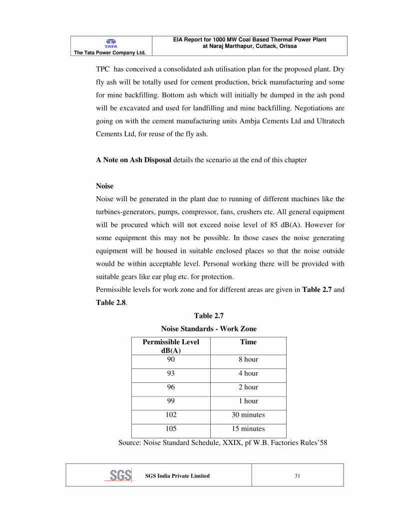
Permissible levels for work zone and for different areas are given in Table 2.7 and
Table 2.8.
Table 2.7
Noise Standards - Work Zone
Permissible Level
dB(A)
Time
90 8 hour
93 4 hour
96 2 hour
99 1 hour
102 30 minutes
105 15 minutes
Source: Noise Standard Schedule, XXIX, pf W.B. Factories Rules’58

The Tata Power Company Ltd.
EIA Report for 1000 MW Coal Based Thermal Power Plant at Naraj Marthapur, Cuttack, Orissa
SGS India Private Limited
32
Table 2.8
Ambient Air Quality Standard in Respect of Noise
Area Code Category of Area Limit in dB(A) Leq
Day Time
Limit in dB(A) Leq*
Night Time
A Industrial area 75 70
B Commercial area 65 55
C Residential area 55 45
D Silence zone 50 50
Note: 1. Day time shall mean from 6.00 am to 9.00 pm
2. Night time shall mean from 9.00 pm to 6.00 am
3. Silence zones is defined as an area comprising not less than 100
meters around hospitals, educational institutions and courts. The
silence zones are declared by the competent authority.
4. Mixed categories of areas may be decided as one of the four above
mentioned categories by the competent authority.
*dB(A) leq denotes time weighted average of the level of sound in decibels on
scale A which is related to human hearing.
Ref: EPA Notification [GSR 1063 (E) 26 December, 1989]
Heat Effluent
Thermal power generation causes emission of large amount of heat as only a
portion of the heat energy is converted to electricity. Heat losses occur through
exhaust gases and through cooling tower.
Heat loss through the stack is only about 8-10% of the total heat input to the
furnace. This is nominal when compared with the capacity of earth as the heat
sink and this would be adequately dispersed with the plume from the high stack.
Moreover, majority of the heat in cooling tower is rejected in the form of
evaporation loss. This does not cause any appreciable thermal pollution to the
surrounding area. It may further be noted that the area has moderate wind speed
and high rainfall.

The Tata Power Company Ltd.
EIA Report for 1000 MW Coal Based Thermal Power Plant at Naraj Marthapur, Cuttack, Orissa
SGS India Private Limited
33
Hazardous Waste
Coal based power generation process does not generate any hazardous waste as
defined in rules [Ref. Hazardous Waste (Management and Handling) Amendment
Rules, 2000].
However besides the main process, some of the utility activities can generate
some hazardous wastes such as
a) Oily sludge from separators
b) Used Oil
c) Used batteries
Oily sludge will be separated and stored in lined pits. Used oil and the batteries
will be sold to the authorized dealers.
Note on Ash Disposal
Problems of disposal of ash, both bottom ash and fly ash, from the solid fossil
fuel-fired boilers are attracting attention of environmentalists as well as
technologists all over the globe. The concept of ash disposal generally adopted in
almost all the thermal power stations up to the recent past was to dispose the
mixture of fly and bottom ash in (lean) slurry form which were impounded in low
lying areas called ‘ash pond’. The mixtures of fly ash and bottom ash, due to
different physical and chemical properties were thought to be ineffective for
commercial exploitation. Considerable research and development work
undertaken during the past two to three decades throughout the world has opened
various avenues of commercial utilization of fly ash.
Fly ash is an amorphous ferro-alumina silicate compound of spherical crystalline
shape with particle sizes ranging between 2 to 50 micron. It varies from light to
dark gray in colour with specific gravity lying between 1.9 to 2.3 and the bulk
density of loose dry fly ash is around 800 Kg/m3.
Fly ash has good pozzolonic property, good flowability and low permeability,
which facilitate myriad utilization of fly ash. Ash generated from the station
would have sizeable quantum of inert oxides and carbonates of silica, alumina,
The Tata Power Company Ltd.
EIA Report for 1000 MW Coal Based Thermal Power Plant at Naraj Marthapur, Cuttack, Orissa
SGS India Private Limited
34
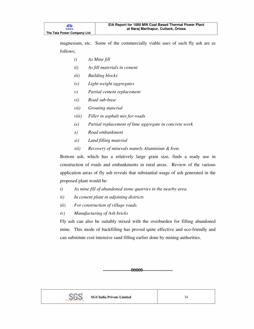
magnesium, etc. Some of the commercially viable uses of such fly ash are as
follows;
i) As Mine fill
ii) As fill materials in cement
iii) Building blocks
iv) Light-weight aggregates
v) Partial cement replacement
vi) Road sub-base
vii) Grouting material
viii) Filler in asphalt mix for roads
ix) Partial replacement of lime aggregate in concrete work
x) Road embankment
xi) Land filling material
xii) Recovery of minerals namely Aluminium & Iron.
Bottom ash, which has a relatively large grain size, finds a ready use in
construction of roads and embankments in rural areas. Review of the various
application areas of fly ash reveals that substantial usage of ash generated in the
proposed plant would be:
i) As mine fill of abandoned stone quarries in the nearby area.
ii) In cement plant in adjoining districts
iii) For construction of village roads.
iv) Manufacturing of Ash bricks
Fly ash can also be suitably mixed with the overburden for filling abandoned
mine. This mode of backfilling has proved quite effective and eco-friendly and
can substitute cost intensive sand filling earlier done by mining authorities.
------------------00000-------------------