Ch 1 - Intermediate rigging · stretcher, oar and rigger for individual athletes. 3.0 A SYSTEMATIC...
12
Intermediate Rigging Editors: Ted Daigneault (CAN), Matt Smith (USA), Thor S. Nilsen (NOR) 1
Transcript of Ch 1 - Intermediate rigging · stretcher, oar and rigger for individual athletes. 3.0 A SYSTEMATIC...

Intermediate RiggingEditors: Ted Daigneault (CAN), Matt Smith (USA), Thor S. Nilsen (NOR)
1
10
1.0 INTRODUCTION
The FISA CDP Level I course in rigging, titled BASIC RIGGING,introduced the terminology of the principle parts of the boat andequipment as well as the basic adjustments and the tools neces-sary to make those adjustments. The course also emphasized thenecessity of regular equipment maintenance and recommendedmeasurements for club level boats.
This course will expand on those topics and, since the construc-tion of modern boats allows the possibility of individualized rig-ging, emphasize adjustments that will assist the individual ath-lete. At the end of this booklet, there is a Table of RecommendedMeasurements for national level boats for reference. By the endof this course, you will be able to make proper adjustments tothe equipment for a national level athlete.
Since the mid-1980s when the FISA Coaching DevelopmentProgram began, composite materials have essentially replacedwood in the construction of oars and sculls as well as boatsexcepting the structural frame of boats. The detailed care andmaintenance of equipment constructed with composite materialsis different than when constructed with wood, but this informa-tion in beyond the scope of this program and is available fromothers sources either within FISA or directly from manufacturers.Though the mechanical principles have, of course, remainunchanged, there has been a change in the length of the oar orscull due to a dramatic alteration during the 1990s in the sizeand shape of the blade. This alteration has increased the hold-ing power of the blade thus necessitating a shorter outboard dis-tance otherwise the rower would not be able to draw the oar orscull through the water due to the increased load.
The FISA Coaching Development Program has been active overthe last number of years in collecting wooden material eitheroars or sculls as well as boats and sending it to new FISA mem-ber or developing countries. By reason of this activity, this chap-ter remains relevant and the charts remain unchanged. Even so,it is to be noted that, in effect, only the outboard distance meas-urements have been affected (and, of course, the total length ofthe oar or scull) and the other measurements remain unaffected.
11
1. INTERMEDIATE RIGGING
12
The process must be systematic by requiring a written record ofthe reason for the adjustment and the measurements.
In the event that the adjustment does not achieve the desiredresult, a further change may be made at the same or anotherlocation. It is advisable that only one small adjustment (between0.5 and 1.0 cm) be made for each attempt to achieve thedesired result. This procedure will allow an opportunity for theathlete to adapt to the change and for a proper assessment ofthe effect of each adjustment.
It should be noted that the initial adjustments to the boat andequipment will have been established within the guidelines pre-sented in either BASIC RIGGING or this booklet (or, of course,some other suitable source). These adjustments and subsequentalterations will have been recorded by you or your athlete in arigging chart.
The rigging chart will provide a convenient list to set, check andduplicate the measurements, particularly after boat transportation,and will provide a convenient summary of alterations. A samplerigging chart is provided for your assistance in Appendix A.
4.0 BOATS AND EQUIPMENT
The basic terminology used in sculling and sweep rowing hasbeen presented in BASIC RIGGING. Since this section will onlyprovide further information and not review Level I, it is recom-mended that BASIC RIGGING be reviewed prior to proceedingwith this section.
4.1 The Boat
The size and shape of the hull of the boat is generally deter-mined by the manufacturer. Although a deeper and narrower hullcreates less resistance to its movement in water than a flat bot-tomed boat, it is not as stable and, therefore, is more difficult foryoung and beginning athletes to row.
The depth of immersion of any specific hull is also established by
13
1. INTERMEDIATE RIGGING
Suggestions for changes in the affected outboard measurementsdue to the 'big blade' were presented in Level I, but are notrepeated here.
2.0 THE PURPOSE OF RIGGING
It was stated in BASIC RIGGING that rowing is a sport thatrequires concerted motion between the athlete and the boat.Further, it is clear that rowing requires well maintained boats andequipment and learning proper technique requires that theequipment be properly adjusted.
"A properly rigged boat may not necessarily win the race foryou, but a poorly rigged boat will impede the performance ofyour crew and cause technique problems that are difficult to cor-rect": the CARA Coaching Manuals.
The primary purpose of rigging is to provide the athlete with acomfortable work position from which the most effective powerapplication to the boat by the oar can be performed. Althoughrigging partly determines technique, it should permit the execu-tion of a technique with natural movements. This will enable theathlete to effectively apply power through an oar with a bladefully covered and traveling on a horizontal plane through thedrive phase of the stroke cycle.
In the formation of a crew, the primary purpose of riggingbecomes the development of a uniform power application whichmay result in different adjustments and measurements of the foot-stretcher, oar and rigger for individual athletes.
3.0 A SYSTEMATIC PLAN / A RIGGING CHART
The purpose of rigging is achieved by adjusting the boat andequipment to optimize the movement of the athlete and, in theformation of a crew, to accommodate athletes of different size,strength and range of movement. The determination of an opti-mum rig for an individual or crew is a trial and error processusing the experience of the coach and the aid of a stop watch.
14
4.2 The Oar *)
*) In this part oars and sculls with the Macon blade made from wood or,perhaps, composite materials are the focus, since they are still used inmany developing countries. For many years composite oars or scullshave dominated the market. These should be delivered with fixed pointof gravity and with varying stiffness — stiff, medium or soft — depend-ing on the manufacturer. Some manufacturers also deliver oars and scullswith adjustable handles.
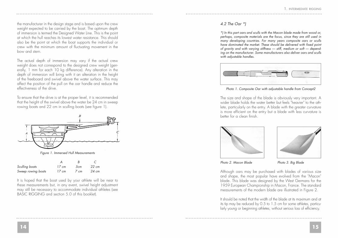
Photo 1. Composite Oar with adjustable handle from Concept2
The size and shape of the blade is obviously very important. Awider blade holds the water better but feels "heavier" to the ath-lete, particularly on the entry. A blade with the greater curvatureis more efficient on the entry but a blade with less curvature isbetter for a clean finish.
Photo 2. Macon Blade Photo 3. Big Blade
Although oars may be purchased with blades of various sizeand shape, the most popular have evolved from the "Macon"blade. This blade was designed by the West Germans for the1959 European Championship in Macon, France. The standardmeasurements of the modern blade are illustrated in Figure 2.
It should be noted that the width of the blade at its maximum and atits tip may be reduced by 0.5 to 1.5 cm for some athletes, particu-larly young or beginning athletes, without serious loss of efficiency.
15
1. INTERMEDIATE RIGGING
the manufacturer in the design stage and is based upon the crewweight expected to be carried by the boat. The optimum depthof immersion is termed the Designed Water Line. This is the pointat which the hull reaches its lowest water resistance. This shouldalso be the point at which the boat supports the individual orcrew with the minimum amount of fluctuating movement in thebow and stern.
The actual depth of immersion may vary if the actual crewweight does not correspond to the designed crew weight (gen-erally, 1 mm for each 10 kg difference). Any alteration in thedepth of immersion will bring with it an alteration in the heightof the freeboard and swivel above the water surface. This mayaffect the position of the pull on the oar handle and reduce theeffectiveness of the drive.
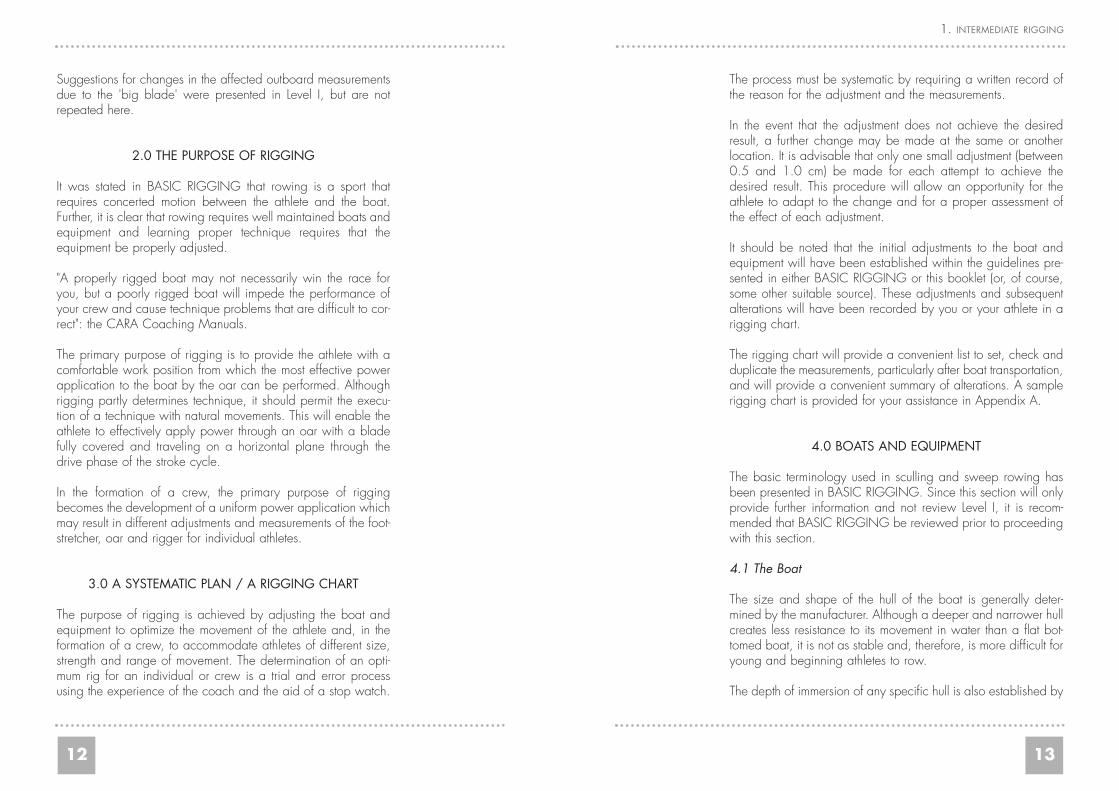
To ensure that the drive is at the proper level, it is recommendedthat the height of the swivel above the water be 24 cm in sweeprowing boats and 22 cm in sculling boats (see figure 1).
Figure 1. Immersed Hull Measurements
A B CSculling boats 17 cm 5cm 22 cmSweep rowing boats 17 cm 7 cm 24 cm
It is hoped that the boat used by your athlete will be near tothese measurements but, in any event, swivel height adjustmentmay still be necessary to accommodate individual athletes (seeBASIC RIGGING and section 5.0 of this booklet).
16
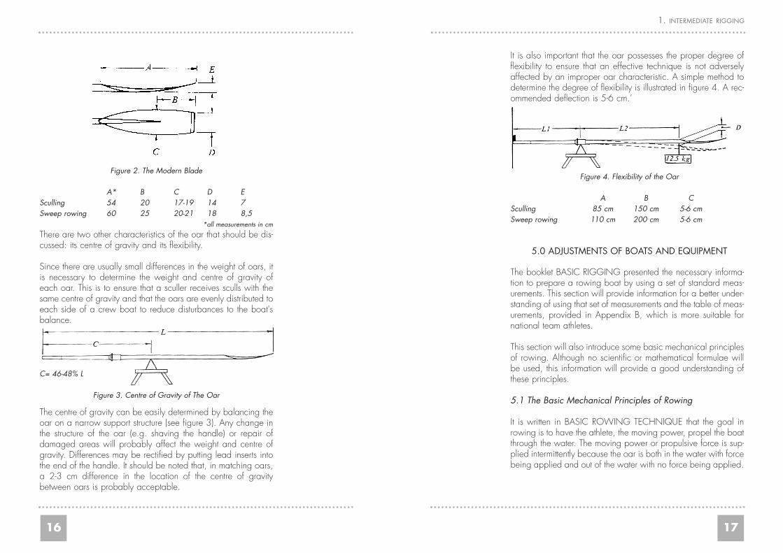
It is also important that the oar possesses the proper degree offlexibility to ensure that an effective technique is not adverselyaffected by an improper oar characteristic. A simple method todetermine the degree of flexibility is illustrated in figure 4. A rec-ommended deflection is 5-6 cm.’
Figure 4. Flexibility of the Oar
A B CSculling 85 cm 150 cm 5-6 cmSweep rowing 110 cm 200 cm 5-6 cm
5.0 ADJUSTMENTS OF BOATS AND EQUIPMENT
The booklet BASIC RIGGING presented the necessary informa-tion to prepare a rowing boat by using a set of standard meas-urements. This section will provide information for a better under-standing of using that set of measurements and the table of meas-urements, provided in Appendix B, which is more suitable fornational team athletes.
This section will also introduce some basic mechanical principlesof rowing. Although no scientific or mathematical formulae willbe used, this information will provide a good understanding ofthese principles.
5.1 The Basic Mechanical Principles of Rowing
It is written in BASIC ROWING TECHNIQUE that the goal inrowing is to have the athlete, the moving power, propel the boatthrough the water. The moving power or propulsive force is sup-plied intermittently because the oar is both in the water with forcebeing applied and out of the water with no force being applied.
17
1. INTERMEDIATE RIGGING
Figure 2. The Modern Blade
A* B C D ESculling 54 20 17-19 14 7Sweep rowing 60 25 20-21 18 8,5
*all measurements in cm
There are two other characteristics of the oar that should be dis-cussed: its centre of gravity and its flexibility.
Since there are usually small differences in the weight of oars, itis necessary to determine the weight and centre of gravity ofeach oar. This is to ensure that a sculler receives sculls with thesame centre of gravity and that the oars are evenly distributed toeach side of a crew boat to reduce disturbances to the boat'sbalance.
C= 46-48% L
Figure 3. Centre of Gravity of The Oar
The centre of gravity can be easily determined by balancing theoar on a narrow support structure (see figure 3). Any change inthe structure of the oar (e.g. shaving the handle) or repair ofdamaged areas will probably affect the weight and centre ofgravity. Differences may be rectified by putting lead inserts intothe end of the handle. It should be noted that, in matching oars,a 2-3 cm difference in the location of the centre of gravitybetween oars is probably acceptable.
18
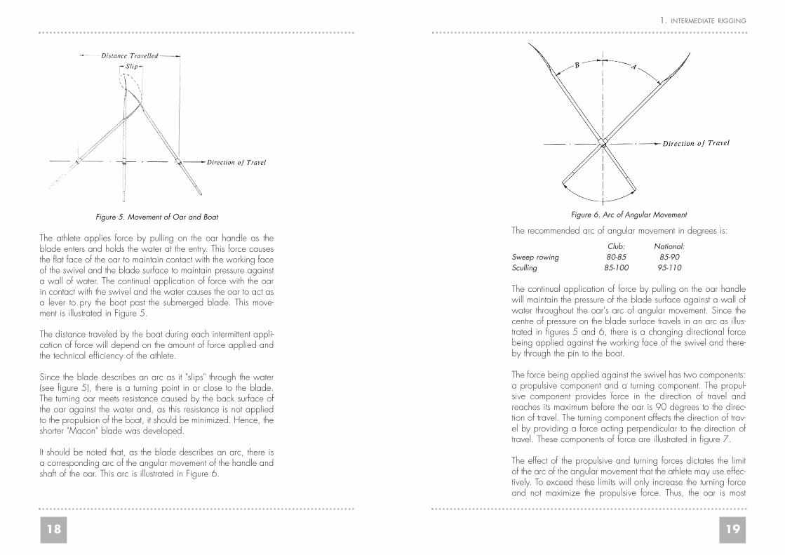
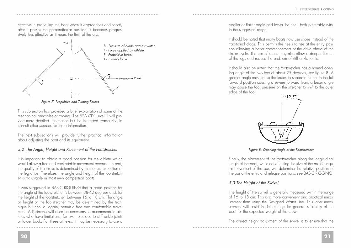
Figure 6. Arc of Angular Movement
The recommended arc of angular movement in degrees is:
Club: National:Sweep rowing 80-85 85-90Sculling 85-100 95-110
The continual application of force by pulling on the oar handlewill maintain the pressure of the blade surface against a wall ofwater throughout the oar's arc of angular movement. Since thecentre of pressure on the blade surface travels in an arc as illus-trated in figures 5 and 6, there is a changing directional forcebeing applied against the working face of the swivel and there-by through the pin to the boat.
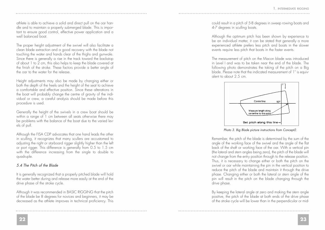
The force being applied against the swivel has two components:a propulsive component and a turning component. The propul-sive component provides force in the direction of travel andreaches its maximum before the oar is 90 degrees to the direc-tion of travel. The turning component affects the direction of trav-el by providing a force acting perpendicular to the direction oftravel. These components of force are illustrated in figure 7.
The effect of the propulsive and turning forces dictates the limitof the arc of the angular movement that the athlete may use effec-tively. To exceed these limits will only increase the turning forceand not maximize the propulsive force. Thus, the oar is most
19
1. INTERMEDIATE RIGGING
Figure 5. Movement of Oar and Boat
The athlete applies force by pulling on the oar handle as theblade enters and holds the water at the entry. This force causesthe flat face of the oar to maintain contact with the working faceof the swivel and the blade surface to maintain pressure againsta wall of water. The continual application of force with the oarin contact with the swivel and the water causes the oar to act asa lever to pry the boat past the submerged blade. This move-ment is illustrated in Figure 5.
The distance traveled by the boat during each intermittent appli-cation of force will depend on the amount of force applied andthe technical efficiency of the athlete.
Since the blade describes an arc as it "slips" through the water(see figure 5), there is a turning point in or close to the blade.The turning oar meets resistance caused by the back surface ofthe oar against the water and, as this resistance is not appliedto the propulsion of the boat, it should be minimized. Hence, theshorter "Macon" blade was developed.
It should be noted that, as the blade describes an arc, there isa corresponding arc of the angular movement of the handle andshaft of the oar. This arc is illustrated in Figure 6.
20
smaller or flatter angle and lower the heel, both preferably with-in the suggested range.
It should be noted that many boats now use shoes instead of thetraditional clogs. This permits the heels to rise at the entry posi-tion allowing a better commencement of the drive phase of thestroke cycle. The use of shoes may also allow a deeper flexionof the legs and reduce the problem of stiff ankle joints.
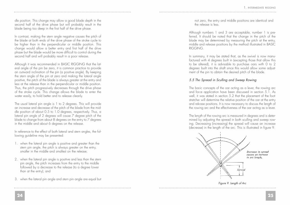
It should also be noted that the footstretcher has a normal open-ing angle of the two feet of about 25 degrees, see figure 8. Agreater angle may cause the knees to separate further in the fullforward position causing a severe forward lean; a lesser anglemay cause the foot pressure on the stretcher to shift to the outeredge of the foot.
Figure 8. Opening Angle of the Footstretcher
Finally, the placement of the footstretcher along the longitudinallength of the boat, while not affecting the size of the arc of angu-lar movement of the oar, will determine the relative position ofthe oar at the entry and release positions, see BASIC RIGGING.
5.3 The Height of the Swivel
The height of the swivel is generally measured within the rangeof 16 to 18 cm. This is a more convenient and practical meas-urement than using the Designed Water Line. This latter meas-urement will assist in determining the general suitability of theboat for the expected weight of the crew.
The correct height adjustment of the swivel is to ensure that the
21
1. INTERMEDIATE RIGGING
effective in propelling the boat when it approaches and shortlyafter it passes the perpendicular position; it becomes progres-sively less effective as it nears the limit of the arc.
Figure 7. Propulsive and Turning Forces
This sub-section has provided a brief explanation of some of themechanical principles of rowing. The FISA CDP Level III will pro-vide more detailed information but the interested reader shouldconsult other sources for more information.
The next sub-sections will provide further practical informationabout adjusting the boat and its equipment.
5.2 The Angle, Height and Placement of the Footstretcher
It is important to obtain a good position for the athlete whichwould allow a free and comfortable movement because, in part,the quality of the stroke is determined by the correct execution ofthe leg drive. Therefore, the angle and height of the footstretch-er is adjustable in most new competition boats.
It was suggested in BASIC RIGGING that a good position forthe angle of the footstretcher is between 38-42 degrees and, forthe height of the footstretcher, between 15 to 18 cm. The angleor height of the footstretcher may be determined by the tech-nique but should, again, permit a free and comfortable move-ment. Adjustments will often be necessary to accommodate ath-letes who have limitations, for example, due to stiff ankle jointsor lower back. For these athletes, it may be necessary to use a
B - Pressure of blade against water.F - Force applied by athlete.P - Propulsive force.T - Turning force.
22
could result in a pitch of 5-8 degrees in sweep rowing boats and4-7 degrees in sculling boats.
Although the optimum pitch has been shown by experience tobe an individual matter, it can be stated that generally a moreexperienced athlete prefers less pitch and boats in the slowerevents require less pitch that boats in the faster events.
The measurement of pitch on the Macon blade was introducedin Level I and was to be taken near the end of the blade. Thefollowing photo demonstrates the taking of the pitch on a Bigblade. Please note that the indicated measurement of 1" is equiv-alent to about 2.5 cm.
Photo 3. Big Blade picture instructions from Concept2.
Remember, the pitch of the blade is determined by the sum of theangle of the working face of the swivel and the angle of the flatback of the shaft or working face of the oar. With a vertical pin(the lateral and stern angles being zero), the pitch of the blade willnot change from the entry position through to the release position.Thus, it is necessary to change either or both the pitch on theswivel or oar while maintaining the pin in the vertical position toreduce the pitch of the blade and maintain it through the drivephase. Changing either or both the lateral or stern angle of thepin will result in the pitch on the blade changing through thedrive phase.
By keeping the lateral angle at zero and making the stern anglepositive, the pitch of the blade at both ends of the drive phaseof the stroke cycle will be lower than in the perpendicular or mid-
23
1. INTERMEDIATE RIGGING
athlete is able to achieve a solid and direct pull on the oar han-dle and to maintain a properly submerged blade. This is impor-tant to ensure good control, effective power application and awell balanced boat.
The proper height adjustment of the swivel will also facilitate aclean blade extraction and a good recovery with the blade nottouching the water and hands clear of the thighs and gunwale.Since there is generally a rise in the track toward the backstopof about 1 to 2 cm, this also helps to keep the blade covered atthe finish of the stroke. These factors provide a better angle ofthe oar to the water for the release.
Height adjustments may also be made by changing either orboth the depth of the heels and the height of the seat to achievea comfortable and effective position. Since these alterations inthe boat will probably change the centre of gravity of the indi-vidual or crew, a careful analysis should be made before thisprocedure is used.
Generally the height of the swivels in a crew boat should bewithin a range of 1 cm between all seats otherwise there maybe problems with the balance of the boat due to the varied lev-els of pull.
Although the FISA CDP advocates that one hand leads the otherin sculling, it recognizes that many scullers are accustomed toadjusting the right or starboard rigger slightly higher than the leftor port rigger. This difference is generally from 0.5 to 1.5 cmwith the difference increasing from the single to double toquadruple.
5.4 The Pitch of the Blade
It is generally recognized that a properly pitched blade will holdthe water better during and release more easily at the end of thedrive phase of the stroke cycle.
Although it was recommended in BASIC RIGGING that the pitchof the blade be 8 degrees for novices and beginners, it may bedecreased as the athlete improves in technical proficiency. This
24
not zero, the entry and middle positions are identical and the release is less.
Although numbers 1 and 3 are acceptable, number 1 is pre-ferred. It should be noted that the change in the pitch of theblade may be determined by measuring the pitch at the entry,middle and release positions by the method illustrated in BASICRIGGING.
In summary, it may be stated that, as the swivel is now manu-factured with 4 degrees built in (excepting those that allow thisto be altered), it is advisable to purchase oars with 0 to 2degrees built into the shaft since this would allow some adjust-ment of the pin to obtain the desired pitch of the blade.
5.5 The Spread in Sculling and Sweep Rowing
The basic concepts of the oar acting as a lever, the rowing arcand force application have been discussed in section 5.1. Aswell, it was stated in section 5.2 that the placement of the foot-stretcher will determine the relative position of the oar at the entryand release positions. It is now necessary to discuss the length ofthe rowing arc and the effectiveness of the oar acting as a lever.
The length of the rowing arc is measured in degrees and is deter-mined by adjusting the spread in both sculling and sweep row-ing. Decreasing (increasing) the spread will cause an increase(decrease) in the length of the arc. This is illustrated in figure 9.
Figure 9. Length of Arc
25
1. INTERMEDIATE RIGGING
dle position. This change may allow a good blade depth in thesecond half of the drive phase but will probably result in theblade being too deep in the first half of the drive phase.
In contrast, making the stern angle negative causes the pitch ofthe blade at both ends of the drive phase of the stroke cycle tobe higher than in the perpendicular or middle position. Thischange would allow a better entry and first half of the drivephase but the blade would be more difficult to control during thesecond half and will probably result in a poor release.
Although it was recommended in BASIC RIGGING that the lat-eral angle of the pin be zero, it is common practice to providean outward inclination of the pin (a positive angle). By keepingthe stern angle of the pin at zero and making the lateral anglepositive, the pitch of the blade is always greater at the entry andless at the release than in the perpendicular or middle position.Thus, the pitch progressively decreases through the drive phaseof the stroke cycle. This change allows the blade to enter thewater easily, to hold better and to release cleanly.
The usual lateral pin angle is 1 to 2 degrees. This will providean increase and decrease of the pitch of the blade from the mid-dle position of about 0.5 to 1.0 degrees, respectively. Thus, alateral pin angle of 2 degrees will cause 7 degree pitch of theblade to change from about 8 degrees on the entry to 7 degreesin the middle and about 6 degrees on the release.
In reference to the effect of both lateral and stern angles, the fol-lowing guideline may be presented:
1. when the lateral pin angle is positive and greater than the stern pin angle, the pitch is always greater on the entry, smaller in the middle and smallest on the release;
2. when the lateral pin angle is positive and less than the sternpin angle, the pitch increases from the entry to the middle followed by a decrease to the release (to a degree lower than at the entry); and
3. when the lateral pin angle and stern pin angle are equal but

by increasing the ratio will impose a greater load on the athlete.This load increase is due to the increase in the speed of move-ment of the blade that would be necessary to work through theincreased length of arc and maintain the stroke rate.
Ideally, it is necessary that the oars in a crew boat remain par-allel through the stroke cycle and the ratio is constant for allseats. This may necessitate adjusting the spread for an individ-ual to achieve the desired length of arc and providing an oar ofa length that maintains the same ratio within the crew. Thus, increw boats, individuals may row with different spread andlength of oars.
The inboard distance must be appropriate to permit the athletesnatural path of movement throughout the stroke cycle. As sug-gested in BASIC RIGGING, the inboard distance will be about30-32 cm and 9-11 cm greater than the spread at each riggerfor sweep rowing and sculling oars, respectively.
This situation of an individual adjustment is obviously only appli-cable to national crews as it necessitates the availability of vari-ous lengths of oars.
In the more common situation of using a set of oars of equallength, an attempt is made to achieve the uniformity of arc lengthand load ratio by:
1. Rigging the boat using an acceptable spread (or narrow range of spread among the individuals of the crew) based on the length of the oar and desired loading.
2. Adjusting the position of the oar button to provide the appropriate outboard distance based on the desired loading and the natural movement path (overlap).
An example may be provided by considering men’s 4- that hasone man who rows with a longer arc of angular movement. Anattempt could be made to decrease this individual's arc byincreasing the spread while maintaining about the same loadand still providing a natural path of movement (with overlap of30-32). Thus,
27
1. INTERMEDIATE RIGGING
26
The actual length of arc chosen (see guidelines in section 5.1)for an individual will depend on the fitness, range of movementor technical proficiency of the individual. An improvement inthese factors will allow the use of a longer arc (within the limitssuggested under the discussion about propulsive and turningforces).
The effectiveness of the oar acting as a lever or, in other words,the load applied by the athlete during the drive phase of thestroke cycle depends on:
1. the spread, and2. the outboard distance of the oar.
The important measure of the load is the effect of the centre ofthe pull on the handle against the pin and the centre of pressureon the blade. The distance from the centre of the pull to the pinis essentially the spread. The distance from the pin to the centreof pressure may be measured to this pressure point or to the endof the blade. The latter measurement to the end of the blade isthe outboard distance and is perhaps not technically as accurateas measuring to the pressure point but is more convenient andpractical.
Therefore, the effectiveness of the oar may be expressed byusing these variables in the ratio:
Outboard distanceSpread
Thus, using the figures provided in Appendix B:
SPREAD* OUTBOARD INBOARD LENGTH RATIO
Pair with: 90 265 120 385 2,94Eight: 80 275 110 385 3,44
*all measurements in cm
we could have the range of 2.94 to 3.44. The greater the ratio,the greater the effective load applied by the athlete.
For a given spread, increasing the outboard distance and there-

SPREAD* OUTBOARD INBOARD LENGTH RATIO OVERLAP
Pair with: 85,0 267,0 115,0 382 3,14 32Eight: 85,5 267,5 114,5 382 3,13 31
*all measurements in cm
Since the inboard distance allows a range of 30-32 cm and 9-11 cm for a sweep rowing and sculling oar, respectively, exactaccommodation can be made for the crew or an individual byadjusting the button on the oar depending on fitness, range ofmovement or weather conditions. This accommodation will, ofcourse, change the outboard distance and thereby the load car-ried by the athlete.
Finally, a comment should be made about another factor thataffects the length of arc and the effectiveness of the oar. This fac-tor is the height of the arm pull during the drive phase.Essentially, a higher arm pull will result in an increase in both thelength of arc and the effectiveness of the oar. This is illustrated infigure 10.
Figure 10. Arm Pull
6.0 SUMMARY
This booklet has attempted to provide more exact information inregard to the making of the correct adjustments to the equipmentfor a national level athlete.
It should be noted that, before correcting technique, it is advis-able to first check the adjustment of the equipment. It is alsoadvisable to exercise caution in the range of measurements usedby following the guidelines presented either in this booklet orBASIC RIGGING and not be confused by the variations andextremes practiced by some coaches and experienced athletes.
7.0 APPENDICES
7.1 Appendix A - Table of Recommended Measurements
Club level - “Big Blade” - all measurements in cm.
MEN:
2- 87 257 117 374 302+ 88 256 118 374 304- 85 259 115 374 304+ 86 258 116 374 308+ 84 260 114 374 30
WOMEN:
2- 86 256 116 372 304- 85 257 115 372 308+ 84 258 114 372 30
29
1. INTERMEDIATE RIGGING
28

31
1. INTERMEDIATE RIGGING
30
NAME:
DATE:
BOAT:TypeDesign wt.
OAR:- make- length- pitch
BLADE- width- tip- length
ADJUSTMENTS:Track lengthFootstretcher- angle- height- placement- openingSwivel- pitch- heightSpreadOutboardInboardRatioPitch/BaldePin Angle- forward- lateral
7.2 Appendix B - Rigging Chart