CFD SIMULATION OF TWO-PHASE FLOW IN A VENTURI SCRUBBER...
10
IV Journeys in Multiphase Flows (JEM 2017) March 27-31, 2017, São Paulo, SP, Brazil Copyright © 2017 by ABCM Paper ID: JEM-2017-0013 CFD SIMULATION OF TWO-PHASE FLOW IN A VENTURI SCRUBBER: VALIDATION AND COMPARISON OF SECONDARY ATOMIZATION MODELS (SINGLE BLANK LINE SIZE 14) Alexander Ariyoshi Zerwas University of São Paulo, Dep. Chemical Engineering [email protected] (S José Luís de Paiva University of São Paulo, Dep. Chemical Engineering [email protected] (S 10) Abstract. In order to study the two-phase flow dynamics inside an industrial Venturi scrubber, the present work compares numerical simulations employing the standard k-ε turbulence model and the Eulerian-Lagrangian method with different droplet breakup models, as implemented in ANSYS CFX 15.0, with experimental data. It is also compared the influence of liquid injection in the droplet dispersion inside the Venturi scrubber, which was achieved by comparing injecting droplets with the same diameter and injecting droplets with a size-distribution (Rosin-Rammler). A better liquid dispersion was achieved using CAB model. (single space line, size 10) Keywords: computational fluid dynamics (CFD), model validation, secondary atomization, multiphase flow modeling ( 1. INTRODUCTION ( Venturi scrubbers are widely used in industry as gas cleaning devices to control pollution emissions, due to their high collection efficiency, simple structure and implementation, according to Ahmadvand and Talaie (2010). This type of scrubber consists generally of three segments: convergent section, throat and divergent section. In the convergent section, gas flow accelerates due to a reduction in cross-section area, hence reducing static pressure, occurring the opposite in the divergent section, in which gas velocity is reduced due to an increase in cross-section area and pressure regain occurs. In those equipment, the injection of liquid occurs in convergent or throat sections and production of droplets of liquid are achieved by a jet atomization or spray injection. The high relative velocity between the gas and liquid phases causes the jet breakup, whilst a pressure difference in a spray nozzle causes the liquid dispersion. Liquid droplets produced collect contaminants in the gas flow as they travel through the equipment’s length by three main mechanisms, known as, inertial impaction, interception and diffusion, as explained in Heumann (1997). This contaminant collection efficiency is largely affected by droplet size, relative velocity between phases, liquid atomization, liquid injection method, droplet dispersion in cross-section area and others, as noted by Ali et al. (2012). Since interaction between liquid droplets and gas phase is a complex problem, the prediction of multiphase dynamic behavior in industrial equipment with computational fluid dynamics (CFD) has been gaining highlights, as noted by Guerra et al. (2012). However, these numerical simulations need to be checked against experimental data in order to verify their feasibility. In order to study the two-phase flow dynamics inside an industrial Venturi scrubber, the present compares CFD simulations employing standard k-ε turbulence model and Eulerian-Lagrangian method, as implemented in ANSYS CFX 15.0 (Ansys, 2013), with experimental data obtained by Silva (2008) inside a plant pilot size Venturi scrubber and empirical correlations (Hsiang and Faeth, 1992; Wert, 1995). It is also compared the influence of liquid injection in the droplet dispersion inside the Venturi scrubber, which was achieved by comparing injecting droplets with the same diameter and injecting droplets with a size-distribution (Rosin-Rammler), with parameters given by Gonçalves et al. (2003). 2. LITERATURE REVIEW Venturi scrubbers have been extensively studied in literature in order to model and understand their multiphase flow, according to Silva (2008). One important design parameter is pressure loss through the equipment and so Boll (1973) developed a one-dimensional momentum balance equation in order to predict pressure drop in a Venturi scrubber. The proposed model considered pressure loss due to wall friction and momentum exchange due to acceleration of liquid droplets and gas acceleration. Viswanathan et al. (1985) predicted pressure drop inside a Venturi scrubber as an annular-flow, with momentum transfer similar to approach used by Boll (1973). For more information
Transcript of CFD SIMULATION OF TWO-PHASE FLOW IN A VENTURI SCRUBBER...

IV Journeys in Multiphase Flows (JEM 2017) March 27-31, 2017, São Paulo, SP, Brazil
Copyright © 2017 by ABCM
Paper ID: JEM-2017-0013
CFD SIMULATION OF TWO-PHASE FLOW IN A VENTURI SCRUBBER:
VALIDATION AND COMPARISON OF SECONDARY ATOMIZATION
MODELS
(SINGLE BLANK LINE SIZE 14) Alexander Ariyoshi Zerwas University of São Paulo, Dep. Chemical Engineering
(S
José Luís de Paiva University of São Paulo, Dep. Chemical Engineering
(S 10)
Abstract. In order to study the two-phase flow dynamics inside an industrial Venturi scrubber, the present work
compares numerical simulations employing the standard k-ε turbulence model and the Eulerian-Lagrangian method
with different droplet breakup models, as implemented in ANSYS CFX 15.0, with experimental data. It is also
compared the influence of liquid injection in the droplet dispersion inside the Venturi scrubber, which was achieved by
comparing injecting droplets with the same diameter and injecting droplets with a size-distribution (Rosin-Rammler).
A better liquid dispersion was achieved using CAB model.
(single space line, size 10)
Keywords: computational fluid dynamics (CFD), model validation, secondary atomization, multiphase flow modeling
(
1. INTRODUCTION
(
Venturi scrubbers are widely used in industry as gas cleaning devices to control pollution emissions, due to their
high collection efficiency, simple structure and implementation, according to Ahmadvand and Talaie (2010). This type
of scrubber consists generally of three segments: convergent section, throat and divergent section. In the convergent
section, gas flow accelerates due to a reduction in cross-section area, hence reducing static pressure, occurring the
opposite in the divergent section, in which gas velocity is reduced due to an increase in cross-section area and pressure
regain occurs.
In those equipment, the injection of liquid occurs in convergent or throat sections and production of droplets of
liquid are achieved by a jet atomization or spray injection. The high relative velocity between the gas and liquid phases
causes the jet breakup, whilst a pressure difference in a spray nozzle causes the liquid dispersion. Liquid droplets
produced collect contaminants in the gas flow as they travel through the equipment’s length by three main mechanisms,
known as, inertial impaction, interception and diffusion, as explained in Heumann (1997). This contaminant collection
efficiency is largely affected by droplet size, relative velocity between phases, liquid atomization, liquid injection
method, droplet dispersion in cross-section area and others, as noted by Ali et al. (2012).
Since interaction between liquid droplets and gas phase is a complex problem, the prediction of multiphase dynamic
behavior in industrial equipment with computational fluid dynamics (CFD) has been gaining highlights, as noted by
Guerra et al. (2012). However, these numerical simulations need to be checked against experimental data in order to
verify their feasibility.
In order to study the two-phase flow dynamics inside an industrial Venturi scrubber, the present compares CFD
simulations employing standard k-ε turbulence model and Eulerian-Lagrangian method, as implemented in ANSYS
CFX 15.0 (Ansys, 2013), with experimental data obtained by Silva (2008) inside a plant pilot size Venturi scrubber and
empirical correlations (Hsiang and Faeth, 1992; Wert, 1995). It is also compared the influence of liquid injection in the
droplet dispersion inside the Venturi scrubber, which was achieved by comparing injecting droplets with the same
diameter and injecting droplets with a size-distribution (Rosin-Rammler), with parameters given by Gonçalves et al.
(2003).
2. LITERATURE REVIEW
Venturi scrubbers have been extensively studied in literature in order to model and understand their multiphase
flow, according to Silva (2008). One important design parameter is pressure loss through the equipment and so Boll
(1973) developed a one-dimensional momentum balance equation in order to predict pressure drop in a Venturi
scrubber. The proposed model considered pressure loss due to wall friction and momentum exchange due to
acceleration of liquid droplets and gas acceleration. Viswanathan et al. (1985) predicted pressure drop inside a Venturi
scrubber as an annular-flow, with momentum transfer similar to approach used by Boll (1973). For more information

Zerwas, A.A. and Paiva, J.L. CFD simulation of two-phase flow in a Venturi scrubber: Validation and comparison of secondary atomization models
about pressure loss equations for Venturi scrubbers, it is recommended the work of Gonçalves et al. (2002), in which
important models and correlations available in literature for estimating pressure loss were compared with experimental
data.
Another important design parameter is pollutant collection efficiency which is affected by liquid dispersion inside
the scrubber. Usually, higher collection efficiency is achieved by uniform liquid dispersion, since augments collision
probability between collector droplet and contaminant, according to Gonçalves et al. (2004). Fathikalajahi et al. (1995)
developed a three-dimensional droplet dispersion model, which assumed a coefficient of eddy diffusion for droplets
transport, in order to obtain liquid dispersion. The model was compared with experimental data obtained by
Viswanathan et al. (1984) and a good degree of agreement was achieved for droplet concentration in end of throat
section. Gonçalves et al. (2004) developed a mathematical model for droplet dispersion, which added a jet dynamic
based on Gonçalves et al. (2003) droplet transport was achieved by assuming fluctuations in droplet concentration and
velocity, agreeing well with experimental data. Talaie et al. (2008) modified droplet dispersion model proposed by
Fathikalajahi et al. (1995) in order to account for droplet size distribution and to estimate collection efficiency. The
authors obtained a better agreement for droplet dispersion than the one previously done, as well as for collection
efficiency estimation.
None of the previously mentioned models considered the influence of droplets in gas flow and so, CFD simulations
becomes a powerful tool for predicting liquid dispersion in scrubbers, as noted by results of Ahmadvand and Talaie
(2010). In order to simulate a multiphase flow using a CFD method, two commonly approaches, known as Euler-Euler
and Euler-Lagrange, have been used. The former models the fluids as an interpenetrating continuum medium, solving
for each phase, momentum balance equations, whilst the latter solves the continuum phase as an Euler approach and
particle trajectory is computed for each droplet by a balance force equation in a Lagrangian approach.
Pak and Chang (2006) solved the gas flow field in a Venturi scrubber using an Eulerian approach with a standard k-
ε turbulence model and trajectory of liquid droplets and dust particles were obtained by a force balance done for each
representative particle. The authors also took in consideration primary and secondary atomization and achieved good
agreement for pressure loss and collection efficiency. Goniva el al. (2009) solved the multiphase flow with a Euler-
Lagrange method using an open-source CFD package (OpenFOAM). Droplet breakup was considered using a Taylor
analogy breakup (TAB) model, as well as liquid entrainment in a film flowing in the scrubbers wall. Majid et al. (2013)
employed Euler-Lagrange method implemented in ANSYS CFX in order to predict particle removal efficiency in a
Venturi scrubber. The authors modeled turbulence with a RNG k-ε model and droplet breakup were achieved using a
Cascade atomization and breakup (CAB) model. The removal efficiencies predicted by simulation with CFD were
validated with experimental data.
Guerra et al. (2012) employed a Volume of fluid (VOF) with a standard k-ε turbulence model in order to obtain
pressure drop and liquid dispersion inside a Venturi scrubber, obtaining visually good agreement with experimental
images. Sharifi and Mohebbi (2014) compared the influence of population balance equations to predict pressure drop in
a Venturi scrubber. Flow field was solved with an Eulerian-Eulerian method and droplet breakup was considered. As a
result, a good agreement for pressure loss was achieved with population balance equations.
3. MODEL DESCRIPTION
3.1 Eulerian-Lagrangian method
For calculating gas flow field a Eulerian approach was used and a set of time-averaged mass and momentum
conservation equations was solved, with turbulence modeled with a standard k-ε model. Mass and momentum
conservation equations are given, respectively, as Eq. (1) and Eq. (2).
aaaa𝜕(𝜌𝑐)
𝜕𝑡+ 𝛻. (𝜌𝑐𝒖𝒄) = 0 (1)
aaaa𝜕(𝜌𝑐𝒖𝒄)
𝜕𝑡+ 𝛻. (𝜌𝑐𝒖𝒄𝒖𝒄) = −𝛻𝑃 + 𝜌𝑐𝒈 + 𝛻. 𝝉𝒄 + 𝑺𝒎 (2)
With 𝜌𝑐 being continuum phase density, 𝒖𝒄 is continuum phase velocity, 𝑃 is pressure, 𝒈 is gravitational force, 𝝉𝒄
is stress tensor and 𝑺𝒎 is a source term.
Particle trajectories were obtained by a force balance for each representative particle, known as parcel, in order to
reduce computational time. Each computational parcel represents a number of droplets in real flow and as an
assumption all droplets within a parcel have the same velocity, diameter and position. Since ratio between disperse
phase and continuum phase density is high, forces such as Basset-history term, added mass and fluid inertia are
negligible, according to Laín and Sommerfeld (2007). For force balance as shown in Eq. (3), only drag force and
buoyancy were considered affecting particle trajectory.
𝑚𝑑𝑑𝑼𝒅
𝑑𝑡= 𝑭𝑫 + 𝑭𝑩 =
1
2𝐶𝐷𝜌𝑑𝐴𝑑|𝑼𝒄 − 𝑼𝒅|(𝑼𝒄 − 𝑼𝒅) + 𝑚𝑑𝒈 (1 −
𝜌𝑐
𝜌𝑑) (3)
IV Journeys in Multiphase Flows (JEM 2017)
With 𝑚𝑑 being droplet mass, 𝑼𝒅 is droplet velocity, 𝑭𝑫 and 𝑭𝑩 are, respectively, drag force and buoyancy force,
𝐶𝐷 is drag coefficient for spheres, 𝜌𝑑 is droplet phase density, 𝑼𝒄 is the instantaneous gas velocity and 𝐴𝑑 is droplet
cross-section area.
Drag coefficient was obtained by Schiller-Naumann correlation as implemented in ANSYS CFX 15.0 with a
correction proposed by Liu et al. (1993) due to droplet deformation. A two-way coupling between phases was
considered, in which liquid droplets affect gas flow by a source term in Eq. (2). Source term due to particles was added
for each finite volume where particles passed in a transient simulation.
Lagrangian time step for particles were estimated as being smaller than two relevant particle time scales, being the
time required for a particle to cross a finite volume and the particle response time scale (Laín et al., 1999; Laín et al.,
2002; Laín and Sommerfeld, 2003). Since particle response time depends upon particle diameter and velocity, it was
assumed liquid droplets diameter inside the Venturi scrubber ranging from 10 µm to 2000 µm, with estimated relative
velocities between phases ranging from 0 to 70 m/s based on Silva (2008). Finite cell dimensions near liquid injection
were obtained as having a height of 3 mm (parallel to gas flow) and a length of 7.5 mm (direction of gas flow), thus
obtaining the time required for a particle to cross a cell volume. It was obtained a value of 1.07*10-4
s for the smallest
particle time scale. Since a value of 25% of the smallest particle time scales were used in the simulations and three
integration time steps for each particle were utilized, a value of 5*10-5
s for Euler time step were obtained.
Transient simulations were conducted until 0.3 s (3000 Euler time steps) and through monitoring pressure and
velocity for probe points along the Venturi scrubber, it was determined that after 0.15 s, a stable condition was
achieved. For convergence criteria a value of 10-5
for residuals (RMS) was assumed.
3.2 Droplet breakup
As shown by Hsiang and Faeth (1992), different modes for droplet breakup in secondary atomization can be
classified according to two nondimensional parameters: Weber (We) and Ohnesorge (Oh). The former represents the
relation between disruptive aerodynamic forces with restorative surface tension force, as shown in Eq. (4), whilst the
latter compares the effect of liquid viscosity in hindering droplet deformation (dissipating energy supplied by
aerodynamic forces), which reduces droplet fragmentation probability, with restorative surface tension force, as shown
in Eq. (5), according to Guildenbecher et al. (2011).
𝑊𝑒 =𝜌𝑐|𝑼𝒄− 𝑼𝒅|𝟐𝐷𝑑
𝜎 (4)
𝑂ℎ =𝜇𝑑
(𝜌𝑑𝐷𝑑𝜎)0.5 (5)
With |𝑼𝒄 − 𝑼𝒅| representing slip velocity between phases, 𝐷𝑑 is droplet diameter, 𝜎 is surface tension and 𝜇𝑑 is
liquid viscosity.
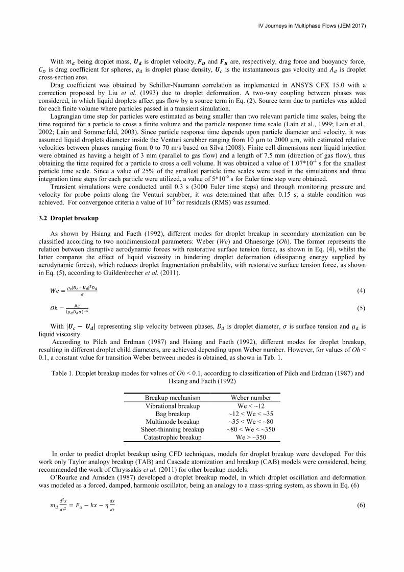
According to Pilch and Erdman (1987) and Hsiang and Faeth (1992), different modes for droplet breakup,
resulting in different droplet child diameters, are achieved depending upon Weber number. However, for values of Oh <
0.1, a constant value for transition Weber between modes is obtained, as shown in Tab. 1.
Table 1. Droplet breakup modes for values of Oh < 0.1, according to classification of Pilch and Erdman (1987) and
Hsiang and Faeth (1992)
Breakup mechanism Weber number
Vibrational breakup We < ~12
Bag breakup ~12 < We < ~35
Multimode breakup ~35 < We < ~80
Sheet-thinning breakup ~80 < We < ~350
Catastrophic breakup We > ~350
In order to predict droplet breakup using CFD techniques, models for droplet breakup were developed. For this
work only Taylor analogy breakup (TAB) and Cascade atomization and breakup (CAB) models were considered, being
recommended the work of Chryssakis et al. (2011) for other breakup models.
O’Rourke and Amsden (1987) developed a droplet breakup model, in which droplet oscillation and deformation
was modeled as a forced, damped, harmonic oscillator, being an analogy to a mass-spring system, as shown in Eq. (6)
𝑚𝑑
𝑑2𝑥
𝑑𝑡2= 𝐹𝑎 − 𝑘𝑥 − 𝜂
𝑑𝑥
𝑑𝑡 (6)

Zerwas, A.A. and Paiva, J.L. CFD simulation of two-phase flow in a Venturi scrubber: Validation and comparison of secondary atomization models
With x being displacement from equilibrium position (droplet deformation), Fa is external force applied in the
system (aerodynamic force), k is spring stiffness (related to surface tension) and η is damping coefficient (related to
liquid viscosity).
Rewriting Eq. (6) in order a dimensionless deformation equation and considering the analogy explained before, one
can write Eq. (7), as implemented in ANSYS CFX (ANSYS, 2013) and explained in Marek (2013).
𝑑2𝑥
𝑑𝑡2=
𝐶𝑓𝜌𝑐|𝑼𝒄− 𝑼𝒅|2
𝐶𝑏𝜌𝑑
𝑟𝑑 2
−𝐶𝑘𝜎
𝜌𝑑
𝑟𝑑 3
�̂� −𝐶𝜂𝜇
𝑑
𝜌𝑑
𝑟𝑑 2
𝑑𝑥
𝑑𝑡 (7)
With �̂� being dimensionless deformation, rd is droplet radius and Cf, Cb, Ck and Cη are coefficients with values,
respectively, 0.33, 0.5, 8 and 5.
Droplet breakup occur only if �̂� exceeds unity and child droplet radius is obtained according to Eq. (7) based on
energy conservation balance.
𝑟𝑑
𝑟𝑐ℎ𝑖𝑙𝑑= 1 + 0.4𝐾 +
𝜌𝑑𝑟𝑑 3
𝜎
𝑑𝑥
𝑑𝑡(
6𝐾−5120
) (8)
With 𝑟𝑐ℎ𝑖𝑙𝑑 being child droplet radius after breakup and K have a value of 3.33.
Tanner (2004) developed a CAB model using the same criteria for droplet deformation given by O’Rourke and
Amsden (1987), however, 3 breakup modes were used for determining child droplet diameter, as shown in Eq. (9) and
Eq. (10).
𝑟𝑑
𝑟𝑐ℎ𝑖𝑙𝑑= 𝑒−𝐾𝑏𝑢𝑡𝑏𝑢 (9)
𝐾𝑏𝑢 = {
𝑘1𝜔
𝑘2𝜔𝑊𝑒0.5
𝑘3𝜔𝑊𝑒0.75
5 < 𝑊𝑒 < 80
80 < 𝑊𝑒 < 350𝑊𝑒 > 350
(10)
With 𝑡𝑏𝑢 being the time necessary for �̂� to exceed unity, 𝜔 is droplet oscillation frequency and k1, k2 and k3 are
constants given in ANSYS CFX (ANSYS, 2013).
4. RESULTS AND DISCUSSION
Pressure drop and Sauter mean diameter obtained by Silva (2008) throughout a large-scale Venturi scrubber were
compared with numerical simulations carried out in ANSYS CFX 15.0. A computational mesh was created around a
geometry similar to the one used experimentally by Silva (2008) and is outlined in Fig. 1, with dimensions given in
Tab. 2.
Figure 1. Schematic of a Venturi scrubber used by Silva (2008) with four liquid displacement positions
Table 2. Dimensions used for mesh creation in CFD software
Definition Dimensions
(mm)
Diameter (D) 250
Throat diameter (Dt) 122,5
Inlet length (lin) 500
Convergence section length (lc) 230
Throat section length (lt) 300

IV Journeys in Multiphase Flows (JEM 2017)
Divergent section length (ld) 740
Outlet length (lout) 1500
Computational mesh was achieved with a grid generation tool in the CFD software (Meshing), by first creating a
meshed region in the inlet face and afterwards, using this mesh as a base for creation of other element faces throughout
equipment, with a method called Sweep. The generated mesh consisted of 1,117 thousand hexahedral elements and
element cells are shown in Fig. 2 for different plane cuts. In bottom left a transversal cut in the beginning from
convergent section shows cell faces, while in bottom right, cell faces are show in the beginning from throat section.
Figure 2. Computational mesh for a circular Venturi scrubber, in which is shown for different plane cuts,
convergent and throat sections (upper part); transversal cut in convergent section (bottom left); and transversal cut in
throat section (bottom right)
According to Silva (2008), water was injected in convergent section through four different nozzles, as shown in
Fig. 1, with liquid flow rates varying from 0.0134 to 0.0583 kg/s and gas flow rates from 0.483 to 0.987 kg/s. In order
to compare with experimental data, simulations were conducted for a set of three gas flow rates (0.483, 0.861 and 0,987
kg/s) with a value of 0.0134 kg/s for water flow rate.
In order to compare droplet breakup models, a size distribution for liquid injection was not initially adopted and
therefore, computational parcels were injected near the wall with diameter of 1 mm. For gas flow rate of 0.861 kg/s,
computational particles positions were obtained with their current diameter in last time step (0.3 s) for TAB and CAB
models, as shown in Fig. 3.

Zerwas, A.A. and Paiva, J.L. CFD simulation of two-phase flow in a Venturi scrubber: Validation and comparison of secondary atomization models
Figure 3. Computational particle location in last time step (0.3 s) with their current diameter for a gas mass flow of
0.861 kg/s (throat velocity of 60 m/s) for different droplet breakup models: a) TAB; b) CAB
Comparing the two droplet breakup models, one obtains a similar droplet diameter reduction for all particles with
TAB model, whereas with CAB model, a variation in diameter reduction was achieved, resulting in droplets with
different diameters, along with a better liquid dispersion transversal to gas flow after droplet breakup, if compared with
TAB model. According to Fig. 3, one perceives that particles followed the same trajectory paths, with breakup
occurring in the beginning of throat section for TAB model, whilst breakup simulated by CAB model occurred along
throat section. For a higher gas flow rate, the same patterns were observed for the two models, not being reported in this
work.
In order to compare the numerical simulation results with the experimental data obtained by Silva (2008) and
literature correlations, as shown in Tab. 3, the Sauter mean diameter (D32) was analyzed. Venturi scrubber length was
divided in a series of control volumes with width of 2 cm and computational particles between simulation times of 0.15
s to 0.3 s were analyzed with Eq. (11). As a result, Sauter mean diameter through the equipment was obtained, as
shown in Fig. 4, in which coordinate axis is given as distance to liquid injection.
𝐷32 =∑ 𝑛𝑑,𝑖𝑑𝑑,𝑖
3𝑚𝑖=1
∑ 𝑛𝑑,𝑖𝑑𝑑,𝑖 2𝑚
𝑖=1
(11)
With D32 being Sauter mean diameter, 𝑛𝑑,𝑖 is particle number rate, in which each computational particle relates to a
real number of droplets, 𝑑𝑑,𝑖is computational particle diameter and m represents total number of particles inside a
determined control volume.

IV Journeys in Multiphase Flows (JEM 2017)
Figure 4. Sauter mean diameter through Venturi scrubber length for different gas flow rates and breakup models
Table 3. Sauter mean diameter obtained with experimental correlations (Hsiang and Faeth, 1992; Wert, 1995) and
experimental data by Silva (2008), for different gas flow rates
Gas flow rate
(kg/s)
Sauter mean diameter
(Hsiang and Faeth, 1992)
(10-3
m)
Sauter mean diameter
(Wert, 1995)
(10-3
m)
Sauter mean diameter
(Silva, 2008)
(10-3
m)
0.483 0.170 0.242 0.3635
0.861 0.127 0.224 0.1750
0.987 0.119 0.193 0.2115
For the lowest gas flow rate, no breakup of the droplets for both models was achieved, which resulted in a bigger
difference between the experimental data and the simulated one, as seen by Fig. 4 and Tab. 3. However for higher gas
flow rates, the results obtained are in accordance with experimental data, with a Sauter mean diameter of 515 µm
obtained with numerical simulation, while a value of 211.5 µm for the experimental data (Silva, 2008) and a value of
193 µm with correlation of Wert (1995) was achieved. One can observe in Fig. 4 that for both gas flow rates, droplet
breakup simulated by TAB model resulted in droplet diameters of same size, whereas for CAB model, different Sauter
mean diameters were achieved in the end of the equipment. For the present reason, along with a better droplet
dispersion achieved, CAB model in conjunction with a droplet size distribution injection was studied.
According to Alonso et al. (2001) droplet size distribution through Venturi scrubbers can be descripted by Rosin-
Rammler equation, as given in Eq. (12), with parameter 𝑛1 varying from 1.7 to 2.2. A value of 2.15, as in Gonçalves et
al. (2004), along with a value of 1 mm for Sauter mean diameter.
1 − φ = exp (− (𝐷𝑑
𝑋1)
𝑛1
) (12)
With φ being cumulative volume fraction of droplets with diameter lower than Dd and X1 is a Sauter mean
diameter corrected by a gamma function.

Zerwas, A.A. and Paiva, J.L. CFD simulation of two-phase flow in a Venturi scrubber: Validation and comparison of secondary atomization models
Figure 5. Comparison of Sauter mean diameters through Venturi scrubber length for different gas flow, using
Rosin-Rammler size distribution (CAB - RR) and monodisperse injection (CAB).
Figure 5 compares droplet Sauter mean diameter through Venturi scrubber obtained with a Rosin-Rammler droplet
size distribution using CAB model with a 1mm diameter particle injection, as previously done. One perceives that using
a size distribution, droplet breakup was achieved in a shorter distance to liquid injection if compared to a monodisperse
injection, since a reduction in Sauter mean diameter occurred a shorter distance before throat section. For a gas flow
rate of 0.483 kg/s droplet breakup with CAB model was achieved, resulting in a lower value for Sauter mean diameter
for a droplet size distribution injection, since it is present droplets with bigger diameters, possessing bigger Weber
numbers and having higher probabilities of reducing their diameter. For a gas flow rate of 0.861 kg/s, a lower value for
Sauter mean diameter was obtained if compared to the previously simulation, whereas for highest flow rate, a similar
value was achieved. It was noted that using a droplet size distribution to model liquid injection resulted in droplet
breakup for all three cases.
In order to analyze droplet size evolution through the Venturi scrubber, droplet size distribution was evaluated in
four control volumes with 0.02 m width located from liquid injection: 0 m (liquid injection); 0.23 m (beginning from
throat section); 0.53 m (beginning from divergent section); 1.27 m (end of divergent section). Droplet size distribution
was obtained by separating each particle inside a control volume based in their diameter and adding their mass
contribution in their size interval. Figure 6 shows droplet size distribution for 3 gas flow rates distant 0.23 m from
liquid injection.
According to Fig. 6 one can obtain that droplet breakup was achieved for the three gas flow rates, since droplet size
distribution was dislocated to smaller droplet sizes. It was seen that increasing mass gas flow rate, smaller droplet size
distributions were achieved, since higher values for droplet Weber number were achieved. However, for the other two
control volumes, a quasi-uniform droplet size distribution was obtained for gas flow rates of 0.861 kg/s and 0.987 kg/s.
Due to the quasi-uniform droplet size distribution, rather than using a constant value of 1 mm for droplet diameter in
Rosin-Rammler function for droplet injection, droplet diameter for Rosin-Rammler function was chosen as being the
Sauter mean diameter after breakup have occurred for different gas flow rates.
Figure 7 shows droplet size distribution along the Venturi scrubber length for a gas flow rate of 0.861 kg/s. One
perceives that droplet breakup still occurred, even though droplets with smaller diameter were present, resulting in
lower Weber numbers. Using the mentioned criteria for determining droplet diameter in liquid injection resulted in a
droplet size distribution with a broader size distribution, if compared to the previous simulation results. For the highest
gas flow rate (0.987 kg/s) the same pattern were observed.

IV Journeys in Multiphase Flows (JEM 2017)
Figure 6. Droplet size distribution distant 0.23 m from liquid injection for 3 gas flor rates using CAB model and
Rosin-Rammler function
Figure 7. Droplet size distribution for different positions using CAB model and Rosin-Rammler function, for a gas
mass flow rate of 0.861 kg/s
5. CONCLUSIONS
The flow field inside a wet scrubber was simulated with a RANS model using Computational Fluid Dynamics
(CFD) in which the multiphase flow was solved by an Euler-Lagrange approach. TAB and CAB models were evaluated
for droplet breakup inside a Venturi scrubber. Broader size distributions were achieved using a Rosin-Rammler function
with droplet diameter obtained after droplet breakup. With the simulated data it can be seen that droplet breakup due to
secondary atomization plays an important role in varying droplet size distribution along the Venturi scrubber.
6. ACKNOWLEDGEMENTS
CAPES is gratefully acknowledged.
7. REFERENCES
Ahmadvand, F. and Talaie, M.R., 2010. “CFD modeling of droplet dispersion in a Venturi scrubber”. Chemical
Engineering Journal, Vol. 160, p. 423-431.
Ali, M., Qi, Y.C., Mehboob, K.A., 2012. “Review of performance of a Venturi scrubber”. Research Journal of Applied
Sciences, Engineering and Technology, Vol. 19, n. 4, p. 3811-3818.
Alonso, D.F., Gonçalves, J.A.S., Azzopardi, B.J., Coury, J.R., 2001. “Drop size measurements in Venturi scrubbers”.
Chemical Engineering Science, Vol. 56, p. 4901-4911.

Zerwas, A.A. and Paiva, J.L. CFD simulation of two-phase flow in a Venturi scrubber: Validation and comparison of secondary atomization models
ANSYS, 2013. CFX-Solver Theory Guide 15.0. ANSYS inc.
Boll, R.H., 1973. “Particle collection and pressure drop in Venturi scrubbers”. Industrial and Engineering Chemistry
Fundamentals, Vol. 12, n. 1, p. 40-50.
Chryssakis, C.A., Assanis, D.N., Tanner, F.X., 2011. “Atomization models”. Handbook of Atomization and Sprays, p.
215-231.
Fathikalajahi, J., Talaie, M.R., Taheri, M., 1995. “Theoretical study of liquid droplet dispersion in a Venturi scrubber”.
Journal of the Air and Waste Management, Vol. 45, n. 3, p. 181-185.
Gonçalves, J.A.S, Costa, M.A.M., Aguiar, M.L., Coury, J.R., 2004. “Atomization of liquids in a Pease-Anthony Venturi
Scrubber – Part II: Droplet dispersion”. Journal of Hazardous Materials, Vol. 116B, p. 147-157.
Gonçalves, J.A.S., Costa, M.A.M., Henrique, P.R., Coury, J.R., 2003. “Atomization of Liquids in a Pease-Anthony
Venturi Scrubber – Part I: Jet dynamics”. Journal of Hazardous Materials, Vol. 97B, p. 267-279.
Goniva, C., Tuković, Ž., Feilmayr, C., Bürgler, T., Pirker, S., 2009. “Simulation of offgas scrubbing by a combined
Eulerian-Lagrangian model”. In Proceedings of 7st International Conference on CFD in the Minerals and Process
Industries – CSIRO 2009. Melbourne, Australia.
Guerra, V.G., Béttega, R., Gonçalves, J.A.S., Coury, J.R., 2012. “Pressure drop and liquid distribution in a Venturi
scrubber – Experimental data and CFD simulation”. Industrial and Engineering Chemistry Research, Vol. 51, p.
8049-8060.
Guildenbecher, D.R., López-rivera, C., Sojka, P.E., 2011. “Droplet deformation and breakup”. Handbook of
Atomization and Sprays, p. 145-156.
Heumann, W.L., 1997. Industrial Air Pollution Control Systems, McGraw-Hill Inc., New York.
Hsiang, L.P. and Faeth, G.M., 1992. “Near-limit drop deformation and secondary breakup”. International Journal of
Multiphase Flow, Vol. 18, n. 5, p. 635-652.
Laín, S. and Sommerfeld, M., 2003. “Turbulence modulation in dispersed two-phase flow laden with solids from a
Lagrangian perspective”. International Journal of Heat and Fluid Flow. Vol. 24, n. 4, p. 616-625.
Laín, S. and Sommerfeld, M., 2007. “A study of the pneumatic conveying of non-spherical particles in a turbulent
horizontal channel flow”. Brazilian Journal of Chemical Engineering, Vol. 24, n. 4, p. 535-546.
Laín, S., Bröder, D., Sommerfeld, M., Göz, M.F., 2002. “Modelling hydrodynamics and turbulence in a bubble column
using the Euler-Lagrange procedure”. International Journal of Multiphase Flow, Vol. 28, p. 1381-1407.
Laín, S., Bröder, D., Sommerfeld, M.,1999. “Experimental and numerical studies of the hydrodynamics in a bubble
column”. Chemical Engineering Science, Vol. 54, p. 4913-4920.
Liu, B., Mather, D., Reitz, R.D., 1993. “Effects of drop drag and breakupon fuel sprays”. SAE Technical Paper, n.
930072.
Majid, A., Changqi, Y., Zhongning, S., Jianjun, W., Haifeng, G., 2013. “CFD simulation of dust particle removal
efficiency of a Venturi scrubber in CFX”. Nuclear Engineering and Design, Vol. 256, p. 169-177.
Marek, M., 2013. “The double-mass model of drop deformation and secondary breakup”. Applied Mathematical
Modelling, Vol. 37, p. 7919-7939.
O’Rourke, P.J. and Amsden, A.A., 1987. “The TAB method for numerical calculation of spray droplet breakup”. SAE
Technical Paper, n. 872089.
Pak, S.I. and Chang, K.S., 2006. “Performance estimation of a Venturi scrubber using a computational model for
capturing dust particles with liquid spray”. Journal of Hazardous Materials, Vol. 138B, p. 560-573.
Pilch, M. and Erdman, C.A., 1987. “Use of breakup time data and velocity history data to predict the maximum size of
stable fragments for acceleration-induced breakup of a liquid drop”. International Journal of Multiphase Flow, Vol.
13, p. 741-757.
Shafiri, A. and Mohebbi, A., 2014. “A combined CFD modeling with population balance equation to predict pressure
drop in Venturi scrubbers”. Research on Chemical Intermediates, Vol. 40, n. 3, p. 1021-1042.
Silva, A.M., 2008. Numerical and experimental study of Venturi scrubbers, Ph.D. thesis, Universidade de Minho,
Portugal.
Talaie, M.R., Fathikalajahi, J., Taheri, M., 2008. “Prediction of droplet dispersion and particle removal efficiency of a
Venturi scrubber using distribution functions”. Iranian Journal of Science and Technology, Vol. 32, n. B1, p. 25-38.
Tanner, F.X., 2004. “Development and validation of a cascade atomization and drop breakup model for high-velocity
dense sprays”. Atomization and Sprays, Vol. 14, p. 211-242.
Viswanathan, S., Gnyp, A.W., St. Pierre, C.C., 1984. “Examination of gas-liquid flow in a Venturi scrubber”. Industrial
and Engineering Chemistry Fundamentals, Vol. 23, n. 3, p. 303-308.
Wert, K.L., 1995. “A rationally-based correlation of mean fragment size for drop secondary breakup”. International
Journal of Multiphase Flow, Vol. 21, n. 6, p. 1063-1071.
8. RESPONSIBILITY NOTICE
The authors are the only responsible for the printed material included in this paper.