
CFD Combustion Modeling and Validation of a Bagasse Boiler...• Flue gas recycling, reduce excess...
23
CFD Combustion Modeling and Validation of a Bagasse Boiler 22 July 2014
Transcript of CFD Combustion Modeling and Validation of a Bagasse Boiler...• Flue gas recycling, reduce excess...

CFD Combustion Modeling and Validation of a Bagasse Boiler
22 July 2014

Overview
• Why CFD?
• What is Computational Fluid Dynamics (CFD)?
• Industrial Applications
• Case Study – Industrial Watertube Boiler Firing Bagasse
• Combustion
• Turbulence
• Heat transfer
• Validation
• Suction Pyrometer
• Thermal Camera
• Other Example Case Studies
• Conclusion

1. User defines
the problem
4. Solve the
equations
2. Construct
geometry and
mesh
3. Define boundary
conditions and physical
models
5. Interpret
the results
What is Computational Fluid Dynamics (CFD)? ?Process
Dell T7610
workstations

Why CFD?
• Traditional methods
Global combustion reactions
Lumped parameter heat transfer calculations – empirical
simplification
• Not ideal for NEW developments
• Modern standards require a higher
level of detail
• Computer test platform

Industrial Applications
• Improve heat exchanger performance – 3D
• Temperature distribution on walls –stresses
• Flue gas recycling, reduce excess air, control furnace gas
temperatures,
reduce NOX,improve boiler efficiency
• New secondary air systems - increased furnace capacity
• Lower emissions
• Diagnostic tests
• New fuels
• Erosion, fouling, corrosion
• Control
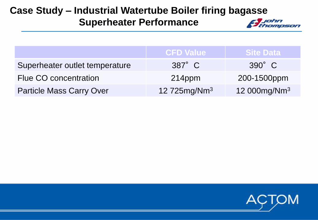
CFD Value Site Data
Superheater outlet temperature 387°C 390°C
Flue CO concentration 214ppm 200-1500ppm
Particle Mass Carry Over 12 725mg/Nm3 12 000mg/Nm3
Case Study – Industrial Watertube Boiler firing bagasse
Superheater Performance

Physics – Combustion / Turbulence
Furnace
Superheater
Air
Fuel

Physics – Heat Transfer

Validation - Suction Pyrometer
SH

Validation - Suction Pyrometer

Suction Pyrometer Data vs CFD

Suction Pyrometer Data vs CFD

Suction Pyrometer Data vs CFD
Species distribution CO and O2

Suction Pyrometer Data vs CFD
240
260
280
300
320
340
360
380
400
420
30 40 50 60 70 80 90 100 110
Ste
am
Te
mp
(d
eg
C)
Load (%)
Superheater Temp vs Load Characteristic
Measurements
CFD

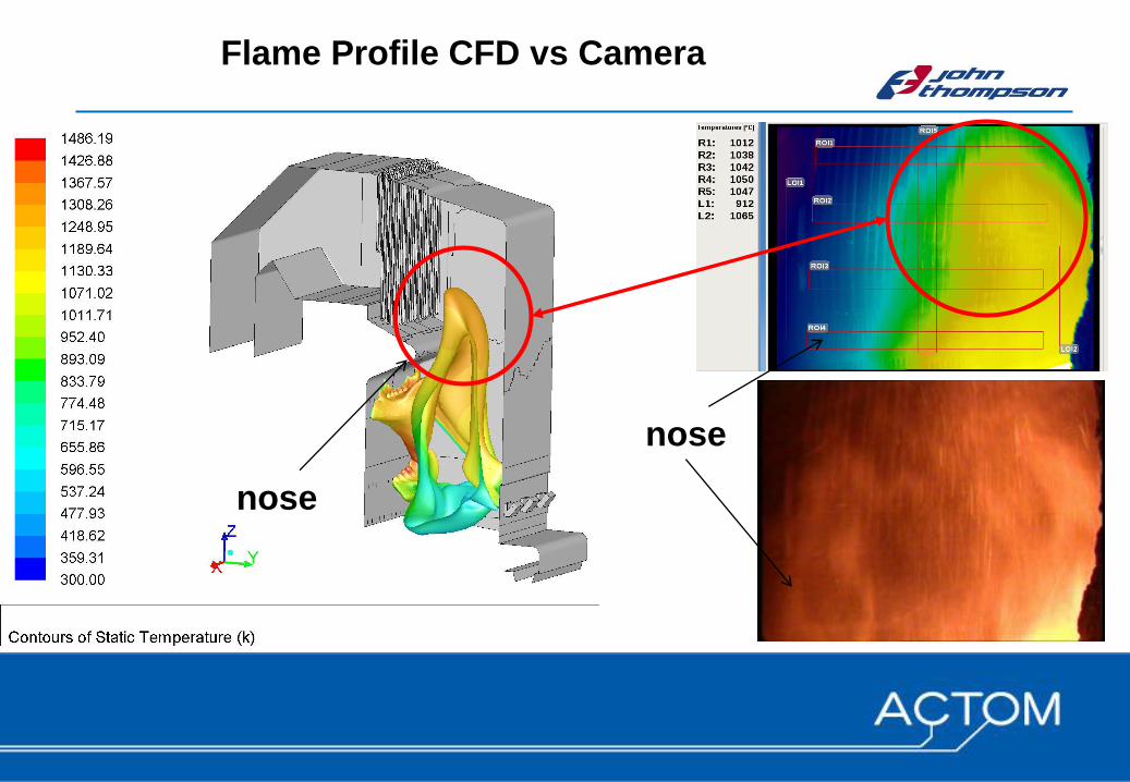
Thermal Camera

Thermal Camera - Front of Superheater
CFD Suction pyrometer
Thermal camera
(R1)
Upper level temperature
in front of superheater
[°C] 1020 1040 1055
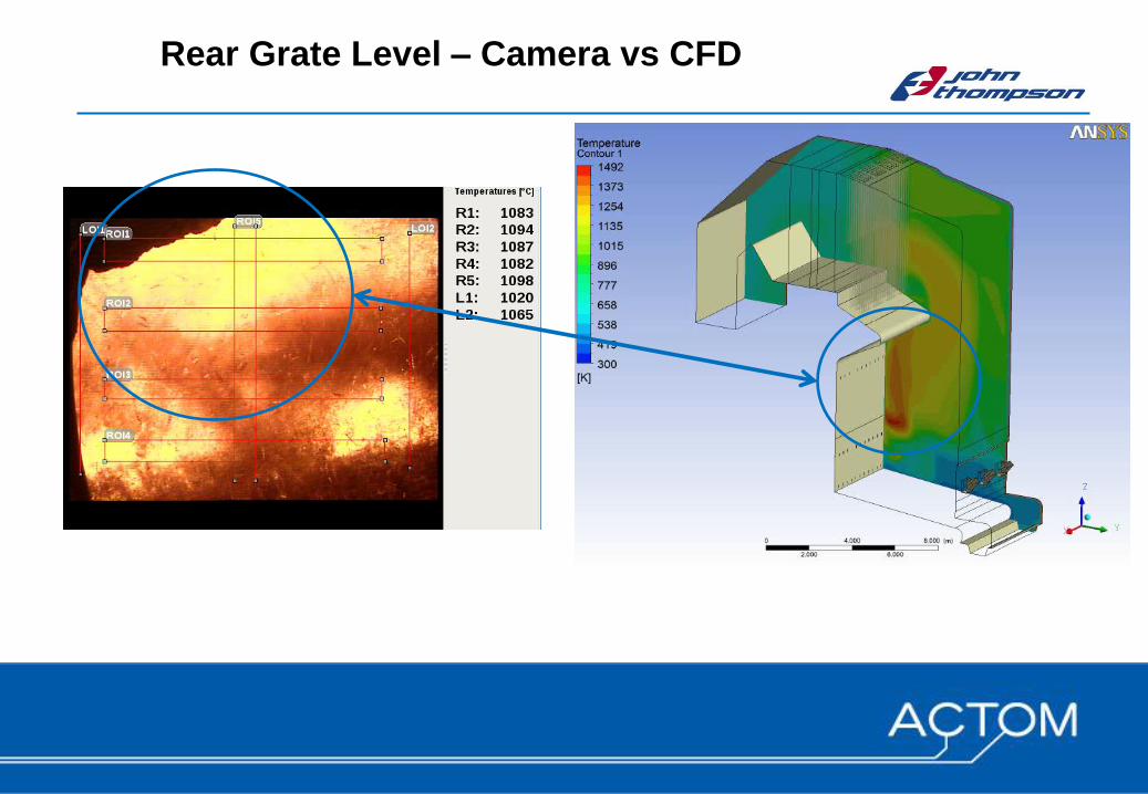
Rear Grate Level – Camera vs CFD

Physics – Combustion / Turbulence
• Pilot plant testing
• Model conditions at inlet of
Superheater = critical
• Effect of turbulence on heat
transfer – up to 50% increase

• Why?
• Predicting steam temperature is
not new.
• Cogeneration – higher steam
Temperature = larger superheaters
• More detailed modelling required
Direct Application

More Example Case Studies - Erosion

Conclusion
• CFD = state of the art – combustion modelling
• Advances in computers - accuracy feasible
• Combustion with heat transfer – novel
• IMPERATIVE to understand the physics
of the problem
• Validation = KEY!!!!
• Industrial scale 120MW thermal
(25MW electric) – 28 million cells
• 5 days to solve

THANK YOU