CFD Analysis of Mixing and Combustion of a Hydrogen · PDF fileAbstract - A numerical study of...
8
Abstract - A numerical study of combustion enhancement has been performed for a Mach 2 model scramjet (supersonic combustion ramjet) combustor. The configuration used is similar to the DLR (German Aerospace Center) scramjet model and it is consists of a one-sided divergent channel with a wedge-shaped flame holder. Fuel (hydrogen) is injected at supersonic speed through the rear of a circular strut injector located at the channel symmetry axis. The shape of the strut is chosen in a way to produce strong stream wise vorticity and thus to enhance the hydrogen/air mixing. Strength and size of the vortices are defined by the strut geometry and may be modified. Numerically predicted profiles of static pressure, axial velocity, and static temperature for both non-reacting as well as reacting flows are compared with the experimental data. The RANS calculations are able to predict the mean and fluctuating quantities reasonably well in most regions of the flow field. Subsonic regions at the channel symmetry axis are responsible for flame holding. If the combustor geometry is chosen in a favorable way these subsonic zones may be kept small. The k-ε computations are capable of predicting mixing and combustion simulations well and good. Index terms- Flameholder, k-ε model, Scramjet and Supersonic combustion. I. INTRODUCTION The Supersonic Combustion Ramjet (SCRAMJET) engine has been recognized as the most promising air breathing propulsion system for the hypersonic flight (Mach number above 5). In recent years, the research and development of scramjet engine has promoted the study of combustion in supersonic flows. Extensive research is being carried out over the world for realizing the scramjet technology with hydrogen fuel with significant attention focused on new generations of space launchers and global fast-reaction reconnaissance missions. However, application for the scramjet concept using high heat sink and hydrogen fuels offers significantly enhanced mission potential for future military tactical missiles. Scramjet being an air-breathing engine, the performance of the missile system based on the scramjet propulsion is envisaged to enhance the payload weight and missile range. Supersonic combustion ramjet engine for an air-breathing propulsion system has been realized and demonstrated by USA on ground and in flight. X-43 vehicle used hydrogen fuel. Hydrocarbon fuel scramjet engine is still under study and research. Mixing, ignition and flame holding in Manuscript Received 07 January, 2011, revised October 10, 2011. K.M.Pandey and T.Sivasakthivel are with Department of Mechanical Engineering, N.I.T Silchar, Assam, India (email: [email protected]; [email protected] combustor, ground test facilities and numerical simulation of Scramjet engine are the critical challenges in the development of scramjet engine. A. Mixing, Ignition and flame holding in a scramjet combustor Among the critical components of the scramjet engine, the combustor presents the most formidable problems. The complex phenomenon of supersonic combustion involves turbulent mixing, shock interaction and heat release in supersonic flow. The flow field within the combustor of scramjet engine is very complex and poses a considerable challenge in design and development of a supersonic combustor with an optimized geometry. Such combustor shall promote sufficient mixing of the fuel and air so that the desired chemical reaction and thus heat release can occur within the residence time of the fuel -air mixture. In order to accomplish this task, it requires a clear understanding of fuel injection processes and thorough knowledge of the processes governing supersonic mixing and combustion as well as the factors, which affects the losses within the combustor. The designer shall keep in mind the following goals namely, • Good and rapid fuel air mixing • Minimization of total pressure loss • High combustion efficiency. B. Scramjet Fuel Injection system Due to the extremely short residence time of the air in supersonic combustors, an efficient (rapid and with small losses in total pressure) fuel/air mixing is hard to achieve. Nevertheless this is an important issue to keep the combustor length short and to reduce the skin friction drag. In supersonic flows a rapid fuel/air mixing additionally suffers from inherently low mixing rates due to compressibility effects at high convective Mach numbers. There are mainly two concepts for fuel injection in supersonic combustors: Wall injectors, where hydrogen is injected through the wall (normal or oblique to the main flow) or by ramps mounted to the wall, Strut injectors, which are located at the channel axis and directly, inject the fuel into the core of the air stream. In some cases both types of injectors approach each other, e.g. if a ramp injector extends over most of the channel height. A good near field mixing can be achieved by wall injection. On the other hand transverse injection systems cause a significant blockage of the flow resulting in irreversibility’s due to shock waves and thrust losses. Another concern is that the penetration of the fuel jet may be insufficient for real size combustors. In wall injectors no losses in total pressure if they are switched off. The last point is in contrast to ramp or CFD Analysis of Mixing and Combustion of a Hydrogen Fueled Scramjet Combustor with a Strut Injector by Using Fluent Software K.M.Pandey, Senior Member, IACSIT and T.Sivasakthivel IACSIT International Journal of Engineering and Technology, Vol. 3, No. 5, October 2011 446
Transcript of CFD Analysis of Mixing and Combustion of a Hydrogen · PDF fileAbstract - A numerical study of...

Abstract - A numerical study of combustion enhancement has been performed for a Mach 2 model scramjet (supersonic combustion ramjet) combustor. The configuration used is similar to the DLR (German Aerospace Center) scramjet model and it is consists of a one-sided divergent channel with a wedge-shaped flame holder. Fuel (hydrogen) is injected at supersonic speed through the rear of a circular strut injector located at the channel symmetry axis. The shape of the strut is chosen in a way to produce strong stream wise vorticity and thus to enhance the hydrogen/air mixing. Strength and size of the vortices are defined by the strut geometry and may be modified. Numerically predicted profiles of static pressure, axial velocity, and static temperature for both non-reacting as well as reacting flows are compared with the experimental data. The RANS calculations are able to predict the mean and fluctuating quantities reasonably well in most regions of the flow field. Subsonic regions at the channel symmetry axis are responsible for flame holding. If the combustor geometry is chosen in a favorable way these subsonic zones may be kept small. The k-ε computations are capable of predicting mixing and combustion simulations well and good.
Index terms- Flameholder, k-ε model, Scramjet and Supersonic combustion.
I. INTRODUCTION The Supersonic Combustion Ramjet (SCRAMJET) engine
has been recognized as the most promising air breathing propulsion system for the hypersonic flight (Mach number above 5). In recent years, the research and development of scramjet engine has promoted the study of combustion in supersonic flows. Extensive research is being carried out over the world for realizing the scramjet technology with hydrogen fuel with significant attention focused on new generations of space launchers and global fast-reaction reconnaissance missions. However, application for the scramjet concept using high heat sink and hydrogen fuels offers significantly enhanced mission potential for future military tactical missiles. Scramjet being an air-breathing engine, the performance of the missile system based on the scramjet propulsion is envisaged to enhance the payload weight and missile range.
Supersonic combustion ramjet engine for an air-breathing propulsion system has been realized and demonstrated by USA on ground and in flight. X-43 vehicle used hydrogen fuel. Hydrocarbon fuel scramjet engine is still under study and research. Mixing, ignition and flame holding in
Manuscript Received 07 January, 2011, revised October 10, 2011. K.M.Pandey and T.Sivasakthivel are with Department of Mechanical
Engineering, N.I.T Silchar, Assam, India (email: [email protected]; [email protected]
combustor, ground test facilities and numerical simulation of Scramjet engine are the critical challenges in the development of scramjet engine.
A. Mixing, Ignition and flame holding in a scramjet combustor
Among the critical components of the scramjet engine, the combustor presents the most formidable problems. The complex phenomenon of supersonic combustion involves turbulent mixing, shock interaction and heat release in supersonic flow. The flow field within the combustor of scramjet engine is very complex and poses a considerable challenge in design and development of a supersonic combustor with an optimized geometry. Such combustor shall promote sufficient mixing of the fuel and air so that the desired chemical reaction and thus heat release can occur within the residence time of the fuel -air mixture. In order to accomplish this task, it requires a clear understanding of fuel injection processes and thorough knowledge of the processes governing supersonic mixing and combustion as well as the factors, which affects the losses within the combustor. The designer shall keep in mind the following goals namely,
• Good and rapid fuel air mixing • Minimization of total pressure loss • High combustion efficiency.
B. Scramjet Fuel Injection system Due to the extremely short residence time of the air in
supersonic combustors, an efficient (rapid and with small losses in total pressure) fuel/air mixing is hard to achieve. Nevertheless this is an important issue to keep the combustor length short and to reduce the skin friction drag. In supersonic flows a rapid fuel/air mixing additionally suffers from inherently low mixing rates due to compressibility effects at high convective Mach numbers. There are mainly two concepts for fuel injection in supersonic combustors: Wall injectors, where hydrogen is injected through the wall (normal or oblique to the main flow) or by ramps mounted to the wall, Strut injectors, which are located at the channel axis and directly, inject the fuel into the core of the air stream.
In some cases both types of injectors approach each other, e.g. if a ramp injector extends over most of the channel height. A good near field mixing can be achieved by wall injection. On the other hand transverse injection systems cause a significant blockage of the flow resulting in irreversibility’s due to shock waves and thrust losses. Another concern is that the penetration of the fuel jet may be insufficient for real size combustors. In wall injectors no losses in total pressure if they are switched off. The last point is in contrast to ramp or
CFD Analysis of Mixing and Combustion of a Hydrogen Fueled Scramjet Combustor with a Strut Injector by Using
Fluent Software K.M.Pandey, Senior Member, IACSIT and T.Sivasakthivel
IACSIT International Journal of Engineering and Technology, Vol. 3, No. 5, October 2011
446
strut injectors which may not be removed from the flow field if no hydrogen is injected. Moreover, the injected hydrogen usually acts as a coolant for the strut. Alternative to physical ramp injectors are aero ramps which have a similar physical behavior but lower pressure losses. Aero ramps are multi-hole transverse injectors which induce pairs of counter-rotating vortices to improve mixing and fuel penetration. If strut injectors are used, usually all or most of the fuel is injected in main flow direction. This is possible without the induction of strong shock waves. Moreover, additional momentum is added by parallel fuel injection increasing the engine thrust. This may become important at high flight Mach numbers (10–15). Due to the limited mixing capabilities of parallel high speed streams, techniques for mixing enhancement are required. This can be achieved either by the use of shock waves or by creation of stream wise vorticity. Stream wise vortices may be induced by favorable chosen strut geometry.
Hydrogen should be injected in such a way that a good mixing is achieved over a short length resulting in a homogeneous temperature distribution. Local temperature peaks have to be avoided as to keep dissociation losses and nitrogen oxides low. An important issue at low flight Mach numbers of a scramjet is auto ignition. Due to relatively low air static temperatures this may become a problem for axial strut injectors which only induce weak shock waves and small recirculation zones downstream of the strut. Thus the advantage of avoiding normal shock waves may cause problems for a stable ignition. Four different modes of combustion may be distinguished for strut injectors: • A stable combustion where the flame is (attached) anchored directly downstream of the strut, • A stable combustion with a lifted flame which may be stabilized by shock waves and/or a subsonic zone, • Blow-off of the flame due to unfavorable thermodynamic conditions or bad mixing, • Thermal choking where the heat release is too high, the flame is moving upstream, and a normal shock causes subsonic flow in the combustor. The subsequent high temperatures usually will cause damage to the strut.
II. LITERATURE REVIEW Shigeru Aso et.al [1] worked on the topic of
“Fundamental study of supersonic combustion in pure air flow with use of shock tunnel”, and their findings are – The increase of injection pressure generated strong bow shock, resulting in the pressure loses. The shock generator is an effective method to accelerate the combustion. The increase of the injection total pressure raises the penetration of fuel; thus, the reaction zone expands to the center of flow field. Kyung Moo Kim et.al [2] worked on the topic of “Numerical study on supersonic combustion with cavity-based fuel injection”, and their findings are – When the wall angle of cavity increases, the combustion efficiency is improved, but total pressure loss increased. When the offset ratio of upper to downstream depth of the cavity increases, the combustion efficiency as well as the total pressure loss decreases. Yuan shengxue [3] worked on the topic of “supersonic
combustion”, and his findings are – The calculation of deflagration in supersonic flow shows that the entropy increment and the total pressure loss of the combustion products may decrease with the increase of combustion velocity. The oblique detonation wave angle may not be controlled by the wedge angle under weak under driven solution conditions and be determined only by combustion velocity. Gruenig and F. Mayinger [4] worked on the topic of “Supersonic combustion of kerosene/h2-mixtures in a model Scramjet combustor”, and their findings are – The necessary temperature level is partly achieved by the oblique shock waves in the supersonic flow with increasing combustor area ratio. K. Kumaran and V. Babu [5] worked on the topic of “Investigation of the effect of chemistry models on the numerical predictions of the supersonic combustion of hydrogen”, and their findings are – Multi step chemistry predicts higher and wider spread heat release than what is predicted by single step chemistry. The single step chemistry model is capable of predicting the overall performance parameters with considerably less computational cost. A better tradeoff between thrust augmentation and combustion efficiency can be achieved through staged combustion.
T. Cain and C. Walton [6] worked on the topic of “review of experiments on ignition and Flame holding in supersonic flow”, and their findings are – Low combustor entry temperature is desirable /essential due to intake and nozzle limitations. Hydrogen and hydrocarbon the optimum temperature /pressures are in regions in which ignition delay is very sensitive to temperature, varying from 0.1ms to >>10ms. At low Mach number and static temperatures but at these conditions combustion results in free subsonic regions with very high turbulence. Chemical initiators such as silane, fluorine and otto can be used but there are penalties in specific impulse, system complexity and handling hazards. G. Yu, J.G. Li, J.R. Zhao, et al. [7] worked on the topic of “An experimental study of kerosene combustion in a supersonic model combustor using effervescent atomization”, and their findings are – The smaller kerosene droplet having higher combustion efficiency. A local high temperature radical pool in the cavity is crucial in promoting the initiation and the subsequent flame holding of the kerosene combustion in a supersonic combustor. A.R.Srikrishnan and j. Kurian et.al. [8] worked on the topic of “An Experimental Investigation of Thermal Mixing and Combustion in Supersonic Flows”, and their findings are – A petal nozzle can achieve nearly uniform temperature and momentum fields by using mixing duct. The petal nozzle also results in better combustion, when it is used to inject the fuel-rich gases into a supersonic combustor. Temperature and pressure rises were measured and the supersonic combustion efficiency was found to be of the order of 60%. The performance of a conventional conical nozzle was found to be much inferior to that of the petal nozzle under identical conditions. M Deepu [9] worked on the topic of “Recent Advances in Experimental and Numerical Analysis of Scramjet Combustor Flow Fields”, and his findings are – Increase in jet to free stream momentum flux ratio will result in the increase of jet penetration to free stream for all kinds of jets. Injector orientation plays an important role in the strength of the bow shock, with the shocks created by oblique injector
IACSIT International Journal of Engineering and Technology, Vol. 3, No. 5, October 2011
447
being substantially weak compared to transverse injector. S. Zakrzewski and Milton [10] worked on the topic of “Supersonic liquid fuel jets injected into quiescent air”, and their findings are – Supersonic liquid jets M = 1.8 develops from a flat front to a rounded bow within some 10 mm M = 5.2, the bow shape is more pointed and shows signs of an oscillation from more to less pointed.
K.M.Pandey and T.Sivasakthivel [16] worked on the topic of “CFD Analysis of a Hydrogen Fueled Mixture in Scramjet Combustor with a Strut Injector by Using Fluent Software” they investigated supersonic cold flow with hydrogen injection. K.M.Pandey and Sivasakthivel.T [17] worked on the topic of “Recent Advances in Scramjet Fuel Injection - A Review”, and their findings are – Fuel injection techniques into scramjet engines are a field that is still developing today. The fuel that is used by scramjets is usually either a liquid or a gas. The fuel and air need to be mixed to approximately stoichiometric proportions for efficient combustion to take place. The main problem of scramjet fuel injection is that the airflow is quite fast, meaning that there is minimal time for the fuel to mix with the air and ignite to produce thrust (essentially milliseconds).Hydrogen is the main fuel used for combustion. Hydrocarbons present more of a challenge compared to hydrogen due to the longer ignition delay and the requirement for more advanced mixing techniques. Enhancing the mixing, and thus reducing the combustor length, is an important aspect in designing scramjet engines. There are number of techniques used today for fuel injection into scramjet engines. K.M.Pandey and Sivasakthivel.T [18] worked on the topic of "CFD Analysis of Mixing and Combustion of a Scramjet Combustor with a Planer Strut Injector," and they found that The static pressure distribution along the top and bottom walls for the case under the condition of engine ignition is much higher than that for the case under the condition of cold flow. There are three clear pressure rises on the top and bottom walls of the scramjet combustor. The eddy generated in the strut acts as a flame holder in the combustor, and it can prolong the residence time of the mixture in the supersonic flow.
III. GOVERNING EQUATIONS The advantage of employing the complete Navier-Stokes
equations extends not only to the investigations that can be carried out on a wide range of flight conditions and geometries, but also in the process the location of shock wave, as well as the physical characteristics of the shock layer, can be precisely determined. We begin by describing the three-dimensional forms of the Navier-Stokes equations below. Note that the two-dimensional forms are just simplification of the governing equations in the three dimensions by the omission of the component variables in one of the co-ordinate directions. Neglecting the presence of body forces and volumetric heating, the three-dimensional Navier-Stokes equations are derived as
IV. EXPERIMENTAL SETUP AND COMPUTATIONAL DETAILS
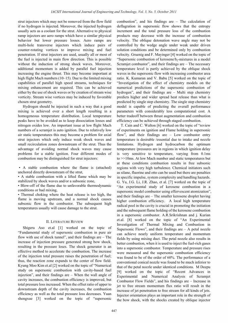
A schematic of the DLR (German Aerospace centre) scramjet experimental facility, [11–14], is presented in Fig. 1. Preheated air is expanded through a Laval nozzle and enters the combustor section at Ma = 2.0. The combustor has a width of 40 mm and a height of 50 mm at the entrance and a divergence angle of the upper channel wall of three degrees to compensate for the expansion of the boundary layer. A wedge shaped strut is placed in the combustion chamber downstream of the nozzle. Just downstream of the nozzle the height of the 32 mm long strut is 6 mm. along the first 100 mm downstream of the nozzle, the side walls and the upper wall are made from quartz glass to allow optical access and to minimize the reflection of scattered light on the wall opposite the observation window. Hydrogen (H2) is injected at Ma = 1.0 through a row of 15holes, 1.0 mm in diameter and 2.4 mm apart, in the strut base. Typical mass flows in the experiments were varied between 1.0 and 1.5 kg/s for the air and between 1.5 and 4.0 g/s for H2, which correspond to equivalence ratios between 0.034 and 0.136, respectively. The hydrogen is injected at ambient temperature and pressure, i.e. at T = 250 K and p =105Pa, whereas the air was injected at T = 340 K and p =105Pa. Combustion was initiated by pre-burning of a small amount of O2 in a H2 tube by a spark.
Figure.1 Schematic of the supersonic combustion chamber.
IACSIT International Journal of Engineering and Technology, Vol. 3, No. 5, October 2011
448
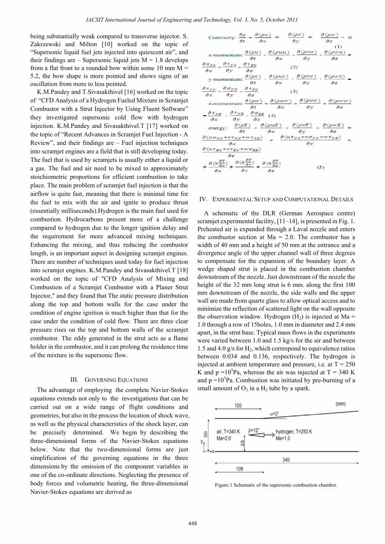
A. Gambit modelling of 3D Combustion Chamber and Strut Injector
In the computational configuration we are taking same DLR scramjet model so that we can validate our Result with Experimental Results but here we are using only 3 holes and gap between hole is 10mm this simplification is made to Reduce the Computational work.
Figure 2. 3D gambit modelling of DLR Scramjet Combustion Chamber and strut injector
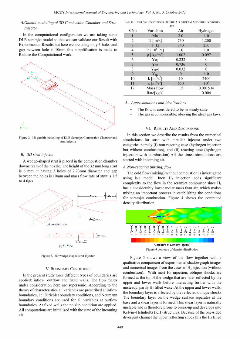
B. 3D strut injector
A wedge-shaped strut is placed in the combustion chamber downstream of the nozzle. The height of the 32 mm long strut is 6 mm, it having 3 holes of 2.23mm diameter and gap between the holes is 10mm and mass flow rate of strut is 1.5 to 4.0g/s.
Figure 3. 3D wedge shaped strut injector
V. BOUNDARY CONDITIONS In the present study three different types of boundaries are
applied: inflow, outflow and fixed walls. The flow fields under consideration here are supersonic. According to the theory of characteristics all variables are prescribed at inflow boundaries, i.e. Dirichlet boundary conditions, and Neumann boundary conditions are used for all variables at outflow boundaries. At fixed walls the no slip condition are applied. All computations are initialized with the state of the incoming air.
TABLE I: INFLOW CONDITIONS OF THE AIR STREAM AND THE HYDROGEN JET.
S.No Variables Air Hydrogen 1 Ma 2.0 1.0 2 U [ m/s] 730 1,200 3 T [k] 340 250 4 P [ 105 Pa] 1.0 1.0 5 ρ [ kg/m3] 1.002 0.097 6 Yo2 0.232 0 7 YN2 0.736 0 8 YH2o 0.032 0 9 YH2 0 1.0
10 k [m2/s2] 10 2400 11 ε [m2/s3] 650 108 12 Mass flow
Rate[kg/s] 1.5 0.0015 to
0.004
A. Approximations and Idealizations
• The flow is considered to be in steady state • The gas is compressible, obeying the ideal gas laws.
VI. RESULTS AND DISCUSSIONS In this section we describe the results from the numerical
simulations for strut with circular injector under two categories namely (i) non reacting case (hydrogen injection but without combustion), and (ii) reacting case (hydrogen injection with combustion).All the times simulations are started with incoming air.
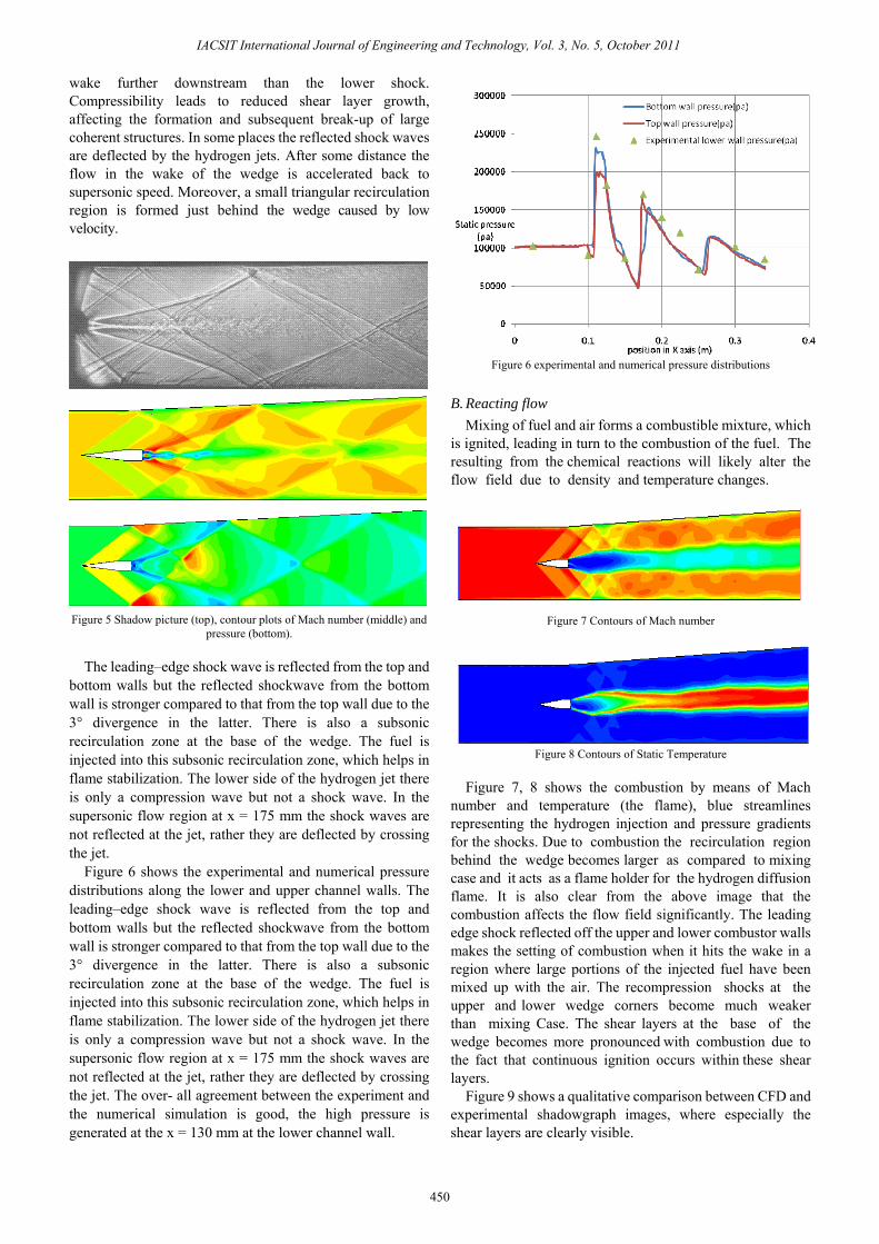
A. Non-reacting (mixing) flow The cold flow (mixing) without combustion is investigated
using k-ε model. Inert H2 injection adds significant complexity to the flow in the scramjet combustor since H2 has a considerably lower molar mass than air, which makes mixing an important process in establishing the conditions for scramjet combustion. Figure 4 shows the computed density distribution.
Figure 4 contours of density distribution
Figure 5 shows a view of the flow together with a
qualitative comparison of experimental shadowgraph images and numerical images from the cases of H2 injection (without combustion). With inert H2 injection, oblique shocks are formed at the tip of the wedge that are later reflected by the upper and lower walls before interacting further with the unsteady, partly H2 filled wake. At the upper and lower walls, the boundary layer is affected by the reflected oblique shocks. The boundary layer on the wedge surface separates at the base and a shear layer is formed. This shear layer is naturally unstable and is therefore prone to break-up and develops into Kelvin–Helmholtz (KH) structures. Because of the one-sided divergent channel the upper reflecting shock hits the H2 filled
IACSIT International Journal of Engineering and Technology, Vol. 3, No. 5, October 2011
449
wake further downstream than the lower shock. Compressibility leads to reduced shear layer growth, affecting the formation and subsequent break-up of large coherent structures. In some places the reflected shock waves are deflected by the hydrogen jets. After some distance the flow in the wake of the wedge is accelerated back to supersonic speed. Moreover, a small triangular recirculation region is formed just behind the wedge caused by low velocity.
Figure 5 Shadow picture (top), contour plots of Mach number (middle) and
pressure (bottom).
The leading–edge shock wave is reflected from the top and bottom walls but the reflected shockwave from the bottom wall is stronger compared to that from the top wall due to the 3° divergence in the latter. There is also a subsonic recirculation zone at the base of the wedge. The fuel is injected into this subsonic recirculation zone, which helps in flame stabilization. The lower side of the hydrogen jet there is only a compression wave but not a shock wave. In the supersonic flow region at x = 175 mm the shock waves are not reflected at the jet, rather they are deflected by crossing the jet.
Figure 6 shows the experimental and numerical pressure distributions along the lower and upper channel walls. The leading–edge shock wave is reflected from the top and bottom walls but the reflected shockwave from the bottom wall is stronger compared to that from the top wall due to the 3° divergence in the latter. There is also a subsonic recirculation zone at the base of the wedge. The fuel is injected into this subsonic recirculation zone, which helps in flame stabilization. The lower side of the hydrogen jet there is only a compression wave but not a shock wave. In the supersonic flow region at x = 175 mm the shock waves are not reflected at the jet, rather they are deflected by crossing the jet. The over- all agreement between the experiment and the numerical simulation is good, the high pressure is generated at the x = 130 mm at the lower channel wall.
Figure 6 experimental and numerical pressure distributions
B. Reacting flow Mixing of fuel and air forms a combustible mixture, which
is ignited, leading in turn to the combustion of the fuel. The resulting from the chemical reactions will likely alter the flow field due to density and temperature changes.
Figure 7 Contours of Mach number
Figure 8 Contours of Static Temperature
Figure 7, 8 shows the combustion by means of Mach number and temperature (the flame), blue streamlines representing the hydrogen injection and pressure gradients for the shocks. Due to combustion the recirculation region behind the wedge becomes larger as compared to mixing case and it acts as a flame holder for the hydrogen diffusion flame. It is also clear from the above image that the combustion affects the flow field significantly. The leading edge shock reflected off the upper and lower combustor walls makes the setting of combustion when it hits the wake in a region where large portions of the injected fuel have been mixed up with the air. The recompression shocks at the upper and lower wedge corners become much weaker than mixing Case. The shear layers at the base of the wedge becomes more pronounced with combustion due to the fact that continuous ignition occurs within these shear layers.
Figure 9 shows a qualitative comparison between CFD and experimental shadowgraph images, where especially the shear layers are clearly visible.
IACSIT International Journal of Engineering and Technology, Vol. 3, No. 5, October 2011
450
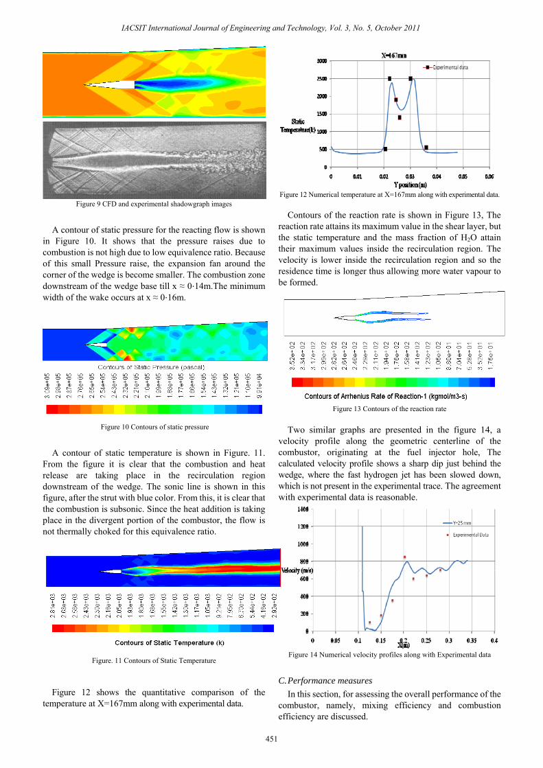
Figure 9 CFD and experimental shadowgraph images
A contour of static pressure for the reacting flow is shown in Figure 10. It shows that the pressure raises due to combustion is not high due to low equivalence ratio. Because of this small Pressure raise, the expansion fan around the corner of the wedge is become smaller. The combustion zone downstream of the wedge base till x ≈ 0⋅14m.The minimum width of the wake occurs at x ≈ 0⋅16m.
Figure 10 Contours of static pressure
A contour of static temperature is shown in Figure. 11. From the figure it is clear that the combustion and heat release are taking place in the recirculation region downstream of the wedge. The sonic line is shown in this figure, after the strut with blue color. From this, it is clear that the combustion is subsonic. Since the heat addition is taking place in the divergent portion of the combustor, the flow is not thermally choked for this equivalence ratio.
Figure. 11 Contours of Static Temperature
Figure 12 shows the quantitative comparison of the
temperature at X=167mm along with experimental data.
Figure 12 Numerical temperature at X=167mm along with experimental data.
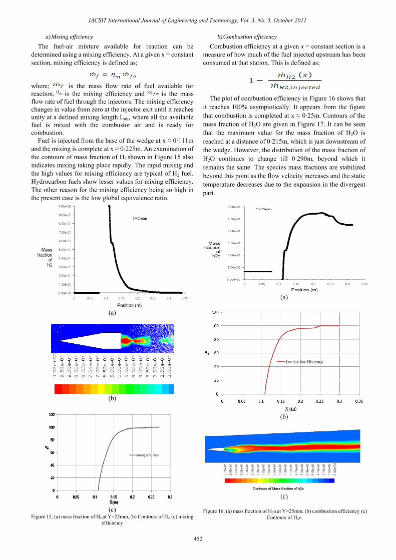
Contours of the reaction rate is shown in Figure 13, The
reaction rate attains its maximum value in the shear layer, but the static temperature and the mass fraction of H2O attain their maximum values inside the recirculation region. The velocity is lower inside the recirculation region and so the residence time is longer thus allowing more water vapour to be formed.
Figure 13 Contours of the reaction rate
Two similar graphs are presented in the figure 14, a
velocity profile along the geometric centerline of the combustor, originating at the fuel injector hole, The calculated velocity profile shows a sharp dip just behind the wedge, where the fast hydrogen jet has been slowed down, which is not present in the experimental trace. The agreement with experimental data is reasonable.
Figure 14 Numerical velocity profiles along with Experimental data
C. Performance measures In this section, for assessing the overall performance of the
combustor, namely, mixing efficiency and combustion efficiency are discussed.
IACSIT International Journal of Engineering and Technology, Vol. 3, No. 5, October 2011
451
a) Mixing efficiency The fuel-air mixture available for reaction can be
determined using a mixing efficiency. At a given x = constant section, mixing efficiency is defined as;
where; is the mass flow rate of fuel available for reaction, is the mixing efficiency and is the mass flow rate of fuel through the injectors. The mixing efficiency changes in value from zero at the injector exit until it reaches unity at a defined mixing length Lmix where all the available fuel is mixed with the combustor air and is ready for combustion.
Fuel is injected from the base of the wedge at x ≈ 0⋅111m and the mixing is complete at x ≈ 0⋅225m. An examination of the contours of mass fraction of H2 shown in Figure 15 also indicates mixing taking place rapidly. The rapid mixing and the high values for mixing efficiency are typical of H2 fuel. Hydrocarbon fuels show lesser values for mixing efficiency. The other reason for the mixing efficiency being so high in the present case is the low global equivalence ratio.
(a)
(b)
(c)
Figure 15, (a) mass fraction of H2 at Y=25mm, (b) Contours of H2, (c) mixing efficiency
b) Combustion efficiency Combustion efficiency at a given x = constant section is a
measure of how much of the fuel injected upstream has been consumed at that station. This is defined as;
The plot of combustion efficiency in Figure 16 shows that
it reaches 100% asymptotically. It appears from the figure that combustion is completed at x ≈ 0⋅25m. Contours of the mass fraction of H2O are given in Figure 17. It can be seen that the maximum value for the mass fraction of H2O is reached at a distance of 0⋅215m, which is just downstream of the wedge. However, the distribution of the mass fraction of H2O continues to change till 0⋅290m, beyond which it remains the same. The species mass fractions are stabilized beyond this point as the flow velocity increases and the static temperature decreases due to the expansion in the divergent part.
(a)
(b)
(c)
Figure 16, (a) mass fraction of H2o at Y=25mm, (b) combustion efficiency, (c)
Contours of H2o
IACSIT International Journal of Engineering and Technology, Vol. 3, No. 5, October 2011
452

VII. CONCLUSION Numerical simulation of 2D supersonic combustion using
realizable k-ε turbulence model have been carried out. Single step reaction kinetics has been used for modeling the chemistry. Comparison of the static pressure distribution on the bottom wall and middle section of the combustor and axial velocity variations at y =25mm show that the numerical predictions agree well with the experimental data. The k-ε model is able to predict the fluctuations well in those regions where the turbulence is reasonably isotropic. The static pressure of the case under the engine ignition condition is much higher than that of the case under the cold flow condition due to the intense combustion process. There are three obvious pressure rises on the top and bottom walls of the scramjet combustor because of the impingement of the reflected shock wave or the expansion wave on the walls. This illustrates that there exists the complex shock wave/shock wave interaction and the separation due to the interaction of the boundary layer and the oblique shock wave.
REFERENCES [1] Shigeru Aso, ArifNur Hakim, Shingo Miyamoto, Kei Inoue and
Yasuhiro Tani, “Fundamental study of supersonic combustion in pure air flow with use of shock tunnel”, Department of Aeronautics and Astronautics, Kyushu University, Japan , Acta Astronautica, vol 57, 2005, pp.384 – 389.
[2] Kyung Moo Kim 1, Seung Wook Baek and Cho Young Han, “Numerical study on supersonic combustion with cavity-based fuel injection”, International Journal of Heat and Mass Transfer, vol 47, 2004, pp.271–286.
[3] yuan Shengxue, “supersonic combustion”, vol. 42, no. 2, science in china (Series A), February 1999,
[4] C. Gruenig and f. Mayinger, “supersonic combustion of kerosene/h2-mixtures in a model scramjet combustor”, institute for thermodynamics, technical university Munich, and d-85747.
[5] K. Kumaran and V. Babu, “Investigation of the effect of chemistry models on the numerical predictions of the supersonic combustion of hydrogen”, Combustion and Flame, vol 156, 2009, pp.826–841.
[6] T. Cain and C. Walton “review of experiments on ignition and flame holding in supersonic flow” Published by the America Institute of Aeronautics and Astronautics, RTO-TR-AVT-007-V2.
[7] G. Yu, J.G. Li, J.R. Zhao, L.J. Yue, X.Y. Chang and C.-J. Sung “An experimental study of kerosene combustion in a supersonic model combustor using effervescent atomization”, Proceedings of the Combustion Institute, vol 30, 2005, pp. 2859–2866.
[8] a. R. Srikrishnan, j. Kurian and v. Sriramulu “an experimental investigation of thermal mixing and combustion in supersonic flows”, combustion and flame, vol 107, 1996, pp.464-474.
[9] M Deepu “Recent Advances in Experimental and Numerical Analysis of Scramjet Combustor Flow Fields”, Vol. 88, May 2007.
[10] S. Zakrzewski and Milton “Supersonic liquid fuel jets injected into quiescent air”, International Journal of Heat and Fluid Flow, vol 25, 2004, pp.833–840.
[11] M. Oschwald, R. Guerra and W. Waidmann, “International Symposium on Special Topics in Chemical Properties”, May 10–14,Scheveningen, 1993, pp. 498–503.
[12] W. Waidmann, F. Alff, U. Brummund, M. Bohm,W. Clauss, M. Oschwald, in: DGLR Jahrestagung, Erlangen, 1994, pp. 629–638.
[13] W. Waidmann, U. Brummund, J. Nuding, “8th International Symposium on Transport Phenomena in Comb”, July 16–20, San Francisco, USA, 1995, pp. 1473–1484.
[14] W. Waidmann, F. Alff, U. Brummund, M. Bohm,W. Clauss, M. Oschwald, Space Technology, vol 15, 1995, pp.421–429.
[15] Waidmann W., Alff F., Brummund U., Böhm M., Clauss W.,Oschwald M.: 1995, “Supersonic Combustion of Hydrogen/Air in a Scramjet Combustion Chamber”, Space Technology 15, p 421.
[16] K.M.Pandey and T.Sivasakthivel, "CFD Analysis of a Hydrogen Fueled Mixture in Scramjet Combustor with a Strut Injector by Using Fluent Software," International Journal of Engineering and Technology vol. 3, no. 2, pp. 109-115, 2011.
[17] K.M.Pandey and T.Sivasakthivel, "Recent Advances in Scramjet Fuel Injection - A Review," International Journal of Chemical Engineering and Applications vol. 1, no. 4, pp. 294-301, 2010.
[18] K.M.Pandey and T.Sivasakthivel, "CFD Analysis of Mixing and Combustion of a Scramjet Combustor with a Planer Strut Injector," International Journal of Environmental Science and Development vol. 2, no. 2, pp. 102-108, 2011.
K.M.Pandey did his PhD in Mechanical Engineering in 1994 from IIT Kanpur. He has published and presented 170 papers in International & National Conferences and Journals. Currently he is working as Professor of the Mechanical .Engineering Department, National Institute of Technology, Silchar, Assam, India..He also served the department in the capacity of head
from July 07 to 13 July 2010. He has also worked as faculty consultant in Colombo Plan Staff College, Manila, Philippines as seconded faculty from Government of India. His research interest areas are the following; Combustion, High Speed Flows, Technical Education, Fuzzy Logic and Neural Networks , Heat Transfer, Internal Combustion Engines, Human Resource Management, Gas Dynamics and Numerical Simulations in CFD area from Commercial Software’s.
T.Sivasakthivel did his M.Tech in Mechanical Engineering in 2011 from NIT Silchar. He has published 04 papers in International Journals. He has also worked as a Graduate Apprentice in BHEL Trichy from 2008 to 2009. His research interests are CFD, Combustion and Gasification.
IACSIT International Journal of Engineering and Technology, Vol. 3, No. 5, October 2011
453