CERTIFIED TECHNICIAN PROGRAM TRAINING MANUAL FOR … · CERTIFIED TECHNICIAN PROGRAM TRAINING...
119
Revised 2017 version 2 Indiana Department of Transportation CERTIFIED TECHNICIAN PROGRAM TRAINING MANUAL FOR Concrete Paving
Transcript of CERTIFIED TECHNICIAN PROGRAM TRAINING MANUAL FOR … · CERTIFIED TECHNICIAN PROGRAM TRAINING...

Revised 2017 version 2
Indiana Department of Transportation
CERTIFIED TECHNICIAN PROGRAM TRAINING MANUAL FOR
Concrete Paving

This material is to be used for training purposes only. Some of the procedures, field tests, and other operating procedures as described within these pages may be different than actual on-site procedures. Therefore, application should not be made without consideration of specific circumstances and current INDOT standards and policies.
11/15/11
Table of Contents Chapter One – Portland Cement Concrete Pavement Description….……………………………………………………………… 1-1 Types of Concrete Pavement ……………………………………………… 1-2 Plain Jointed Concrete Pavement
Reinforced Jointed Concrete Pavement Continuously Reinforced Concrete Pavement
Reinforced Concrete Bridge Approach Pavement Chapter Two – Preparation of the Grade Grade Preparation ………………………………………............................. 2-1 Subgrade ………………………………………………………………… 2-1 Subbase…………………………………………………………………… 2-2 Chapter Three – Concrete Job Control Materials …………….…………………………………………………… 3-1 Aggregates Portland Cement Fly Ash/GGBFS Water CMD Process……………………………………………………………... 3-6
Testing Equipment Calibration…………………………………………… 3-8 Reference Documents……………………………………………………. 3-8 Safety…………………………………………………………………….. 3-5 Sampling Concrete………………………………………………………. 3-9 Sampling from Concrete Trucks Sampling from Grade Sampling from Central Mixed Plant Testing Concrete………………………………………………………… 3-13 Pressure Method for Air content Volumetric Method for Air Content Unit Weight and Relative Yield Slump Making and Curing Test Specimens in the Field Flexural Strength Water/Cementitious Ratio Curing Concrete …………………………................................................. 3-16 Failed Materials………………………………………………………….. 3-16

Chapter Four- Equipment Concrete Plants ……………………………………………………………. 4-1 Central Mix Plant Ready-Mix Plant Delivery Equipment ………………………………………………………. 4-3 Paving Equipment ………………………………………………………… 4-5 Finishing Machine Spreader Slip-Form Pavers Hand Placement Finishing Equipment Tining Machine Vibrators Hand Equipment ………………………………………………………… 4-9 10 Foot Straightedge Tining Hand-Held Vibrators Saws …………………………………………………….............................. 4-11 Forms …………………………………………………………………… 4-12 Chapter 5 – Setting Forms Form Fitness ……………………………………………………………… 5-1 Subbase Support ……………………………………………………… 5-2 Form Setting ……………………………………………………………… 5-2 Grade and Alignments ………………………………………………… 5-2 Chapter 6 – The Paving Operation Condition of Subbase……………………………............................... 6-1 Dowel Bars and Assemblies ……………………………………………… 6-2 Mixing Concrete ………………………………………............................... 6-4 Weather Restrictions …………………………………………………… 6-6 Placing Concrete ……………………………………………………… 6-6 Placing Reinforcing Steel …………………………………………… 6-8 Strike Off, Consolidation, and Finishing ………………………………… 6-9 Floating Checking Finish and Surface Corrections Tining Edging Edge Slump …………………………………………………………… 6-15 Permanent Dates and Stations ……………………………... …………… 6-15 Curing …………………………………………………………………… 6-17 Wet Burlap Wet Straw Waterproof Blankets Liquid Membrane Forming Compound Protection from Rain ……………………………………………………… 6-18 Removal of Forms ………………………………………………………… 6-19

Chapter 7 – Pavement Joints Types of Joints …………………………………………………………… 7-2
Construction Joints D-1 Contraction Joints
Longitudinal Joints Transverse Construction Joints Terminal Joints Expansion Joints Retro-fitted Tie Bars Chapter 8 – Other Pavement Details and Requirements Ear Construction …………………………………………………… 8-1 Pavement Smoothness …………………………………………………… 8-1 Protection of Pavement …………………………………………………… 8-3 Opening Pavement to Traffic ……………………………………………… 8-3 Construction Vehicles Non-Construction Vehicles Pavement Thickness ……………………………………………................. 8-4 Coring Core Measurements Deficient Pavement Thickness…………………………………………… 8-5 Method of Measurement and Basis of Payment ………………………… 8-6 Chapter Nine- Concrete Pavement Patching Materials …………………………………………………………………... 9-1 Concrete Mix Design……………………………………………………… 9-2 Concrete Mix Criteria……………………………………………………… 9-2 Trial Batch Demonstration of CMDS……………………………………… 9-3 Acceptance………………………………………………………………… 9-3 Removal of Concrete……………………………………………………… 9-3 Partial Depth Patches Full Depth Patches Placement of Patching Materials………………………………………… 9-5 Partial Depth Patches Full Depth Patches Curing/Opening to Traffic………………………………………………… 9-8 Method of Measurement…………………………………………………… 9-9 Basis of Payment……………………………………………………………9-9

Chapter 10 – QC/QA PCCP and PCCP Sublots and Lots…………………………………………………………… 10-1 Random Sampling………………………………………………………… 10-2 Random Numbers Sample Location – Plastic Concrete Sample Location – Cores Sampling Procedure Trial Batch Demonstration………………………………………………… 10-8 QA Testing………………………………………………………………… 10-9 Flexural Strength Air Content Unit Weight Water/Cementitious Thickness Smoothness Pay Factors…………………………………………………………………. 10-11 Flexural Strength Air Content Thickness Smoothness Quality Assurance Adjustment…………………………………………… 10-12 Flexural Strength, Air Content, Air Content Range Thickness Smoothness Total Quality Assurance Adjustment Failed Materials…………………………………………………………… 10-16 Appeals…………………………………………………………………… 10-16 Flexural Strength Appeal for Sublot Air Content Appeal for Sublot
PCCP Acceptance…………………………………………………………. 10-16
1 Portland Cement Concrete Pavement Description Types of Concrete Pavement Plain Concrete Pavement Plain Jointed Concrete Pavement Reinforced Jointed Concrete Pavement Continuously Reinforced Concrete Pavement Reinforced Concrete Bridge Approach Pavement

1-1
CHAPTER ONE: PORTLAND CEMENT CONCRETE PAVEMENT
The pavement is the portion of the road that vehicles come in direct contact with. A rough pot-holed pavement is hard on vehicles and uncomfortable to the motorist. For these and many other reasons, a structurally sound, smooth riding, and long lasting pavement is very important. A quality pavement requires materials and construction practices in accordance with the design and specifications for the pavement. Those responsible for this quality are required to know how the pavement is built, the design and specifications requirements, and how to check for compliance of the design and specifications. There are several types of concrete pavements and requirements for their corresponding contraction joints. This chapter discusses the different types of concrete pavements and where to find the requirements for the pavements in the contract documents. ______________________________________________________________
DESCRIPTION
PCCP is composed of Portland cement concrete and, when specified, reinforcing steel and various joint materials. Concrete pavement is placed at the thickness specified in the plans or proposal and is constructed on a subbase course as required by the contract documents. The pavement is placed in reasonably close conformance to the lines, grades, and typical cross-sections (Figure 1-1) shown in the plans.
Concrete basically consists of Portland cement, water, and fine and coarse aggregates. A pozzolan material, such as fly ash, may be added to the concrete mix as a partial substitute for cement. The curing of the concrete is a chemical reaction of the Portland cement and water, which causes the concrete to shrink and crack. To control the cracking, transverse joints and longitudinal joints are constructed in the pavement. All pavements require transverse joints to control transverse cracking. These are sometimes known as contraction joints. Pavements wider than 16 feet require longitudinal joints to control longitudinal cracking. Pavements with transverse joints are referred to as jointed pavements.

1-2
TYPES OF CONCRETE PAVEMENT PLAIN JOINTED CONCRETE PAVEMENT
Plain jointed concrete pavement has no longitudinal reinforcing steel but is constructed with transverse joints (joints from edge of pavement to edge of pavement). The types of joints used are shown in Figure 1-1. Nearly all concrete pavements constructed by INDOT are of this type.
Figure 1-1. Plain Jointed Concrete Pavement
REINFORCED JOINTED CONCRETE PAVEMENT
Reinforced jointed concrete pavement is reinforced with steel mesh and is built with transverse joint spacing of 40 ft. Historically, this type of pavement was the predominant concrete pavement built by INDOT.
CONTINUOUSLY REINFORCED CONCRETE PAVEMENT
Continuously reinforced concrete (CRC) pavement is reinforced with a large amount of longitudinal steel (No. 5 bars, 6 inches on center) and only longitudinal joints as required. There are no transverse joints in this type of pavement. However, many of these pavements still exist and patching existing CRC pavements present some challenges compared to other types of concrete pavements.
REINFORCED CONCRETE BRIDGE APPROACH PAVEMENT
Reinforced concrete bridge approaches are built at the ends of a bridge with a minimum length of 20 ft 6 in.. They are generally reinforced with two mats of steel and are built to a specified thickness. The purpose of a bridge approach is to eliminate settlement of the pavement at the bridge ends. Since the bridge end bents are usually on piles, the bridge does not settle, but the end bent backfill usually experiences some settlement. The reinforced

1-3
concrete bridge approach pavement is usually supported by a pavement ledge on the bridge end and a terminal joint on the end adjacent to the concrete pavement. Additional information regarding reinforced concrete bridge approaches can be found in the 609-RCBA series of INDOT Standard Drawings.

2 Preparation of the Grade Grade Preparation Subgrade Subbase

2-1
CHAPTER TWO: PREPARATION OF THE GRADE
A concrete pavement is only as good as the grade on which the pavement is placed. In this chapter, the importance of subgrade preparation, the various types of subbase that may be used under the pavement, maintaining the constructed grade until paving begins, and the final trimming of the subgrade and subbase are discussed.
GRADE PREPARATION
The preparation of the subgrade and base course is a very important step since these materials have a considerable impact on the ride quality of the concrete pavement. Concrete bases and pavement are constructed on a subbase which is placed on a prepared subgrade.
SUBGRADE
Prior to constructing the subbase, the subgrade is to be constructed so that the material has a uniform density throughout. Any soft, yielding, or other unsuitable material is required to be removed and replaced if corrective measures are not effective. Proofrolling is done just prior to placing the subbase as per Section 203.26. Proofrolling for original ground or embankment construction shall be performed using a dump truck weighing at least 15 t. Proofrolling for subgrade preparation shall be performed using a dump truck weighing at least 33 t. All proofrolled surfaces shall be covered completely with a single pass. Operating speed of the proofrolling truck shall not exceed 2 mph. Deflections or rutting in excess of 1/2 in. shall require remediation of the surface as directed. Deflections or rutting in excess of 3 in. shall require corrective remediation measures and the Office of Geotechnical Services will be contacted. Proofrolling shall be performed after remediation measures on embankment or subgrade prior to the placement of additional material. There shall be one or two complete coverages as directed. Roller marks, irregularities, or failures shall be corrected. The uniform compaction, correction of unstable areas, and proofrolling of the subgrade should receive special attention at the form lines when forms are used for paving and at the track lines when the slip-form method is used. Settlement of the forms or tracks of the slip form paver due to poor subgrade stability results in a poor riding pavement.
2-2
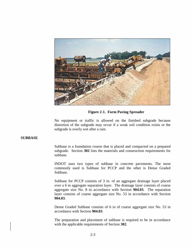
The subgrade is required to be well drained at all times. No subbase may be placed if the subgrade is frozen or muddy. The subgrade is required to be finished to within 1/2 in. of the true grade. This is important as there is a deduction for thin pavement. This deduction may be made for deficiencies greater than one tenth of an inch. In form paving, these tolerances are usually accomplished with a machine called a sub-grader which rides on the forms (Figure 2-1). The subgrade may be trimmed with a conventional grader. In slip form paving, an auto-grade machine with an automatic grade control sets the grade from a string line.
2-3
Figure 2-1. Form Paving Spreader
No equipment or traffic is allowed on the finished subgrade because distortion of the subgrade may occur if a weak soil condition exists or the subgrade is overly wet after a rain.
SUBBASE
Subbase is a foundation course that is placed and compacted on a prepared subgrade. Section 302 lists the materials and construction requirements for subbase. INDOT uses two types of subbase in concrete pavements. The most commonly used is Subbase for PCCP and the other is Dense Graded Subbase. Subbase for PCCP consists of 3 in. of an aggregate drainage layer placed over a 6 in aggregate separation layer. The drainage layer consists of coarse aggregate size No. 8 in accordance with Section 904.03. The separation layer consists of coarse aggregate size No. 53 in accordance with Section 904.03. Dense Graded Subbase consists of 6 in of coarse aggregate size No. 53 in accordance with Section 904.03. The preparation and placement of subbase is required to be in accordance with the applicable requirements of Section 302.

2-4
Compaction of the separation layer and dense graded aggregate shall compacted to achieve the maximum allowable deflection as determined with the Light Weight Deflectometer, LWD, testing in accordance with ITM 508. Compaction shall not occur if the moisture content of the aggregate is greater than 6.0%. The maximum allowable deflection will be determined from a test section or will be specified. Test section shall be constructed in accordance with ITM 514 for other materials not included in Table 1 to determine the maximum allowable deflection. The optimum moisture content will be determined in accordance with 203.4(a). Compaction of the drainage layer requires two passes with a vibratory roller before trimming and one pass with a tandem roller after trimming.
After the final trimming and compacting of Subbase for PCCP, depth determinations are required for each layer. The Technician should take measurements at a minimum frequency of one depth determination per each traffic lane for each 500 linear ft of each layer of subbase. The technician needs to keep a permanent record of all depth checks, including the date, location, and thickness of all checks. This record needs to be submitted with the final construction record to verify the quantity of material actually placed. If deficiencies are found in the thickness, appropriate measures are required to be taken. If more material is required, the additional material is mixed with the layer and the layer is re-compacted. Additional depth determinations are then obtained. The width of the subbase must also be checked and recorded by the Technician. The frequency of these width checks should match the depth check frequency. These checks are required to verify the quantity of material in cubic yards that were actually placed.

3 Concrete Job Control Materials Aggregates Portland Cement Fly Ash/GGBFS Water CMD Process Testing Equipment Calibration Referenced Documents Safety Sampling Concrete Sampling from Concrete Trucks Sampling from Grade Sampling from Central Mixed Plant Testing Concrete Pressure Method for Air Content
Volumetric Method for Air Content Unit Weight and Relative Yield Slump Making and Curing Test Specimens in the Field Flexural Strength Water/Cementitious Ratio Curing Concrete Failed Materials

3-1
CHAPTER THREE: CONCRETE JOB CONTROL
Concrete used in pavements on INDOT contracts must meet the requirements of Section 501 or 502. Concrete used as a base must meet the requirements of Section 305. Patching concrete must meet the requirements of Section 506. In order to verify that the concrete meets the applicable specification requirements, the Technician must perform job control sampling and testing of the freshly mixed and hardened concrete. Concrete pavements meeting the requirements of Section 501 are referred to as Quality Control/Quality Assurance Portland Cement Concrete Pavement, or QC/QA PCCP. Concrete pavements meeting the requirements of Section 502 are simply referred to as PCCP. Prior to concrete production, the Technician is required to participate in the trial batch demonstration, verify that the concrete plant is utilizing Certified Aggregate Producer Program, CAPP, approved aggregates as well as approved cement, fly ash, and admixtures. The Technician also determines if all job control testing equipment has been calibrated and is in good working order. The sampling and testing methods required by the contract and the frequency of each test in accordance with the Manual of Frequency for Sampling and Testing should be reviewed. The Manual for Frequency of Sampling and Testing and approved lists for the various materials used in concrete production can be found on the INDOT website.
MATERIALS
Paving concrete is basically composed of the following materials (Figure 3-1):
1) Fine aggregate 2) Coarse aggregate
3) Portland cement 4) Water

3-2
Additional materials that may be found in paving concrete are:
1) Fly Ash or Ground Granulated Blast Furnace Slag, GGBFS 2) Water-reducing admixture 3) Air-entraining admixture
Figure 3-1. Concrete Materials

3-3
The proportions of materials vary with different types of concrete. Prior to production of concrete, the Contractor is responsible for performance of the concrete mix design process, CMD. The Specifications outline the requirements of the process and additional information regarding the CMD process is included later in this chapter.
AGGREGATES
As mentioned previously, concrete mixes include two aggregate types. Fine aggregates are sands, usually meeting No. 23 aggregate gradation requirements. Concrete used in QC/QA PCCP may use an alternate gradation if identified in the Contractor’s Quality Control Plan, QCP. Coarse aggregates are larger particles, usually meeting the gradation requirements for coarse aggregate No. 8. Concrete used in QC/QA PCCP may also use an alternate coarse aggregate gradation if identified in the QCP. Section 904.02(d) requires that fine aggregate included in concrete used for base, pavement, and patching to be natural sands. Section 904.03 includes the classification requirements for coarse aggregate materials. The proportion of the aggregates is important to the integrity of the concrete and may affect the ultimate strength and the durability of the pavement. The fine aggregate is required to be 35 to 45% (35 to 50% for QC/QA PCCP) of the combined total weight of the coarse and fine aggregates (Figure 3-2).
Figure 3-2. Fine Aggregate/Coarse Aggregate Proportions

3-4
PORTLAND CEMENT
There are many different types of cement available for concrete. Only the following five are discussed:
1) Portland cement, Type I 2) Air-entrained Portland cement, Type I-A 3) Air-entrained Portland-pozzolan cement, Type IP-A 4) High early strength cement, Type III 5) Air-entrained high early strength cement, Type III-A
Under normal conditions, Portland cement, Type I is used in paving concrete. Air-entrained Portland cement, Type I-A, is cement that has been entrained with air during the manufacturing process and requires less air-entraining agent to be added to obtain the required air content. Portland-pozzolan cement, Type IP is similar to Type I, except that the cement also contains a pozzolan, such as fly ash, to reduce the cost. Air-entrained Portland-pozzolan cement, Type IP-A is similar to Type I-A, except that this cement also contains a pozzolan. When Portland cement, Type IP-A is used, fly ash/GGBFS specifications regarding allowable calendar periods apply. Portland cement, Type III obtains a high early strength. Portland cement, Type III-A is similar to Type III except that this cement contains entrained air from the manufacturing process. Unless otherwise specified, each cubic yard of paving concrete contains 564 lbs or six bags of cement. In order to verify that the concrete used in pavement meets this requirement, the Technician will perform a unit weight/relative yield test at the paving site as soon as the first load begins discharging. The results of this test determine the actual amount of cement in each cubic yard of concrete. If the cement content is determined to be high, the aggregate batch weights are required to be increased to lower the total cement content. If the cement content is too low, the aggregate batch weights are decreased to increase the cement content. Additional information regarding unit weight/relative yield testing follows later in this chapter.
FLY ASH/GGBFS
Fly ash is a powdery by-product of coal fired electrical generating plants which has similar structural properties as cement. GGBFS is a by-product of the steel production process that is produced in a molten condition in a

3-5
blast furnace and then cooled by immersing it in water. The use of fly ash or GGBFS reduces the cost of concrete by reducing the amount of cement required, but may extend the time needed to achieve the proper strength for opening the pavement to traffic. When fly ash or GGBFS is included in the concrete mix, the Technician is required to cast beams (Figure 3-3) in conjunction with each pour. The flexural strength of these beams is the only factor used to determine the opening of the pavement to traffic. Additional information related to flexural strength testing can be found later in this chapter.
Figure 3-3. Concrete Beam Used for Flexural Testing
The two types of fly ash used in PCCP are Class C and Class F. Class C fly ash has better structural qualities than Class F and is therefore the preferred type of fly ash. Sections 501.05 and 502.04, limit the times of the year that fly ash or GGBFS may be used.
The minimum cement/fly ash and minimum cement/GGBFS ratios for QC/QA PCCP are included in Section 501.05. For PCCP, Section 502.04 includes information related to the maximum cement reduction for fly ash replacement and the GGBFS/cement substitution ratios for regular paving concrete and high-early strength concrete mixes.
WATER When water is added to the cement, the setting and curing process begins. In a central-mix plant this process occurs in the mixing drum, and in a transit mix this process occurs in the truck mixer. Only clean, potable

3-6
water shall be used. Contaminated water may contain materials which are detrimental to the concrete after placement. After the water is added to the mix for concrete associated with PCC base, QC/QA PCCP, or PCCP, the concrete is required to be placed within 90 minutes if hauled in truck mixers or trucks equipped with agitators. If the hauling vehicles have no agitators, this time is reduced to 30 minutes if the concrete temperature is 90◦F or above and 45 minutes for cooler temperatures. The time the water is added to the concrete is stamped on the ticket at the concrete plant. For patching mixtures, the concrete must be placed within 30 minutes of the time that water is added if hauled in a truck with no agitators. If the truck has agitators or if a truck mixer is used, the concrete must be placed within 90 minutes of the time that water was added or within 30 minutes of introduction of calcium chloride solution, whichever is less.
The amount of water added at the plant varies from day to day depending upon the moisture contents of the fine and coarse aggregates used. If an overnight rain has caused the stockpiled materials to become wetter than the day before, less water is required to be added at the plant. Materials exposed to hot, dry conditions for several days require more water to be added. The mixture is required to contain no more water than is necessary to produce a concrete that is workable, plastic, and meets the slump requirements; however, the water-cementitious ratio is required to meet the specification limits at all times.
CMD PROCESS
The CMD process includes two steps. First the Contractor prepares a concrete mix design submittal, CMDS on a Department provided spreadsheet and sends it to the District Testing Engineer, DTE. This submittal is made at least 7 calendar days prior to the performance of a trial batch, if a trial batch is required by Section 501.06. The Technician will participate in the trial batch by performing side by side tests with Contractor personnel to verify that the CMDS is capable of meeting all requirements contained in Section 501.06 and to demonstrate the testing proficiency of Contractor personnel. Upon successful completion of the trial batch, the Contractor is required to submit documentation related to the second stage of the CMD process—the concrete mix design for production, CMDP. This submittal is required at least 3 work days prior to beginning of the paving operation and is made to the DTE. The Technician’s test results are required to accompany the Contractor’s CMDP submittal. Upon approval of the CMDP, the Contractor may begin production of the concrete for the paving operation. Should the Contractor’s CMDS not require a trial batch in accordance with Section 501.06, the DTE will review, process, and return the spreadsheet as an approved CMDP.

3-7
Once a CMDP is approved, the Contractor may alter the CMDP in one of the following fashions:
1) Change in materials as described in Section 501.04(a)
2) Adjustment to materials as described in Section 501.04(b)
3) Other adjustments as described in Section 501.04(c) When a change in materials is proposed for a concrete mix, a new CMDS reflecting the material change must be submitted by the Contractor to the DTE for approval. In this situation, the Contractor may perform a trial batch as described previously to verify the performance of the new CMDS or use concrete from the first day of production as the trial batch in accordance with Section 501.04(a). If the first production day is used as the trial batch, the Technician will coordinate sampling and testing with Contactor personnel to evaluate the concrete shortly after production begins. If random sampling requires that an acceptance test is to be performed during this first day of production, the acceptance testing can be used by the Technician to evaluate the new concrete mix design. If any Technician’s test result from samples taken during this first day of production indicates a failure to meet the specification requirements, the Technician must notify the PE/PS as soon as possible so the paving operation can be suspended. Any pavement constructed prior to the suspension of the paving operation will be treated as a failed material. Additional information regarding failed materials can be found later in this chapter. If the previously approved CMDP is adjusted in accordance with Section 501.04(b), the Contractor is required to submit information related to the material adjustment to the DTE for approval. After DTE approval is obtained, a new CMDP is issued and production can resume. Neither a trial batch nor verification on the first day of production CMDP is required for an adjusted CMDP. Random acceptance sampling and testing performed by the Technician is not affected by the Contractor’s use of an adjusted CMDP. With proper notification to the PE/PS, the Contractor may incorporate other material adjustments to a CMDP in accordance with Section 501.04(c). Such adjustments are minor and do not require a new CMDS, nor do they require DTE approval. It should be noted that the specifications do allow the Contractor to utilize a previously approved CMDP from another contract. However, changing or adjusting the CMDP will require DTE approval in accordance with Section 501.04(a) and 501.04(b), respectively.

3-8
TESTING EQUIPMENT CALIBRATION
All concrete job-control testing equipment is required to be calibrated at the proper frequency. The calibration process includes sieves, electronic scales, air test equipment, slump equipment, thermometers, and equipment for determination of the unit weight of concrete. Flexural strength testing machines and compressive strength testing machines are required to be calibrated annually and after being moved. INDOT compressive strength testing machines are calibrated by companies under contract to INDOT. Compressive strength and flexural strength testing machines used by the Contractor on contracts including QC/QA PCCP pay items are required to also be calibrated. The calibrations of the equipment at these locations are the responsibility of the Contractor or the Supplier. Calibration documentation should be produced by the Contractor or Supplier for each testing machine and reviewed by District Testing personnel prior to the use of the testing machine for testing concrete for INDOT work. The following documents should be reviewed by the Technician for additional information related to testing equipment calibration:
1) AASHTO T 152 - Air Meter and Unit Weight Containers 2) ITM 902 – Sieves 3) ITM 903 – Ovens 4) ITM 910 – Electronic Balances 5) ITM 911 - Slump Cones
REFENCED DOCUMENTS
ITM and AASHTO test methods are used for concrete job control. INDOT Specifications contain several exceptions to the AASHTO test methods. If there are INDOT exceptions to AASHTO, then INDOT Specifications take precedence over AASHTO test methods. The AASHTO test methods and Section 505 should be reviewed for any corresponding exceptions. The Special Provisions of a contract may have additional or different exceptions than those found in Section 505. All three documents should be reviewed by the Technician prior to production of concrete on the contract.
SAFETY
Prolonged exposure of skin and tissue to concrete may be harmful. Therefore, the Technician should wear plastic or latex gloves while sampling

3-9
and testing of concrete. Protective eye wear is also recommended because concrete may splatter during testing.
SAMPLING CONCRETE
AASHTO T 141 is the test method required for sampling freshly mixed concrete. An exception to this test method that INDOT allows is that the entire sample may be obtained from one portion of the load. Obtaining a representative sample of the concrete to be tested is important for assuring an accurate determination of the concrete properties. If any sample is improperly taken, then the test results are not acceptable. Representative material is important for samples taken by the Contractor for job control, samples taken by independent testing companies, and samples that are used to appeal INDOT test results. Although AASHTO T 141 does not define the sampling container, other test methods are very specific on acceptable types of containers. A wheelbarrow meets the requirements of all the AASHTO test methods used for acceptance testing of concrete by INDOT and therefore is generally used as the sampling and mixing container. INDOT test samples are obtained at the point of placement whenever possible. QC/QA PCCP and PCCP samples are taken on the grade after the material has been placed by a material transfer machine, but before the concrete paver has distributed the mixture. When samples are taken in close proximity to operating equipment, communication between all personnel associated with obtaining the sample and equipment operators must be clear at all times. INDOT allows two types of freshly mixed plastic concrete samples:
1) A composite sample consisting of two or more increments taken from the batch and mixed together in the sampling receptacle
2) One large increment taken from one portion of the load
The type of sample required is determined by the sampling technique method.
Regardless of where the sample is obtained, no more than 15 minutes should elapse between obtaining the first and final portions of the sample. Also, no sample is obtained before approximately 10 % of the load has been discharged or after approximately 90 % of the load has been discharged.

3-10
SAMPLING FROM CONCRETE TRUCKS
When sampling from a revolving drum truck mixer (transit-mix truck) or an agitator truck, the sample may be obtained by directing the chute to a wheelbarrow (Figure 3-4) or to a receptacle on the ground near the testing site. The sample is not obtained from the chute of the truck or from the discharge stream of the concrete when filling the receptacle.
Figure 3-4. Sampling from Truck
SAMPLING FROM GRADE
When sampled from the grade (Figure 3-5), the sample is taken before any machinery comes in contact with the concrete. When the sample is obtained from a pile on the grade or the ground near the testing site, samples are taken from five different portions of the pile. The sample should not be contaminated with the base material. After obtaining the concrete sample, all portions of the concrete are mixed together with a shovel the minimum amount necessary to obtain proper uniformity.

3-11
Figure 3-5. Sampling from Grade
SAMPLING FROM CENTRAL MIXED PLANTS
When a concrete sample is tested at a central mixed plant, such as would be required for a trial batch, the procedure for sampling the concrete is to have the plant discharge a load directly into the bucket of a loader (Figure 3-6).
Figure 3-6. Loading a Bucket

3-12
The loader bucket is cleaned ahead of time to minimize any possible contamination of the sample. The loader then transports the material to the testing location where the concrete is sampled (Figure 3-7).
Figure 3-7. Sampling from a Loader
After sampling the concrete, all portions are thoroughly mixed together with a shovel the amount necessary to obtain proper uniformity (Figure 3-8).
Figure 3-8. Mixing Sample

3-13
TESTING CONCRETE
Concrete tests performed by the Technician for QC/QA PCCP or PCCP are typically taken for acceptance or to verify that the newly constructed pavement has achieved sufficient strength to withstand traffic loading. Acceptance testing is performed to verify whether the concrete meets the contract requirements for the properties tested. As it is often important to open newly constructed QC/QA PCCP or PCCP to traffic as soon as possible, the Technician should communicate with the Contractor to determine whether additional beams should be cast. The Technician must record all test results in the Sampling and Testing portion of the Materials Management module within SiteManager.
PRESSURE METHOD FOR AIR CONTENT
Figure 3-9. Type B Air Meter
The initial pressure line of the air meter is meter specific and is checked and recorded with the annual calibration. Air meters are required to be verified in the field every three months. Part of this verification is to check the initial pressure line. The calibration forms and field verification forms should accompany each air meter. Air content test results are input into the Sampling and Testing portion of the Materials Management module of SiteManager.
AASHTO T 152 is the required test method for determining the air content of freshly mixed concrete by the Pressure method. An aggregate correction factor is required and is dependent on the source of the fine aggregate, the source and the ledges of the coarse aggregate, and the percentages of each used in the mix. The aggregate correction factor should therefore be checked each time one of these factors changes. An aggregate correction factor determination is required for each CMDS or CMDP.

3-14
UNIT WEIGHT AND RELATIVE YIELD
AASHTO T 121 is the test method required for determining the unit weight and relative yield of the freshly mixed concrete. For QC/QA PCCP, the unit weight requirements are included in Section 501.27(a). The relative yield requirements for PCCP are included in Section 502.04 for regular and high-early strength concrete mixes. AASHTO T 121 requires the use of a 24-inch tamping rod and AASHTO T 152 requires only a 16-inch tamping rod. Since the unit weight and the air content are generally determined at the same time, the Technician may use a 24-inch tamping rod to meet the requirements of both methods. Test results are input in the Sampling and Testing portion of the Materials Management module within SiteManager.
SLUMP
Figure 3-10. Slump Cone
MAKING AND CURING TEST SPECIMENS IN THE FIELD AASHTO T 23 is the test method used for making and curing concrete test specimens in the field. This procedure includes the methods used for flexural strength beams.
AASHTO T 119 is the test method required for determining the slump of the concrete. For QC/QA PCCP, slump measurements are not used for acceptance, but the Technician may perform two tests per truckload to verify that the concrete has been mixed consistently. For PCCP, the Technician is required to perform slump tests for acceptance in accordance with Section 502.05.
3-15
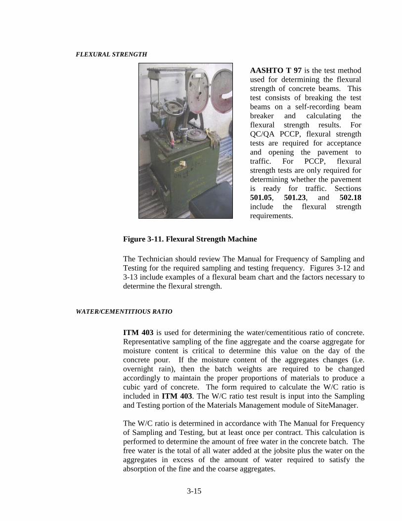
FLEXURAL STRENGTH
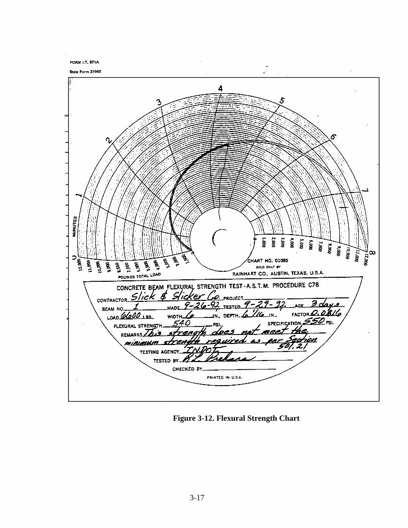
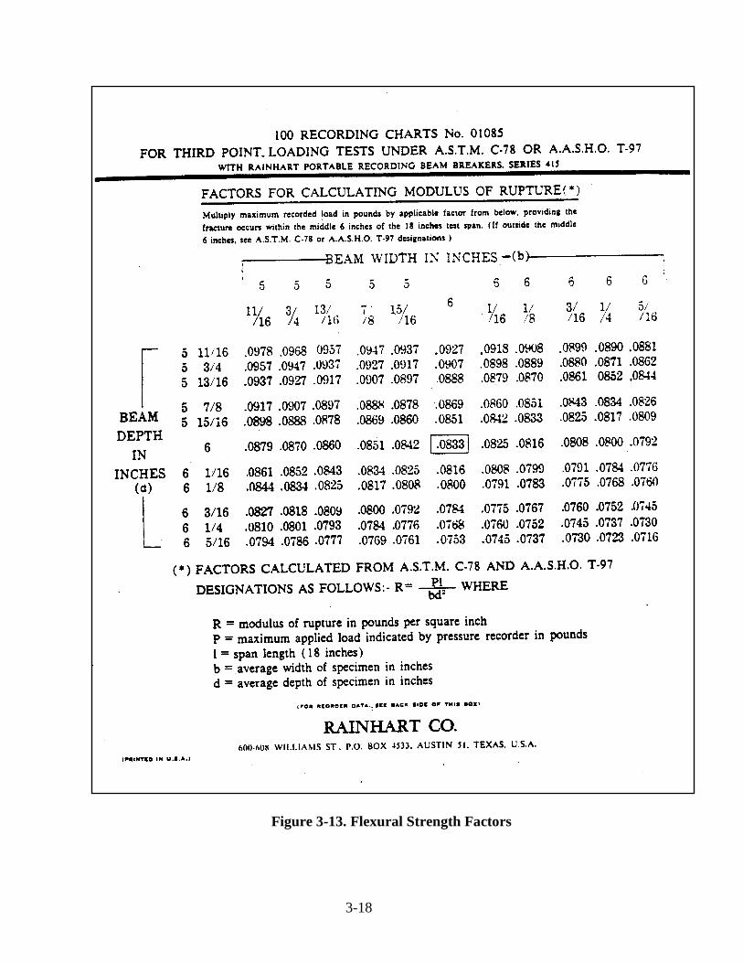
Figure 3-11. Flexural Strength Machine The Technician should review The Manual for Frequency of Sampling and Testing for the required sampling and testing frequency. Figures 3-12 and 3-13 include examples of a flexural beam chart and the factors necessary to determine the flexural strength.
WATER/CEMENTITIOUS RATIO
ITM 403 is used for determining the water/cementitious ratio of concrete. Representative sampling of the fine aggregate and the coarse aggregate for moisture content is critical to determine this value on the day of the concrete pour. If the moisture content of the aggregates changes (i.e. overnight rain), then the batch weights are required to be changed accordingly to maintain the proper proportions of materials to produce a cubic yard of concrete. The form required to calculate the W/C ratio is included in ITM 403. The W/C ratio test result is input into the Sampling and Testing portion of the Materials Management module of SiteManager. The W/C ratio is determined in accordance with The Manual for Frequency of Sampling and Testing, but at least once per contract. This calculation is performed to determine the amount of free water in the concrete batch. The free water is the total of all water added at the jobsite plus the water on the aggregates in excess of the amount of water required to satisfy the absorption of the fine and the coarse aggregates.
AASHTO T 97 is the test method used for determining the flexural strength of concrete beams. This test consists of breaking the test beams on a self-recording beam breaker and calculating the flexural strength results. For QC/QA PCCP, flexural strength tests are required for acceptance and opening the pavement to traffic. For PCCP, flexural strength tests are only required for determining whether the pavement is ready for traffic. Sections 501.05, 501.23, and 502.18 include the flexural strength requirements.

3-16
Free water is expressed in pounds of water per pound of cement and the ratio of the two is called the water to cementitious ratio. If pozzolans such as fly ash or GGBFS are included in the concrete mixture, then the weight of pozzolans is added to the cement weight for this calculation.
CURING CONCRETE
The proper curing method for concrete is essential during the early stages after the concrete is placed to allow the concrete to develop strength and durability. Proper curing is intended to allow the moisture in the concrete to evaporate slowly. Satisfactory curing is obtained by keeping the concrete cool and wet during the summer and not allowing the concrete to freeze during the winter months. Sections 501.20, 502.11, and 504.04 contain acceptable methods of protection from freezing and the proper curing methods.
FAILED MATERIALS
Pay items associated with QC/QA PCCP and PCCP require job control tests performed at the frequency included in the Manual for Frequency of Sampling and Testing. Test results that are not within the specification requirements require the Technician to inform the PE/PS of the deficiency as soon as possible. Depending on the property tested and the magnitude of the test failure, the PE/PS may have to suspend the paving operation until the Contractor demonstrates that a mixture complying with the specification requirements can be produced. Changes in additive rates of admixtures, changes in the amount of water added, or changes in the batch weights of the aggregates may be necessary to bring the subsequent tests into compliance. There is a failed materials process that is followed to determine whether the QC/QA PCCP or the PCCP associated with the failed test may remain in place with a reduction in compensation to the Contractor or if the newly constructed pavement requires removal and replacement. More information regarding the failed materials process is included in Chapter 10 of this manual.
3-17
Figure 3-12. Flexural Strength Chart
3-18
Figure 3-13. Flexural Strength Factors

4 Equipment Concrete Plants Central Mix Plant Ready-Mix Plant Delivery Equipment Paving Equipment Finishing Machine Spreader Slip-Form Pavers Hand Placement Finishing Equipment Tining Machine Vibrators Hand Equipment 10 ft Straightedge Tining Hand-Held Vibrators Saws Forms

4-1
CHAPTER FOUR: EQUIPMENT
The importance of having the proper equipment to do the job correctly and efficiently cannot be overstated, especially for construction of concrete pavements. This chapter discusses concrete equipment that has a profound effect on the quality of the final pavement.
CONCRETE PLANTS
INDOT categorizes concrete plants as central mix plants or ready-mix plants. Central mix plants, sometimes known as portable plants, are usually owned by the Contractor and constructed on a temporary basis on or adjacent to the project site. A central mix plant is usually used to produce concrete for a specific INDOT contract. When the contract is completed, the plant is disassembled and moved. Ready-mix plants are usually permanent installations owned by an entity other than the Contractor and serve many customers. Concrete plants are inspected and certified by the District Testing personnel. Ready-mix plants are inspected once a year. Central mix plants are inspected at the beginning of each construction season and whenever they are moved to a new location. A concrete plant is made up of several components. These include bins for the cement, fly ash, and GGBFS; weighing hoppers; scales for fine and coarse aggregates; admixture dispensers; and material conveyors. During the plant inspection, District Testing personnel verify that all scales are balanced and that all conveyors and hoppers are generally clean and free of foreign materials. Most concrete plants are operated by computers. The plant computer automatically drops or conveys each material into the hopper one at a time.
CENTRAL MIX PLANT
Central mix plants (Figure 4-1) are normally mobile units that are located at large quantity work sites. A central mix plant proportions and mixes the concrete in the plant. For QC/QA PCCP, the Contractor includes the central plant mixing requirements in the Quality Control Plan, QCP. For PCCP, central mix plant mixing is required to be no less than 60 seconds for each batch. When using a transit mixer for additional mixing, the mixing

4-2
time in the central mix plant may be reduced to approximately 30 seconds. The freshly mixed concrete is deposited into trucks for delivery. The delivery truck from a central mix plant does not need to provide any further mixing of the concrete, unless a transit mixer is used.
Figure 4-1. Central Mix Plant and Agitator Truck
READY-MIX PLANT
The second type of plant used is the ready-mix plant (Figure 4-2). Ready-mix plants batch the ingredients into a truck-mixer and the revolving drum on the truck mixes the ingredients.

4-3
Figure 4-2. Ready-Mix Plant
DELIVERY EQUIPMENT
Concrete is typically delivered to the job-site in transit mixer trucks, agitator trucks, or non-agitator trucks. All delivery trucks are required to comply with Sections 501, 502, and 508. Transit mixer trucks are designed to mix concrete at or on the way to the project site. For this reason, transit mixer trucks always have a water tank on board and a measuring device that is capable of controlling the amount of water that is added to the mix. When transit mixer trucks (Figure 4-3) are used, the following items are required to be checked by the Technician:
1) Manufacturer's rating plates are in place and legible 2) Revolution counters are operating properly 3) Mixing speed is as shown on the manufacturer’s rating plate,
and number of drum revolutions is in compliance with the equipment specifications.
4) Trucks are operated at or below their rated capacity

4-4
5) Discharge of the concrete is completed within 90 minutes of
mixing water, cement, and aggregates
Agitator and non-agitator trucks deliver concrete that has already been mixed. These trucks are not capable of mixing additional water and none may be added. Any water on board is for cleaning purposes only, not for mixing. When non-agitator trucks are used, the truck beds are required to be smooth, mortar tight metal containers capable of discharging the concrete at a satisfactorily controlled rate without segregation. The concrete is discharged from the bottom of the container. When the discharge is done by tilting, the container is required to be baffled to retard the flow of the mix. Covers are provided for protection of the concrete, when required. The discharge of the concrete is required to be completed within 30 minutes of mixing the water, cement, and aggregates when the concrete temperature is 90◦F or higher or 45 minutes when it is cooler. Regardless of the type of equipment used to deliver the concrete to the job site, the concrete is required to be uniformly mixed. Slump tests in addition to any required for acceptance may be taken by the Technician to verify uniformity of the mixture in accordance with Section 501.14 for QC/QA PCCP or Section 502.10 for PCCP. Additional testing will consist of slump tests taken in accordance with AASHTO T 119 at approximately the 1/4 and 3/4 points of a load. If the slumps differ by more than 1 in. when the average slump is 3 in. or less, or by more than 2 in. when the average slump is greater than 3 in., paving operations may be suspended while the mixing process is jointly reviewed and problems resolved by the Engineer and the Contractor.
4-5
Figure 4-3. Transit Mixer
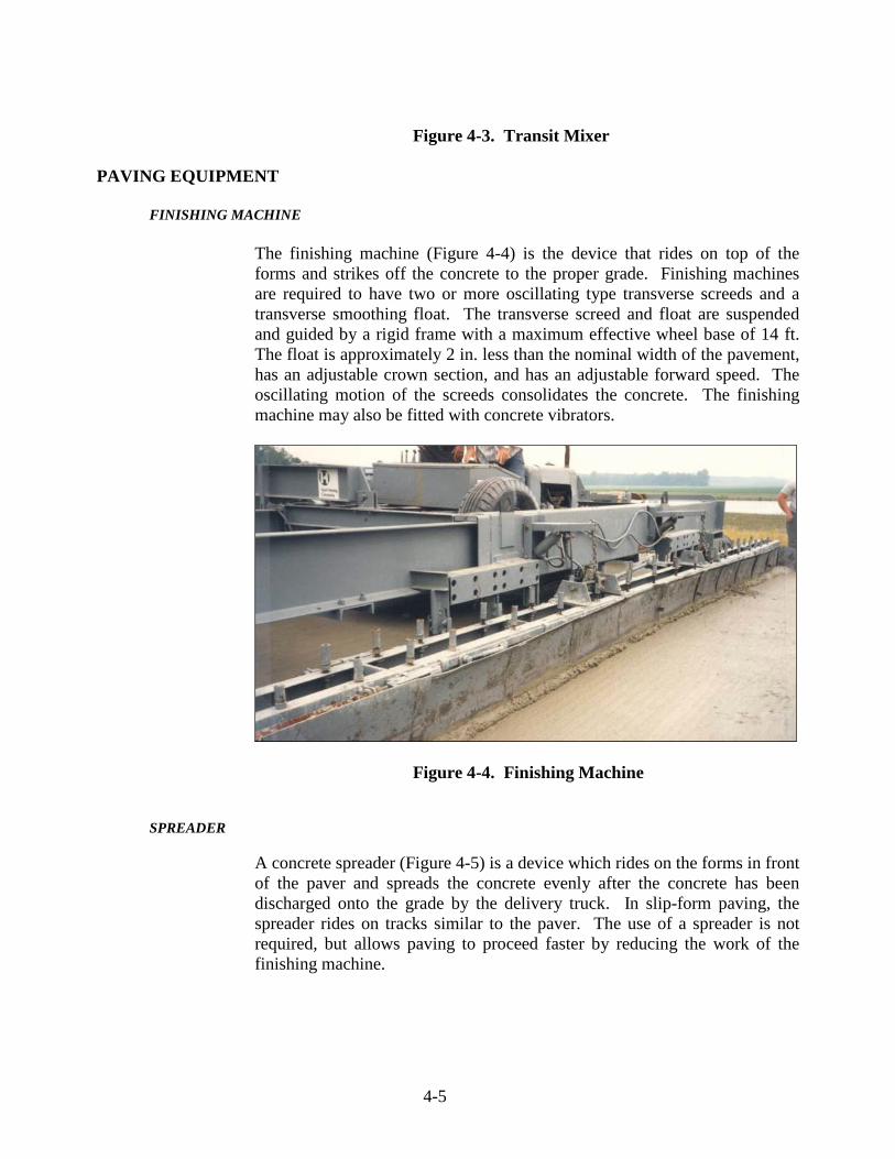
PAVING EQUIPMENT FINISHING MACHINE
The finishing machine (Figure 4-4) is the device that rides on top of the forms and strikes off the concrete to the proper grade. Finishing machines are required to have two or more oscillating type transverse screeds and a transverse smoothing float. The transverse screed and float are suspended and guided by a rigid frame with a maximum effective wheel base of 14 ft. The float is approximately 2 in. less than the nominal width of the pavement, has an adjustable crown section, and has an adjustable forward speed. The oscillating motion of the screeds consolidates the concrete. The finishing machine may also be fitted with concrete vibrators.
Figure 4-4. Finishing Machine
SPREADER
A concrete spreader (Figure 4-5) is a device which rides on the forms in front of the paver and spreads the concrete evenly after the concrete has been discharged onto the grade by the delivery truck. In slip-form paving, the spreader rides on tracks similar to the paver. The use of a spreader is not required, but allows paving to proceed faster by reducing the work of the finishing machine.

4-6
Figure 4-5. Concrete Spreader SLIP-FORM PAVERS
The slip-form paver (Figure 4-6) differs from the finishing machine in that the forms are mounted to the machine instead of being stationary. As the slip-form paver passes over the concrete, the concrete is spread, consolidated, and finished. Only a small amount of handwork is required after the concrete is placed. The slip-form paver rides on tracks and is usually controlled by a preset stringline. Sensors ride on the stringline and transmit line and grade information to the paver. Grade information is taken from the subbase or from a ski. The paver is required to be of sufficient weight and power to place the concrete at an adequate variable forward speed without transverse, longitudinal, or vertical instability. The paver is equipped with an automated steering and elevation control system. Slip-form paver requirements are included in Section 508.04(a).

4-7
Figure 4-6. Slip-Form Paver
Since the slip-form paver does all the forming of the pavement, the paver should be stopped only when absolutely necessary. When stopped, the paver may leave a slight imperfection in the pavement. All vibrators and tampers should be turned off immediately if the paver is stopped.
HAND PLACEMENT FINISHING EQUIPMENT
Hand placement finishing equipment is required to produce a concrete pavement with a uniform surface that is free of voids and meets the specified smoothness. The mechanical tube finisher, vibratory screed finisher, and mechanical bridge deck finisher are three types of hand placement finishing equipment that are used. The requirements for these types of hand placement finishing equipment are included in Section 508.04(c)3.
TINING MACHINE
The tining machine (Figure 4-7) is a device that automatically places grooves in the pavement using a texturing comb with steel tines spaced as specified. The grooves are placed in the pavement to provide additional skid resistance and eliminate hydroplaning. A uniform depth and alignment of the grooves in the concrete pavement without tearing the surface is required.
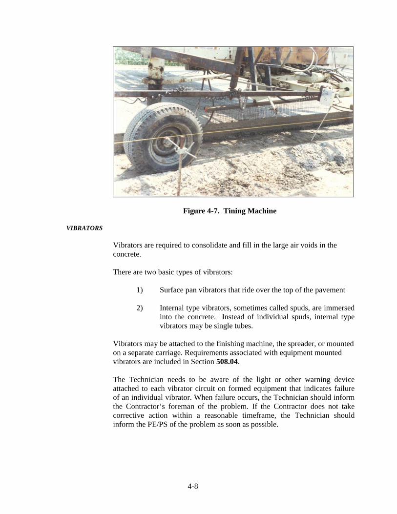
4-8
Figure 4-7. Tining Machine
VIBRATORS
Vibrators are required to consolidate and fill in the large air voids in the concrete.
There are two basic types of vibrators:
1) Surface pan vibrators that ride over the top of the pavement 2) Internal type vibrators, sometimes called spuds, are immersed
into the concrete. Instead of individual spuds, internal type vibrators may be single tubes.
Vibrators may be attached to the finishing machine, the spreader, or mounted on a separate carriage. Requirements associated with equipment mounted vibrators are included in Section 508.04. The Technician needs to be aware of the light or other warning device attached to each vibrator circuit on formed equipment that indicates failure of an individual vibrator. When failure occurs, the Technician should inform the Contractor’s foreman of the problem. If the Contractor does not take corrective action within a reasonable timeframe, the Technician should inform the PE/PS of the problem as soon as possible.

4-9
HAND EQUIPMENT
There are many hand tools available for concrete work and each has a specific use. The most common hand tools used are floats and trowels. A wide float of at least 5 ft in length and 6 in. in width is sometimes used to remove longitudinal imperfections in the pavement. Smaller floats may be used for other types of irregularities. Trowels are used to obtain very smooth surfaces as may be required on a sleeper slab, which is the support slab under a terminal joint. There is a wide assortment of small floats and trowels that a finisher may use along the edge of the pavement and at expansion and butt joints. These small floats may also be required for finishing around manholes, inlets, etc.
10 FOOT STRAIGHTEDGE
A 10 foot straightedge (Figure 4-8) with a handle 3 ft longer than half of the width of the pavement is used last to remove any longitudinal imperfections or surplus water from the surface.
Figure 4-8. 10 ft. Straightedge
TINING
Tining is the required method for final finishing. This procedure is normally done with a power driven tining device, which makes uniform transverse

4-10
grooves in the plastic concrete. A hand tool with steel tines (Figure 4-9) may be used on ramps, connections, and other miscellaneous areas where the mechanical tining equipment is not practical.
Figure 4-9. Steel Tine Hand Tool
HAND HELD VIBRATORS
Hand held vibrators (Figure 4-10) are required to have a head diameter of 1 ¼ to 2 ½ in. and be capable of 7000 to 10,800 impulses per minute in air. The vibrators may be used in areas where the machine mounted vibrators cannot reach such as at joints or around manholes and inlets.

4-11
Figure 4-10. Hand Held Vibrator SAWS
Self propelled single or gang-mounted concrete saws (Figure 4-11) are used to saw joints to the proper width and depth. These saws usually have small lights attached to them since much of the time they are used during night-time hours after the concrete has been poured. The required depth and alignment of the cuts is required to be done without damaging the concrete.
Figure 4-11. Self Propelled Concrete Saw

4-12
FORMS
When a standard finishing machine is used, forms are required to be set to the proper line and grade. Forms are a minimum of 10 ft in length and are required to have a depth of at least the pavement thickness. The base of the form is as wide as the depth of the form. The forms are fastened end to end and to the subgrade with at least three form pins and wedges and are required to be locked tightly to each other. The top face of the form is required to not vary from a true plane by more than 1/8 in. in 10 ft.

5 Setting Forms Form Fitness Subbase Support Form Setting Grade and Alignment

5-1
CHAPTER FIVE: SETTING FORMS
Since the quality and placement of the forms directly affects the quality of the pavement, subbase support, alignment, and general fitness of the forms is essential. The Technician needs to pay close attention to the allowable form tolerances and the methods of securing the forms to the subbase. Typically, forms are only used for miscellaneous pours at pavement gaps necessitated by traffic control requirements at intersections and driveways or locations where intersection or driveway geometrics make slip-form paving impractical. For QC/QA PCCP, neither the specifications nor the QCP requirements specifically address requirements for forms used in the paving operation. For PCCP, these requirements are included in Section 502.09. Although these requirements do not contractually apply to QC/QA PCCP, they represent best practices and the Technician should base inspection of the forms based on the PCCP requirements. In addition, even if the Contractor is employing a slip-form paver in its paving operation, there should be some forms available for the paving crew to utilize if edge slump problems develop.
FORM FITNESS
When paving is done with a finishing machine, the form setting operation is critical. As the forming process begins, each pavement form needs to be examined by the Technician. These forms have often been used for several years and may be in poor condition. The top edge of the forms represents the top surface of the pavement. If the form has a dip, the pavement will likely have a dip as well. Any form that varies by more than 1/8 in. in 10 ft along the top edge of the form or 1/4 in. in 10 ft along the face cannot be used (Figure 5-1). Also, forms that are no longer capable of being securely pinned and locked are not used. If the Contractor elects to repair rejected forms, they are required to be re-inspected before use. If deficient forms are found, the Technician should bring the matter to the attention of the Contractor’s paving foreman. If the Contractor fails to take the appropriate corrective action in a reasonable timeframe, the Technician needs to inform the PE/PS of the problem as soon as possible.

5-2
Figure 5-1. Allowable Form Variance SUBBASE SUPPORT
The subbase under the forms is required to be firm, constructed to grade, and make 100 % contact with the bottom of the form. Any variations in the form line are required to be corrected.
FORM SETTING
After the forms have been set to the proper line and grade, the subbase is required to be tamped along the inside and outside edges of the forms. Steel forms are required to have three form pins securing the form to the ground. Two of these pins are placed at the ends of the form. Wood forms require sufficient pins to prevent deflection of the forms while supporting the finishing equipment. Each form is locked to the next form and is required to be free from play or movement in any direction. All forms are cleaned and oiled before concrete is placed. The Technician is required to verify that all pin locks are secure.
GRADE AND ALIGNMENT
Before placing the concrete, form alignment and grade are compared to grade stakes. Any variation of 1/8 in. or more from the proper grade is required to be corrected. Likewise, any variation along the face of the forms of 1/4 in. or more also is corrected. The forms are checked for stability at this time. The Technician needs to inform the PE/PS as soon as possible if the Contractor fails to take corrective action in a reasonable timeframe.

5-3
If possible, forms should be prepared at least 500 ft ahead of concrete placement. If the material under the forms becomes unstable, the affected forms are required to be removed and the subbase repaired.

6 The Paving Operation Condition of Subbase Dowel Bars and Assemblies Mixing Concrete Weather Restrictions Placing Concrete Placing Reinforcing Steel Strike Off, Consolidation, and Finishing Floating Checking Finish and Surface Corrections Tining Edging Edge Slump Permanent Dates and Stations Curing Wet Burlap Wet Straw Waterproof Blankets Liquid Membrane Forming Compound

Protection from Rain Removal of Forms

6-1
CHAPTER SIX: THE PAVING OPERATION
Once the subbase has been checked for true line and grade, the paving operation may begin. The paving operation is a straightforward and systematic series of steps. This chapter covers each step in the paving operation and explains why each is necessary for a quality product. The following topics are discussed:
1) Checking the condition of the subbase 2) Checking placement of the tie bars and dowel bar
assemblies
3) Mixing and placing concrete
4) Finishing and curing concrete
5) Observing weather restrictions
In general, the following discussion applies to both QC/QA PCCP and PCCP. If any specifics only apply to one pavement type, it will be noted in the discussion.
CONDITION OF SUBBASE
The subbase is required to be maintained in a smooth and compacted condition up to the time paving begins. A dry subbase will absorb moisture from the concrete. Therefore, the subbase is required to be uniformly moist when the concrete is placed. Spraying water on the subbase ahead of the paving operation may be necessary (Figure 6-1). The Technician needs to ensure that the watering operation does not create mud or pools of water on the subbase. If either of these situations occurs, the Technician needs to discuss the problem with the Contractor paving foreman. If the problem persists, the Technician needs to inform the PE/PS as soon as possible. The subgrade or subbase shall be uniformly moist at the time of PCCP placement. Excessively dry subgrade or subbase shall be sprinkled with water.

6-2
Figure 6-1. Subbase Watering DOWEL BARS AND ASSEMBLIES
Dowel bars are smooth, epoxy coated, steel bars which are placed at all transverse joints to provide load transfer across the joints. Dowel bars allow the pavement to slide freely at the joint while expansion and contraction is occurring. When the dowel bars are used for expansion joints, the free end of each bar has an expansion tube attached to the bar. Generally, dowel bars are mounted in a welded wire basket referred to as a dowel bar assembly (Figure 6-2). This assembly holds all the dowel bars evenly and securely in place so they do not shift horizontally or vertically during the paving operation. The entire assembly is secured to the subbase with pins. Sufficient pins to secure the assemblies to the subbase must be provided.
Figure 6-2. Dowel Bar Assembly Placement

6-3
Dowel bars are required to be inspected for vertical and horizontal alignment before paving by the Technician. The recommended frequency for alignment verification is at least one for every 2000 feet of pavement. If the Technician witnesses movement of the dowel bar assemblies during the paving operation, a dowel bar check must be performed after the concrete has been placed. If this is required, the concrete is removed from the ends of each dowel bar on the assembly and each bar is checked. This procedure is done quickly because any correction is required to be made while the concrete is still plastic.
Figure 6-3. Dowel Bar Checker
Vertical alignment may be checked with a dowel bar checker (Figure 6-3). This device is first placed on the form or subbase next to the basket being checked, and the bubble is leveled to conform to the grade. Each dowel is then checked. If the bubble is not in the center, one leg of the checker is lifted until the bubble is in the center. If this correction is more than 1/4 inch, the dowel bar vertical alignment is required to be corrected.
Horizontal alignment is checked by measuring the distance from each end of the dowel to the form or string line and comparing the two measurements. If the measurements differ by more than 3/8 in., the horizontal alignment is required to be corrected. All dowel bar checks are documented by the Technician and these records are included in the contract file and final construction record. Prior to

6-4
placing concrete, individual dowel bars are coated with an approved material to break the bond with the concrete. Section 503 includes the specification requirements associated with dowel bar assemblies.
MIXING CONCRETE
Concrete may be mixed in any of the following ways:
1) On site mixers (these mixers are rarely used and are not discussed)
2) Central mix plants 3) Ready-mix plants using transit mixers
For QC/QA PCCP, the concrete mixing time will be in accordance with the Contractor’s QCP. If the Technician observes concrete associated with QC/QA PCCP being placed that does not appear to be uniformly mixed, slump tests as described in Chapter 3 of this manual and Section 501.14 should be performed. For PCCP, the concrete mixing time requirements are included in Section 502.10. When transit mixers are used, the Technician needs to witness the mixer drum complete the required number of revolutions prior to placement. Again, if the concrete does not appear to be mixed thoroughly at the time of placement, the Technician should perform slump tests as described in Chapter 3 of this manual and Section 502.10. Water may need to be added to transit mix concrete at the paving site. When concrete is delivered in transit mixers, additional water to increase the workability of a load may be added within 45 minutes of initial mixing. If the proper slump cannot be achieved within these time constraints, the Technician should notify the PE/PS as soon as possible. If adding water to the concrete trucks becomes routine, a correction is required to be made in the amount of water being added at the plant. The amount of water added is noted on the concrete tickets (Figure 6-4) for the concrete record.

6-5
Figure 6-4. Concrete Ticket

6-6
Concrete is required to be placed in a timely manner. The time requirements for mixes used for QC/QA PCCP are included in Section 501.14 and the requirements for mixes used for PCCP are included in Section 502.10. In order to enforce these requirements, the Technician needs to refer to the mixing time shown on the concrete ticket, recognize the type of truck used to haul the concrete, and be aware of the temperature of the concrete.
As temperatures vary, the workability of the concrete mix used in the pavement construction varies as well. The Contractor may elect to utilize chemical admixtures or other means to improve concrete workability. The Technician needs to be aware of the concrete mix design requirements in Section 501.04 for QC/QA PCCP or Section 502.03 for PCCP. In general, for QC/QA PCCP, new admixtures require new mix designs while changes in admixture dosage rates or a change in the source of a previously approved admixture do not require a new mix design. For PCCP, new admixtures, deletion of currently approved admixtures, as well as a change in source of a previously approved admixture require a new mix design. A change in the dosage rate of a previously approved admixture does not require a new mix design.
WEATHER RESTRICTIONS
Sufficient lighting is required for the concrete paving operations. If paving is performed during nighttime hours, lighting is used so that all operations are visible.
Weather limitations for QC/QA PCCP operations are included in Section 501.15. PCCP weather limitations are included in Section 502.11. PCCP shall not be placed on frozen subgrade or subbase. PCCP shall be placed when the ambient temperature is 35°F and above, unless procedures outlined in the QCP for lower temperatures are followed. PCCP operations shall be discontinued when the ambient temperature is descending and is 40°F or below. In order to enforce the applicable specification requirements, the Technician must be able to determine the air temperature during the paving operation, inspect the subbase to verify that aggregate material has not frozen, and after the concrete has been placed verify that the newly constructed pavement is not allowed to freeze prior to attaining strength necessary to open the pavement to traffic.
PLACING CONCRETE
For QC/QA PCCP, the requirements for placing concrete are included in Section 501.16. Similar requirements for PCCP are included in Section 502.12.

6-7
Sufficient equipment and material supplies are required to be kept on hand to allow for a continuous operation. The timing of concrete delivery is critical to the quality of the pavement, especially for slip-form paving. Every time that the paving train stops, there is potential for any number of deficiencies to be introduced in the pavement. Precautions may be necessary to prevent segregation of the concrete during the placement operation. Segregation occurs when fine and coarse aggregate particles within portions of the concrete mix are separated from each other. A segregated mix will appear non-uniform as there will be noticeable voids between coarse aggregate particles at some locations and other portions of the mix will only have fine aggregate particles visible. After placing, concrete should be handled as little as possible to minimize the risk of additional segregation. Any handling should be done by a machine or with a shovel instead of rakes. Equipment made of, or coated with, aluminum or aluminum alloy is not allowed to be used to place or transport concrete. All workers walking on the fresh concrete during placement are required to keep their footwear free of foreign material that may contaminate the fresh concrete.
Figure 6-5. Form Paving
Caution must be taken by all workers to not disturb joints and dowel bar assemblies. Machine mounted vibrators may have to be lifted to avoid joints, manhole castings, and other possible obstructions. Hand held vibrators are required to be used to consolidate the concrete in these areas as well as any other location that may not be accessible to the machine mounted vibrators. Consolidating the concrete against the faces of all forms and joints is important.

6-8
Vibrators should inserted in a fluid continuous motion and are not to be used in any one spot for more than a few seconds. Vibrators may never come into direct contact with the side forms, joint assemblies, or the subbase.
All castings associated with manholes and similar structures are required to be adjusted to the proper grade and surrounded with preformed joint material before paving begins. This step is very important as numerous pavement failures have been experienced at these locations. The Technician needs to communicate with the Contractor paving foreman if joint filler material is not used to isolate the casting from the pavement. If corrective action is not taken in a timely manner, the Technician needs to inform the PE/PS as soon as possible. Another element of the concrete paving operation that the Technician needs to watch is how the operation affects adjacent pavement which is to remain in place. Common problems that the Technician needs to look for include damage to adjacent pavement edges due to paving train equipment, damage to adjacent pavement from the newly constructed pavement joint sawing operation, as well as failure to remove concrete or other debris generated by the paving operation from adjacent pavement joints. If cement mortar or other incompressible materials are not removed from the joints in the adjacent pavement, the pavement cannot contract as intended and the concrete on either side of the joint may pop out. The Technician must report any damage to adjacent pavement to the PE/PS as soon as possible as the Contractor is responsible for repairing all damaged areas.
PLACING REINFORCING STEEL
The concrete is deposited on the subbase and spread by a mechanical spreader which also strikes the concrete off to the proper elevation. Concrete is kept in front of the strike off at all times to prevent depressions in the pavement.
Reinforcing tie bars for longitudinal joints may be inserted into the concrete automatically by the paver. The purpose for the tie bars is to ensure that all lanes in a pavement expand and contract in a unified manner. When paving two lanes at once, a straight tie bar is inserted every 3 ft along the longitudinal joint by the paver. If an adjacent lane is to be paved later, tie bars are inserted into the edge of the pavement at 30 degrees to the perpendicular and bent straight after the concrete has set (Figure 6-6). If more than one of the deformed bars in a panel break or become dislodged during straightening, all broken or dislodged bars are replaced with retrofitted tie bars.

6-9
Figure 6-6. Tie Bar Placement
All tie bars are required to be free from dirt, harmful rust, scale, paint, grease, oil, or anything else that may prevent the concrete from bonding to the steel.
STRIKE-OFF, CONSOLIDATION, AND FINISHING
The paving equipment is designed to properly strike off, consolidate, and finish the concrete accurately to the required elevation and cross section. For this to occur, a sufficient amount of concrete is required to be carried in front of the screed (Figure 6-7) so that the paver is cutting the concrete at all times. All voids and depressions are filled if this procedure is used. The operation is controlled to ensure that an excess of mortar is not carried to the surface. If segregated particles come to the surface in front of the screed, they are required to be mixed back into the unfinished concrete by hand and not allowed to be pushed to the grade ahead of the concrete.
6-10
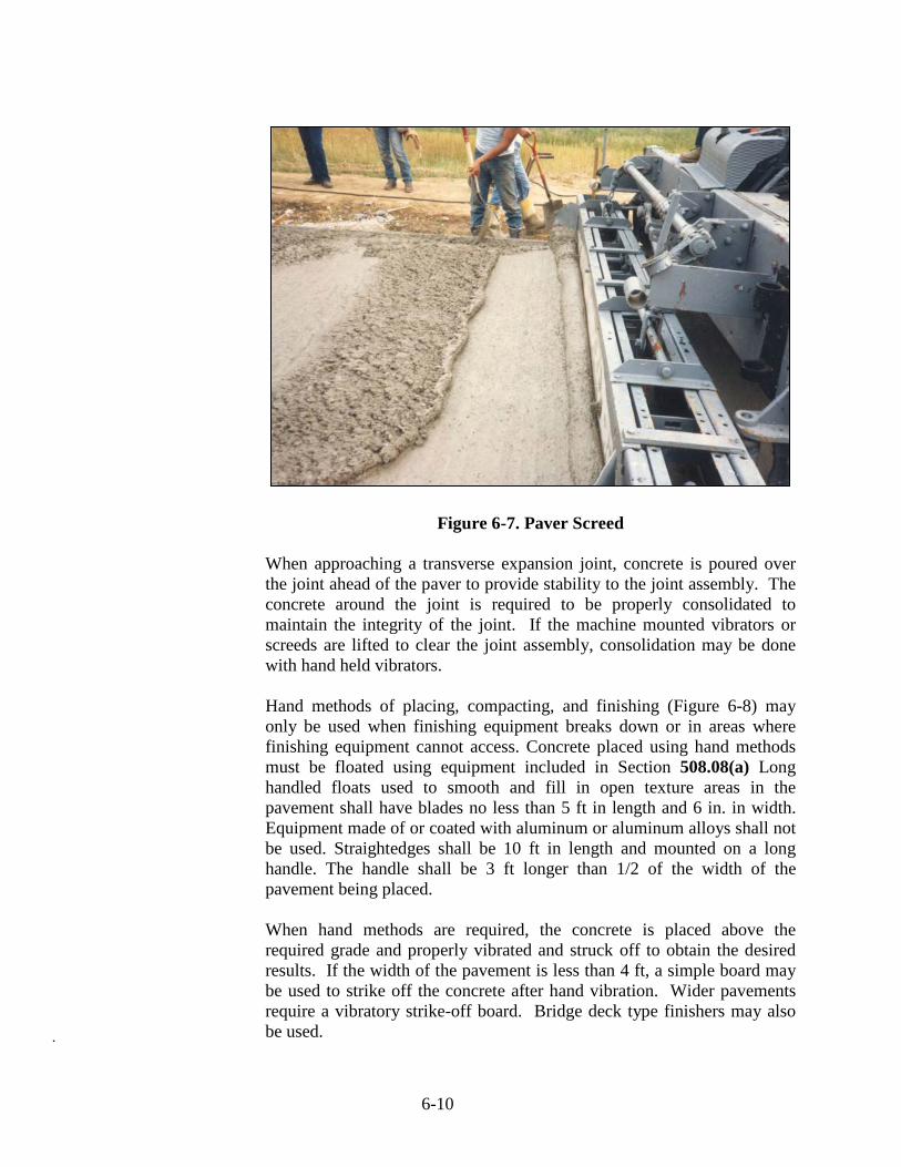
Figure 6-7. Paver Screed
When approaching a transverse expansion joint, concrete is poured over the joint ahead of the paver to provide stability to the joint assembly. The concrete around the joint is required to be properly consolidated to maintain the integrity of the joint. If the machine mounted vibrators or screeds are lifted to clear the joint assembly, consolidation may be done with hand held vibrators.
Hand methods of placing, compacting, and finishing (Figure 6-8) may only be used when finishing equipment breaks down or in areas where finishing equipment cannot access. Concrete placed using hand methods must be floated using equipment included in Section 508.08(a) Long handled floats used to smooth and fill in open texture areas in the pavement shall have blades no less than 5 ft in length and 6 in. in width. Equipment made of or coated with aluminum or aluminum alloys shall not be used. Straightedges shall be 10 ft in length and mounted on a long handle. The handle shall be 3 ft longer than 1/2 of the width of the pavement being placed.
When hand methods are required, the concrete is placed above the required grade and properly vibrated and struck off to obtain the desired results. If the width of the pavement is less than 4 ft, a simple board may be used to strike off the concrete after hand vibration. Wider pavements require a vibratory strike-off board. Bridge deck type finishers may also be used.
6-11
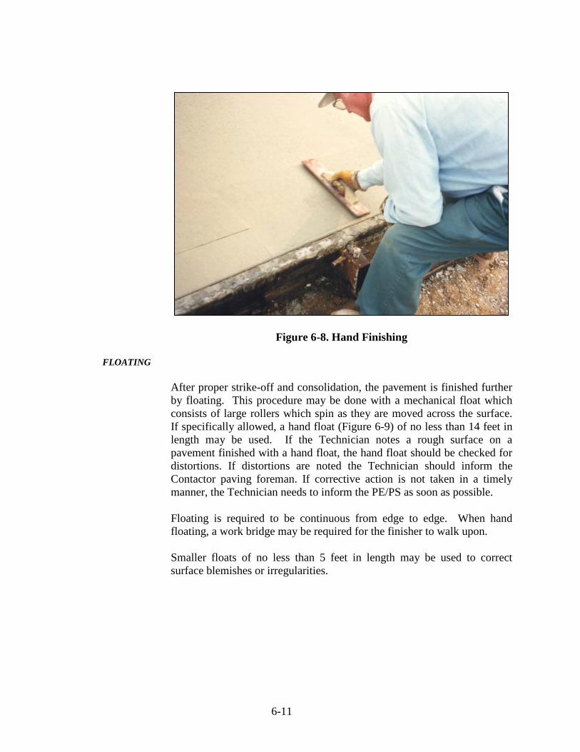
Figure 6-8. Hand Finishing FLOATING
After proper strike-off and consolidation, the pavement is finished further by floating. This procedure may be done with a mechanical float which consists of large rollers which spin as they are moved across the surface. If specifically allowed, a hand float (Figure 6-9) of no less than 14 feet in length may be used. If the Technician notes a rough surface on a pavement finished with a hand float, the hand float should be checked for distortions. If distortions are noted the Technician should inform the Contactor paving foreman. If corrective action is not taken in a timely manner, the Technician needs to inform the PE/PS as soon as possible.
Floating is required to be continuous from edge to edge. When hand floating, a work bridge may be required for the finisher to walk upon. Smaller floats of no less than 5 feet in length may be used to correct surface blemishes or irregularities.

6-12
Figure 6-9. Floating CHECKING FINISH AND SURFACE CORRECTIONS
When the final floating is complete, a long handled 10 ft straightedge is pulled across the concrete to remove any surface irregularities, surplus water, or inert material that may be present from the previous operations. This is the last opportunity to make corrections to the pavement and is an important process to assure pavement smoothness. Once the straight-edging is complete, an initial surface texture is created by dragging a double thickness of burlap or a piece of synthetic turf over the pavement. Now the pavement is ready for tining.
TINING
The final finish for the pavement is achieved by tining which is a process of placing grooves in the pavement to aid in skid resistance. This is done by a machine (Figure 6-10) using a comb with steel tines. Tining may be done manually on ramps, intersection radii, and other miscellaneous areas where machines cannot be utilized.

6-13
Figure 6-10. Machine Tining The grooves for tining are required to be between 3/16 and 1/8 in. in width and between 1/8 and 3/16 in. deep. Spacing of the tines is random and may be any of the following spaces:
1) 5/8 in. 10) 1 in. 19) 1½ in. 2) 1 in. 11) 3/4 in. 20) 7/8 in. 3) 7/8 in. 12) 7/8 in. 21) 3/4 in. 4) 5/8 in. 13) 1¾ in. 22) 7/8 in. 5) 1¼ in. 14) 7/8 in. 23) 1 in. 6) 3/4 in. 15) 3/8 in. 24) 7/8 in. 7) 1 in. 16) 1 in. 25) 1 in. 8) 1 in. 17) 1 in. 9) 1 in. 18) 1¼ in.
Timing is very important for the tining process (Figure 6-11). If done too soon, the grooves may be too deep or may close up. If done too late, the grooves may not be deep enough. When the latter occurs, grooves are required to be cut into the concrete by machine after the pavement hardens completely.

6-14
Figure 6-11. Tining Depth EDGING
All edges of slabs and formed joints are required to be rounded to the radius indicated in the plans. This procedure is accomplished using a finishing tool called an edger (Figure 6-12). Any tool marks left behind by the edger are removed before the burlap drag is used. All joints are checked with a straightedge to verify that no side of the joint is higher than the other. Corrections are required to be made immediately.
Figure 6-12. Hand Finishing Pavement Edge
6-15
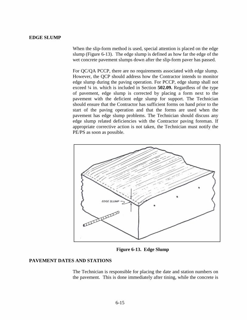
EDGE SLUMP
When the slip-form method is used, special attention is placed on the edge slump (Figure 6-13). The edge slump is defined as how far the edge of the wet concrete pavement slumps down after the slip-form paver has passed. For QC/QA PCCP, there are no requirements associated with edge slump. However, the QCP should address how the Contractor intends to monitor edge slump during the paving operation. For PCCP, edge slump shall not exceed ¼ in. which is included in Section 502.09. Regardless of the type of pavement, edge slump is corrected by placing a form next to the pavement with the deficient edge slump for support. The Technician should ensure that the Contractor has sufficient forms on hand prior to the start of the paving operation and that the forms are used when the pavement has edge slump problems. The Technician should discuss any edge slump related deficiencies with the Contractor paving foreman. If appropriate corrective action is not taken, the Technician must notify the PE/PS as soon as possible.
Figure 6-13. Edge Slump
PAVEMENT DATES AND STATIONS
The Technician is responsible for placing the date and station numbers on the pavement. This is done immediately after tining, while the concrete is

6-16
still plastic. This provides a permanent record of stationing along the pavement as well as a history of when the paving was performed. Cast iron dies are used to place the date and the plus station at the beginning of each days run. Full stations are also stamped every 500 ft (Figure 6-14).
Figure 6-14. Pavement Stationing
Station numbers are to be stamped on the right side of the pavement with the nearest digit approximately 8 in. from the edge of the pavement (Figure 6-15).
In the case of multiple lanes, the station numbers are placed along the outside edge of the pavement, readable from the same direction as the flow of traffic.

6-17
Figure 6-15. Pavement Stamp Location
CURING
Curing is as important to the integrity of the pavement as anything previously discussed. For proper curing, the pavement is required to retain moisture and be kept from freezing. Curing requirements are included in Section 504.04. Curing materials shall be applied to exposed surfaces and sides of newly placed PCCP within 30 minutes after the finishing operations have been completed, or as soon as marring of the concrete does not occur The Technician is responsible for monitoring the pavement throughout the required curing period. Depending on the curing method employed, the Technician may have to inspect the pavement on a daily or more frequent basis throughout the curing period to ensure that any covering media remain in place. Wind is the primary cause for displacement of covering media during the curing period. As soon as possible after a wind event, the Technician needs to check all pavement that is curing to verify that the covering media remain in place. For formed pavement, if the Contractor removes the forms within the curing period, the Technician needs to verify that the newly exposed pavement edges are cured throughout the remainder of the curing period.

6-18
If the pavement is not cured properly, its strength and durability will be compromised. This will result in additional maintenance and a reduced service life for the pavement. The methods used to retain moisture in the concrete include:
1) Wet burlap placed in two layers 2) Wet straw 3) Waterproof covers 4) Liquid membrane forming compound, commonly known as
curing compound
Figure 6-16. Liquid Membrane Forming Compound
The compound shall be applied in a continuous uniform film at a rate not less than 1 gal./150 sq ft. It shall be applied in two applications. If there is a danger of freezing during the curing period, the concrete pavement is further protected by a suitable covering of straw or blankets. During this period, the Technician must perform temperature checks under the covering at the pavement surface and recorded for the contract record. If the checks indicate that the pavement is being subjected to freezing temperatures, the Technician must inform the PE/PS as soon as possible.
PROTECTION FROM RAIN

6-19
Rain may be very detrimental to unhardened concrete pavement and measures are required to be taken by the Contractor to protect the pavement from this occurrence. The Contractor is required to have materials available at all times to protect the pavement in the event of an unexpected rain. If rain begins to fall, all available Contractor personnel are utilized to place a protective covering, usually plastic sheeting, on the pavement. Planks or forms are also required to be available to protect the edges of the pavement when slip-form paving. If the Technician believes that a rain event is about to occur while the paving operation is ongoing, the PE/PS should be contacted as soon as possible. The PE/PS and the Contractor Superintendent will be responsible for deciding whether a suspension of the paving operation due to the weather conditions is warranted.
REMOVAL OF FORMS
For QC/QA PCCP, requirements for form removal are included in Section 501.21. For PCCP, form removal requirements are included in Section 502.16. Forms may be removed as soon as the PCCP has hardened sufficiently to prevent edge spalling or other damage. Form pullers shall not be supported on the PCCP during form removal operations. The Technician needs to inspect the pavement edges while the forms are being removed or as soon as possible afterward and inform the PE/PS of any damage.
7 Pavement Joints Types of Joints Construction Joints D-1 Contraction Joints Longitudinal Joints Transverse Construction Joints Terminal Joints Expansion Joints Retro-fitted Tie Bars

7-1
CHAPTER SEVEN: PAVEMENT JOINTS __________________________________________
Pavement joints are vital to control concrete pavement cracking and movement. Without joints, most concrete pavements would be riddled with cracks within one or two years after placement. Water, ice, salt, and loads would eventually cause differential settlement and premature pavement failures. These same effects may be caused by incorrectly placed or poorly designed pavement joints. The Technician is responsible for inspecting all joints to avoid the problems associated with joint failure.
Pavement joint locations are typically not shown on the plans. Therefore, it is the responsibility of the Contractor to determine the joint locations. Forethought should be given to the design and placement of the pavement joints so that the end result is a properly functioning pavement system. Special attention is required at intersecting approaches, turn lanes and crossovers so that the joints required at these locations can be aligned with those in the mainline pavement. "Dead ending" of joints in the middle of adjacent slabs is avoided whenever possible to prevent a crack developing in the adjacent slab as an extension of the mainline joint. An example of a well planned joint design is shown in Figure 7-1. The joints in this diagram are continuous from edge of pavement to edge of pavement. Also, the joints in the mainline pavement are aligned to serve the joints in the adjoining pavements.
The following pavement joints and related materials are discussed:
1) Construction joints
2) D-1 contraction joints
3) Longitudinal joints 4) Transverse construction joints 5) Terminal joints 6) Expansion joints 7) Retrofitted tie bars
__________________________________________________________

7-2
Figure 7-1. Pavement Joint Layout
TYPES OF JOINTS
There are many types of joints used in the construction of concrete pavements but they all control the movement of the pavement and the associated cracking and/or differential settlement.
Longitudinal joints are constructed parallel to the center line, and transverse joints are constructed perpendicularly to the center line of the pavement. Understanding the use and function of the different types of joints is required in determining their placement.
CONSTRUCTION JOINTS Some longitudinal and transverse joints are placed in the pavement in order to control cracking as discussed above. Other longitudinal and transverse joints are required because of limitations on the construction operation and the construction equipment. These joints are referred to as construction joints. For most contracts, it is not possible for the Contractor

7-3
to produce and deliver sufficient concrete to construct all the pavement required for a project in a single day. Therefore, at the end of each day a transverse construction joint is constructed from which the paving operation will begin the following work day. Also, in many situations a project will require that a Contractor construct a pavement that is wider than the available paving equipment can produce. In these situations, a longitudinal construction joint is constructed along a lane line over the entire length of the pavement. The lane adjacent to this longitudinal construction joint will be built at a later date.
D-1 CONTRACTION JOINTS
D-1 contraction joint requirements are included in Section 503.03(a). Typically, a contraction joint is a sawed transverse joint normally placed at a spacing shown on the plans to control cracking due to pavement contraction caused by concrete shrinkage and temperature fluctuations. The sawed contraction joint shall not exceed 18 ft.
A dowel bar assembly (Figure 7-2), commonly called a basket, is secured to the subbase before paving at the location of each contraction joint. The Technician is responsible for verifying that the dowel bar assemblies are installed at the appropriate spacing. The steel bars of this assembly, or dowel bars, are large and, once incorporated into the concrete pavement, transfer the vehicular load from one slab to another, eliminating differential settlement known as faulting at the joint.
Figure 7-2. Dowel Bar Assemblies

7-4
The location of the center of each dowel bar assembly is marked by Contractor personnel outside of the form/slab line so that the dowel bar assembly may be located once the pavement is in place. This is necessary so that the joint saw cut will be made in the proper location. These markings must be maintained during and after the paving operation because the markings may easily become disturbed during construction. The Technician is also required to monitor the locations of the tie-bar reinforcing steel to ensure that the tie bars do not interfere with the operation of the D-1 joint. Tie bars placed within the limits of a dowel bar assembly must be adjusted longitudinally so that they do not hamper the movement designed into the joint. The longitudinal adjustment required is seldom more that 1 ft (Figure 7-4) and is accomplished by installing a retrofitted tie-bar.
Figure 7-3. Tie Bar Adjustment at Dowel Bar Assembly After paving, the previously designated centerline locations of the dowel bar assemblies are utilized to mark the joint saw cut on the pavement and the initial saw cut is made for the joint. Timing is critical when making this saw cut on contraction joints. If sawed too soon, the joint spalls and ravels. If sawed too late, the pavement may have already cracked randomly. For this reason, the sawing of joints often starts within 2 to 12 hours of the time of concrete placement, depending upon the ambient/material temperature, humidity, and wind conditions. The initial sawing of a pavement continues, night and day, regardless of weather conditions until complete. If random cracking is observed ahead of current sawing operations, the sawing operation is advanced until the random cracking is controlled. The joint is required to be sawed straight for the full depth, width, and length of the joint. The Technician is responsible for checking these requirements. Because of the importance of

7-5
the sawing operation, the Technician should not hesitate to contact the PE/PS with any questions or if any problems arise.
If slurry created by the sawing operation settles in the saw cut, this material is required to be flushed with high pressure water to remove the slurry from the entire depth of the joint. Care is taken not to damage the pavement while flushing because the concrete is still "green" and vulnerable to damage from excessive force. If the slurry is not removed from the joint, this material hardens and the joint is required to be re-sawed.
Just prior to sealing, the joint is blown with a jet of compressed air, or otherwise cleaned, to remove all foreign material and prepare the joint faces for the sealer. It is important that the joint faces are dry and clean prior to application of the joint sealer. Some joint seals require installation of a backer rod prior to application of the seal material. The installed depth of the backer rod and thickness of joint sealer is critical for a properly functioning joint. The depth at which the backer rod is set establishes the bottom of the joint sealer. The depth and thickness at which the sealer is installed is required to be monitored by the Technician. The surface of the sealer is required to be below the surface of the pavement so that traffic does not damage or pull out the seal material. Also, the sealer thickness is critical so that the elasticity of the sealer is maintained. This is an instance where more is not better. Section 503.05 and Standard Drawing 503-CCPJ-06 include requirements for joint seals. The joint seal integrity plays an important role in the performance and service life of the concrete pavement. The seal is the only barrier that prevents water and de-icing chemicals from entering the pavement structure. This is especially important for joints located near the low point of sag vertical curves. If a joint seal fails, water and de-icing chemicals can saturate the joint. Over time concrete in the joint will deteriorate, usually beginning below the pavement surface and working its way up. This phenomenon has resulted in increased pavement maintenance costs and reduced pavement service lives. Therefore, the Technician must be diligent while inspecting the joint sawing and sealing operations to ensure that the seal material will perform as intended.

7-6
All joints are required to be sealed prior to opening a section of pavement to any traffic, other than construction traffic, or before the end of the current construction season. The steps in constructing a D-1 contraction joint (Figure 7-4) include the following:
1) A 1/8 in. cut is made in the pavement for the full width and proper depth of the joint.
2) The final cut is made to prepare the joint for the backer rod
and sealant. 3) The joint is thoroughly cleaned and a backer rod is installed
at the proper depth.
4) The sealant is installed to the proper depth and thickness.
Figure 7-4. D-1 Contraction Joint

7-7
LONGITUDINAL JOINTS
A longitudinal joint (Figure 7-5) is required in all pavements wider than 16 feet. If two adjacent lanes are poured at the same time, a longitudinal joint is sawed along the lane line between the lanes.
Figure 7-5. Longitudinal Joint Tie bars between lanes placed at the same time are placed perpendicular to the longitudinal joint and parallel to the underlying subbase. Tie bars shall be machine placed during paving or secured with chairs prior to paving. When tie bars are required along the form line or the edge of a slip-formed lane, bent bars are used. Bent bars are tie bars bent at a 60° angle. These bars are straightened after the concrete sets so that they extend into an adjacent lane. .
Figure 7-6. Tie-Bar for Longitudinal Joint

7-8
Some longitudinal joints require the use of a keyway with no tie bars. Keyways (Figure 7-7) may be trapezoidal or semi-circular in shape. They are used when an adjacent pavement is expected to move independently and the two pavements cannot be tied together. The keyway prevents any differential settlement of either pavement slab.
Figure 7-7. Keyway Joints Longitudinal sawed joints are cut with a power concrete saw concurrently with the contraction joints. Requirements associated with longitudinal joints are included in Section 503.03(a). Requirements associated with longitudinal construction joints are included in Section 503.03(d). Standard Drawing 503-CCPJ-03 illustrates the joint seal requirements. Only one sawcut is required for longitudinal joints, instead of the two associated with D-1 contraction joints. As is the case with the sawing and sealing operation for D-1 contraction joints, it is important that the sawcut edges are clean and dry prior to applying the joint seal material. Longitudinal joint seals that have failed have also resulted in the same type of pavement distresses and reduced service lives as was discussed earlier in this chapter for joint seals for D-1 contraction joints.
TRANSVERSE CONSTRUCTION JOINTS
Requirements associated with transverse construction joints are found in Section 503.03(c) and Standard Drawing 503-CCPJ-05. A transverse construction joint is used when the paving operation is interrupted for longer than the maximum allowable time. These joints are commonly used at the end of the paving operation each day and may be retro-fitted to tie an existing slab to a new pavement. Transverse

7-9
construction joints are required to be located as noted in Section 503.03(c) from an adjacent D-1 contraction joint. Spacing of the tie bars in the transverse construction joint is required to be as shown on Standard Drawing 503-CCPJ-05. The tie bars are required to be epoxy coated and inserted through a header board set to the proper line and grade. Care is taken to assure that the bars are placed parallel to the subbase and the centerline. If the transverse construction joint is retro-fitted, the existing pavement is drilled to accept the epoxy coated tie bars. The diameter of the drilled hole is required to be as recommended by the manufacturer of the approved chemical anchor system being used.
TERMINAL JOINTS
A terminal joint (Figure 7-8) is placed where a concrete pavement ends at a bridge or similar structure. A 2 ft gap is left between the end of the pavement and the beginning of the reinforced concrete bridge approach. The ends of the pavement and the reinforced concrete bridge approach are placed on a sleeper slab that has been previously poured. The sleeper slab is finished smooth and allowed to cure. A polyethylene sheet is placed over the slab prior to placing the pavement or reinforced concrete bridge approach. This sheet is a bond breaker, allowing the pavement and reinforced concrete bridge approach to move freely over the sleeper slab as they expand and contract.
The gap between the pavement and the reinforced concrete bridge approach is filled with HMA intermediate and surface mixtures to complete the joint.

7-10
Figure 7-8. Terminal Joint
EXPANSION JOINTS Requirements associated with expansion joints are included in Section 503.03(f). Expansion joints shall be constructed at the locations shown on the plans and shall consist of joint filler. The joint filler shall be shaped to the subgrade, parallel to the surface, and be full width of the pavement. Damaged or repaired joint filler shall not be used. The joint filler shall be held in a position which is normal to the surface. The purpose of an expansion joint is to account for expansion of the concrete pavement. If expansion joints are not utilized, the concrete pavement would essentially crush itself as it expands.
RETRO-FITTED TIE BARS
When new pavement is to be tied to an existing pavement, tie bars are used to tie the pavements together. The requirements associated with retro-fitted tie bars are included in Section 503.03(g). Retrofitted tie bars shall be secured at right angles to the pavement with a chemical anchor system in accordance with the manufacturer’s recommendation. The chemical anchor system shall be injected to the back of the hole to eliminate air pockets prior to inserting the bar. The quantity of material injected shall be sufficient to disperse the material along the entire length of the bar and completely fill the annular space. After the anchor system has been injected, the bar shall be fully inserted using a back-and-forth twisting motion, leaving the proper length exposed. Once the adjacent pavement has been poured, the joint is sawed and sealed the same procedure as required for a construction joint.

8 Miscellaneous Pavement Details and Requirements
Ear Construction Pavement Smoothness Protection of Pavement Opening Pavement to Traffic Construction Vehicles Non-Construction Vehicles Pavement Thickness Coring Core Measurements Deficient Pavement Thickness Method of Measurement and Basis of Payment

8-1
CHAPTER EIGHT: MISCELLANEOUS PAVEMENT DETAILS AND REQUIREMENTS
In this chapter the following items are discussed:
1) Ear construction which prevents the tips of concrete tapers from breaking up
2) Pavement smoothness and thickness tolerances and how they effect payment to the Contractor
3) Protection of pavement 4) Opening to traffic 5) Removal and replacement of deficient pavement 6) Methods of measurement for final payment
EAR CONSTRUCTION
Ear construction (Standard Drawings E605-ERCN-01 and E605-ERCN-01) is required wherever concrete pavement tapers to or from a point. Tapers are usually utilized at ramps, turn lanes, and other facilities designed to allow traffic to accelerate or decelerate prior to making a turning movement. If the concrete was actually constructed so that it would taper to a point, the concrete would shear off under the weight of traffic. Ear construction utilizes a minimum width of 1 ft with reinforcing steel to prevent shear failure.
Ear construction uses an expansion joint to isolate it from the remainder of the tapered pavement. It is also tied to the adjacent mainline pavement so that it moves in unison with the mainline.
PAVEMENT SMOOTHNESS
After the concrete has cured enough to permit testing, the profile of the pavement is required to be checked for smoothness. All pavement is to be checked for smoothness before opening to traffic or before work is suspended for the winter.

8-2
Smoothness is checked by one of three methods:
1) A profilograph (Figure 8-1), or an approved equivalent, is used on all mainline QC/QA PCCP meeting the requirements included in Section 501.25(a). When a profilograph is used, each pavement lane is divided into smoothness sections over which a profile index will be determined.
Figure 8-1. Profilograph
2) A 16 ft straightedge is used on all PCCP pavements and on QC/QA PCCP pavements that meet the requirements contained in Section 501.25(b).
3) A 10 ft straightedge is used on transverse slopes,
approaches, and crossovers.
Profile smoothness is checked 3 ft from, and parallel to, the outside edge of each lane up to 12 ft wide. Lanes wider than 12 feet are checked 3 ft from both edges. Any liquid membrane forming compound removed during the straightedge operation should be replaced immediately. When correction is needed, a groove type cutter is used to grind the pavement to the proper smoothness while maintaining the required skid resistance.

8-3
The required surface tolerances for PCCP are:
1) 16 ft straightedge – 1/4 in. or less 2) 10 ft straightedge – 1/8 in. or less
The required surface tolerances for QC/QA PCCP are:
1) Profilograph – 3.80 in./0.1 mile profile index or less 2) 16 ft straightedge – 1/4 in. or less 3) 10 ft straightedge – 1/8 in. or less
In addition to the requirements for the profile index for the profilogragh, any area having a high or low point deviation in excess of 0.3 in. is required to be corrected. Verifying profilgraph measurements are taken only in the smoothness section where grinding has been conducted to reduce the profile index. Additional information related to corrective action for smoothness can be found in Chapter 10 of this manual.
PROTECTION OF PAVEMENT
Until final acceptance of the new pavement, the Contractor is responsible for protecting the pavement against damage. This protection may require barricades, watchmen, lights, crossovers, or a number of other measures. All damaged pavement prior to final acceptance is required to be repaired or replaced.
OPENING PAVEMENT TO TRAFFIC
CONSTRUCTION VEHICLES
Newly constructed pavement shall not be subjected to loading from Contractor equipment or vehicles until the requirements included in Section 501.23(a) are met for QC/QA PCCP or Section 502.18(a) for PCCP. Construction vehicles or equipment will be allowed on the PCCP after 10 days or when flexural tests indicate a modulus of rupture of 550 psi or greater. ITM 402 may be used as an alternate method to determine the flexural strength However, saws required to cut pavement joints are allowed on the pavement prior to the applicable above noted requirements are met. The Technician must inform the PE/PS as soon as possible if Contractor vehicles or equipment utilizes the pavement prior to the applicable requirements are met.

8-4
NON-CONSTRUCTION VEHICLES
Newly constructed pavement shall not be subjected to traffic loading until the requirements associated with Section 501.23(b) are met for QC/QA PCCP or Section 502.18(b) for PCCP. PCCP may be opened to traffic after 14 days. The PCCP may be opened earlier if test beams or ITM 402 indicate a modulus of rupture of 550 psi or greater. The minimum frequency for casting beams for determination of the modulus of rupture is included in the Manual for Frequency of Sampling and Testing. The Technician should discuss with the PE/PS whether additional beams should be cast in situations where opening the newly constructed pavement to traffic as early as possible is necessary to maintain the required contract schedule. If the test beams do not indicate a minimum modulus of rupture of 550 psi within 14 calendar days of pavement construction, the Technician needs notify the PE/PS as soon as possible. Again, if the Technician becomes aware that non-construction vehicles are using the newly constructed pavement prior to the applicable requirements are met, the PE/PS needs to be notified as soon as possible.
PAVEMENT THICKNESS
Concrete pavement is required to be constructed to the thickness specified in the contract. Before final acceptance, the actual thickness as constructed is determined from the measurement of cores drilled from the pavement.
CORING
Pavement thickness at designated locations throughout the contract is determined by obtaining cores after corrective grinding (Figure 8-2) has been performed. The Contractor obtains these cores at the locations determined by the Engineer in accordance with ITM 802. Cores are taken for the full depth of the pavement thickness and are required to be 4 in. in diameter. The coring operation is witnessed by the Engineer who identifies, marks, and takes immediate custody of the cores. Sections 501.26 and 502.21 include limitations on locations where cores may be taken for QC/QA PCCP and PCCP, respectively. Cores shall not be taken within 6 in. of the edge of pavement, within 3 in. of longitudinal joints, within 2 ft of D-1 contraction joints, or within 5 ft of a transverse construction joint.

8-5
The required core frequencies for QC/QA PCCP and PCCP can be found in the Manual for Frequency of Sampling and Testing. After the coring operation is complete, the Technician needs to verify that the core holes shall be filled with PCC or rapid setting patch material within 24 h of drilling. This is important as it reduces the amount of water that enters the pavement structure.
Figure 8-2. Concrete Coring CORE MEASUREMENTS
The length of each core is determined in accordance with ITM 404. The Technician must take care when following ITM 404 procedures. The paste associated with the concrete can attach itself to the aggregate from the underlying subbase. This can make it difficult to perform the core length measurement.
DEFICIENT PAVEMENT THICKNESS

8-6
For QC/QA PCCP, the core lengths for the cores within a sublot are averaged and the average is compared to the pavement thickness required by the contract. A pay factor is determined in accordance with Section 501.28(c). Sublots with an average core length which is less than the required pavement thickness will have a pay factor that is less than 1.00. The pay factor is applied to the unit price and sublot quantity resulting in a negative quality assurance adjustment. More information regarding pay factors as well as lots and sublots is included in Chapter 10 of this manual. For PCCP, if a core measurement reveals that the pavement is more than 0.5 in. deficient in thickness, additional cores are required in accordance with Section 502.21. These additional cores are required to determine the limits of the pavement that has deficient thickness. Sections 502.21(d) and 502.21(e) include discussions regarding non-payment or replacement of pavement found to have deficient thickness. In summary, construction of pavements with deficient thickness results in either a reduction in pay due the Contractor or may require the Contractor to remove and replace the thin pavement. If removal and replacement of pavement is required, the Technician will be responsible for all job control testing and inspection for the new pavement as was the case for the original construction.
METHOD OF MEASUREMENT AND BASIS OF PAYMENT
Concrete pavement is measured and paid for by the square yard. The width is taken from the applicable typical cross sections on the plans and the length is measured along the center line of each lane or ramp. Paving exceptions which place gaps in the pavement are not measured. Payment for concrete pavement includes all materials not otherwise indicated in the contract as a pay item. Retrofitted tie bars are paid separately for each bar, unless the bars are necessary to repair pavement that was damaged by the Contractor in one of the manners discussed in Section 503.08. Contraction, expansion, and terminal joints are measured and paid for by the linear foot. The cost of dowels, dowel bar assemblies, backer rod, joint sealants, and all necessary incidentals are included in the cost of the D-1 contraction joints. The cost of the sleeper slab, reinforcing steel, bond breaker, and HMA mixtures are included in the cost of the terminal joint.

9 Concrete Pavement Patching Materials Concrete Mix Design Concrete Mix Criteria Trial Batch Demonstration of CMDS Acceptance Removal of Concrete Partial Depth Patches Full Depth Patches Placement of Patching Materials Partial Depth Patches Full Depth Patches Curing/Opening to Traffic Method of Measurement Basis of Payment

9-1
CHAPTER NINE: PORTLAND CEMENT CONCRETE PAVEMENT PATCHING _______________________________________
Portland cement concrete pavement patching consists of the removal and replacement of unsound concrete, either full depth or partial depth. The following items are discussed in this chapter:
1) Materials and the composition of patching concrete 2) Removal of unsound concrete
3) Preparation of the patch for placement of the new concrete
4) Placement of the patching components
5) Temperature and curing requirements
6) Method of measurement
7) Basis of payment
MATERIALS
Materials used for PCCP patching include:
1) Dowel bars
2) Fine aggregate, size No. 23
3) Coarse aggregate size No. 8, Class AP
4) Coarse aggregate size No. 11, Class A or Higher
5) Portland cement
6) Water
7) Calcium chloride, Type L
8) Admixtures

9-2
9) Chemical anchor systems
All of the materials are required to meet the requirements of Section 506, Section 900, and the Approved List for materials. The Technician needs to look through the Contract Information Book, CIB, to verify that there are no special provisions included in the contract to modify the requirements of Section 506. One potential modification to the Section 506 requirements involves contracts that include long patches. Concrete mixes that meet Section 506 material requirements are very aggressive and set up very quickly. When such a mix is used in a long patch, the concrete becomes very difficult to work with for the Contractor and often is prone to random cracks shortly after construction. Therefore, in situations where long patches are required, the contract may require a less aggressive mix in an effort to improve the workability for the Contractor and minimize random cracking.
CONCRETE MIX DESIGN
The Concrete Mix Design process is discussed in Section 506.03. The process involves the submittal of a CMDS, followed by a trial batch, and ending with the submittal of the proposed CMDP.
Section 506.03 includes provisions for the following modifications to the CMDP—change in materials, adjustments to materials, and other adjustments. A change in materials requires a new CMDS. The Contractor then has the option of performing a new trial batch or using the first day of production as the trial batch at the Contractor’s risk. An adjustment to a material requires a new CMDS, but no trial batch or first day production verification. Other adjustments as defined in Section 506.03 do not require a new CMDS and no DTE notification or approval is required. If a new CMDS is required, DTE approval is required prior to performance of a trial batch or first production day verification. In addition to the process described above, Section 506.03 allows the Contractor to submit a previously approved CMDP to the DTE for approval. Once approval is granted by the DTE, the Contractor is free to use the CMDP in the same manner as would have been the case if it had been approved after submittal of a CMDS and performance of a trial batch.
CONCRETE MIX CRITERIA
The concrete mix criteria requirements are included in Section 506.04. The primary difference in patching mixes compared to pavement mixtures

9-3
is that patching mixes include calcium chloride or additional cement to gain strength much sooner than concrete mixes used in new concrete pavement construction applications. This is necessary because it is normally required to open a newly constructed patched pavement within a few hours instead of days or longer as usually available for mixtures associated with new pavement construction.
TRIAL BATCH DEMONSTRATION OF CMDS
Trial batch requirements are included in Section 506.05. The Technician will be involved in the performance of side by side sampling and testing along with Contractor personnel as is the case for trial batches associated with concrete pavement mixtures. This testing will be used to verify that the CMDS is able to produce a mixture that meets Section 506.04 requirements. If the test results confirm the required performance of the CMDS, then the Technician will forward his or her test results to the Contractor for submittal to the DTE seeking approval of the resulting CMDP. The trial batch may be produced prior to construction in a laboratory, at the plant, or at the project site prior to the first day of production.
When the production from the first day is used as a trial batch, production may continue until the flexural strength tests are completed. If the 24 hour or 3 day flexural strength tests fail to meet the requirements of Section 506.04, production is required to be stopped and a new CMDS is developed and submitted. The patches associated with the failing test results will be subject to the failed materials process which is explained in more detail in Chapter 10 of this manual.
ACCEPTANCE Job control testing, including air, slump or flexural strength, is conducted by the Technician in accordance with Section 506 and the Manual for Frequency of Sampling and Testing. When a test indicates that the material does not meet contract requirements, the Technician must notify the PE/PS who is responsible for notifying the Contractor. Rounding of test results is required to be in accordance with Section 109.01(a).
REMOVAL OF CONCRETE
There are two types of concrete patches—partial depth and full depth. The contract plans will include information related to the locations and types of patching required in the contract.

9-4
PARTIAL DEPTH PATCHES
The requirements associated with removal of existing concrete for a partial depth patch are in Section 506.07(a). The saw cut shall be a minimum of 1 in., to a maximum of 3 in. Removal of all unsound concrete to a minimum depth of 1 in. shall be by hand chipping tools or hand held mechanically driven equipment. Mechanical hammers shall not be heavier than a nominal 45 lb class. Mechanically driven tools shall be operated at a maximum angle of 45° from the PCCP surface. If the saw cut face is damaged, a parallel saw cut 1 in. outside the initial saw cut shall be made and the concrete in this area shall be removed by hand chipping. The Technician’s priorities while inspecting this work are as follows:
1) Ensure all unsound concrete at the patch location is removed
2) Verify whether concrete removal requires full depth patch
3) Watch for reinforcing steel exposed during removal operation
In most cases, patches are located where the concrete pavement shows a distress of some type at the surface. The decision to patch the pavement is usually made based on this surface distress. However, the pavement distress may cover a larger surface area than indicated by the distress at the surface. Also, the surface distress does not indicate the depth of damage to the existing pavement. Therefore, as the concrete removal operation is ongoing, it always necessary to check the pavement for sound concrete. This can be done by dragging a chain or dropping a reinforcing bar on the remaining pavement. Sound concrete will produce what can be described as a solid sound while unsound concrete will produce a thud or a hollow sound when tested. It is important that upon the completion of the concrete removal operation that only sound concrete remains. For partial depth patching, the Technician needs to ensure that the depth of concrete removal is within the allowable range. If less than minimum depth is removed, the concrete used in the patch will pop out. If the removal depth exceeds the maximum, there will be insufficient sound original concrete over the contraction joint dowel bars to facilitate load transfer. Eventually, the original concrete over the dowel bar will fail and the overlying partial depth patch will pop out. If wire mesh reinforcing is exposed during the concrete removal operation, the exposed portion must be removed. If reinforcing bars are exposed, a partial depth patch will not work at this location and that a full depth patch is required.
If the Technician observes that the maximum concrete removal depth is exceeded or that wire mesh reinforcing is exposed in conjunction with the

9-5
removal of unsound concrete, the PE/PS must be notified as soon as possible.
FULL DEPTH PATCHES
The removal requirements for full depth patches are included in Section 506.07(b). Removal areas in the same lane which are closer than 10 ft. shall require the PCCP between these areas to be removed and replaced. If a transverse joint is located within the removal area, the limits of removal shall be increased to a minimum of 1 ft. beyond the joint. The Technician must verify that the concrete removal operation does not damage adjacent pavement. Common problems to watch for include saw cuts that extend into adjacent lanes and less than careful use of removal equipment such as pavement breakers or hoe rams.
The Technician must be aware of the minimum full depth patches length requirements as well as requirements associated with proximity of patches to each other within the same lane and to transverse joints. Normally, the limit of full depth removal continues outward from the patch location until sound concrete, sufficient to anchor dowel bars, is present. The bottom of the full depth patch is to be as shown in the contract documents. Usually, the bottom of the full depth patch will be at the bottom of the adjacent pavement as shown on Standard Drawing 506-CCPP-01. All subbase that has been disturbed during the removal process is required to be compacted. One problem that Contractors sometimes have during the concrete removal operation involves the binding of blades when attempting saw cuts. Typically this is caused by performing the saw cut during hot weather when the existing pavement is undergoing thermal expansion. This problem is usually alleviated by performing the saw cuts during times of the day when temperatures are cooler.
PLACEMENT OF PATCHING MATERIALS
For patches which are not be overlaid have a length greater than 20 ft., pavement smoothness will be in accordance with 501.25 except profilograph requirements will not apply. The longitudinal smoothness will be measured with a 16 ft. straightedge and the transverse will be measure with a 10 ft. straightedge.
PARTIAL DEPTH PATCHES
The requirements associated with placing patching materials in partial depth patches are contained in Section 506.10(a).

9-6
The Technician’s primary responsibility is to ensure that the existing concrete is clean prior to placing the patching concrete. Even dust needs to be removed from the underlying concrete prior to patching. Any debris, dirt, or dust that covers the patch bonding agent prior to placing the patch must be removed and the bonding agent must be reapplied. If the existing pavement is not clean when the patching material is placed, the performance and longevity of the patch will be compromised. The Technician also must be mindful that the patching material is placed within the appropriate time after application of the bonding agent. The manufacturer of the bonding agent will recommend a time limit for the placement of the patching concrete. The Technician should request to see the manufacturer’s recommendations. If the recommendations are not provided, the Technician must alert the PE/PS as soon as possible. The Technician also needs to verify that the patching concrete is vibrated during the placement operation. The vibrator should not come in contact with the existing concrete. If the partial depth patch is located at an existing pavement contraction joint, the Technician must verify that the Contractor installs a joint filler or form. The Technician must contact the PE/PS as soon as possible if the Contractor fails to provide joint filler at the partial depth patch location. If a partial depth patch is constructed in a manner that fails to meet Section 506.10(a) requirements, the performance and longevity of the patch will be compromised. Partial depth patches that have failed require considerable maintenance effort and expense and typical maintenance efforts result in a very poor ride for the motorist.
FULL DEPTH PATCHES
Full depth patches are generally required to have dowel bars installed in the adjoining pavement in accordance with Standard Drawing E506-CCPP-01. The Technician’s responsibilities during the placement of the full depth patching concrete generally include the following:
1) Verify that the dowel bar holes are drilled correctly
2) Ensure proper application of the dowel bar chemical anchoring
system
3) Ensure that long patches (greater than 18 ft.) include D-1
contraction joints
4) Verify appropriate weather conditions for patching

9-7
5) Verify patching concrete mixing requirements are met
6) Acquire required samples and perform associated tests
7) Verification of patch concrete vibration
The purpose of the dowel bar installation is to facilitate load transfer between the patch and the existing pavement. In order for this to be accomplished, the holes must be drilled at the mid-depth of the existing pavement; they must be drilled to the proper length; and they need to be drilled parallel to the flow of traffic horizontally and vertically. In addition to alignment issues, the load transfer cannot be accomplished if the dowel bar is not securely in place. Therefore, the Technician must verify that the anchoring of the dowel bar is performed properly. The hole as well as the portion of the dowel bar that is inserted into the hole in the existing pavement must be adequately covered with a chemical anchoring system. Also as the dowel is inserted into the hole, it needs to be done with a twisting motion so that the entire perimeter of the dowel is uniformly coated with the anchoring material. In some cases, the plans will include a detail that shows a patch that is commonly referred to as an inverted “T”. In this detail, the full depth patch actually extends below the bottom of the existing pavement requiring excavation of the existing subbase and possibly some of the existing subgrade. In addition, the excavation and patch extends under the existing pavement by a minimum dimension giving this patch its inverted “T” name. This patch is employed when a slab reduction technique, such as crack and seating or rubblization, has been used on the existing pavement and it cannot hold dowel bars securely in place. The inverted “T” patch functions much like a terminal joint at the end of a reinforced concrete bridge approach. The load transfer across the patch is achieved by the horizontal portion of the inverted “T” in much the same manner as the sleeper slab transfers loading across the terminal joint. Patches that are longer than 18 ft need to include contraction joints to ensure proper performance of the patch. These joints need to match the locations of joints in adjacent lanes. Random cracking of the patch or the adjacent pavement may occur if the contraction joints are not located properly within the patch. Adverse weather conditions negatively affect the performance of full depth patches. Weather limitations are included in Section 506.09. PCCP patches shall not be placed on frozen subgrade, subbase, or PCCP. The Technician is responsible for notifying the PE/PS if the Contractor proposes to construct the full depth patches under conditions prohibited by the contract. If the Technician has any questions regarding whether the

9-8
existing concrete pavement is continually reinforced, the PE/PS should be contacted for confirmation. Because the patching concrete is designed to achieve high strengths quickly, the Technician must stay on top of the mixing requirements as well as the unloading time requirements. These requirements are included in Section 506.08. Patching material that is not mixed well cannot reach the desired strength. As the patching mix reaches its time limit for placement, it becomes unworkable resulting in a mix that will not meet the required performance requirements and it can damage mixers and equipment associated with the placement operation. In addition to verifying the patching material mixing requirements, the Technician is responsible to verify that the batch weights for its various components are within the CMDP tolerances included in Section 506.08. If the tolerances are not met, the Technician needs to notify the PE/PS as soon as possible. While the placement of the patching concrete is ongoing, the Technician is responsible for obtaining samples and performing acceptance testing in accordance with the Manual for Frequency of Sampling and Testing. The Technician is also responsible for verifying that the patching mix is being vibrated in accordance with Section 506.10. After completion of the construction of the full depth patch, the Technician needs to verify that the patch is textured and tined unless the patch is to be overlaid by HMA or if the patch and existing pavement is to receive diamond grinding. The final responsibility of the Technician in terms of the patching operation is verification that the patch is cured in accordance with Sections 504.04(a) and 506.10. In addition, polyethylene film shall be placed over the patch and covered with a 4 in. layer of rigid or flexible insulation and firmly anchored.
CURING/OPENING TO TRAFFIC
Normally it is important to open the patched lane to traffic as soon as possible after completion of the patching operation. In order to accomplish this, the patches are to be cured in accordance with Sections 504.04(a) and 506.10. Once that is done, Section 506.11 includes the requirements that must be met prior to opening the patched lane to traffic. There are two methods of determining when the patched lane is capable of accommodating traffic loading. One is based on the air temperature at the time of patch construction or the concrete temperature at the time of delivery, whichever is lower (Figure 9-1). Cooler air temperatures and concrete temperatures require longer curing periods. If calcium chloride or

9-9
other admixtures systems are used, the second method is based on flexural strength of beams that were cast at the time of patch concrete placement. Once a beam breaks with a modulus of rupture that is greater than or equal to 300 psi, the patched pavement may be opened to traffic regardless of the time that has elapsed since the patches were constructed.
Figure 9-1. Open to Traffic Time-Temperature
METHOD OF MEASUREMENT
Partial depth and full depth patching are measured by the square yard. D-1 contraction joints and retrofitted tie bars used in patches are measured in accordance with Section 503.07. The concrete removal, subbase and subgrade excavation, subbase and subgrade compaction, bonding agent, dowel bar chemical anchoring system, concrete finishing and curing, and sawing and sealing of joints are not measured for payment.
BASIS OF PAYMENT
PCCP patching is paid for at the contract unit price per square yard for the type of patching required. D-1 contraction joints and retrofitted tie-bars used in the patches are paid for in accordance with Section 503.08.
Partial depth patches, which have been directed to be made full depth, are paid for in accordance with Section 506.13.
The cost of concrete removal, patching, and all necessary incidentals identified in the above METHOD OF MEASUREMENT section is included in the cost of the appropriate concrete pavement patching pay item. The cost of corrections for pavement smoothness and re-texturing shall be included in the cost of PCCP patching.

10 QC/QA PCCP and PCCP Sublots and Lots Random Sampling Random Numbers Sample Location -- Plastic Concrete Sample Location -- Cores Sampling Procedures Trial Batch Demonstration QA Testing Flexural Strength Air Content Unit Weight Water/Cementitious Ratio Thickness Smoothness Pay Factors Flexural Strength Air Content Thickness Smoothness Quality Assurance Adjustment Flexural Strength, Air Content, Air Content Range Thickness Smoothness Total Quality Assurance Adjustment

Failed Materials Appeals Flexural Strength Appeal for Sublot
Air Content Appeal for Sublot PCCP Acceptance
10-1
CHAPTER TEN: QC/QA PCCP and PCCP
The requirements associated with QC/QA PCCP are found in Section 501. QC/QA PCCP is generally used on contracts with large quantities of concrete pavement. The requirements associated with PCCP are found in Section 502. PCCP is generally used for pay items with small quantities. The acceptance requirements for PCCP will be discussed at the end of this chapter. For QC/QA PCCP, the QC portion refers to quality control. QC is the responsibility of the Contractor. The Contractor is required to submit a Quality Control Plan, QCP, which describes the processes that it intends to use to produce the concrete mix. The QCP also outlines the sampling and testing the Contractor intends to perform to control the production, hauling, and paving operations as well as proposed corrective actions should the QC testing indicate that the concrete is not meeting contract requirements. Quality Assurance, QA, is the responsibility of INDOT. The Technician will take samples and perform testing in accordance with the Manual for Frequency of Sampling and Testing and these test results are used to determine whether the concrete mix meets contract requirements. In addition to determining whether the concrete mix meets Section 501 requirements, the QA test results are used to determine adjustments in pay, known as QA adjustments, which the Contractor will receive. In general, test results that exceed the contract requirements result in the Contractor receiving additional compensation for providing a quality product. If the test results meet Section 501 requirements, then there is no adjustment in compensation. If the test results indicate that the paving concrete is slightly deficient compared to the contract requirements, the QA adjustment will reduce the compensation due the Contractor. If the QA test results indicate that the concrete performance is substantially below Section 501 requirements, the pavement associated with the test is considered a failed material and a separate failed materials process is followed to determine the magnitude of the reduced compensation due the Contractor or whether the pavement requires removal and replacement.
SUBLOTS AND LOTS
Sampling and testing are based on statistical principles. In simplistic terms, the total quantity of each QC/QA PCCP pay item is divided into lesser quantities referred to as lots. Each lot is then further subdivided into sublots. The Manual for Frequency of Sampling and Testing includes the

10-2
required sampling and testing frequency for each sublot or lot of paving concrete. Once these samples are taken and the associated tests are run, the test results are assumed to represent the performance of the entire sublot or lot as applicable. Therefore, the resulting QA adjustment that is determined from the test result is applied to the lot or sublot quantity that the test result represents. For QC/QA PCCP, a sublot typically consists of 2,400 square yards. A partial sublot of 400 square yards or less is considered as part of the previous sublot and a partial sublot greater than 400 square yards is considered an individual sublot.
A lot typically consists of three sublots or 7,200 square yards of concrete for each mix design. If there are one or two sublots in an incomplete lot, then the quantity of material is considered a lot. Therefore, a lot may contain one, two, or three sublots. If the concrete is placed at several locations on the contract, then the sublots are determined in the order that the material was placed. The Technician is responsible for keeping track of the pavement locations associated with each sublot and lot. This can be difficult if the Contractor has multiple paving crews or if the paving operation does not continuously move through the contract area. This is common for concrete pavements that have to be constructed while maintaining traffic at intersections or at driveways to adjoining properties. The Technician should consult the PE/PS for assistance in keeping track of lot and sublot locations.
RANDOM SAMPLING
Sampling of material for acceptance testing is done by INDOT on a random basis using ITM 802. A random target area for plastic concrete within a sublot is determined and the location of the random sample is established. Cores for thickness are determined by establishing random longitudinal and transverse locations. The random locations are not given to the Contractor so that there is no possible influence on the production operations. For all samples, except for cores required to measure pavement thickness, the random sample is taken from the location corresponding to the selected quantity within the sublot or lot as applicable. For cores, the random sample is taken from a randomly determined station and offset within the sublot. Additional information regarding determination of sample locations is included in the following section.
RANDOM NUMBERS
A table of Random Numbers from ITM 802 (Figure 10-1) is used to determine the random location to sample. The numbers occur in this table without aim or reason and are in no particular sequence. Therefore,

10-3
samples obtained by the use of this table are truly random or chance and eliminate any bias in obtaining samples.
To use this table to determine the random location to sample, one block is selected in the table. Any block may be selected from the table and the method of block selection is totally up to the Technician. For samples locations based on a selected quantity within the sublot or lot, the top left number in the block selected is used as the first random number. This number is the beginning number for the contract. Additional numbers are obtained by proceeding down the column. The top of the next column on the right is used when the bottom of the column is reached. When the bottom of the last column on the right is reached, the top of the column at the left is used. If all numbers in the table are used before the contract is completed, a new starting number is selected and the same procedure is repeated. To use this table to determine the location of the pavement core, again a block in the table is selected and the top left number is used. This number is used to determine the sample station. The adjacent number within the block is used to determine the sample offset. Additional sample station and offset locations are obtained by proceeding down by pairs until the bottom numbers are reached and proceeding to the adjacent top block to the right, if available. When the bottom pair of numbers on the right is reached, the top block on the left in the table is used.
.
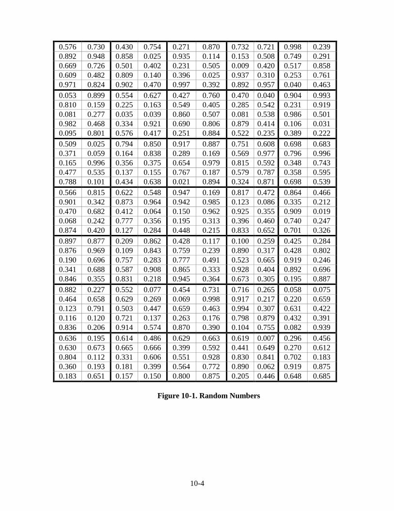
10-4
Figure 10-1. Random Numbers
0.576 0.730 0.430 0.754 0.271 0.870 0.732 0.721 0.998 0.239 0.892 0.948 0.858 0.025 0.935 0.114 0.153 0.508 0.749 0.291 0.669 0.726 0.501 0.402 0.231 0.505 0.009 0.420 0.517 0.858 0.609 0.482 0.809 0.140 0.396 0.025 0.937 0.310 0.253 0.761 0.971 0.824 0.902 0.470 0.997 0.392 0.892 0.957 0.040 0.463 0.053 0.899 0.554 0.627 0.427 0.760 0.470 0.040 0.904 0.993 0.810 0.159 0.225 0.163 0.549 0.405 0.285 0.542 0.231 0.919 0.081 0.277 0.035 0.039 0.860 0.507 0.081 0.538 0.986 0.501 0.982 0.468 0.334 0.921 0.690 0.806 0.879 0.414 0.106 0.031 0.095 0.801 0.576 0.417 0.251 0.884 0.522 0.235 0.389 0.222 0.509 0.025 0.794 0.850 0.917 0.887 0.751 0.608 0.698 0.683 0.371 0.059 0.164 0.838 0.289 0.169 0.569 0.977 0.796 0.996 0.165 0.996 0.356 0.375 0.654 0.979 0.815 0.592 0.348 0.743 0.477 0.535 0.137 0.155 0.767 0.187 0.579 0.787 0.358 0.595 0.788 0.101 0.434 0.638 0.021 0.894 0.324 0.871 0.698 0.539 0.566 0.815 0.622 0.548 0.947 0.169 0.817 0.472 0.864 0.466 0.901 0.342 0.873 0.964 0.942 0.985 0.123 0.086 0.335 0.212 0.470 0.682 0.412 0.064 0.150 0.962 0.925 0.355 0.909 0.019 0.068 0.242 0.777 0.356 0.195 0.313 0.396 0.460 0.740 0.247 0.874 0.420 0.127 0.284 0.448 0.215 0.833 0.652 0.701 0.326 0.897 0.877 0.209 0.862 0.428 0.117 0.100 0.259 0.425 0.284 0.876 0.969 0.109 0.843 0.759 0.239 0.890 0.317 0.428 0.802 0.190 0.696 0.757 0.283 0.777 0.491 0.523 0.665 0.919 0.246 0.341 0.688 0.587 0.908 0.865 0.333 0.928 0.404 0.892 0.696 0.846 0.355 0.831 0.218 0.945 0.364 0.673 0.305 0.195 0.887 0.882 0.227 0.552 0.077 0.454 0.731 0.716 0.265 0.058 0.075 0.464 0.658 0.629 0.269 0.069 0.998 0.917 0.217 0.220 0.659 0.123 0.791 0.503 0.447 0.659 0.463 0.994 0.307 0.631 0.422 0.116 0.120 0.721 0.137 0.263 0.176 0.798 0.879 0.432 0.391 0.836 0.206 0.914 0.574 0.870 0.390 0.104 0.755 0.082 0.939 0.636 0.195 0.614 0.486 0.629 0.663 0.619 0.007 0.296 0.456 0.630 0.673 0.665 0.666 0.399 0.592 0.441 0.649 0.270 0.612 0.804 0.112 0.331 0.606 0.551 0.928 0.830 0.841 0.702 0.183 0.360 0.193 0.181 0.399 0.564 0.772 0.890 0.062 0.919 0.875 0.183 0.651 0.157 0.150 0.800 0.875 0.205 0.446 0.648 0.685

10-5
SAMPLE LOCATION -- PLASTIC CONCRETE
The location where the random sample is obtained is calculated using the random target area procedure of ITM 802 as follows:
1) Select a random number. 2) Multiply the random number by the sublot area to obtain
the Random Target Area.
3) Divide the sample segment size by the width of the area and round to the nearest 0.1 foot length. The resulting number is the length of the random target area.
4) Add this length to the starting station of the sublot to obtain
the testing station.
The following examples explain the procedure for obtaining the random target area:
Example No. 1
A PCCP is being placed at a width of 12 ft and the starting station of the sublot is 102+50. The sublot size is 2400 yd2.
Random Number = 0.830
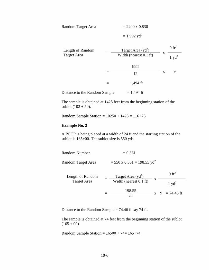
10-6
Random Target Area = 2400 x 0.830
= 1,992 yd2
Length of Random Target Area = Target Area (yd2) x
9 ft2
Width (nearest 0.1 ft) 1 yd2
= 1992
x 9 12
= 1,494 ft
Distance to the Random Sample = 1,494 ft
The sample is obtained at 1425 feet from the beginning station of the sublot (102 + 50).
Random Sample Station = 10250 + 1425 = 116+75
Example No. 2
A PCCP is being placed at a width of 24 ft and the starting station of the sublot is 165+00. The sublot size is 550 yd2.
Random Number = 0.361
Random Target Area = 550 x 0.361 = 198.55 yd2
Length of Random Target Area = Target Area (yd2) x
9 ft2
Width (nearest 0.1 ft) 1 yd2
= 198.55 x 9 = 74.46 ft 24
Distance to the Random Sample = 74.46 ft say 74 ft.
The sample is obtained at 74 feet from the beginning station of the sublot (165 + 00).
Random Sample Station = 16500 + 74= 165+74

10-7
SAMPLE LOCATION -- CORES
The location where the random core for thickness is obtained using the random location per area procedure of ITM 802 is as follows:
1) Identify the sublot from which a random location is required
2) Select a pair or random numbers from the random number
table (Figure 10-1). Use the first number for the longitudinal location and the second number for the transverse location.
3) Determine the length of the sublot 4) Multiply the longitudinal length by the first random number 5) Multiply the transverse width by the second random
number 6) The resulting numbers represent the random location
The station at which a core is taken is determined using the length of pavement required for the sublot of PCCP. The transverse distance is determined using the width of pavement being placed, and is measured from the right edge of the lane determined by looking in the direction of increasing station numbers. Computations for the longitudinal distance and the transverse distance are made to the nearest 1 foot. Cores are not taken at the following locations:
1) Less than 6 in. from the edge of pavement 2) Less than 2 ft from a D-1 contraction joint 3) Less than 3 in. from the longitudinal joint 4) Less than 5 ft from a transverse construction joint
If a core location is less than 6 in. from the edge of pavement, a new location is determined by subtracting or adding 6 in. from the random offset. If a core location is over a dowel bar, a new location is determined by subtracting or adding 3 ft from the random station. If a core location is less than 5 ft from a transverse construction joint, a new location is determined by subtracting or adding 5 ft from the random station.

10-8
Example:
A PCCP is being placed at a width of 12 feet and the starting station of the sublot is 75+00. The sublot size is 2400 yd2.
Length of Sublot =
Sublot Size(yd²) x
9 ft2
Width (nearest 1 ft) 1 yd2
= 2400 x 9 = 1800 ft 12
Random Numbers = 0.935, 0.114 Longitudinal Distance = 1800 x 0.935 = 1683 ft Random Station = (75+00) + (16+83) = 91+83 Transverse Distance = 12 x 0.114 = 1.4 ft (round down to 1 ft)
SAMPLING PROCEDURE
The Contractor is required to provide the concrete and necessary labor for obtaining all required QA samples. QA sampling is performed in accordance with AASHTO T 141.
TRIAL BATCH DEMONSTRATION
A Trial Batch Demonstration, TBD, is required for each proposed concrete mix design submittal, CMDS. TBD requirements are included in Section 501.06. The purpose of the TBD goes beyond verifying that the concrete meets all requirements. The TBD also provides an opportunity for Contractor personnel and the Technician to verify proper equipment calibration and testing procedures prior to any concrete placement on the contract. The Contractor and the PE/PS are required to both be assured that QC testing accurately represents the concrete for any process control decision and QA testing assesses the proper QA adjustment, if any. Failure to accomplish this at the TBD may result in an inaccurate assessment of QA adjustments or erroneous failed material investigations.
The results from a successful TBD provide the Contractor with baseline properties from which to plan process control for production of the concrete mixture. Future changes in properties of aggregates, pozzolans, cements, and admixtures may also be compared to the results at the time of the TBD so effects on concrete properties the day of placement may be anticipated.

10-9
The TBD also provides an opportunity for Contractor personnel and the Technician to witness the process upstream from the plant (i.e. material receipt, storage, and handling), through batching and actual concrete production. The complete process is inspected to provide insight as to any potential process control problems prior to job placement. A properly conducted TBD may work to resolve many problems which would otherwise not become evident until the first day of the pavement construction. The trial batch is required to be of sufficient quantity to allow the Contractor and the Technician to conduct all the required tests from the same batch. The concrete is not to be used for more than one test, except the concrete used for the unit weight may be used to conduct the air content test. The target unit weight and water/cementitious ratio of the concrete are determined by the trial batch. The flexural strength is determined by averaging a minimum of two beam breaks. All Technician test results are given to the Contractor. The TBD test results are required to be added to the submittal of the concrete mix design production, CMDP. An approved CMPD from a previous contract may be considered for approval instead of conducting the trial batch.
QA TESTING
The Technician is responsible for performance of QA testing. For additional information regarding test procedures, refer to Chapter 3 of this manual. QA test results are shared with the Contractor. The flexural strength, air content, unit weight, water/cementitious ratio, and thickness are measured for acceptance. The frequency, test method, and precision of test results are included in Reference 15 of the Manual for Frequency of Sampling and Testing.
FLEXURAL STRENGTH
Flexural strength requirements are included in Section 501.27(c). Average lot values of 570 psi (4,000 kPa) and above shall be achieved. Price adjustments for values outside the tolerance limits will be in accordance with 501.28 Flexural strength testing requires the casting of beams using concrete associated with the paving operation. These beams are allowed to cure and then are placed in a beam breaker that measures the flexural strength of the beam at the time of rupture.

10-10
There are also flexural strength requirements associated with opening newly constructed pavement to construction and non-construction traffic. In addition to the beams cast for acceptance, the Technician needs to also cast sufficient beams to allow for monitoring of the flexural strength required to allow traffic on the newly constructed pavement.
AIR CONTENT
Air content requirements are included in Section 501.27(d). The average lot air content values shall not vary more than -0.8% to +2.4% from the 6.5% target air content. The range of sublot air content values shall not exceed 2.5%. When interpreting air content test results, the Technician must also consider the range of the results across the lot. It is not only important that the concrete air content for the sublot is within the specification tolerances, it is also important that it is consistent throughout the entire pavement.
UNIT WEIGHT
The concrete unit weight requirements are contained in Section 501.27(a). Sublots shall not vary by more than ±3.0% from the target unit weight. A stop paving order will be issued if the plastic unit weight exceeds ±3.0% from the target plastic unit weight (mass). Paving operations shall not resume until satisfactory changes are made or an alternate CMDP is used. The Technician must compare the test result to the concrete mix design production, CMDP, target unit weight. If the test result varies by more than the tolerance included in Section 501.27(a) compared to the target value, the Technician must notify the PE/PS as soon as possible so the paving operation can be suspended. INDOT has determined that the performance of a concrete pavement with a unit weight outside the specification tolerance is of no value. Therefore, the paving operation needs to be suspended immediately upon a failing test result.
WATER/CEMENTITIOUS RATIO
Water/Cementititious, W/C, ratio requirements are included in Section 501.27(b). The weekly water to total cementitious materials ratio shall not vary more than ±0.030 of the target value or exceed 0.450. A stop paving order will be issued if the test results exceed these values. Paving operations shall not resume until satisfactory changes are made or an alternate CMDP is used. The Technician must compare W/C ratio test results to the CMPD target values and the maximum ratio indicated in 501.27(b). Again, the Technician must notify the PE/PS of failing test results as soon as possible so the paving operation can be suspended. W/C ratio is another parameter

10-11
that INDOT has determined results in severe performance problems when the tolerance values are exceeded.
THICKNESS
Thickness requirements are contained in Section 501.26. As discussed earlier, the Technician must be aware of the requirements of ITMs 404 and 802 as well. The location adjustments included in ITM 802 are also important as cores taken near pavement edges or longitudinal joints may not be an accurate representation of the pavement thickness throughout the lot and coring too close to a contraction joint or transverse construction joint could damage a dowel bar or the coring equipment. The Technician needs to follow the ITM 404 requirements for core measurement because the thinkness QA adjustment is based on the measurement and subbase aggregate can attach itself to the bottom of the core which complicates the measurement. The Technician must observe the coring operation and take immediate possession of the cores. This ensures that the cores subjected to the thickness measurement are the ones taken from the pavement at the required location.
SMOOTHNESS
The PCCP smoothness is required to be determined in accordance with Section 501.25. When a profilograph is used to verify smoothness, the Technician is responsible for observing the operation and must take possession of the resulting profilogram immediately upon completion of the profilograph run.
PAY FACTORS
The Technician will be responsible for determination of pay factors associated with test results for flexural strength, air content, air content range, thickness, and smoothness. These pay factors are applied to the product of the quantity and the unit price for the QC/QA PCCP pay item in order to determine the QA adjustment for each lot. The lot QA adjustments for each QC/QA PCCP pay item are then added together to determine the QA adjustment for the contract.
FLEXURAL STRENGTH
The information regarding pay factor determination is found in Section 501.28(a). Concrete that is found to have higher modulus of rupture values make strong pavements that are more likely to provide an acceptable service life.

10-12
AIR CONTENT
Air content pay factor information is included in Section 501.28(b). There are separate pay factors assigned for the lot average air content and for the range of sublot air contents throughout the lot. Air content is different than some other properties as there is a range of acceptable values and as the content varies in either direction, the pavement performance decreases. Concrete with too much air is prone to damage related to moisture and de-icing chemicals and concrete with too little air are susceptible to distresses related to freeze-thaw cycles. This is why there is pay factors associated with the sublot air content range within a lot. The air content tests for a lot might indicate that one sublot has a low content, one has an acceptable content, and one has a high content. The average content for such a situation might justify a pay factor of 1.00 for the lot average, but the reality is that only one sublot has an acceptable air content.
THICKNESS
Thickness pay factor information is contained in Section 501.28(c). Thicker pavements are capable of carrying heavier loads than thinner ones.
SMOOTHNESS
Smoothness pay factors are determined in accordance with Section 501.28(d). Smooth pavements provide a more comfortable ride for the motorist and also provide a longer service life. A rough pavement will be subjected to more impact loading as traffic essentially bounces down the pavement. Smooth pavements cause less bounce from the traffic loads. Impact loading accelerates the pavement deterioration and reduces the service life of the pavement. One item that the Technician must be mindful of when determining the smoothness pay factor is that the maximum value for any smoothness section in which the Contractor takes corrective action is 1.00 regardless of the resulting profile index.
QUALITY ASSURANCE ADJUSTMENT
The QA adjustment for flexural strength, air content, air content range, thickness and smoothness are calculated as follows:
FLEXURAL STRENGTH, AIR CONTENT, AIR CONTENT RANGE
For flexural strength, air content, and air content range determination: q = L x U x (P – 1.00)

10-13
where: q = quality assurance adjustment quantity L = lot quantity U = unit price for QC/QA PCCP pay item, ($/yd2) P = pay factor

10-14
THICKNESS
For sublot thickness determination:
qT = lT x U x (P – 1.00) where: qT = quality assurance adjustment quantity lT = sublot quantity for thickness U = unit price for QC/QA-PCCP, ($/yd2) P = pay factor
SMOOTHNESS
For section smoothness determination: qs = (PFs - 1.00) x A x U
where: qs =quality assurance adjustment for smoothness for one section PFs = pay factor for smoothness A = area of the section, (SYS) U = unit price for the material, ($/SYS)
The quality assurance adjustment for smoothness for the contract, QS, will be the total of the quality assurance adjustments for smoothness, qs, on each section as follows:
Qs = Σ qs
TOTAL QUALITY ASSURANCE ADJUSTMENT
The total quality assurance adjustments are calculated as follows:
QT = Σ (qT1 + qT2 + qT3 ), and
Q = Σ (qF + qA + qR+ QT) + QS
where: Q = total quality assurance adjustment quantity QS = quality assurance adjustment for smoothness qF = lot quality assurance adjustments for flexural strength QT = lot quality assurance adjustments for thickness qA = lot quality assurance adjustments for air content qR = lot quality assurance adjustments for range

10-15
Example:
The PCCP has the following test results. Determine the Quality Assurance Adjustments for the lot. Sublot 1 = 2400 sys Sublot 2 = 2400 sys Sublot 3 = 2400 sys Design Depth (DD) = 14.0 in. Quality Assurance Adjustment for Smoothness (Qs) = - $1200 Unit Price = $32.00/sys
Sublot 1 Sublot 2 Sublot 3 Lot Avg. Pay Factor Flexural Strength 565 psi 560 psi 570 psi 565 psi 0.98 Air Content 6.2% 7.4% 5.3% 6.3% 1.00 Air Content Range 7.4 - 5.3 = 2.1% 1.00 qF = 7200 x 32.00 x (0.98 - 1.00) = - $4608 qA = 7200 x 32.00 x (1.00 - 1.00) = $0 qR = 7200 x 32.00 x (1.00 - 1.00) = $0 Thickness Sublot 1 Sublot 2 Sublot 3 Sublot Average 14.1 in. 13.9 in. 14.4 in. Deviation from DD +0.1 in. -0.1 in. +0.4 in. Pay Factor 1.00 1.00 1.02 Adjustment Quantity 0 0 +1536 QT = 2400 x 32.00 x (1.02 – 1.00) = $1536 QT = 2400 x 32.00 x (1.00 – 1.00) = $0 QT = 2400 x 32.00 x (1.00 – 1.00) = $0 QT = 0 + 0 + 1536 = $1536 Total Quality Assurance Adjustment Q = ∑ (qF + qA + qR + QT) + QS = (-4608 + 0 + 0 + 1536) + (-1200) = - $4,272

10-16
FAILED MATERIALS
Sublot and lot values that are excessively out of tolerance are subject to review by the Failed Materials Committee, FMC, to determine final payment for the affected pavement. The following test results require FMC consideration:
1. An individual sublot having an air content test value of less than 4.5 percent or more than 10.0 percent
2. An individual sublot having a flexural strength test value
less than 500 psi 3. A lot having a flexural strength test value average of 514
psi or less
4. A lot having an air content test value average of less than 4.5% or greater than 10.0%
5. A range of air content of greater than 3.5% 6. A core thickness that is less than the design depth required
pavement thickness by more than 1.00 in.
The FMC may assess a failed materials adjustment that represents a portion or all of the payment that the Contractor received for the work associated with the failed concrete pavement or the FMC may require its removal and replacement.
APPEALS
If the Contractor does not agree with the QA test results for a lot of QC/QA PCCP, an appeal may be submitted. The appeal procedure is outlined in Section 501.29.
PCCP ACCEPTANCE
The requirements associated with PCCP are found in Section 502. Job control testing requirements are included in Section 502.05. Portland cement content ............................................... 564 lbs/cu yd (335 kg/m3) Maximum water/cementitious ratio ...............................................................0.487 Maximum cement reduction for GGBFS replacement ................................... 30% Fly Ash/portland cement substitution ratio......................... 1.25 by weight (mass) 70 Maximum cement reduction for fly ash replacement ..................................... 20% GGBFS/portland cement substitution ratio......................... 1.00 by weight (mass) Slump, formed ................................................................2 to 4 in. (50 to 100 mm) Slump, slipformed .......................................................1.25 to 3 in. (30 to 75 mm) Air..................................................................................................... 5.0% to 8.0% Minimum flexural strength, 3rd point loading, with fly ash ....................................... 550 psi (3,800 kPa) at 28 days

10-17
Relative yield.......................................................................................0.98 to 1.02 In general, PCCP pay items have small quantities. They are typically utilized for mainline pavement for spot improvements such as intersection improvements, site distance corrections, bridge replacements etc. or for approach pavements on any contract. The requirements are similar to those for QC/QA PCCP, but they are different. As is the case for QC/QA PCCP, the Technician is responsible for witnessing sampling and performing acceptance testing of the concrete used in PCCP. The Manual for Frequency of Sampling and Testing includes information regarding the required sampling and testing frequencies associated with PCCP. It is the Technician’s responsibility to ensure that the appropriate number of samples is taken and acceptance tests are performed. PCCP acceptance does not incorporate the lot and sublot concept used by QC/QA PCCP. However, for pavement thickness, PCCP utilizes a system based on subsections as described in Section 502.21(a). Core locations within a thickness subsection are determined randomly in a similar fashion as for QC/QA PCCP. No additional payment will be made for PCCP acceptance test results that exceed Section 502 requirements. All acceptance test results, except for those associated with pavement thickness, that do not comply with Section 502 requirements require that the associated PCCP go through the failed materials process. If a core indicates that pavement thickness within a subsection is deficient, Section 502.21 describes the procedure required to determine the extent of the thin pavement. Section 502.21(c) addresses calculation of the QA adjustment associated with cores that indicate that the deficient thickness is less than or equal to 0.5 in. Sections 502.21(d) and 502.21(e) outline the deficient thickness failed material parameters associated with PCCP that may remain in place with no payment to the Contractor and those associated with removal and replacement of the PCCP. For PCCP, the profilograph is not used to measure smoothness. Smoothness of the pavement is verified using the 10 ft and 16 ft straightedges in accordance with Section 502.20. Also, flexural strength measurements only apply to determining if the pavement can be opened to traffic and not for acceptance.