Certificate Pursuant to section 12 of the Weights and Measures … · 2014. 3. 26. · 1918/74...
19
(1918/74, 1940/69, 2162/92, 2176/78, 2286/55, 2486/56, 2536/57, 2619/40, 2650/56) III(5)a Issue Date: Reference No: 21 January 2014 T1118/0015 Signatory: P R Dixon for Chief Executive National Measurement Office | Stanton Avenue | Teddington | TW11 0JZ | United Kingdom Tel +44 (0)20 8943 7272 | Fax +44 (0)20 8943 7270 | Web www.bis.gov.uk/nmo NMO is an Executive Agency of the Department for Business Innovation & Skills Certificate Pursuant to section 12 of the Weights and Measures Act 1985 Series V009 Revision 1 Certification No. Valid Until Certification No. Valid Until 1918/74 Revision 2 1 March 2016 2486/56 Revision 2 1 March 2016 1940/69 Revision 2 1 March 2016 2536/57 Revision 2 1 March 2016 2162/92 Revision 2 1 March 2016 2619/40 Revision 2 1 March 2016 2176/78 Revision 2 1 March 2016 2650/56 Revision 2 1 March 2016 2286/55 Revision 2 1 March 2016 In accordance with the provisions of section 12 of the Weights and Measures Act 1985, the Secretary of State for Innovation, Universities and Skills hereby certifies as suitable for use for trade a pattern of a liquid flowmeter, as described in the descriptive annex to this Certificate, and having the following characteristics:- DISPENSER: Dispensers described in certification numbers: 1918, 1940, 2162, 2176, 2286, 2486, 2536, 2619 and 2650. SITE CONTROLLER: DOMS PSS 5000 as described in the descriptive annex. KIOSK CONTROL UNIT AND POINT OF SALE: Any compatible approved POS/KCU equipment running PCMS ‘BeanStore’ fuel POS solution as described in the descriptive annex. Under the provisions of section 12(6) of the said Act, the validity of this certificate is limited as shown above. Note: This certificate relates to the suitability of the equipment for use for trade only in respect of its metrological characteristics. It does not constitute or imply any guarantee as to the safety of the equipment in use for trade or otherwise. This revision replaces previous versions of this certificate. Submitted by: The PCMS Group plc Torwood Close Westwood Business Park Coventry, CV4 8HX United Kingdom
Transcript of Certificate Pursuant to section 12 of the Weights and Measures … · 2014. 3. 26. · 1918/74...
(1918/74, 1940/69, 2162/92, 2176/78, 2286/55, 2486/56, 2536/57, 2619/40, 2650/56)
III(5)a
Issue Date: Reference No:
21 January 2014 T1118/0015
Signatory: P R Dixon
for Chief Executive
National Measurement Office | Stanton Avenue | Teddington | TW11 0JZ | United Kingdom Tel +44 (0)20 8943 7272 | Fax +44 (0)20 8943 7270 | Web www.bis.gov.uk/nmo NMO is an Executive Agency of the Department for Business Innovation & Skills
Certificate Pursuant to section 12 of the
Weights and Measures Act 1985 Series V009 Revision 1
Certification No.
Valid Until Certification No.
Valid Until
1918/74 Revision 2 1 March 2016 2486/56 Revision 2 1 March 2016
1940/69 Revision 2 1 March 2016 2536/57 Revision 2 1 March 2016
2162/92 Revision 2 1 March 2016 2619/40 Revision 2 1 March 2016
2176/78 Revision 2 1 March 2016 2650/56 Revision 2 1 March 2016
2286/55 Revision 2 1 March 2016
In accordance with the provisions of section 12 of the Weights and Measures Act 1985, the Secretary of State for Innovation, Universities and Skills hereby certifies as suitable for use for trade a pattern of a liquid flowmeter, as described in the descriptive annex to this Certificate, and having the following characteristics:-
DISPENSER: Dispensers described in certification numbers: 1918, 1940, 2162, 2176, 2286, 2486, 2536, 2619 and 2650.
SITE CONTROLLER:
DOMS PSS 5000 as described in the descriptive annex.
KIOSK CONTROL UNIT AND POINT OF SALE:
Any compatible approved POS/KCU equipment running PCMS ‘BeanStore’ fuel POS solution as described in the descriptive annex.
Under the provisions of section 12(6) of the said Act, the validity of this certificate is limited as shown above.
Note: This certificate relates to the suitability of the equipment for use for trade only in respect of its metrological characteristics. It does not constitute or imply any guarantee as to the safety of the equipment in use for trade or otherwise.
This revision replaces previous versions of this certificate.
Submitted by:
The PCMS Group plc Torwood Close Westwood Business Park Coventry, CV4 8HX United Kingdom

CONTENTS CERTIFICATION NO V009 1 INTRODUCTION 2 CONSTRUCTION 2.1 Hardware 3 OPERATION 3.1 Touch screen appearance 3.2 Pump status 3.3 Pump options 3.4 Additional information 3.5 Operator prompt/input 3.6 Customer display unit (CDU) illustration 3.7 Receipts 3.8 Pictorial representation POS integrated system 4 AUTHORISED ALTERNATIVES ILLUSTRATIONS Figure 1 POS terminal: IBM SUREPOS 300 Figure 2 Barcode reader: Symbol LS9203 Figure 3 EFT card reader: Verifone Model Figure 4 Customer display unit (CDU) Figure 5 Receipt printer Figure 6 Compact cash drawer Figure 7 UPS: APC 350VA Figure 8 DOMS controller PSS5000 Figure 9 Schematic overview POS system interface Figure 10 POS software verification / authenticity Figure 11 Typical BeanStore POS display Figure 12 Pump status buttons Figure 13 Pump options on POS display Figure 14 Additional pop-up windows Figure 15 Examples of typical receipts and print-outs Figure 16 DOMS PSS-5000 Figure 17 Pictorial representation of POS integrated system

Descriptive Annex 1 INTRODUCTION 1.1 General The PCMS Vision BeanStore fuel POS system is a point of sale system comprising one or more approved point of sale (POS) PC terminals connected to a DOMS forecourt site controller which in turn is connected to a number of fuel dispensers. Attached to, or part of, the POS terminal may be a barcode reader, EFT card reader, receipt printer, cash drawer, customer display unit (CDU) and weigh scale. Each POS terminal, a back office PC and the DOMS site controller are connected to the system via a Local Area Network (LAN). 1.2 PCMS ‘BeanStore’ POS Software solution The Vision BeanStore point of sale application is written in the Java software language. It contains a pump controller software module that allows the operator to operate the forecourt devices for the purpose of making a fuel sale (transaction). The pump controller module talks to the forecourt interface software module that in turn contains a transaction processor that is responsible for decoding the transaction data received from the DOMS controller and encapsulating it in an object for use by the POS. The transaction processor contains Java classes (code) that are protected by an MD5 checksum. If any changes are made to this protected code, the checksum changes. The checksum is re-calculated at application startup and compared with the expected checksum value. If the checksum is found to be incorrect the pump controller module is disabled and the POS will not be able to make a fuel sale. In this way the POS is protected from accidental or deliberate changes to the code that is critical to the correct processing of a fuel transaction. The Vision BeanStore application is deployed onto dedicated POS hardware that contains a standard local area network interface that implements the TCP/IP network protocol. This then connects to a DOMS PSS5000 site controller that is responsible for the direct communication with the forecourt devices. The DOMS controller contains a Local Authority Module (LAM) that is responsible for implementing local authority restrictions such as the maximum number of store transactions. The DOMS controller also stores fuel transactions in non-volatile memory until they have been processed by the POS. These transactions are locked on the DOMS controller whilst they are being processed by the POS to prevent them from being accessed by two POS simultaneously. Each PCMS Vision BeanStore Fuel POS system will have its own local database to store transactional data.

Vision BeanStore has been tested in the UK by the National Weights and Measures Laboratory and they have certified that it complies with the WELMEC 7.2 Software Guide and the Measuring Instruments Directive 2004/22/EC for use in a fuel forecourt environment when running on an approved POS hardware platform and when connected to a DOMS PSS5000 site controller. 2 CONSTRUCTION 2.1 Forecourt controller DOMS PSS 5000 The DOMS PSS5000 forecourt controller comprises a metal rectangular box housing the following main components. General views are shown in Figure 16.
• A power supply
• A Central Processing Board (CPU) with 8 serial ports (CPB508):- this has an LCD 16 x 2 character alphanumerical display and a keyboard comprising 5 keys for navigating the menu options, an adjacent legend describes the key functions as also shown in Figure 16.
• Hardware interface modules:- dispensers are connected to the CPU board via an appropriate hardware interface module compatible with the communication protocol of the dispenser.
2.1.1 Software The DOMS PSS5000 has a legal authority module (LAM) for the UK containing specific parameter values and functions. Reference to the PSS 5000 software version number is not normally required, but may be accessed as follows:- typical LAM version number is 498-35-100 and B1EE for the checksum number. These can be viewed by selecting the appropriate menu heading using the operator keys on the CPU. The LAM version number and checksum are accessed as follows:
When the PSS is powered on:
• The first line displays the application software version and the current time.
• The second line displays the W&M Service menu.
• Pressing the Down arrow once, displays the W & M menu which comprises 7 sub-menus, W.1 to W.7.
• Press the right button once to obtain W.1 – LAM INFO and press again to display Version and Checksum information.
2.2 Hardware 2.2.1 POS hardware IBM Surepos 300 33H PC based POS hardware with a processor speed of 2.00 GHZ, 256 Mb or higher RAM and 40 Gb or higher HDD. 15” colour touch-screen operator display. (Figure 1)

2.2.2 Barcode reader The POS can be connected to a barcode reader for scanning product barcodes to recall product and price information. An example of the type of barcode reader would be the Symbol LS9203 barcode reader, connected via USB port. (Figure 2) 2.2.3 EFT card reader The POS can be connected to a chip and pin payment terminal for taking payment by card. An example of the type of card reader would be the Verifone Omni 3750. (Figure 3) 2.2.4 Customer display unit (CDU) The POS can be connected to a customer display unit in order to display information to the customer when they do not have visibility of the main screen. An example of the type of CDU would be the IBM Surepos CDU. This is a free standing unit and displays 2 lines of 20 characters each. This device is connected to the PC via USB. (Figure 4) 2.2.5 Receipt printer The POS can be connected to a receipt printer for printing customer receipts, with or without the VAT information as required. An example of the type of receipt printer is the IBM SureMark (Figure 5) which has the following:
• thermal printing even in harsh retail environments.
• is connected to the PC via USB.
• prints 52 lines per second at 8 lines per inch.
• contains 16 KB data buffer ram. 2.2.6 Cash drawer The POS can be connected to a cash drawer for the secure storage of money. An example of the type of cash drawer is the IBM Compact. (Figure 6) 2.2.7 Uninterruptible power supply (UPS) The POS unit can be protected by an uninterruptible power supply, if required, to protect it if there is a loss of mains power. This will allow the operator to complete any outstanding transactions successfully prior to 15 minute safe shutdown of the system. An example of the type of UPS is the APC 350VA for the POS. (Figure 7)
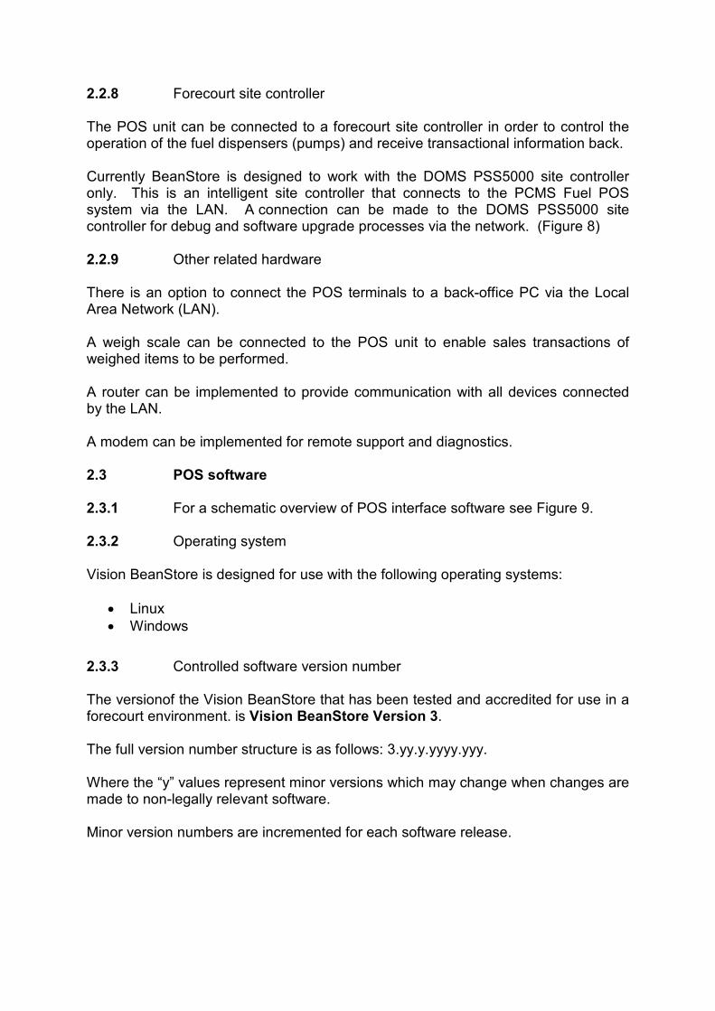
2.2.8 Forecourt site controller The POS unit can be connected to a forecourt site controller in order to control the operation of the fuel dispensers (pumps) and receive transactional information back. Currently BeanStore is designed to work with the DOMS PSS5000 site controller only. This is an intelligent site controller that connects to the PCMS Fuel POS system via the LAN. A connection can be made to the DOMS PSS5000 site controller for debug and software upgrade processes via the network. (Figure 8) 2.2.9 Other related hardware There is an option to connect the POS terminals to a back-office PC via the Local Area Network (LAN). A weigh scale can be connected to the POS unit to enable sales transactions of weighed items to be performed. A router can be implemented to provide communication with all devices connected by the LAN. A modem can be implemented for remote support and diagnostics. 2.3 POS software 2.3.1 For a schematic overview of POS interface software see Figure 9. 2.3.2 Operating system Vision BeanStore is designed for use with the following operating systems:
• Linux
• Windows
2.3.3 Controlled software version number The versionof the Vision BeanStore that has been tested and accredited for use in a forecourt environment. is Vision BeanStore Version 3. The full version number structure is as follows: 3.yy.y.yyyy.yyy. Where the “y” values represent minor versions which may change when changes are made to non-legally relevant software. Minor version numbers are incremented for each software release.

2.3.4 Legally relevant files/software The legally relevant software modules that have been accredited for use in a fuel forecourt and protected by checksum are as follows: Transaction processor 288b30eafbbb15199 2.3.5 To display the version and checksum The Vision BeanStore software version and the fuel specific software module checksum can be displayed by selecting the fuel POS Information option from the Additional Functions tab with the option to print. This brings up a pop-up window with the relevant information. (Figure 10) 2.3.6 Alternative Checksum for Vision Beanstore VBS 3.95.0 build .4731
Application Checksum: 6a355dfbd86ac80e 2.3.7 Alternative Checksum for Vision Beanstore VBS 3.98.0
Application Checksum: 1ecb747754ca0ee87 3 POS OPERATION 3.1 Touch screen appearance The POS terminal has an LCD touch screen, with Icons displayed on the screen to represent buttons. The screen is sensitive to the touch of a finger and initiates a function. Please note that the appearance, colour and layout of the screen are all configurable, and can be tailored to individual client’s requirements and may therefore appear different to the example shown. (Figure 11) 3.2 Pump status During normal operation, or when the POS is in its logon screen, a panel exists at the top of the screen which shows the current status of each pump and allows for the authorisation to dispense fuel and the stopping of pumps. The panel is visible and accessible during all POS functions. This panel contains a number of symbols representing each configured pump. Each pump symbol has an indication of the pump status (colour coded), and acts as a button to control the operation of that pump. Pumps can only be controlled by a POS if the operator has ‘Line Of Sight’ of the pump. In addition a POS can only have a maximum of 8 authorised pumps dispensing fuel at any one time.

All POS will show all pump symbols and their current status. For each pump, irrespective of status, there is an indication of:
• How many fuel transactions dispensed on this pump (stacked) are awaiting payment (maximum of 2)
• Whether or not the stacked fuel transaction has been selected for payment.(Figure 11)
• In addition there is a button that enables the user to disengage ALL pumps to stop their fuel flow, even those not dispensing fuel. To engage, pumps must be restarted independently.
An illustration is available of the possible permutations of pump statuses. (Figure 12) 3.3 Pump options Selecting a pump symbol opens up an additional window below the ‘Pump Status’ window, the contents of which vary depending on the status of the pump. Only those options that are applicable for the status of the selected pump are displayed. (Figure 13) The contents of the 'Pump Option' window can consist of:
The cashier has selected a pump that is calling for authorisation to engage and dispense fuel.
This button appears if the pump is in a dispensing state, and allows the cashier to stop the pump from dispensing fuel.
This button appears if the pump is in a “stopped” or “preset limit reached” state.
Only activated if there is at least one stacked transaction on the pump. NB. Still available if a sale transaction is in progress.
Only activated if there is at least one stacked transaction on the pump & NO sales transaction in progress.
This button appears if the pump is indicating an error.
Indicates the oldest stacked transaction on the pump with the value of the fuel dispensed.
Indicates with a cross that this transaction has been selected for payment.

Displayed if there are 2 stacked transactions on a specific pump. Also illustrated with a cross (as shown above) if the transaction has been selected for payment.
3.4 Additional information The selection of certain buttons in the pump control window can invoke an additional pop-up, containing additional information pertinent to the selected button. Each pop-up box carries a heading which shows which pump option has been selected. Once the nozzle has been replaced after any fuel has been dispensed the transaction is ‘Stacked’ on the pump. The transaction remains on the pump until the cashier selects the transaction and either:
• Tenders the transaction or
• Selects drive off or
• Selects pump test A maximum of 2 transactions can be awaiting payment on any one pump. The pump can be selected and the dispensed transaction can be marked for payment. Once selected it drops down into the cashier transaction window. The fact that the transaction has been selected for payment, is indicated on the pump symbol. More than one dispensed transaction can be added to a single cashier transaction. Should a transaction be recorded on the pump and not be selected for payment within a configurable time limit, then an audible and visual alarm is initiated. The cashier can select the pump and if necessary indicate a ‘drive off’. Alternatively if the customer is still available to make payment, then pressing any pump symbol in the pump status window, stops the indication/alarm. The timer resets for this transaction and the alarm will only re-activate after the configured time. (Figure 14) 3.5 Operator prompt/input Most operator interaction is either by touch screen, for the control of the pumps or by product scanning/selection for shop product. Any function that requires numeric entry (e.g. quantity sale), can be performed with the keypad. Should the entry of non-numeric data be required (e.g. car registration capture) then a full QWERTY keyboard is made available on the touch screen. If an operator is required to select an entry from a list of options (e.g. pay in reason) then a pop-up box is initiated to allow the scrolling and selection of the required entry. 3.6 Customer display unit (CDU) illustration The CDU display illustrates the pump number and transaction which is denoted by an “A” or “B”, when stacked transactions (maximum of 2) are listed on a pump button. (Figure 4)

3.7 Receipts Some sample illustrations of 3 variations of receipts:
• A normal cash sale transaction.
• A cash sale receipt with VAT.
• Software verification / authenticity (NOT a customer receipt). 3.8 Pictorial representation POS integrated system A more detailed pictorial overview of the POS integrated system is represented. (Figure 17) 4 AUTHORISED ALTERNATIVES Currently there is no alternative POS hardware, other than IBM Surepos 300 as recommended. 5 CERTIFICATE HISTORY
ISSUE NO. DATE DESCRIPTION
Certification No 1918/74 Certification No 1940/69 Certification No 2162/92 Certification No 2176/78 Certification No 2286/55 Certification No 2486/56 Certification No 2536/57 Certification No 2619/40 Certification No 2650/56
19th October 2006 19th October 2006 19th October 2006 19th October 2006 19th October 2006 19th October 2006 19th October 2006 19th October 2006 19th October 2006
Type examination certificate first issued. Type examination certificate first issued. Type examination certificate first issued. Type examination certificate first issued. Type examination certificate first issued. Type examination certificate first issued. Type examination certificate first issued. Type examination certificate first issued. Type examination certificate first issued..
Series V009 Revision 1 of above certificates
29th November 2009 - Consolidation of above certificates into one certificate series.
- Section 2.3.6 added – alternative checksum
Series V009 Revision 1 Revision 2 of above certificates
21 January 2014 - Section 2.3.7 added – alternative checksum

Figure 1 POS terminal: IBM SUREPOS 300
Figure 2 Barcode reader: Symbol LS9203
Figure 3 EFT card reader: Verifone model
Figure 4 Customer display unit (CDU) illusrates transaction “A” & “B” on pump 2
Figure 5 Receipt printer Figure 6 Compact cash drawer
Figure 7 UPS: APC 350VA Figure 8 DOMS controller PSS5000

Figure 9 Schematic overview POS system interface

Figure 10 POS software verification / authenticity
Figure 11 Typical Beanstore POS display

Figure 12 Pump status buttons
Figure 13 Pump options on POS display

Figure 14 Additional pop-up windows

Figure 15 Examples of typical receipts and print-outs

(a) DOMS PSS 5000 enclosure (b) DOMS PSS 5000 typical electronic component layout
(c) Central Processing Board (CPB508) display and menu navigation keys
Figure 16 (a, b & c)

© Crown Copyright 2014 National Measurement Office This material may be freely reproduced except for sale.
Figure 17 Pictorial representation of POS integrated system


![Estimation of Decision Alternatives on the Basis of Interval ...fuzzy pairwise comparison matrices (PCMs) [1] and interval PCMs 2]-[8] became widespread. Calculated Calculated [ weights](https://static.fdocuments.us/doc/165x107/60debc89e81239220f18aa47/estimation-of-decision-alternatives-on-the-basis-of-interval-fuzzy-pairwise.jpg)