cern.ch/STEAM€¦ · 1st STEAM Workshop –CERN, Geneva, CH –13 June 2019 3 1. SPICE netlists...
23
1 1 st STEAM Workshop – CERN, Geneva, CH – 13 June 2019 Integrated network modelling 1 st STEAM Workshop 13-14 June 2019 Emmanuele Ravaioli on behalf of the STEAM team With thanks to A. Liakopoulou (UTwente), M. Prioli (INFN) cern.ch/STEAM
Transcript of cern.ch/STEAM€¦ · 1st STEAM Workshop –CERN, Geneva, CH –13 June 2019 3 1. SPICE netlists...

11st STEAM Workshop – CERN, Geneva, CH – 13 June 2019
Integrated network modelling
1st STEAM Workshop 13-14 June 2019
Emmanuele Ravaioli
on behalf of the STEAM team
With thanks to A. Liakopoulou (UTwente), M. Prioli (INFN)
cern.ch/STEAM

21st STEAM Workshop – CERN, Geneva, CH – 13 June 2019
Our integrated approach to network modelling
1. “Simple” circuits: PSPICE schematics → PSPICE netlists and component libraries→ PSPICE / LTSPICE
2. Large circuits: Semi-automatic generation of PSPICE netlists→ SING: STEAM Integrated Network Generator
3. Parametric analyses: Semi-automatic editing and running of PSPICE models→ PSPICE Manager
4. Complex, non-linear, interdependent phenomena: Couple the PSPICE electrical model to other tool(s)
→ COSIM. Examples:• Superconducting magnet model in LEDET or COMSOL• Power supply control model in PSIM
Integrated network modelling
1. PSPICE netlist2. SING3. PSPICE Manager4. COSIM

31st STEAM Workshop – CERN, Geneva, CH – 13 June 2019
1. SPICE netlists (PSPICE/LTSPICE)
We prefer PSPICE netlists over PSPICE schematics because• Netlists are modular and easily expandable• Netlists can be versioned and stored in libraries (on gitlab)• Netlists can be generated programmatically (automation possible)The price to pay: Netlists are more difficult to interpret/debug (comments can be very useful)
Schematic Netlist
Courtesy of M. Maciejewski

41st STEAM Workshop – CERN, Geneva, CH – 13 June 2019
2. Semi-automatic generation of PSPICE netlists (SING)
SING: STEAM Integrated Network Generator https://cern.ch/STEAM/SING
• Automatic generation of netlists• “for-loop” to add many times similar components (examples: turns in a magnet, magnets
in a circuit, etc)• Default simulation options can be set (simulations can be generated by non-expert users)→ Models are generated more quickly and with fewer bugs
LHC main dipole magnet circuit• 154 twin-aperture SC magnets in series• Two power supplies, two energy-extractions,
earthing system, etc• Several thousands components• Used for time-domain analysis
Example 1
Turn-by-turn model of a magnet (MQXF)Each turn is modeled as• Self-inductor• Mutual inductance to all other turns• Capacitance to ground• Used for frequency-domain analysis
Example 2

51st STEAM Workshop – CERN, Geneva, CH – 13 June 2019
LHC main dipole circuit (RB)
Power supply FilterEnergy
Extraction 1
Energy Extraction 2
77 Magnets
Crowbars
77 Magnets
Non-linear electrical model of a superconducting magnet (parasitic capacitances, eddy currents)
[ref1] https://ieeexplore.ieee.org/abstract/document/6126021[ref2] https://ieeexplore.ieee.org/abstract/document/6082398
By-pass Diode
Example 1

61st STEAM Workshop – CERN, Geneva, CH – 13 June 2019
Voltage transients during power-supply switching-off
Magnet 001 BlueMagnet 154 Red
Example 1

71st STEAM Workshop – CERN, Geneva, CH – 13 June 2019
Frequency-domain turn-to-turn model of a magnet pole (MQXFAP1)
Experimental data: J. Taylor (LBNL)
Model validation Effect of a short-circuit
Example 2

81st STEAM Workshop – CERN, Geneva, CH – 13 June 2019
3. Semi-automatic editing and running of PSPICE models
PSPICE Manager
• Edit netlists programmatically• Run simulations programmatically• Dynamically change simulation list based on partial simulation results• Matlab scripts→ Useful for parametric studies, worst-case analyses
LHC main dipole magnet circuit• Simulation of a short-circuit to ground• Parametric studies• Worst-case identification• Simulation parameters in the model to run
changed based on simulation results
Example 3

91st STEAM Workshop – CERN, Geneva, CH – 13 June 2019
Voltages to ground in absence of failures
Voltage To Ground Versus Time Voltage To Ground Versus Magnet Position
Work of A. Liakopoulou
Magnet 001 BlueMagnet 154 Red
Example 3

101st STEAM Workshop – CERN, Geneva, CH – 13 June 2019
Voltages to ground in case of short-circuit to ground at magnet #70
Work of A. Liakopoulou
Voltage To Ground Versus Time Voltage To Ground Versus Magnet Position
Short location
Magnet 001 BlueMagnet 154 Red
Example 3

111st STEAM Workshop – CERN, Geneva, CH – 13 June 2019
Short-circuit simulations – Parametric studies
Work of A. Liakopoulou
Varying Short Resistance Varying 𝒕𝑺𝑯𝑶𝑹𝑻Varying Short Position
• Curve shifts along y axis → Change
of peak voltage to ground values
achieved
• Curve slope changes → Change
of voltage drop over each magnet
• Curve Shifts along y axis →Change of peak voltage to
ground values achieved• Dependent of exponential decay of
current in the circuit
Example 3

121st STEAM Workshop – CERN, Geneva, CH – 13 June 2019
Worst-case analysis – Intermittent short-circuit at magnet #77 -1
Work of A. Liakopoulou
Voltage To Ground Versus Time Voltage To Ground Versus Magnet Position
Current through by-pass diodes of magnets in
positions > short position after t ≈ 1202.07 𝑠
Magnet 001 BlueMagnet 154 Red
Example 3
131st STEAM Workshop – CERN, Geneva, CH – 13 June 2019
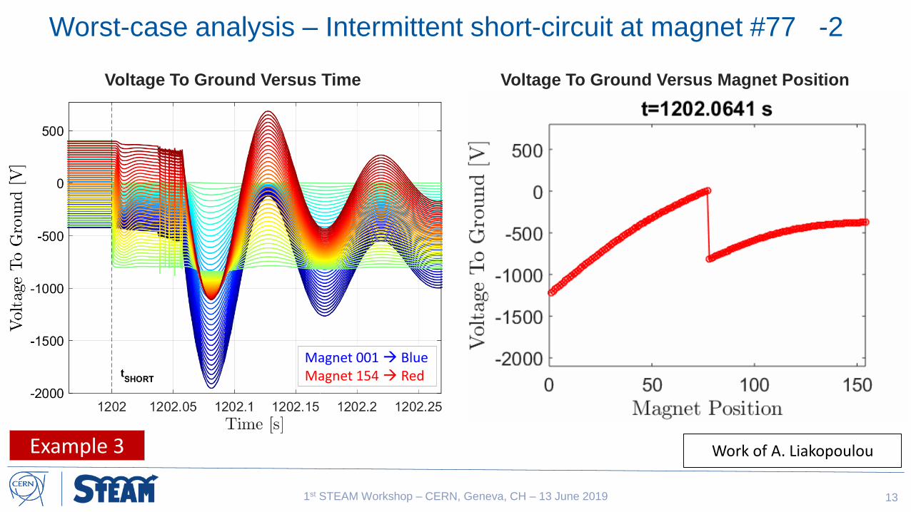
Worst-case analysis – Intermittent short-circuit at magnet #77 -2
Work of A. Liakopoulou
Voltage To Ground Versus Time Voltage To Ground Versus Magnet Position
Magnet 001 BlueMagnet 154 Red
Example 3

141st STEAM Workshop – CERN, Geneva, CH – 13 June 2019
Worst-case analysis – Intermittent short-circuit at magnet #77 -3
Work of A. Liakopoulou
Voltages To Ground Non-Intermittent Short Voltages To Ground Intermittent Short
Peak voltage to ground value is a factor of 2 higher in the case of intermittent
short-circuit, or intermittent blow-up of the fuse in the earthing systemExample 3

151st STEAM Workshop – CERN, Geneva, CH – 13 June 2019
4. Cooperative Simulation
Complex, non-linear, interdependent phenomena
COSIM → A tool to seamlessly couple different software simulating interdependent phenomena occurring in different domains, with different time-scales, different sizes,…
See Michał’s presentation this afternoon !

161st STEAM Workshop – CERN, Geneva, CH – 13 June 2019
New developments?
Send us your wishlist !

171st STEAM Workshop – CERN, Geneva, CH – 13 June 2019
Annex

181st STEAM Workshop – CERN, Geneva, CH – 13 June 2019
Non-linear electrical model of a superconducting magnet
Eddy Currents in the coils
Magnetization Effects
Parasitic Coil-to-Ground Capacitance
Inhomogeneous AC behavior of the two
apertures of the dipole
Different frequency response
Phase-velocity of the wave changing along the
dipole chain
Each aperture shifts the wave of a different angle
L = Laperture = 49 mH
C = Cground = 150 nF
k = 0.75
7 Ω < R1,2 < 10 Ω
2
41
41
/1
1/1
sC
LksC
RkLR
s
LkkR
ssL
sz
a
a
a
a
[ref1] https://ieeexplore.ieee.org/abstract/document/6126021[ref2] https://ieeexplore.ieee.org/abstract/document/6082398

1919
Grounding Subcircuit
Fuse behavior:
Pre-arcing Threshold
Reached
Blow-up Threshold
Reached Fuse stays blown up
Fuse enters state of
intermittent blow up
Challenge in fuse modeling! : Profile of current through fuse
over time needed in order to calculate times thresholds are reached
• Fuse modelled as voltage controlled switch
with blow-up behavior achieved by input
stimulus
• In order to include fuse blow up behavior in the
model knowledge of the following is needed:
- Thermal load of the fuse ( 𝐼𝐹𝑈𝑆𝐸2 𝑑𝑡)
- Time Pre-Arcing threshold is reached
- Time Blow-Up threshold is reached
Figure: Grounding Subcircuit Of LHC Main Dipole Circuit

201st STEAM Workshop – CERN, Geneva, CH – 13 June 2019
Simulation Scheme for Intermittent Short
Work of A. Liakopoulou
PSpice: Solves Netlist Provided by MATLAB (3 simulations in total)
MATLAB: - Main Loop Interface
- Numerical Integration
- Simulation data exchange using STEAM PSpice Manager

2121
Simplified LHC Main Dipole Circuit
Differential Circuit Equations:
Solving analytical equation allows for calculation of voltage to ground during slow
transients in half the time required for numerical simulations
Main Simplifications:
• No capacitors to ground (effect visible during fast transients)
• Constant voltage across a quenched magnet due to the Cold
Diode and constant value of energy extraction resistance
• Simplified models for power supply, energy extraction and
magnets

2222
Identification of Short ResistanceComparison of measured and
analytically calculated voltage to ground
for 𝑹𝑺𝑯𝑶𝑹𝑻 = 𝟏 𝛀
Comparison of measured and
analytically calculated voltage to ground
for 𝑹𝑺𝑯𝑶𝑹𝑻 = 𝟏𝟎 𝛀
Voltage to ground values for all resistance ranges computed in 8 seconds
• Algorithm identifies short resistance value by identifying smallest distance of measured curve
for specific resistance ranges

2323
Identification of Short PositionVoltage To Ground Versus Time
• Smallest Distance Identified for
magnets in positions
• Magnet where short occurred identified
as having the 4th smallest distance
• Voltage to ground values for
all 154 magnet positions
computed in 77 seconds