
PARTICLE DETECTORS Günther Dissertori CERN-EP CERN Teachers Seminar July 2001.
CER
N-A
CC
-NO
TE-2
014-
0093
14/1
1/20
14
CERN-ACC-NOTE-2014-0093
2014-11-17
New Electron Cloud Detectors for the PS Main Magnets
Christina Yin Vallgren, Paolo Chiggiato, Simone Gilardoni, Mauro Taborelli, HolgerNeupert, Jose Ferreira Somoza
Keywords: Proton Synchrotron, Electron cloud, vacuum,Electron-photon-emission, Opera, MolFlow+, pick-up
Summary
Electron cloud (EC) has already been observed during normal operation of the PS,therefore it is necessary to study its influence on any beam instability for the futureLHC Injector Upgrade (LIU). Two new electron cloud detectors have been discussed,developed and installed during the Long Shutdown (LS1) in one of the PS main magnets.The first measurement method is based on current measurement by using a shieldedbutton-type pick-up. Due to the geometry and space limitation in the PS magnet, thebutton-type pick-up made of a 96%Al2O3 block coated with a thin layer of solvent-basedAg painting, placed 30 degrees to the bottom part of the vacuum chamber was installedin the horizontal direction where the only opening of the magnet coil is. The other newlydeveloped measurement method is based on detection of photons emitted by the electronsfrom the electron cloud impinging on the vacuum chamber walls. The emitted photonsare reflected to a quartz window. A MCP-PMT (Micro-Channel Plate PhotomultiplierTube) with high magnetic field/radiation resistance and fast response is attached outsidethe quartz window behind two UV lenses and one UV mirror and then counts the photonsduring the beam operation.
1 Introduction
Electron cloud (EC) has been observed during normal operation of the PS, but withoutcausing any degradation of the beam quality. It only appears during the last stages ofthe cycle of the production of the LHC type beams. The duration of the EC interactionwith the beam is not long enough to trigger any instability, more details can be found in[1] . However, it is not yet clear whether the beams for the LIU (LHC Injectors upgrade)-project will be affected by EC. A series of machine development runs and simulationstudies have been carried out to identify the electron cloud effects in the PS during the
1
last few years [2, 3, 4]. This note starts with a short introduction of the existing electroncloud measurement set-ups installed in the straight sections of the PS and then focuses onnew developments of the set-ups installed in a PS main magnet during the Long Shutdown1 (LS1).
2 The existing electron cloud set-ups in the PS straightsections
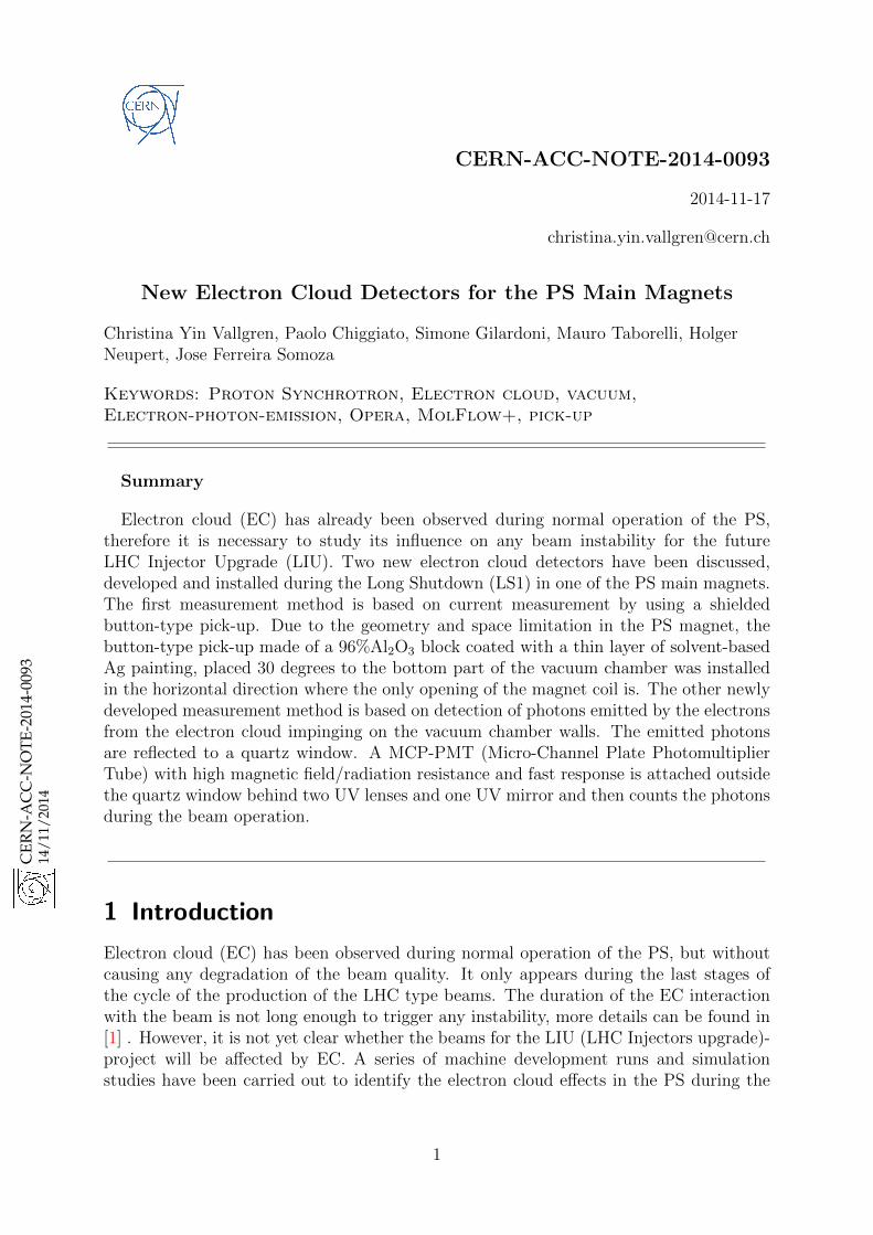
The first electron cloud set-up in the PS was installed in Straight Section (SS) 98 in2007. It consists of an elliptical vacuum chamber of bare stainless steel with dimensions1050×146×70mm. It is equipped with two button pick-ups on the top of the vacuumchamber; one penning gauge installed close to the pick-ups and one special antechamberfor a clearing electrode (stripline electrode) without aperture reduction (Fig. 1). A smalldipole was also installed to apply a magnetic field at a range from 0.5 to 20 mT, which isby far lower than the dipole field in a PS main magnet (1.2 T). A second identical set-upwas installed in PS SS84 in 2008 with a vacuum chamber coated with amorphous carbon.The details of the set-up, as well as the previous measurement results, can be found in[2, 3, 4].
length of 1050 mm. Two identical 30 mm diameter buttonpickups and a Penning gauge are installed on the upper partof the vacuum chamber. The pickups are both shieldedfrom the main chamber with 0.7 mm thick perforatedstainless steel sheets, which provide a transparency of10% for pickup #1. As a different approach, pickup #2 isshielded with two higher transparency (37%, 23%) grids.The Penning gauge is shielded with a 37% transparencygrid and installed behind a 90� elbow in order to protect itagainst electrons. All shielding grids are electricallygrounded to the vacuum chamber. On the bottom side ofthe vacuum chamber, a 400 mm long, 46 mm wide, and2 mm thick 316 LN stainless steel clearing electrode isinstalled inside a small antechamber in order to avoid anyaperture reduction for the beam. The installation is de-picted schematically in Fig. 1.
The stripline-type electrode is mounted on and sup-ported by two standard high-voltage feedthroughs. Theelectrode geometry was optimized for its function as partof an electron cloud diagnostics equipment. The gapbetween the electrode and the adjacent beam pipe wasmade small in order not to lose too many electrons in thegap, which would reduce the EC by geometrical means.The line impedance to ground of the electrode is about
30 �, which means that the mismatch to the connected50 � coaxial cable is acceptable. As for every new instal-lation, the beam coupling impedance of the chamber had tobe checked. Since the vacuum diagnostics port and thebutton pickups are behind shielding grids, only the striplineelectrode has a significant impact on the impedance. Bynumerical simulations, using CST MICROWAVE STUDIO�,the longitudinal and transverse impedance were found tobe of the order of 0.1% of the present PS impedance andthus negligible.Since the experiment is mounted in a field-free region in
the PS, the central part of the electron cloud detector issurrounded by a small C-shaped dipole magnet that canproduce a homogenous magnetic field of up to 100 G [23].A picture of the experimental area in the PS is shown inFig. 2.The signals from the button pickups and from the
stripline electrode were transmitted to a local controlroom using about 44 m long 50 � coaxial low-loss cables.In addition to being a clearing electrode, the stripline wasused as a pickup to get a wideband beam signal. A custom-built frequency separating filter was used to observe thebeam signals with the possibility of applying a bias voltageup to �1 kV on the electrode.A similar bias network was implemented for the button
pickups with a maximum bias voltage of �500 V. Low-noise preamplifiers were used for observing the signal on asampling scope. The 3 dB bandwidth of the entire signaltransmission and treatment chain was about 0.045 to350 MHz, which yields a rise time of about 0.94 ns.
III. RESULTS
First, the rf gymnastics in the PS should be outlined,since these determine the bunch length, which is a crucialfactor for the EC buildup. A more detailed description ofthe rf manipulations can be found in [24]. For the produc-tion of the nominal LHC beam, six bunches are injected
BPU 1 BPU 2Vacuumgauge
Stripline upstream Stripline downstream
BeamB
BPU
Stripline
FIG. 1. (Color) Schematic view of the PS electron cloud experi-ment, comprising a shielded Penning gauge, two shielded buttonpickups (BPU), a stripline clearing electrode, and a dipolemagnet (not sketched). Left: Longitudinal cut, right: transversecut at the position of a BPU.
FIG. 2. (Color) Left: Picture of the new electron cloud experiment installed in PS straight section 98, containing two shielded buttonpickups, a shielded Penning gauge, a clearing electrode, and a small dipole magnet. Right: Downstream view into the vacuum chambershowing the stripline electrode at the bottom.
MAHNER, KROYER, AND CASPERS Phys. Rev. ST Accel. Beams 11, 094401 (2008)
094401-2
Figure 1: The set-up of the existing electron cloud experiment installed in PS SS98, con-taining two shielded button pick-ups, a shielded penning gauge, a clearing elec-trode and a small dipole magnet [2].
Within the LHC Injectors Upgrade (LIU) project it is necessary to assess whether theEC instability or incoherent effect could degrade the beam quality on the timescale of thenominal cycle for the high intensity and high brightness beams foreseen for the LHC Injec-tor Upgrade (LIU). Therefore several studies were carried out in order to develop a reliableelectron cloud model of the PS vacuum chambers, identify possible future limitations andfind suitable countermeasures. The recent measurement results and the benchmarkingwith the simulation were summarized in [3, 4].
2
3 The new measurement set-up development forelectron cloud studies in the PS magnet
Electron cloud build-up has successfully been measured and validated in the straightsections of the PS [2], however, no direct diagnostics has been implemented inside anymain magnet in the PS to gain a full understanding of the observed phenomena. Accordingto the electron cloud simulations [1], an induced dipole in a straight section (as shownin Fig. 1) does not represent the real situation in a combined function magnet due tothe different geometries of the chambers and the difference in the magnetic fields. Sincemore than 90% of the PS ring consists of PS main magnets, it is necessary to observeelectron cloud inside a combined function magnet of the PS, in order to provide predictionof the EC build-up distribution in the PS magnets for higher intensity beams as well asvalidation of the EC simulation models and codes.
Most experiments either use retarding field analyzers, button-type pick-ups (as theexisting electron cloud measurement set-up) and stripline electrodes to detect the electronsand beam induced signals locally, or use RF phase shift versus total beam intensity todetermine the integrated electron cloud density over a long section. Considering thegeometry and space limitation of the PS magnet vacuum chamber, two measurementdevelopments have been brought up to discussion, carefully studied and presented indetail here. The preliminary results obtained from the first measurements done with theLHC type beams are also presented here.
3.1 Development 1: Shielded button-type pick-up in the PS magnet
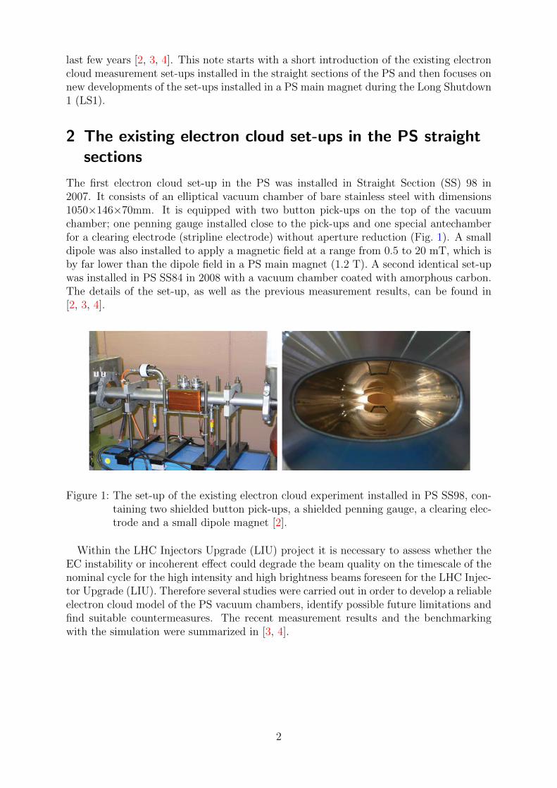
By using the same principle as the existing electron cloud monitor in the PS straightsection, a dedicated shielded pick-up has been designed and installed. The ideal location todirectly measure the electron cloud density inside a magnet vacuum chamber is obviouslyon the top/bottom of the vacuum chamber, in the axis perpendicular to the magnetic field.However, due to space limitation, the button-type pick-up together with its DN35 flange isplaced 30 degrees to the bottom part of the vacuum chamber. It has been inserted in thehorizontal direction where the only opening of the magnet coil is, as illustrated in Fig. 2.The pick-up consists of a ceramic block made of 96%Al2O3 coated with a thin layer ofsolvent-based Ag painting to create electrical conductivity and it is shielded from the mainchamber with a 0.2 mm thick stainless steel sheet with a series of holes (1 mm diameterand 2 mm pitch) providing a geometrical transparency of 5%. The stainless steel shield iselectrically grounded to the magnet vacuum chamber with three RF fingers. The distancebetween the tip of the pick-up and the bottom of the vacuum chamber wall is 12 mm.During the EC measurements, the displacement of the LHC beams can be arranged bythe radial steering up to a maximum of 30 mm from the center of the chamber towardsthe pick-up to maximize the electron cloud signal. The first design version is provided inFig. 2. Since the button-type pick-up is installed behind the shielding grid, it should notaffect the beam coupling impedance of the chamber. As seen in Fig. 2, there are two metalbars between the magnet coil; the gap between the two metal bars is only 90 mm, whichleads to a slight practical difficulty to insert and mount the pick-up together with theDN35 flange into the magnet vacuum chamber. Therefore, a flexible stainless steel armconnecting the DN35 flange and the pick-up is introduced to make the insertion easier.The stainless steel arm can be bent upwards and the distance between the flange and the
3
pick-up can be adjusted within an interval of 10 mm.
BNC coaxial connector
DN40 CF Flange with feedtrough from LESKER
St. Steel arm welded on flange
Al2O3 ceramic part Silver painted on blue surfaces
St. Steel sheet th 0.2mm welded on the support
Holes Ø1mm / space 2mm
Contacts with vacuum chamber
St. Steel parts
ELECTRON PICK-UP FOR MU98 VACUUM CHAMBER
Figure 2: Final design of the MU98 vacuum chamber equipped with the shielded button-type pick-up (CDD number: PS VIECA0001).
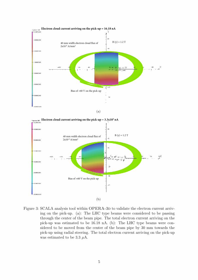
The efficiency of the current measurement arriving on the pick-up was validated usingSCALA tool within OPERA-3d, which is a program widely used for analysis of chargedparticles in electromagnetic fields. The geometry of the vacuum chamber with the pick-up has been slightly simplified to save computing time. Two cases were considered andsimulated using OPERA-3d, one with the beam passing through the center of the beampipe and the other with the beam moved horizontally 30 mm from the center of the beampipe toward the pick-up. In both cases, an electron cloud flux of 40 mm width and 2×10⁻⁶
A/mm2 according to the simulation results provided in [1] was assumed. A magnetic fieldof 1.2 T was applied perpendicular to the beam pipe and the bias on the pick-up wasassumed to be +60 V. In the case of the central LHC type beams, the total electroncurrent arriving on the pick-up was estimated to be 16.18 nA whereas in the case of the30 mm off-set beams, the total electron current could reach 3.3 µA, as shown in Fig. 3.
3.2 Development 2: Electron cloud measurement viaelectron-photon emission
3.2.1 Theory
Instead of directly measuring the electron current in the vacuum chamber, a new methodto measure electron cloud density via electron-photon emission has been applied. This is
4
B (y) = 1.2 T40 mm width electron cloud flux of2x10-6 A/mm2
Bias of +60 V on the pick-up
Electron cloud current arriving on the pick-up = 16.18 nA
(a)
B (y) = 1.2 T40 mm width electron cloud flux of2x10-6 A/mm2
Electron cloud current arriving on the pick-up = 3.3x10³ nA
Bias of +60 V on the pick-up
(b)
Figure 3: SCALA analysis tool within OPERA-3d to validate the electron current arriv-ing on the pick-up. (a): The LHC type beams were considered to be passingthrough the center of the beam pipe. The total electron current arriving on thepick-up was estimated to be 16.18 nA. (b): The LHC type beams were con-sidered to be moved from the center of the beam pipe by 30 mm towards thepick-up using radial steering. The total electron current arriving on the pick-upwas estimated to be 3.3 µA.
5
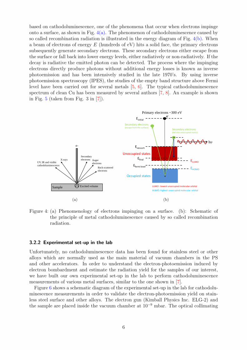
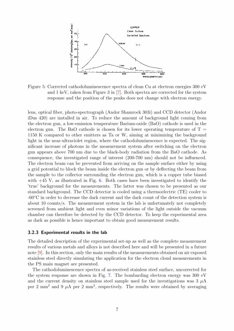
based on cathodoluminescence, one of the phenomena that occur when electrons impingeonto a surface, as shown in Fig. 4(a). The phenomenon of cathodoluminescence caused byso called recombination radiation is illustrated in the energy diagram of Fig. 4(b). Whena beam of electrons of energy E (hundreds of eV) hits a solid face, the primary electronssubsequently generate secondary electrons. These secondary electrons either escape fromthe surface or fall back into lower energy levels, either radiatively or non-radiatively. If thedecay is radiative the emitted photon can be detected. The process where the impingingelectrons directly produce photons without additional energy losses is known as inversephotoemission and has been intensively studied in the late 1970’s. By using inversephotoemission spectroscopy (IPES), the studies of the empty band structure above Fermilevel have been carried out for several metals [5, 6]. The typical cathodoluminescencespectrum of clean Cu has been measured by several authors [7, 8]. An example is shownin Fig. 5 (taken from Fig. 3 in [7]).
e-
Sample
Excited volume
X-rays UV, IR and visible
cathodoluminescence
Secondary
electrons Auger
electrons
Back-scattered
electrons
(a)
Einitial
Evacuum
Efinal
Efermi level
e-
ELUMO
EHOMO
LUMO : lowest unoccupied molecular orbital
HUMO: highest unoccupied molecular orbital
Secondary electrons (escape from the surface)
Secondary electrons (fall into unoccupied states)
h𝜐
Primary electrons ~300 eV
Unoccupied states
Occupied states
(b)
Figure 4: (a) Phenomenology of electrons impinging on a surface. (b): Schematic ofthe principle of metal cathodoluminescence caused by so called recombinationradiation.
3.2.2 Experimental set-up in the lab
Unfortunately, no cathodoluminescence data has been found for stainless steel or otheralloys which are normally used as the main material of vacuum chambers in the PSand other accelerators. In order to understand the electron-photoemission induced byelectron bombardment and estimate the radiation yield for the samples of our interest,we have built our own experimental set-up in the lab to perform cathodoluminescencemeasurements of various metal surfaces, similar to the one shown in [7].
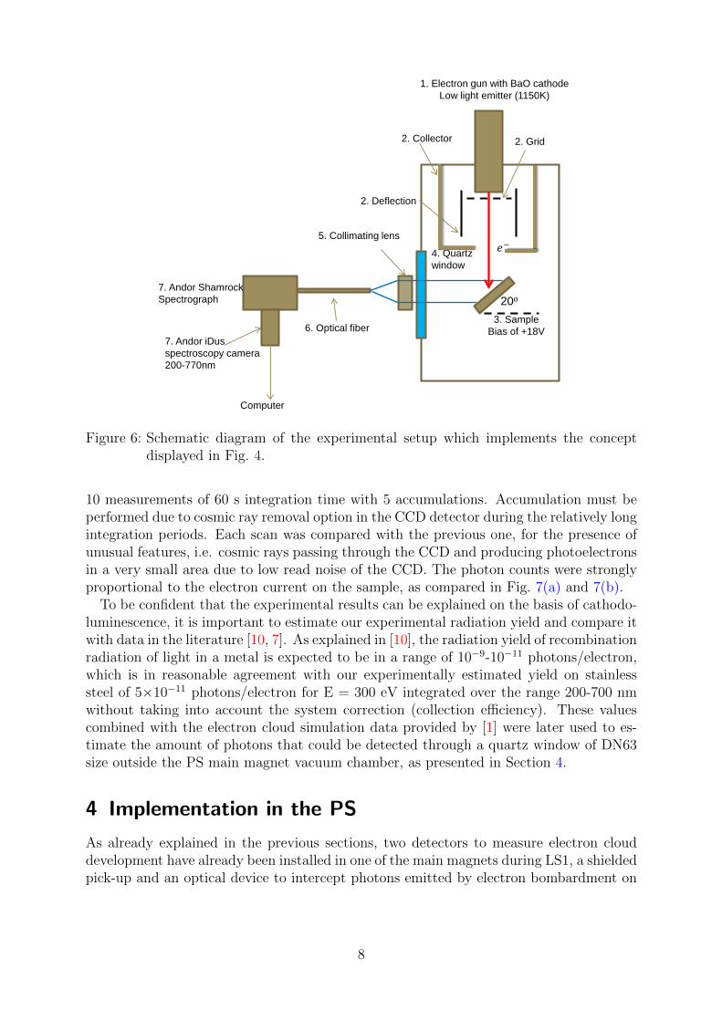
Figure 6 shows a schematic diagram of the experimental set-up in the lab for cathodolu-minescence measurements in order to validate the electron-photoemission yield on stain-less steel surface and other alloys. The electron gun (Kimball Physics Inc. ELG-2) andthe sample are placed inside the vacuum chamber at 10−9 mbar. The optical collimating
6
Cathodoluminescence of copper and nickel surfaces 405
i-
!-
I I I I I 6 5 4 3
ENERGY (eV) 2
COPPER
Clean Surface
300 eV
Uncorrected Spectrum
L
Fig. 2. Cathodoluminescence spectrum of clean Cu. The spectrum is uncorrected for the system response.
COPPER
Clean Surface
Corrected Spectrum
I, 1 ,,I,,,,,,,,,,,,,,, 200 300 400 500 600
WAVELENGTH (nm)
Fig. 3. Corrected cathodoluminescence spectra of clean Cu at electron energies 300 eV and 1 keV.
The 230 nm peak appears in every uncorrected lumines- cence spectrum of copper and nickel and it is independent of the surface condition. This peak does not appear in the corrected spectra. It is due to an apparent drop in the transmittance of quartz at 240nm. Filters, lenses, P-M tube window and P-M chamber window are all made of quartz.
A comparison of the luminescence spectra for both Cu and Ni before and after oxidation (Figs. 3,6-S) shows that the 520nm peak can be associated unequivocally to the existence of an oxide layer. The peak disappeared after proper cleaning of the surface. This result substantiates our contention that thin films of insulators and semicon- ductors can luminesce much more efficiently than metals,
so for any reliable measurement of luminescence from metal the surface must be clean.
This 520nm green luminescence, which appears on oxidized surfaces of Cu and Ni, is also observed on oxidized surfaces of Ta and stainless steel. It is not observed, however, on cleaved surfaces of MO&, a layer compound with extremely inert surface property. The emitted light therefore is most likely characteristic of 02- ions rather than of the various compounds.
The green luminescence is visible in a dark room. The light is not emitted uniformly from the surface, rather, it takes the form of a uniformly distributed high density of fine points covering the whole surface, with the emission at a few scratches, introduced during mechanical polishing,
Figure 5: Corrected cathodoluminescence spectra of clean Cu at electron energies 300 eVand 1 keV, taken from Figure 3 in [7]. Both spectra are corrected for the systemresponse and the position of the peaks does not change with electron energy.
lens, optical fiber, photo-spectrograph (Andor Shamrock 303i) and CCD detector (AndoriDus 420) are installed in air. To reduce the amount of background light coming fromthe electron gun, a low-emission temperature Barium-oxide (BaO) cathode is used in theelectron gun. The BaO cathode is chosen for its lower operating temperature of T =1150 K compared to other emitters as Ta or W, aiming at minimizing the backgroundlight in the near-ultraviolet region, where the cathodoluminescence is expected. The sig-nificant increase of photons in the measurement system after switching on the electrongun appears above 700 nm due to the black-body radiation from the BaO cathode. Asconsequence, the investigated range of interest (200-700 nm) should not be influenced.The electron beam can be prevented from arriving on the sample surface either by usinga grid potential to block the beam inside the electron gun or by deflecting the beam fromthe sample to the collector surrounding the electron gun, which is a copper tube biasedwith +45 V, as illustrated in Fig. 6. Both cases have been investigated to identify the’true’ background for the measurements. The latter was chosen to be presented as ourstandard background. The CCD detector is cooled using a thermoelectric (TE) cooler to-60◦C in order to decrease the dark current and the dark count of the detection system isabout 10 counts/s. The measurement system in the lab is unfortunately not completelyscreened from ambient light and even minor variations of the light outside the vacuumchamber can therefore be detected by the CCD detector. To keep the experimental areaas dark as possible is hence important to obtain good measurement results.
3.2.3 Experimental results in the lab
The detailed description of the experimental set-up as well as the complete measurementresults of various metals and alloys is not described here and will be presented in a futurenote [9]. In this section, only the main results of the measurements obtained on air exposedstainless steel directly simulating the application for the electron cloud measurements inthe PS main magnet are presented.
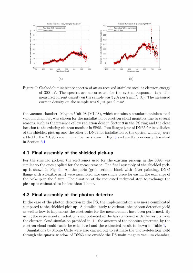
The cathodoluminescence spectra of as-received stainless steel surface, uncorrected forthe system response are shown in Fig. 7. The bombarding electron energy was 300 eVand the current density on stainless steel sample used for the investigations was 3 µAper 2 mm2 and 9 µA per 2 mm2, respectively. The results were obtained by averaging
7
1. Electron gun with BaO cathode Low light emitter (1150K)
3. Sample Bias of +18V
4. Quartz window
5. Collimating lens
6. Optical fiber
7. Andor Shamrock Spectrograph
Computer
7. Andor iDus spectroscopy camera 200-770nm
𝑒𝑒−
20o
2. Grid
2. Deflection
2. Collector
Figure 6: Schematic diagram of the experimental setup which implements the conceptdisplayed in Fig. 4.
10 measurements of 60 s integration time with 5 accumulations. Accumulation must beperformed due to cosmic ray removal option in the CCD detector during the relatively longintegration periods. Each scan was compared with the previous one, for the presence ofunusual features, i.e. cosmic rays passing through the CCD and producing photoelectronsin a very small area due to low read noise of the CCD. The photon counts were stronglyproportional to the electron current on the sample, as compared in Fig. 7(a) and 7(b).
To be confident that the experimental results can be explained on the basis of cathodo-luminescence, it is important to estimate our experimental radiation yield and compare itwith data in the literature [10, 7]. As explained in [10], the radiation yield of recombinationradiation of light in a metal is expected to be in a range of 10−9-10−11 photons/electron,which is in reasonable agreement with our experimentally estimated yield on stainlesssteel of 5×10⁻¹¹ photons/electron for E = 300 eV integrated over the range 200-700 nmwithout taking into account the system correction (collection efficiency). These valuescombined with the electron cloud simulation data provided by [1] were later used to es-timate the amount of photons that could be detected through a quartz window of DN63size outside the PS main magnet vacuum chamber, as presented in Section 4.
4 Implementation in the PS
As already explained in the previous sections, two detectors to measure electron clouddevelopment have already been installed in one of the main magnets during LS1, a shieldedpick-up and an optical device to intercept photons emitted by electron bombardment on
8
100 200 300 400 500 600 700 800−100
0
100
200
300
400
500
600
700
800Oxidized stainless steel, I(sample)=3µA/2mm2
Wavelength [nm]
Inte
nsity
[Cou
nts
for
60s
with
5 a
ccum
elat
ions
]
Raw data of 10 measurementsSmooth data
(a)
100 200 300 400 500 600 700 800−100
0
100
200
300
400
500
600
700
800Oxidized stainless steel, I(sample)=9µA/2mm2
Wavelength [nm]
Inte
nsity
[Cou
nts
for
60s
with
5 a
ccum
elat
ions
]
Raw data of 10 measurementsSmooth data
(b)
Figure 7: Cathodoluminescence spectra of an as-received stainless steel at electron energyof 300 eV. The spectra are uncorrected for the system response. (a): Themeasured current density on the sample was 3 µA per 2 mm2. (b): The measuredcurrent density on the sample was 9 µA per 2 mm2.
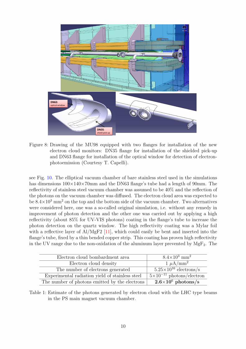
the vacuum chamber. Magnet Unit 98 (MU98), which contains a standard stainless steelvacuum chamber, was chosen for the installation of electron cloud monitors due to severalreasons, such as the presence of low radiation dose in Sector 9 in the PS ring and the closelocation to the existing electron monitor in SS98. Two flanges (one of DN35 for installationof the shielded pick-up and the other of DN63 for installation of the optical window) wereadded to the MU98 vacuum chamber as shown in Fig. 8 and partly previously describedin Section 3.1.
4.1 Final assembly of the shielded pick-up
For the shielded pick-up the electronics used for the existing pick-up in the SS98 wassimilar to the ones applied for the measurement. The final assembly of the shielded pick-up is shown in Fig. 9. All the parts (grid, ceramic block with silver painting, DN35flange with a flexible arm) were assembled into one single piece for easing the exchange ofthe pick-up in the future. The duration of the requested technical stop to exchange thepick-up is estimated to be less than 1 hour.
4.2 Final assembly of the photon detector
In the case of the photon detection in the PS, the implementation was more complicatedcompared to the shielded pick-up. A detailed study to estimate the photon detection yieldas well as how to implement the electronics for the measurement have been performed. Byusing the experimental radiation yield obtained in the lab combined with the results fromthe electron cloud simulation provided in [1], the amount of the photons generated by theelectron cloud could easily be calculated and the estimated result is shown in Table 1.
Simulations by Monte Carlo were also carried out to estimate the photo-detection yieldthrough the quartz window of DN63 size outside the PS main magnet vacuum chamber,
9
DN63: optical window
DN35: shield pick-up
Figure 8: Drawing of the MU98 equipped with two flanges for installation of the newelectron cloud monitors: DN35 flange for installation of the shielded pick-upand DN63 flange for installation of the optical window for detection of electron-photoemission (Courtesy T. Capelli).
see Fig. 10. The elliptical vacuum chamber of bare stainless steel used in the simulationshas dimensions 100×140×70mm and the DN63 flange’s tube had a length of 90mm. Thereflectivity of stainless steel vacuum chamber was assumed to be 40% and the reflection ofthe photons on the vacuum chamber was diffused. The electron cloud area was expected tobe 8.4×103 mm2 on the top and the bottom side of the vacuum chamber. Two alternativeswere considered here, one was a so-called original simulation, i.e. without any remedy inimprovement of photon detection and the other one was carried out by applying a highreflectivity (about 85% for UV-VIS photons) coating in the flange’s tube to increase thephoton detection on the quartz window. The high reflectivity coating was a Mylar foilwith a reflective layer of Al/MgF2 [11], which could easily be bent and inserted into theflange’s tube, fixed by a thin bended copper strip. This coating has proven high reflectivityin the UV range due to the non-oxidation of the aluminum layer prevented by MgF2. The
Electron cloud bombardment area 8.4×103 mm2
Electron cloud density 1 µA/mm2
The number of electrons generated 5.25×10¹⁶ electrons/sExperimental radiation yield of stainless steel 5×10⁻¹¹ photons/electron
The number of photons emitted by the electrons 2.6×10⁶ photons/s
Table 1: Estimate of the photons generated by electron cloud with the LHC type beamsin the PS main magnet vacuum chamber.
10
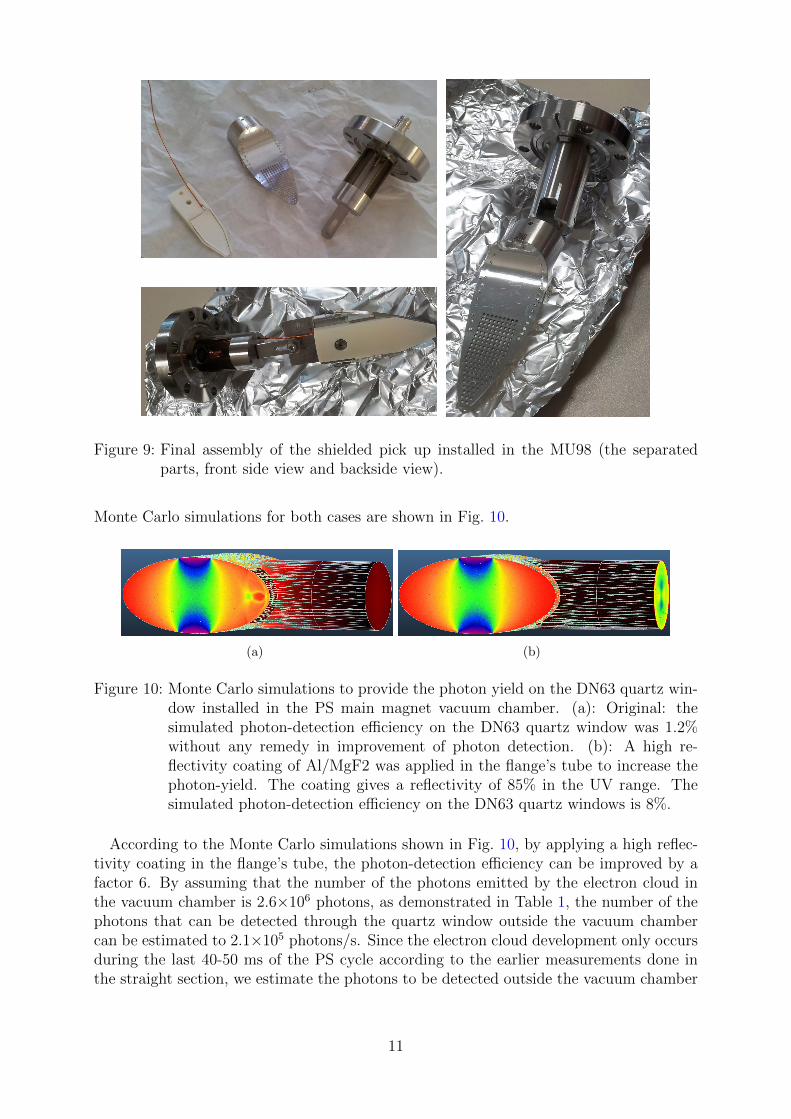
Figure 9: Final assembly of the shielded pick up installed in the MU98 (the separatedparts, front side view and backside view).
Monte Carlo simulations for both cases are shown in Fig. 10.
(a) (b)
Figure 10: Monte Carlo simulations to provide the photon yield on the DN63 quartz win-dow installed in the PS main magnet vacuum chamber. (a): Original: thesimulated photon-detection efficiency on the DN63 quartz window was 1.2%without any remedy in improvement of photon detection. (b): A high re-flectivity coating of Al/MgF2 was applied in the flange’s tube to increase thephoton-yield. The coating gives a reflectivity of 85% in the UV range. Thesimulated photon-detection efficiency on the DN63 quartz windows is 8%.
According to the Monte Carlo simulations shown in Fig. 10, by applying a high reflec-tivity coating in the flange’s tube, the photon-detection efficiency can be improved by afactor 6. By assuming that the number of the photons emitted by the electron cloud inthe vacuum chamber is 2.6×10⁶ photons, as demonstrated in Table 1, the number of thephotons that can be detected through the quartz window outside the vacuum chambercan be estimated to 2.1×10⁵ photons/s. Since the electron cloud development only occursduring the last 40-50 ms of the PS cycle according to the earlier measurements done inthe straight section, we estimate the photons to be detected outside the vacuum chamber
11
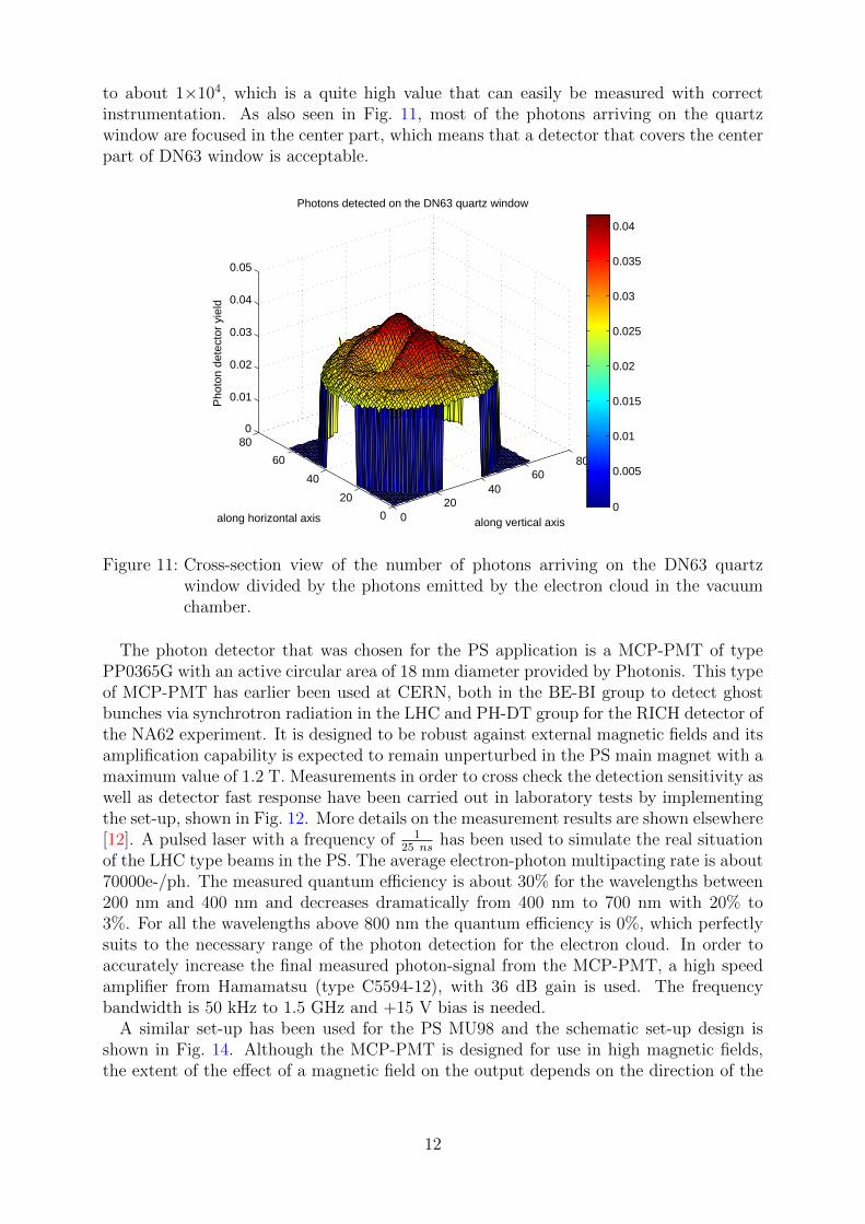
to about 1×10⁴, which is a quite high value that can easily be measured with correctinstrumentation. As also seen in Fig. 11, most of the photons arriving on the quartzwindow are focused in the center part, which means that a detector that covers the centerpart of DN63 window is acceptable.
020
4060
80
0
20
40
60
800
0.01
0.02
0.03
0.04
0.05
along vertical axis
Photons detected on the DN63 quartz window
along horizontal axis
Pho
ton
dete
ctor
yie
ld
0
0.005
0.01
0.015
0.02
0.025
0.03
0.035
0.04
Figure 11: Cross-section view of the number of photons arriving on the DN63 quartzwindow divided by the photons emitted by the electron cloud in the vacuumchamber.
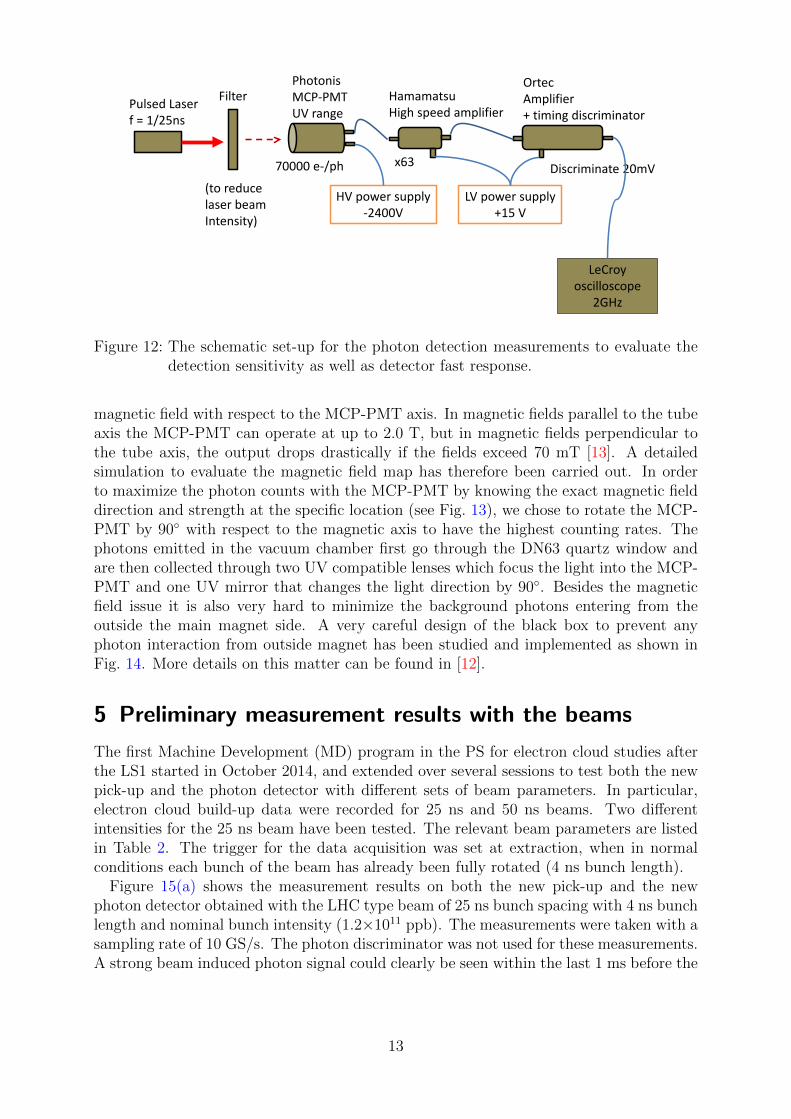
The photon detector that was chosen for the PS application is a MCP-PMT of typePP0365G with an active circular area of 18 mm diameter provided by Photonis. This typeof MCP-PMT has earlier been used at CERN, both in the BE-BI group to detect ghostbunches via synchrotron radiation in the LHC and PH-DT group for the RICH detector ofthe NA62 experiment. It is designed to be robust against external magnetic fields and itsamplification capability is expected to remain unperturbed in the PS main magnet with amaximum value of 1.2 T. Measurements in order to cross check the detection sensitivity aswell as detector fast response have been carried out in laboratory tests by implementingthe set-up, shown in Fig. 12. More details on the measurement results are shown elsewhere[12]. A pulsed laser with a frequency of 1
25 nshas been used to simulate the real situation
of the LHC type beams in the PS. The average electron-photon multipacting rate is about70000e-/ph. The measured quantum efficiency is about 30% for the wavelengths between200 nm and 400 nm and decreases dramatically from 400 nm to 700 nm with 20% to3%. For all the wavelengths above 800 nm the quantum efficiency is 0%, which perfectlysuits to the necessary range of the photon detection for the electron cloud. In order toaccurately increase the final measured photon-signal from the MCP-PMT, a high speedamplifier from Hamamatsu (type C5594-12), with 36 dB gain is used. The frequencybandwidth is 50 kHz to 1.5 GHz and +15 V bias is needed.
A similar set-up has been used for the PS MU98 and the schematic set-up design isshown in Fig. 14. Although the MCP-PMT is designed for use in high magnetic fields,the extent of the effect of a magnetic field on the output depends on the direction of the
12
BI lab set-up
Pulsed Laser f = 1/25ns
Filter Photonis MCP-PMT UV range
70000 e-/ph
Hamamatsu High speed amplifier
x63
(to reduce laser beam Intensity)
Ortec Amplifier + timing discriminator
Discriminate 20mV
LeCroy oscilloscope
2GHz
HV power supply -2400V
LV power supply +15 V
Figure 12: The schematic set-up for the photon detection measurements to evaluate thedetection sensitivity as well as detector fast response.
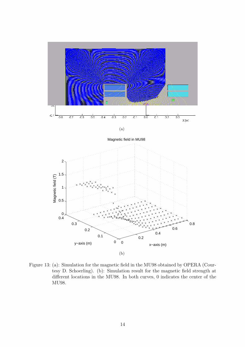
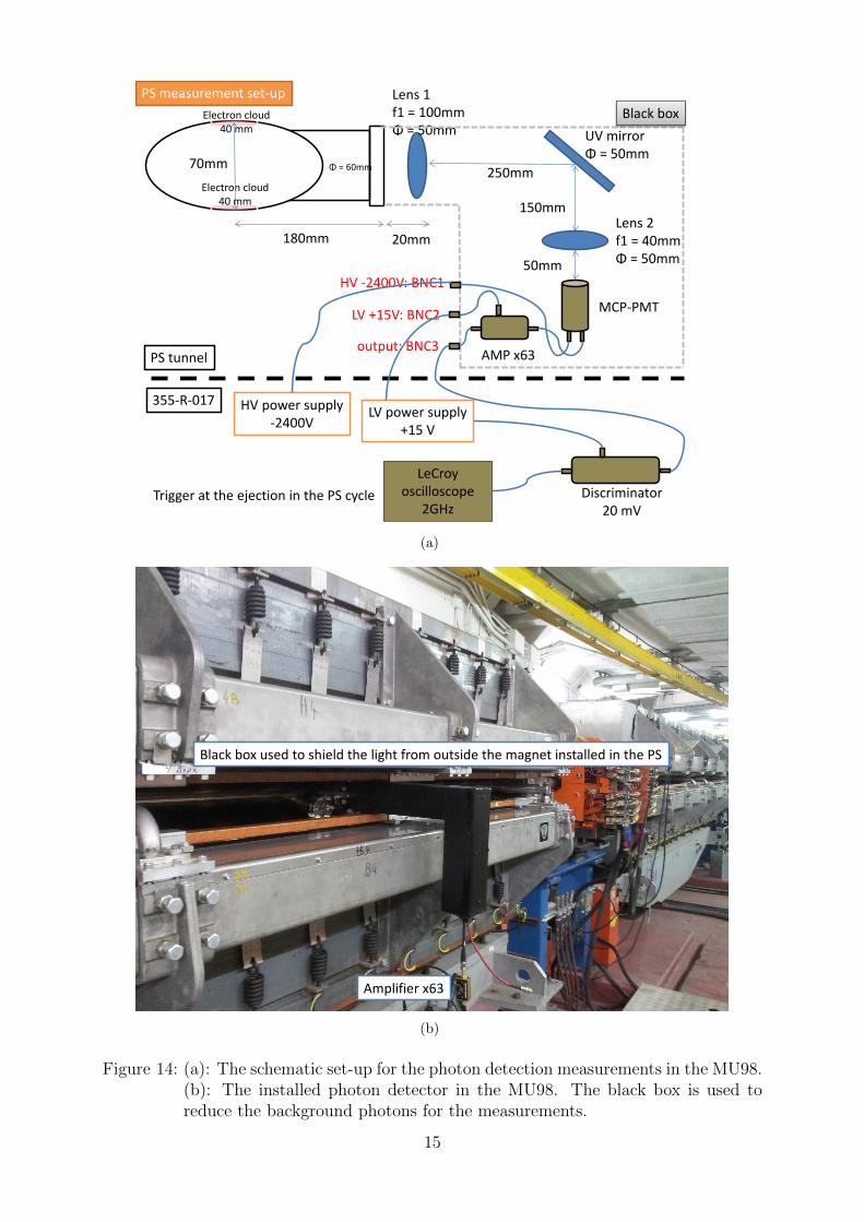
magnetic field with respect to the MCP-PMT axis. In magnetic fields parallel to the tubeaxis the MCP-PMT can operate at up to 2.0 T, but in magnetic fields perpendicular tothe tube axis, the output drops drastically if the fields exceed 70 mT [13]. A detailedsimulation to evaluate the magnetic field map has therefore been carried out. In orderto maximize the photon counts with the MCP-PMT by knowing the exact magnetic fielddirection and strength at the specific location (see Fig. 13), we chose to rotate the MCP-PMT by 90◦ with respect to the magnetic axis to have the highest counting rates. Thephotons emitted in the vacuum chamber first go through the DN63 quartz window andare then collected through two UV compatible lenses which focus the light into the MCP-PMT and one UV mirror that changes the light direction by 90◦. Besides the magneticfield issue it is also very hard to minimize the background photons entering from theoutside the main magnet side. A very careful design of the black box to prevent anyphoton interaction from outside magnet has been studied and implemented as shown inFig. 14. More details on this matter can be found in [12].
5 Preliminary measurement results with the beams
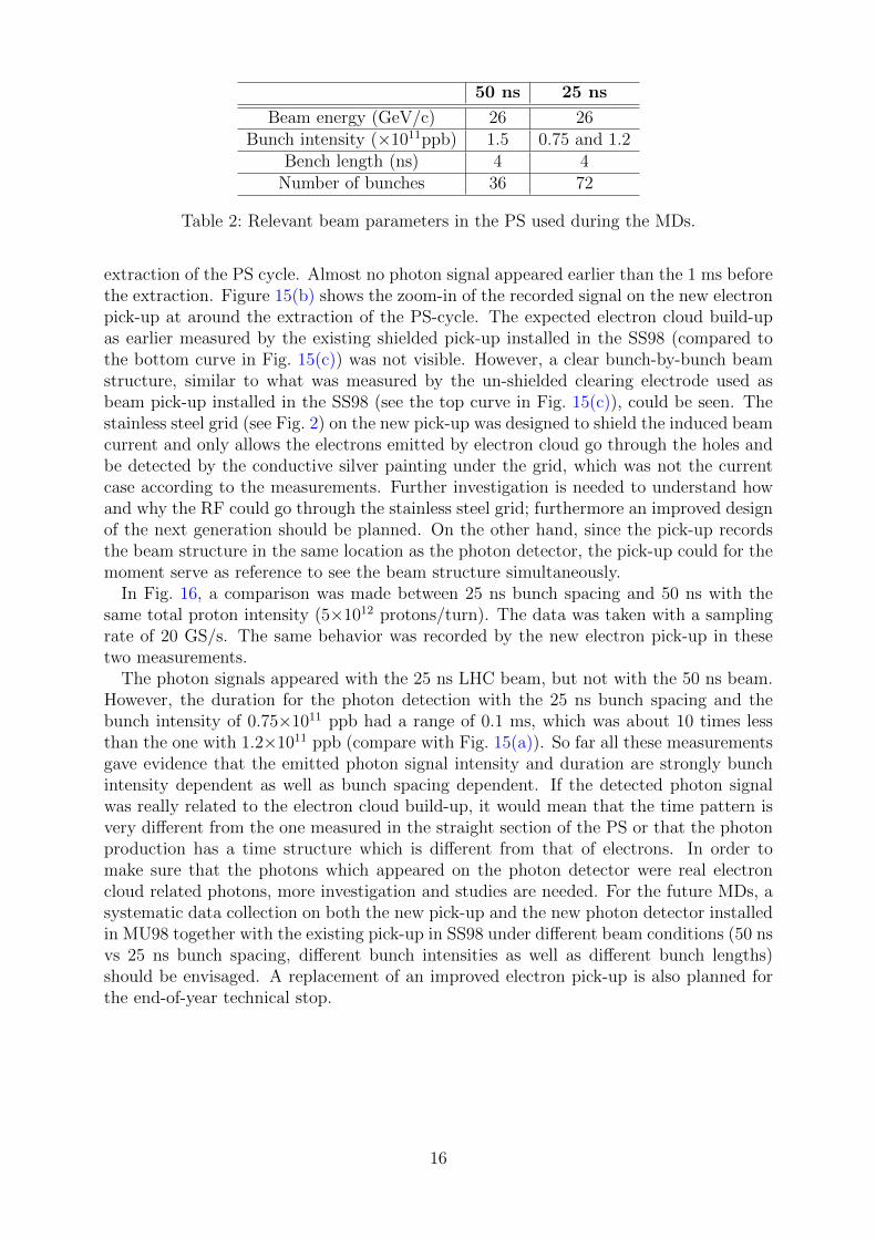
The first Machine Development (MD) program in the PS for electron cloud studies afterthe LS1 started in October 2014, and extended over several sessions to test both the newpick-up and the photon detector with different sets of beam parameters. In particular,electron cloud build-up data were recorded for 25 ns and 50 ns beams. Two differentintensities for the 25 ns beam have been tested. The relevant beam parameters are listedin Table 2. The trigger for the data acquisition was set at extraction, when in normalconditions each bunch of the beam has already been fully rotated (4 ns bunch length).
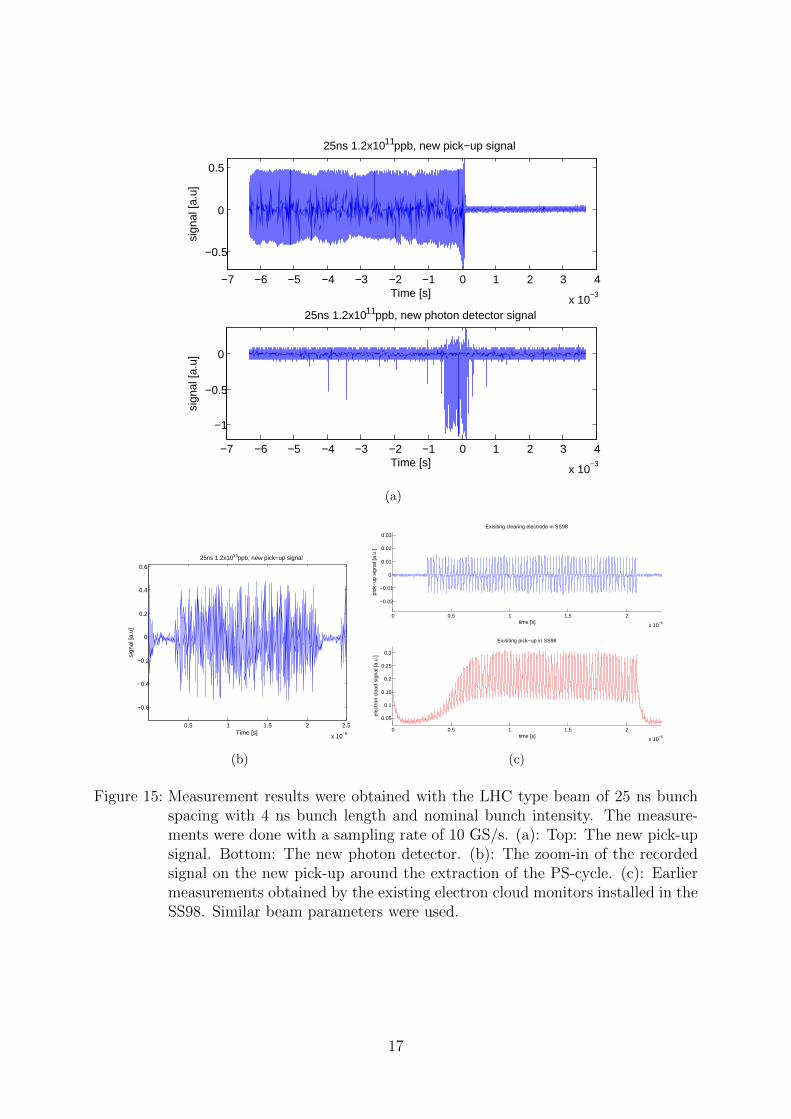
Figure 15(a) shows the measurement results on both the new pick-up and the newphoton detector obtained with the LHC type beam of 25 ns bunch spacing with 4 ns bunchlength and nominal bunch intensity (1.2×10¹¹ ppb). The measurements were taken with asampling rate of 10 GS/s. The photon discriminator was not used for these measurements.A strong beam induced photon signal could clearly be seen within the last 1 ms before the
13
(a)
00.2
0.40.6
0.8
0
0.1
0.2
0.3
0.40
0.5
1
1.5
2
x−axis (m)
Magnetic field in MU98
y−axis (m)
Mag
netic
fiel
d (T
)
(b)
Figure 13: (a): Simulation for the magnetic field in the MU98 obtained by OPERA (Cour-tesy D. Schoerling). (b): Simulation result for the magnetic field strength atdifferent locations in the MU98. In both curves, 0 indicates the center of theMU98.
14
PS measurement set-up
PS tunnel
355-R-017
180mm 20mm
250mm
150mm
50mm
Lens 1 f1 = 100mm Φ = 50mm UV mirror
Φ = 50mm
Lens 2 f1 = 40mm Φ = 50mm
MCP-PMT
AMP x63
Electron cloud 40 mm
Electron cloud 40 mm
70mm Φ = 60mm
HV power supply -2400V
Discriminator 20 mV
LeCroy oscilloscope
2GHz
LV power supply +15 V
HV -2400V: BNC1
LV +15V: BNC2
output: BNC3
Black box
Trigger at the ejection in the PS cycle
(a)
Black box used to shield the light from outside the magnet installed in the PS
Amplifier x63
(b)
Figure 14: (a): The schematic set-up for the photon detection measurements in the MU98.(b): The installed photon detector in the MU98. The black box is used toreduce the background photons for the measurements.
15
50 ns 25 ns
Beam energy (GeV/c) 26 26Bunch intensity (×1011ppb) 1.5 0.75 and 1.2
Bench length (ns) 4 4Number of bunches 36 72
Table 2: Relevant beam parameters in the PS used during the MDs.
extraction of the PS cycle. Almost no photon signal appeared earlier than the 1 ms beforethe extraction. Figure 15(b) shows the zoom-in of the recorded signal on the new electronpick-up at around the extraction of the PS-cycle. The expected electron cloud build-upas earlier measured by the existing shielded pick-up installed in the SS98 (compared tothe bottom curve in Fig. 15(c)) was not visible. However, a clear bunch-by-bunch beamstructure, similar to what was measured by the un-shielded clearing electrode used asbeam pick-up installed in the SS98 (see the top curve in Fig. 15(c)), could be seen. Thestainless steel grid (see Fig. 2) on the new pick-up was designed to shield the induced beamcurrent and only allows the electrons emitted by electron cloud go through the holes andbe detected by the conductive silver painting under the grid, which was not the currentcase according to the measurements. Further investigation is needed to understand howand why the RF could go through the stainless steel grid; furthermore an improved designof the next generation should be planned. On the other hand, since the pick-up recordsthe beam structure in the same location as the photon detector, the pick-up could for themoment serve as reference to see the beam structure simultaneously.
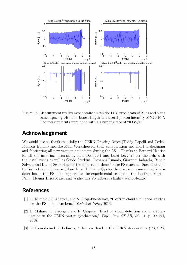
In Fig. 16, a comparison was made between 25 ns bunch spacing and 50 ns with thesame total proton intensity (5×10¹² protons/turn). The data was taken with a samplingrate of 20 GS/s. The same behavior was recorded by the new electron pick-up in thesetwo measurements.
The photon signals appeared with the 25 ns LHC beam, but not with the 50 ns beam.However, the duration for the photon detection with the 25 ns bunch spacing and thebunch intensity of 0.75×10¹¹ ppb had a range of 0.1 ms, which was about 10 times lessthan the one with 1.2×10¹¹ ppb (compare with Fig. 15(a)). So far all these measurementsgave evidence that the emitted photon signal intensity and duration are strongly bunchintensity dependent as well as bunch spacing dependent. If the detected photon signalwas really related to the electron cloud build-up, it would mean that the time pattern isvery different from the one measured in the straight section of the PS or that the photonproduction has a time structure which is different from that of electrons. In order tomake sure that the photons which appeared on the photon detector were real electroncloud related photons, more investigation and studies are needed. For the future MDs, asystematic data collection on both the new pick-up and the new photon detector installedin MU98 together with the existing pick-up in SS98 under different beam conditions (50 nsvs 25 ns bunch spacing, different bunch intensities as well as different bunch lengths)should be envisaged. A replacement of an improved electron pick-up is also planned forthe end-of-year technical stop.
16
−7 −6 −5 −4 −3 −2 −1 0 1 2 3 4
x 10−3
−0.5
0
0.5
25ns 1.2x10¹¹ppb, new pick−up signal
Time [s]
sign
al [a
.u]
−7 −6 −5 −4 −3 −2 −1 0 1 2 3 4
x 10−3
−1
−0.5
0
25ns 1.2x10¹¹ppb, new photon detector signal
Time [s]
sign
al [a
.u]
(a)
0.5 1 1.5 2 2.5
x 10−6
−0.6
−0.4
−0.2
0
0.2
0.4
0.6
25ns 1.2x10¹¹ppb, new pick−up signal
Time [s]
sign
al [a
.u]
(b)
0 0.5 1 1.5 2
x 10−6
−0.02
−0.01
0
0.01
0.02
0.03
time [s]
pick
−up
sig
nal [
a.u.
]
Exisiting clearing electrode in SS98
0 0.5 1 1.5 2
x 10−6
0.05
0.1
0.15
0.2
0.25
0.3
time [s]
elec
tron
clo
ud s
igna
l [a.
u.]
Exisiting pick−up in SS98
(c)
Figure 15: Measurement results were obtained with the LHC type beam of 25 ns bunchspacing with 4 ns bunch length and nominal bunch intensity. The measure-ments were done with a sampling rate of 10 GS/s. (a): Top: The new pick-upsignal. Bottom: The new photon detector. (b): The zoom-in of the recordedsignal on the new pick-up around the extraction of the PS-cycle. (c): Earliermeasurements obtained by the existing electron cloud monitors installed in theSS98. Similar beam parameters were used.
17
−5 −4 −3 −2 −1 0 1
x 10−4
−1
−0.5
0
0.5
125ns 0.75x10¹¹ ppb, new pick−up signal
Time [s]
sign
al [a
.u.]
−5 −4 −3 −2 −1 0 1
x 10−4
−1
−0.5
0
0.5
150ns 1.5x10¹¹ ppb, new pick−up signal
Time [s]
sign
al [a
.u.]
−5 −4 −3 −2 −1 0 1
x 10−4
−1.5
−1
−0.5
0
0.525ns 0.75x10¹¹ ppb, new photon detector signal
Time [s]
sign
al [a
.u.]
−5 −4 −3 −2 −1 0 1
x 10−4
−1.5
−1
−0.5
0
0.550ns 1.5x10¹¹ ppb, new photon detector signal
Time [s]
sign
al [a
.u.]
Figure 16: Measurement results were obtained with the LHC type beam of 25 ns and 50 nsbunch spacing with 4 ns bunch length and a total proton intensity of 5.2×10¹².The measurements were done with a sampling rate of 20 GS/s.
Acknowledgement
We would like to thank especially the CERN Drawing Office (Teddy Capelli and CedricFrancois Eymin) and the Main Workshop for their collaboration and effort in designingand fabricating all new vacuum equipment during the LS1. Thanks to Bernard Henristfor all the inspiring discussions, Paul Demarest and Luigi Leggiero for the help withthe installations as well as Guido Sterbini, Giovanni Rumolo, Giovanni Iadarola, BenoitSalvant and Daniel Schoerling for the simulations done for the PS machine. Special thanksto Enrico Bravin, Thomas Schneider and Thierry Gys for the discussion concerning photo-detection in the PS. The support for the experimental set-ups in the lab from MarcusPalm, Mounir Driss Mensi and Wilhelmus Vollenberg is highly acknowledged.
References
[1] G. Rumolo, G. Iadarola, and S. Rioja-Fuentelsaz, “Electron cloud simulation studiesfor the PS main chambers,” Technical Notes, 2013.
[2] E. Mahner, T. Kroyger, and F. Caspers, “Electron cloud detection and character-ization in the CERN proton synchrotron,” Phys. Rev. ST-AB, vol. 11, p. 094404,2008.
[3] G. Rumolo and G. Iadarola, “Electron cloud in the CERN Accelerators (PS, SPS,
18
LHC),” Joint INFN-CERN-EuCARD-AccNet Workshop on Electron-Cloud Effects,2012.
[4] G. Iadarola, H. Damerau, S. Gilardoni, G. Rumolo, G. Sterbini, C. Y. Vallgren,M. Pivi, and S. Rioja-Fuentelsaz, “Electron cloud studies for the upgrade of theCERN PS,” 4th International Particle Accelerator Conference, 2013.
[5] V. Dose, “VUV isochromat spectroscopy,” Appl. Phys., vol. 14, pp. 117–118, 1977.
[6] N. V. Smith, “Inverse photoemission,” Rep. Prog. Phys., vol. 51, pp. 1227–1294, 1998.
[7] B. Papanicolaou and et. al., “Cathodoluminescence of copper and nickel surfaces,”J. Phys. Chem. Solids, vol. 37, pp. 403–409, 1976.
[8] N. V. Smith, “Inverse photoemission from metal surfaces,” Prog. Surf. Sci., vol. 21,pp. 295–370, 1986.
[9] C. Y. Vallgren, “Cathodoluminescence of various metals and alloys used for acceler-ator vacuum applications,” to be published as ATS/Note TECH, 2014.
[10] P. Borzyak, I. Geguzin, V. Datsyuk, I. Konovalov, Y. A. Kulyupin, and K. Pilipchak,“Recombination light emission by molybdenum bombarded by slow electrons,” Zh.Eksp. Teor, Fiz, vol. 80, pp. 1514–1523, 1981.
[11] T. Schneider and C. David, “NA62 mylar reflection coating with Al/MgF2,”http://ph-news.web.cern.ch/content/na62-mylar-reflection-coating-almgf2, 2013.
[12] H. Neupert and C. Y. Vallgren, “Tests on photocathode setup for PS e-cloud studies,”to be published as ATS/Note TECH, 2014.
[13] S.-O. Flyckt and C. Marmonier, “Photomultiplier tubes (principles & applications),”Photonis, Brive, France, 2002.
19