CERCALG E PASSER - synthes.vo.llnwd.netsynthes.vo.llnwd.net/o16/LLNWMB8/INT Mobile/Synthes...
28
SURGICAL TECHNIQUE CABLE APPLICATION For minimally invasive application of cerclage cables CERCLAGE PASSER Instruments and implants approved by the AO Foundation. This publication is not intended for distribution in the USA.
Transcript of CERCALG E PASSER - synthes.vo.llnwd.netsynthes.vo.llnwd.net/o16/LLNWMB8/INT Mobile/Synthes...
SURGICAL TECHNIQUE CABLE APPLICATION
For minimally invasive application of cerclage cables
CERCLAGE PASSER
Instruments and implants approved by the AO Foundation.This publication is not intended for distribution in the USA.

Image intensifier control
This description alone does not provide sufficient background for direct use of DePuy Synthes products. Instruction by a surgeon experienced in handling these products is highly recommended.
Processing, Reprocessing, Care and MaintenanceFor general guidelines, function control and dismantling of multi-part instruments, as well as processing guidelines for implants, please contact your local sales representative or refer to:http://emea.depuysynthes.com/hcp/reprocessing-care-maintenanceFor general information about reprocessing, care and maintenance of Synthes reusable devices, instrument trays and cases, as well as processing of Synthes non-sterile implants, please consult the Important Information leaflet (SE_023827) or refer to: http://emea.depuysynthes.com/hcp/reprocessing-care-maintenance
Cerclage Passer Surgical Technique DePuy Synthes 1
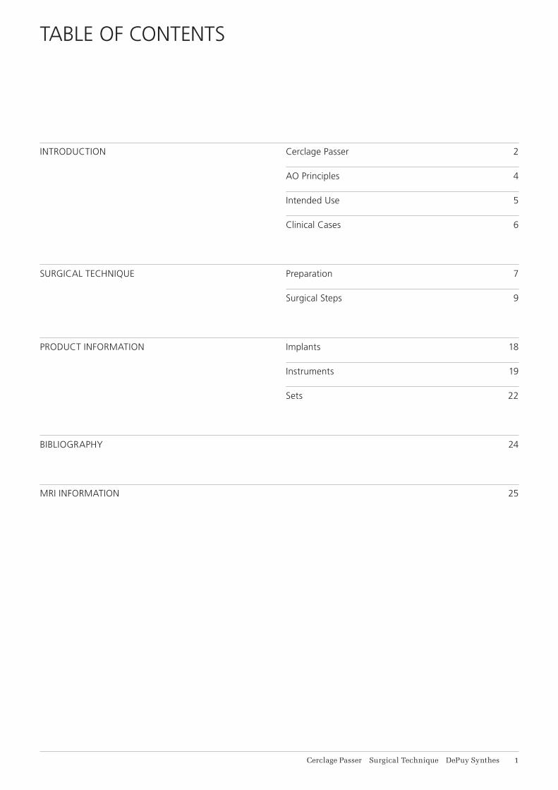
INTRODUCTION Cerclage Passer 2
AO Principles 4
Intended Use 5
Clinical Cases 6
SURGICAL TECHNIQUE Preparation 7
Surgical Steps 9
PRODUCT INFORMATION Implants 18
Instruments 19
Sets 22
BIBLIOGRAPHY 24
MRI INFORMATION 25
TABLE OF CONTENTS
1 DePuy Synthes Cerclage Passer Surgical Technique
CERCLAGE PASSER
FOR MINIMALLY INVASIVE APPLICATION OF CERCLAGE CABLES.
QUICK STEP SURGICAL TECHNIQUE
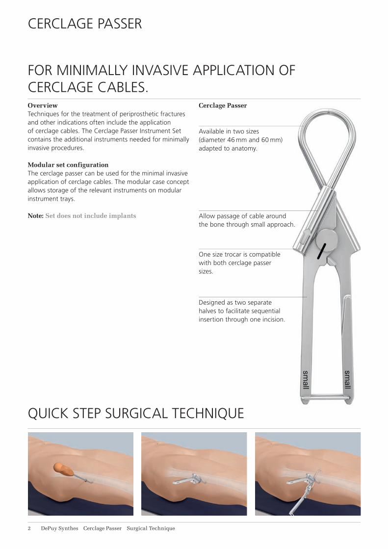
Overview Techniques for the treatment of periprosthetic fractures and other indications often include the application of cerclage cables. The Cerclage Passer Instrument Set contains the additional instruments needed for minimally invasive procedures.
Modular set configurationThe cerclage passer can be used for the minimal invasive application of cerclage cables. The modular case concept allows storage of the relevant instruments on modular instrument trays.
Note: Set does not include implants
Cerclage Passer
Available in two sizes (diameter 46 mm and 60 mm) adapted to anatomy.
Allow passage of cable around the bone through small approach.
One size trocar is compatible with both cerclage passer sizes.
Designed as two separate halves to facilitate sequential insertion through one incision.

Cerclage Passer Surgical Technique DePuy Synthes 1
Prepares the way and facilitates thepassage of the cerclage passer. Available in two sizes that correspond with the bending diameter of the cerclage passer.
Cerclage Tunneling Device
passage of the cerclage passer. Available
bending diameter of the cerclage passer.

1
4
2
3
4_Priciples_03.pdf 1 05.07.12 12:08
4 DePuy Synthes Expert Lateral Femoral Nail Surgical Technique
AO PRINCIPLES
In 1958, the AO formulated four basic principles, which have become the guidelines for internal fixation1, 2.
1 Müller ME, M Allgöwer, R Schneider, H Willenegger. Manual of Internal Fixation. 3rd ed. Berlin Heidelberg New York: Springer. 1991.
2 Rüedi TP, RE Buckley, CG Moran. AO Principles of Fracture Management. 2nd ed. Stuttgart, New York: Thieme. 2007.
Anatomic reductionFracture reduction and fixation to restore anatomical relationships.
Early, active mobilizationEarly and safe mobilization and rehabilitation of the injured part and the patient as a whole.
Stable fixationFracture fixation providing abso-lute or relative stability, as required by the patient, the injury, and the personality of the fracture.
Preservation of blood supplyPreservation of the blood supply to soft tissues and bone by gentle reduction techniques and careful handling.
4 DePuy Synthes Cerclage Passer Surgical Technique
Stable fixationFracture fixation providing absolute or relative stability, as required by the patient, the injury, and the per-sonality of the fracture.
Anatomic reductionFracture reduction and fixation to restore anatomical relationships.
Early, active mobilizationEarly and safe mobilization and rehabilitation of the injured part and the patient as a whole.
Preservation of blood supplyPreservation of the blood supply to soft tissues and bone by gentle reduction techniques and careful handling.
In 1958, the AO formulated four basic principles, which have become the guidelines for internal fixation1,2.
AO PRINCIPLES
1 Müller ME, Allgöwer M, Schneider R, Willenegger H. Manual of Internal Fixation. 3rd ed. Berlin, Heidelberg, New York: Springer. 1991.
2 Rüedi TP, Buckley RE, Moran CG. AO Principles of Fracture Management. 2nd ed. Stuttgart, New York: Thieme. 2007.
Cerclage Passer Surgical Technique DePuy Synthes 5
For general orthopedic trauma surgery involving the application of cerclage cables• Periprosthetic fractures of the femur• Subtrochanteric fractures• Prophylactic banding in total joint replacement• Additional fixation• Temporary reduction
INTENDED USE
6 DePuy Synthes Cerclage Passer Surgical Technique
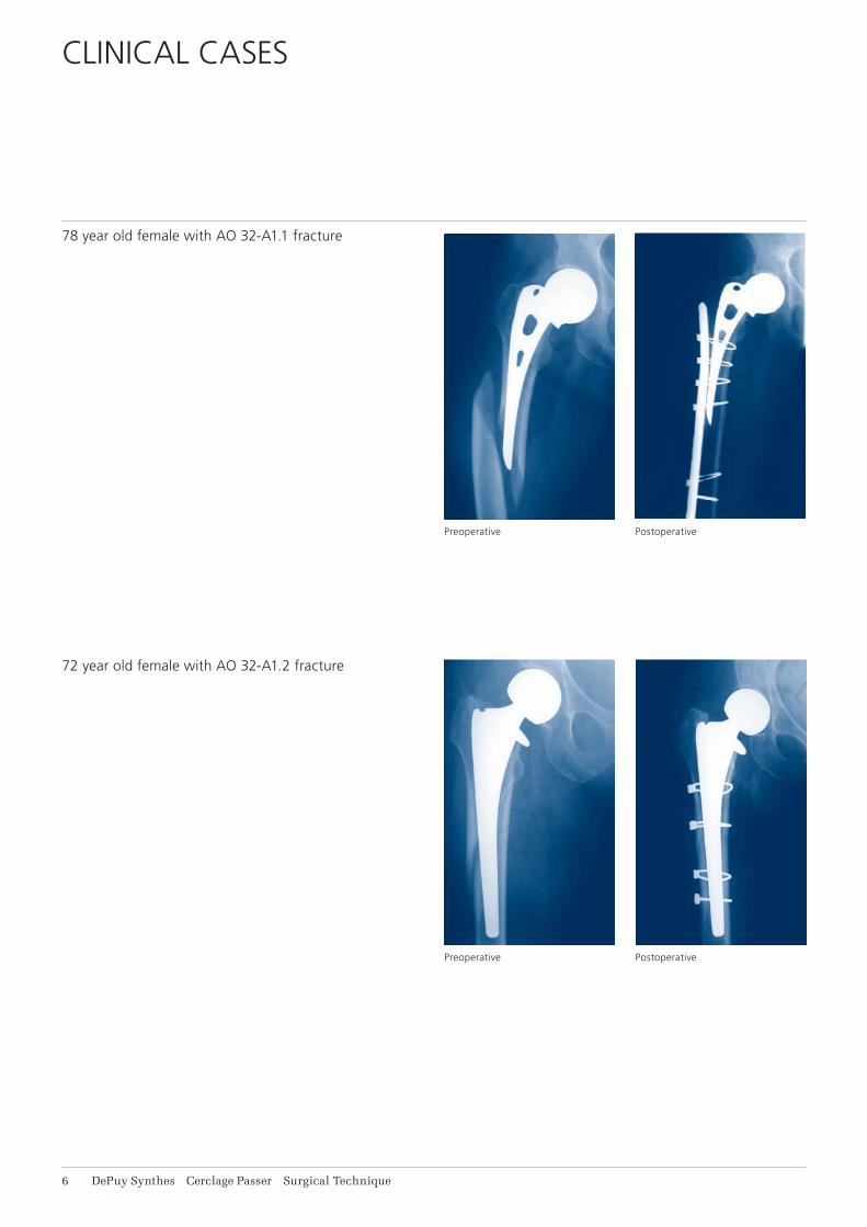
78 year old female with AO 32-A1.1 fracture
72 year old female with AO 32-A1.2 fracture
CLINICAL CASES
Postoperative
Postoperative
Preoperative
Preoperative

Cerclage Passer Surgical Technique DePuy Synthes 1
1 Preparation
Set
01.221.100 Instrument Set for minimally invasive Cable Cerclage
Optional set
188.215 Cable System in Vario Case
Implants
X98.800.01 Cerclage Cable with Crimp, B1.0 mm,2 = X Stainless Steel 4 = X Titanium Alloy (TAN)
298.801.01 Cerclage Cable with Crimp, B1.7 mm, Stainless Steel
611.105.01 Cerclage Cable with Crimp, B1.7 mm, Cobalt-chrome alloy
Precaution: Application of cerclage cables using a minimally invasive (MIS) technique requires a keen understanding of the neurovascular anatomy.
Complete a preoperative radiographic assessment and prepare the preoperative plan. Position the patient according to the respective fracture requirements on a radiolucent operating table.
Complete the closed reduction with traction to minimize anatomic distortion.
PREPARATION
Proximal cut
Diaphyseal cut
Distal cut
Ant.
Ant.
Ant.
Lat.
Lat.
Med.
Med.
Med.
Post.
Post.
Post.
Lat.
Visualization of the neurovascular femur anatomy

8 DePuy Synthes Cerclage Passer Surgical Technique
2Incision and preparation of soft tissue tunnel
Instruments
03.221.002 Cerclage Tunneling Device,B46 mm
03.221.004 Cerclage Tunneling Device,B60 mm
Choose the appropriate size cerclage tunneling device for the field of application and the fracture. Make an in-cision and carefully insert the tunneling device over the periosteum from ventral and dorsal around the bone. Make an incision in the skin and fascia approximately 4–5 cm wide to avoid tension. Ensure the cerclage tun-neling device perforates the fascia directly adjacent to the linea aspera on the dorsal femur.
Preparation of the tunnel is necessary to facilitate the following insertion of the cerclage passer.
Preparation
1
2
Cerclage Passer Surgical Technique DePuy Synthes 9
SURGICAL STEPS
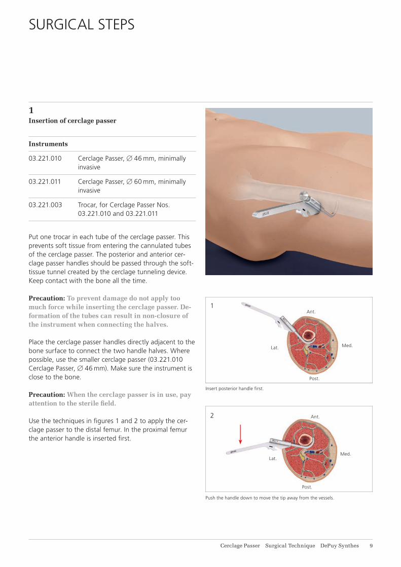
1Insertion of cerclage passer
Instruments
03.221.010 Cerclage Passer,B46 mm, minimally invasive
03.221.011 Cerclage Passer,B60 mm, minimally invasive
03.221.003 Trocar, for Cerclage Passer Nos. 03.221.010 and 03.221.011
Put one trocar in each tube of the cerclage passer. This prevents soft tissue from entering the cannulated tubes of the cerclage passer. The posterior and anterior cer-clage passer handles should be passed through the soft-tissue tunnel created by the cerclage tunneling device. Keep contact with the bone all the time.
Precaution: To prevent damage do not apply too much force while inserting the cerclage passer. De-formation of the tubes can result in non-closure of the instrument when connecting the halves.
Place the cerclage passer handles directly adjacent to the bone surface to connect the two handle halves. Where possible, use the smaller cerclage passer (03.221.010 Cerclage Passer, B46 mm). Make sure the instrument is close to the bone.
Precaution: When the cerclage passer is in use, pay attention to the sterile fi eld.
Use the techniques in fi gures 1 and 2 to apply the cer-clage passer to the distal femur. In the proximal femur the anterior handle is inserted fi rst.
Insert posterior handle first.
Push the handle down to move the tip away from the vessels.
Ant.
Med.
Post.
Lat.
Ant.
Med.
Post.
Lat.
1
2
3
11 DePuy Synthes Cerclage Passer Surgical Technique
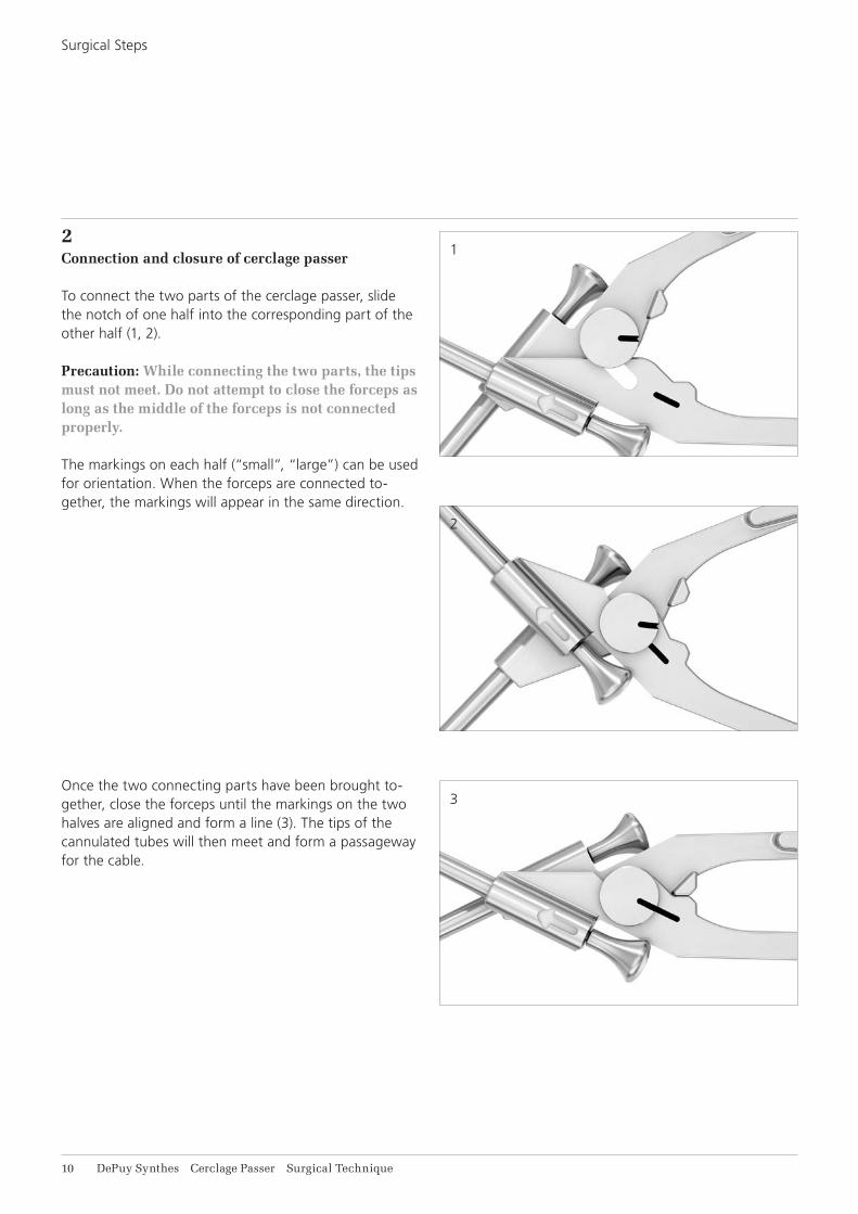
2Connection and closure of cerclage passer
To connect the two parts of the cerclage passer, slide the notch of one half into the corresponding part of the other half (1, 2).
Precaution: While connecting the two parts, the tips must not meet. Do not attempt to close the forceps as long as the middle of the forceps is not connected properly.
The markings on each half (“small”, “large”) can be used for orientation. When the forceps are connected to-gether, the markings will appear in the same direction.
Once the two connecting parts have been brought to-gether, close the forceps until the markings on the two halves are aligned and form a line (3). The tips of the cannulated tubes will then meet and form a passageway for the cable.
Surgical Steps

Cerclage Passer Surgical Technique DePuy Synthes 11
To position the cerclage passer for closure, use the corre-sponding technique per femur segment. Maintain con-tact with the bone throughout the procedure.
Proximal cut: Lift the handle to close instrument posteriorly.
Diaphyseal cut: Lift the handle to close instrument posteriorly.
Distal cut: Push the handle down to move the tip away from the vessels.
Ant.
Med.
Post.
Lat.
Post.
Ant.
Med.Lat.
Ant.
Med.
Post.
Lat.
Proximal cut
Diaphyseal cut
Distal cut
11 DePuy Synthes Cerclage Passer Surgical Technique
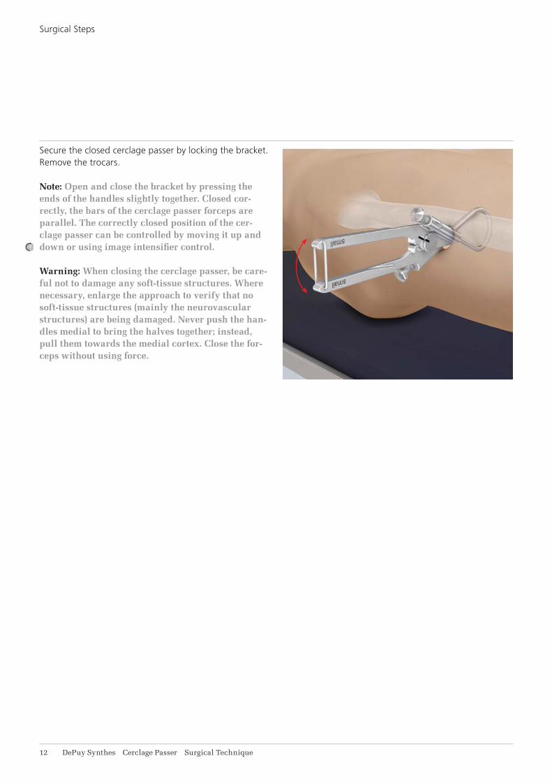
Secure the closed cerclage passer by locking the bracket. Remove the trocars.
Note: Open and close the bracket by pressing the ends of the handles slightly together. Closed cor-rectly, the bars of the cerclage passer forceps are parallel. The correctly closed position of the cer-clage passer can be controlled by moving it up and down or using image intensifier control.
Warning: When closing the cerclage passer, be care-ful not to damage any soft-tissue structures. Where necessary, enlarge the approach to verify that no soft-tissue structures (mainly the neurovascular structures) are being damaged. Never push the han-dles medial to bring the halves together; instead, pull them towards the medial cortex. Close the for-ceps without using force.
Surgical Steps
Cerclage Passer Surgical Technique DePuy Synthes 11
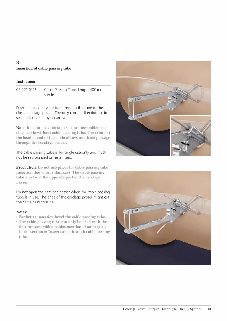
3Insertion of cable passing tube
Instrument
03.221.012S Cable Passing Tube, length 400 mm, sterile
Push the cable passing tube through the tube of the closed cerclage passer. The only correct direction for in-sertion is marked by an arrow.
Note: It is not possible to pass a pre-assembled cer-clage cable without cable passing tube. The crimp at the beaded end of the cable allows no direct passage through the cerclage passer.
The cable passing tube is for single use only and must not be reprocessed or resterilized.
Precaution: Do not use pliers for cable passing tube insertion due to tube damages. The cable passing tube must exit the opposite part of the cerclage passer.
Do not open the cerclage passer when the cable passing tube is in use. The ends of the cerclage passer might cut the cable passing tube.
Notes:• For better insertion bevel the cable passing tube.• The cable passing tube can only be used with the
four pre-assembled cables mentioned on page 15 in the section 5: Insert cable through cable passing tube.
14 DePuy Synthes Cerclage Passer Surgical Technique
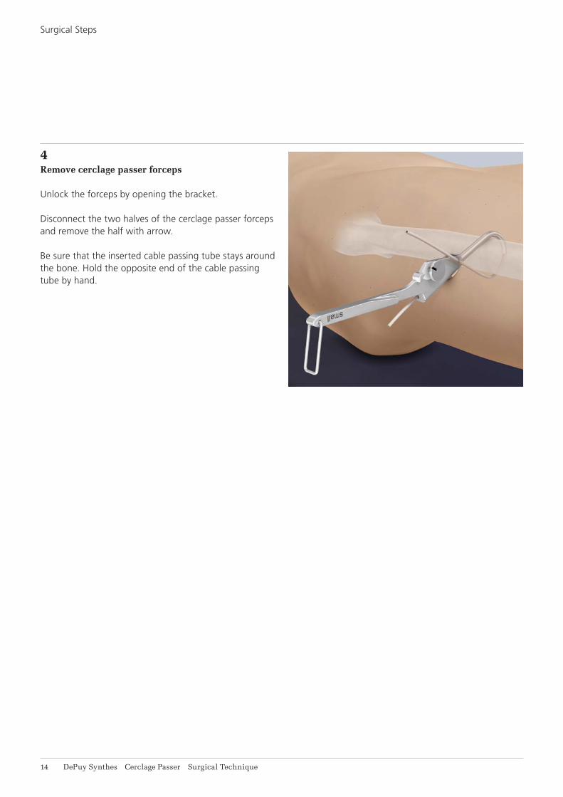
4Remove cerclage passer forceps
Unlock the forceps by opening the bracket.
Disconnect the two halves of the cerclage passer forceps and remove the half with arrow.
Be sure that the inserted cable passing tube stays around the bone. Hold the opposite end of the cable passing tube by hand.
Surgical Steps

Cerclage Passer Surgical Technique DePuy Synthes 15
5Insert cable through cable passing tube
Implants
298.800.01 Cerclage Cable with CrimpB1.0 mm, Stainless Steel
298.801.01 Cerclage Cable with CrimpB1.7 mm, Stainless Steel
498.800.01 Cerclage Cable with CrimpB1.0 mm, Titanium Alloy (TAN)
611.105.01 Cable with CrimpB1.7 mm, Cobalt-chrome alloy
Select the cable according to the application and frac-ture.
Push the end without bead through the cable passing tube without the cerclage passer until the cable exits. Remove the other half of the cerclage passer.
Precaution: If the cerclage cable is used in contact with other implants (e.g. LCP broad curved plate), consider the correct combination of metals.
16 DePuy Synthes Cerclage Passer Surgical Technique
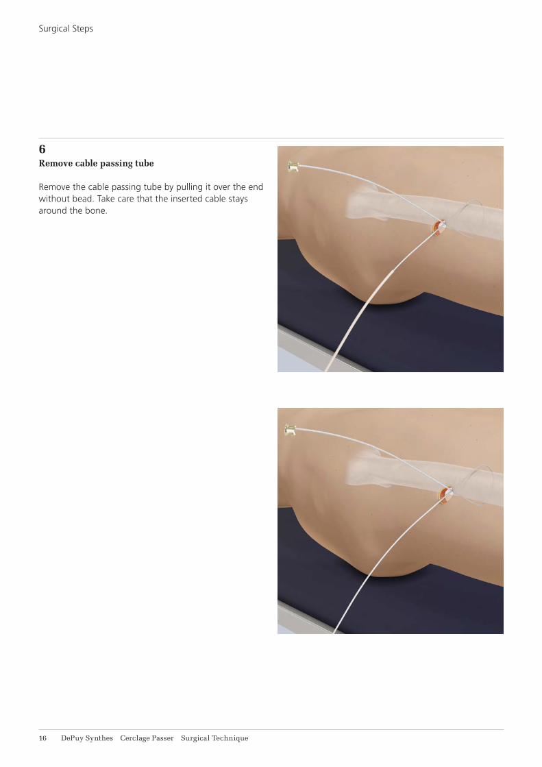
6Remove cable passing tube
Remove the cable passing tube by pulling it over the end without bead. Take care that the inserted cable stays around the bone.
Surgical Steps

Cerclage Passer Surgical Technique DePuy Synthes 11
7Tightening and fixation of cable
For further procedure, please refer to the Cable System surgical technique [DSEM/TRM/0615/0398(1)] page 8, step 4A.
8Cut cable
Instrument
03.607.513 Front Cutter
Cut the loose end of the cable using the front cutter. Position the cutting jaws very close to the crimp, and make the cut in one action to produce a clean cut. Ensure that the adjacent cerclage cables do not get damaged.

18 DePuy Synthes Cerclage Passer Surgical Technique
X98.800.01 Cerclage Cable with Crimp B1.0 mm
X98.800.01S Cerclage Cable with Crimp B1.0 mm, sterile
298.801.01 Cerclage Cable with Crimp B1.7 mm, Stainless Steel
298.801.01S Cerclage Cable with Crimp B1.7 mm, Stainless Steel, sterile
611.105.01 Cerclage Cable with Crimp, B1.7 mm, Cobalt-chrome alloy
611.105.01S Cerclage Cable with Crimp B1.7 mm, Cobalt-chrome alloy, sterile
498.806 TRD – Trochanter Reattachment Device, small, for Cable System, Titanium Alloy (TAN)
498.806S TRD – Trochanter Reattachment Device, small, for Cable System, Titanium Alloy (TAN), sterile
498.807 TRD – Trochanter Reattachment Device, large, for Cable System, Titanium Alloy (TAN)
498.807S TRD – Trochanter Reattachment Device, large, for Cable System, Titanium Alloy (TAN), sterile
IMPLANTS
X=2: Stainless SteelX=4: Titanium Alloy (TAN)
Cerclage Passer Surgical Technique DePuy Synthes 19
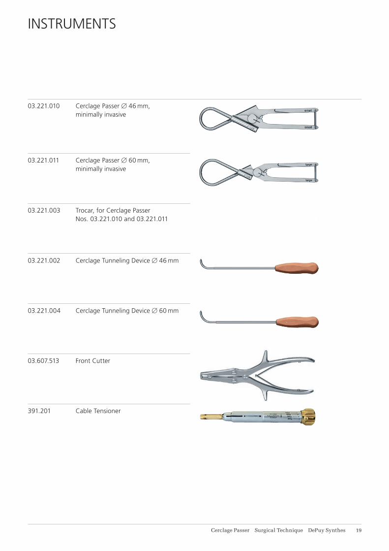
INSTRUMENTS
03.221.010 Cerclage PasserB46 mm, minimally invasive
03.221.011 Cerclage PasserB60 mm, minimally invasive
03.221.003 Trocar, for Cerclage Passer Nos. 03.221.010 and 03.221.011
03.221.002 Cerclage Tunneling DeviceB46 mm
03.221.004 Cerclage Tunneling DeviceB60 mm
03.607.513 Front Cutter
391.201 Cable Tensioner
11 DePuy Synthes Cerclage Passer Surgical Technique
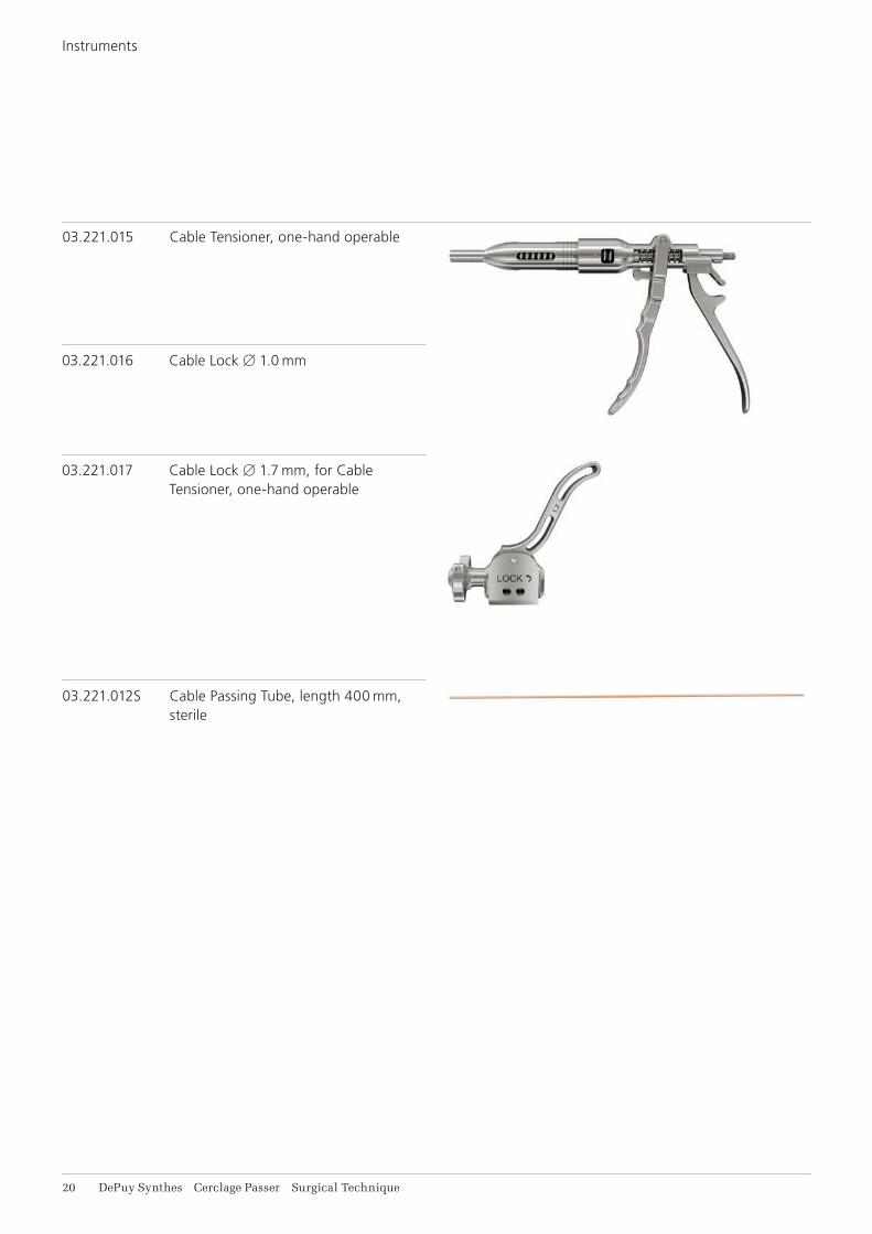
03.221.012S Cable Passing Tube, length 400 mm, sterile
03.221.015 Cable Tensioner, one-hand operable
03.221.016 Cable Lock B1.0 mm
03.221.017 Cable Lock B1.7 mm, for Cable Tensioner, one-hand operable
Instruments
Cerclage Passer Surgical Technique DePuy Synthes 11
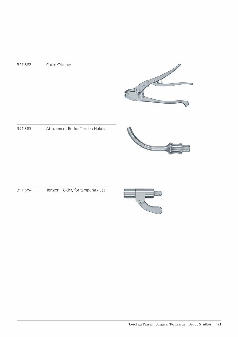
391.882 Cable Crimper
391.883 Attachment Bit for Tension Holder
391.884 Tension Holder, for temporary use
11 DePuy Synthes Cerclage Passer Surgical Technique
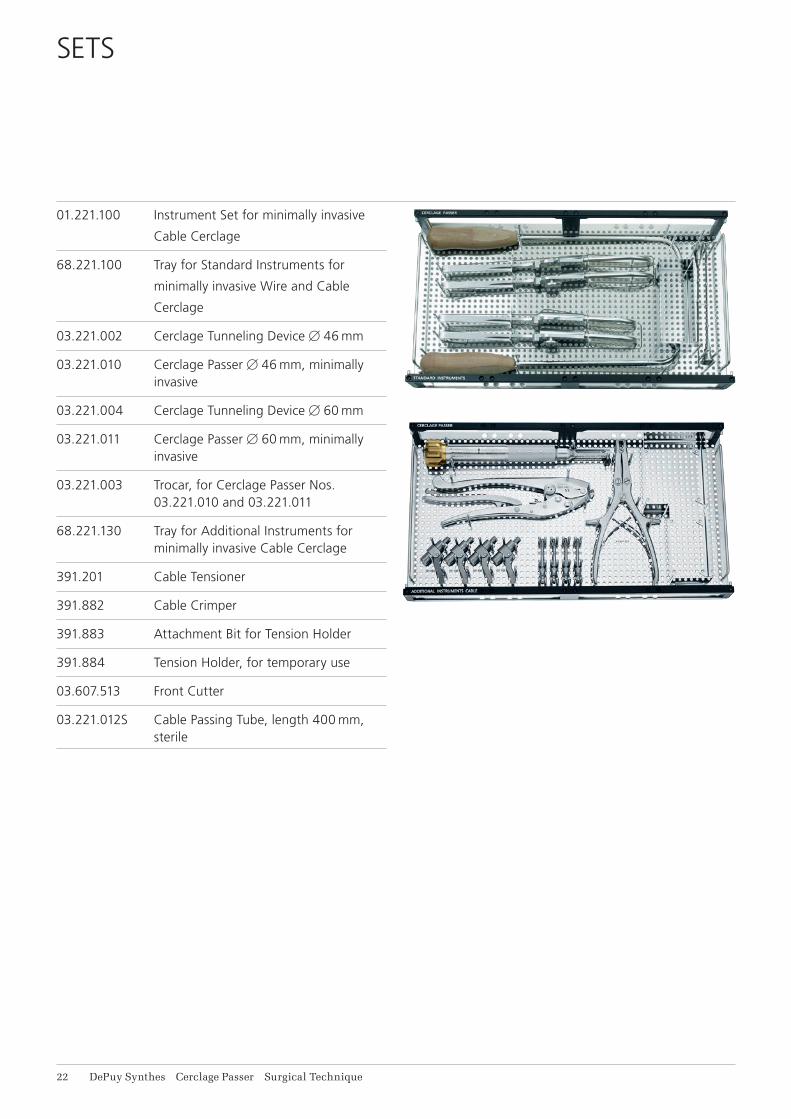
SETS
01.221.100 Instrument Set for minimally invasive
Cable Cerclage
68.221.100 Tray for Standard Instruments for
minimally invasive Wire and Cable
Cerclage
03.221.002 Cerclage Tunneling DeviceB46 mm
03.221.010 Cerclage PasserB46 mm, minimally invasive
03.221.004 Cerclage Tunneling DeviceB60 mm
03.221.011 Cerclage PasserB60 mm, minimally invasive
03.221.003 Trocar, for Cerclage Passer Nos. 03.221.010 and 03.221.011
68.221.130 Tray for Additional Instruments for minimally invasive Cable Cerclage
391.201 Cable Tensioner
391.882 Cable Crimper
391.883 Attachment Bit for Tension Holder
391.884 Tension Holder, for temporary use
03.607.513 Front Cutter
03.221.012S Cable Passing Tube, length 400 mm, sterile

Cerclage Passer Surgical Technique DePuy Synthes 11
Additionally available in sterile
03.221.012S Cable Passing Tube, length 400 mm, sterile
Additionally available
68.221.120 Labelling Plate for Instrument Set for minimally invasive Cerclage, for Vario Case
68.000.101 Lid for Modular Tray, size 1/1
519.400 Cleaning Brush, for Compact Air Drive, Power Drive and Colibri
Vario Case components
689.507 Lid (Stainless Steel), size 1/1, for Vario Case
689.510 Vario Case, Framing, size 1/1, height 126 mm

14 DePuy Synthes Cerclage Passer Surgical Technique
BIBLIOGRAPHY
Schmidt AH, Kyle RF (2002) Periprosthetic fractures of the femur. Orthop Clin North Am: 143–152
Tong G, Bavonratanavech S (2006) Minimally Invasive Plate Osteosynthesis (MIPO): Concepts and cases pre-sented by the AO East Asia

Cerclage Passer Surgical Technique DePuy Synthes 15
MRI INFORMATION
Torque, Displacement and Image Artifacts according to ASTM F 2213-06, ASTM F 2052-06e1 and ASTM F 2119-07Non-clinical testing of worst case scenario in a 3 T MRI system did not reveal any relevant torque or displace-ment of the construct for an experimentally measured local spatial gradient of the magnetic field of 3.69 T/m. The largest image artifact extended approximately 169 mm from the construct when scanned using the Gradient Echo (GE). Testing was conducted on a 3 T MRI system.
Radio-Frequency-(RF-)induced heating according to ASTM F 2182-11aNon-clinical electromagnetic and thermal testing of worst case scenario lead to peak temperature rise of 9.5 °C with an average temperature rise of 6.6 °C (1.5 T) and a peak temperature rise of 5.9 °C (3 T) under MRI Conditions using RF Coils (whole body averaged specific absorption rate [SAR] of 2 W/kg for 6 minutes [1.5 T] and for 15 minutes [3 T]).
Precautions: The above mentioned test relies on non-clinical testing. The actual temperature rise in the patient will depend on a variety of factors beyond the SAR and time of RF application. Thus, it is recommended to pay particular attention to the following points: • It is recommended to thoroughly monitor patients
undergoing MR scanning for perceived tempera-ture and/or pain sensations.
• Patients with impaired thermoregulation or temperature sensation should be excluded from MR scanning procedures.
• Generally, it is recommended to use a MR system with low field strength in the presence of conduc-tive implants. The employed specific absorption rate (SAR) should be reduced as far as possible.
• Using the ventilation system may further contrib-ute to reduce temperature increase in the body.
01230123
Synthes GmbHEimattstrasse 34436 OberdorfSwitzerlandTel: +41 61 965 61 11Fax: +41 61 965 66 00www.depuysynthes.com
Not all products are currently available in all markets.
This publication is not intended for distribution in the USA.
All surgical techniques are available as PDF files at www.depuysynthes.com/ifu ©
DeP
uy S
ynth
es T
raum
a, a
div
isio
n of
Syn
thes
Gm
bH. 2
016.
A
ll rig
hts
rese
rved
. 03
6.00
0.76
8 D
SE
M/T
RM
/051
5/03
95(1
) 06
/16