Ceramic Touch Induction - Amazon S3 · PDF fileCeramic Touch Induction Control Hob ... This...
28
User Guide Ceramic Touch Induction Control Hob LAM1800 Part No: 0835502001 Date: 07/02/2017 www.howdens.com/appliance-registration
Transcript of Ceramic Touch Induction - Amazon S3 · PDF fileCeramic Touch Induction Control Hob ... This...

User Guide
Ceramic Touch Induction Control Hob
LAM1800
Part No: 0835502001 Date: 07/02/2017
www.howdens.com/appliance-registration

Thank you for buying this British-built appliance from us.
This user guide book is designed to help you through each step of owning your new product. Please read it carefully before you start using your appliance, as we have endeavored to answer as many questions as possible, and provide you with as much support as we can. General information, spares and service information is available from our website.
If you should find something missing from your product or have any questions that are not covered in this user guide, please contact us (see contact information inside the front cover).
European DirectivesAs a producer and a supplier of cooking appliances we are committed to the protection of the environ-
ment and are in the compliance with the WEEE directive. All our electric products are labelled accordingly with the crossed out wheeled bin symbol. This indicates, for disposal purposes at end of life, that these products must be taken to a recognized collection points, such as local authority sites/local recycling centres.
This appliance Complies with European Community Directives (CE) for household and similar electrical appliances and Gas appliances where applicable.
This appliance conforms to European Directive regarding Eco design requirements for energy-related products. Our policy is one of constant development and improvement, therefore we cannot guarantee the strict accuracy of all of our illustrations and specifications - changes may have been made subse-quent to publishing.
Disposal of Packaging MaterialThe packaging materials used with this appliance can be recycled. Please dispose of the packaging materials in the appropriate container at your local waste disposal facilities.
UK ONLY GAS WARNING:If you smell gas, Do not try to light any appliance. Do not touch any electrical switch.
Call the Gas Emergency Help line at 0800 111999
INTRODUCTION
WARNING• If the hob surface is cracked, broken or shattered, switch off the
appliance to avoid the possibility of electric shock and call for a service engineer’s visit.
• The appliance and its accessible parts become hot during use. Care should be taken to avoid touching heating elements. Children less than 8 years of age shall be kept away unless continuously supervised. This appliance can be used by children aged from 8 years and above and persons with reduced physical sensory or mental capabilities or lack of experience and knowledge if they have been given supervision or instruction concerning the use of the appliance in a safe way and understand the hazards involved. Children shall not play with the appliance. Cleaning and user maintenance shall not be made by children without supervision.
• Do not use a steam cleaner on any cooking range, hob or oven appliance.
• Metallic objects such a knives, forks, spoons and lids should not be placed on the hob surface since they can get hot.
• After use, switch off the hob element by its control and do not rely on the pan detector.
• The appliance is not intended to be operated by means of an external timer or separate control system.
• Unattended cooking on a hob with fat or oil can be dangerous and may result in fire.
• NEVER try to extinguish a fire with water, but switch off the appliance and then cover the flame with a lid or damp cloth.
• Danger of fire: Do not store items on the cooking surfaces.• Only use hob guards designed by the manufacturer of the cooking
appliance or indicated by the manufacturer of the appliance in the instructions for use as suitable or hob guards incorporated in the appliance. The use of inappropriate hob guards can cause accidents.
CAUTION• The cooking process has to be supervised. A short term cooking
process has to be supervised continuously.
SAFETY
• Fire Safety AdviceIf you do have a fire in the kitchen, don’t take any risks - get everyone out of your home and call the Fire Brigade.
Ifyouhaveanelectricalfireinthekitchen:• Pull the plug out, or switch off the power at the fuse box - this may be enough to stop the fire imme-
diately • Smother the fire with a fire blanket, or use a dry powder or carbon dioxide extinguisher • Remember: never use water on an electrical or cooking oil fire.
• Other Safety Advice• Servicing should be carried out only by authorised personnel.• There is a risk of electric shock, so always make sure you have turned off and unplugged your
appliance before starting. Always allow the product to cool down before you change a bulb.• This appliance must be earthed.• The appliance must never be disconnected from the mains supply during use, as this will seriously
affect the safety and performance, particularly in relation to surface temperatures becoming hot and gas operated parts not working efficiently.
• GAS WARNING! - If you smell gas: Do not try to light any appliance, Do not touch any electrical switch. Contact your local gas supplier immediately.

USING YOUR APPLIANCE
Getting to know your product Note: Your appliance layout may differ depending on the model.
Hob
Control panel
2
3
4
5
1 COOK ZONE KEYS
INDIVIDUAL COOK ZONE DISPLAYS
POWER DOWN KEY (-)
POWER UP KEY (+)
ON/OFF KEY6 TIMER DISPLAYS
1
2
6
2 2
33 4
5
Left hand rearRight hand rear
Right hand frontLeft hand front

Overview
Function Description SymbolPower Level Once a cook zone is selected, a power level can
be set to a low or high temperature. 1-9
Residual Heat
After use, the cooking surface remains hot and the residual heat symbol will be displayed. As it cools, the residual heat symbol will disappear from the
display.
Pan detection
If no pan or an unsuitable pan is detected on an activated cook zone, the pan detection symbol will
be displayed.Suitable pans - cast iron, metals with magnetic
properties. Non-suitable pans - copper, stainless steel, aluminium, glass, ceramic, terra-cotta.
Pan overheat
To prevent the cookware from overheating, the hob will reduce the power or switch off all cook
zones depending if a power level or power boost is in use.
N/A
Booster function
The booster function temporarily increases the power to a cook zone allowing for a faster heat up
time. It will deactivate automatically after 10minutes or if a lower power level is selected.
Child lock Child lock can be activated to stop the hob from being accidentally turned on.

Switching the appliance On
1 Press On/Off key to activate the appliance
Note: If a cook zone is not selected in 10 seconds, the hob will turn off automatically.
Switching the appliance off
Touch the On/Off key for 1 second. A beep sounds and all the heaters will switch off.
Switching on an individual hob cook zone
1 Choose cook zone
2 Use the up or down key to choose power level
When the cook zone selection is finished after 10 seconds, a beep sounds and all the heater displays that were dimmed show the power levels with normal brightness.
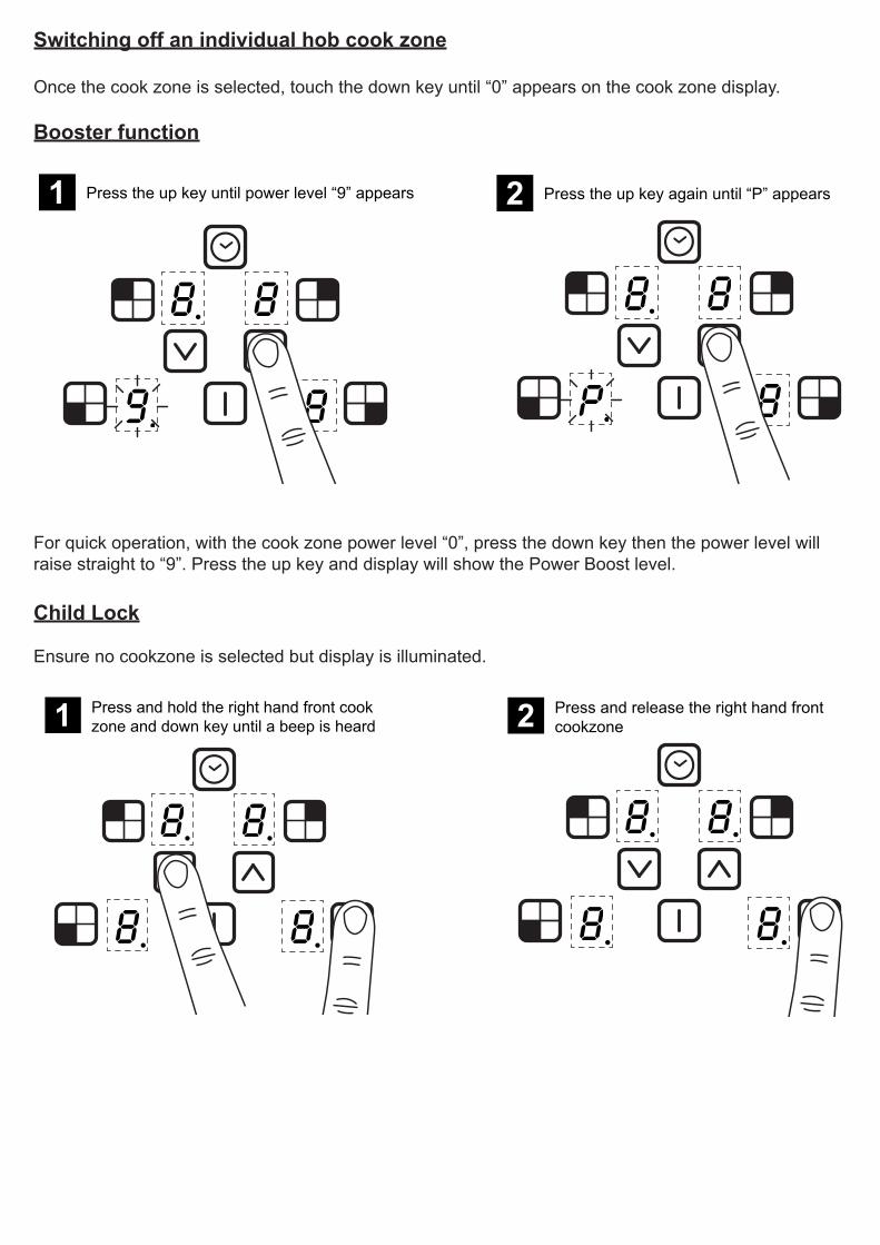
Switching off an individual hob cook zone
Once the cook zone is selected, touch the down key until “0” appears on the cook zone display. Booster function
1 Press the up key until power level “9” appears
2 Press the up key again until “P” appears
For quick operation, with the cook zone power level “0”, press the down key then the power level will raise straight to “9”. Press the up key and display will show the Power Boost level.
Child Lock
Ensure no cookzone is selected but display is illuminated.
1 Press and hold the right hand front cookzone and down key until a beep is heard
2 Press and release the right hand frontcookzone

3 Remove fingers and “L” will appear on all cookzone displays
4 Press the on/off key to switch the appliance off
5 Press the on/off key to switch the appliance on
When you now switch on the hob “L” will appear in all the cook zone displays. The child lock feature will be activated until you switch this feature off.

De-activate child lock
1 Press the on/off key to switch the appliance on
2 Press and hold the right hand front cookzone and down key
3 Remove fingers and touch the down key.The child lock should switch off
4 Press the on/off key to switch the appliance on.Child lock is now deactivated.
Note: When you now switch on the hob “0” will be displayed in all cook zone displays, the hob can now be used normally.

Setting the minute minder
Ensure no cooking zones have been selected.
1 Touch and hold the up and down keys together.The display will show “00”
2 Press the up or down keys to set the time
The maximum time that can be set is 99 minutes.
When the time is up, the timer display will flash and a beep will be heard. Touch any key to stop.
Note: If the hob is turned off, the minute minder operation is shown by flashing dots on the display.
To modify or cancel the minute minder
Repeat the following steps to ‘Setting the minute minder’, to adjust the time.
Setting back to zero will cancel the minute minder.
Setting the timer auto switch off
Ensure power level is already set before selecting timer.
1 Select the cook zone
2 Touch and hold the up and downs keys together.The display will show “00”

3 Press the up or down keys to set the time
4 Once set, the timed cook zone display willshow a dot
The timer indicator in the display stops flashing and is not displayed. Operation of a timer is shown by a stationary dot in the cook zone display for the timed cook zone.
To check the remaining time, select the timed cook zone, and hold the down and up keys together. This will show the timer display.
When the time is up, the timer display will flash and then will automatically switch off. The timed cook zone display will then show a flashing dot. Touch any key to stop the beeping.
To modify or cancel the minute minder
Repeat the following steps to ‘Setting the timer auto switch off’, to set the time for additional cook zones or to adjust the time.
Setting back to “00” will cancel the timer.
If multiple timers have been set
Ensure that a cooking zone has not been selected.
1 Touch and hold the up and downs keys together.
2 Touch the up or down keys to display timed cookzones (active cook zone times are cycled clockwise)
Note: If the minute minder has also been set it will be displayed first. In this case other timed cooking zones are shown by a stationary dot in the cook zone display.

Pan Detection
The above “U” symbol appears when a zone has been activated but no pan has been placed on the cook zone. If the “U” symbol does not disappear when a pan is placed on the zone it indicates that the pan is not suitable for induction cooking.
When a pan is taken off a zone, the hob automatically reduces the power, and only switches back on when you replace the pan.
Please be aware that the pans can make a noise during cooking. This is caused by vibration due to the passage of energy from the hob to the pan.
Residual heat indicators
This feature not only warns you against hot surfaces but also indicates that there is residual heat which can be used as temporary warm zone.
Note: The cook zone itself does not heat up, but the ceramic glass does get hot because of the hot pan conducting heat back onto the hob glass.

Auto stand by
The hob will automatically switch off if left (with pan) on for an extended period of time, see maximum running times below.
Power Level Maximum Operation Time hours
1 82 63 54 55 46 1.57 1.58 1.59 1.5
P (Power Boost) 1.5
Hob status
ApplianceErrors Fault Description Action
ER03 and permanent tone
Continuous button actuation; control switches off after 10
secondsClean the user interface.
E2 Over temperature Allow system to cool
E3
1. Pot/pan not suitable, example Loss of magnetic properties because of temperature at
bottom of pot.2. Power of cooking zones
permanently exceeded
1. This error is reset after 30 seconds; the cooking zone can be used again. The pot/pan must be removed if the fault keeps reoccur-
ring.2. The power unit must be replaced if the er-ror continues to be displayed even when no
pot/pan is present on the cooking zone.
E/H Invariable resistor fault Induction module must be cool

CLEANING YOUR APPLIANCEDo’s Note: Always switch off your appliance and allow it to cool down before you clean any part of it.Note: Please take extra care when cleaning over the symbols on the control panel, as this can lead to them fading.
H
Tips: Some foods can mark or damage the metal or paint work e.g.; Vinegar, fruit juices and salt. Always clean food spillages as soon as possible.
Dont’s
IT IS IMPORTANT TO CLEAN YOUR APPLIANCE REGULARLY AS A BUILD UP OF FAT CANAFFECT IT’S PERFORMANCE OR DAMAGE IT AND MAY INVALIDATE YOUR GUARANTEE.
• Undiluted bleaches• Chloride products
• Warm, soapy water • Wipe with damp cloth• Dry with a soft cloth
• Clean, wrung out cloth
• Wire Wool• Abrasive cleaners• Nylon pads• Steam cleaners
Do not place in the dishwasher:• Cast iron griddle• Pan supports

Before you start please read the instructions. Planning your installation will save you time and effort.
FAILURE TO INSTALL APPLIANCES CORRECTLY IS DANGEROUS AND COULD LEAD TO PROSECUTION.
Please take care when handling - we recommend the use of protective gloves during installation.
Installation should only be carried out by a competent electrician / qualified technician. We recommend that the appliance is connected by a competent person who is a member of a “Competent Person Scheme” who will comply with the required local regulations. In regions where applicable, please retain your certificate of compliance
Our policy is one of constant development and improvement, therefore we cannot guarantee the strict accuracy of all of our illustrations and specifications. Changes may have been made subsequent to publishing.
Please keep to the following points most carefully;
Although every care has been taken to ensure this appliance has no burrs, or sharp edges, we recom-mend that you wear protective gloves when installing and moving this appliance. This will prevent injury. The hob should not be fitted above a washing machine, a fridge or a freezer.
Wall surfaces above the work surface and in the immediate vicinity of the cooking hob must be heat resistant. Laminated surfaces and the adhesive used, must be heat resistant in order to avoid any dam-age.
The space for air circulation, located underneath and at the back of the hob improves its reliability by ensuring that it will cool down, efficiently.
Installations should be carried out in line with the National Regulations applicable for this product type.Make sure that the air inlets through the ventilator grids underneath the hob are never blocked. An air outlet of 5mm underneath work surface is required.
INSTALLATION INSTRUCTIONS
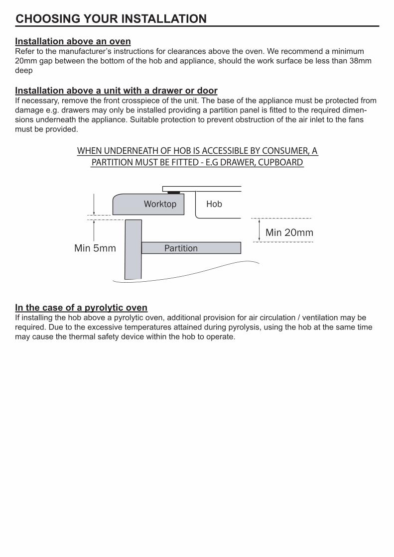
Installation above an ovenRefer to the manufacturer’s instructions for clearances above the oven. We recommend a minimum 20mm gap between the bottom of the hob and appliance, should the work surface be less than 38mm deep Installation above a unit with a drawer or doorIf necessary, remove the front crosspiece of the unit. The base of the appliance must be protected from damage e.g. drawers may only be installed providing a partition panel is fitted to the required dimen-sions underneath the appliance. Suitable protection to prevent obstruction of the air inlet to the fans must be provided.
Worktop
Min 20mmPartician
Hob
Partition
WHEN UNDERNEATH OF HOB IS ACCESSIBLE BY CONSUMER, APARTITION MUST BE FITTED - E.G DRAWER, CUPBOARD
Min 5mm
In the case of a pyrolytic ovenIf installing the hob above a pyrolytic oven, additional provision for air circulation / ventilation may be required. Due to the excessive temperatures attained during pyrolysis, using the hob at the same time may cause the thermal safety device within the hob to operate.
CHOOSING YOUR INSTALLATION
DIMENSIONS AND CLEARANCES
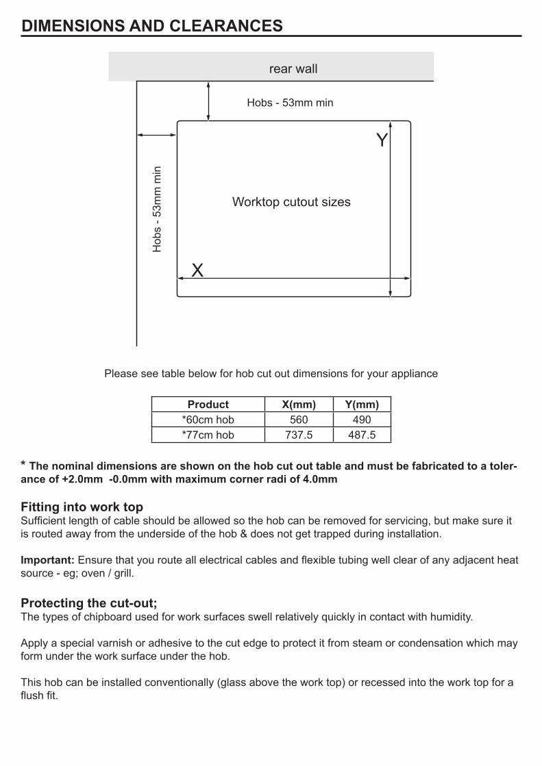
Worktop cutout sizes
Hob
s - 5
3mm
min
Hobs - 53mm min
X
Y
rear wall
Please see table below for hob cut out dimensions for your appliance
Product X(mm) Y(mm)*60cm hob 560 490*77cm hob 737.5 487.5
* The nominal dimensions are shown on the hob cut out table and must be fabricated to a toler-ance of +2.0mm -0.0mm with maximum corner radi of 4.0mm
Fitting into work topSufficient length of cable should be allowed so the hob can be removed for servicing, but make sure it is routed away from the underside of the hob & does not get trapped during installation.
Important: Ensure that you route all electrical cables and flexible tubing well clear of any adjacent heat source - eg; oven / grill.
Protecting the cut-out;The types of chipboard used for work surfaces swell relatively quickly in contact with humidity.
Apply a special varnish or adhesive to the cut edge to protect it from steam or condensation which may form under the work surface under the hob.
This hob can be installed conventionally (glass above the work top) or recessed into the work top for a flush fit.
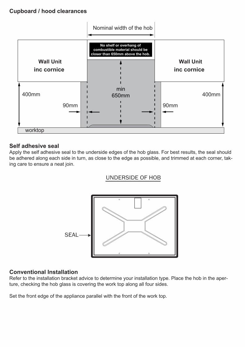
Cupboard / hood clearances
Nominal width of the hob
90mm
Wall Unit Wall Unit
400mm
No shelf or overhang ofcombustible material should be
closer than 650mm above the hob.
90mm
400mmmin
650mm
worktop
Self adhesive sealApply the self adhesive seal to the underside edges of the hob glass. For best results, the seal should be adhered along each side in turn, as close to the edge as possible, and trimmed at each corner, tak-ing care to ensure a neat join.
SEAL
UNDERSIDE OF HOB
Conventional InstallationRefer to the installation bracket advice to determine your installation type. Place the hob in the aper-ture, checking the hob glass is covering the work top along all four sides.
Set the front edge of the appliance parallel with the front of the work top.
inc corniceinc cornice
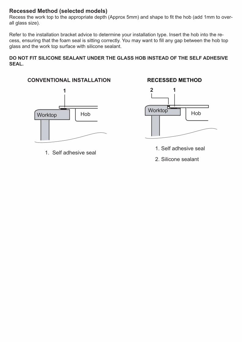
Recessed Method (selected models)Recess the work top to the appropriate depth (Approx 5mm) and shape to fit the hob (add 1mm to over-all glass size).
Refer to the installation bracket advice to determine your installation type. Insert the hob into the re-cess, ensuring that the foam seal is sitting correctly. You may want to fill any gap between the hob top glass and the work top surface with silicone sealant. DO NOT FIT SILICONE SEALANT UNDER THE GLASS HOB INSTEAD OF THE SELF ADHESIVE SEAL.
1. Self adhesive seal
Worktop Hob
CONVENTIONAL INSTALLATION
1
1
Worktop Hob
RECESSED METHOD
1. Self adhesive seal
2. Silicone sealant
2 1
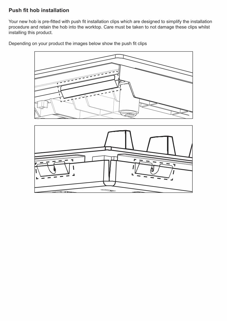
Pushfithobinstallation
Your new hob is pre-fitted with push fit installation clips which are designed to simplify the installation procedure and retain the hob into the worktop. Care must be taken to not damage these clips whilst installing this product.
Depending on your product the images below show the push fit clips
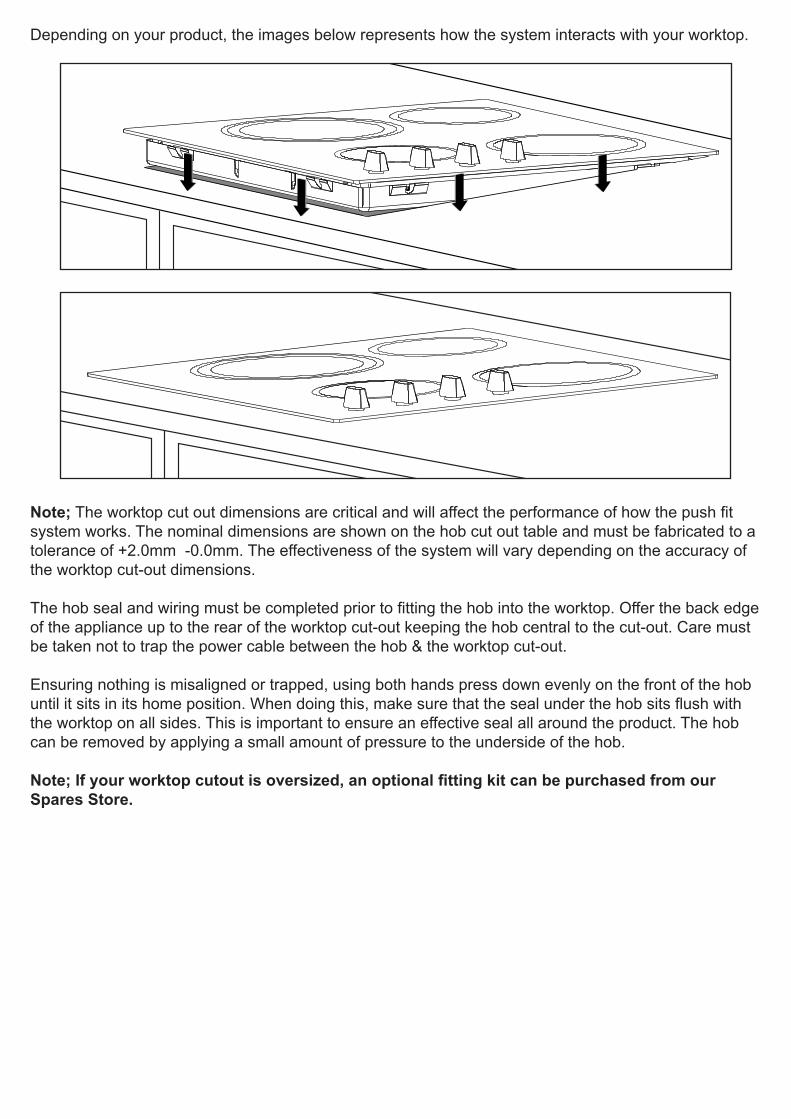
Depending on your product, the images below represents how the system interacts with your worktop.
Note; The worktop cut out dimensions are critical and will affect the performance of how the push fit system works. The nominal dimensions are shown on the hob cut out table and must be fabricated to a tolerance of +2.0mm -0.0mm. The effectiveness of the system will vary depending on the accuracy of the worktop cut-out dimensions.
The hob seal and wiring must be completed prior to fitting the hob into the worktop. Offer the back edge of the appliance up to the rear of the worktop cut-out keeping the hob central to the cut-out. Care must be taken not to trap the power cable between the hob & the worktop cut-out.
Ensuring nothing is misaligned or trapped, using both hands press down evenly on the front of the hob until it sits in its home position. When doing this, make sure that the seal under the hob sits flush with the worktop on all sides. This is important to ensure an effective seal all around the product. The hob can be removed by applying a small amount of pressure to the underside of the hob.
Note;Ifyourworktopcutoutisoversized,anoptionalfittingkitcanbepurchasedfromourSpares Store.
This appliance must be earthed. Only connect to the electrical mains terminal with the power switched off. The electrical mains terminal is live.
Loose and inappropriate connections can make the terminal overheat.
A device must be provided in the electrical installation which allows the appliance to be disconnected from the mains at all poles with a contact opening of at least 3mm.
We recommend that the appliance is connected by a competent person who is a member of a “Compe-tent Person Scheme” who will comply with the required local regulations.
Ensure that you route all mains electrical cables well away from any adjacent heat source, such as an oven or grill.
For UK installation the hob is pre-fitted with a cable HO5V2V2-F 2.5mm2
CONNECT TO THE ELECTRICITY SUPPLY
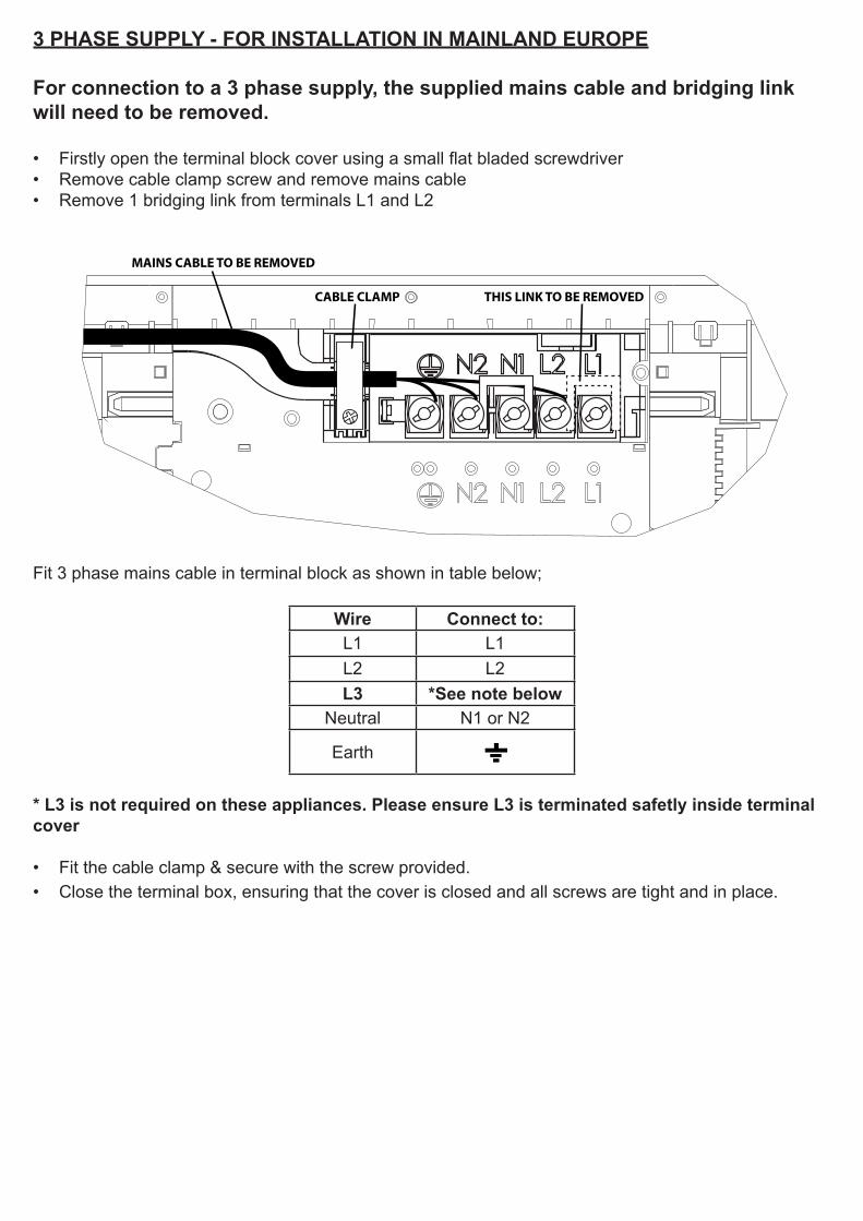
3 PHASE SUPPLY - FOR INSTALLATION IN MAINLAND EUROPE
For connection to a 3 phase supply, the supplied mains cable and bridging link will need to be removed.
• Firstly open the terminal block cover using a small flat bladed screwdriver• Remove cable clamp screw and remove mains cable• Remove 1 bridging link from terminals L1 and L2
MAINS CABLE TO BE REMOVED
CABLE CLAMP THIS LINK TO BE REMOVED
Fit 3 phase mains cable in terminal block as shown in table below;
Wire Connect to:L1 L1L2 L2L3 *See note below
Neutral N1 or N2
Earth
* L3 is not required on these appliances. Please ensure L3 is terminated safetly inside terminalcover
• Fit the cable clamp & secure with the screw provided.• Close the terminal box, ensuring that the cover is closed and all screws are tight and in place.
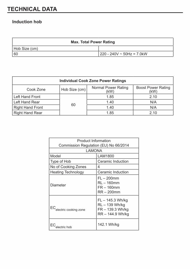
Individual Cook Zone Power Ratings
Cook Zone Hob Size (cm) Normal Power Rating (kW)
Boost Power Rating (kW)
Left Hand Front
60
1.85 2.10Left Hand Rear 1.40 N/ARight Hand Front 1.40 N/ARight Hand Rear 1.85 2.10
Induction hob
TECHNICAL DATA
Max. Total Power RatingHob Size (cm)60 220 - 240V ~ 50Hz = 7.0kW
Product InformationCommission Regulation (EU) No 66/2014
LAMONAModel LAM1800Type of Hob Ceramic InductionNo of Cooking Zones 4Heating Technology Ceramic Induction
Diameter
FL – 200mmRL – 160mmFR – 160mmRR – 200mm
ECelectric cooking zone
FL – 145.3 Wh/kgRL – 139 Wh/kgFR – 139.3 Wh/kgRR – 144.9 Wh/kg
ECelectric hob142.1 Wh/kg

Product Guarantee Details (UK Only)Your appliance has the benefit of a comprehensive manufacturer’s guaranteewhich covers the cost of breakdown repairs. (Details of which are shown on your Proof of purchase Document).
• Any claim during the period of the guarantee MUST BE ACCOMPANIED BY THE PROOF OF PURCHASE.
• The product must be correctly installed and operated in accordance with the manufacturer’s instructions and used for normal domestic purposes.
• This guarantee does not cover accidental damage, misuse or alterations which are likely to affect the product.
• The guarantee is invalid if the product is tampered with, or repaired by any unauthorised person. (The guarantee in no way affects your statutory or legal right)
What to do if you need to report a problem.
Please ensure you have ready:
• The product’s model and serial numbers.• Howdens Proof of Purchase Document.• Your full contact details.
Call the Depot number on your Proof of Purchase Document supplied with the product / kitchen.orCall the LAMONA Service Line on 0845 00 60 006
*Product installed within a domestic kitchen or a non-domestic kitchen where 8 or fewer people are using the appliance.
Wheretofindthemodeland serial number onyour machine.
On the right-hand edgeof the door.
Product serial number(Place sticker here)
ISSUE V2 070217