CERAMAX® CERAMIC TOTAL HIP SYSTEM
48
CERAMAX ® CERAMIC TOTAL HIP SYSTEM SURGICAL TECHNIQUE
Transcript of CERAMAX® CERAMIC TOTAL HIP SYSTEM
CERAMAX® CERAMIC TOTAL HIP SYSTEM
SURGICAL TECHNIQUE
Caution: Refer to the Compatibility Guide on page 40 for important information when ordering compatible components for the CERAMAX Ceramic Total Hip System.
Surgical Technique CERAMAX Ceramic Total Hip System 3
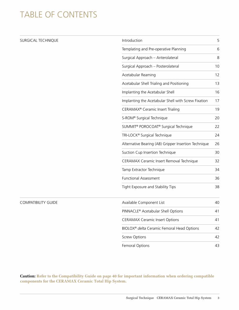
TABLE OF CONTENTS
SURGICAL TECHNIQUE Introduction 5
Templating and Pre-operative Planning 6
Surgical Approach – Anterolateral 8
Surgical Approach – Posterolateral 10
Acetabular Reaming 12
Acetabular Shell Trialing and Positioning 13
Implanting the Acetabular Shell 16
Implanting the Acetabular Shell with Screw Fixation 17
CERAMAX® Ceramic Insert Trialing 19
S-ROM® Surgical Technique 20
SUMMIT® POROCOAT® Surgical Technique 22
TRI-LOCK® Surgical Technique 24
Alternative Bearing (AB) Gripper Insertion Technique 26
Suction Cup Insertion Technique 30
CERAMAX Ceramic Insert Removal Technique 32
Tamp Extractor Technique 34
Functional Assessment 36
Tight Exposure and Stability Tips 38
COMPATIBILITY GUIDE Available Component List 40
PINNACLE® Acetabular Shell Options 41
CERAMAX Ceramic Insert Options 41
BIOLOX® delta Ceramic Femoral Head Options 42
Screw Options 42
Femoral Options 43
Hip reconstruction has become a successful answer for degenerative hip disease in a more demanding patient population. In addition, hip replacement can provide mobility and pain relief to patients with hip osteoarthritis or posttraumatic arthritis. Experience with total hip arthroplasty has resulted in a more comprehensive understanding of hip anatomy and biomechanics and advances in surgical technique. These advances have allowed the development of more efficient instrumentation and increasingly sophisticated implant design.
The CERAMAX® Ceramic Total Hip System primary surgical technique has been developed in consultation with an experienced surgeon design team and provides the surgeon with general guidance when utilizing this system.
SURGICAL TECHNIQUE
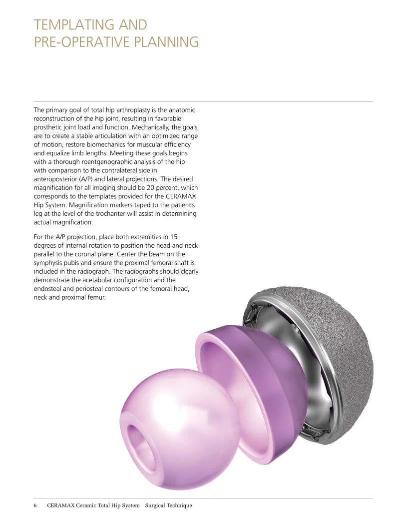
The primary goal of total hip arthroplasty is the anatomic reconstruction of the hip joint, resulting in favorable prosthetic joint load and function. Mechanically, the goals are to create a stable articulation with an optimized range of motion, restore biomechanics for muscular efficiency and equalize limb lengths. Meeting these goals begins with a thorough roentgenographic analysis of the hip with comparison to the contralateral side in anteroposterior (A/P) and lateral projections. The desired magnification for all imaging should be 20 percent, which corresponds to the templates provided for the CERAMAX Hip System. Magnification markers taped to the patient’s leg at the level of the trochanter will assist in determining actual magnification.
For the A/P projection, place both extremities in 15 degrees of internal rotation to position the head and neck parallel to the coronal plane. Center the beam on the symphysis pubis and ensure the proximal femoral shaft is included in the radiograph. The radiographs should clearly demonstrate the acetabular configuration and the endosteal and periosteal contours of the femoral head, neck and proximal femur.
TEMPLATING ANDPRE-OPERATIVE PLANNING
6 CERAMAX Ceramic Total Hip System Surgical Technique
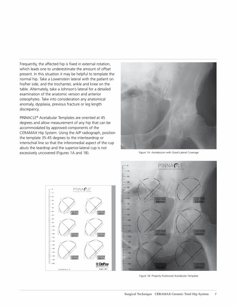
Figure 1A: Acetabulum with Good Lateral Coverage
Figure 1B: Properly Positioned Acetabular Template
Frequently, the affected hip is fixed in external rotation, which leads one to underestimate the amount of offset present. In this situation it may be helpful to template the normal hip. Take a Lowenstein lateral with the patient on his/her side, and the trochanter, ankle and knee on the table. Alternately, take a Johnson’s lateral for a detailed examination of the anatomic version and anterior osteophytes. Take into consideration any anatomical anomaly, dysplasia, previous fracture or leg length discrepancy.
PINNACLE® Acetabular Templates are oriented at 45 degrees and allow measurement of any hip that can be accommodated by approved components of the CERAMAX Hip System. Using the A/P radiograph, position the template 35-45 degrees to the interteardrop or interischial line so that the inferomedial aspect of the cup abuts the teardrop and the superior-lateral cup is not excessively uncovered (Figures 1A and 1B).
Surgical Technique CERAMAX Ceramic Total Hip System 7
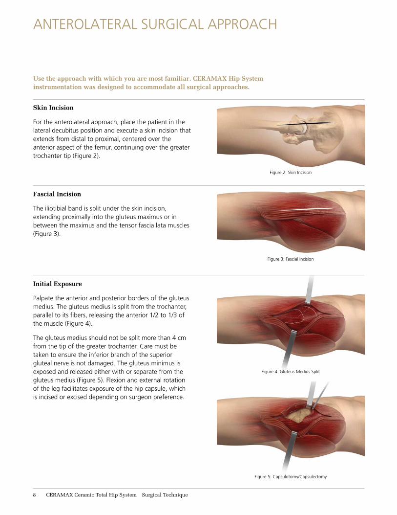
Fascial Incision
The iliotibial band is split under the skin incision, extending proximally into the gluteus maximus or in between the maximus and the tensor fascia lata muscles (Figure 3).
Initial Exposure
Palpate the anterior and posterior borders of the gluteus medius. The gluteus medius is split from the trochanter, parallel to its fibers, releasing the anterior 1/2 to 1/3 of the muscle (Figure 4).
The gluteus medius should not be split more than 4 cm from the tip of the greater trochanter. Care must be taken to ensure the inferior branch of the superior gluteal nerve is not damaged. The gluteus minimus is exposed and released either with or separate from the gluteus medius (Figure 5). Flexion and external rotation of the leg facilitates exposure of the hip capsule, which is incised or excised depending on surgeon preference.
Skin Incision
For the anterolateral approach, place the patient in the lateral decubitus position and execute a skin incision that extends from distal to proximal, centered over the anterior aspect of the femur, continuing over the greater trochanter tip (Figure 2).
ANTEROLATERAL SURGICAL APPROACH
Figure 2: Skin Incision
Figure 4: Gluteus Medius Split
Figure 5: Capsulotomy/Capsulectomy
Use the approach with which you are most familiar. CERAMAX Hip System instrumentation was designed to accommodate all surgical approaches.
Figure 3: Fascial Incision
8 CERAMAX Ceramic Total Hip System Surgical Technique
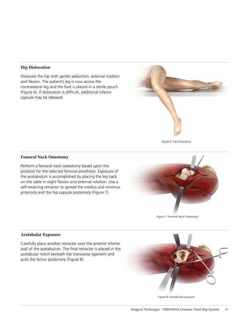
Femoral Neck Osteotomy
Perform a femoral neck osteotomy based upon the protocol for the selected femoral prosthesis. Exposure of the acetabulum is accomplished by placing the leg back on the table in slight flexion and external rotation. Use a self-retaining retractor to spread the medius and minimus anteriorly and the hip capsule posteriorly (Figure 7).
Acetabular Exposure
Carefully place another retractor over the anterior inferior wall of the acetabulum. The final retractor is placed in the acetabular notch beneath the transverse ligament and pulls the femur posteriorly (Figure 8).
Hip Dislocation
Dislocate the hip with gentle adduction, external rotation and flexion. The patient’s leg is now across the contralateral leg and the foot is placed in a sterile pouch (Figure 6). If dislocation is difficult, additional inferior capsule may be released.
Figure 7: Femoral Neck Osteotomy
Figure 6: Hip Dislocation
Figure 8: Acetabular Exposure
Surgical Technique CERAMAX Ceramic Total Hip System 9
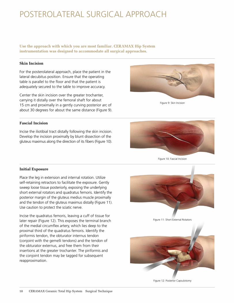
Figure 9: Skin Incision
Figure 10: Fascial Incision
Figure 11: Short External Rotators
Figure 12: Posterior Capsulotomy
Skin Incision
For the posterolateral approach, place the patient in the lateral decubitus position. Ensure that the operating table is parallel to the floor and that the patient is adequately secured to the table to improve accuracy.
Center the skin incision over the greater trochanter, carrying it distally over the femoral shaft for about 15 cm and proximally in a gently curving posterior arc of about 30 degrees for about the same distance (Figure 9).
Fascial Incision
Incise the iliotibial tract distally following the skin incision. Develop the incision proximally by blunt dissection of the gluteus maximus along the direction of its fibers (Figure 10).
Initial Exposure
Place the leg in extension and internal rotation. Utilize self-retaining retractors to facilitate the exposure. Gently sweep loose tissue posteriorly, exposing the underlying short external rotators and quadratus femoris. Identify the posterior margin of the gluteus medius muscle proximally and the tendon of the gluteus maximus distally (Figure 11). Use caution to protect the sciatic nerve.
Incise the quadratus femoris, leaving a cuff of tissue for later repair (Figure 12). This exposes the terminal branch of the medial circumflex artery, which lies deep to the proximal third of the quadratus femoris. Identify the piriformis tendon, the obturator internus tendon (conjoint with the gemelli tendons) and the tendon of the obturator externus, and free them from their insertions at the greater trochanter. The piriformis and the conjoint tendon may be tagged for subsequent reapproximation.
POSTEROLATERAL SURGICAL APPROACH
Use the approach with which you are most familiar. CERAMAX Hip System instrumentation was designed to accommodate all surgical approaches.
11 CERAMAX Ceramic Total Hip System Surgical Technique
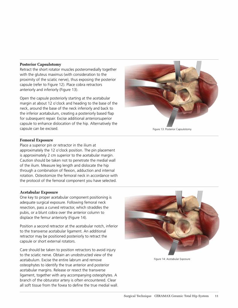
Posterior CapsulotomyRetract the short rotator muscles posteromedially together with the gluteus maximus (with consideration to the proximity of the sciatic nerve), thus exposing the posterior capsule (refer to Figure 12). Place cobra retractors anteriorly and inferiorly (Figure 13).
Open the capsule posteriorly starting at the acetabular margin at about 12 o’clock and heading to the base of the neck, around the base of the neck inferiorly and back to the inferior acetabulum, creating a posteriorly based flap for subsequent repair. Excise additional anteriorsuperior capsule to enhance dislocation of the hip. Alternatively the capsule can be excised. Figure 13: Posterior Capsulotomy
Femoral ExposurePlace a superior pin or retractor in the ilium at approximately the 12 o’clock position. The pin placement is approximately 2 cm superior to the acetabular margin. Caution should be taken not to penetrate the medial wall of the ilium. Measure leg length and dislocate the hip through a combination of flexion, adduction and internal rotation. Osteotomize the femoral neck in accordance with the protocol of the femoral component you have selected.
Acetabular ExposureOne key to proper acetabular component positioning is adequate surgical exposure. Following femoral neck resection, pass a curved retractor, which straddles the pubis, or a blunt cobra over the anterior column to displace the femur anteriorly (Figure 14).
Position a second retractor at the acetabular notch, inferior to the transverse acetabular ligament. An additional retractor may be positioned posteriorly to retract the capsule or short external rotators.
Care should be taken to position retractors to avoid injury to the sciatic nerve. Obtain an unobstructed view of the acetabulum. Excise the entire labrum and remove osteophytes to identify the true anterior and posterior acetabular margins. Release or resect the transverse ligament, together with any accompanying osteophytes. A branch of the obturator artery is often encountered. Clear all soft tissue from the fovea to define the true medial wall.
Figure 14: Acetabular Exposure
Surgical Technique CERAMAX Ceramic Total Hip System 11
ACETABULAR REAMING
Figure 15: Acetabular Reaming
Figure 16: Acetabular Reaming
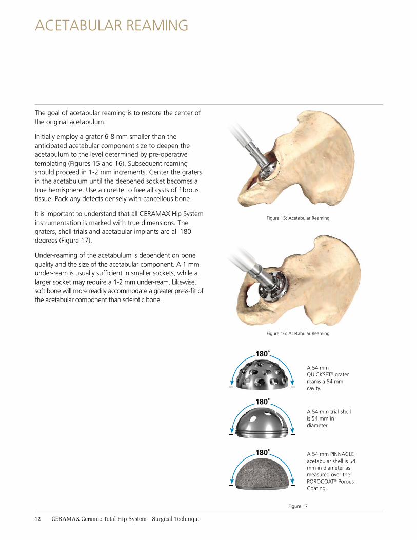
A 54 mm QUICKSET® grater reams a 54 mm cavity.
A 54 mm trial shell is 54 mm in diameter.
A 54 mm PINNACLE acetabular shell is 54 mm in diameter as measured over the POROCOAT® Porous Coating.
The goal of acetabular reaming is to restore the center of the original acetabulum.
Initially employ a grater 6-8 mm smaller than the anticipated acetabular component size to deepen the acetabulum to the level determined by pre-operative templating (Figures 15 and 16). Subsequent reaming should proceed in 1-2 mm increments. Center the graters in the acetabulum until the deepened socket becomes a true hemisphere. Use a curette to free all cysts of fibrous tissue. Pack any defects densely with cancellous bone.
It is important to understand that all CERAMAX Hip System instrumentation is marked with true dimensions. The graters, shell trials and acetabular implants are all 180 degrees (Figure 17).
Under-reaming of the acetabulum is dependent on bone quality and the size of the acetabular component. A 1 mm under-ream is usually sufficient in smaller sockets, while a larger socket may require a 1-2 mm under-ream. Likewise, soft bone will more readily accommodate a greater press-fit of the acetabular component than sclerotic bone.
180˚
180˚
180˚
Figure 17
11 CERAMAX Ceramic Total Hip System Surgical Technique
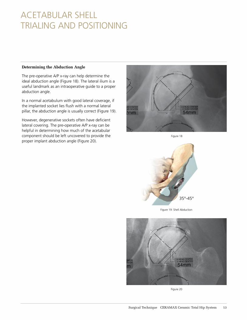
Determining the Abduction Angle
The pre-operative A/P x-ray can help determine the ideal abduction angle (Figure 18). The lateral ilium is a useful landmark as an intraoperative guide to a proper abduction angle.
In a normal acetabulum with good lateral coverage, if the implanted socket lies flush with a normal lateral pillar, the abduction angle is usually correct (Figure 19).
However, degenerative sockets often have deficient lateral covering. The pre-operative A/P x-ray can be helpful in determining how much of the acetabular component should be left uncovered to provide the proper implant abduction angle (Figure 20).
Figure 18
35°-45°
Figure 19: Shell Abduction
ACETABULAR SHELL TRIALING AND POSITIONING
Figure 20
Surgical Technique CERAMAX Ceramic Total Hip System 13
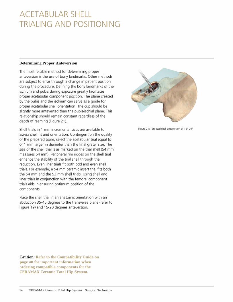
Determining Proper Anteversion
The most reliable method for determining proper anteversion is the use of bony landmarks. Other methods are subject to error through a change in patient position during the procedure. Defining the bony landmarks of the ischium and pubis during exposure greatly facilitates proper acetabular component position. The plane created by the pubis and the ischium can serve as a guide for proper acetabular shell orientation. The cup should be slightly more anteverted than the pubis/ischial plane. This relationship should remain constant regardless of the depth of reaming (Figure 21).
Shell trials in 1 mm incremental sizes are available to assess shell fit and orientation. Contingent on the quality of the prepared bone, select the acetabular trial equal to or 1 mm larger in diameter than the final grater size. The size of the shell trial is as marked on the trial shell (54 mm measures 54 mm). Peripheral rim ridges on the shell trial enhance the stability of the trial shell through trial reduction. Even liner trials fit both odd and even shell trials. For example, a 54 mm ceramic insert trial fits both the 54 mm and the 53 mm shell trials. Using shell and liner trials in conjunction with the femoral component trials aids in ensuring optimum position of the components.
Place the shell trial in an anatomic orientation with an abduction 35-45 degrees to the transverse plane (refer to Figure 19) and 15-20 degrees anteversion.
Figure 21: Targeted shell anteversion of 15°-20°
Caution: Refer to the Compatibility Guide on page 40 for important information when ordering compatible components for the CERAMAX Ceramic Total Hip System.
ACETABULAR SHELL TRIALING AND POSITIONING
11 CERAMAX Ceramic Total Hip System Surgical Technique
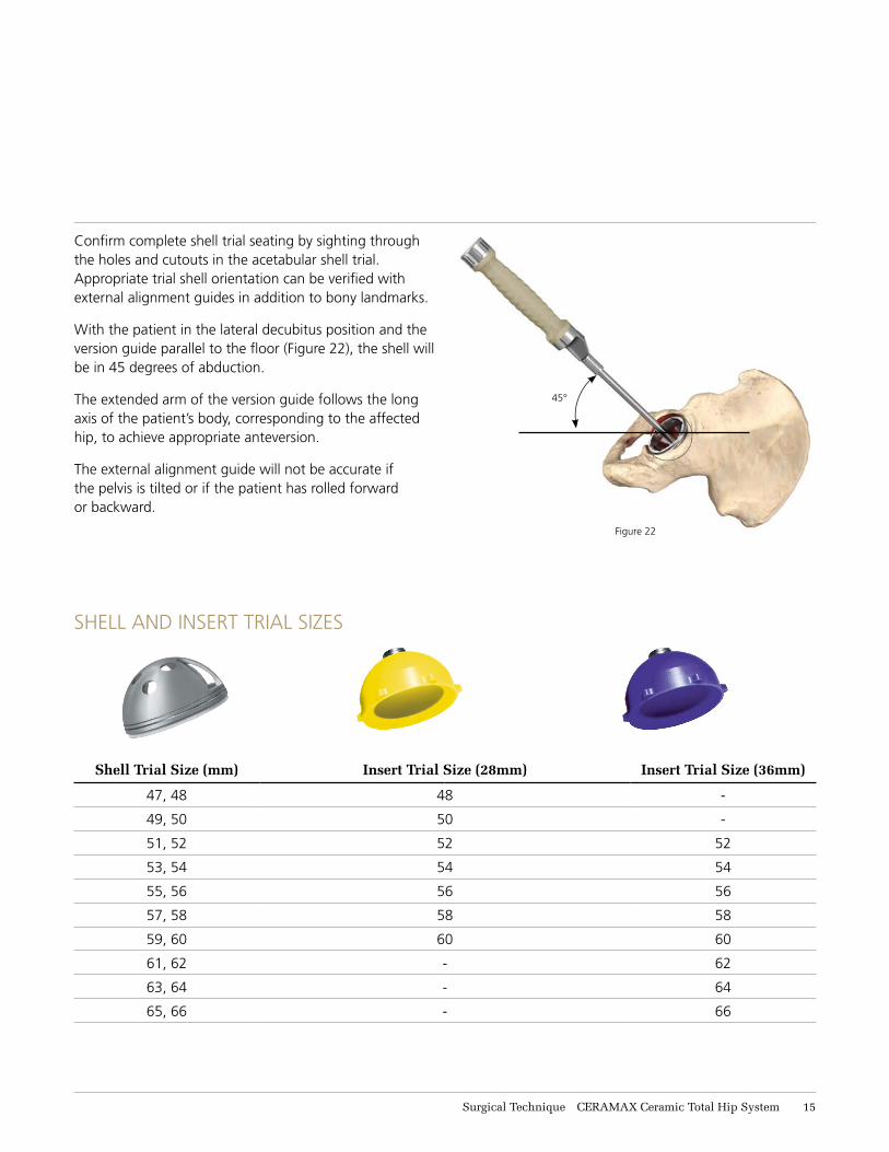
Confirm complete shell trial seating by sighting through the holes and cutouts in the acetabular shell trial. Appropriate trial shell orientation can be verified with external alignment guides in addition to bony landmarks.
With the patient in the lateral decubitus position and the version guide parallel to the floor (Figure 22), the shell will be in 45 degrees of abduction.
The extended arm of the version guide follows the long axis of the patient’s body, corresponding to the affected hip, to achieve appropriate anteversion.
The external alignment guide will not be accurate if the pelvis is tilted or if the patient has rolled forward or backward.
45°
SHELL AND INSERT TRIAL SIZES
Shell Trial Size (mm) Insert Trial Size (28mm) Insert Trial Size (36mm)
47, 48 48 -
49, 50 50 -
51, 52 52 52
53, 54 54 54
55, 56 56 56
57, 58 58 58
59, 60 60 60
61, 62 - 62
63, 64 - 64
65, 66 - 66
Figure 22
Surgical Technique CERAMAX Ceramic Total Hip System 11
IMPLANTING THE ACETABULAR SHELL
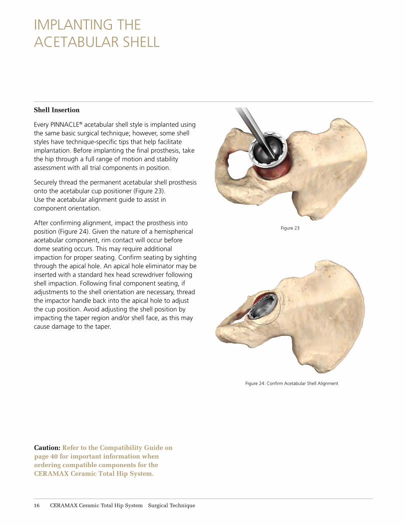
Shell Insertion
Every PINNACLE® acetabular shell style is implanted using the same basic surgical technique; however, some shell styles have technique-specific tips that help facilitate implantation. Before implanting the final prosthesis, take the hip through a full range of motion and stability assessment with all trial components in position.
Securely thread the permanent acetabular shell prosthesis onto the acetabular cup positioner (Figure 23). Use the acetabular alignment guide to assist in component orientation.
After confirming alignment, impact the prosthesis into position (Figure 24). Given the nature of a hemispherical acetabular component, rim contact will occur before dome seating occurs. This may require additional impaction for proper seating. Confirm seating by sighting through the apical hole. An apical hole eliminator may be inserted with a standard hex head screwdriver following shell impaction. Following final component seating, if adjustments to the shell orientation are necessary, thread the impactor handle back into the apical hole to adjust the cup position. Avoid adjusting the shell position by impacting the taper region and/or shell face, as this may cause damage to the taper.
Figure 23
Figure 24: Confirm Acetabular Shell Alignment
Caution: Refer to the Compatibility Guide on page 40 for important information when ordering compatible components for the CERAMAX Ceramic Total Hip System.
16 CERAMAX Ceramic Total Hip System Surgical Technique
SafeQuadrant
34°34°
Figure 27: Screw Angulation
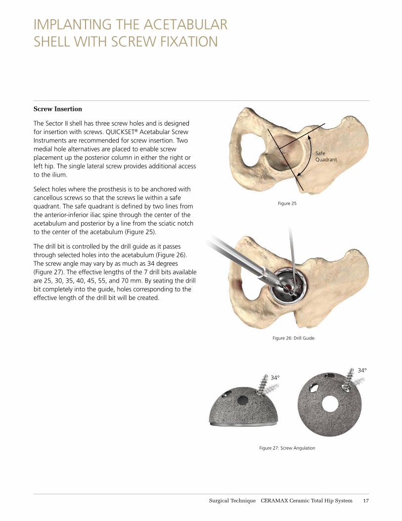
Screw Insertion
The Sector II shell has three screw holes and is designed for insertion with screws. QUICKSET® Acetabular Screw Instruments are recommended for screw insertion. Two medial hole alternatives are placed to enable screw placement up the posterior column in either the right or left hip. The single lateral screw provides additional access to the ilium.
Select holes where the prosthesis is to be anchored with cancellous screws so that the screws lie within a safe quadrant. The safe quadrant is defined by two lines from the anterior-inferior iliac spine through the center of the acetabulum and posterior by a line from the sciatic notch to the center of the acetabulum (Figure 25).
The drill bit is controlled by the drill guide as it passes through selected holes into the acetabulum (Figure 26). The screw angle may vary by as much as 34 degrees (Figure 27). The effective lengths of the 7 drill bits available are 25, 30, 35, 40, 45, 55, and 70 mm. By seating the drill bit completely into the guide, holes corresponding to the effective length of the drill bit will be created.
Figure 25
Figure 26: Drill Guide
IMPLANTING THE ACETABULAR SHELL WITH SCREW FIXATION
Surgical Technique CERAMAX Ceramic Total Hip System 17
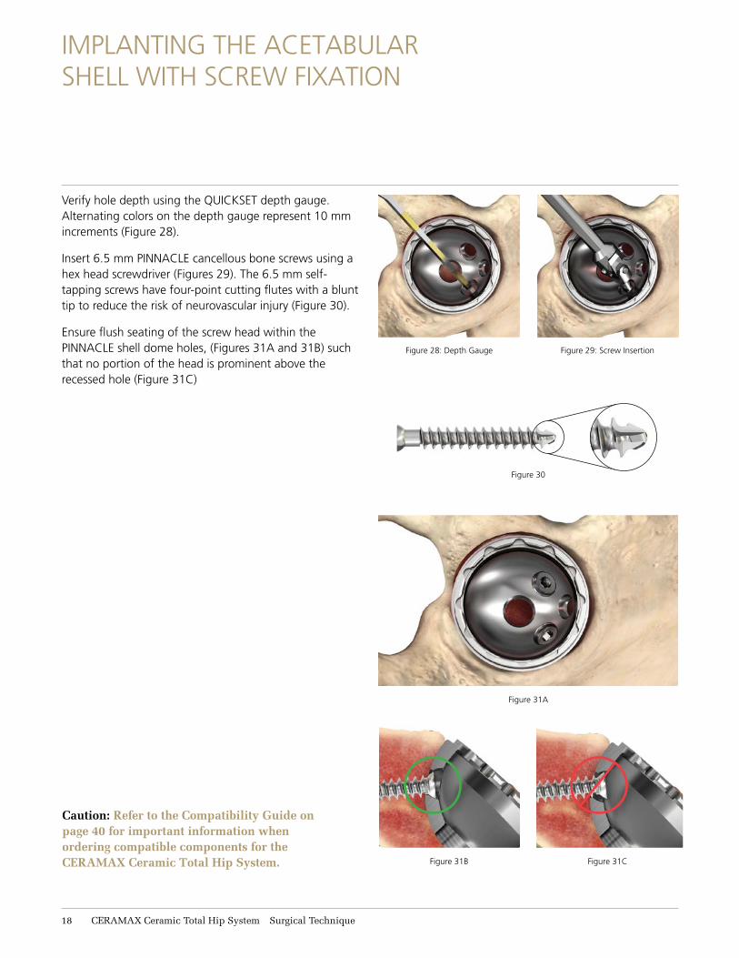
Verify hole depth using the QUICKSET depth gauge. Alternating colors on the depth gauge represent 10 mm increments (Figure 28).
Insert 6.5 mm PINNACLE cancellous bone screws using a hex head screwdriver (Figures 29). The 6.5 mm self-tapping screws have four-point cutting flutes with a blunt tip to reduce the risk of neurovascular injury (Figure 30).
Ensure flush seating of the screw head within the PINNACLE shell dome holes, (Figures 31A and 31B) such that no portion of the head is prominent above the recessed hole (Figure 31C)
Figure 28: Depth Gauge Figure 29: Screw Insertion
Figure 31A
Figure 30
Figure 31CFigure 31B
IMPLANTING THE ACETABULAR SHELL WITH SCREW FIXATION
Caution: Refer to the Compatibility Guide on page 40 for important information when ordering compatible components for the CERAMAX Ceramic Total Hip System.
18 CERAMAX Ceramic Total Hip System Surgical Technique
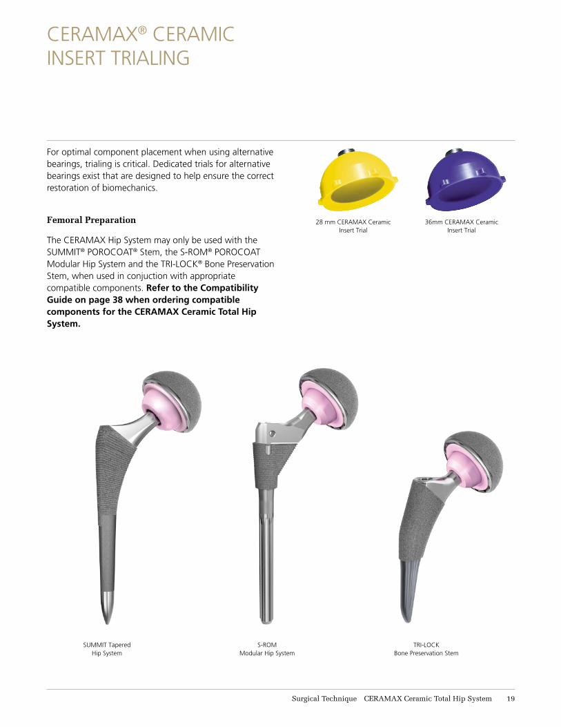
28 mm CERAMAX Ceramic Insert Trial
36mm CERAMAX Ceramic Insert Trial
S-ROM Modular Hip System
SUMMIT Tapered Hip System
TRI-LOCK Bone Preservation Stem
CERAMAX® CERAMIC INSERT TRIALING
For optimal component placement when using alternative bearings, trialing is critical. Dedicated trials for alternative bearings exist that are designed to help ensure the correct restoration of biomechanics.
Femoral Preparation
The CERAMAX Hip System may only be used with the SUMMIT® POROCOAT® Stem, the S-ROM® POROCOAT Modular Hip System and the TRI-LOCK® Bone Preservation Stem, when used in conjuction with appropriate compatible components. Refer to the Compatibility Guide on page 38 when ordering compatible components for the CERAMAX Ceramic Total Hip System.
Surgical Technique CERAMAX Ceramic Total Hip System 19
S-ROM® SURGICAL TECHNIQUE
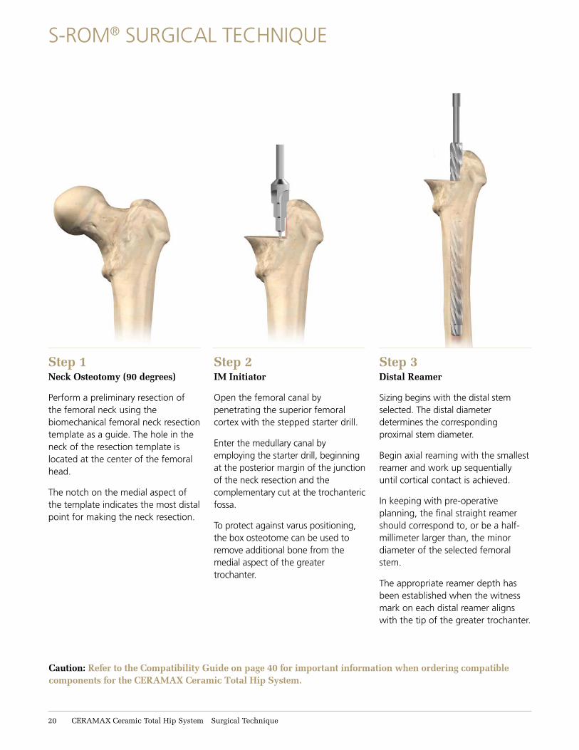
Step 2IM Initiator
Open the femoral canal by penetrating the superior femoral cortex with the stepped starter drill.
Enter the medullary canal by employing the starter drill, beginning at the posterior margin of the junction of the neck resection and the complementary cut at the trochanteric fossa.
To protect against varus positioning, the box osteotome can be used to remove additional bone from the medial aspect of the greater trochanter.
Step 1Neck Osteotomy (90 degrees)
Perform a preliminary resection of the femoral neck using the biomechanical femoral neck resection template as a guide. The hole in the neck of the resection template is located at the center of the femoral head.
The notch on the medial aspect of the template indicates the most distal point for making the neck resection.
Step 3Distal Reamer
Sizing begins with the distal stem selected. The distal diameter determines the corresponding proximal stem diameter.
Begin axial reaming with the smallest reamer and work up sequentially until cortical contact is achieved.
In keeping with pre-operative planning, the final straight reamer should correspond to, or be a half-millimeter larger than, the minor diameter of the selected femoral stem.
The appropriate reamer depth has been established when the witness mark on each distal reamer aligns with the tip of the greater trochanter.
Caution: Refer to the Compatibility Guide on page 40 for important information when ordering compatible components for the CERAMAX Ceramic Total Hip System.
11 CERAMAX Ceramic Total Hip System Surgical Technique
Surgical Technique CERAMAX Ceramic Total Hip System 11
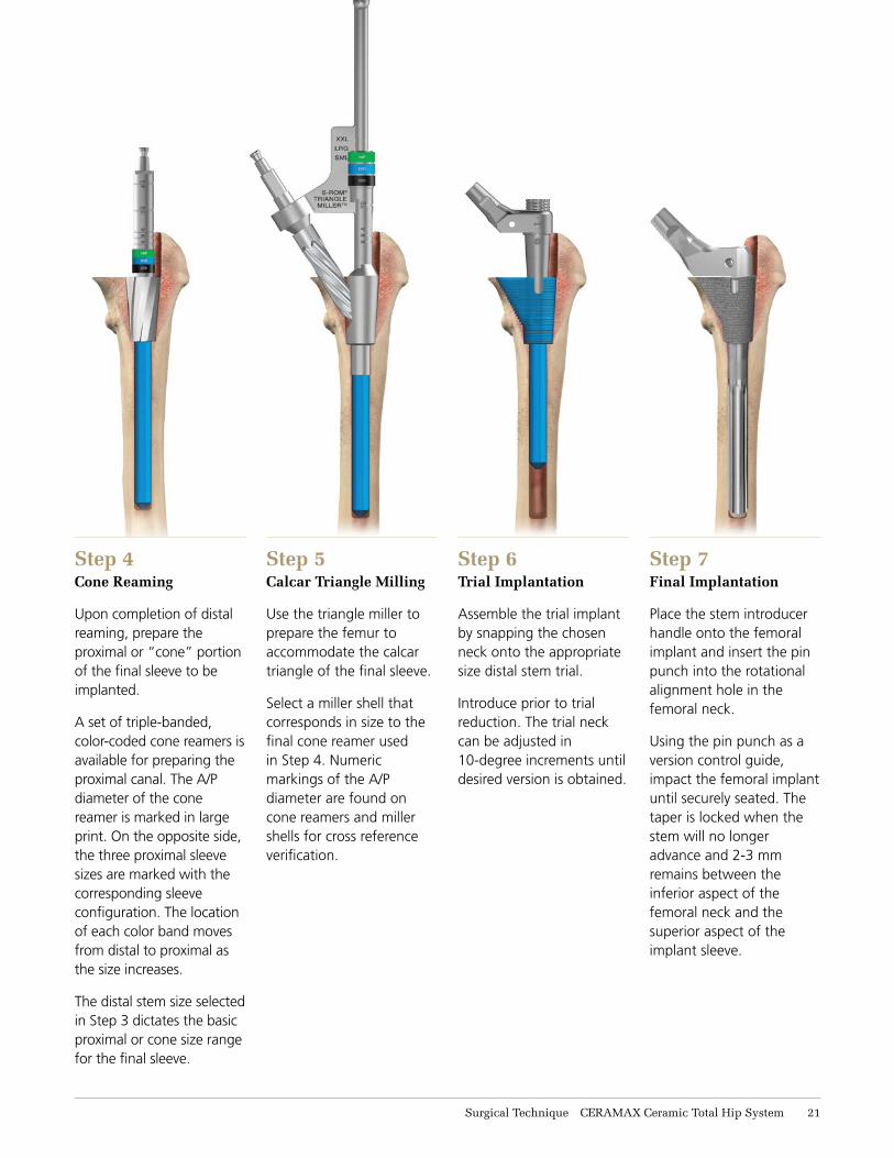
Step 5Calcar Triangle Milling
Use the triangle miller to prepare the femur to accommodate the calcar triangle of the final sleeve.
Select a miller shell that corresponds in size to the final cone reamer used in Step 4. Numeric markings of the A/P diameter are found on cone reamers and miller shells for cross reference verification.
Step 6Trial Implantation
Assemble the trial implant by snapping the chosen neck onto the appropriate size distal stem trial.
Introduce prior to trial reduction. The trial neck can be adjusted in 10-degree increments until desired version is obtained.
Step 7Final Implantation
Place the stem introducer handle onto the femoral implant and insert the pin punch into the rotational alignment hole in the femoral neck.
Using the pin punch as a version control guide, impact the femoral implant until securely seated. The taper is locked when the stem will no longer advance and 2-3 mm remains between the inferior aspect of the femoral neck and the superior aspect of the implant sleeve.
Step 4Cone Reaming
Upon completion of distal reaming, prepare the proximal or “cone” portion of the final sleeve to be implanted.
A set of triple-banded, color-coded cone reamers is available for preparing the proximal canal. The A/P diameter of the cone reamer is marked in large print. On the opposite side, the three proximal sleeve sizes are marked with the corresponding sleeve configuration. The location of each color band moves from distal to proximal as the size increases.
The distal stem size selected in Step 3 dictates the basic proximal or cone size range for the final sleeve.
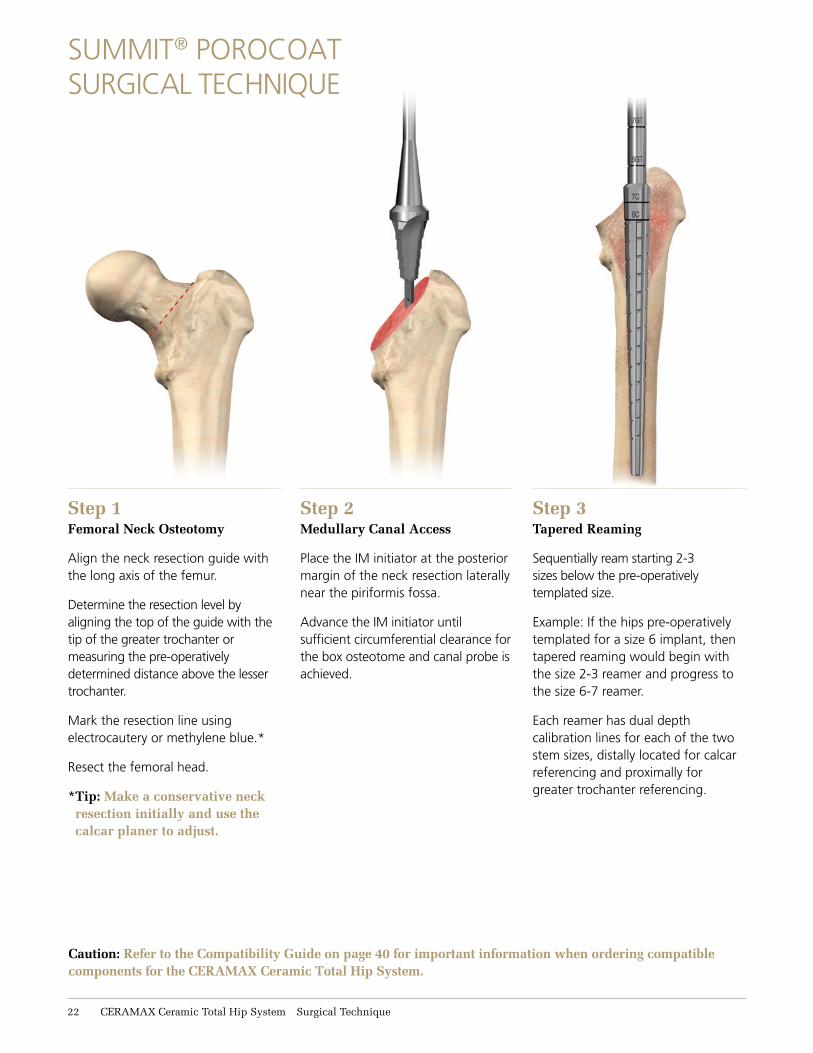
Step 1Femoral Neck Osteotomy
Align the neck resection guide with the long axis of the femur.
Determine the resection level by aligning the top of the guide with the tip of the greater trochanter or measuring the pre-operatively determined distance above the lesser trochanter.
Mark the resection line using electrocautery or methylene blue.*
Resect the femoral head.
* Tip: Make a conservative neck resection initially and use the calcar planer to adjust.
Step 2Medullary Canal Access
Place the IM initiator at the posterior margin of the neck resection laterally near the piriformis fossa.
Advance the IM initiator until sufficient circumferential clearance for the box osteotome and canal probe is achieved.
SUMMIT® POROCOAT SURGICAL TECHNIQUE
Step 3Tapered Reaming
Sequentially ream starting 2-3 sizes below the pre-operatively templated size.
Example: If the hips pre-operatively templated for a size 6 implant, then tapered reaming would begin with the size 2-3 reamer and progress to the size 6-7 reamer.
Each reamer has dual depth calibration lines for each of the two stem sizes, distally located for calcar referencing and proximally for greater trochanter referencing.
Caution: Refer to the Compatibility Guide on page 40 for important information when ordering compatible components for the CERAMAX Ceramic Total Hip System.
11 CERAMAX Ceramic Total Hip System Surgical Technique
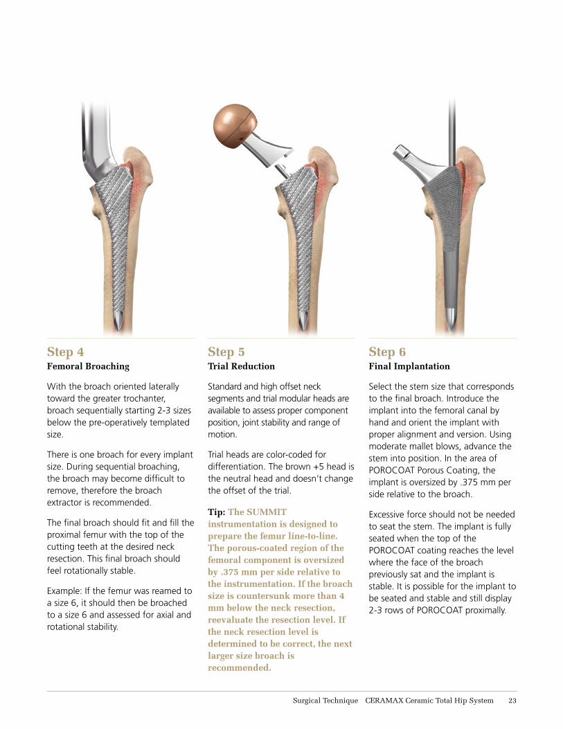
Step 4Femoral Broaching
With the broach oriented laterally toward the greater trochanter, broach sequentially starting 2-3 sizes below the pre-operatively templated size.
There is one broach for every implant size. During sequential broaching, the broach may become difficult to remove, therefore the broach extractor is recommended.
The final broach should fit and fill the proximal femur with the top of the cutting teeth at the desired neck resection. This final broach should feel rotationally stable.
Example: If the femur was reamed to a size 6, it should then be broached to a size 6 and assessed for axial and rotational stability.
Step 5Trial Reduction
Standard and high offset neck segments and trial modular heads are available to assess proper component position, joint stability and range of motion.
Trial heads are color-coded for differentiation. The brown +5 head is the neutral head and doesn’t change the offset of the trial.
Step 6Final Implantation
Select the stem size that corresponds to the final broach. Introduce the implant into the femoral canal by hand and orient the implant with proper alignment and version. Using moderate mallet blows, advance the stem into position. In the area of POROCOAT Porous Coating, the implant is oversized by .375 mm per side relative to the broach.
Excessive force should not be needed to seat the stem. The implant is fully seated when the top of the POROCOAT coating reaches the level where the face of the broach previously sat and the implant is stable. It is possible for the implant to be seated and stable and still display 2-3 rows of POROCOAT proximally.
Tip: The SUMMIT instrumentation is designed to prepare the femur line-to-line. The porous-coated region of the femoral component is oversized by .375 mm per side relative to the instrumentation. If the broach size is countersunk more than 4 mm below the neck resection, reevaluate the resection level. If the neck resection level is determined to be correct, the next larger size broach is recommended.
Surgical Technique CERAMAX Ceramic Total Hip System 13
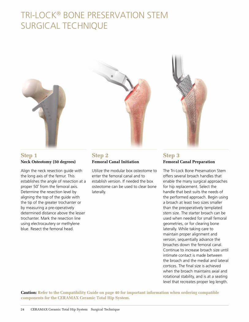
TRI-LOCK® BONE PRESERVATION STEM SURGICAL TECHNIQUE
Step 2Femoral Canal Initiation
Utilize the modular box osteotome to enter the femoral canal and to establish version. If needed the box osteotome can be used to clear bone laterally.
Step 1Neck Osteotomy (50 degrees)
Align the neck resection guide with the long axis of the femur. This establishes the angle of resection at a proper 50˚ from the femoral axis. Determine the resection level by aligning the top of the guide with the tip of the greater trochanter or by measuring a pre-operatively determined distance above the lesser trochanter. Mark the resection line using electrocautery or methylene blue. Resect the femoral head.
Step 3Femoral Canal Preparation
The Tri-Lock Bone Preservation Stem offers several broach handles that enable the many surgical approaches for hip replacement. Select the handle that best suits the needs of the performed approach. Begin using a broach at least two sizes smaller than the preoperatively templated stem size. The starter broach can be used when needed for small femoral geometries, or for clearing bone laterally. While taking care to maintain proper alignment and version, sequentially advance the broaches down the femoral canal. Continue to increase broach size until intimate contact is made between the broach and the medial and lateral cortices. The final size is achieved when the broach maintains axial and rotational stability, and is at a seating level that recreates proper leg length.
Caution: Refer to the Compatibility Guide on page 40 for important information when ordering compatible components for the CERAMAX Ceramic Total Hip System.
11 CERAMAX Ceramic Total Hip System Surgical Technique
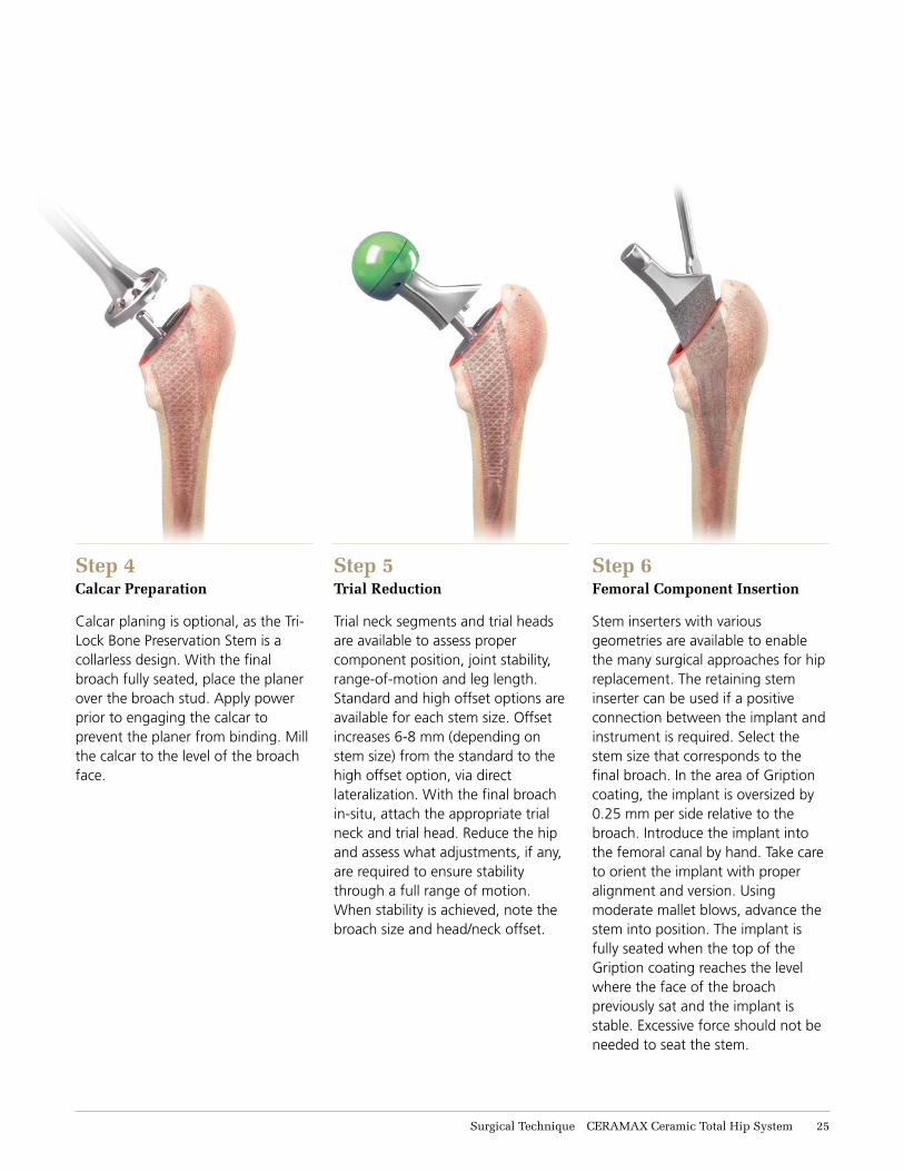
Step 5Trial Reduction
Trial neck segments and trial heads are available to assess proper component position, joint stability, range-of-motion and leg length. Standard and high offset options are available for each stem size. Offset increases 6-8 mm (depending on stem size) from the standard to the high offset option, via direct lateralization. With the final broach in-situ, attach the appropriate trial neck and trial head. Reduce the hip and assess what adjustments, if any, are required to ensure stability through a full range of motion. When stability is achieved, note the broach size and head/neck offset.
Step 6Femoral Component Insertion
Stem inserters with various geometries are available to enable the many surgical approaches for hip replacement. The retaining stem inserter can be used if a positive connection between the implant and instrument is required. Select the stem size that corresponds to the final broach. In the area of Gription coating, the implant is oversized by 0.25 mm per side relative to the broach. Introduce the implant into the femoral canal by hand. Take care to orient the implant with proper alignment and version. Using moderate mallet blows, advance the stem into position. The implant is fully seated when the top of the Gription coating reaches the level where the face of the broach previously sat and the implant is stable. Excessive force should not be needed to seat the stem.
Step 4Calcar Preparation
Calcar planing is optional, as the Tri-Lock Bone Preservation Stem is a collarless design. With the final broach fully seated, place the planer over the broach stud. Apply power prior to engaging the calcar to prevent the planer from binding. Mill the calcar to the level of the broach face.
Surgical Technique CERAMAX Ceramic Total Hip System 11
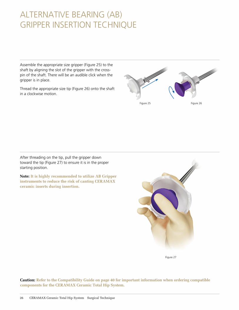
Assemble the appropriate size gripper (Figure 25) to the shaft by aligning the slot of the gripper with the cross-pin of the shaft. There will be an audible click when the gripper is in place.
Thread the appropriate size tip (Figure 26) onto the shaft in a clockwise motion.
ALTERNATIVE BEARING (AB) GRIPPER INSERTION TECHNIQUE
Figure 27
Figure 26Figure 25
After threading on the tip, pull the gripper down toward the tip (Figure 27) to ensure it is in the proper starting position.
Note: It is highly recommended to utilize AB Gripper instruments to reduce the risk of canting CERAMAX ceramic inserts during insertion.
Caution: Refer to the Compatibility Guide on page 40 for important information when ordering compatible components for the CERAMAX Ceramic Total Hip System.
16 CERAMAX Ceramic Total Hip System Surgical Technique
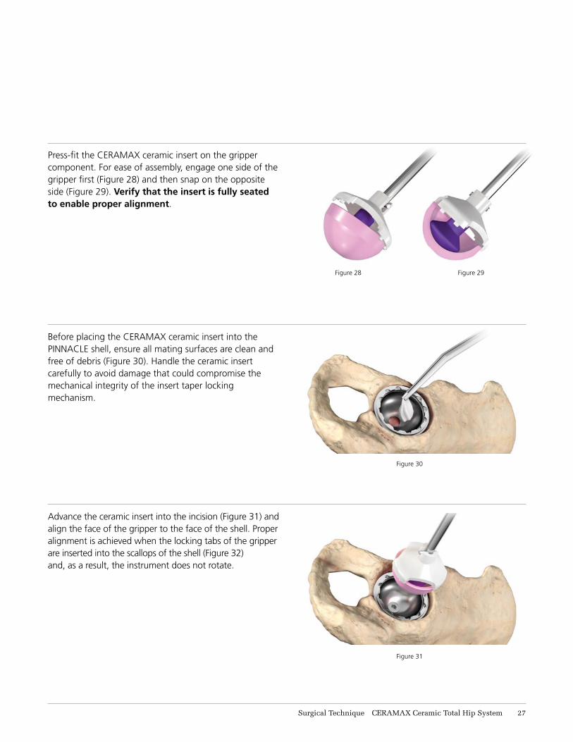
Figure 28 Figure 29
Press-fit the CERAMAX ceramic insert on the gripper component. For ease of assembly, engage one side of the gripper first (Figure 28) and then snap on the opposite side (Figure 29). Verify that the insert is fully seated to enable proper alignment.
Figure 30
Before placing the CERAMAX ceramic insert into the PINNACLE shell, ensure all mating surfaces are clean and free of debris (Figure 30). Handle the ceramic insert carefully to avoid damage that could compromise the mechanical integrity of the insert taper locking mechanism.
Figure 31
Advance the ceramic insert into the incision (Figure 31) and align the face of the gripper to the face of the shell. Proper alignment is achieved when the locking tabs of the gripper are inserted into the scallops of the shell (Figure 32) and, as a result, the instrument does not rotate.
Surgical Technique CERAMAX Ceramic Total Hip System 17
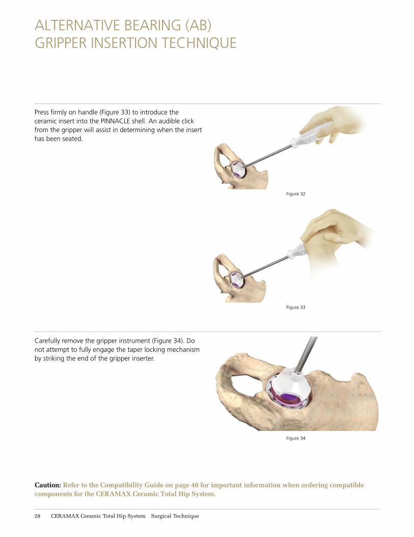
Figure 34
Carefully remove the gripper instrument (Figure 34). Do not attempt to fully engage the taper locking mechanism by striking the end of the gripper inserter.
Figure 32
Figure 33
Press firmly on handle (Figure 33) to introduce the ceramic insert into the PINNACLE shell. An audible click from the gripper will assist in determining when the insert has been seated.
ALTERNATIVE BEARING (AB) GRIPPER INSERTION TECHNIQUE
Caution: Refer to the Compatibility Guide on page 40 for important information when ordering compatible components for the CERAMAX Ceramic Total Hip System.
18 CERAMAX Ceramic Total Hip System Surgical Technique
Note: As stated under Warnings in the physician labeling, “Implants are for single use only. Do not reuse an implant in order to be sure there has been no damage to the implants.”
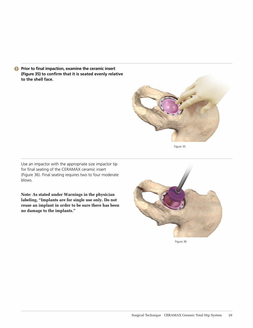
Prior to final impaction, examine the ceramic insert (Figure 35) to confirm that it is seated evenly relative to the shell face.
Figure 35
Use an impactor with the appropriate size impactor tip for final seating of the CERAMAX ceramic insert (Figure 36). Final seating requires two to four moderate blows.
Figure 36
!
Surgical Technique CERAMAX Ceramic Total Hip System 19
SUCTION CUP INSERTION TECHNIQUE
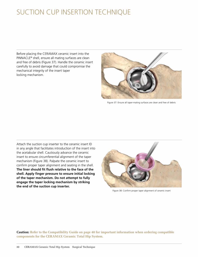
Before placing the CERAMAX ceramic insert into the PINNACLE® shell, ensure all mating surfaces are clean and free of debris (Figure 37). Handle the ceramic insert carefully to avoid damage that could compromise the mechanical integrity of the insert taper locking mechanism.
Figure 37: Ensure all taper-mating surfaces are clean and free of debris
Attach the suction cup inserter to the ceramic insert ID in any angle that facilitates introduction of the insert into the acetabular shell. Cautiously advance the ceramic insert to ensure circumferential alignment of the taper mechanism (Figure 38). Palpate the ceramic insert to confirm proper taper alignment and seating in the shell. The liner should fit flush relative to the face of the shell. Apply finger pressure to ensure initial locking of the taper mechanism. Do not attempt to fully engage the taper locking mechanism by striking the end of the suction cup inserter.
Figure 38: Confirm proper taper alignment of ceramic insert
Caution: Refer to the Compatibility Guide on page 40 for important information when ordering compatible components for the CERAMAX Ceramic Total Hip System.
31 CERAMAX Ceramic Total Hip System Surgical Technique
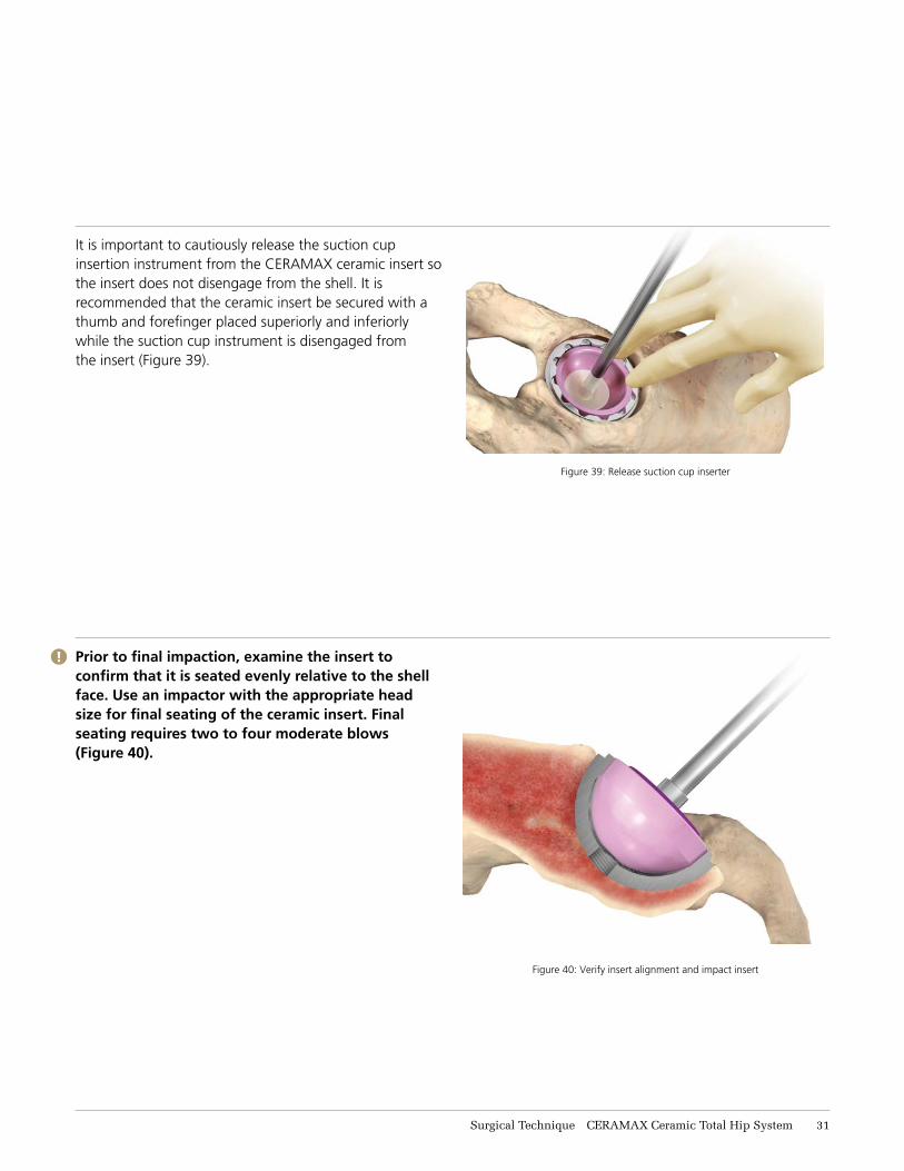
Figure 39: Release suction cup inserter
It is important to cautiously release the suction cup insertion instrument from the CERAMAX ceramic insert so the insert does not disengage from the shell. It is recommended that the ceramic insert be secured with a thumb and forefinger placed superiorly and inferiorly while the suction cup instrument is disengaged from the insert (Figure 39).
Figure 40: Verify insert alignment and impact insert
Prior to final impaction, examine the insert to confirm that it is seated evenly relative to the shell face. Use an impactor with the appropriate head size for final seating of the ceramic insert. Final seating requires two to four moderate blows (Figure 40).
!
Surgical Technique CERAMAX Ceramic Total Hip System 31
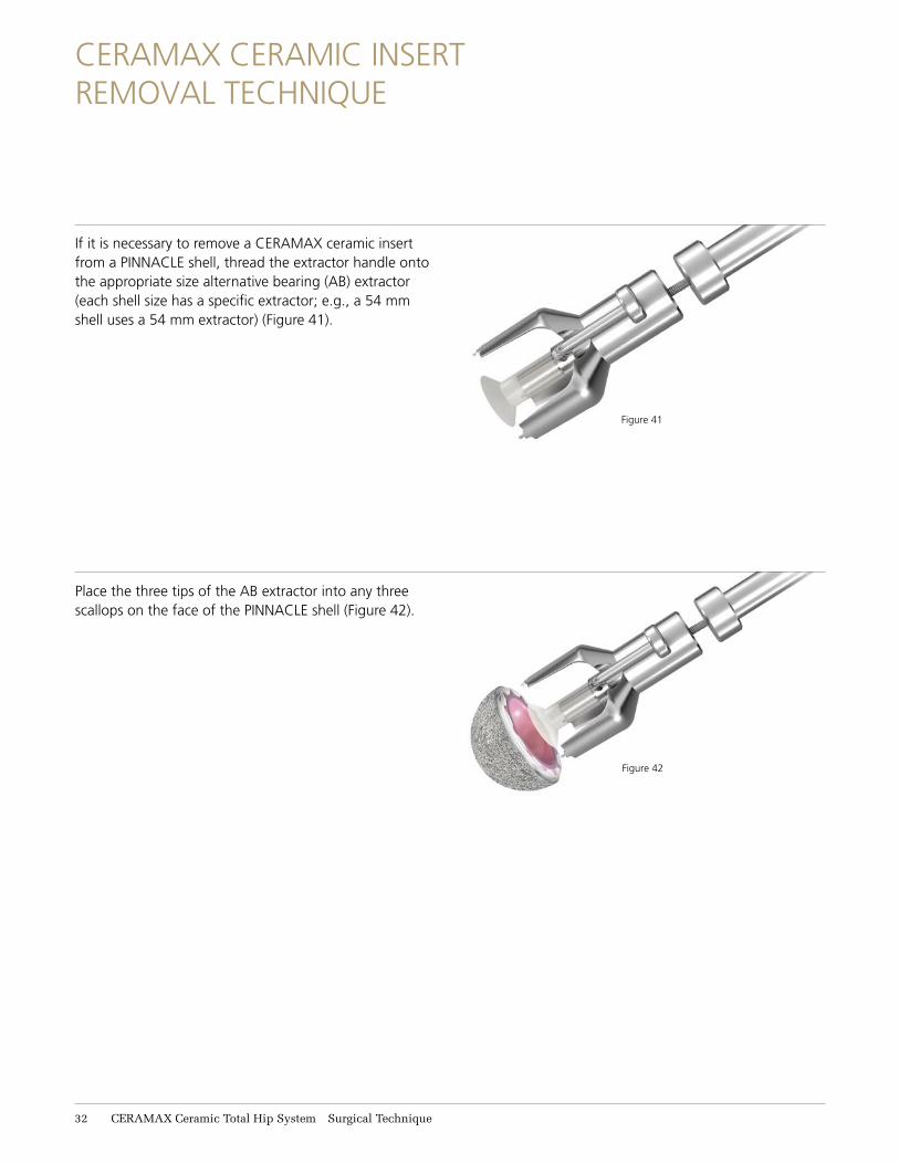
Figure 41
CERAMAX CERAMIC INSERT REMOVAL TECHNIQUE
If it is necessary to remove a CERAMAX ceramic insert from a PINNACLE shell, thread the extractor handle onto the appropriate size alternative bearing (AB) extractor (each shell size has a specific extractor; e.g., a 54 mm shell uses a 54 mm extractor) (Figure 41).
Place the three tips of the AB extractor into any three scallops on the face of the PINNACLE shell (Figure 42).
Figure 42
31 CERAMAX Ceramic Total Hip System Surgical Technique
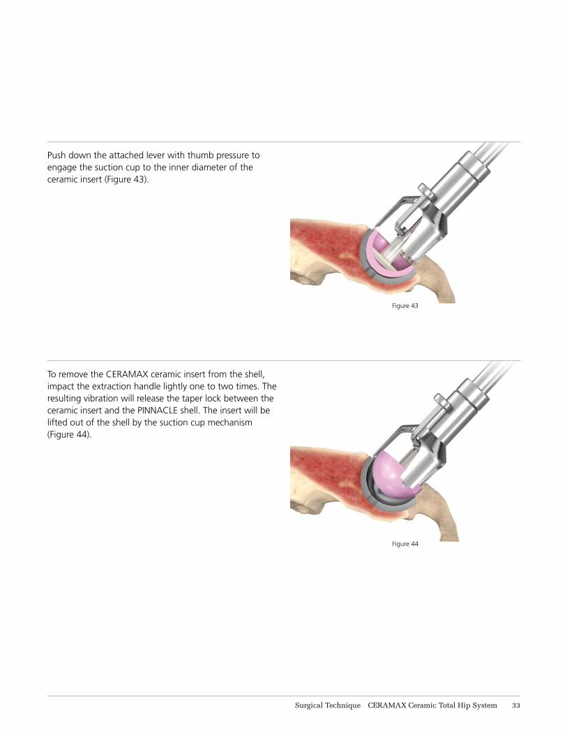
Figure 44
Push down the attached lever with thumb pressure to engage the suction cup to the inner diameter of the ceramic insert (Figure 43).
To remove the CERAMAX ceramic insert from the shell, impact the extraction handle lightly one to two times. The resulting vibration will release the taper lock between the ceramic insert and the PINNACLE shell. The insert will be lifted out of the shell by the suction cup mechanism (Figure 44).
Figure 43
Surgical Technique CERAMAX Ceramic Total Hip System 33
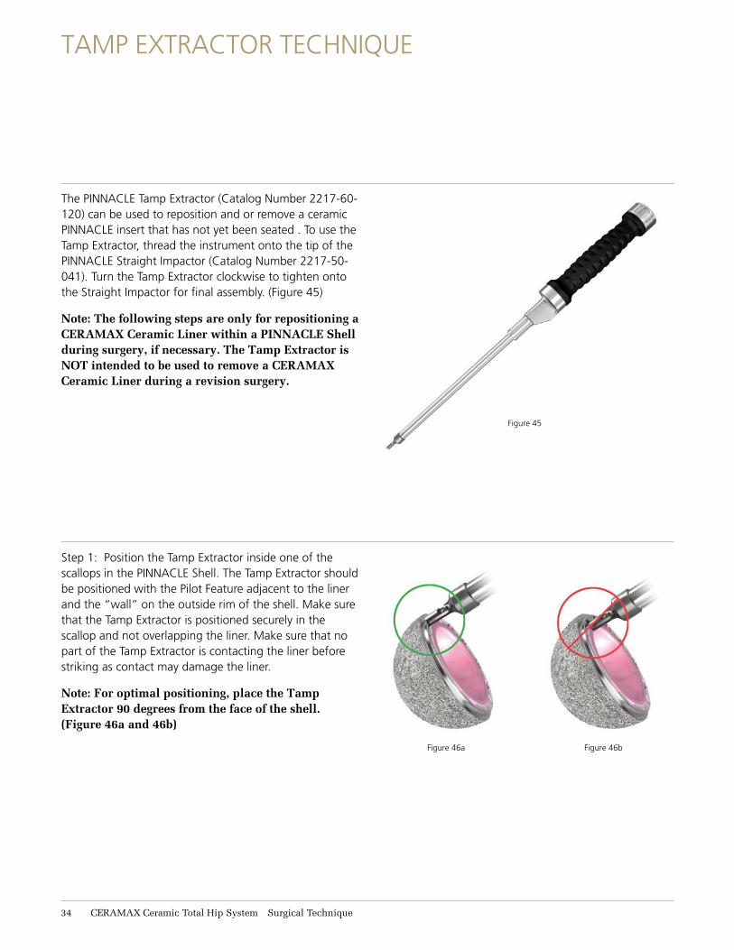
Figure 46a Figure 46b
TAMP EXTRACTOR TECHNIQUE
The PINNACLE Tamp Extractor (Catalog Number 2217-60-120) can be used to reposition and or remove a ceramic PINNACLE insert that has not yet been seated . To use the Tamp Extractor, thread the instrument onto the tip of the PINNACLE Straight Impactor (Catalog Number 2217-50-041). Turn the Tamp Extractor clockwise to tighten onto the Straight Impactor for final assembly. (Figure 45)
Note: The following steps are only for repositioning a CERAMAX Ceramic Liner within a PINNACLE Shell during surgery, if necessary. The Tamp Extractor is NOT intended to be used to remove a CERAMAX Ceramic Liner during a revision surgery.
Step 1: Position the Tamp Extractor inside one of the scallops in the PINNACLE Shell. The Tamp Extractor should be positioned with the Pilot Feature adjacent to the liner and the “wall” on the outside rim of the shell. Make sure that the Tamp Extractor is positioned securely in the scallop and not overlapping the liner. Make sure that no part of the Tamp Extractor is contacting the liner before striking as contact may damage the liner.
Note: For optimal positioning, place the Tamp Extractor 90 degrees from the face of the shell. (Figure 46a and 46b)
Figure 45
31 CERAMAX Ceramic Total Hip System Surgical Technique
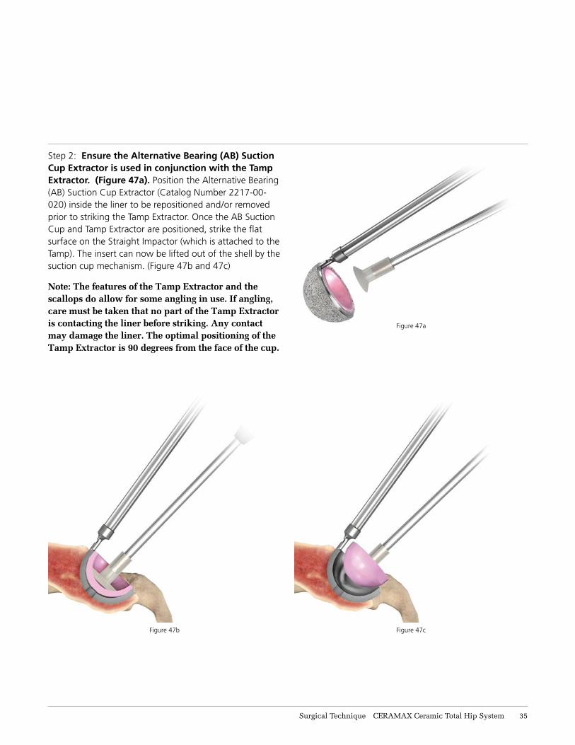
Step 2: Ensure the Alternative Bearing (AB) Suction Cup Extractor is used in conjunction with the Tamp Extractor. (Figure 47a). Position the Alternative Bearing (AB) Suction Cup Extractor (Catalog Number 2217-00-020) inside the liner to be repositioned and/or removed prior to striking the Tamp Extractor. Once the AB Suction Cup and Tamp Extractor are positioned, strike the flat surface on the Straight Impactor (which is attached to the Tamp). The insert can now be lifted out of the shell by the suction cup mechanism. (Figure 47b and 47c)
Note: The features of the Tamp Extractor and the scallops do allow for some angling in use. If angling, care must be taken that no part of the Tamp Extractor is contacting the liner before striking. Any contact may damage the liner. The optimal positioning of the Tamp Extractor is 90 degrees from the face of the cup.
Figure 47a
Figure 47b Figure 47c
Surgical Technique CERAMAX Ceramic Total Hip System 31
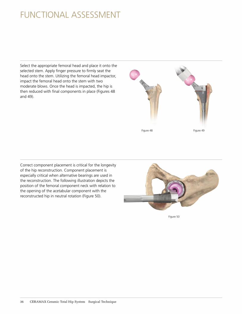
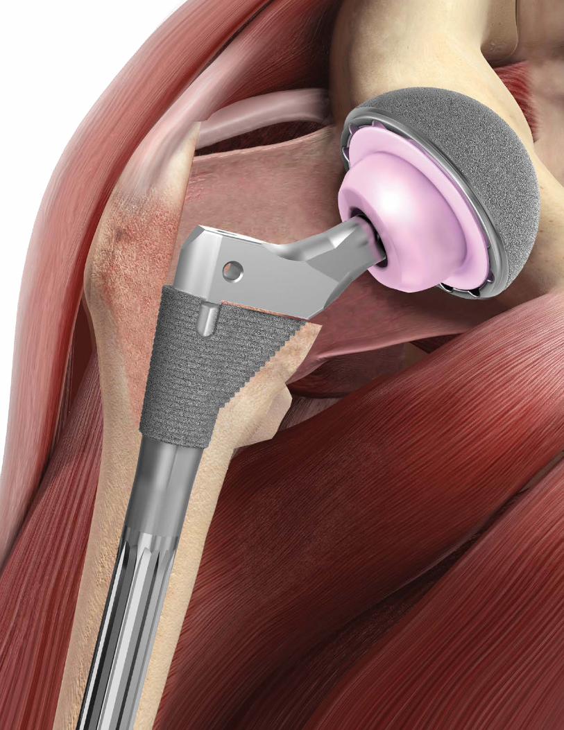
Correct component placement is critical for the longevity of the hip reconstruction. Component placement is especially critical when alternative bearings are used in the reconstruction. The following illustration depicts the position of the femoral component neck with relation to the opening of the acetabular component with the reconstructed hip in neutral rotation (Figure 50).
Figure 48 Figure 49
Figure 50
Select the appropriate femoral head and place it onto the selected stem. Apply finger pressure to firmly seat the head onto the stem. Utilizing the femoral head impactor, impact the femoral head onto the stem with two moderate blows. Once the head is impacted, the hip is then reduced with final components in place (Figures 48 and 49).
FUNCTIONAL ASSESSMENT
36 CERAMAX Ceramic Total Hip System Surgical Technique
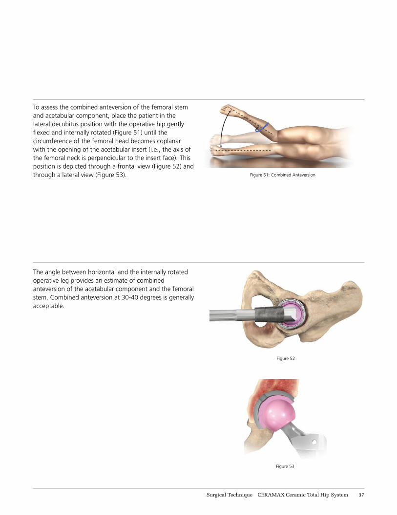
To assess the combined anteversion of the femoral stem and acetabular component, place the patient in the lateral decubitus position with the operative hip gently flexed and internally rotated (Figure 51) until the circumference of the femoral head becomes coplanar with the opening of the acetabular insert (i.e., the axis of the femoral neck is perpendicular to the insert face). This position is depicted through a frontal view (Figure 52) and through a lateral view (Figure 53).
The angle between horizontal and the internally rotated operative leg provides an estimate of combined anteversion of the acetabular component and the femoral stem. Combined anteversion at 30-40 degrees is generally acceptable.
Figure 51: Combined Anteversion
Figure 52
Figure 53
Surgical Technique CERAMAX Ceramic Total Hip System 37
TIGHT EXPOSURE AND STABILITY TIPS
TIGHT EXPOSURE
If the exposure is tight, completely incise the anterior capsule, perform a partial or complete release of the gluteus maximus tendon and release the reflected head of the rectus femoris.
Prosthetic Impingement
PROBLEM
�• Femoral implant neck levers on the component rim.
SOLUTION
• Reposition shell to correct version/abduction.• Increase head size and evaluate.• Increase anteversion of the stem.
Soft Tissue Laxity
PROBLEM
• Lax soft tissue leading to multidirectional instability.
SOLUTION
• Increase the neck length.• Advance the trochanter.
Bony Impingement
PROBLEM
• Prosthetic neck levers on anterior acetabular osteophyte.
• Greater trochanter impinging on ilium.
SOLUTION
• Remove anterior osteophytes from the acetabulum.� Increase stem offset to move trochanter away from
the ilium.• Remove anterior trochanteric bone.
Soft Tissue Impingement
PROBLEM
• Redundant anterior capsule causes head to lever out of socket.
SOLUTION
• Resect redundant anterior capsule.
STABILITY ASSESSMENTPosterior Instability
With the trial implants in place, place the hip in 90 degrees of flexion, neutral abduction and internally rotate until subluxation. If there is less than 60 degrees of internal rotation, determine the cause of instability.
38 CERAMAX Ceramic Total Hip System Surgical Technique
STABILITY ASSESSMENTAnterior Instability
With the implant trial in place, place the hip in extension and maximally externally rotate; subluxation should not occur. If subluxation occurs, assess the following:
CLOSURE
Closure is based on the surgeon’s preference and the individual case. If the capsule is retained, it is closed separately. The gluteus minimus and gluteus medius can be closed separately or as a single unit. At least one stitch is passed through bone. Tension is relieved during the repair with slight internal rotation. The repair should be tested throughout the hip range of motion.
THE KEYS TO MANAGING STABILITY ARE:1. Ensure the appropriate anteversion/abduction of the
acetabular and femoral components.
2. Restore correct leg length and femoral offset.
3. Repair the posterior capsule and rotators.
4. Work with the patient to ensure appropriate
post-operative precautions are followed.
Prosthetic Impingement
PROBLEM
• Prosthetic neck impinges on the acetabular cup.
SOLUTION
• Reposition acetabular component to decrease anteversion.
• Decrease anteversion of the femoral stem.• Increase the head size and re-evaluate.
Bony Impingement
PROBLEM
• Femur impinges on the ischium.
SOLUTION
• Increase femoral offset.• Decrease acetabular or stem anteversion.
Surgical Technique CERAMAX Ceramic Total Hip System 39
COMPATIBILITY GUIDE
36mm CERAMAX Compatible Components
Femoral Stem Options
36mm BIOLOX delta Femoral Head Off-Set Options
36mm CERAMAX Ceramic
Insert OptionsPINNACLE
Acetabular Shell Options
S-ROM Modular Hip+0, +3, +6
(11/13 Taper)52, 54, 56, 58, 60, 62, 64, 66
POROCOAT 100 Series (52 - 66mm)POROCOAT Sector II Series (52 - 66mm)
POROCOAT 300 Series (52 - 66mm)POROCOAT Multi-Hole Series (52 - 66mm)
SUMMIT POROCOAT Hip
+1.5, +5, +8.5, +12 (12/14 Taper)
52, 54, 56, 58, 60, 62, 64, 66
POROCOAT 100 Series (52 - 66mm)POROCOAT Sector II Series (52 - 66mm)
POROCOAT 300 Series (52 - 66mm) POROCOAT Multi-Hole Series (52 - 66mm)
TRI-LOCK Bone Preservation Stem
+1.5, +5, +8.5, +12 (12/14 Taper)
52, 54, 56, 58, 60, 62, 64, 66
POROCOAT 100 Series (52 - 66mm)POROCOAT Sector II Series (52 - 66mm)
POROCOAT 300 Series (52 - 66mm) POROCOAT Multi-Hole Series (52 - 66mm)
28mm CERAMAX Compatible Components
Femoral Stem Options
28mm BIOLOX delta Femoral Head Off-Set Options
28mm CERAMAX
Ceramic Insert Options
PINNACLE Acetabular Shell Options
S-ROM Modular Hip+0, +3, +6
(11/13 Taper)48, 50, 52, 54,
56, 58, 60
POROCOAT 100 Series (48 - 60mm)POROCOAT 300 Series (48 - 60mm)
POROCOAT Sector II Series (48 - 60mm)POROCOAT Multi-Hole Series (48 - 60mm)
SUMMIT POROCOAT Hip
+1.5, +5, +8.5 (12/14 Taper)
48, 50, 52, 54, 56, 58, 60
POROCOAT 100 Series (48 - 60mm)POROCOAT 300 Series (48 - 60mm)
POROCOAT Sector II Series (48 - 60mm)POROCOAT Multi-Hole Series (48 - 60mm)
TRI-LOCK Bone Preservation Stem
+1.5, +5, +8.5 (12/14 Taper)
48, 50, 52, 54, 56, 58, 60
POROCOAT 100 Series (48 - 60mm)POROCOAT 300 Series (48 - 60mm)
POROCOAT Sector II Series (48 - 60mm)POROCOAT Multi-Hole Series (48 - 60mm)
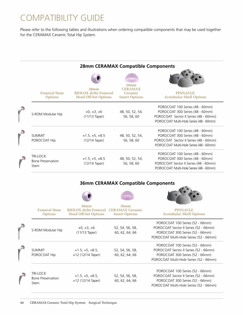
Please refer to the following tables and illustrations when ordering compatible components that may be used together for the CERAMAX Ceramic Total Hip System.
11 CERAMAX Ceramic Total Hip System Surgical Technique
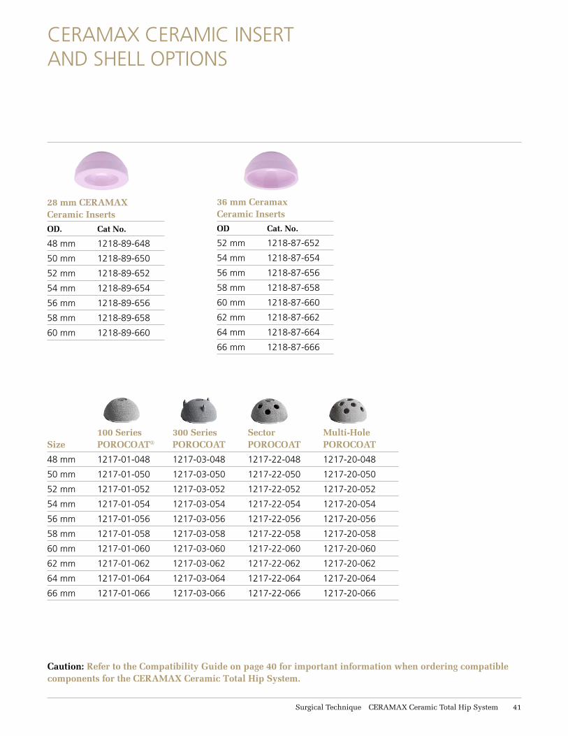
CERAMAX CERAMIC INSERT AND SHELL OPTIONS
Caution: Refer to the Compatibility Guide on page 40 for important information when ordering compatible components for the CERAMAX Ceramic Total Hip System.
36 mm CeramaxCeramic Inserts
OD Cat. No.
52 mm 1218-87-652
54 mm 1218-87-654
56 mm 1218-87-656
58 mm 1218-87-658
60 mm 1218-87-660
62 mm 1218-87-662
64 mm 1218-87-664
66 mm 1218-87-666
28 mm CERAMAX Ceramic Inserts
OD. Cat No.
48 mm 1218-89-648
50 mm 1218-89-650
52 mm 1218-89-652
54 mm 1218-89-654
56 mm 1218-89-656
58 mm 1218-89-658
60 mm 1218-89-660
Size 100 SeriesPOROCOAT®
300 SeriesPOROCOAT
Sector POROCOAT
Multi-Hole POROCOAT
48 mm 1217-01-048 1217-03-048 1217-22-048 1217-20-048
50 mm 1217-01-050 1217-03-050 1217-22-050 1217-20-050
52 mm 1217-01-052 1217-03-052 1217-22-052 1217-20-052
54 mm 1217-01-054 1217-03-054 1217-22-054 1217-20-054
56 mm 1217-01-056 1217-03-056 1217-22-056 1217-20-056
58 mm 1217-01-058 1217-03-058 1217-22-058 1217-20-058
60 mm 1217-01-060 1217-03-060 1217-22-060 1217-20-060
62 mm 1217-01-062 1217-03-062 1217-22-062 1217-20-062
64 mm 1217-01-064 1217-03-064 1217-22-064 1217-20-064
66 mm 1217-01-066 1217-03-066 1217-22-066 1217-20-066
Surgical Technique CERAMAX Ceramic Total Hip System 11
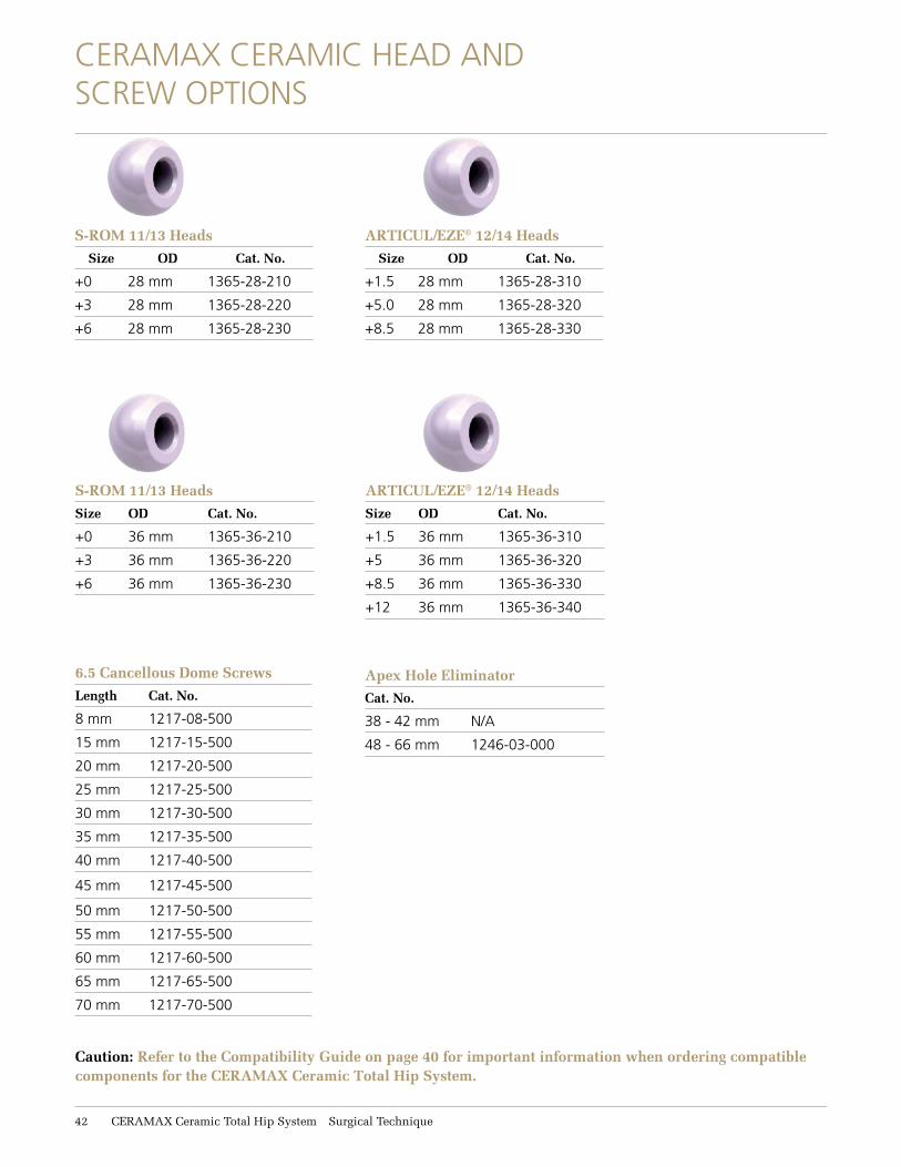
CERAMAX CERAMIC HEAD AND SCREW OPTIONS
S-ROM 11/13 Heads
Size OD Cat. No.
+0 36 mm 1365-36-210
+3 36 mm 1365-36-220
+6 36 mm 1365-36-230
ARTICUL/EZE® 12/14 Heads
Size OD Cat. No.
+1.5 36 mm 1365-36-310
+5 36 mm 1365-36-320
+8.5 36 mm 1365-36-330
+12 36 mm 1365-36-340
Apex Hole Eliminator
Cat. No.
38 - 42 mm N/A
48 - 66 mm 1246-03-000
6.5 Cancellous Dome Screws
Length Cat. No.
8 mm 1217-08-500
15 mm 1217-15-500
20 mm 1217-20-500
25 mm 1217-25-500
30 mm 1217-30-500
35 mm 1217-35-500
40 mm 1217-40-500
45 mm 1217-45-500
50 mm 1217-50-500
55 mm 1217-55-500
60 mm 1217-60-500
65 mm 1217-65-500
70 mm 1217-70-500
Caution: Refer to the Compatibility Guide on page 40 for important information when ordering compatible components for the CERAMAX Ceramic Total Hip System.
11 CERAMAX Ceramic Total Hip System Surgical Technique
S-ROM 11/13 Heads
Size OD Cat. No.
+0 28 mm 1365-28-210
+3 28 mm 1365-28-220
+6 28 mm 1365-28-230
ARTICUL/EZE® 12/14 Heads
Size OD Cat. No.
+1.5 28 mm 1365-28-310
+5.0 28 mm 1365-28-320
+8.5 28 mm 1365-28-330
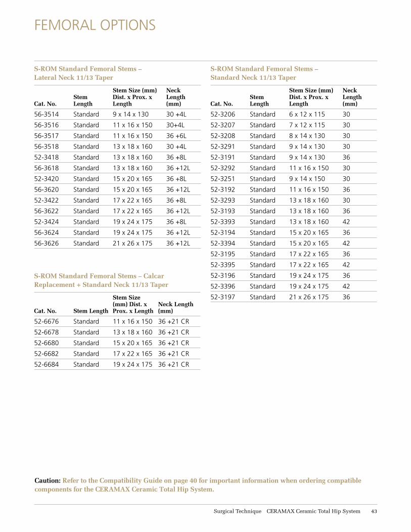
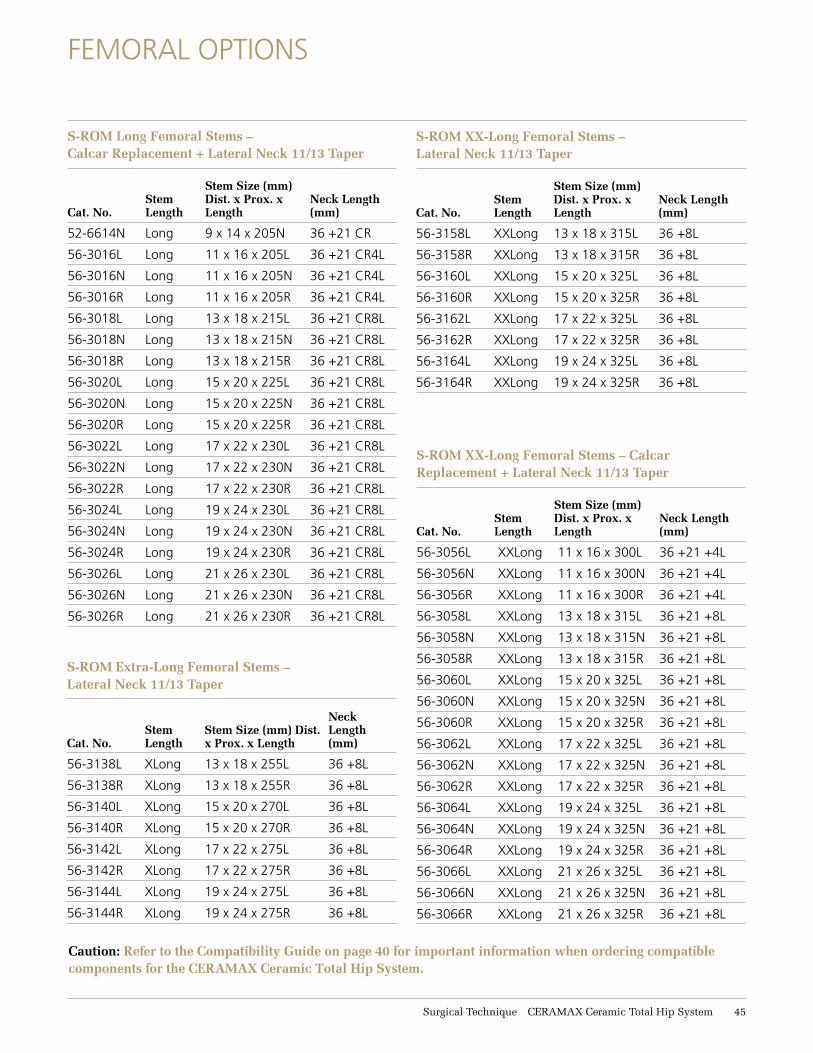
FEMORAL OPTIONS
Caution: Refer to the Compatibility Guide on page 40 for important information when ordering compatible components for the CERAMAX Ceramic Total Hip System.
S-ROM Standard Femoral Stems – Lateral Neck 11/13 Taper
Cat. No.Stem Length
Stem Size (mm) Dist. x Prox. x Length
Neck Length (mm)
56-3514 Standard 9 x 14 x 130 30 +4L
56-3516 Standard 11 x 16 x 150 30+4L
56-3517 Standard 11 x 16 x 150 36 +6L
56-3518 Standard 13 x 18 x 160 30 +4L
52-3418 Standard 13 x 18 x 160 36 +8L
56-3618 Standard 13 x 18 x 160 36 +12L
52-3420 Standard 15 x 20 x 165 36 +8L
56-3620 Standard 15 x 20 x 165 36 +12L
52-3422 Standard 17 x 22 x 165 36 +8L
56-3622 Standard 17 x 22 x 165 36 +12L
52-3424 Standard 19 x 24 x 175 36 +8L
56-3624 Standard 19 x 24 x 175 36 +12L
56-3626 Standard 21 x 26 x 175 36 +12L
S-ROM Standard Femoral Stems – Calcar Replacement + Standard Neck 11/13 Taper
Cat. No. Stem Length
Stem Size (mm) Dist. x Prox. x Length
Neck Length (mm)
52-6676 Standard 11 x 16 x 150 36 +21 CR
52-6678 Standard 13 x 18 x 160 36 +21 CR
52-6680 Standard 15 x 20 x 165 36 +21 CR
52-6682 Standard 17 x 22 x 165 36 +21 CR
52-6684 Standard 19 x 24 x 175 36 +21 CR
S-ROM Standard Femoral Stems – Standard Neck 11/13 Taper
Cat. No.Stem Length
Stem Size (mm) Dist. x Prox. x Length
Neck Length (mm)
52-3206 Standard 6 x 12 x 115 30
52-3207 Standard 7 x 12 x 115 30
52-3208 Standard 8 x 14 x 130 30
52-3291 Standard 9 x 14 x 130 30
52-3191 Standard 9 x 14 x 130 36
52-3292 Standard 11 x 16 x 150 30
52-3251 Standard 9 x 14 x 150 30
52-3192 Standard 11 x 16 x 150 36
52-3293 Standard 13 x 18 x 160 30
52-3193 Standard 13 x 18 x 160 36
52-3393 Standard 13 x 18 x 160 42
52-3194 Standard 15 x 20 x 165 36
52-3394 Standard 15 x 20 x 165 42
52-3195 Standard 17 x 22 x 165 36
52-3395 Standard 17 x 22 x 165 42
52-3196 Standard 19 x 24 x 175 36
52-3396 Standard 19 x 24 x 175 42
52-3197 Standard 21 x 26 x 175 36
Surgical Technique CERAMAX Ceramic Total Hip System 13
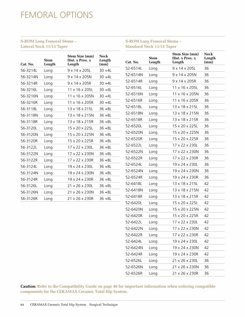
Caution: Refer to the Compatibility Guide on page 40 for important information when ordering compatible components for the CERAMAX Ceramic Total Hip System.
S-ROM Long Femoral Stems – Lateral Neck 11/13 Taper
Cat. No.Stem Length
Stem Size (mm) Dist. x Prox. x Length
Neck Length (mm)
56-3214L Long 9 x 14 x 205L 30 +4L
56-3214N Long 9 x 14 x 205N 30 +4L
56-3214R Long 9 x 14 x 205R 30 +4L
56-3216L Long 11 x 16 x 205L 30 +4L
56-3216N Long 11 x 16 x 205N 30 +4L
56-3216R Long 11 x 16 x 205R 30 +4L
56-3118L Long 13 x 18 x 215L 36 +8L
56-3118N Long 13 x 18 x 215N 36 +8L
56-3118R Long 13 x 18 x 215R 36 +8L
56-3120L Long 15 x 20 x 225L 36 +8L
56-3120N Long 15 x 20 x 225N 36 +8L
56-3120R Long 15 x 20 x 225R 36 +8L
56-3122L Long 17 x 22 x 230L 36 +8L
56-3122N Long 17 x 22 x 230N 36 +8L
56-3122R Long 17 x 22 x 230R 36 +8L
56-3124L Long 19 x 24 x 230L 36 +8L
56-3124N Long 19 x 24 x 230N 36 +8L
56-3124R Long 19 x 24 x 230R 36 +8L
56-3126L Long 21 x 26 x 230L 36 +8L
56-3126N Long 21 x 26 x 230N 36 +8L
56-3126R Long 21 x 26 x 230R 36 +8L
S-ROM Long Femoral Stems – Standard Neck 11/13 Taper
Cat. No.Stem Length
Stem Size (mm) Dist. x Prox. x Length
Neck Length (mm)
52-6514L Long 9 x 14 x 205L 36
52-6514N Long 9 x 14 x 205N 36
52-6514R Long 9 x 14 x 205R 36
52-6516L Long 11 x 16 x 205L 36
52-6516N Long 11 x 16 x 205N 36
52-6516R Long 11 x 16 x 205R 36
52-6518L Long 13 x 18 x 215L 36
52-6518N Long 13 x 18 x 215N 36
52-6518R Long 13 x 18 x 215R 36
52-6520L Long 15 x 20 x 225L 36
52-6520N Long 15 x 20 x 225N 36
52-6520R Long 15 x 20 x 225R 36
52-6522L Long 17 x 22 x 230L 36
52-6522N Long 17 x 22 x 230N 36
52-6522R Long 17 x 22 x 230R 36
52-6524L Long 19 x 24 x 230L 36
52-6524N Long 19 x 24 x 230N 36
52-6524R Long 19 x 24 x 230R 36
52-6418L Long 13 x 18 x 215L 42
52-6418N Long 13 x 18 x 215N 42
52-6418R Long 13 x 18 x 215R 42
52-6420L Long 15 x 20 x 225L 42
52-6420N Long 15 x 20 x 225N 42
52-6420R Long 15 x 20 x 225R 42
52-6422L Long 17 x 22 x 230L 42
52-6422N Long 17 x 22 x 230N 42
52-6422R Long 17 x 22 x 230R 42
52-6424L Long 19 x 24 x 230L 42
52-6424N Long 19 x 24 x 230N 42
52-6424R Long 19 x 24 x 230R 42
52-6526L Long 21 x 26 x 230L 36
52-6526N Long 21 x 26 x 230N 36
52-6526R Long 21 x 26 x 230R 36
FEMORAL OPTIONS
11 CERAMAX Ceramic Total Hip System Surgical Technique
FEMORAL OPTIONS
S-ROM Extra-Long Femoral Stems – Lateral Neck 11/13 Taper
Cat. No.Stem Length
Stem Size (mm) Dist. x Prox. x Length
Neck Length (mm)
56-3138L XLong 13 x 18 x 255L 36 +8L
56-3138R XLong 13 x 18 x 255R 36 +8L
56-3140L XLong 15 x 20 x 270L 36 +8L
56-3140R XLong 15 x 20 x 270R 36 +8L
56-3142L XLong 17 x 22 x 275L 36 +8L
56-3142R XLong 17 x 22 x 275R 36 +8L
56-3144L XLong 19 x 24 x 275L 36 +8L
56-3144R XLong 19 x 24 x 275R 36 +8L
S-ROM Long Femoral Stems – Calcar Replacement + Lateral Neck 11/13 Taper
Cat. No.Stem Length
Stem Size (mm) Dist. x Prox. x Length
Neck Length (mm)
52-6614N Long 9 x 14 x 205N 36 +21 CR
56-3016L Long 11 x 16 x 205L 36 +21 CR4L
56-3016N Long 11 x 16 x 205N 36 +21 CR4L
56-3016R Long 11 x 16 x 205R 36 +21 CR4L
56-3018L Long 13 x 18 x 215L 36 +21 CR8L
56-3018N Long 13 x 18 x 215N 36 +21 CR8L
56-3018R Long 13 x 18 x 215R 36 +21 CR8L
56-3020L Long 15 x 20 x 225L 36 +21 CR8L
56-3020N Long 15 x 20 x 225N 36 +21 CR8L
56-3020R Long 15 x 20 x 225R 36 +21 CR8L
56-3022L Long 17 x 22 x 230L 36 +21 CR8L
56-3022N Long 17 x 22 x 230N 36 +21 CR8L
56-3022R Long 17 x 22 x 230R 36 +21 CR8L
56-3024L Long 19 x 24 x 230L 36 +21 CR8L
56-3024N Long 19 x 24 x 230N 36 +21 CR8L
56-3024R Long 19 x 24 x 230R 36 +21 CR8L
56-3026L Long 21 x 26 x 230L 36 +21 CR8L
56-3026N Long 21 x 26 x 230N 36 +21 CR8L
56-3026R Long 21 x 26 x 230R 36 +21 CR8L
S-ROM XX-Long Femoral Stems – Calcar Replacement + Lateral Neck 11/13 Taper
Cat. No.Stem Length
Stem Size (mm) Dist. x Prox. x Length
Neck Length (mm)
56-3056L XXLong 11 x 16 x 300L 36 +21 +4L
56-3056N XXLong 11 x 16 x 300N 36 +21 +4L
56-3056R XXLong 11 x 16 x 300R 36 +21 +4L
56-3058L XXLong 13 x 18 x 315L 36 +21 +8L
56-3058N XXLong 13 x 18 x 315N 36 +21 +8L
56-3058R XXLong 13 x 18 x 315R 36 +21 +8L
56-3060L XXLong 15 x 20 x 325L 36 +21 +8L
56-3060N XXLong 15 x 20 x 325N 36 +21 +8L
56-3060R XXLong 15 x 20 x 325R 36 +21 +8L
56-3062L XXLong 17 x 22 x 325L 36 +21 +8L
56-3062N XXLong 17 x 22 x 325N 36 +21 +8L
56-3062R XXLong 17 x 22 x 325R 36 +21 +8L
56-3064L XXLong 19 x 24 x 325L 36 +21 +8L
56-3064N XXLong 19 x 24 x 325N 36 +21 +8L
56-3064R XXLong 19 x 24 x 325R 36 +21 +8L
56-3066L XXLong 21 x 26 x 325L 36 +21 +8L
56-3066N XXLong 21 x 26 x 325N 36 +21 +8L
56-3066R XXLong 21 x 26 x 325R 36 +21 +8L
S-ROM XX-Long Femoral Stems – Lateral Neck 11/13 Taper
Cat. No.Stem Length
Stem Size (mm) Dist. x Prox. x Length
Neck Length (mm)
56-3158L XXLong 13 x 18 x 315L 36 +8L
56-3158R XXLong 13 x 18 x 315R 36 +8L
56-3160L XXLong 15 x 20 x 325L 36 +8L
56-3160R XXLong 15 x 20 x 325R 36 +8L
56-3162L XXLong 17 x 22 x 325L 36 +8L
56-3162R XXLong 17 x 22 x 325R 36 +8L
56-3164L XXLong 19 x 24 x 325L 36 +8L
56-3164R XXLong 19 x 24 x 325R 36 +8L
Caution: Refer to the Compatibility Guide on page 40 for important information when ordering compatible components for the CERAMAX Ceramic Total Hip System.
Surgical Technique CERAMAX Ceramic Total Hip System 11
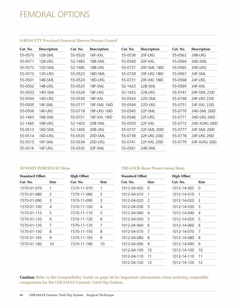
FEMORAL OPTIONS
Caution: Refer to the Compatibility Guide on page 40 for important information when ordering compatible components for the CERAMAX Ceramic Total Hip System.
S-ROM ZTT Proximal Femoral Sleeves Porous Coated
Cat. No. Description
55-0570 12B-SML
55-0571 12B-LRG
55-0572 12D-SML
55-0573 12D-LRG
55-0501 14B-SML
55-0502 14B-LRG
55-0503 14D-SML
55-0504 14D-LRG
55-0505 14F-SML
55-0506 14F-LRG
52-1463 16B-SML
52-1465 16B-LRG
55-0513 16D-SML
55-0514 16D-LRG
55-0515 16F-SML
55-0516 16F-LRG
Cat. No. Description
55-0520 16F-XXL
52-1483 18B-SML
52-1485 18B-LRG
55-0523 18D-SML
55-0524 18D-LRG
55-0525 18F-SML
55-0526 18F-LRG
55-0530 18F-XXL
55-0717 18F-SML 16ID
55-0718 18F-LRG 16ID
55-0721 18F-XXL 16ID
52-1403 20B-SML
52-1405 20B-LRG
55-0533 20D-SML
55-0534 20D-LRG
55-0535 20F-SML
Cat. No. Description
55-0536 20F-LRG
55-0540 20F-XXL
55-0727 20F-SML 18ID
55-0728 20F-LRG 18ID
55-0731 20F-XXL 18ID
52-1423 22B-SML
52-1425 22B-LRG
55-0543 22D-SML
55-0544 22D-LRG
55-0545 22F-SML
55-0546 22F-LRG
55-0550 22F-XXL
55-0737 22F-SML 20ID
55-0738 22F-LRG 20ID
55-0741 22F-XXL 20ID
55-0561 24B-SML
Cat. No. Description
55-0562 24B-LRG
55-0564 24D-SML
55-0565 24D-LRG
55-0567 24F-SML
55-0568 24F-LRG
55-0569 24F-XXL
55-0747 24F-SML 22ID
55-0748 24F-LRG 22ID
55-0751 24F-XXL 22ID
55-0770 24D-SML 26ID
55-0771 24D-LRG 26ID
55-0772 24D-XLRG 26ID
55-0777 24F-SML 26ID
55-0778 24F-LRG 26ID
55-0779 24F-XLRG 26ID
SUMMIT POROCOAT Stem
Standard Offset
Cat. No. Size
1570-01-070 1
1570-01-080 2
1570-01-090 3
1570-01-100 4
1570-01-110 5
1570-01-120 6
1570-01-135 7
1570-01-150 8
1570-01-165 9
1570-01-180 10
High Offset
Cat. No. Size
1570-11-070 1
1570-11-080 2
1570-11-090 3
1570-11-100 4
1570-11-110 5
1570-11-120 6
1570-11-135 7
1570-11-150 8
1570-11-165 9
1570-11-180 10
TRI-LOCK Bone Preservation Stem
Standard Offset
Cat. No. Size
1012-04-005 0
1012-04-010 1
1012-04-020 2
1012-04-030 3
1012-04-040 4
1012-04-050 5
1012-04-060 6
1012-04-070 7
1012-04-080 8
1012-04-090 9
1012-04-100 10
1012-04-110 11
1012-04-120 12
High Offset
Cat. No. Size
1012-14-005 0
1012-14-010 1
1012-14-020 2
1012-14-030 3
1012-14-040 4
1012-14-050 5
1012-14-060 6
1012-14-070 7
1012-14-080 8
1012-14-090 9
1012-14-100 10
1012-14-110 11
1012-14-120 12
16 CERAMAX Ceramic Total Hip System Surgical Technique
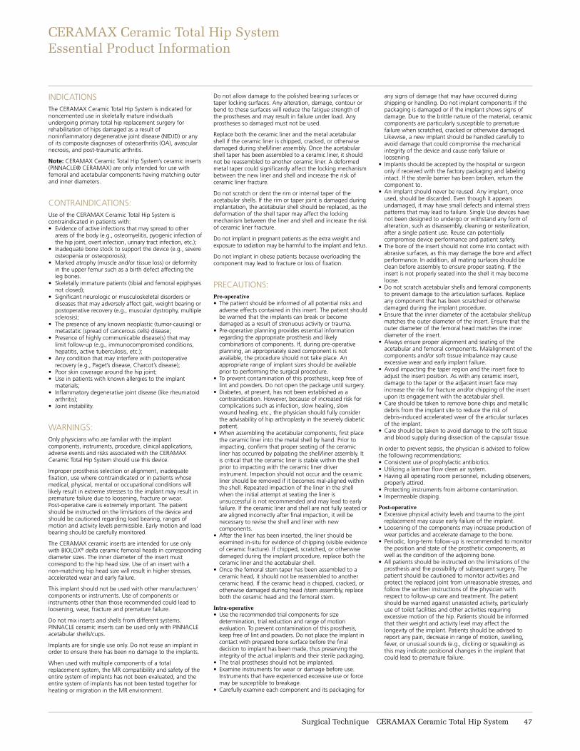
INDICATIONSThe CERAMAX Ceramic Total Hip System is indicated for noncemented use in skeletally mature individuals undergoing primary total hip replacement surgery for rehabilitation of hips damaged as a result of noninflammatory degenerative joint disease (NIDJD) or any of its composite diagnoses of osteoarthritis (OA), avascular necrosis, and post-traumatic arthritis.
Note: CERAMAX Ceramic Total Hip System’s ceramic inserts (PINNACLE® CERAMAX) are only intended for use with femoral and acetabular components having matching outer and inner diameters.
CONTRAINDICATIONS: Use of the CERAMAX Ceramic Total Hip System is contraindicated in patients with:• Evidence of active infections that may spread to other
areas of the body (e.g., osteomyelitis, pyogenic infection of the hip joint, overt infection, urinary tract infection, etc.);
• Inadequate bone stock to support the device (e.g., severe osteopenia or osteoporosis);
• Marked atrophy (muscle and/or tissue loss) or deformity in the upper femur such as a birth defect affecting the leg bones.
• Skeletally immature patients (tibial and femoral epiphyses not closed);
• Significant neurologic or musculoskeletal disorders or diseases that may adversely affect gait, weight bearing or postoperative recovery (e.g., muscular dystrophy, multiple sclerosis);
• The presence of any known neoplastic (tumor-causing) or metastatic (spread of cancerous cells) disease;
• Presence of highly communicable disease(s) that may limit follow-up (e.g., immunocompromised conditions, hepatitis, active tuberculosis, etc.);
• Any condition that may interfere with postoperative recovery (e.g., Paget’s disease, Charcot’s disease);
• Poor skin coverage around the hip joint;• Use in patients with known allergies to the implant
materials;• Inflammatory degenerative joint disease (like rheumatoid
arthritis);• Joint instability.
WARNINGS: Only physicians who are familiar with the implant components, instruments, procedure, clinical applications, adverse events and risks associated with the CERAMAX Ceramic Total Hip System should use this device.
Improper prosthesis selection or alignment, inadequate fixation, use where contraindicated or in patients whose medical, physical, mental or occupational conditions will likely result in extreme stresses to the implant may result in premature failure due to loosening, fracture or wear. Post-operative care is extremely important. The patient should be instructed on the limitations of the device and should be cautioned regarding load bearing, ranges of motion and activity levels permissible. Early motion and load bearing should be carefully monitored.
The CERAMAX ceramic inserts are intended for use only with BIOLOX® delta ceramic femoral heads in corresponding diameter sizes. The inner diameter of the insert must correspond to the hip head size. Use of an insert with a non-matching hip head size will result in higher stresses, accelerated wear and early failure.
This implant should not be used with other manufacturers’ components or instruments. Use of components or instruments other than those recommended could lead to loosening, wear, fracture and premature failure.
Do not mix inserts and shells from different systems. PINNACLE ceramic inserts can be used only with PINNACLE acetabular shells/cups.
Implants are for single use only. Do not reuse an implant in order to ensure there has been no damage to the implants.
When used with multiple components of a total replacement system, the MR compatibility and safety of the entire system of implants has not been evaluated, and the entire system of implants has not been tested together for heating or migration in the MR environment.
Do not allow damage to the polished bearing surfaces or taper locking surfaces. Any alteration, damage, contour or bend to these surfaces will reduce the fatigue strength of the prostheses and may result in failure under load. Any prostheses so damaged must not be used.
Replace both the ceramic liner and the metal acetabular shell if the ceramic liner is chipped, cracked, or otherwise damaged during shell/liner assembly. Once the acetabular shell taper has been assembled to a ceramic liner, it should not be reassembled to another ceramic liner. A deformed metal taper could significantly affect the locking mechanism between the new liner and shell and increase the risk of ceramic liner fracture.
Do not scratch or dent the rim or internal taper of the acetabular shells. If the rim or taper joint is damaged during implantation, the acetabular shell should be replaced, as the deformation of the shell taper may affect the locking mechanism between the liner and shell and increase the risk of ceramic liner fracture.
Do not implant in pregnant patients as the extra weight and exposure to radiation may be harmful to the implant and fetus.
Do not implant in obese patients because overloading the component may lead to fracture or loss of fixation.
PRECAUTIONS:Pre-operative• The patient should be informed of all potential risks and
adverse effects contained in this insert. The patient should be warned that the implants can break or become damaged as a result of strenuous activity or trauma.
• Pre-operative planning provides essential information regarding the appropriate prosthesis and likely combinations of components. If, during pre-operative planning, an appropriately sized component is not available, the procedure should not take place. An appropriate range of implant sizes should be available prior to performing the surgical procedure.
• To prevent contamination of this prosthesis, keep free of lint and powders. Do not open the package until surgery.
• Diabetes, at present, has not been established as a contraindication. However, because of increased risk for complications such as infection, slow healing, slow wound healing, etc., the physician should fully consider the advisability of hip arthroplasty in the severely diabetic patient.
• When assembling the acetabular components, first place the ceramic liner into the metal shell by hand. Prior to impacting, confirm that proper seating of the ceramic liner has occurred by palpating the shell/liner assembly. It is critical that the ceramic liner is stable within the shell prior to impacting with the ceramic liner driver instrument. Impaction should not occur and the ceramic liner should be removed if it becomes mal-aligned within the shell. Repeated impaction of the liner in the shell when the initial attempt at seating the liner is unsuccessful is not recommended and may lead to early failure. If the ceramic liner and shell are not fully seated or are aligned incorrectly after final impaction, it will be necessary to revise the shell and liner with new components.
• After the liner has been inserted, the liner should be examined in-situ for evidence of chipping (visible evidence of ceramic fracture). If chipped, scratched, or otherwise damaged during the implant procedure, replace both the ceramic liner and the acetabular shell.
• Once the femoral stem taper has been assembled to a ceramic head, it should not be reassembled to another ceramic head. If the ceramic head is chipped, cracked, or otherwise damaged during head /stem assembly, replace both the ceramic head and the femoral stem.
Intra-operative• Use the recommended trial components for size
determination, trial reduction and range of motion evaluation. To prevent contamination of this prosthesis, keep free of lint and powders. Do not place the implant in contact with prepared bone surface before the final decision to implant has been made, thus preserving the integrity of the actual implants and their sterile packaging.
• The trial prostheses should not be implanted.• Examine instruments for wear or damage before use.
Instruments that have experienced excessive use or force may be susceptible to breakage.
• Carefully examine each component and its packaging for
any signs of damage that may have occurred during shipping or handling. Do not implant components if the packaging is damaged or if the implant shows signs of damage. Due to the brittle nature of the material, ceramic components are particularly susceptible to premature failure when scratched, cracked or otherwise damaged. Likewise, a new implant should be handled carefully to avoid damage that could compromise the mechanical integrity of the device and cause early failure or loosening.
• Implants should be accepted by the hospital or surgeon only if received with the factory packaging and labeling intact. If the sterile barrier has been broken, return the component to.
• An implant should never be reused. Any implant, once used, should be discarded. Even though it appears undamaged, it may have small defects and internal stress patterns that may lead to failure. Single Use devices have not been designed to undergo or withstand any form of alteration, such as disassembly, cleaning or resterilization, after a single patient use. Reuse can potentially compromise device performance and patient safety.
• The bore of the insert should not come into contact with abrasive surfaces, as this may damage the bore and affect performance. In addition, all mating surfaces should be clean before assembly to ensure proper seating. If the insert is not properly seated into the shell it may become loose.
• Do not scratch acetabular shells and femoral components to prevent damage to the articulation surfaces. Replace any component that has been scratched or otherwise damaged during the implant procedure.
• Ensure that the inner diameter of the acetabular shell/cup matches the outer diameter of the insert. Ensure that the outer diameter of the femoral head matches the inner diameter of the insert.
• Always ensure proper alignment and seating of the acetabular and femoral components. Malalignment of the components and/or soft tissue imbalance may cause excessive wear and early implant failure.
• Avoid impacting the taper region and the insert face to adjust the insert position. As with any ceramic insert, damage to the taper or the adjacent insert face may increase the risk for fracture and/or chipping of the insert upon its engagement with the acetabular shell.
• Care should be taken to remove bone chips and metallic debris from the implant site to reduce the risk of debris-induced accelerated wear of the articular surfaces of the implant.
• Care should be taken to avoid damage to the soft tissue and blood supply during dissection of the capsular tissue.
In order to prevent sepsis, the physician is advised to follow the following recommendations:• Consistent use of prophylactic antibiotics.• Utilizing a laminar flow clean air system.• Having all operating room personnel, including observers,
properly attired.• Protecting instruments from airborne contamination.• Impermeable draping.
Post-operative• Excessive physical activity levels and trauma to the joint
replacement may cause early failure of the implant.• Loosening of the components may increase production of
wear particles and accelerate damage to the bone.• Periodic, long-term follow-up is recommended to monitor
the position and state of the prosthetic components, as well as the condition of the adjoining bone.
• All patients should be instructed on the limitations of the prosthesis and the possibility of subsequent surgery. The patient should be cautioned to monitor activities and protect the replaced joint from unreasonable stresses, and follow the written instructions of the physician with respect to follow-up care and treatment. The patient should be warned against unassisted activity, particularly use of toilet facilities and other activities requiring excessive motion of the hip. Patients should be informed that their weight and activity level may affect the longevity of the implant. Patients should be advised to report any pain, decrease in range of motion, swelling, fever, or unusual sounds (e.g., clicking or squeaking) as this may indicate positional changes in the implant that could lead to premature failure.
CERAMAX Ceramic Total Hip System Essential Product Information
Surgical Technique CERAMAX Ceramic Total Hip System 17

DePuy Orthopaedics, Inc.700 Orthopaedic DriveWarsaw, IN 46582T. +1 (800) 366-8143
www.depuysynthes.com
© DePuy Orthopaedics, Inc. 2014. All rights reserved. 0612-90-511 (Rev. 3) 2/14
WARNING: In the USA, this product has labeling limitations. See package insert for complete information.
CAUTION: USA Law restricts these devices to sale by or on the order of a physician.
Not all products are currently available in all markets.
Biolox is a registered trademark of CeramTec GmbH