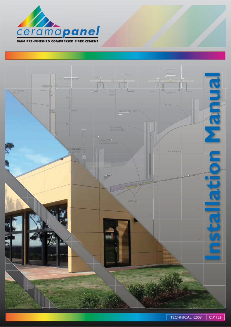
Ceramapanel Planning And Installation Manual
38
Ceramapanel ™ ExpressW all W W Ve r tical Gask et k k 6-20mm Exposed Head Screw W eather Seal W W compressed in hole and compressed ar ound screw thread Ceramapanel ™ sive ress s sW s all a a a a a a a a a a a a a a a a a a a a a a a a a a a a l al al l ll ll l l W W athe Se S S S S S S S S S S S S S S S S S S S S Se e e er S e ea e e e e e a al l l l l l l l l l l l l l l l -dr d illed h d l lled l h h h h h h h ho le o o o o o o o o o o o o o l por or or or or or or r r t t t t t t t Expr W ea W W ™ ™ ™ ™ ™ t t Pre- Pre l Cer amapanel k et k k E Expres W sW ll all W W W Hor iz ontal Gask posed ad ad Screw Screw W ll l l l l l l W Intermediate T T op Hat T T mapanel Intermed I Interm d ed ™ Exp Hea Hea E e Ce Ce Cer Ce C C C am es essW sW all all W W W W c cal al Gas Gask k et et k k k k ExpressW all W W T op T T Hat Exp Expre re Ve Ve r r r tic tic m* 10mm 45mm 1 Express ExpressW W all™ all™ W W W W T T op op T T T T Hat 1.15 Sarking ExpressW all W W T op Hat T T ExpressW all W W CSK Screw m* m* 45m 45mm m Hor Hor iz iz ont ontal al Gas G G k et k k tr tr tr tr r ip ip ip ip ip p ip ip ip Adhes Installation Manual TECHNICAL -2009 C.P 126
Transcript of Ceramapanel Planning And Installation Manual
Ceramapanel™
ExpressWall WWVertical Gasketkk6-20mm
Exposed Head Screw
Weather Seal WWcompressed in
hole and compressed around screw threadrr
Ceramapanel™
sive
ressssWs allaaaaaaaaaaaaaaaaaaaaaaaaaaaaa lalalllllllllWWathe SeSSSSSSSSSSSSSSSSSSSSSSeeeer Se eaeeeeeaalllllllllllllllllll
-drd illed hold dddllledl hhhhhhhholeoooooooooooool
pororororororororortttttttt
pExprWeaWW
™™™™™
tt
Pre-Pre
lCeramapanelrr
ketkkEExpres WsW llall WWWHorizontal Gask
posedadad ScrewScrew
W lllllllllW
IntermediateTTop HatTTmapanelIntermedIInterm ded™
ExpHeaHea
E
e CeCeCerCeCCCC am
esessWsWallall WWWWccalal GasGaskketetkkkk
ExpressWall WW TopTTHat
ExpExprereVeVerrrtictic
m*
10mm
45mm
1
ExpressExpressWWall™all™ WWWW TTopop TTTTHat 1.15
Sarking
ExpressWall WWTop HatTT
ExpressWall WWCSK Screw
m*m*45m45mmm
HorHorizizontontalal GasGG ketkk
trtrtrtrripipipipipipipipip
Adhes
Inst
alla
tio
n M
anua
l
TECHNICAL -2009 C.P 126
2
CERAMAPANEL™ 9MM PRE-FINISHED COMPRESSED FIBRE CEMENT
CONTENTS
Description 2
Applications 2
Commercial ExpressWall™ Advantages 3
Components 4 – 6
Design Considerations 7 – 12
Top Hat Framing 13 – 14
Panel Preparation 15 – 17
Panel Installation 18 – 21
Curved Façades 22
Construction Details 23 – 30
Fire Rated Wall Systems 31 – 34
Architectural Specification 35
Material Properties 36
Handling & Storage 37
Safety 37
Panel Cutting 37
Health & Safety 40
Guarantee 40
DESCRIPTION
Ceramapanel™ 9mm CFC façade system by Fair view Architectural P/L provides a versatile and durable facade which is suitable for an extensive range of commercial/industrial building types and institutional buildings such as Universities and Schools. Ceramapanel™ façade is a highly adaptive system which can be used to conceal most common structural materials such as masonry, precast concrete or steel and timber stud framing.
Ceramapanel™ is 9mm thick CFC finished in the highly durable Environflon or Inflonito coating systems and available in an unlimited colour range.
The panels are supported by vertical tophats and fixed using colour coded wafer head screws. The panels may be arranged in a variety of patterns and surface relief is produced by expressed joint finishing
APPLICATIONS
The Ceramapanel™ façade™ system has been designed to be used for external cladding buildings such as:
Considerations section of this brochure.
It however remains the responsibility of the building designer to verify the Ceramapanel™ façade™ system is suitable for the particular requirements of any given project.
The Ceramapanel™ façade™ System has excellent resistance to water penetration and high wind loads, and is suitable for exposed applications.
CERAMAPANEL™ 9MM PRE-FINISHED COMPRESSED FIBRE CEMENT
3
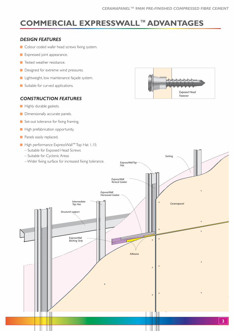
COMMERCIAL EXPRESSWALL™ ADVANTAGES
DESIGN FEATURES
Colour coded wafer head screws fixing system.
Expressed joint appearance.
Tested weather resistance.
Designed for extreme wind pressures.
Lightweight, low maintenance façade system.
Suitable for curved applications.
CONSTRUCTION FEATURES
Highly durable gaskets.
Dimensionally accurate panels.
Set-out tolerance for fixing framing.
High prefabrication opportunity.
Panels easily replaced.
High performance ExpressWall™ Top Hat 1.15:– Suitable for Exposed Head Screws – Suitable for Cyclonic Areas – Wider fixing surface for increased fixing tolerance.
ExpressWall Backing Strip
Structural support
ExpressWall Horizontal Gasket
ExpressWall Vertical Gasket
Adhesive
ExpressWall Top Hat
Intermediate Top Hat
Sarking
Ceramapanel
Exposed HeadExposed HeadFastener
4
CERAMAPANEL™ 9MM PRE-FINISHED COMPRESSED FIBRE CEMENT
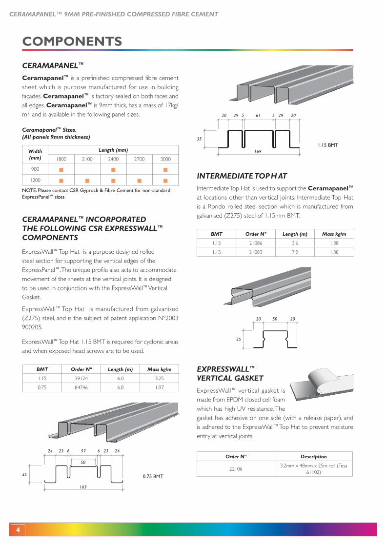
INTERMEDIATE TOP H AT
Intermediate Top Hat is used to support the Ceramapanel™ at locations other than vertical joints. Intermediate Top Hat is a Rondo rolled steel section which is manufactured from
20 2050
35
Ceramapanel™ Sizes. (All panels 9mm thickness)
Width(mm)
Length (mm)
1800 2100 2400 2700 3000
900
1200
NOTE: Please contact CSR Gyprock & Fibre Cement for non-standard ExpressPanel™ sizes.
BMT Order Nº Length (m) Mass kg/m
1.15 39124 6.0 3.25
0.75 84746 6.0 1.97
BMT Order Nº Length (m) Mass kg/m
1.15 21086 3.6 1.38
1.15 21083 7.2 1.38
20 20295529
35
61
1691.15 BMT
24 24236623
35
57
50
163
0.75 BMT
COMPONENTS
CERAMAPANEL™
Ceramapanel™ is a prefinished compressed fibre cement sheet which is purpose manufactured for use in building façades. Ceramapanel™ is factory sealed on both faces and all edges. Ceramapanel™ is 9mm thick, has a mass of 17kg/m2, and is available in the following panel sizes.
CERAMAPANEL™ INCORPORATED THE FOLLOWING CSR EXPRESSWALL™
COMPONENTS
ExpressWall™ Top Hat is a purpose designed rolled steel section for supporting the vertical edges of the ExpressPanel™. The unique profile also acts to accommodate movement of the sheets at the vertical joints. It is designed to be used in conjunction with the ExpressWall™ Vertical Gasket.
ExpressWall™ Top Hat is manufactured from galvanised (Z275) steel, and is the subject of patent application Nº2003 900205.
ExpressWall™
and when exposed head screws are to be used.
EXPRESSWALL™ VERTICAL GASKET
ExpressWall™ ver tical gasket is made from EPDM closed cell foam which has high UV resistance. The gasket has adhesive on one side (with a release paper), and is adhered to the ExpressWall™ Top Hat to prevent moisture entry at vertical joints.
Order Nº Description
221063.2mm x 48mm x 25m roll (Tesa
61102)
CERAMAPANEL™ 9MM PRE-FINISHED COMPRESSED FIBRE CEMENT
5
EXPRESSWALL™ BACKING STRIP
ExpressWall™
section designed to support the gasket and/or sealant behind the horizontal expressed joints . ExpressWall™
manufactured from high tensile Colorbond steel, and is black in colour.
Order Nº Length
21089 1194mm
21088 2394mm
21087 2994mm
60mm
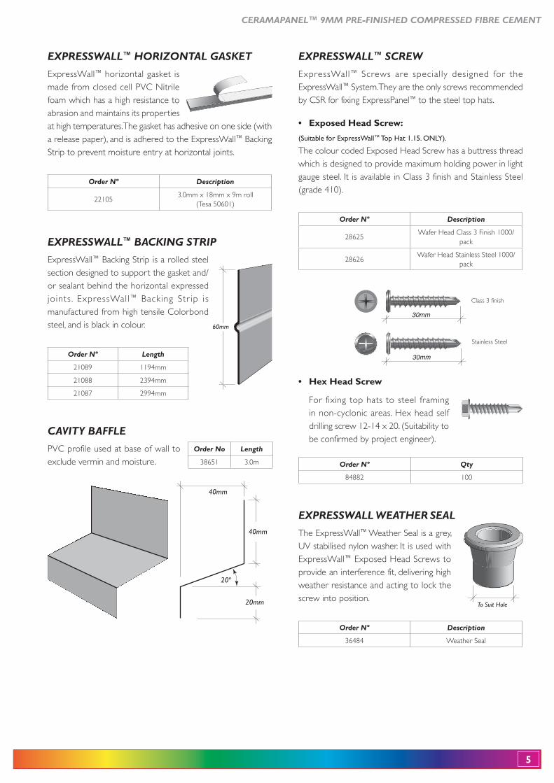
EXPRESSWALL™ HORIZONTAL GASKET
ExpressWall™ horizontal gasket is made from closed cell PVC Nitrile foam which has a high resistance to abrasion and maintains its properties at high temperatures. The gasket has adhesive on one side (with a release paper), and is adhered to the ExpressWall™
Strip to prevent moisture entry at horizontal joints.
Order Nº Description
221053.0mm x 18mm x 9m roll
(Tesa 50601)
EXPRESSWALL™ SCREW
ExpressWall™ Screws are special ly designed for the ExpressWall™ System. They are the only screws recommended by CSR for fixing ExpressPanel™ to the steel top hats.
30mm
Stainless Steel
30mm
Class 3 finish
(Suitable for ExpressWall™ Top Hat 1.15. ONLY).
The colour coded Exposed Head Screw has a buttress thread which is designed to provide maximum holding power in light gauge steel. It is available in Class 3 finish and Stainless Steel (grade 410).
Order Nº Description
28625Wafer Head Class 3 Finish 1000/
pack
28626Wafer Head Stainless Steel 1000/
pack
Order Nº Qty
84882 100
For fixing top hats to steel framing in non-cyclonic areas. Hex head self drilling screw 12-14 x 20. (Suitability to be confirmed by project engineer).
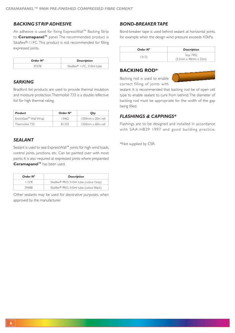
CAVITY BAFFLE
PVC profile used at base of wall to exclude vermin and moisture.
40mm
20mm
20º
40mm
Order No Length
38651 3.0m
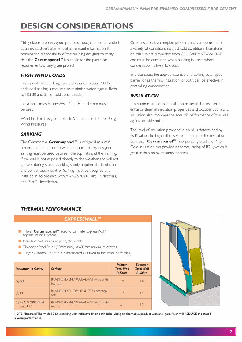
EXPRESSWALL WEATHER SEAL
The ExpressWall™ Weather Seal is a grey, UV stabilised nylon washer. It is used with ExpressWall™ Exposed Head Screws to provide an interference fit, delivering high weather resistance and acting to lock the screw into position.
Order Nº Description
36484 Weather Seal
To Suit Hole
6
CERAMAPANEL™ 9MM PRE-FINISHED COMPRESSED FIBRE CEMENT
SEALANT
Sealant is used to seal ExpressWall™ joints for high wind loads, control joints, junctions, etc. Can be painted over with most paints. It is also required at expressed joints where prepainted Ceramapanel™ has been used.
Order Nº Description
11378 Sikaflex®
39488 Sikaflex®
approved by the manufacturer.
FLASHINGS & CAPPINGS*
Flashings are to be designed and installed in accordance
*Not supplied by CSR.
BACKING STRIP ADHESIVE
An adhesive is used for fixing ExpressWall™
to Ceramapanel™ panel. The recommended product is Sikaflex®-11FC. This product is not recommended for filling expressed joints.
Order Nº Description
39378 Sikaflex® 11FC, 310ml tube
SARKING
and moisture protection. Thermofoil 733 is a double reflective foil for high thermal rating.
Product Order Nº Qty
EnviroSeal™ Wall Wrap 13462 1350mm x 20m roll
Thermofoil 733 81333 1350mm x 60m roll
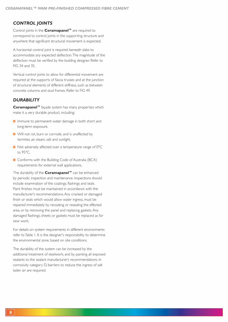
BACKING ROD*
correct fil l ing of joints with sealant. It is recommended that backing rod be of open cell type to enable sealant to cure from behind. The diameter of backing rod must be appropriate for the width of the gap being filled.
BOND-BREAKER TAPE
for example when the design wind pressure exceeds 4.0kPa.
Order Nº Description
13172Tesa 7492
(3.2mm x 48mm x 25m).
CERAMAPANEL™ 9MM PRE-FINISHED COMPRESSED FIBRE CEMENT
7
THERMAL PERFORMANCE
This guide represents good practice, though it is not intended as an exhaustive statement of all relevant information. It remains the responsibility of the building designer to verify that the Ceramapanel™ is suitable for the particular requirements of any given project.
HIGH WIND LOADS
In areas where the design wind pressures exceed 4.0kPa, additional sealing is required to minimise water ingress. Refer to FIG 30 and 31 for additional details.
In cyclonic areas ExpressWall™ Top Hat 1.15mm must be used.
Wind loads in this guide refer to ‘Ultimate Limit State Design Wind Pressures’.
SARKING
The Commercial Ceramapanel™ is designed as a rain screen, and if exposed to weather, appropriately designed sarking must be used between the top hats and the framing. If the wall is not exposed directly to the weather and will not get wet during storms, sarking is only required for insulation and condensation control. Sarking must be designed and installed in accordance with AS/NZS 4200 Part 1 : Materials, and Part 2 : Installation.
Condensation is a complex problem, and can occur under a variety of conditions, not just cold conditions. Literature
and must be consulted when building in areas where condensation is likely to occur.
In these cases, the appropriate use of a sarking as a vapour barrier or as thermal insulation, or both, can be effective in controlling condensation.
INSULATION
It is recommended that insulation materials be installed to enhance thermal insulation properties and occupant comfort. Insulation also improves the acoustic performance of the wall against outside noise.
The level of insulation provided in a wall is determined by its R-value. The higher the R-value the greater the insulation provided. Ceramapanel™
Gold Insulation can provide a thermal rating of R2.1, which is greater than many masonry systems.
EXPRESSWALL™
1 layer Ceramapanel™ fixed to Cemintel ExpressWall™ top hat framing system.
Insulation and Sarking as per system table.
Timber or Steel Studs (90mm min.) at 600mm maximum centres.
Insulation in Cavity SarkingWinter
Total Wall R-Value
Summer Total Wall R-Value
(a) Nil top hats
1.2 1.0
(b) Nilhats
1.7 1.4
batts R1.5 top hats2.1 1.9
NOTE: *Bradford Thermofoil 733 is sarking with reflective finish both sides. Using an alternative product with anti-glare finish will REDUCE the stated R-value performance.
DESIGN CONSIDERATIONS
8
CERAMAPANEL™ 9MM PRE-FINISHED COMPRESSED FIBRE CEMENT
CONTROL JOINTS
Control joints in the Ceramapanel™ are required to correspond to control joints in the supporting structure and anywhere that significant structural movement is expected.
A horizontal control joint is required beneath slabs to accommodate any expected deflection. The magnitude of the deflection must be verified by the building designer. Refer to FIG 34 and 35.
Vertical control joints to allow for differential movement are required at the supports of fascia trusses and at the junction of structural elements of different stiffness, such as between concrete columns and stud frames. Refer to FIG 49.
DURABILITY
Ceramapanel™ façade system has many properties which make it a very durable product, including:
Immune to permanent water damage in both short and long-term exposure.
Will not rot, burn or corrode, and is unaffected by termites, air, steam, salt and sunlight.
Not adversely affected over a temperature range of 0ºC to 95ºC.
requirements for external wall applications.
The durability of the Ceramapanel™ can be enhanced by periodic inspection and maintenance. Inspections should include examination of the coatings, flashings and seals. Paint finishes must be maintained in accordance with the manufacturer’s recommendations. Any cracked or damaged finish or seals which would allow water ingress, must be repaired immediately by recoating or resealing the effected area, or by removing the panel and replacing gaskets. Any damaged flashings, sheets or gaskets must be replaced as for new work.
For details on system requirements in different environments refer to Table 1. It is the designer's responsibility to determine the environmental zone, based on site conditions.
The durability of the system can be increased by the additional treatment of steelwork, and by painting all exposed sealants to the sealant manufacturer’s recommendations. In corrosivity category D, barriers to reduce the ingress of salt laden air are required.
CERAMAPANEL™ 9MM PRE-FINISHED COMPRESSED FIBRE CEMENT
9
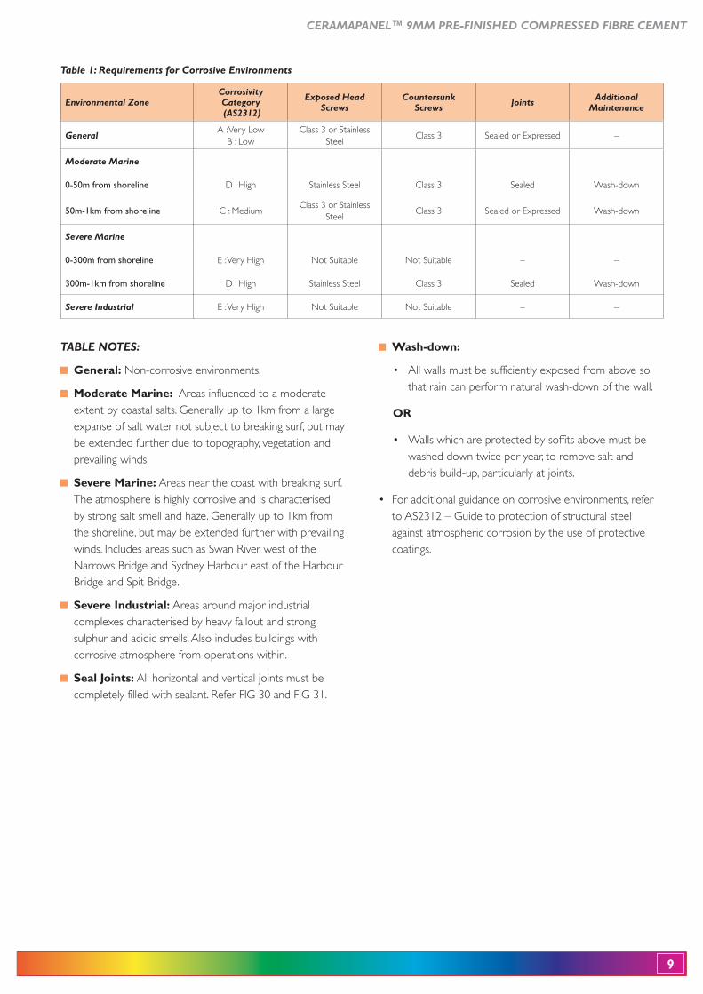
Table 1: Requirements for Corrosive Environments
TABLE NOTES:
Non-corrosive environments.
Areas influenced to a moderate extent by coastal salts. Generally up to 1km from a large expanse of salt water not subject to breaking surf, but may be extended further due to topography, vegetation and prevailing winds.
Areas near the coast with breaking surf. The atmosphere is highly corrosive and is characterised by strong salt smell and haze. Generally up to 1km from the shoreline, but may be extended further with prevailing winds. Includes areas such as Swan River west of the
Areas around major industrial complexes characterised by heavy fallout and strong sulphur and acidic smells. Also includes buildings with corrosive atmosphere from operations within.
All horizontal and vertical joints must be completely filled with sealant. Refer FIG 30 and FIG 31.
that rain can perform natural wash-down of the wall.
OR
washed down twice per year, to remove salt and debris build-up, particularly at joints.
to AS2312 – Guide to protection of structural steel against atmospheric corrosion by the use of protective coatings.
Environmental ZoneCorrosivity Category (AS2312)
Exposed Head Screws
Countersunk Screws Joints Additional
Maintenance
GeneralA : Very Low Class 3 or Stainless
SteelClass 3 Sealed or Expressed –
Moderate Marine
0-50m from shoreline D : High Stainless Steel Class 3 Sealed Wash-down
50m-1km from shoreline C : MediumClass 3 or Stainless
SteelClass 3 Sealed or Expressed Wash-down
Severe Marine
0-300m from shoreline E : Very High Not Suitable Not Suitable – –
300m-1km from shoreline D : High Stainless Steel Class 3 Sealed Wash-down
Severe Industrial E : Very High Not Suitable Not Suitable – –
10
CERAMAPANEL™ 9MM PRE-FINISHED COMPRESSED FIBRE CEMENT
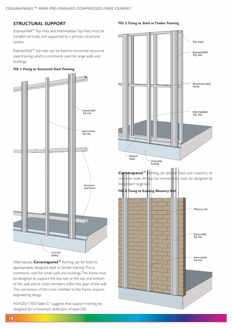
STRUCTURAL SUPPORT
ExpressWall™ Top Hats and Intermediate Top Hats must be installed vertically, and supported by a primary structural system.
ExpressWall™ top hats can be fixed to horizontal structural steel framing which is commonly used for large walls and buildings.
Alternatively, Ceramapanel™ framing can be fixed to appropriately designed steel or timber framing. This is commonly used for small walls and buildings. The frame must be designed to support the top hats at the top and bottom of the wall, and at cross members within the span of the wall. The connection of the cross member to the frame requires engineering design.
AS/NZS1170.0 Table C1 suggests that support framing be designed for a maximum deflection of span/250.
Ceramapanel™ framing can also be fixed over masonry or concrete walls. All top hat connections must be designed by the project engineer.
ExpressWall Top Hat
Intermediate Top Hat
Masonry wall
FIG 3: Fixing to Existing Masonry Wall
Concrete footing
Structural steel frame
Top track
Intermediate Top Hat
ExpressWall Top Hat
Bottom track
FIG 2: Fixing to Steel or Timber Framing
Concrete footing
ExpressWall Top Hat
Intermediate Top Hat
Structural steel frame
FIG 1: Fixing to Structural Steel Framing
CERAMAPANEL™ 9MM PRE-FINISHED COMPRESSED FIBRE CEMENT
11
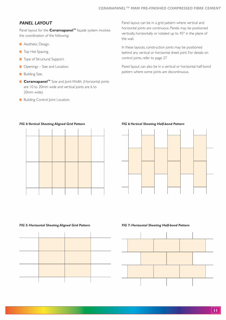
PANEL LAYOUT
Panel layout for the Ceramapanel™ façade system involves the coordination of the following:
Aesthetic Design.
Top Hat Spacing.
Type of Structural Support.
Ceramapanel™ Size and Joint Width. (Horizontal joints are 10 to 20mm wide and vertical joints are 6 to 20mm wide).
FIG 4: Vertical Sheeting Aligned Grid Pattern
FIG 5: Horizontal Sheeting Aligned Grid Pattern
FIG 6: Vertical Sheeting Half-bond Pattern
FIG 7: Horizontal Sheeting Half-bond Pattern
Panel layout can be in a grid pattern where vertical and horizontal joints are continuous. Panels may be positioned vertically, horizontally or rotated up to 45º in the plane of the wall.
In these layouts, construction joints may be positioned behind any vertical or horizontal sheet joint. For details on control joints, refer to page 27
Panel layout can also be in a vertical or horizontal half-bond pattern where some joints are discontinuous.
12
CERAMAPANEL™ 9MM PRE-FINISHED COMPRESSED FIBRE CEMENT
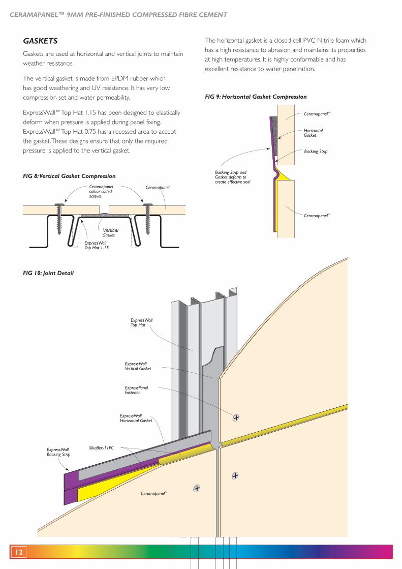
GASKETS
Gaskets are used at horizontal and vertical joints to maintain weather resistance.
The vertical gasket is made from EPDM rubber which has good weathering and UV resistance. It has very low compression set and water permeability.
ExpressWall™ Top Hat 1.15 has been designed to elastically deform when pressure is applied during panel fixing. ExpressWall™ Top Hat 0.75 has a recessed area to accept the gasket. These designs ensure that only the required pressure is applied to the vertical gasket.
The horizontal gasket is a closed cell PVC Nitrile foam which has a high resistance to abrasion and maintains its properties at high temperatures. It is highly conformable and has excellent resistance to water penetration.
ExpressWall Backing Strip
ExpressWall Horizontal Gasket
ExpressWall Vertical Gasket
Sikaflex-11FC
ExpressWall Top Hat
ExpressPanel Fastener
Ceramapanel™
FIG 10: Joint Detail
FIG 8: Vertical Gasket Compression
Horizontal Gasket
Backing Strip
Ceramapanel™
Ceramapanel™
Backing Strip and Gasket deform to create effective seal
FIG 9: Horizontal Gasket Compression
ExpressWall Top Hat 1.15
Vertical Gasket
Ceramapanel colour coded screws
Ceramapanel
CERAMAPANEL™ 9MM PRE-FINISHED COMPRESSED FIBRE CEMENT
13
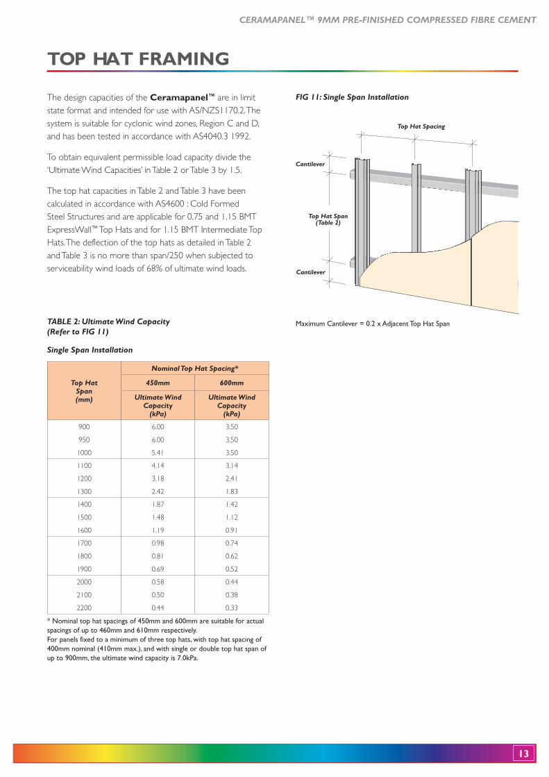
Top Hat Spacing
Top Hat Span (Table 2)
Cantilever
Cantilever
FIG 11: Single Span Installation
Maximum Cantilever = 0.2 x Adjacent Top Hat Span
The design capacities of the Ceramapanel™ are in limit state format and intended for use with AS/NZS1170.2. The system is suitable for cyclonic wind zones, Region C and D, and has been tested in accordance with AS4040.3 1992.
To obtain equivalent permissible load capacity divide the ‘Ultimate Wind Capacities’ in Table 2 or Table 3 by 1.5.
The top hat capacities in Table 2 and Table 3 have been calculated in accordance with AS4600 : Cold Formed
ExpressWall™
Hats. The deflection of the top hats as detailed in Table 2 and Table 3 is no more than span/250 when subjected to serviceability wind loads of 68% of ultimate wind loads.
TABLE 2: Ultimate Wind Capacity (Refer to FIG 11)
Single Span Installation
Top HatSpan(mm)
Nominal Top Hat Spacing*
450mm 600mm
Ultimate Wind Capacity
(kPa)
Ultimate Wind Capacity
(kPa)
900
950
1000
6.00
6.00
5.41
3.50
3.50
3.50
1100
1200
1300
4.14
3.18
2.42
3.14
2.41
1.83
1400
1500
1600
1.87
1.48
1.19
1.42
1.12
0.91
1700
1800
1900
0.98
0.81
0.69
0.74
0.62
0.52
2000
2100
2200
0.58
0.50
0.44
0.44
0.38
0.33
* Nominal top hat spacings of 450mm and 600mm are suitable for actual spacings of up to 460mm and 610mm respectively.For panels fixed to a minimum of three top hats, with top hat spacing of 400mm nominal (410mm max.), and with single or double top hat span of up to 900mm, the ultimate wind capacity is 7.0kPa.
14
CERAMAPANEL™ 9MM PRE-FINISHED COMPRESSED FIBRE CEMENT
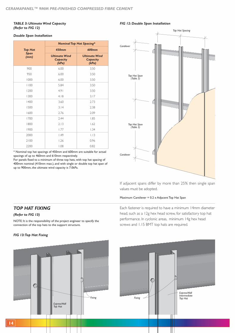
Cantilever
Cantilever
Top Hat Spacing
Top Hat Span (Table 3)
Top Hat Span (Table 3)
FIG 12: Double Span Installation
If adjacent spans differ by more than 25% then single span values must be adopted.
Maximum Cantilever = 0.2 x Adjacent Top Hat Span
Fixing
ExpressWallIntermediate Top HatFixing
ExpressWall Top Hat
FIG 13: Top Hat Fixing
TOP HAT FIXING(Refer to FIG 13)
NOTE: It is the responsibility of the project engineer to specify the connection of the top hats to the support structure.
Each fastener is required to have a minimum 14mm diameter head, such as a 12g hex head screw, for satisfactory top hat performance. In cyclonic areas, minimum 14g hex head
TABLE 3: Ultimate Wind Capacity (Refer to FIG 12)
Double Span Installation
Top HatSpan(mm)
Nominal Top Hat Spacing*
450mm 600mm
Ultimate Wind Capacity
(kPa)
Ultimate Wind Capacity
(kPa)
900
950
1000
6.00
6.00
6.00
3.50
3.50
3.50
1100
1200
1300
5.84
4.91
4.18
3.50
3.50
3.17
1400
1500
1600
3.60
3.14
2.76
2.73
2.38
2.09
1700
1800
1900
2.44
2.13
1.77
1.85
1.62
1.34
2000
2100
2200
1.49
1.26
1.08
1.13
0.96
0.82
* Nominal top hat spacings of 450mm and 600mm are suitable for actual spacings of up to 460mm and 610mm respectively.For panels fixed to a minimum of three top hats, with top hat spacing of 400mm nominal (410mm max.), and with single or double top hat span of up to 900mm, the ultimate wind capacity is 7.0kPa.
CERAMAPANEL™ 9MM PRE-FINISHED COMPRESSED FIBRE CEMENT
15
Ceramapanel™ preparation is a two step process.
– Affix backing strips and allow adhesive to set.
– Affix horizontal gasket to backing strips.
These steps may be performed off-site prior to installation.
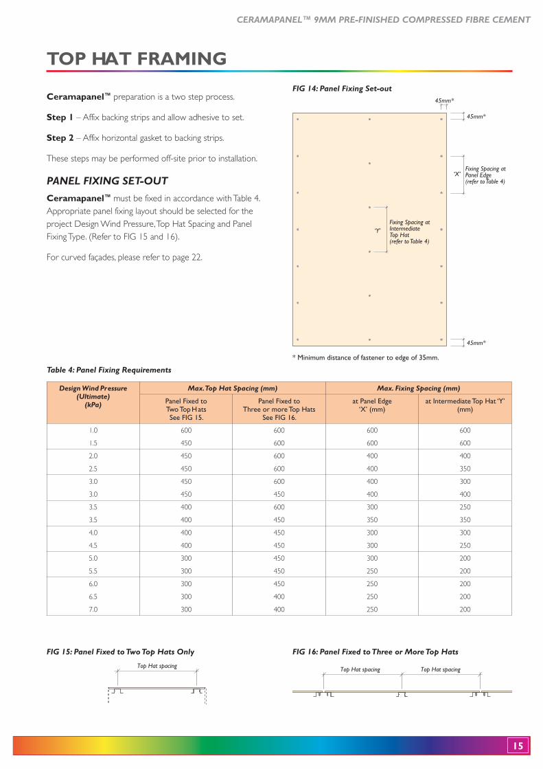
PANEL FIXING SET-OUT
Ceramapanel™ must be fixed in accordance with Table 4. Appropriate panel fixing layout should be selected for the project Design Wind Pressure, Top Hat Spacing and Panel Fixing Type. (Refer to FIG 15 and 16).
For curved façades, please refer to page 22.
45mm*
45mm*
45mm*
Fixing Spacing at Panel Edge (refer to Table 4)
Fixing Spacing at Intermediate Top Hat(refer to Table 4)
‘X’
‘Y’
FIG 14: Panel Fixing Set-out
* Minimum distance of fastener to edge of 35mm.
Top Hat spacing Top Hat spacing
FIG 16: Panel Fixed to Three or More Top Hats
Top Hat spacing
FIG 15: Panel Fixed to Two Top Hats Only
Table 4: Panel Fixing Requirements
Design Wind Pressure (Ultimate)
(kPa)
Max. Top Hat Spacing (mm) Max. Fixing Spacing (mm)
Panel Fixed to Two Top Hats See FIG 15.
Panel Fixed to Three or more Top Hats
See FIG 16.
at Panel Edge‘X’ (mm)
at Intermediate Top Hat ‘Y’ (mm)
1.0
1.5
600
450
600
600
600
600
600
600
2.0
2.5
450
450
600
600
400
400
400
350
3.0
3.0
450
450
600
450
400
400
300
400
3.5
3.5
400
400
600
450
300
350
250
350
4.0
4.5
400
400
450
450
300
300
300
250
5.0
5.5
300
300
450
450
300
250
200
200
6.0
6.5
7.0
300
300
300
450
400
400
250
250
250
200
200
200
16
CERAMAPANEL™ 9MM PRE-FINISHED COMPRESSED FIBRE CEMENT
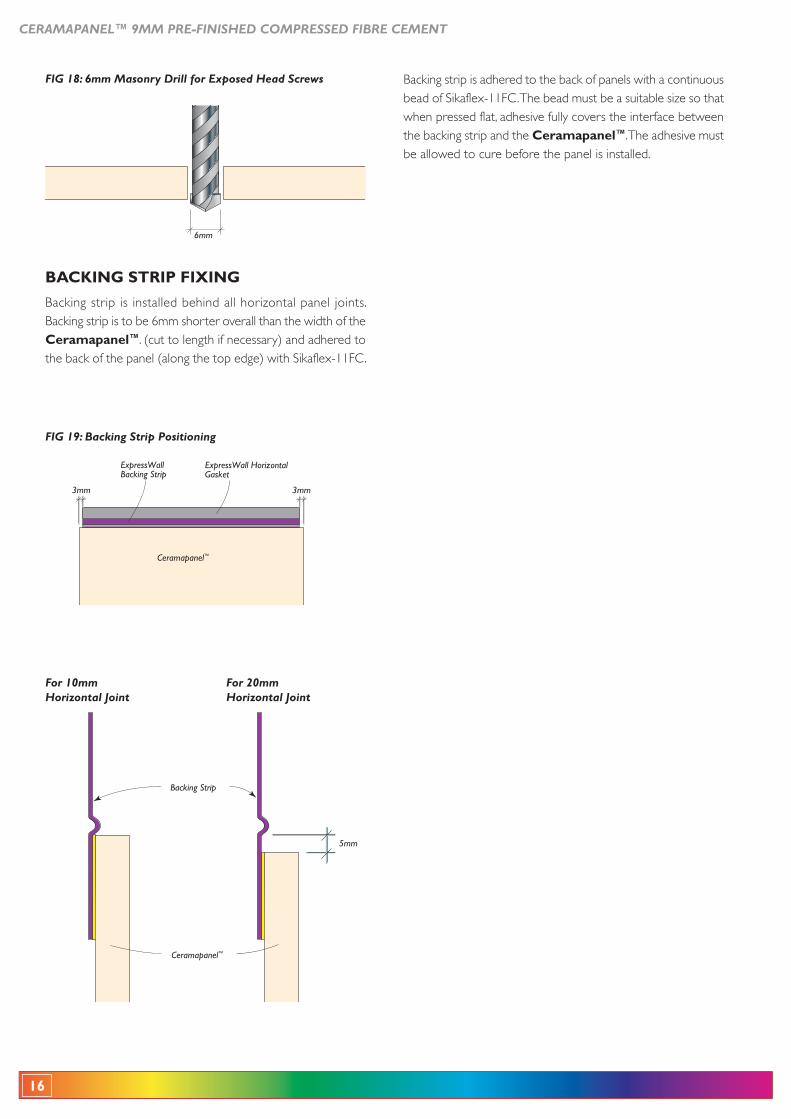
ExpressWall Backing Strip
ExpressWall Horizontal Gasket
3mm 3mm
Ceramapanel™
FIG 19: Backing Strip Positioning
5mm
Ceramapanel™
Backing Strip
For 10mm Horizontal Joint
For 20mm Horizontal Joint
FIG 18: 6mm Masonry Drill for Exposed Head Screws
6mm
Ceramapanel™. (cut to length if necessary) and adhered to the back of the panel (along the top edge) with Sikaflex-11FC.
bead of Sikaflex-11FC. The bead must be a suitable size so that when pressed flat, adhesive fully covers the interface between the backing strip and the Ceramapanel™. The adhesive must be allowed to cure before the panel is installed.
CERAMAPANEL™ 9MM PRE-FINISHED COMPRESSED FIBRE CEMENT
17
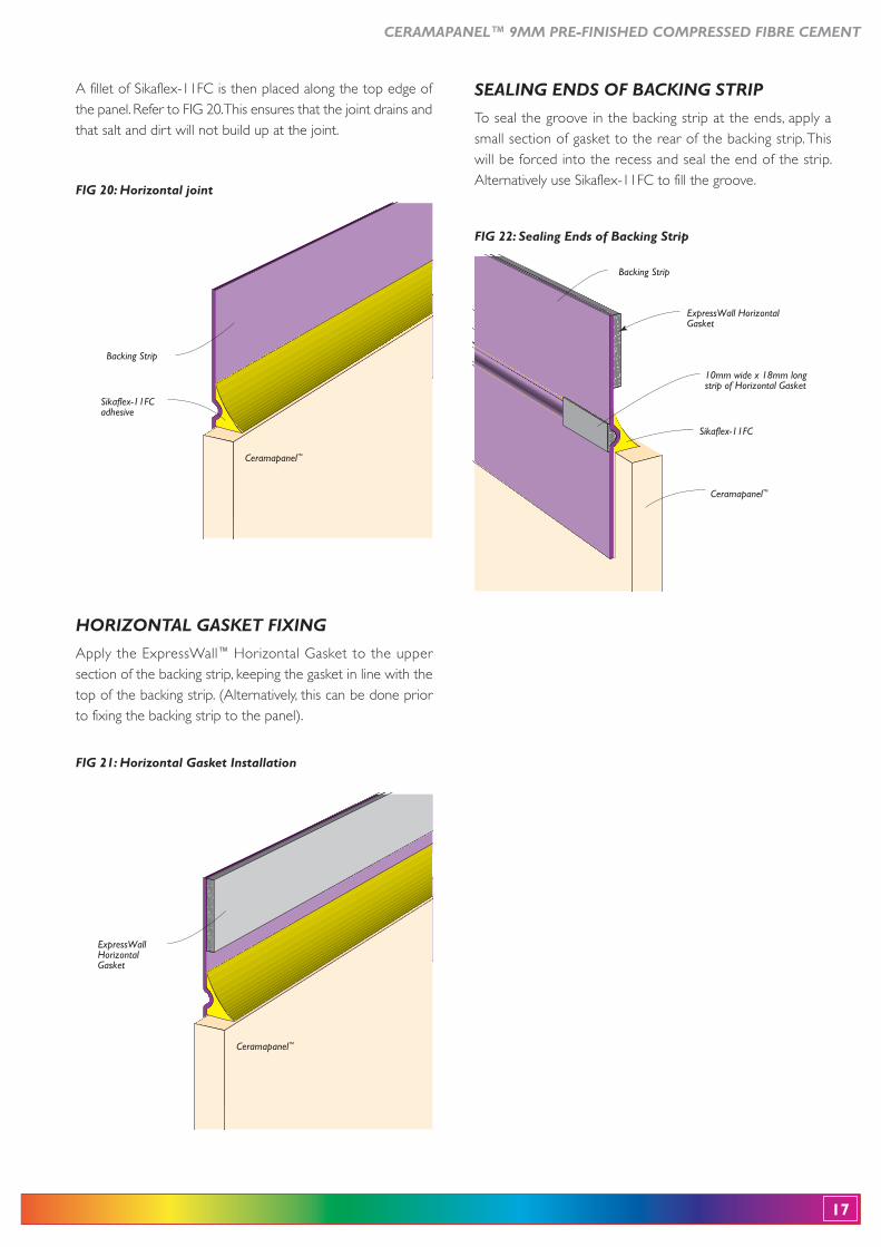
HORIZONTAL GASKET FIXING
Apply the ExpressWall™ Horizontal Gasket to the upper section of the backing strip, keeping the gasket in line with the top of the backing strip. (Alternatively, this can be done prior to fixing the backing strip to the panel).
ExpressWall Horizontal Gasket
10mm wide x 18mm long strip of Horizontal Gasket
Ceramapanel™
Sikaflex-11FC
Backing Strip
FIG 22: Sealing Ends of Backing Strip
Ceramapanel™
Sikaflex-11FCadhesive
Backing Strip
FIG 20: Horizontal joint
Ceramapanel™
ExpressWall Horizontal Gasket
FIG 21: Horizontal Gasket Installation
SEALING ENDS OF BACKING STRIP
To seal the groove in the backing strip at the ends, apply a small section of gasket to the rear of the backing strip. This will be forced into the recess and seal the end of the strip. Alternatively use Sikaflex-11FC to fill the groove.
A fillet of Sikaflex-11FC is then placed along the top edge of the panel. Refer to FIG 20. This ensures that the joint drains and that salt and dirt will not build up at the joint.
18
CERAMAPANEL™ 9MM PRE-FINISHED COMPRESSED FIBRE CEMENT
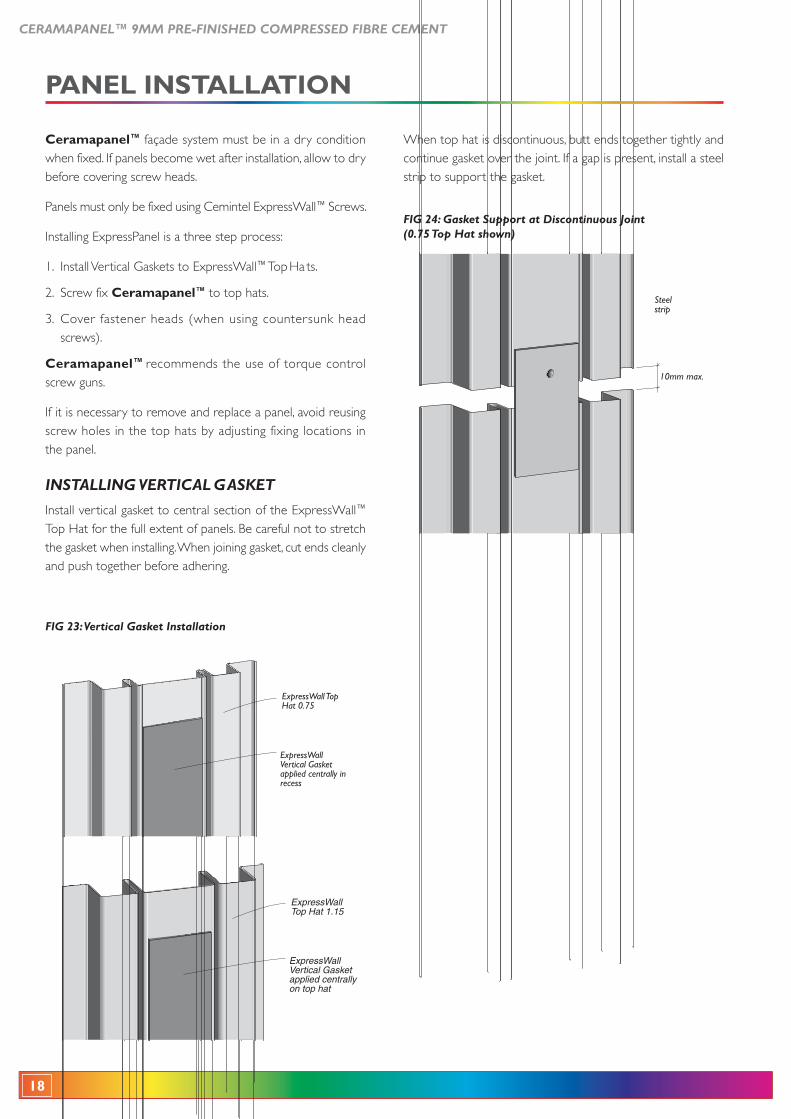
When top hat is discontinuous, butt ends together tightly and continue gasket over the joint. If a gap is present, install a steel strip to support the gasket.
Steelstrip
10mm max.
FIG 24: Gasket Support at Discontinuous Joint (0.75 Top Hat shown)
Ceramapanel™ façade system must be in a dry condition when fixed. If panels become wet after installation, allow to dry before covering screw heads.
Panels must only be fixed using Cemintel ExpressWall™ Screws.
Installing ExpressPanel is a three step process:
1. Install Vertical Gaskets to ExpressWall™ Top Ha ts.
2. Screw fix Ceramapanel™ to top hats.
3. Cover fastener heads (when using countersunk head screws).
Ceramapanel™ recommends the use of torque control screw guns.
If it is necessary to remove and replace a panel, avoid reusing screw holes in the top hats by adjusting fixing locations in the panel.
INSTALLING VERTICAL GASKET
Install vertical gasket to central section of the ExpressWall™
the gasket when installing. When joining gasket, cut ends cleanly and push together before adhering.
ExpressWall Top Hat 1.15
ExpressWall Vertical Gasket applied centrally on top hat
FIG 23: Vertical Gasket Installation
ExpressWall Top Hat 0.75
ExpressWall Vertical Gasket applied centrally in recess
PANEL INSTALLATION
CERAMAPANEL™ 9MM PRE-FINISHED COMPRESSED FIBRE CEMENT
19
Exposed Head Screw
ExpressWall™ Top Hat 1.15
Weather Seal compressed in
hole and compressed around screw thread
FIG 26: Fixing with Exposed Head Screws
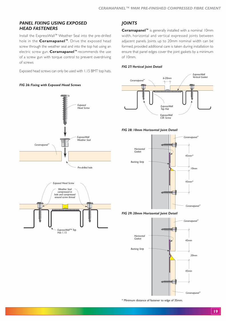
PANEL FIXING USING EXPOSED HEAD FASTENERS
Install the ExpressWall™ Weather Seal into the pre-drilled hole in the Ceramapanel™. Drive the exposed head screw through the weather seal and into the top hat using an electric screw gun. Ceramapanel™ recommends the use of a screw gun with torque control to prevent overdriving of screws
ExposedHead Screw
ExpressWallWeather Seal
Ceramapanel™
Pre-drilled hole
Ceramapanel™
ExpressWall Vertical Gasket6-20mm
ExpressWall Top Hat
ExpressWall CSK Screw
FIG 27: Vertical Joint Detail
FIG 28: 10mm Horizontal Joint Detail
Horizontal Gasket
Backing Strip
Ceramapanel™
Ceramapanel™
45mm*
45mm*
10mm
JOINTS
Ceramapanel™ is generally installed with a nominal 10mm width, horizontal and ver tical expressed joints between adjacent panels. Joints up to 20mm nominal width can be formed, provided additional care is taken during installation to ensure that panel edges cover the joint gaskets by a minimum of 10mm.
Horizontal Gasket
Backing Strip
Ceramapanel™
Ceramapanel™
45mm
45mm
20mm
FIG 29: 20mm Horizontal Joint Detail
* Minimum distance of fastener to edge of 35mm.
20
CERAMAPANEL™ 9MM PRE-FINISHED COMPRESSED FIBRE CEMENT
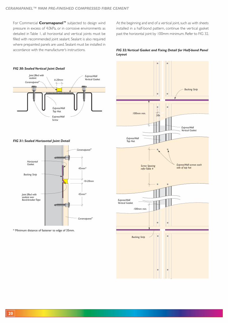
FIG 32: Vertical Gasket and Fixing Detail for Half-bond Panel Layout
At the beginning and end of a vertical joint, such as with sheets installed in a half-bond pattern, continue the vertical gasket past the horizontal joint by 100mm minimum. Refer to FIG 32.
ExpressWallVertical Gasket
ExpressWall screws each side of top hat
ExpressWallTop Hat
100mm min.
50mm
Backing Strip
100mm min.
ExpressWallVertical Gasket
Backing Strip
Screw Spacing refer Table 4
For Commercial Ceramapanel™ subjected to design wind pressure in excess of 4.0kPa, or in corrosive environments as detailed in Table 1, all horizontal and vertical joints must be filled with recommended joint sealant. Sealant is also required where prepainted panels are used. Sealant must be installed in accordance with the manufacturer’s instructions.
Joint filled with sealant
ExpressWallTop Hat
Ceramapanel™
ExpressWallVertical Gasket6-20mm
ExpressWallScrew
FIG 30: Sealed Vertical Joint Detail
FIG 31: Sealed Horizontal Joint Detail
Horizontal Gasket
Backing Strip
Ceramapanel™
Ceramapanel™
45mm*
45mm*
10-20mm
Joint filled with sealant over Bond-breaker Tape
* Minimum distance of fastener to edge of 35mm.
CERAMAPANEL™ 9MM PRE-FINISHED COMPRESSED FIBRE CEMENT
21
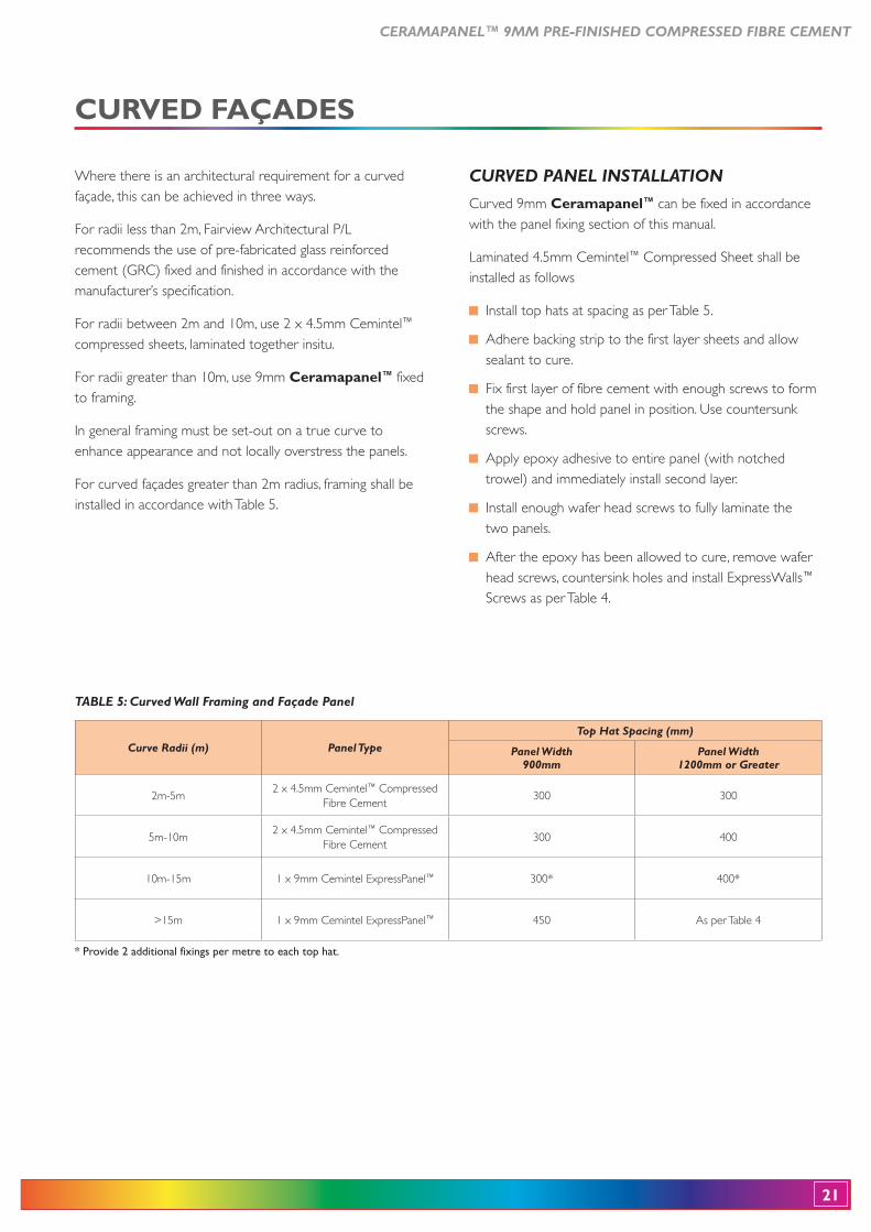
Where there is an architectural requirement for a curved façade, this can be achieved in three ways.
For radii less than 2m, Fairview Architectural P/L recommends the use of pre-fabricated glass reinforced cement (GRC) fixed and finished in accordance with the manufacturer’s specification.
For radii between 2m and 10m, use 2 x 4.5mm Cemintel™ compressed sheets, laminated together insitu.
For radii greater than 10m, use 9mm Ceramapanel™ fixed to framing.
In general framing must be set-out on a true curve to enhance appearance and not locally overstress the panels.
For curved façades greater than 2m radius, framing shall be installed in accordance with Table 5.
CURVED PANEL INSTALLATION
Curved 9mm Ceramapanel™ can be fixed in accordance with the panel fixing section of this manual.
Laminated 4.5mm Cemintel™ Compressed Sheet shall be installed as follows
Install top hats at spacing as per Table 5.
Adhere backing strip to the first layer sheets and allow sealant to cure.
Fix first layer of fibre cement with enough screws to form the shape and hold panel in position. Use countersunk screws.
Apply epoxy adhesive to entire panel (with notched trowel) and immediately install second layer.
Install enough wafer head screws to fully laminate the two panels.
After the epoxy has been allowed to cure, remove wafer head screws, countersink holes and install ExpressWalls™ Screws as per Table 4.
TABLE 5: Curved Wall Framing and Façade Panel
Curve Radii (m) Panel TypeTop Hat Spacing (mm)
Panel Width 900mm
Panel Width 1200mm or Greater
2m-5m2 x 4.5mm Cemintel™ Compressed
Fibre Cement300 300
5m-10m2 x 4.5mm Cemintel™ Compressed
Fibre Cement300 400
10m-15m 1 x 9mm Cemintel ExpressPanel™ 300* 400*
>15m 1 x 9mm Cemintel ExpressPanel™ 450 As per Table 4
* Provide 2 additional fixings per metre to each top hat.
22
CERAMAPANEL™ 9MM PRE-FINISHED COMPRESSED FIBRE CEMENT
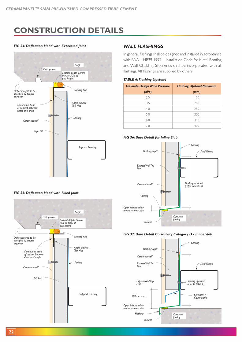
FIG 34: Deflection Head with Expressed Joint
Angle fixed to Top Hat
Sarking
Drip grooveSoffit
Backing Rod
Ceramapanel™
Top Hat
Deflection gap to be specified by project engineer
Support Framing
Continuous bead of sealant between sheet and angle
Sealant depth 12mm min. or 50% of gap height
FIG 36: Base Detail for Inline Slab
Concrete footing
Sealant
Sarking
Flashing
Flashing Tape
Ceramapanel™
Open joint to allow moisture to escape
Flashing upstand (refer to Table 6)
ExpressWall Top Hat
Steel Frame
FIG 35: Deflection Head with Filled Joint
Angle fixed to Top Hat
Drip groove
Soffit
Backing Rod
Ceramapanel™
Top Hat
Deflection gap to be specified by project engineer
Support Framing
Continuous bead of sealant between sheet and angle
Sarking
Sealant depth 12mm min. or 50% of gap height
CONSTRUCTION DETAILS
WALL FLASHINGS
In general, flashings shall be designed and installed in accordance
and Wall Cladding. Stop ends shall be incorporated with all flashings. All flashings are supplied by others.
Ultimate Design Wind Pressure Flashing Upstand Minimum
(kPa) (mm)
2.5 150
3.5 200
4.0 250
5.0 300
6.0 350
7.0 400
TABLE 6: Flashing Upstand
FIG 37: Base Detail Corrosivity Category D - Inline Slab
Concrete footing
Sealant
Sarking
Flashing
Flashing Tape
Ceramapanel™
100mm max.
Open joint to allow moisture to escape
Flashing upstand (refer to Table 6)
ExpressWall Top Hat
Cemintel™ Cavity Baffle
ExpressWall Top Hat
Steel Frame
CERAMAPANEL™ 9MM PRE-FINISHED COMPRESSED FIBRE CEMENT
23
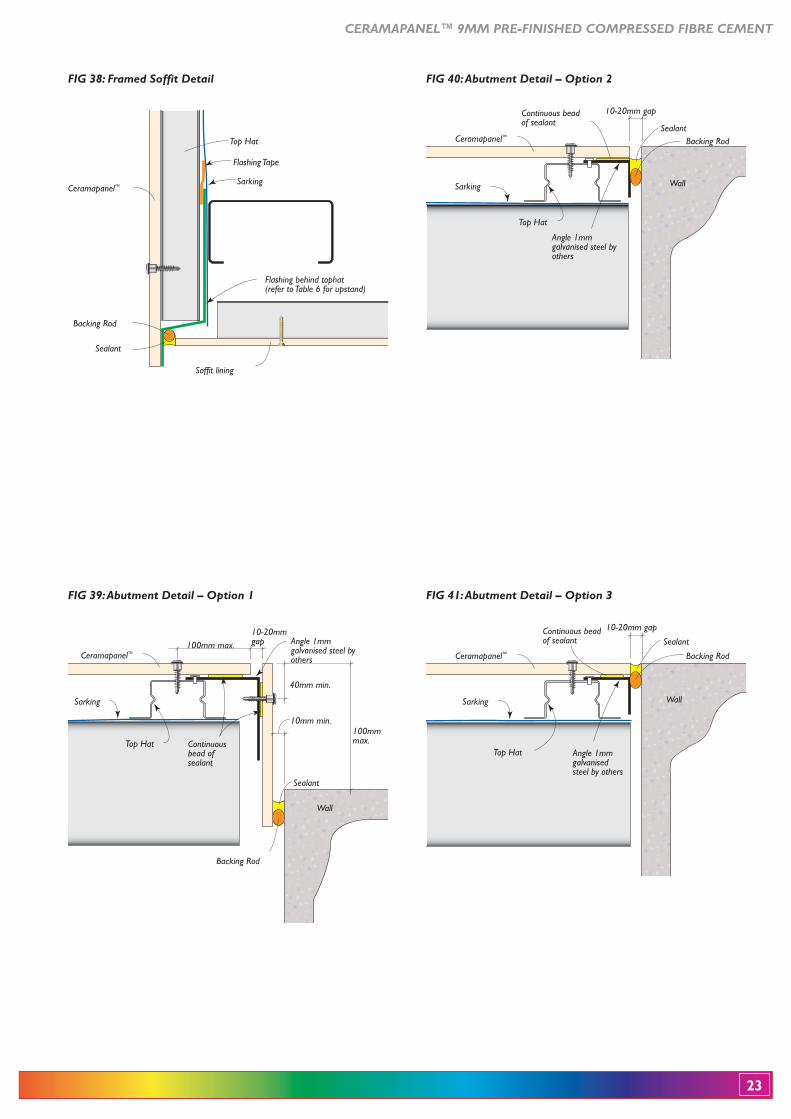
FIG 39: Abutment Detail – Option 1
Sarking
10mm min.
Sealant
Wall
100mm max.
40mm min.
Backing Rod
Ceramapanel™
Top Hat Continuous bead of sealant
Angle 1mm galvanised steel by others
100mmmax.
10-20mm gap
FIG 40: Abutment Detail – Option 2
Top Hat
Angle 1mm galvanised steel by others
Sealant
Wall
Backing RodCeramapanel™
Continuous bead of sealant
Sarking
10-20mm gap
FIG 41: Abutment Detail – Option 3
Sealant
Wall
Backing RodCeramapanel™
Sarking
Continuous bead of sealant
10-20mm gap
Top Hat Angle 1mm galvanised steel by others
FIG 38: Framed Soffit Detail
Ceramapanel™
Top Hat
Flashing behind tophat(refer to Table 6 for upstand)
Soffit lining
Backing Rod
Sealant
Sarking
Flashing Tape
24
CERAMAPANEL™ 9MM PRE-FINISHED COMPRESSED FIBRE CEMENT
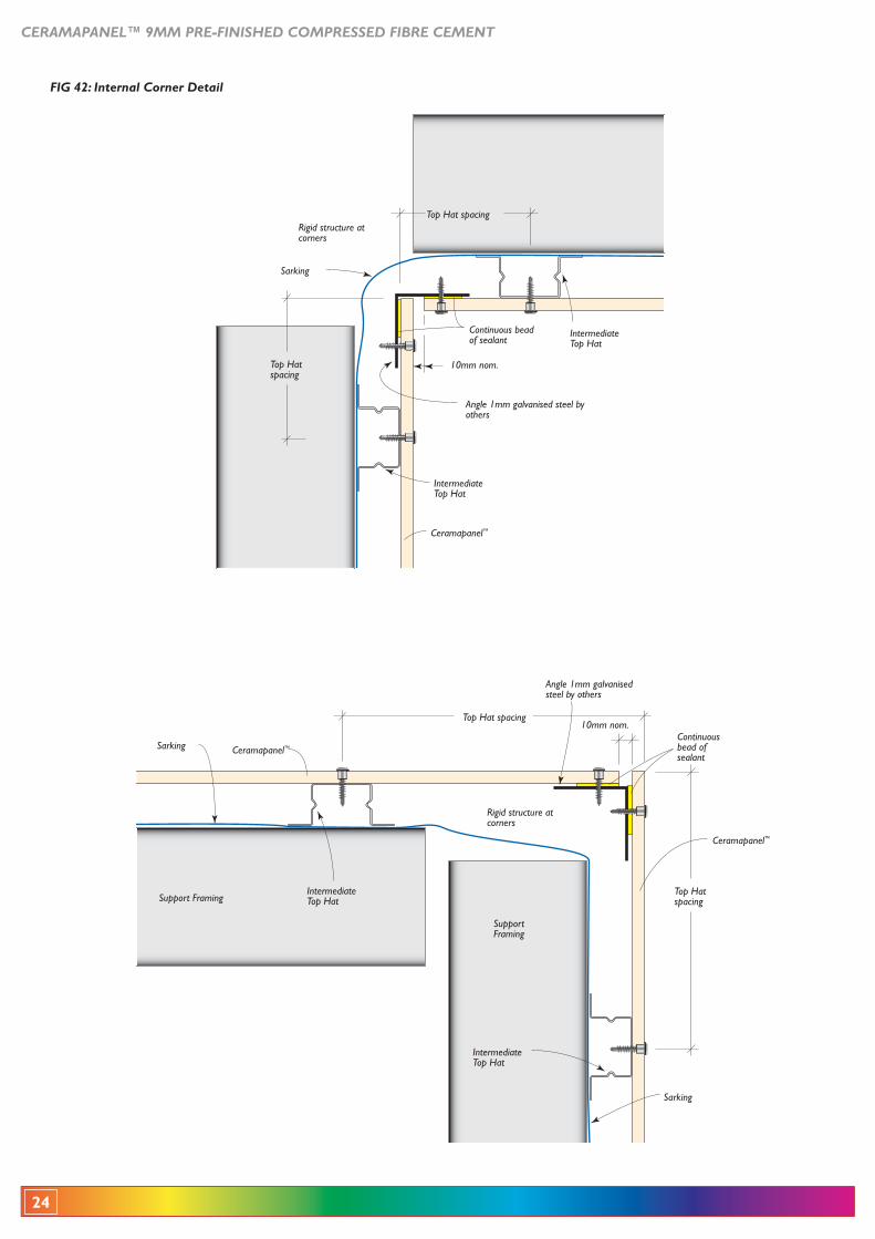
FIG 42: Internal Corner Detail
Intermediate Top Hat
Rigid structure at corners
Intermediate Top Hat
Ceramapanel™
Angle 1mm galvanised steel by others
Continuous bead of sealant
Top Hat spacing
Top Hat spacing
Sarking
10mm nom.
Rigid structure at corners
Intermediate Top Hat
Intermediate Top Hat
Ceramapanel™
Ceramapanel™
Sarking
SarkingContinuous bead of sealant
Top Hat spacing
Top Hat spacingSupport Framing
Support Framing
Angle 1mm galvanised steel by others
10mm nom.
CERAMAPANEL™ 9MM PRE-FINISHED COMPRESSED FIBRE CEMENT
25
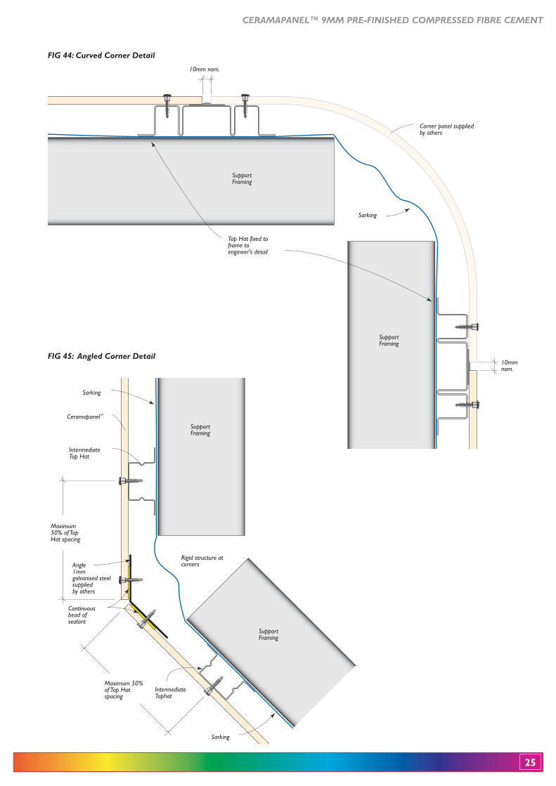
FIG 44: Curved Corner Detail
Top Hat fixed to frame to engineer's detail
Support Framing
Support Framing
Sarking
10mm nom.
10mm nom.
Corner panel supplied by others
Intermediate Top Hat
Ceramapanel™
Continuous bead of sealant
Sarking
Maximum 50% of Top Hat spacing
Rigid structure at corners
Sarking
Support Framing
Support Framing
Intermediate Tophat
Maximum 50% of Top Hat spacing
Angle 1mm galvanised steel supplied by others
FIG 45: Angled Corner Detail
26
CERAMAPANEL™ 9MM PRE-FINISHED COMPRESSED FIBRE CEMENT
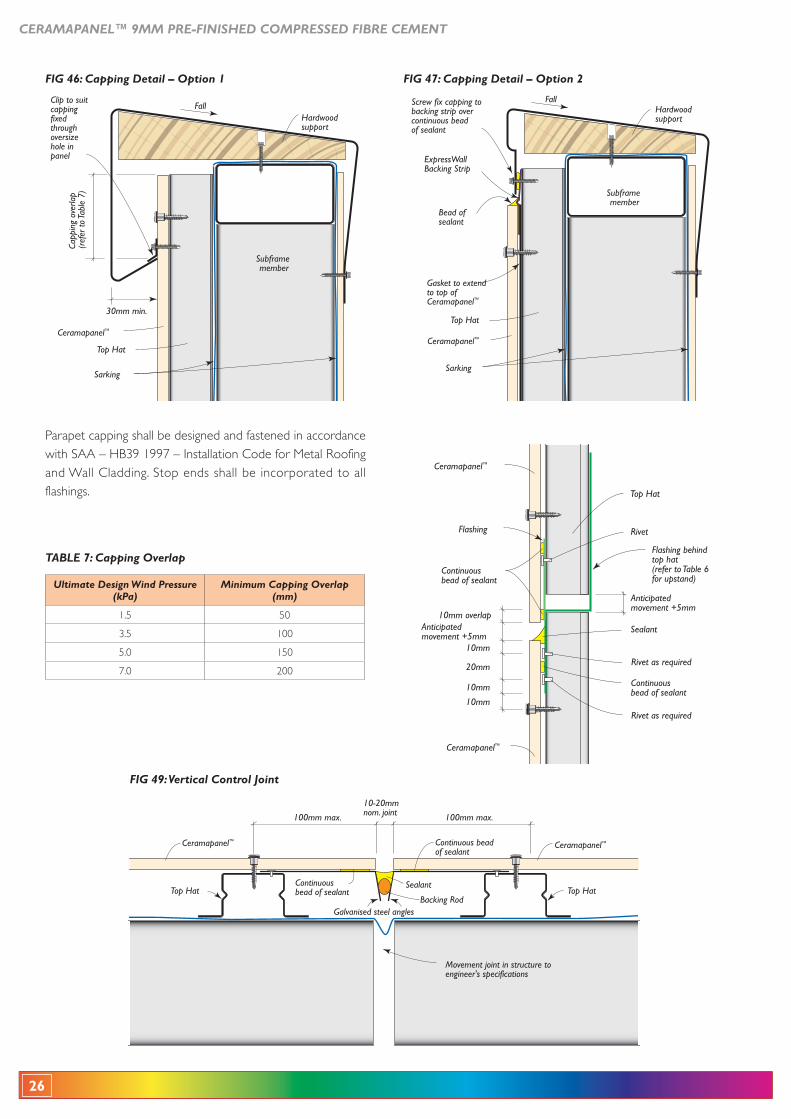
FIG 49: Vertical Control Joint
Movement joint in structure to engineer's specifications
100mm max. 100mm max.
10-20mmnom. joint
Continuous beadof sealant
SealantTop Hat Top Hat
Continuousbead of sealant
Galvanised steel anglesBacking Rod
Ceramapanel™Ceramapanel™
FIG 46: Capping Detail – Option 1
Ceramapanel™
Capp
ing
over
lap
(ref
er to
Tabl
e 7)
Sarking
30mm min.
Fall
Subframe member
Hardwood support
Top Hat
Clip to suit capping fixed through oversize hole in panel
FIG 47: Capping Detail – Option 2
Ceramapanel™
Sarking
Fall
Bead of sealant
ExpressWallBacking Strip
Subframe member
Hardwood support
Top Hat
Gasket to extend to top of Ceramapanel™
Screw fix capping to backing strip over continuous bead of sealant
Ceramapanel™
Flashing
Top Hat
Sealant
Rivet as required
Rivet as required
Rivet
10mm
10mm overlapAnticipatedmovement +5mm
Anticipatedmovement +5mm
10mm
10mm
20mm
Ceramapanel™
Continuousbead of sealant
Continuousbead of sealant
Flashing behind top hat(refer to Table 6 for upstand)
Parapet capping shall be designed and fastened in accordance
and Wall Cladding. Stop ends shall be incorporated to all flashings.
TABLE 7: Capping Overlap
Ultimate Design Wind Pressure(kPa)
Minimum Capping Overlap (mm)
1.5 50
3.5 100
5.0 150
7.0 200
CERAMAPANEL™ 9MM PRE-FINISHED COMPRESSED FIBRE CEMENT
27
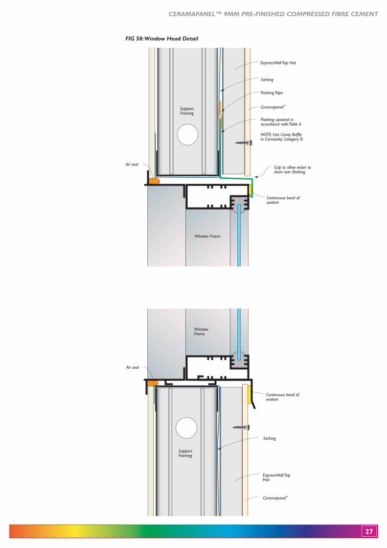
FIG 50: Window Head Detail
Flashing upstand in accordance with Table 6
NOTE: Use Cavity Baffle in Corrosivity Category D
Flashing Tape
Ceramapanel™
Gap to allow water to drain over flashing
Continuous bead of sealant
Sarking
Air seal
ExpressWall Top Hat
Window Frame
Support Framing
Support Framing
Window Frame
ExpressWall Top Hat
Ceramapanel™
Continuous bead of sealant
Sarking
Air seal
28
CERAMAPANEL™ 9MM PRE-FINISHED COMPRESSED FIBRE CEMENT
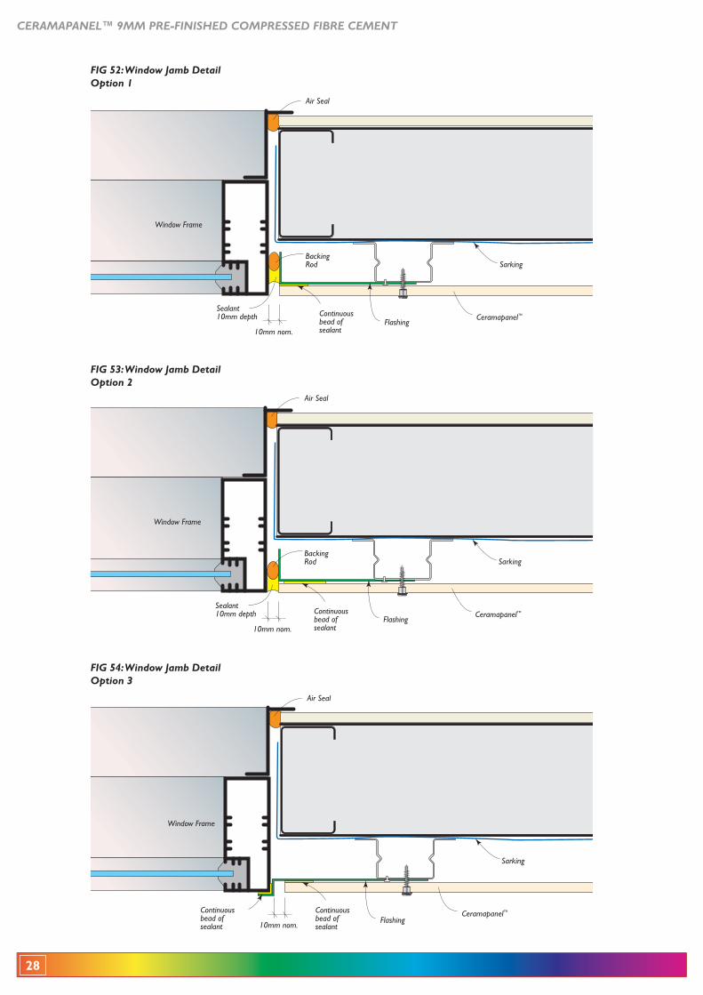
FIG 53: Window Jamb Detail Option 2
Continuous bead of sealant10mm nom.
Ceramapanel™Sealant 10mm depth
Flashing
SarkingBacking Rod
Air Seal
Window Frame
FIG 54: Window Jamb Detail Option 3
Ceramapanel™
Sarking
Continuous bead of sealant
Flashing10mm nom.
Air Seal
Window Frame
Continuous bead of sealant
FIG 52: Window Jamb Detail Option 1
10mm nom.
Ceramapanel™Continuous bead of sealant
Sealant 10mm depth
Flashing
SarkingBacking Rod
Air Seal
Window Frame
CERAMAPANEL™ 9MM PRE-FINISHED COMPRESSED FIBRE CEMENT
29
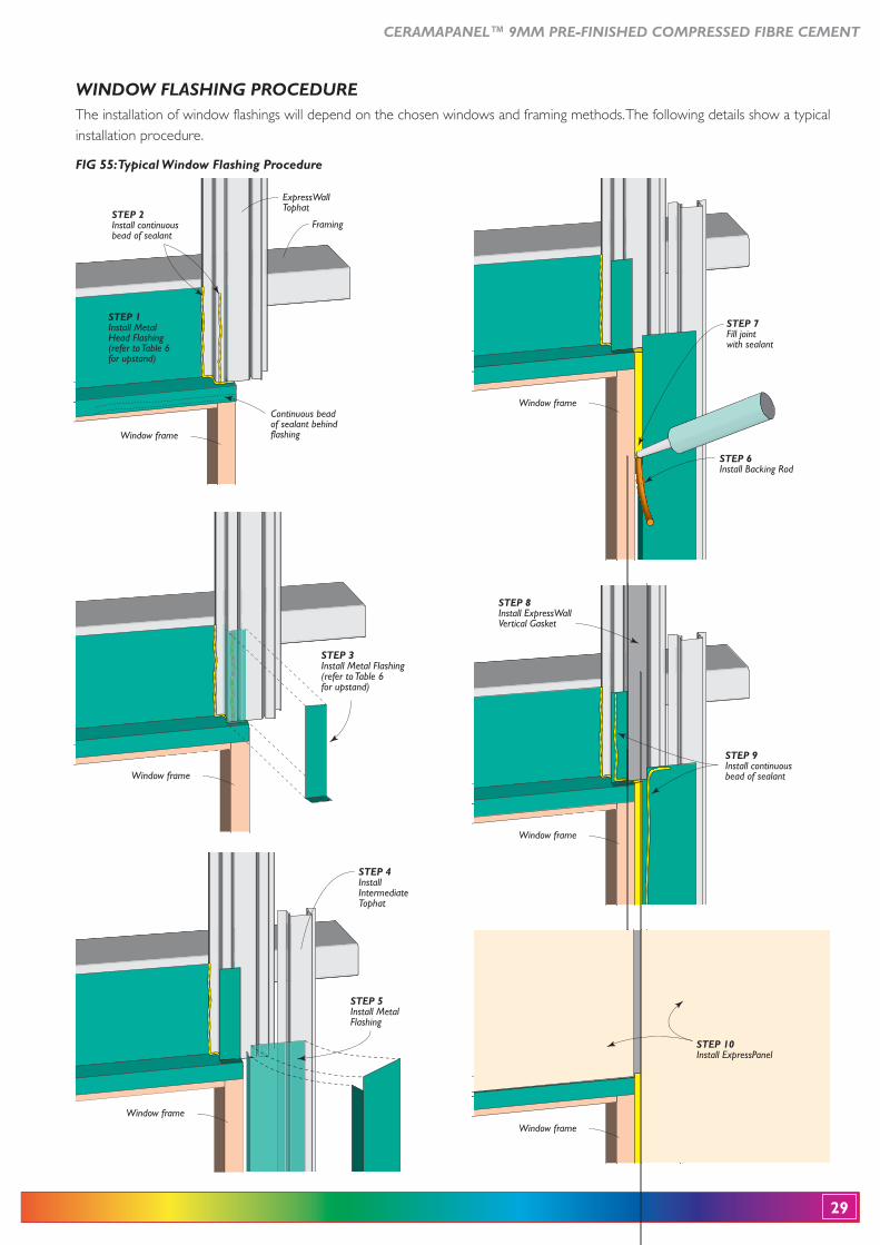
ExpressWallTophat
Framing
Window frame
STEP 1Install Metal Head Flashing(refer to Table 6for upstand)
STEP 2Install continuous bead of sealant
Continuous beadof sealant behindflashing
Window frame
STEP 7Fill joint with sealant
STEP 6Install Backing Rod
Window frame
STEP 9Install continuousbead of sealant
STEP 8Install ExpressWallVertical Gasket
STEP 10Install ExpressPanel
Window frame
WINDOW FLASHING PROCEDURE
Window frame
STEP 3Install Metal Flashing(refer to Table 6for upstand)
Window frame
STEP 5Install Metal Flashing
STEP 4Install Intermediate Tophat
The installation of window flashings will depend on the chosen windows and framing methods. The following details show a typical installation procedure.
FIG 55: Typical Window Flashing Procedure
30
CERAMAPANEL™ 9MM PRE-FINISHED COMPRESSED FIBRE CEMENT
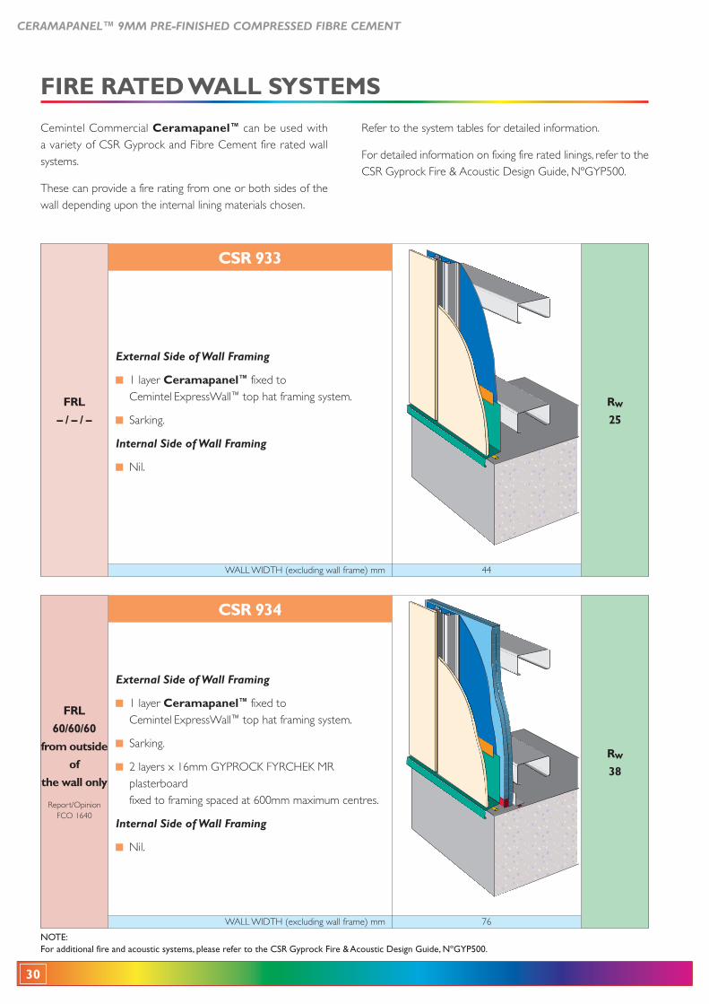
WALL WIDTH (excluding wall frame) mm 76
R
38
60/60/60
External Side of Wall Framing
1 layer Ceramapanel™ fixed to Cemintel ExpressWall™ top hat framing system.
Sarking.
plasterboard fixed to framing spaced at 600mm maximum centres.
Internal Side of Wall Framing
Nil.
CSR 934
WALL WIDTH (excluding wall frame) mm 44
R
25– / – / –
External Side of Wall Framing
1 layer Ceramapanel™ fixed to Cemintel ExpressWall™ top hat framing system.
Sarking.
Internal Side of Wall Framing
Nil.
CSR 933
NOTE:For additional fire and acoustic systems, please refer to the CSR Gyprock Fire & Acoustic Design Guide, NºGYP500.
Cemintel Commercial Ceramapanel™ can be used with a variety of CSR Gyprock and Fibre Cement fire rated wall systems.
These can provide a fire rating from one or both sides of the wall depending upon the internal lining materials chosen.
Refer to the system tables for detailed information.
For detailed information on fixing fire rated linings, refer to the CSR Gyprock Fire & Acoustic Design Guide, NºGYP500.
CERAMAPANEL™ 9MM PRE-FINISHED COMPRESSED FIBRE CEMENT
31
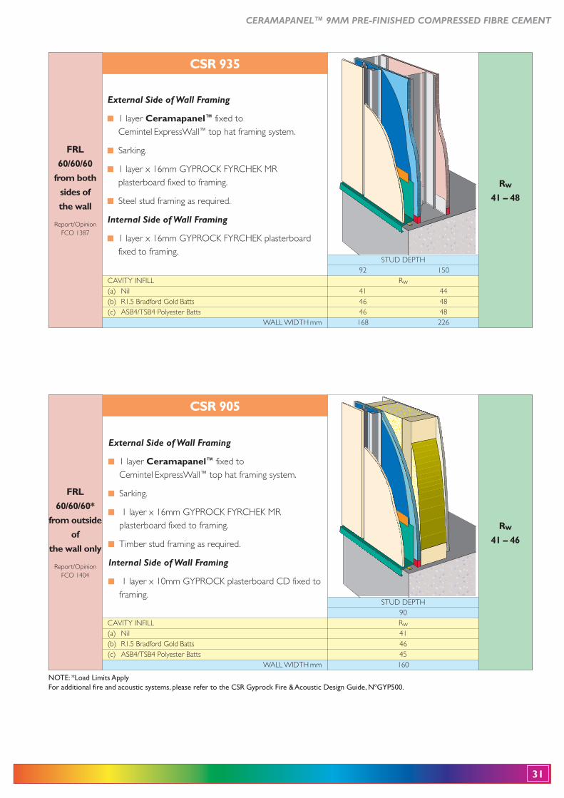
NOTE: *Load Limits ApplyFor additional fire and acoustic systems, please refer to the CSR Gyprock Fire & Acoustic Design Guide, NºGYP500.
60/60/60
STUD DEPTH 92 150CAVITY INFILL Rw(a) Nil 41 44
WALL WIDTH mm 168 226
CSR 935
External Side of Wall Framing
1 layer Ceramapanel™ fixed to Cemintel ExpressWall™ top hat framing system.
Sarking.
plasterboard fixed to framing.
Steel stud framing as required.
Internal Side of Wall Framing
fixed to framing.
R
41 – 48
60/60/60*
STUD DEPTH 90CAVITY INFILL Rw(a) Nil 41
WALL WIDTH mm 160
CSR 905
External Side of Wall Framing
1 layer Ceramapanel™ fixed to Cemintel ExpressWall™ top hat framing system.
Sarking.
plasterboard fixed to framing.
Timber stud framing as required.
Internal Side of Wall Framing
framing.
R
41 – 46
32
CERAMAPANEL™ 9MM PRE-FINISHED COMPRESSED FIBRE CEMENT
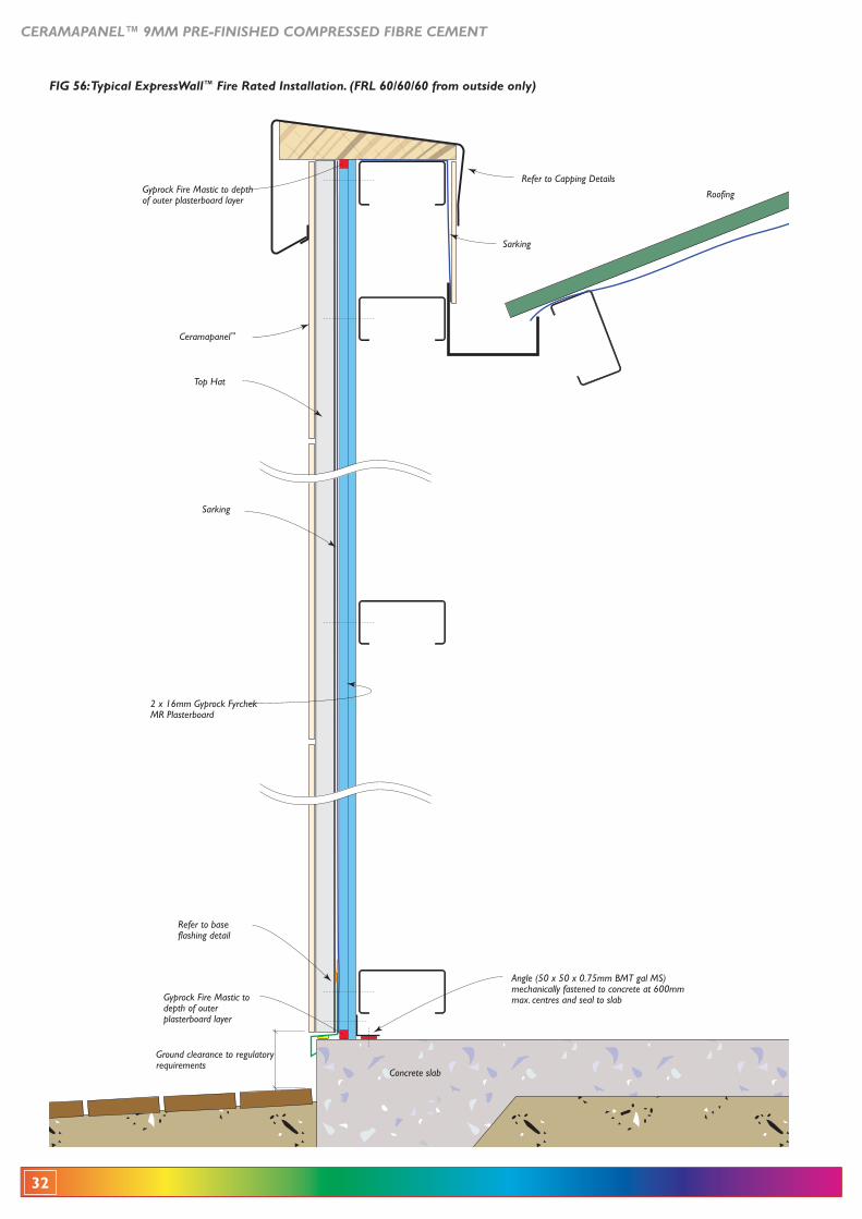
2 x 16mm Gyprock Fyrchek MR Plasterboard
Refer to Capping Details
Concrete slab
Ceramapanel™
Sarking
Ground clearance to regulatory requirements
Gyprock Fire Mastic to depth of outer plasterboard layer
Gyprock Fire Mastic to depth of outer plasterboard layer
Top Hat
Roofing
Angle (50 x 50 x 0.75mm BMT gal MS) mechanically fastened to concrete at 600mm max. centres and seal to slab
Refer to base flashing detail
Sarking
FIG 56: Typical ExpressWall™ Fire Rated Installation. (FRL 60/60/60 from outside only)
CERAMAPANEL™ 9MM PRE-FINISHED COMPRESSED FIBRE CEMENT
33
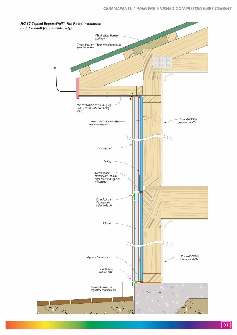
16mm GYPROCK FYRCHEK MR Plasterboard
Non-combustible eaves lining (eg. CSR Fibre Cement Eaves Lining Sheet)
CSR Bradford Fibertex Rockwool
Timber blocking (45mm min. thickness) to form fire barrier
10mm GYPROCK plasterboard CD
10mm GYPROCK plasterboard CD
Concrete slab
Ceramapanel™
Sarking
Top Hat
Control joint in Ceramapanel(refer to detail)
Control joint in plasterboard (15mm high) filled with Gyprock Fire Mastic
Ground clearance to regulatory requirements
Refer to base flashing detail
Gyprock Fire Mastic
FIG 57: Typical ExpressWall™ Fire Rated Installation(FRL 60/60/60 from outside only).
34
CERAMAPANEL™ 9MM PRE-FINISHED COMPRESSED FIBRE CEMENT
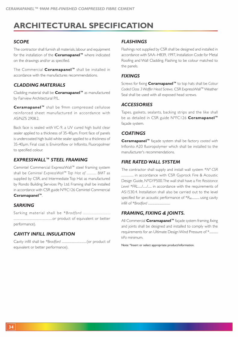
SCOPE
The contractor shall furnish all materials, labour and equipment for the installation of the Ceramapanel™ where indicated on the drawings and/or as specified.
The Commercial Ceramapanel™ shall be installed in accordance with the manufactures recommendations.
CLADDING MATERIALS
Cladding material shall be Ceramapanel™ as manufactured by Fairview Architectural P/L.
Ceramapanel™ shall be 9mm compressed cellulose reinforced sheet manufactured in accordance with AS/NZS 2908.2.
sealer applied to a thickness of 35-40μm. Front face of panels is undercoated high build white sealer applied to a thickness of 35-40μm. Final coat is Environflow or Inflonito, Fluoropolmer to specified colour.
EXPRESSWALL™ STEEL FRAMING
Cemintel Commercial ExpressWall™ steel framing system shall be Cemintel ExpressWall™ Top Hat of ............ BMT as supplied by CSR, and Intermediate Top Hat as manufactured
in accordance with CSR guide NºFC126 Cemintel Commercial Ceramapanel™.
SARKING
Sar k ing mater ia l sha l l be *Bradford . . . . . . . . . . . . . . . . . . . . . . . . . . ...................................................or product of equivalent or better performance).
CAVITY INFILL INSULATION
Cavity infill shall be *Bradford ...................................(or product of equivalent or better performance).
FLASHINGS
Flashings not supplied by CSR shall be designed and installed in
Roofing and Wall Cladding. Flashing to be colour matched to the panels.
FIXINGS
Screws for fixing Ceramapanel™ to top hats shall be Colour Coded Class 3 Waffer Head Screws. CSR ExpressWall™ Weather Seal shall be used with all exposed head screws.
ACCESSORIES
Tapes, gaskets, sealants, backing strips and the like shall be as detailed in CSR guide NºFC126 Ceramapanel™ façade system.
COATINGS
Ceramapanel™ façade system shall be factory coated with Inflonito A20 fluoropolymer which shall be installed to the manufacturer's recommendations.
FIRE RATED WALL SYSTEM
The contractor shall supply and install wall system *Nº CSR ............... in accordance with CSR Gyprock Fire & Acoustic Design Guide, NºGYP500. The wall shall have a Fire Resistance Level *FRL...../...../..... in accordance with the requirements of AS1530.4. Installation shall also be carried out to the level specified for an acoustic performance of *Rw........... using cavity infill of *Bradford ...............................
FRAMING, FIXING & JOINTS.
All Commercial Ceramapanel™ façade system framing, fixing and joints shall be designed and installed to comply with the requirements for an Ultimate Design Wind Pressure of *............kPa minimum.
Note: *Insert or select appropriate product/information.
CERAMAPANEL™ 9MM PRE-FINISHED COMPRESSED FIBRE CEMENT
35
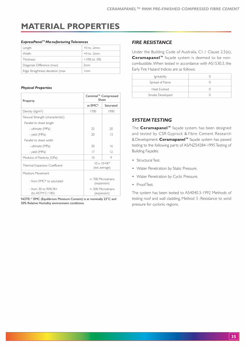
SYSTEM TESTING
The Ceramapanel™ façade system. has been designed and tested by CSR Gyprock & Fibre Cement Research & Development. Ceramapanel™ façade system has passed testing to the following parts of AS/NZS4284-1995 Testing of
The system has been tested to AS4040.3-1992 Methods of testing roof and wall cladding, Method 3 : Resistance to wind pressure for cyclonic regions.
FIRE RESISTANCE
Ceramapanel™ façade system is deemed to be non-combustible. When tested in accordance with AS1530.3, the Early Fire Hazard Indices are as follows:
ExpressPanel™ Ma nufacturing Tolerances
Length +0 to -2mm.
Width +0 to -2mm.
Thickness +10% to -0%.
Diagonals Difference (max) 2mm
Edge Straightness deviation (max 1mm
Physical Properties
PropertyCemintel™ Compressed
Sheet
at EMC* Saturated
Density (kg/m3) 1700 1900
Flexural Strength (characteristic)
Parallel to sheet length
- ultimate (MPa) 25 20
- yield (MPa) 20 13
Parallel to sheet width
- ultimate (MPa) 20 16
- yield (MPa) 17 12
Modulus of Elasticity (GPa) 10 9
Thermal Expansion Coefficient10 x 10-6
(est. average)
Moisture Movement
- from EMC* to saturated� 700 Microstrains
(expansion)
- from 30 to 90% RH (to ASTM C1185)
� 500 Microstrains (expansion)
NOTE: * EMC (Equilibrium Moisture Content) is at nominally 23°C and 50% Relative Humidity environment conditions.
Ignitability 0
Spread of Flame 0
Heat Evolved 0
Smoke Developed 0
MATERIAL PROPERTIES
36
CERAMAPANEL™ 9MM PRE-FINISHED COMPRESSED FIBRE CEMENT
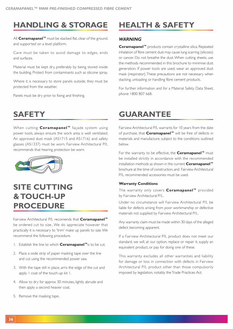
SITE CUTTING
PROCEDURE
Fairview Architectural P/L recomends that Ceramapanel™ be ordered cut to size., We do appreciate however that practically it is necessary to 'trim' make up panels to size. We recommend the following procedure.
1. Establish the line to which Ceramapanel™is to be cut.
2. Place a wide strip of paper masking tape over the line and cut using the recommended power saw.
3. With the tape still in place, arris the edge of the cut and apply 1 coat of the touch-up kit 1.
4. Allow to dry for approx 30 minutes, lightly abrude and then apply a second heavier coat.
5. Remove the masking tape.
All Ceramapanel™ must be stacked flat, clear of the ground, and supported on a level platform.
Care must be taken to avoid damage to edges, ends and surfaces.
Material must be kept dry, preferably by being stored inside the building. Protect from contaminants such as silicone spray.
Where it is necessary to store panels outside, they must be protected from the weather.
Panels must be dry prior to fixing and finishing.
When cutting Ceramapanel™ façade system using power tools, always ensure the work area is well ventilated. An approved dust mask (AS1715 and AS1716) and safety glasses (AS1337) must be worn. Fairview Architectural P/L recommends that hearing protection be worn.
WARNING
Ceramapanel™ products contain crystalline silica. Repeated inhalation of fibre cement dust may cause lung scarring (silicosis) or cancer. Do not breathe the dust. When cutting sheets, use the methods recommended in this brochure to minimise dust generation. If power tools are used, wear an approved dust mask (respirator). These precautions are not necessary when stacking, unloading or handling fibre cement products.
For further information and for a Material Safety Data Sheet, phone 1800 807 668.
GUARANTEE
Fairview Architectural P/L warrants for 10 years from the date of purchase, that Ceramapanel™ will be free of defects in materials and manufacture, subject to the conditions outlined below.
For the warranty to be effective, the Ceramapanel™ must be installed strictly in accordance with the recommended installation methods as shown in the current Ceramapanel™ brochure at the time of construction, and Fairview Architectural P/L. recommended accessories must be used.
The warranty only covers Ceramapanel™ provided by Fairview Architectural P/L.
Under no circumstance will Fairview Architectural P/L be liable for defects arising from poor workmanship or defective materials not supplied by Fairview Architectural P/L.
Any warranty claim must be made within 30 days of the alleged defect becoming apparent.
If a Fairview Architectural P/L product does not meet our standard, we will, at our option, replace or repair it, supply an equivalent product, or pay for doing one of these.
This warranty excludes all other warranties and liability for damage or loss in connection with defects in Fairview Architectural P/L product other than those compulsorily imposed by legislation, notably the Trade Practices Act.
CERAMAPANEL™ 9MM PRE-FINISHED COMPRESSED FIBRE CEMENT
37
NOTES:
Ceramapanel™
ExpressWall WWVertical Gasketkk6-20mm
ExpressWall WWTop HatTT
ExpressExpressWWallall WWWWCSK Screw
Exposed Head Screw
ExpressWall™WW Top TTH 1 1Hat 1.155
Weather Seal WWcompressed in
hole and compressed around screw threadr
ExpressWall WWBacking Strip
Structural supporrr t
E pExpres WsW llall WWWHorizontal Gasketkk
ExpressWall WWVertical Gasketkk
Adhesive
ExpressWall WW TopTTHat
Intermediate Top HatTT
SaSarkiking
Ceramapanelr
Intermediate Top HatTT
Rigid structure at corners
Ceramapanel™
Angle 1mothers
Continuous beaof sof sealaealantnt
Top Hat spacingTT
Top Hat TTspacing
Sarking
10mm nom.
mm gagaallv
nt
Fairview Architectural Pty Ltd18-20 Donald Street Lithgow NSW 2790
Phone: +61 2 6352 2355Fax: +61 2 6352 3115
Email: [email protected]: www.fairviewarchitectural.com.au
We also supply....