CENTURY IIB · 68S75 3 INTRODUCTION The Century Flight Systems, Inc. Century IIB is a light weight...
24
CENTURY IIB AUTOPILOT FLIGHT SYSTEM PILOT’S OPERATING HANDBOOK MARCH 1981 68S75
Transcript of CENTURY IIB · 68S75 3 INTRODUCTION The Century Flight Systems, Inc. Century IIB is a light weight...
CENTURY IIBAUTOPILOT FLIGHT SYSTEM
PILOT’S OPERATING HANDBOOK
MARCH 198168S75
68S75
2
NOTICE
This manual contains generalinformation on the operation of theCentury IIB Autopilot. Specific FAAApproved information on specialtechniques, limitations and emergencyprocedures of a particular model airplaneare contained in either an Airplane FlightManual Supplement or a LimitationsPlacard. Be sure and familiarize yourselfwith the information contained, therein,before flight.
CAUTION
This autopilot system uses the pilot’spanel mounted heading and attitudegyros for sensing. In the event of a gyrofailure or a vacuum (or air) supplysystem failure, autopilot operation mustnot be attempted.
68S75
3
INTRODUCTION
The Century Flight Systems, Inc. Century IIB is a lightweight automatic flight system utilizing an advancedelectronic design for maximum performance and utility.Operating on the versatile 5000 cycle audio frequency,the Century IIB represents a design concept, pioneeredby Century Flight Systems, Inc., in which the conventionalfollow-up or control position feedback signals arereplaced by solid state analytical computers. In additionto providing a more stable and adaptable platform, thenew system can cope with uneven fuel loads anddirectional mistrim without the usual directional errors.
Roll responses are time controlled for human-like controlaction and smooth heading changes.
This manual describes the basic characteristics of eachfunction and its relationship to other functions on theflight system. Maximum utility will be realized afterfamiliarization and practice.
68S75
4
TABLE OF CONTENTS
CAUTION AND NOTICE................................................................... 2
INTRODUCTION............................................................................... 3
TABLE OF CONTENTS ................................................................... 4
DESCRIPTION OF COMMAND FUNCTIONSAUTOPILOT
COMMAND CONSOLE............................................................... 3ROLL ENGAGEMENT ............................................................... 4ROLL COMMAND KNOB............................................................ 4HEADING MODE........................................................................ 5COURSE SELECTOR D.G. ........................................................ 5
LATERAL GUIDANCE SYSTEMCOUPLER MODE SELECTOR................................................... 6OMNI MODE............................................................................... 7NAV MODE................................................................................. 7HEADING MODE........................................................................ 8LOCALIZER - NORMAL MODE.................................................. 8LOCALIZER - REVERSE MODE ................................................ 8
GENERAL OPERATING INSTRUCTIONS
PREFLIGHT INSTRUCTIONS.................................................... 9AUTOPILOT ENGAGE SYSTEM................................................ 10LATERAL GUIDANCE SYSTEM OPERATION........................... 10VOR NAVIGATION..................................................................... 12VOR APPROACH ....................................................................... 14ILS APPROACH- NORMAL ........................................................ 16ILS APPROACH- REVERSE (BACK COURSE) ......................... 18
AIRCRAFT TRIM EFFECTS ............................................................. 20
AIR FILTER INFORMATION............................................................. 21
NOTES.............................................................................................. 22
CENTURY FLIGHT SYSTEMS, INC. AUTOPILOT WARRANTY .... 23
68S75
5
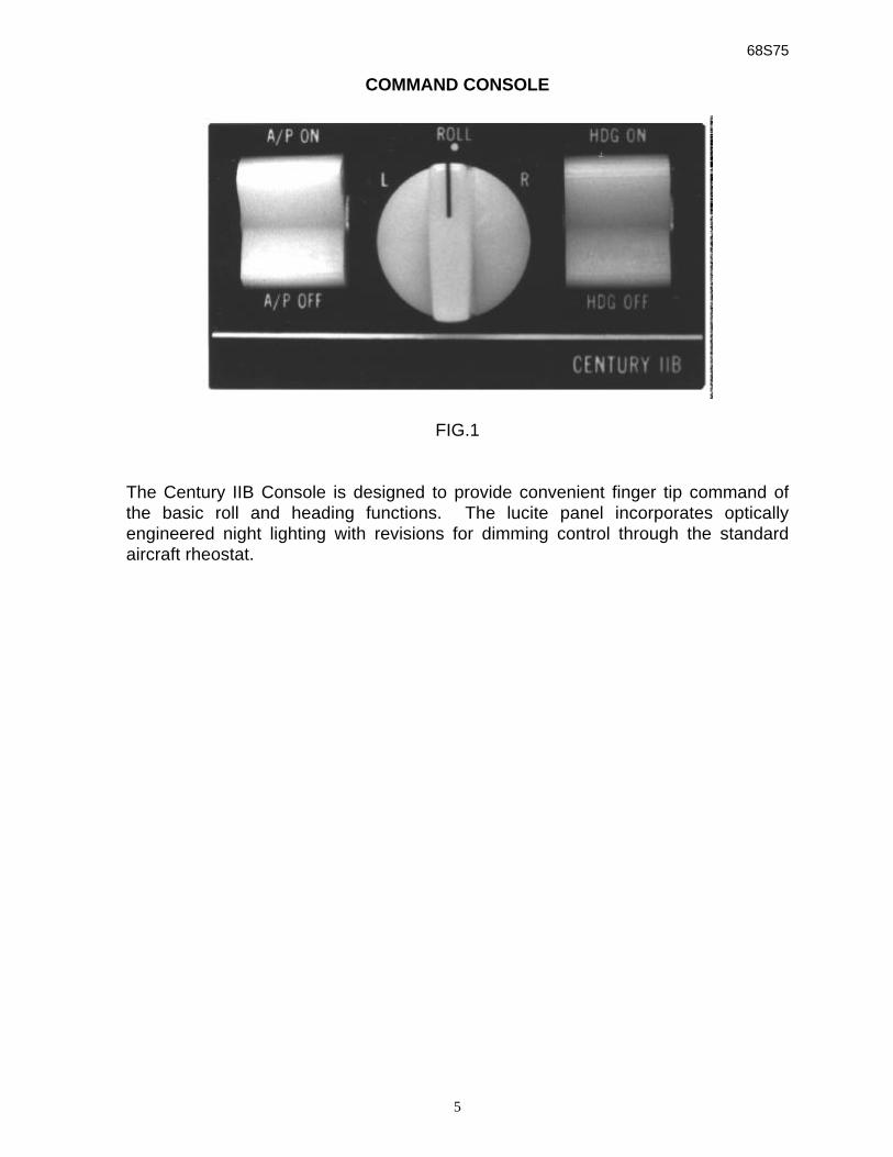
COMMAND CONSOLE
FIG.1
The Century IIB Console is designed to provide convenient finger tip command ofthe basic roll and heading functions. The lucite panel incorporates opticallyengineered night lighting with revisions for dimming control through the standardaircraft rheostat.
68S75
6
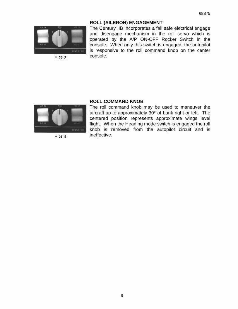
ROLL (AILERON) ENGAGEMENTThe Century IIB incorporates a fail safe electrical engageand disengage mechanism in the roll servo which isoperated by the A/P ON-OFF Rocker Switch in theconsole. When only this switch is engaged, the autopilotis responsive to the roll command knob on the centerconsole.
ROLL COMMAND KNOBThe roll command knob may be used to maneuver theaircraft up to approximately 30° of bank right or left. Thecentered position represents approximate wings levelflight. When the Heading mode switch is engaged the rollknob is removed from the autopilot circuit and isineffective.
FIG.2
FIG.3
68S75
7
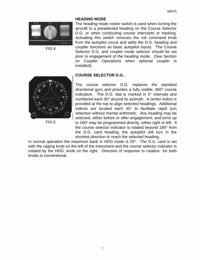
HEADING MODEThe heading mode rocker switch is used when turning theaircraft to a preselected heading on the Course SelectorD.G. or when conducting course intercepts or tracking.Activating this switch removes the roll command knobfrom the autopilot circuit and adds the D.G. heading andcoupler functions as basic autopilot inputs. The CourseSelector D.G. and coupler mode selector should be setprior to engagement of the heading mode. (See Sectionon Coupler Operations when optional coupler isinstalled).
COURSE SELECTOR D.G.
The course selector D.G. replaces the standarddirectional gyro and provides a fully visible, 360° courseindication. The D.G. dial is marked in 5° intervals andnumbered each 30° around its azimuth. A center indice isprovided at the top to align selected headings. Additionalindices are located each 45° to facilitate rapid turnselection without mental arithmetic. Any heading may beselected, either before or after engagement, and turns upto 160° may be programmed directly, either right or left. Ifthe course selector indicator is rotated beyond 180° fromthe D.G. card heading, the autopilot will turn in theshortest direction to reach the selected heading.
In normal operation the maximum bank in HDG mode is 20°. The D.G. card is setwith the caging knob on the left of the instrument and the course selector indicator isrotated by the HDG. knob on the right. Direction of response to rotation for bothknobs is conventional.
FIG.4
FIG.5
68S75
8
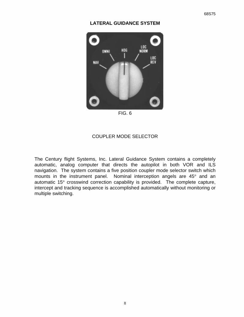
LATERAL GUIDANCE SYSTEM
FIG. 6
COUPLER MODE SELECTOR
The Century flight Systems, Inc. Lateral Guidance System contains a completelyautomatic, analog computer that directs the autopilot in both VOR and ILSnavigation. The system contains a five position coupler mode selector switch whichmounts in the instrument panel. Nominal interception angels are 45° and anautomatic 15° crosswind correction capability is provided. The complete capture,intercept and tracking sequence is accomplished automatically without monitoring ormultiple switching.
68S75
9
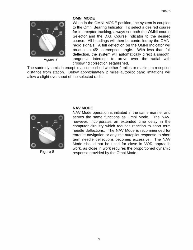
OMNI MODEWhen in the OMNI MODE position, the system is coupledto the Omni Bearing Indicator. To select a desired coursefor interceptor tracking, always set both the OMNI courseSelector and the D.G. Course Indicator to the desiredcourse. All headings will then be controlled by the OMNIradio signals. A full deflection on the OMNI Indicator willproduce a 45° interception angle. With less than fulldeflection, the system will automatically direct a smooth,tangential intercept to arrive over the radial withcrosswind correction established.
The same dynamic intercept is accomplished whether 2 miles or maximum receptiondistance from station. Below approximately 2 miles autopilot bank limitations willallow a slight overshoot of the selected radial.
NAV MODENAV Mode operation is initiated in the same manner andserves the same functions as Omni Mode. The NAV,however, incorporates an extended time delay in thecomputer circuitry which reduces reaction to short termneedle deflections. The NAV Mode is recommended forenroute navigation or anytime autopilot response to shortterm needle deflections becomes excessive. The NAVMode should not be used for close in VOR approachwork, as close in work requires the proportioned dynamicresponse provided by the Omni Mode.
Figure 7
Figure 8
68S75
10
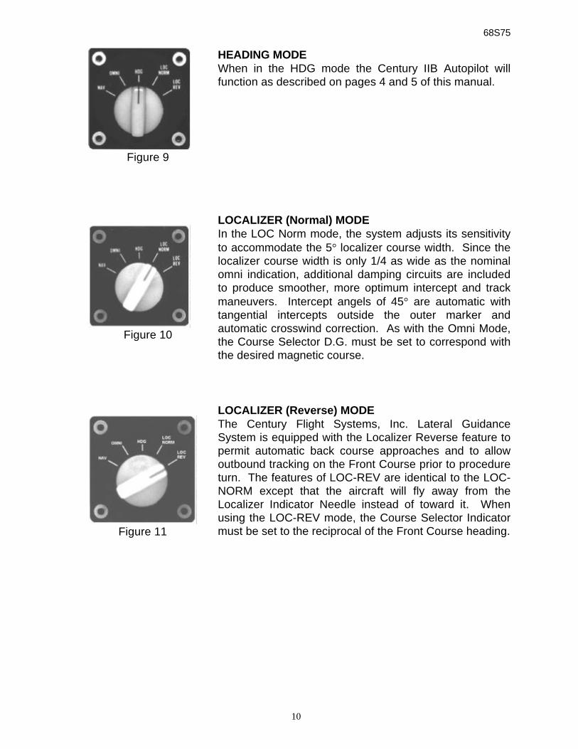
HEADING MODEWhen in the HDG mode the Century IIB Autopilot willfunction as described on pages 4 and 5 of this manual.
LOCALIZER (Normal) MODEIn the LOC Norm mode, the system adjusts its sensitivityto accommodate the 5° localizer course width. Since thelocalizer course width is only 1/4 as wide as the nominalomni indication, additional damping circuits are includedto produce smoother, more optimum intercept and trackmaneuvers. Intercept angels of 45° are automatic withtangential intercepts outside the outer marker andautomatic crosswind correction. As with the Omni Mode,the Course Selector D.G. must be set to correspond withthe desired magnetic course.
LOCALIZER (Reverse) MODEThe Century Flight Systems, Inc. Lateral GuidanceSystem is equipped with the Localizer Reverse feature topermit automatic back course approaches and to allowoutbound tracking on the Front Course prior to procedureturn. The features of LOC-REV are identical to the LOC-NORM except that the aircraft will fly away from theLocalizer Indicator Needle instead of toward it. Whenusing the LOC-REV mode, the Course Selector Indicatormust be set to the reciprocal of the Front Course heading.
Figure 9
Figure 10
Figure 11
68S75
11
GENERAL OPERATIONS
The Century IIB and optional coupler are FAA approved on each make and modelaircraft under a “Supplemental Type Certificate” STC
There are no restrictions to operations in turbulence and as a general rule autopilotoperation in turbulence will result in smoother operation.
Autopilot operating limitations and any special limitations will be specified on theLimitations Placard or in the Airplane Flight Manual Supplement. This should becarefully read and understood.
Autopilot override forces are adjusted to the servo power output requirements ofeach particular aircraft. The autopilot may be overridden by the pilot withoutdamage to the system.
NOTE: Only Century Flight Systems, Inc. trained specialists at approved servicecenters should adjust servo torque outputs.
PILOT’S PREFLIGHT PROCEDURE1. With engines running and gyros erected, check vacuum readings. Should be
4.75” to 5.00” HG.2. With the autopilot off, place coupler mode selector on HDG. position. Center
roll knob and D.G. course selector indicator.3. Engage roll switch, rotate roll command knob left and right and note that the
control wheel responds in the proper direction.4. Engage the heading mode switch and rotate course selector indicator to
either side. Note roll servo response; again, without aerodynamic response,servo action is unlimited.
5. Override the autopilot at the control wheel in both directions. Force requiredshould be approximately 15 lbs. At wheel edge dependent upon aircraftmodel.
6. Disengage autopilot before takeoff.
AUTOPILOT ENGAGE SEQUENCE (IN FLIGHT)1. Trim aircraft to a wings level flight attitude.2. Center roll knob and engage autopilot “ON” switch.3. If navigation mode selector is installed select “HDG” mode.4. Center D.G. course selector indicator and engage heading mode switch.
LATERAL GUIDANCE SYSTEM OPERATIONPerform Steps 1-4 above then continue below:
5. Match course selector indicator to selected VOR or ILS course.6. Select Lateral Guidance Mode desired.
68S75
12
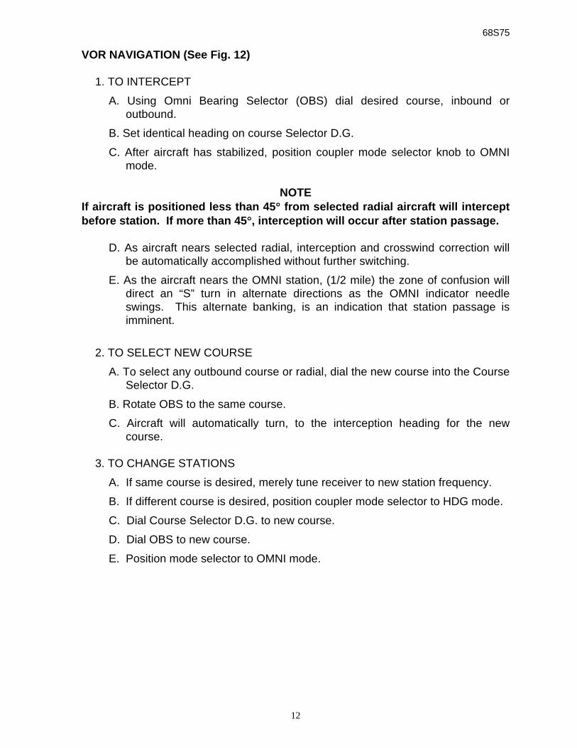
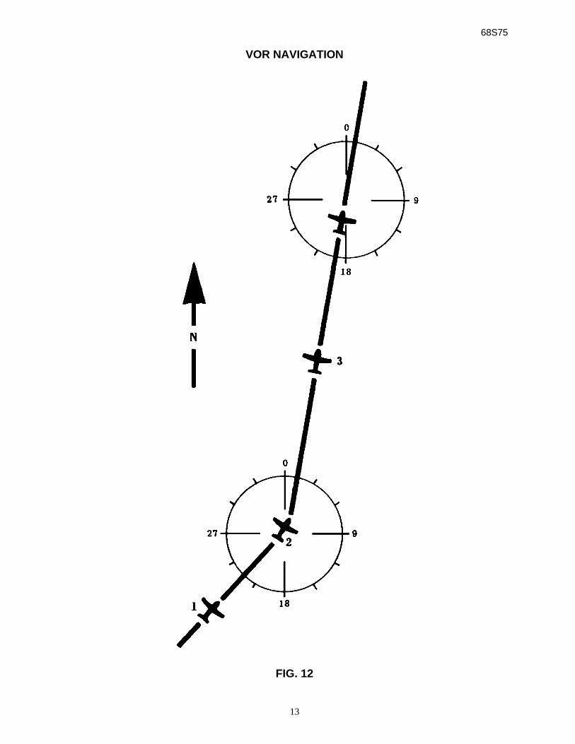
VOR NAVIGATION (See Fig. 12)
1. TO INTERCEPT
A. Using Omni Bearing Selector (OBS) dial desired course, inbound oroutbound.
B. Set identical heading on course Selector D.G.
C. After aircraft has stabilized, position coupler mode selector knob to OMNImode.
NOTEIf aircraft is positioned less than 45°° from selected radial aircraft will interceptbefore station. If more than 45°°, interception will occur after station passage.
D. As aircraft nears selected radial, interception and crosswind correction willbe automatically accomplished without further switching.
E. As the aircraft nears the OMNI station, (1/2 mile) the zone of confusion willdirect an “S” turn in alternate directions as the OMNI indicator needleswings. This alternate banking, is an indication that station passage isimminent.
2. TO SELECT NEW COURSE
A. To select any outbound course or radial, dial the new course into the CourseSelector D.G.
B. Rotate OBS to the same course.
C. Aircraft will automatically turn, to the interception heading for the newcourse.
3. TO CHANGE STATIONS
A. If same course is desired, merely tune receiver to new station frequency.
B. If different course is desired, position coupler mode selector to HDG mode.
C. Dial Course Selector D.G. to new course.
D. Dial OBS to new course.
E. Position mode selector to OMNI mode.
68S75
13
VOR NAVIGATION
FIG. 12
68S75
14
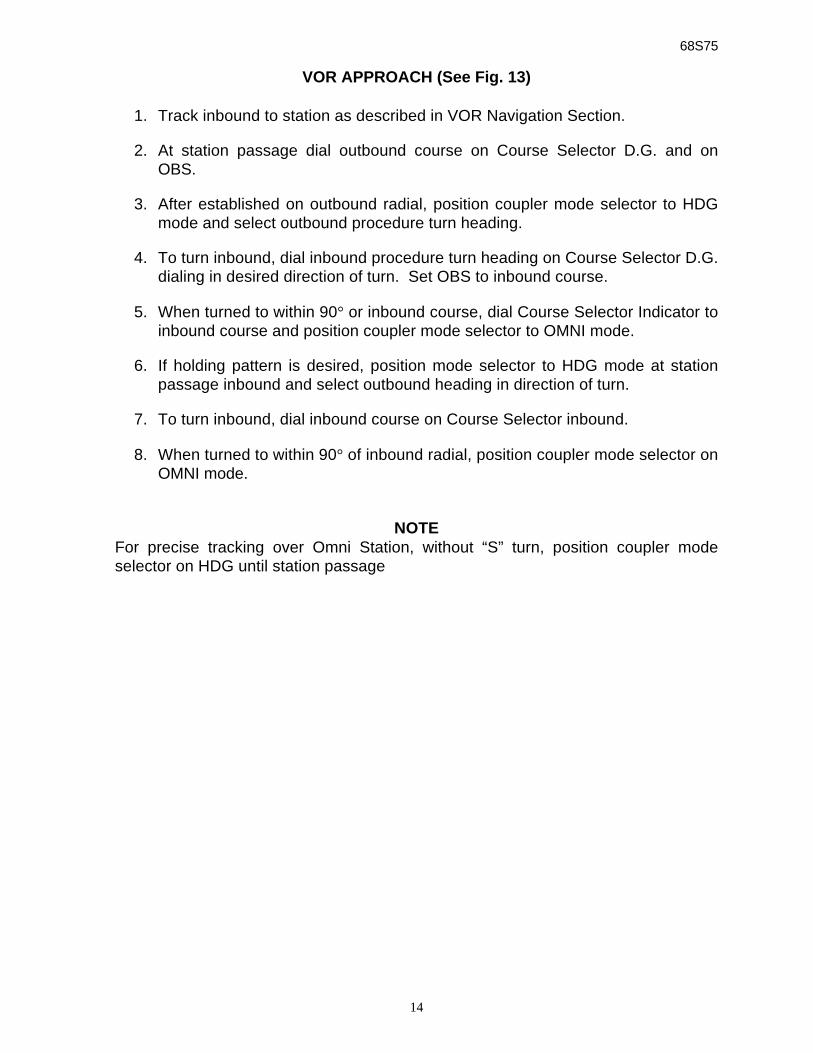
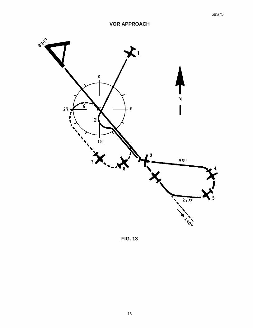
VOR APPROACH (See Fig. 13)
1. Track inbound to station as described in VOR Navigation Section.
2. At station passage dial outbound course on Course Selector D.G. and onOBS.
3. After established on outbound radial, position coupler mode selector to HDGmode and select outbound procedure turn heading.
4. To turn inbound, dial inbound procedure turn heading on Course Selector D.G.dialing in desired direction of turn. Set OBS to inbound course.
5. When turned to within 90° or inbound course, dial Course Selector Indicator toinbound course and position coupler mode selector to OMNI mode.
6. If holding pattern is desired, position mode selector to HDG mode at stationpassage inbound and select outbound heading in direction of turn.
7. To turn inbound, dial inbound course on Course Selector inbound.
8. When turned to within 90° of inbound radial, position coupler mode selector onOMNI mode.
NOTEFor precise tracking over Omni Station, without “S” turn, position coupler modeselector on HDG until station passage
68S75
15
VOR APPROACH
FIG. 13
68S75
16
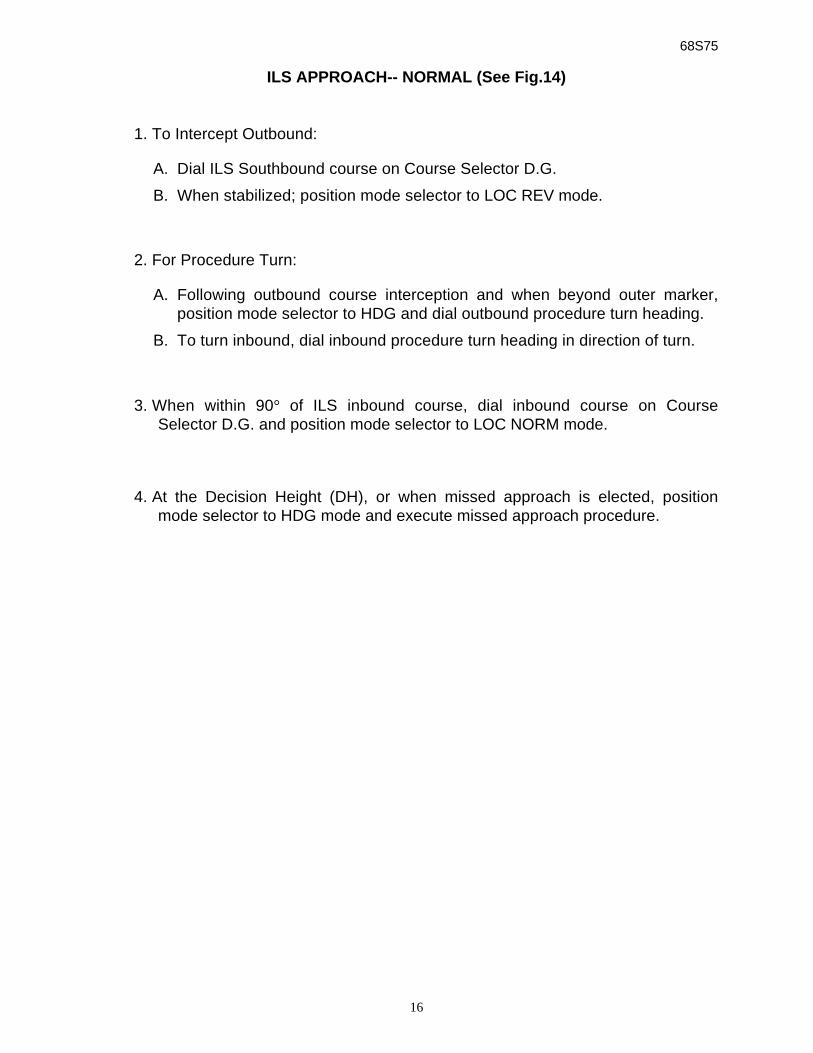
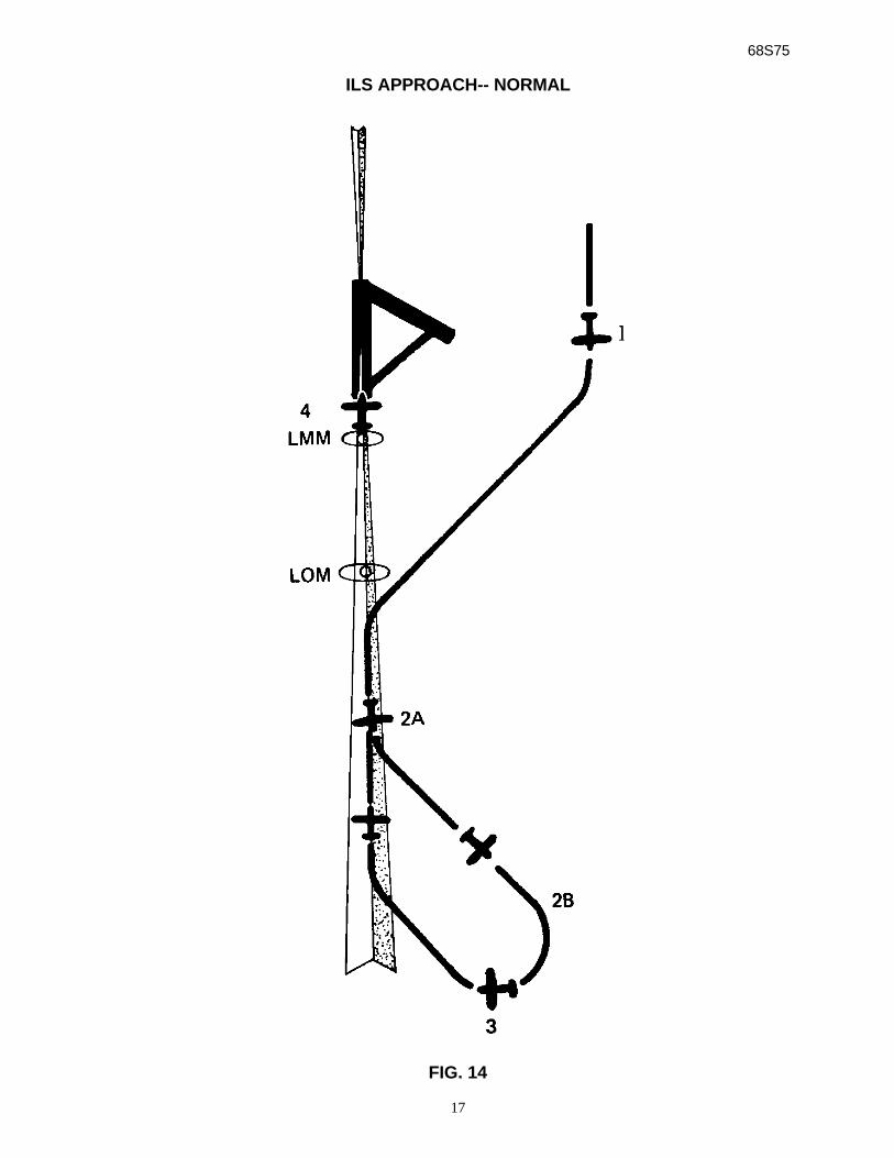
ILS APPROACH-- NORMAL (See Fig.14)
1. To Intercept Outbound:
A. Dial ILS Southbound course on Course Selector D.G.
B. When stabilized; position mode selector to LOC REV mode.
2. For Procedure Turn:
A. Following outbound course interception and when beyond outer marker,position mode selector to HDG and dial outbound procedure turn heading.
B. To turn inbound, dial inbound procedure turn heading in direction of turn.
3. When within 90° of ILS inbound course, dial inbound course on CourseSelector D.G. and position mode selector to LOC NORM mode.
4. At the Decision Height (DH), or when missed approach is elected, positionmode selector to HDG mode and execute missed approach procedure.
68S75
17
ILS APPROACH-- NORMAL
FIG. 14
68S75
18
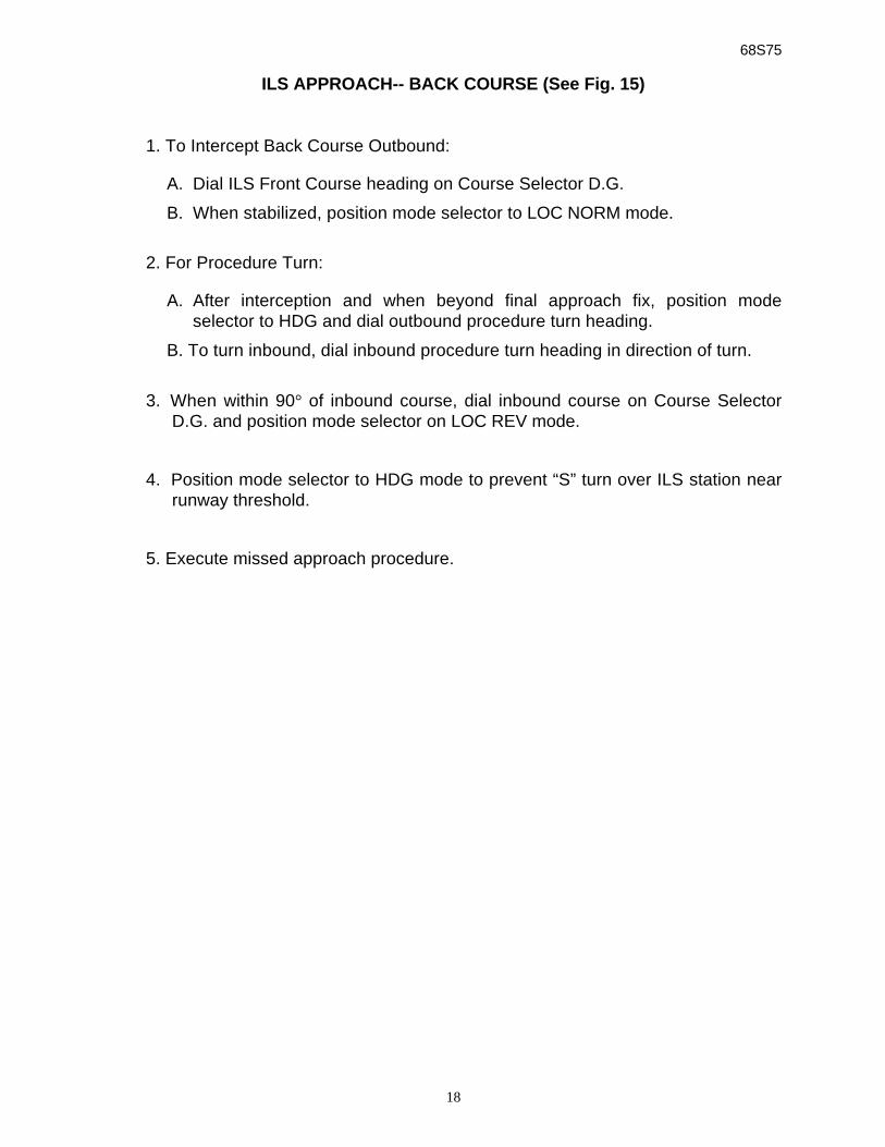
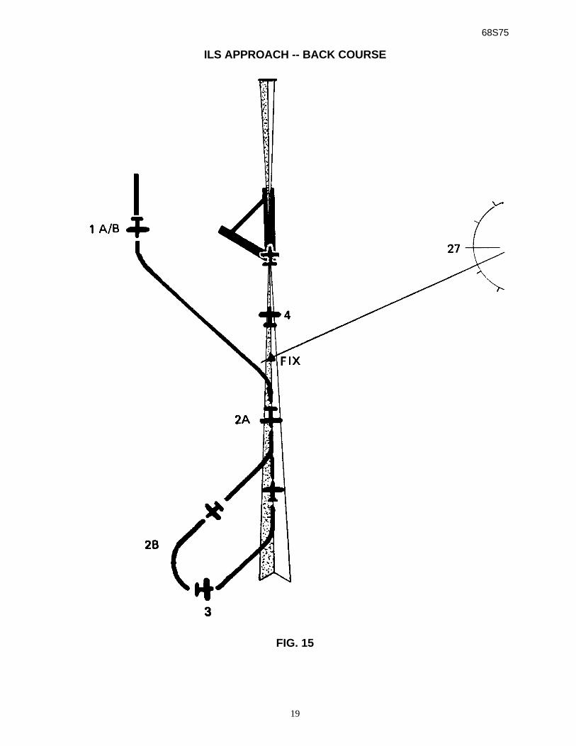
ILS APPROACH-- BACK COURSE (See Fig. 15)
1. To Intercept Back Course Outbound:
A. Dial ILS Front Course heading on Course Selector D.G.
B. When stabilized, position mode selector to LOC NORM mode.
2. For Procedure Turn:
A. After interception and when beyond final approach fix, position modeselector to HDG and dial outbound procedure turn heading.
B. To turn inbound, dial inbound procedure turn heading in direction of turn.
3. When within 90° of inbound course, dial inbound course on Course SelectorD.G. and position mode selector on LOC REV mode.
4. Position mode selector to HDG mode to prevent “S” turn over ILS station nearrunway threshold.
5. Execute missed approach procedure.
68S75
19
ILS APPROACH -- BACK COURSE
FIG. 15
68S75
20
CAUTIONWhen electrical power is first applied to the NSD-360A instrument,the compass card may rotate or “slew” rapidly. This is NOT anindication that the compass system is orienting itself to the propermagnetic heading. The proper heading orientation must beverified and set prior to takeoff and should be verified prior toapproach to landing using the magnetic compass.
CAUTIONThe NSD has an optional slaving feature that requires initialheading setting on start-up. Subsequent resetting of the headingcard, required manually on non-slaved versions, is automaticallyaccomplished with the slaved version.
\Proper heading synchronization must be verified on both non-slaved and slaved NSD-360A units. This is accomplished bycomparing the heading displayed under the lubber line with themagnetic compass...
The NSD-360A incorporates a heading warning flag to warn of lossof either air or electronic power. Appearance of the flag duringflight should be sufficient grounds to question the validity of thedisplayed heading. In slaved versions, the slaving meter shouldoscillate about a 45°° point to show that the slaving circuits areaccomplishing their function. Should the needle remainmotionless or either vertical or horizontal for an extended period(two minutes) in level flight, the heading should be manually setusing the magnetic compass and the performance of the headingcard observed. If this condition persists, set the slaving modeswitch to SL#2 on free gyro. In free gyro mode, the instrumentmust be periodically reset to manually counteract the effects ofgyro precession.
68S75
21
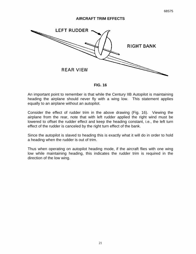
AIRCRAFT TRIM EFFECTS
FIG. 16
An important point to remember is that while the Century IIB Autopilot is maintainingheading the airplane should never fly with a wing low. This statement appliesequally to an airplane without an autopilot.
Consider the effect of rudder trim in the above drawing (Fig. 16). Viewing theairplane from the rear, note that with left rudder applied the right wind must belowered to offset the rudder effect and keep the heading constant, i.e., the left turneffect of the rudder is canceled by the right turn effect of the bank.
Since the autopilot is slaved to heading this is exactly what it will do in order to holda heading when the rudder is out of trim.
Thus when operating on autopilot heading mode, if the aircraft flies with one winglow while maintaining heading, this indicates the rudder trim is required in thedirection of the low wing.
68S75
22
AIR FILTER
AIR FILTER AND ELEMENT
The Century flight Systems, Inc. 1X314 central air filter is incorporated on all 3” gyrosystems with the exception of aircraft with original equipment filters of like quality.
The 1X314 filter system uses the 51A5 replaceable filter element which is capable ofremoving 97% of all contaminating substances above 3 microns. This includestobacco tars that would otherwise be harmful to bearings and vanes. Because ofthis exceptional filtering ability contaminants tend to accumulate at higher rate thanin other types. It is therefore considered necessary that filter elements be replacedat each 100 hour period and that filters subjected to tobacco tars, industrial smokeand like environment, be inspected each 50 hours for possible replacement.
Gyro warranty is dependent upon following this procedure.

68S75
23
NOTES
68S75
24
Effective: July 4, 1975
LIMITED WARRANTY CENTURY FLIGHT SYSTEMS, INC. AUTOPILOTEach new Century Flight Systems, Inc. Autopilot is warranted by themanufacturer to be free from defects in material and workmanship undernormal use, subject to the following conditions:
1. Century Flight Systems, Inc. Will through its designated service facilitiesat its option either repair or replace new components which, shall within(12 months after date of installation, be found, to Century Flight Systems,Inc. Satisfaction, to have been defective in material or workmanshipunder normal use.
2. The warranty registration must be signed and returned to Century FlightSystems, Inc. within ten days of equipment installation date. In the eventthat the registration card is not returned within this time, the date ofshipment from the factory will be deemed to be the installation date.
3. This warranty will not apply to any product which has been installed,repaired, or altered in any way whatsoever in Century Flight Systems,Inc. Opinion to adversely affect its performance or reliability, or whichhas been subject to mis-use, contamination, negligence, or accident.
4. Cost of transportation, removal or reinstallation are at the option ofCentury Flight Systems, Inc.
5. This is Century Flight Systems, Inc. sole express warranty with respect tothe goods supplied herein. CENTURY FLIGHT SYSTEMS, INC. MAKESNO OTHER EXPRESS WARRANTY OF ANY KIND WHATSOEVER.CENTURY FLIGHT SYSTEMS, INC. EMPLOYEES MAY HAVE MADEORAL STATEMENTS ABOUT THE PRODUCTS DESCRIBED IN THISCONTRACT. SUCH STATEMENTS DO NOT CONSTITUTEWARRANTIES, SHALL NOT BE RELIED UPON BY THE CUSTOMER,AND ARE NOT PART OF THE SALE CONTRACT.
6. THE DURATION OF ANY IMPLIED WARRANTY, AND OF ALLWARRANTIES OF MERCHANTABILITY AND FITNESS FOR APARTICULAR PURPOSE, SHALL BE LIMITED TO (12) MONTHSCOMMENCING AT DATE OF INSTALLATION TO THE FULL EXTENTPERMITTED BY APPLICABLE LAW, CONSEQUENTIAL DAMAGE OFBREECH OF ANY WARRANTY ARE HEREBY DISCLAIMED ANDEXCLUDED BY CENTURY FLIGHT SYSTEMS, INC.
Century Flight Systems, Inc.P.O. Box 610
Municipal AirportMineral Wells. Texas
76067August 1983